JP5777330B2 - Turbine blade - Google Patents
Turbine blade Download PDFInfo
- Publication number
- JP5777330B2 JP5777330B2 JP2010268897A JP2010268897A JP5777330B2 JP 5777330 B2 JP5777330 B2 JP 5777330B2 JP 2010268897 A JP2010268897 A JP 2010268897A JP 2010268897 A JP2010268897 A JP 2010268897A JP 5777330 B2 JP5777330 B2 JP 5777330B2
- Authority
- JP
- Japan
- Prior art keywords
- blade
- airfoil
- airfoil portion
- platform
- shroud
- Prior art date
- Legal status (The legal status is an assumption and is not a legal conclusion. Google has not performed a legal analysis and makes no representation as to the accuracy of the status listed.)
- Expired - Fee Related
Links
Images


Classifications
-
- F—MECHANICAL ENGINEERING; LIGHTING; HEATING; WEAPONS; BLASTING
- F01—MACHINES OR ENGINES IN GENERAL; ENGINE PLANTS IN GENERAL; STEAM ENGINES
- F01D—NON-POSITIVE DISPLACEMENT MACHINES OR ENGINES, e.g. STEAM TURBINES
- F01D5/00—Blades; Blade-carrying members; Heating, heat-insulating, cooling or antivibration means on the blades or the members
- F01D5/12—Blades
- F01D5/14—Form or construction
- F01D5/141—Shape, i.e. outer, aerodynamic form
- F01D5/146—Shape, i.e. outer, aerodynamic form of blades with tandem configuration, split blades or slotted blades
-
- F—MECHANICAL ENGINEERING; LIGHTING; HEATING; WEAPONS; BLASTING
- F01—MACHINES OR ENGINES IN GENERAL; ENGINE PLANTS IN GENERAL; STEAM ENGINES
- F01D—NON-POSITIVE DISPLACEMENT MACHINES OR ENGINES, e.g. STEAM TURBINES
- F01D5/00—Blades; Blade-carrying members; Heating, heat-insulating, cooling or antivibration means on the blades or the members
- F01D5/12—Blades
- F01D5/14—Form or construction
- F01D5/147—Construction, i.e. structural features, e.g. of weight-saving hollow blades
-
- F—MECHANICAL ENGINEERING; LIGHTING; HEATING; WEAPONS; BLASTING
- F01—MACHINES OR ENGINES IN GENERAL; ENGINE PLANTS IN GENERAL; STEAM ENGINES
- F01D—NON-POSITIVE DISPLACEMENT MACHINES OR ENGINES, e.g. STEAM TURBINES
- F01D5/00—Blades; Blade-carrying members; Heating, heat-insulating, cooling or antivibration means on the blades or the members
- F01D5/12—Blades
- F01D5/14—Form or construction
- F01D5/18—Hollow blades, i.e. blades with cooling or heating channels or cavities; Heating, heat-insulating or cooling means on blades
- F01D5/187—Convection cooling
- F01D5/188—Convection cooling with an insert in the blade cavity to guide the cooling fluid, e.g. forming a separation wall
- F01D5/189—Convection cooling with an insert in the blade cavity to guide the cooling fluid, e.g. forming a separation wall the insert having a tubular cross-section, e.g. airfoil shape
Description
本発明は、タービンブレードに関する。 The present invention relates to a turbine blade.
特に本発明のタービンブレードは、ガスタービンあるいは蒸気タービンのロータブレードおよび/またはガイドベーン(すなわちステータブレード)であってもよい。 In particular, the turbine blades of the present invention may be rotor blades and / or guide vanes (ie, stator blades) of gas turbines or steam turbines.
単純さと簡潔さを得るために、以下タービンに関しては、ガスタービンのロータブレードとする。 For simplicity and brevity, the following turbine is referred to as a gas turbine rotor blade.
ガスタービンのタービンロータブレードは、ブレード担持体の対応する座部に接続すべき蟻継部/モミの木形状部を備えた根元部を有するプラットフォームを備えていることで知られている。 Turbine rotor blades of gas turbines are known for having a platform with a root with a dovetail / fir tree shape to be connected to a corresponding seat of the blade carrier.
プラットフォームの中央部分から翼形は延びており、圧力側と吸引側により成形されており、これらの圧力側と吸引側はタービンを通過する高温ガスと協働するように配置されている。 An airfoil extends from the central portion of the platform and is shaped by a pressure side and a suction side, which are arranged to cooperate with hot gas passing through the turbine.
ブレード担持体上で組立てられると、タービンロータブレードは、そのプラットフォームが環状高温ガス通路の内側の境界を定めるように次々と隣接してすべて配置されている。 When assembled on a blade carrier, the turbine rotor blades are all arranged one after the other so that their platforms delimit the inner side of the annular hot gas path.
それにもかかわらず、これらのブレードは短所を多く有しており、以下に詳しく列挙する。 Nevertheless, these blades have many disadvantages and are listed in detail below.
作動時に多量のパージ空気を二つの隣接したプラットフォーム間の間隙を通る高温ガス通路内に導入する必要があり、それ以上のパージ空気をタービンロータブレードを取り囲んでいるケーシングから導入する必要がある。高温ガス通路内に導入されるこのパージ空気によってガスタービンの効率は低下する。 In operation, a large amount of purge air must be introduced into the hot gas path through the gap between two adjacent platforms, and more purge air must be introduced from the casing surrounding the turbine rotor blades. This purge air introduced into the hot gas passage reduces the efficiency of the gas turbine.
さらに、翼形先端部とケーシングの間の間隙により漏洩量が通過し、さらにこの漏洩量によりガスタービンの効率が低下する。 Further, the amount of leakage passes through the gap between the airfoil tip and the casing, and the amount of leakage further reduces the efficiency of the gas turbine.
ブレードは作動時に冷却空気が駆動される多数の内部冷却流路を備えているのが普通である。 The blade typically has a number of internal cooling channels through which cooling air is driven during operation.
この理由で、ブレードは冷却流路を形成している内部セラミックコアで鋳造することにより鋳造されるのが普通である。この鋳造技術は極めて高価であり、かつ時間を費やす。加えて、(セラミックコア内に形成された)流路は冷却点の見地から見て理想的な特徴を全て備えていないが、製造工程を単純かつ安価にするために最適化されている。 For this reason, blades are usually cast by casting with an internal ceramic core that forms a cooling channel. This casting technique is extremely expensive and time consuming. In addition, the flow path (formed in the ceramic core) does not have all the ideal features from the point of view of the cooling point, but is optimized to make the manufacturing process simple and inexpensive.
製造の制約のために、冷却流路は効率的な冷却を提供できず、作動時に過熱と困難な冷却が問題となることがある。 Due to manufacturing constraints, the cooling channel cannot provide efficient cooling, and overheating and difficult cooling can be problematic during operation.
従って本発明の技術的課題は、従来技術の前記問題がなくなるブレードを提供することにある。 Therefore, the technical problem of the present invention is to provide a blade that eliminates the problems of the prior art.
この技術的課題の範囲内において、本発明の態様は、高温ガス通路内に導入されるパージ空気が従来のブレードに関して必要とされる空気と比べて低減されるブレードを提供することであり、従って効率が増大する。 Within the scope of this technical problem, an aspect of the present invention is to provide a blade in which the purge air introduced into the hot gas passage is reduced compared to the air required for a conventional blade, and therefore Efficiency increases.
さらに、本発明の特に有利な実施例において、効率がさらに増すように、各翼形の先端部とそれを取囲んでいるケーシングの間の漏洩も減少する。 In addition, in a particularly advantageous embodiment of the invention, leakage between each airfoil tip and the surrounding casing is also reduced so that efficiency is further increased.
本発明の他の態様は、(例えば内側冷却流路あるいはフィンのような)各翼形の熱伝達促進体が相応する従来のブレードに必要とされる費用に比べて低い費用で、かつ時間的に効率的な方法で簡単に製造されるブレードを提供することである。 Another aspect of the present invention is that each airfoil heat transfer facilitator (such as an inner cooling channel or fin) is less expensive and more time-consuming than the cost required for a corresponding conventional blade. It is to provide a blade that is easily manufactured in an efficient manner.
本発明の他の態様は、最適化された熱伝達促進体、すなわち製造の制約の代わりに所望の冷却効果によりその構造と形状が主に境界を定められる熱伝達促進体を製造することである。 Another aspect of the present invention is to produce an optimized heat transfer enhancer, i.e., a heat transfer enhancer whose structure and shape are primarily bounded by the desired cooling effect instead of manufacturing constraints. .
これらのおよび別の態様を一緒に備えた技術的課題は、添付の請求項に従ったブレードを提供することにより本発明により達成される。 The technical problem together with these and other aspects is achieved according to the invention by providing a blade according to the appended claims.
本発明の特に有利な実施例において、翼形の振動問題は減少する。 In a particularly advantageous embodiment of the invention, airfoil vibration problems are reduced.
本発明の他の特徴と長所は、添付の図における制限していない実例により図示した、好ましいが独占的ではない本発明によるブレードの実施例の説明から明らかである。 Other features and advantages of the present invention are apparent from the description of the preferred but not exclusive embodiments of the blade according to the present invention, illustrated by the non-limiting examples in the accompanying drawings.
以下に、ガスタービンのロータブレードに関して記載する。本発明の様々な実施例において、ブレードはガスタービンのガイドベーンであってもよく、あるいはさらに別の実施例においては、蒸気タービンもしくは異なる回転機械のロータブレードあるいはステータブレードであってもよい。 Hereinafter, the rotor blade of the gas turbine will be described. In various embodiments of the present invention, the blades may be gas turbine guide vanes, or in yet other embodiments may be steam turbines or rotor blades or stator blades of different rotating machines.
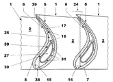
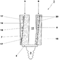
図1に関して、タービンブレード1はプラットフォーム2を具備し、このプラットフォームは、(図1には示していないが図5では22で表示した)ブレード担持体に接続されるように配置された根元部3を備えている。
With reference to FIG. 1, the
タービンブレード1のプラットフォーム2の反対側からは、翼形部分5,6が延びている。
翼形部分は各々、一つの作動面7,8を規定しており、この作動面は他の翼形部分に面している面である。
Each airfoil portion defines one
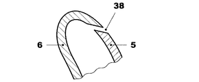
この点において、図2および3に関して、同じタービンブレード1の他の翼形部分5に面している翼形部分6の面8は、タービンブレード1の作動面である。すなわちタービンブレードがガスタービン内に組立てられた際に、かつ同じガスタービンが作動中に、高温ガス通路内に流れ込んでいる高温ガスと接触するように配置されている面である。
In this respect, with reference to FIGS. 2 and 3, the
同じように、図2には翼形部分5の作動面7が示してあり、この作動面は同じタービンブレード1の他の翼形部分に面しており、かつ作動時に高温ガスと接触するように配置されている翼形部分5の面である。
Similarly, FIG. 2 shows the
多数のタービンブレード1が互いに接続していると、特に翼形部分5の作動面7は吸引側の境界を定め、翼形部分6の作動面8は境界を定められるべきエアフォイルの圧力側の境界を定める。
When a number of
タービンブレード1はさらに各翼形部分5および6の端部に接続されたシュラウド10を備えており、従って翼形部分5および6とシュラウド10を備えたプラットフォーム2は閉鎖した流路11の境界を定める。
The
作動面7,8に向かい合った、翼形部分5,6の面14,15は、翼形部分の内側面の境界を定めており、これらの内側面は、多数のタービンブレード1がブレード担持体上に組立てられている場合、隣接した二つの翼形部分により境界を定められている。すなわち、これらの内側面14,15は、ガスタービンが正常に作動している間は高温ガスと接触しない。
Faces 14 and 15 of the
製造時にこれらの内側面14および15は、作業者と製造工具にとって直接手が届き作業し易く、従来の工具を使用してかつ限られたコストで、これらの内側面はきわめて単純でかつ速い方法で必要に応じて成形することができる。言い換えると、極めて複雑な伝熱促進体17を備えたこれら内側面を成形することは従来のタービンブレードに比べると簡単でかつ安価である。
During manufacturing, these
例えば伝熱促進体17は、内側面14および/または15から延びている、熱交換を増大させるように配置されたリブ、ピンあるいはフィンである。
For example, the
さらに、翼形部分5および/または6の内側面14,15は、多数のブレード1が次々とブレード担持体上に組立てられた場合、スペーサ18が二つの隣接した翼形部分5,6の間に挿入されているように、スペーサ18を備えていると好ましい。
Furthermore, the
図10はスペーサ18の好ましい実施例を示している。この実施例ではブレード部分5および6は共にスペーサ18を有しており、これらのスペーサは互いにスライドするように接続している。
FIG. 10 shows a preferred embodiment of the
翼形部分5,6の少なくとも一つは、それを通して冷却空気を通過させるように配置された貫通孔20を備えている。
At least one of the
図1および4はこれらの貫通孔を備えた翼形部分6だけを示しており、異なる実施例において翼形部分5,6は両者共、これらの貫通孔20を備えているか、あるいは翼形部分5だけが貫通孔20を備えていてもよいことがいずれにせよ明らかである。
1 and 4 show only the
さらに、別の実施例においてさえ、貫通孔20はプラットフォーム2および/またはシュラウド10に設けられていてもよい。
Further, even in other embodiments, the through
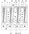
図3および5はブレード担持体22上に組立てられた、他のブレード1に接続したブレード1を示している。
3 and 5 show a
これらの図に示した通り、ブレード1の圧力側の境界を定めている作動面8を備えた翼形部分6は、異なる隣接したブレード1の吸引側の境界を定めている作動面7を備えた翼形部分5に接続している。すなわち、互いに接続した二つの異なる隣接したブレード1の二つの翼形部分5,6は翼形24の境界を定めている。
As shown in these figures, the
図3から、接続した翼形部分5,6の間(すなわち、これら翼形部分により境界を定められた各翼形24の内側)には空間25が境界を定められていることがわかる。
It can be seen from FIG. 3 that a
空間25の下側部分は二つの隣接したブレード1のプラットフォーム2により閉鎖されており、空間の上側部分は二つの隣接したブレード1のシュラウド10により閉鎖されている。
The lower part of the
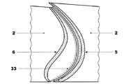
プラットフォーム2はハウジングの封隙を容易にするために真直ぐな側方縁部を有しているのが好ましい(図2)。
異なる実施例(図11)において、プラットフォーム2は湾曲した輪郭で成形された側方縁部を備えている。
In a different embodiment (FIG. 11), the
同様にして、シュラウド10はハウジングの封隙を容易にするために真直ぐな側方縁部を有している。
Similarly, the
異なる実施例においてはシュラウド10も湾曲した輪郭で成形された側方縁部を備えている。
In a different embodiment, the
プラットフォームとシュラウドの側方縁部が、上記引用されたタイプのいずれの組合せを備えていてもよいのはいずれにせよ明らかである(例えば真直ぐな側方縁部を備えたプラットフォームと湾曲した輪郭を備えたシュラウド、もしくはその逆の組合せも同様である)。 Obviously, the platform and shroud side edges may comprise any combination of the above-cited types (eg, platforms with straight side edges and curved contours). The shroud provided or vice versa is also the same).
空間25は空であっても、あるいは伝熱促進体(例えばリブおよび/またはピンおよび/またはフィン17)および/またはスペーサ18を収容していてもよい。
The
さらに、空間25は区間25の内側の圧縮された冷却空気を供給するために配置された管状インサート27を収容してもよい。
Furthermore, the
特に管状インサート27はプラットフォーム2の貫通孔26を通過し、かつブレードの根元部3の領域28において、空間25の内側に一方の端部を有しており、空間25の外側に反対側の端部を有している。
In particular, the
管状インサート27は例えば円形あるいは楕円形のような異なる形状を有していてもよいが、それでも内側面14および15の内側輪郭に似た形状を有しているのが好ましい。
The
さらに、管状インサート27は翼形部分5および6から隔てられており、かつ翼形部分5および6の内側面14および15に対して静止しているように配置されたスペーサ30を備えていてもよい。
Furthermore, the
他の実施例において、管状インサート27はスペーサ30を備えていなくてもよく、スペーサ30は翼形部分5および6の内側面14および15から延びていてもよい。この実施例において、スペーサ30はスペーサ18のための図10に示したのと同じ構造を有していてもよい。
In other embodiments, the
管状インサート27は冷却空気を通過させるように配置された、多数の貫通孔31を有しており、冷却空気がそこを通過して空間25に入るのを制御する。
The
プラットフォーム2とシュラウド10の隣接した縁部の間には、封隙部が設けられている。
A gap is provided between the adjacent edges of the
図1に示した実施例におけるブレードに関しては、真直ぐな棒状の板33のような従来の封隙部に似た封隙部が設けられており、これらの封隙部はプラットフォーム2とシュラウド10の側方縁部に付された対面スロット32内に挿入されている。
With respect to the blade in the embodiment shown in FIG. 1, there are provided gaps similar to conventional gaps such as straight rod-
別の実施例(図11)において、棒状の板33はほぼC字状であり、かつ隣接したプラットフォーム2とシュラウド10の湾曲した側方縁部に付された対面スロット32に挿入されている。
In another embodiment (FIG. 11), the rod-
さらに、ブレード1はガスタービンのシュラウド10とケーシング35の間の間隙高温ガスが通過するのを防止するための封隙部34をシュラウド10の所に備えている。
Further, the
図3に示したように、翼形部分5および6は前縁部および後縁部において翼形部分の対面する縁部の間に間隙38,39の境界を定めているのが有利であり、これらの間隙を通って、管状インサートを経由して空間25内に供給される圧縮空気が導入される。.
As shown in FIG. 3, the
図7には翼形部分5および6の間の間隙38のための第一の可能な形状が示してある。この形状において間隙38はスリットの境界を定めている。
FIG. 7 shows a first possible shape for the
図8には翼形部分5および6の間の間隙38のための第二の可能な形状が示してある。この形状において間隙38の境界を定めている縁部は段付部分40を備え、ある種の複雑な封隙部の境界を定めている。
FIG. 8 shows a second possible shape for the
図9には翼形部分5および6の間の間隙38のための第三の可能な形状が示してある。
この形状において翼形部分5はバネ41を有しており、このバネは空気を通過させるための貫通孔41aを備えており、バネ41は翼形部分6に抗して静止している。
FIG. 9 shows a third possible shape for the
In this shape, the
その他の実施例において、一つのバネの代わりに間にスリットを備えた複数のバネを有していてもよい。さらに、バネ41は翼形部分6に接続され、かつ翼形部分5に抗して静止しているその端部を備えていてもよく、あるいは複数のバネ41が設けられている場合、その一部は翼形部分5に接続され、その他残りは翼形部分6に接続されていてもよい。
In another embodiment, a plurality of springs with slits may be provided instead of one spring. Furthermore, the
間隙39は間隙38と同じ形状を有しており、あるいはさらに間隙38に関してすでに説明した間隙に近い異なる形状を有していてもよい。
The
ブレード1の作用は説明しかつ図示したものから明白であり、かつほぼ以下のようである。
The operation of the
圧縮機からの空気と燃料の混合物を燃焼させることにより燃焼室で生じる高温ガスは、タービン内で膨張する。 The hot gas produced in the combustion chamber by burning a mixture of air and fuel from the compressor expands in the turbine.
特に、タービンにおいて案内ベーンにより駆動される高温ガスはロータブレード1を通過する。
In particular, hot gas driven by guide vanes in the turbine passes through the
ロータブレード1を通過する際、高温ガスはプラットフォーム2、翼形部分5および6ならびにシュラウド10の間で境界を定められる流路11を通過し、機械的動力をロータに伝達する。
As it passes through the
流路11を通過する間、導入されるパージ空気の量は減っているので、(類似の従来のブレードと比べると)空力学上の損失は小さい。
Since the amount of purge air introduced during passage through the
さらに、シュラウド10のおかげで翼形24の先端部での圧力側から吸引側への高温ガスの漏洩は皆無である。
Furthermore, thanks to the
したがってブレードの総効率は、類似の従来ブレードと比べると増大している。 Thus, the overall efficiency of the blade is increased compared to similar conventional blades.
さらに翼形部分5および6の内側面14および15の構造が特別なので、製造および新たな改造工程は作業者にとって直接手が入り作業可能であり(作業者はブレード1がブレード担持体22に組立てられるときだけ作業性が悪い)、従来のブレードを製造するのと比べると製造に関して簡単で、速くかつ費用がかからない。
Furthermore, the construction of the
従って、熱交換量を増やすための熱伝達促進体17(例えばリブおよび/またはピンおよび/またはフィン17)を製造することは特に簡単である。 Therefore, it is particularly easy to manufacture the heat transfer promoter 17 (for example, ribs and / or pins and / or fins 17) for increasing the amount of heat exchange.
さらに、スペーサ18および30も簡単で、安価で迅速な方法で製造することができ、かつ例えば翼形部分を用いて一体で実現できるかあるいは分割して製造し、そこへ例えばろう付けあるいは溶接により接合してもよい。
Furthermore, the
従って、熱伝達促進体17は製造の制約ではなく、所望の冷却効果に関連して最適化できる。すなわち、これにより冷却問題は類似の従来のブレードに比べてかなり低減される。
Thus, the
さらにシュラウドにより翼形の振動問題は低減される。 In addition, the shroud reduces airfoil vibration problems.
製造時に直接手が入り作業可能な内側面14および15により二つの部材で実現される翼形24の特別な構造により、さらに翼形の振動を低減するために、ブレードの機械構造も最適化される。
Due to the special structure of the
本発明のさらに異なる実施例も可能である。 Further different embodiments of the invention are possible.
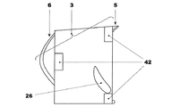
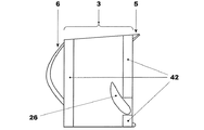
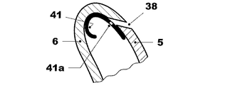
図4および4aには三つの担持リブにより境界を定められた根元部3を備えた別の実施例が示してあり、図4cには担持リブ42により境界を定められた根元部3を備えた別の実施例が示してある。
4 and 4a show another embodiment with a
図6にはすでに説明したブレードに似たブレード1の実施例が示してあり、これに関して同じ参照符号を図6で使用して、同じかもしくは似た部材の境界を定めている。
FIG. 6 shows an embodiment of a
特に図6のブレードは図1のブレードとほぼ同じ特徴を有しているが、シュラウド10は備えていない。説明した特徴が互いに独立して設けられているのは当然である。このようにして考案された(ロータブレードおよび/またはガイドベーン(すなわちステータブレード)である)タービンブレードは、数多くの修正および変更を受入れる余地があり、すべて創意に富んだ構想の範囲内に入っており、さらに詳細はすべて技術的に同等な部材により置き換えることだできる。
In particular, the blade of FIG. 6 has substantially the same features as the blade of FIG. 1, but does not include the
実際に、使用される材料ならびに寸法は要求と従来技術に応じて自由に選定できる。 In practice, the materials and dimensions used can be freely selected according to requirements and prior art.
1 タービンブレード
2 プラットフォーム
3 根元部
5 翼形部分
6 翼形部分
7 5の作動面
8 6の作動面
10 シュラウド
11 流路
14 5の内側面
15 6の内側面
17 熱伝達促進体
18 スペーサ
20 貫通孔
22 ブレード担持体
24 翼形
25 空間
26 孔
27 管状インサート
28 根元部の領域
30 スペーサ
31 調節された貫通孔
32 スロット
33 板
34 封隙部
35 ケーシング
38 前縁部における間隙
39 後縁部における間隙
40 段付部分
41 バネ
41a 貫通孔
42 担持リブ
DESCRIPTION OF
Claims (16)
前記プラットフォーム(2)の反対の周方向の側から、翼形部分(5,6)が延びており、
一方の作動面(7,8)の境界を定めている前記翼形部分が各々他方の翼形部分(6,5)に面している面であり、
前記翼形部分(5,6)の一つの作動面(7,8)が、吸引側の境界を定めており、翼形部分の他方の作動面が圧力側の境界を定めており、組立てられた場合、互いに接続された2つの異なる隣接するブレード(1)の2つの翼形部分(5)および(6)が翼形(24)を形成し、
前記翼形部分(5,6)の少なくとも一つの内側面(14,15)が、多数のブレード(1)がブレード担持体(22)上に組立てられた場合、スペーサ(18,30)が二つの隣接した翼形部分(5,6)の間に挿入されているように、スペーサ(18,30)を備えていることを特徴とするブレード(1)。 In a blade (1) comprising at least one root (3) arranged to be connected to a platform (2) and a blade carrier (22),
An airfoil portion (5, 6) extends from the opposite circumferential side of the platform (2),
The airfoil portions defining the boundary of one working surface (7, 8) are each facing the other airfoil portion (6, 5);
One working surface (7, 8) of the airfoil portion (5, 6) delimits the suction side and the other working surface of the airfoil portion delimits the pressure side and is assembled. The two airfoil portions (5) and (6) of two different adjacent blades (1) connected to each other form an airfoil (24) ,
When at least one inner surface (14, 15) of the airfoil portion (5, 6) is assembled with a number of blades (1) on the blade carrier (22), two spacers (18, 30) are provided. Blade (1) characterized in that it is provided with spacers (18, 30) so as to be inserted between two adjacent airfoil parts (5, 6 ).
翼形部分(5,6)を備えたプラットフォーム(2)とシュラウド(10)が閉鎖した流路(11)の境界を定めていることを特徴とする請求項1〜3のいずれか一つに記載のブレード(1)。 A shroud (10) connected to both ends of the airfoil portion (5, 6);
To claim 1-3, characterized in that defines the boundaries of the platform with an airfoil portion (5, 6) (2) and the shroud (10) a flow path which is closed (11) The blade (1) described.
Applications Claiming Priority (2)
| Application Number | Priority Date | Filing Date | Title |
|---|---|---|---|
| EP20090177829 EP2333240B1 (en) | 2009-12-03 | 2009-12-03 | Two-part turbine blade with improved cooling and vibrational characteristics |
| EP09177829.0 | 2009-12-03 |
Publications (3)
| Publication Number | Publication Date |
|---|---|
| JP2011122588A JP2011122588A (en) | 2011-06-23 |
| JP2011122588A5 JP2011122588A5 (en) | 2015-02-26 |
| JP5777330B2 true JP5777330B2 (en) | 2015-09-09 |
Family
ID=42126048
Family Applications (1)
| Application Number | Title | Priority Date | Filing Date |
|---|---|---|---|
| JP2010268897A Expired - Fee Related JP5777330B2 (en) | 2009-12-03 | 2010-12-02 | Turbine blade |
Country Status (4)
| Country | Link |
|---|---|
| US (1) | US9017035B2 (en) |
| EP (1) | EP2333240B1 (en) |
| JP (1) | JP5777330B2 (en) |
| CN (1) | CN102102542B (en) |
Families Citing this family (14)
| Publication number | Priority date | Publication date | Assignee | Title |
|---|---|---|---|---|
| FR2984786B1 (en) * | 2011-12-23 | 2014-01-03 | Snecma | METHOD FOR MANUFACTURING A HOLLOW DAWN |
| JP2013213427A (en) * | 2012-04-02 | 2013-10-17 | Toshiba Corp | Hollow nozzle and manufacturing method thereof |
| JP2015527530A (en) * | 2012-08-20 | 2015-09-17 | アルストム テクノロジー リミテッドALSTOM Technology Ltd | Internally cooled wings for rotating machinery |
| CN103742203B (en) * | 2014-02-11 | 2016-04-27 | 上海电气电站设备有限公司 | Steam turbine final blade |
| US20160281517A1 (en) * | 2015-03-26 | 2016-09-29 | Solar Turbines Incorporated | Cast nozzle with split airfoil |
| WO2018044270A1 (en) * | 2016-08-30 | 2018-03-08 | Siemens Aktiengesellschaft | Segment for a turbine rotor stage |
| WO2018044271A1 (en) * | 2016-08-30 | 2018-03-08 | Siemens Aktiengesellschaft | Flow directing structure for a turbine stator stage |
| US10662782B2 (en) * | 2016-11-17 | 2020-05-26 | Raytheon Technologies Corporation | Airfoil with airfoil piece having axial seal |
| CN106593544A (en) * | 2017-01-23 | 2017-04-26 | 中国航发沈阳发动机研究所 | Tail edge cooling structure of turbine rotor blade and engine with tail edge cooling structure |
| GB201720828D0 (en) | 2017-12-14 | 2018-01-31 | Rolls Royce Plc | Aerofoil |
| GB201720829D0 (en) | 2017-12-14 | 2018-01-31 | Rolls Royce Plc | Aerofoil and method of manufacture |
| FR3108667B1 (en) * | 2020-03-27 | 2022-08-12 | Safran Ceram | Turbine stator blade made of ceramic matrix composite material |
| US11898463B2 (en) | 2021-03-29 | 2024-02-13 | Rtx Corporation | Airfoil assembly with fiber-reinforced composite rings |
| US11549378B1 (en) | 2022-06-03 | 2023-01-10 | Raytheon Technologies Corporation | Airfoil assembly with composite rings and sealing shelf |
Family Cites Families (17)
| Publication number | Priority date | Publication date | Assignee | Title |
|---|---|---|---|---|
| US2930580A (en) * | 1953-03-12 | 1960-03-29 | Gen Motors Corp | Two-piece turbine bucket |
| GB2028928B (en) | 1978-08-17 | 1982-08-25 | Ross Royce Ltd | Aerofoil blade for a gas turbine engine |
| JPH0510102A (en) | 1991-07-02 | 1993-01-19 | Hitachi Ltd | Gas turbine blade and gas turbine device |
| US5203873A (en) | 1991-08-29 | 1993-04-20 | General Electric Company | Turbine blade impingement baffle |
| CN1162345A (en) | 1994-10-31 | 1997-10-15 | 西屋电气公司 | Gas turbine blade with a cooled platform |
| JP3824324B2 (en) | 1994-10-31 | 2006-09-20 | ウエスチングハウス・エレクトリック・コーポレイション | Gas turbine blades with cooling platform |
| CA2262701C (en) * | 1997-06-06 | 2003-02-18 | Mitsubishi Heavy Industries, Ltd. | Gas turbine blade |
| JP4976614B2 (en) * | 1997-10-27 | 2012-07-18 | シーメンス エナジー インコーポレイテッド | Superalloy casting method |
| AU3698800A (en) * | 1999-03-11 | 2000-09-28 | Alm Development, Inc. | Turbine rotor disk |
| EP1191189A1 (en) * | 2000-09-26 | 2002-03-27 | Siemens Aktiengesellschaft | Gas turbine blades |
| US6382908B1 (en) * | 2001-01-18 | 2002-05-07 | General Electric Company | Nozzle fillet backside cooling |
| JP2003214107A (en) | 2002-01-25 | 2003-07-30 | Mitsubishi Heavy Ind Ltd | Axial flow turbine blade, gas turbine using the same and axial flow compressor |
| US6742991B2 (en) | 2002-07-11 | 2004-06-01 | Mitsubishi Heavy Industries, Ltd. | Turbine blade and gas turbine |
| US7094031B2 (en) * | 2004-09-09 | 2006-08-22 | General Electric Company | Offset Coriolis turbulator blade |
| JP2006242050A (en) * | 2005-03-02 | 2006-09-14 | Mitsubishi Heavy Ind Ltd | Blade cooling structure for gas turbine |
| US7371049B2 (en) * | 2005-08-31 | 2008-05-13 | United Technologies Corporation | Manufacturable and inspectable microcircuit cooling for blades |
| US7322796B2 (en) | 2005-08-31 | 2008-01-29 | United Technologies Corporation | Turbine vane construction |
-
2009
- 2009-12-03 EP EP20090177829 patent/EP2333240B1/en not_active Not-in-force
-
2010
- 2010-12-02 US US12/958,727 patent/US9017035B2/en not_active Expired - Fee Related
- 2010-12-02 JP JP2010268897A patent/JP5777330B2/en not_active Expired - Fee Related
- 2010-12-03 CN CN201010585344.5A patent/CN102102542B/en not_active Expired - Fee Related
Also Published As
| Publication number | Publication date |
|---|---|
| CN102102542A (en) | 2011-06-22 |
| JP2011122588A (en) | 2011-06-23 |
| US20110135497A1 (en) | 2011-06-09 |
| CN102102542B (en) | 2016-02-10 |
| EP2333240A1 (en) | 2011-06-15 |
| US9017035B2 (en) | 2015-04-28 |
| EP2333240B1 (en) | 2013-02-13 |
Similar Documents
| Publication | Publication Date | Title |
|---|---|---|
| JP5777330B2 (en) | Turbine blade | |
| JP6063731B2 (en) | Turbine rotor blade platform cooling | |
| JP6266231B2 (en) | Cooling structure at the tip of turbine rotor blade | |
| JP6192984B2 (en) | Cooling structure at the tip of turbine blade | |
| JP5947519B2 (en) | Apparatus and method for cooling the platform area of a turbine rotor blade | |
| JP6132546B2 (en) | Turbine rotor blade platform cooling | |
| JP5898898B2 (en) | Apparatus and method for cooling the platform area of a turbine rotor blade | |
| JP6209609B2 (en) | Moving blade | |
| JP4386891B2 (en) | Turbine blade having an inclined squealer tip | |
| JP5414200B2 (en) | Turbine rotor blade assembly and method of making the same | |
| JP5898901B2 (en) | Apparatus and method for cooling the platform area of a turbine rotor blade | |
| JP5898902B2 (en) | Apparatus and method for cooling a platform area of a turbine blade | |
| JP2017120085A (en) | Tip shrouded turbine rotor blades | |
| JP2014196735A5 (en) | ||
| JP2008111441A (en) | Turbomachine turbine shroud sector | |
| JP5965633B2 (en) | Apparatus and method for cooling the platform area of a turbine rotor blade | |
| JP5868609B2 (en) | Gas turbine blade and method for manufacturing the same | |
| US9657579B2 (en) | Cooled vane of a high-pressure turbine | |
| JP2008240725A (en) | Steam turbine | |
| US9528381B2 (en) | Structural configurations and cooling circuits in turbine blades | |
| JP6438662B2 (en) | Cooling passage of turbine blade of gas turbine engine | |
| JP2016121682A (en) | Rotary gas turbine blade and gas turbine with such blade | |
| JP2012132438A (en) | Apparatus and method for cooling platform region of turbine rotor blade | |
| JP5916294B2 (en) | Gas turbine blade and method for manufacturing the same | |
| US20150184521A1 (en) | Structural configurations and cooling circuits in turbine blades |
Legal Events
| Date | Code | Title | Description |
|---|---|---|---|
| RD03 | Notification of appointment of power of attorney |
Free format text: JAPANESE INTERMEDIATE CODE: A7423 Effective date: 20130628 |
|
| RD04 | Notification of resignation of power of attorney |
Free format text: JAPANESE INTERMEDIATE CODE: A7424 Effective date: 20130703 |
|
| A521 | Written amendment |
Free format text: JAPANESE INTERMEDIATE CODE: A523 Effective date: 20131107 |
|
| A621 | Written request for application examination |
Free format text: JAPANESE INTERMEDIATE CODE: A621 Effective date: 20131107 |
|
| A977 | Report on retrieval |
Free format text: JAPANESE INTERMEDIATE CODE: A971007 Effective date: 20140911 |
|
| A131 | Notification of reasons for refusal |
Free format text: JAPANESE INTERMEDIATE CODE: A131 Effective date: 20140916 |
|
| A601 | Written request for extension of time |
Free format text: JAPANESE INTERMEDIATE CODE: A601 Effective date: 20141216 |
|
| A602 | Written permission of extension of time |
Free format text: JAPANESE INTERMEDIATE CODE: A602 Effective date: 20141219 |
|
| A524 | Written submission of copy of amendment under section 19 (pct) |
Free format text: JAPANESE INTERMEDIATE CODE: A524 Effective date: 20150108 |
|
| TRDD | Decision of grant or rejection written | ||
| A01 | Written decision to grant a patent or to grant a registration (utility model) |
Free format text: JAPANESE INTERMEDIATE CODE: A01 Effective date: 20150608 |
|
| A61 | First payment of annual fees (during grant procedure) |
Free format text: JAPANESE INTERMEDIATE CODE: A61 Effective date: 20150707 |
|
| R150 | Certificate of patent or registration of utility model |
Ref document number: 5777330 Country of ref document: JP Free format text: JAPANESE INTERMEDIATE CODE: R150 |
|
| S533 | Written request for registration of change of name |
Free format text: JAPANESE INTERMEDIATE CODE: R313533 |
|
| R350 | Written notification of registration of transfer |
Free format text: JAPANESE INTERMEDIATE CODE: R350 |
|
| S111 | Request for change of ownership or part of ownership |
Free format text: JAPANESE INTERMEDIATE CODE: R313113 |
|
| R350 | Written notification of registration of transfer |
Free format text: JAPANESE INTERMEDIATE CODE: R350 |
|
| LAPS | Cancellation because of no payment of annual fees |