JP5773932B2 - Electric motor rotation information detection method, electric motor rotation information detection device, electric motor control device - Google Patents
Electric motor rotation information detection method, electric motor rotation information detection device, electric motor control device Download PDFInfo
- Publication number
- JP5773932B2 JP5773932B2 JP2012081905A JP2012081905A JP5773932B2 JP 5773932 B2 JP5773932 B2 JP 5773932B2 JP 2012081905 A JP2012081905 A JP 2012081905A JP 2012081905 A JP2012081905 A JP 2012081905A JP 5773932 B2 JP5773932 B2 JP 5773932B2
- Authority
- JP
- Japan
- Prior art keywords
- electric motor
- frequency
- ripple
- current
- waveform data
- Prior art date
- Legal status (The legal status is an assumption and is not a legal conclusion. Google has not performed a legal analysis and makes no representation as to the accuracy of the status listed.)
- Expired - Fee Related
Links
- 238000001514 detection method Methods 0.000 title claims description 33
- 238000004458 analytical method Methods 0.000 claims description 26
- 238000000034 method Methods 0.000 claims description 17
- 238000012937 correction Methods 0.000 claims description 14
- 238000001914 filtration Methods 0.000 claims description 9
- 238000000605 extraction Methods 0.000 claims description 2
- 238000012545 processing Methods 0.000 description 12
- 238000001228 spectrum Methods 0.000 description 11
- 230000006870 function Effects 0.000 description 10
- 238000010586 diagram Methods 0.000 description 7
- 238000013461 design Methods 0.000 description 6
- 238000004364 calculation method Methods 0.000 description 5
- 238000005070 sampling Methods 0.000 description 5
- 238000012887 quadratic function Methods 0.000 description 2
- 230000003247 decreasing effect Effects 0.000 description 1
- 238000002474 experimental method Methods 0.000 description 1
- 238000003672 processing method Methods 0.000 description 1
- 230000004044 response Effects 0.000 description 1
Images


Classifications
-
- H—ELECTRICITY
- H02—GENERATION; CONVERSION OR DISTRIBUTION OF ELECTRIC POWER
- H02P—CONTROL OR REGULATION OF ELECTRIC MOTORS, ELECTRIC GENERATORS OR DYNAMO-ELECTRIC CONVERTERS; CONTROLLING TRANSFORMERS, REACTORS OR CHOKE COILS
- H02P7/00—Arrangements for regulating or controlling the speed or torque of electric DC motors
- H02P7/0094—Arrangements for regulating or controlling the speed or torque of electric DC motors wherein the position is detected using the ripple of the current caused by the commutator
Description
本発明は、電動モータに流れる電流の変化に基づいて、電動モータの回転数や回転角といった回転情報を検出する方法および装置と、検出した回転情報に基づいて電動モータの回転を制御する装置に関する。 The present invention relates to a method and apparatus for detecting rotation information such as the rotation speed and rotation angle of an electric motor based on a change in current flowing in the electric motor, and an apparatus for controlling the rotation of the electric motor based on the detected rotation information. .
従来、エンコーダなどの外部検出手段を用いずに、駆動中の電動モータに流れる電流の変化に基づいて、電動モータの回転数などの回転情報を検出する方法および装置が提案されている。 2. Description of the Related Art Conventionally, there has been proposed a method and apparatus for detecting rotation information such as the number of rotations of an electric motor based on a change in a current flowing through the electric motor being driven without using an external detection means such as an encoder.
たとえば、特許文献1では、ブラシを備えた電動モータに流れる電流を検出して、この電流波形の周波数分析を行い、リプル(ripple:脈動電流)の周波数を抽出する。電動モータのブラシと摺接する整流子が切り替わる度に、電動モータに流れる電流にリプルが発生するため、リプル周波数と整流子数により、電動モータの回転数が求められる。
For example, in
また、特許文献2では、電動モータの入力電流波形を所定の間隔でサンプリングして、サンプリングデータを採取し、該データを時間軸方向に一定周期で順次シフトさせて複数のシフトサンプリングデータを作成する。そして、サンプリングデータと各シフトサンプリングデータの差分の絶対値の和の値を、一定周期でプロットして正規化電流波形を取得し、該波形を周波数分析して得た高調波の基本周波数に基づいて、電動モータの回転数を演算する。
In
電流などの変動値の時系列の波形データを、フーリエ変換などのアルゴリズムで周波数解析して、周波数の波形データに変換し、振幅の高い周波数を抽出することは、特許文献3に開示されているように、一般に行われている。特許文献3では、高いピークを有する周波数のゲインレベルの変動に基づいて、電動モータに結合された機械の故障を診断する。
ところで、駆動中の電動モータに流れる電流には、リプル以外に、外部要因や電動モータの機械的なばらつきなどに起因したノイズが発生することがある。このため、電流波形を周波数解析して得た波形で、ノイズの周波数の振幅がリプルの周波数の振幅と同様に、他より大きく突出して、ノイズの周波数をリプルの周波数として誤検出してしまうおそれがある。このように誤検出した周波数では、電動モータの回転情報を精度よく検出することができない。 Incidentally, in the current flowing through the electric motor being driven, noise due to external factors and mechanical variations of the electric motor may occur in addition to ripple. For this reason, in the waveform obtained by frequency analysis of the current waveform, the amplitude of the noise frequency may protrude more greatly than the ripple frequency, and the noise frequency may be erroneously detected as the ripple frequency. There is. Thus, the rotation information of the electric motor cannot be accurately detected at the erroneously detected frequency.
本発明の課題は、ノイズの影響を低減して、電動モータの回転情報を精度よく検出することである。 An object of the present invention is to reduce the influence of noise and accurately detect rotation information of an electric motor.
本発明では、ブラシを備えた電動モータに流れる電流を検出し、該電流に発生するリプルの周波数に基づいて、電動モータの回転情報を検出する電動モータの回転情報検出方法において、電動モータに流れる電流の時系列波形データを周波数解析して、得られた周波数単位の波形データの所定の低域にある極大値を有する、モータ電流の基本波の周波数を基本周波数候補とし、電動モータの整流子数と電動モータに流れる電流の変化特性とに基づいて予め設定された係数を、基本周波数候補に乗じて、リプル周波数候補を算出し、周波数単位の波形データでリプル周波数候補の両隣にある極大値を有する周波数をリプル周波数候補として追加し、リプル周波数候補の最大振幅が所定のしきい値以上である場合に、該最大振幅を有するリプル周波数候補をリプル周波数とする。 According to the present invention, in a rotation information detection method for an electric motor that detects current flowing in an electric motor equipped with a brush and detects rotation information of the electric motor based on a frequency of a ripple generated in the current, the electric current flows in the electric motor. Frequency analysis of current time-series waveform data, the frequency of the fundamental wave of the motor current having a maximum value in a predetermined low frequency of the obtained waveform data in frequency units is set as the fundamental frequency candidate, and the commutator of the electric motor The ripple frequency candidate is calculated by multiplying the fundamental frequency candidate by a coefficient set in advance based on the number and the change characteristic of the current flowing through the electric motor, and the maximum value that is adjacent to the ripple frequency candidate is calculated using waveform data in frequency units. Is added as a ripple frequency candidate, and when the maximum amplitude of the ripple frequency candidate is equal to or greater than a predetermined threshold value, the ripple frequency having the maximum amplitude is The number candidates to the ripple frequency.
また、本発明では、ブラシを備えた電動モータに流れる電流を検出する電流検出手段を備え、電動モータに流れる電流に発生するリプルの周波数に基づいて、電動モータの回転情報を検出する電動モータの回転情報検出装置において、さらに、電流検出手段により検出した電流の時系列波形データを周波数解析する解析手段と、リプル周波数を推定する推定手段とを備える。推定手段は、解析手段による周波数解析で得られた周波数単位の波形データの所定の低域にある極大値を有する、モータ電流の基本波の周波数を基本周波数候補とし、電動モータの整流子数と電動モータに流れる電流の変化特性とに基づいて予め設定された係数を、基本周波数候補に乗じて、リプル周波数候補を算出し、周波数単位の波形データでリプル周波数候補の両隣にある極大値を有する周波数をリプル周波数候補として追加し、リプル周波数候補の最大振幅が所定のしきい値以上である場合に、該最大振幅を有するリプル周波数候補をリプル周波数と推定する。 Further, in the present invention, there is provided a current detection means for detecting a current flowing in the electric motor provided with the brush, and the electric motor detects the rotation information of the electric motor based on the frequency of the ripple generated in the current flowing in the electric motor. The rotation information detection apparatus further includes an analysis unit that performs frequency analysis on the time-series waveform data of the current detected by the current detection unit, and an estimation unit that estimates the ripple frequency. The estimation means uses the frequency of the fundamental wave of the motor current having a local maximum value in a predetermined low range of the waveform data in frequency units obtained by the frequency analysis by the analysis means as a fundamental frequency candidate, and the number of commutators of the electric motor The ripple frequency candidate is calculated by multiplying the fundamental frequency candidate by a coefficient set in advance based on the change characteristic of the current flowing through the electric motor, and has a maximum value on both sides of the ripple frequency candidate in the frequency unit waveform data. A frequency is added as a ripple frequency candidate, and when the maximum amplitude of the ripple frequency candidate is greater than or equal to a predetermined threshold, the ripple frequency candidate having the maximum amplitude is estimated as the ripple frequency.
また、本発明では、ブラシを備えた電動モータに流れる電流を検出する電流検出手段を備え、電動モータに流れる電流に発生するリプルの周波数に基づいて、電動モータの回転情報を検出し、該回転情報に基づいて電動モータの駆動を制御する電動モータ制御装置において、さらに、前記解析手段と前記推定手段とを備える。 The present invention also includes current detection means for detecting the current flowing through the electric motor provided with the brush, and detects rotation information of the electric motor based on the frequency of the ripple generated in the current flowing through the electric motor. The electric motor control apparatus that controls the driving of the electric motor based on the information further includes the analysis means and the estimation means.
上記によると、電動モータの電流の時系列波形データを周波数解析して得られた周波数単位の波形データにおいて、低域にある基本周波数とほぼ比例関係にあるリプル周波数を確実に検出することができる。このため、ノイズの影響を低減して、リプル周波数に基づいて、電動モータの回転情報を精度よく検出することができる。また、精度よく検出した電動モータの回転情報に基づいて、電動モータの回転を適切に制御することができる。 According to the above, in the frequency unit waveform data obtained by frequency analysis of the time series waveform data of the electric motor current, it is possible to reliably detect the ripple frequency that is substantially proportional to the fundamental frequency in the low band. . For this reason, the influence of noise can be reduced and the rotation information of the electric motor can be accurately detected based on the ripple frequency. Further, the rotation of the electric motor can be appropriately controlled based on the rotation information of the electric motor detected with high accuracy.
また、本発明では、上記電動モータの回転情報検出方法において、電動モータに流れる電流の時系列波形データを周波数解析する前に、電流の時系列波形データの近似関数を算出して、該近似関数に基づいて電流の時系列波形データの傾向を補正してもよい。 Further, in the present invention, in the rotation information detection method for the electric motor, before performing frequency analysis on the time series waveform data of the current flowing through the electric motor, an approximate function of the time series waveform data of the current is calculated, and the approximation function The trend of the current time-series waveform data may be corrected based on the above.
また、本発明では、上記電動モータの回転情報検出装置において、さらに、解析手段により電動モータに流れる電流の時系列波形データを周波数解析する前に、電流の時系列波形データの近似関数を算出して、該近似関数に基づいて電流の時系列波形データの傾向を補正する補正手段を備えてもよい。 In the present invention, the rotation information detecting device for the electric motor further calculates an approximate function of the current time-series waveform data before performing frequency analysis of the time-series waveform data of the current flowing through the electric motor by the analyzing means. Then, a correction means for correcting the tendency of the current time-series waveform data based on the approximate function may be provided.
また、本発明では、上記電動モータの回転情報検出方法において、リプル周波数に基づいてフィルタ係数を算出し、電動モータに流れる電流の時系列波形データをフィルタ係数でフィルタリング処理して、リプル電流の時系列波形データを抽出し、リプル電流の時系列波形データからリプルパルス信号を生成してもよい。 According to the present invention, in the method for detecting rotation information of the electric motor, the filter coefficient is calculated based on the ripple frequency, the time-series waveform data of the current flowing through the electric motor is filtered by the filter coefficient, and the ripple current is detected. The series waveform data may be extracted, and the ripple pulse signal may be generated from the time series waveform data of the ripple current.
また、本発明では、上記電動モータの回転情報検出装置において、さらに、推定手段により推定したリプル周波数に基づいてフィルタ係数を算出する算出手段と、電動モータに流れる電流の時系列波形データをフィルタ係数でフィルタリング処理して、リプル電流の時系列波形データを抽出する抽出手段と、リプル電流の時系列波形データからリプルパルス信号を生成する生成手段とを備えてもよい。 According to the present invention, in the rotation information detection apparatus for the electric motor, the calculation means for calculating the filter coefficient based on the ripple frequency estimated by the estimation means, and the time series waveform data of the current flowing through the electric motor are filtered. Filtering means for extracting ripple current time-series waveform data and generating means for generating ripple pulse signals from the ripple current time-series waveform data.
本発明によれば、ノイズの影響を受けずに、リプル周波数を確実に検出して、電動モータの回転情報を精度よく検出することができる。また、精度よく検出した回転情報に基づいて、電動モータの回転を適切に制御することができる。 According to the present invention, it is possible to reliably detect the ripple frequency and accurately detect the rotation information of the electric motor without being affected by noise. Moreover, the rotation of the electric motor can be appropriately controlled based on the rotation information detected with high accuracy.
以下、本発明の実施形態につき、図面を参照しながら説明する。各図において、同一の部分または対応する部分には、同一符号を付してある。 Hereinafter, embodiments of the present invention will be described with reference to the drawings. In the drawings, the same or corresponding parts are denoted by the same reference numerals.
まず、本発明の一実施形態による電動モータ制御装置100の構成を、図1を参照しながら説明する。 First, the configuration of an electric motor control device 100 according to an embodiment of the present invention will be described with reference to FIG.
電動モータ制御装置100の制御部1は、マイクロコンピュータから成る。モータ駆動部2は、1対のリレーまたは4つのスイッチング素子を備えた開閉回路から成る。制御部1は、モータ駆動部2を動作させて、バッテリ5から電動モータ4に電流を流して、電動モータ4を回転させる。
The
電動モータ4は、ブラシと整流子を備えたDCモータから成る。制御部1は、電動モータ4の動力により、駆動対象物30を動作させる。たとえば、駆動対象物30は、車両のパワーウインドウであり、電動モータ制御装置100は、パワーウインドウ用のECU(電子制御装置)である。
The
電流検出部3は、電動モータ4に流れるモータ電流を所定周期で検出して、制御部1に出力する。電動モータ4の駆動中、電動モータ4のブラシと摺接する整流子が切り替わる度に、モータ電流にリプル(ripple:脈動電流)が発生する。制御部1の回転情報検出部10は、後述するように、モータ電流のリプルの周波数に基づいて、電動モータ4の回転数と回転角などの回転情報を検出する。
The
電動モータ制御装置100は、本発明の「電動モータの回転情報検出装置」の一例である。電流検出部3は、本発明の「電流検出手段」の一例である。
The electric motor control device 100 is an example of the “electric motor rotation information detection device” in the present invention. The
制御部1の位置検出部20は、回転情報検出部10で検出された電動モータ4の回転角に基づいて、駆動対象物30の動作位置を検出する。制御部1は、回転情報検出部10で検出された回転数に基づいて、モータ駆動部2を動作させて、電動モータ4の回転速度を制御する。また、制御部1は、回転情報検出部10で検出された回転角や、位置検出部20で検出された動作位置に基づいて、モータ駆動部2を動作させて、電動モータ4の回転量や、駆動対象物30の動作量を制御する。
The
次に、本発明の一実施形態による電動モータ4の回転情報検出方法を、図2〜図13を参照しながら説明する。本方法を実行するのは、電動モータ制御装置100の制御部1である。
Next, a method for detecting rotation information of the
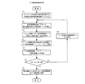
制御部1には、図2に示すような、電動モータ4の回転情報検出用の制御ブロック11〜16が設けられている。これらのブロックの各機能は、実際にはソフトウェアによって実現されるが、ハードウェアで実現してもよい。図1の電流検出部3で検出された電動モータ4のモータ電流値は、随時、制御部1に入力されて、制御部1の内蔵メモリに所定数保存される。そして、所定サンプル数のモータ電流値が時系列波形データとして、図2の傾向補正ブロック11に入力される。傾向補正ブロック11は、本発明の「補正手段」の一例である。
The
傾向補正ブロック11では、図3(a)に示す2次関数近似ブロック11aで、図3(b)に示すようなモータ電流の時系列波形データを、最小二乗法により2次関数で近似して、図3(c)に示すような近似データを算出する。そして、モータ電流の時系列波形データの各値から、近似データの各値を減算して、モータ電流の時系列波形データの傾向を補正する。
The
これにより、たとえば、図3(b)に示すように波形全体にわたって下降および上昇の度合いが大きかったモータ電流の時系列波形データは、図3(d)に示すように下降および上昇の度合いが抑えられた波形データとなる。傾向補正後のモータ電流の時系列波形データは、傾向補正ブロック11から、図2のFFT(高速フーリエ変換)ブロック12へ出力される。FFTブロック12は、本発明の「解析手段」の一例である。
As a result, for example, the time series waveform data of the motor current having a large degree of decrease and increase over the entire waveform as shown in FIG. 3 (b) suppresses the degree of decrease and increase as shown in FIG. 3 (d). Waveform data. The time series waveform data of the motor current after the trend correction is output from the
FFTブロック12では、傾向補正後のモータ電流の時系列波形データを、FFTにより周波数解析する。これにより、図4(b)に示すような傾向補正後のモータ電流の時系列波形データが、たとえば図4(c)に示すような周波数のスペクトル(周波数単位の波形データ)に変換される。
The
周波数解析により得られたスペクトルは、FFTブロック12から、図2のリプル周波数推定ブロック13へ出力される。リプル周波数推定ブロック13は、本発明の「推定手段」の一例である。
The spectrum obtained by the frequency analysis is output from the
リプル周波数推定ブロック13では、まず、図6に示すように、スペクトルの所定の低域にある、極大値を有する周波数を全て基本周波数候補Fbとする(図5のステップS1)。次に、基本周波数候補Fbのうち、最大振幅を有する周波数Fbmを検出する(図5のステップS2)。そして、その周波数Fbmに所定の係数Kを乗じて、リプル周波数候補Frbを算出する(ステップS3)。
In the ripple
係数Kは、電動モータ4に備わる整流子の数Rと、電動モータ4に流れる電流の変化特性とに基づいて、予め設定されている。具体的には、整流子の数Rを、回転子が1回転したときに電動モータ4に流れた電流の時系列波形データの基本波の数Bで除した値を、係数Kとして設定している(係数K=整流子数R/基本波数B)。
The coefficient K is set in advance based on the number R of commutators provided in the
たとえば、電動モータ4に備わる整流子が8つあって、電動モータ4の回転子が1回転したときのモータ電流の時系列波形データが、図7に実線で示すように変化した場合、リプルは8つ発生している。これは、電動モータ4の回転子が1回転したときに、ブラシと摺接する整流子が8回切り替わって、その度にブラシと整流子の間で電流の流れ方(大小)が変化するからである。
For example, if the
また、図7では、8つのリプルが発生する間に、リプルが重畳されたモータ電流の大きな基本波は、破線で示すように2つ(2周期)発生している。この場合、整流子数R=8を、基本波数B=2で除して、係数K=4となる(係数K=整流子数R/基本波数B=8/2=4)。つまり、係数Kは、電動モータ4の整流子数R(=1回転あたりのリプル数)と基本波数Bの比である。
Further, in FIG. 7, while the eight ripples are generated, two large fundamental waves of the motor current on which the ripples are superimposed are generated (two cycles) as indicated by a broken line. In this case, the number of commutators R = 8 is divided by the fundamental wave number B = 2 to obtain a coefficient K = 4 (coefficient K = commutator number R / fundamental wave number B = 8/2 = 4). That is, the coefficient K is the ratio of the commutator number R (= ripple number per rotation) of the
図7に示すようなモータ電流の時系列波形データを、FFTにより周波数解析すると、図8に示すようなスペクトルが得られる。図8において、低域にある極大値を有する周波数は、モータ電流の基本波の周波数、つまり基本周波数である。そして、高域で最大振幅の極大値を有する周波数は、リプル周波数である。リプル周波数は、基本周波数の約4倍になっている。つまり、リプル周波数は基本周波数の約係数K倍であり、リプル周波数と基本周波数はほぼ比例関係にある。 When frequency analysis is performed on the time series waveform data of the motor current as shown in FIG. 7 by FFT, a spectrum as shown in FIG. 8 is obtained. In FIG. 8, the frequency having the maximum value in the low band is the frequency of the fundamental wave of the motor current, that is, the fundamental frequency. And the frequency which has the maximum value of the maximum amplitude in a high region is a ripple frequency. The ripple frequency is about four times the fundamental frequency. That is, the ripple frequency is approximately K times the fundamental frequency, and the ripple frequency and the fundamental frequency are approximately proportional.
電動モータ4の整流子数Rは、たとえば電動モータ4の仕様書などに開示されている。電動モータ4の1回転あたりの基本波数Bは、電動モータ4毎に異なるため、たとえば予め実験により計測しておく。
The number of commutators R of the
上記のようなデータの特性に着目して、図5のステップS3では、基本周波数候補Fbmを係数K倍して、リプル周波数候補Frbを算出している。 Focusing on the data characteristics as described above, in step S3 of FIG. 5, the fundamental frequency candidate Fbm is multiplied by a coefficient K to calculate the ripple frequency candidate Frb.
また、図5のステップS1で、基本周波数候補Fbを検出するスペクトルの低域(図5のステップS1、図6、図8)は、電動モータ4の使用領域に、電動モータ4の1回転あたりの基本波数Bを乗じた値以下の範囲に設定されている。たとえば、電動モータ4の使用領域が50Hzで、基本波数Bが2の場合、50Hz×2=100Hzであるため、上記低域は0〜100Hzとなる。
In addition, in the step S1 of FIG. 5, the low range of the spectrum for detecting the fundamental frequency candidate Fb (step S1, FIG. 6 and FIG. 8 of FIG. 5) Is set to a range equal to or less than the value multiplied by the fundamental wave number B. For example, when the use area of the
図5のステップS3でリプル周波数候補Frbを算出すると、図6に示すように、スペクトルでリプル周波数候補Frbの両隣にある極大値を有する周波数をリプル周波数候補Frr、Frlとして追加する(図5のステップS4)。そして、これらリプル周波数候補Frb、Frr、Frlの各振幅のうち、最大振幅Amを検出し(ステップS5)、該最大振幅Amが所定のしきい値以上か否かを判定する(ステップS6)。 When the ripple frequency candidate Frb is calculated in step S3 of FIG. 5, as shown in FIG. 6, the frequencies having the maximum values adjacent to the ripple frequency candidate Frb in the spectrum are added as ripple frequency candidates Frr and Frl (FIG. 5). Step S4). Then, the maximum amplitude Am is detected from the amplitudes of these ripple frequency candidates Frb, Frr, and Frl (step S5), and it is determined whether or not the maximum amplitude Am is equal to or greater than a predetermined threshold value (step S6).
ここで、最大振幅Amが所定のしきい値以上であれば(ステップS6:YES)、最大振幅Amを有するリプル周波数候補Frb、Frr、Frlをリプル周波数と推定する(ステップS7)。図6の例では、リプル周波数候補Frb、Frr、Frlのうち、リプル周波数候補Frlの振幅が最大で、かつ、しきい値以上であるため、リプル周波数候補Frlをリプル周波数と推定する。 If the maximum amplitude Am is greater than or equal to a predetermined threshold (step S6: YES), the ripple frequency candidates Frb, Frr, Frl having the maximum amplitude Am are estimated as ripple frequencies (step S7). In the example of FIG. 6, since the amplitude of the ripple frequency candidate Frl among the ripple frequency candidates Frb, Frr, and Frl is the maximum and equal to or greater than the threshold value, the ripple frequency candidate Frl is estimated as the ripple frequency.
一方、最大振幅Amが所定のしきい値未満であれば(図5のステップS6:NO)、周波数Fbmを基本周波数候補Fbから除外する(ステップS8)。そして、ステップS2以降の処理を再び実行する。 On the other hand, if the maximum amplitude Am is less than the predetermined threshold (step S6 in FIG. 5: NO), the frequency Fbm is excluded from the fundamental frequency candidates Fb (step S8). And the process after step S2 is performed again.
リプル周波数推定ブロック13で推定されたリプル周波数は、リプル周波数推定ブロック13から、図2のバンドパスフィルタ設計ブロック14へ出力される。バンドパスフィルタ設計ブロック14は、本発明の「算出手段」の一例である。
The ripple frequency estimated by the ripple
バンドパスフィルタ設計ブロック14では、図9に示すように、入力されたリプル周波数に基づいて、ブロック14aで低域側のエッジ周波数を設定し、ブロック14bで高域側のエッジ周波数を設定する。詳しくは、リプル周波数を所定比率C%増減した値を、それぞれ高域側と低域側のエッジ周波数とする。
リプル周波数+(リプル周波数のC%)=高域側のエッジ周波数
リプル周波数−(リプル周波数のC%)=低域側のエッジ周波数
In the bandpass
Ripple frequency + (C% of ripple frequency) = High frequency side edge frequency Ripple frequency-(Cripple frequency C%) = Low frequency side edge frequency
そして、ブロック14cで低域側と高域側のエッジ周波数に基づいて、バンドパスフィルタ係数を計算する。具体的には、窓関数法による一般的なFIR(有限インパルス応答)フィルタを設計して、各フィルタ係数を算出する。以下、手順を説明する。
Then, a band pass filter coefficient is calculated in
低域側のエッジ周波数Flと高域側のエッジ周波数Fhを設定した後、サンプリング周波数Fsで正規化したエッジ角周波数ωl、ωhを決定する。
ωl=2πFl/Fs、ωh=2πFh/Fs
次に、ωc=(ωh−ωl)/2をカットオフ角周波数とするローパスフィルタHl(n)を設計する。
Hl(n)=sin(n×ωc)/πn (n=0、±1、・・・、±M)
次に、窓関数W(n)を乗じる。
Hlw(n)=Hl(n)×W(n)
そして、以下の関係式を用いて、バンドパスフィルタのフィルタ係数Hbp(n)を算出する。
ω0=(ωl+ωh)/2
Hbp(n)=2cos(n×ω0)×Hlw(n)
After setting the edge frequency Fl on the low frequency side and the edge frequency Fh on the high frequency side, the edge angular frequencies ωl and ωh normalized by the sampling frequency Fs are determined.
ωl = 2πFl / Fs, ωh = 2πFh / Fs
Next, a low-pass filter Hl (n) having a cutoff angular frequency of ωc = (ωh−ωl) / 2 is designed.
Hl (n) = sin (n × ωc) / πn (n = 0, ± 1,..., ± M)
Next, the window function W (n) is multiplied.
Hlw (n) = Hl (n) × W (n)
Then, the filter coefficient Hbp (n) of the bandpass filter is calculated using the following relational expression.
ω0 = (ωl + ωh) / 2
Hbp (n) = 2 cos (n × ω0) × Hlw (n)
算出されたフィルタ係数は、バンドパスフィルタ設計ブロック14から、図2のフィルタリング処理ブロック15へ出力される。フィルタリング処理ブロック15は、本発明の「抽出手段」の一例である。
The calculated filter coefficients are output from the bandpass
フィルタリング処理ブロック15では、入力されたフィルタ係数で、モータ電流の時系列波形データをフィルタリング処理して、リプル電流の時系列波形データを抽出する。詳しくは、図10(a)に示すフィルタ演算ブロック15aで、入力されたフィルタ係数を用いた一般的なFIRフィルタ演算を行うことにより、図10(b)に示すようなモータ電流の時系列波形データから、図10(c)に示すようなリプル電流だけの時系列波形データを抽出する。
The
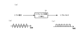
抽出されたリプル電流の時系列波形データは、フィルタリング処理ブロック15から、図2のリプルパルス処理ブロック16へ出力される。リプルパルス処理ブロック16は、本発明の「生成手段」の一例である。
The extracted time-series waveform data of the ripple current is output from the
リプルパルス処理ブロック16では、図11(b)に示すようなリプル電流の時系列波形データを、二値化処理して、図11(c)に示すような矩形波のリプルパルス信号を生成する。
The ripple
詳しくは、図12および図13に示すように、リプル電流の時系列波形データの時系列を追って、極小値を検出し、かつ、その極小値が所定の−(マイナス)側の不感帯しきい値以下であり、かつ、前回のリプルパルスが「High」(高レベル)であれば(ステップS11:YES)、リプルパルスを「Low」(低レベル)とする(ステップS12)。また、極大値を検出し、かつ、その極大値が所定の+(プラス)側の不感帯しきい値以上であり、かつ、前回のリプルパルスが「Low」であれば(ステップS13:YES)、リプルパルスを「High」とする(ステップS14)。 Specifically, as shown in FIGS. 12 and 13, a minimum value is detected following the time series of time series waveform data of the ripple current, and the minimum value is a predetermined negative band threshold value on the minus side. If the previous ripple pulse is “High” (high level) (step S11: YES), the ripple pulse is set to “Low” (low level) (step S12). Further, if the local maximum value is detected, the local maximum value is equal to or greater than the predetermined positive (+) dead zone threshold, and the previous ripple pulse is “Low” (step S13: YES), the ripple pulse is detected. Is set to “High” (step S14).
なお、初回は、たとえば、リプル電流の時系列波形データで、極小値を検出し、かつ、その極小値が所定の−側の不感帯しきい値以下であれば、リプルパルスを「Low」とする。また、極大値を検出し、かつ、その極大値が所定の+側の不感帯しきい値以上であれば、リプルパルスを「High」とする。 For the first time, for example, when a minimum value is detected from time-series waveform data of a ripple current and the minimum value is equal to or smaller than a predetermined negative-side dead band threshold, the ripple pulse is set to “Low”. If the maximum value is detected and the maximum value is equal to or greater than a predetermined positive-side dead band threshold, the ripple pulse is set to “High”.
上記により生成されたリプルパルス信号は、リプルパルス処理ブロック16から、図1の回転情報検出部10へ出力される。
The ripple pulse signal generated as described above is output from the ripple
回転情報検出部10は、入力されたリプルパルス信号に基づいて、電動モータ4の回転数と回転角などの回転情報を検出する。たとえば、回転数は、電動モータ4の整流子数と単位時間あたりのパルス数とに基づいて算出したり、1パルスの幅の逆数を算出したりする。回転角は、基点からのパルス数に基づいて算出する。回転情報検出部10は、リプルパルス信号から複数時点の回転情報を連続して検出する。
The rotation information detection unit 10 detects rotation information such as the rotation speed and rotation angle of the
図2のリプル周波数推定ブロック13で推定されたリプル周波数からも、電動モータ4の回転数を演算することができる(回転数=リプル周波数/電動モータ4の極数×60)。この場合は、一時点の回転数が検出される。
The number of rotations of the
傾向補正ブロック11とFFTブロック12を経てから、リプル周波数推定ブロック13でリプル周波数を推定するのにかかる時間より、回転情報検出部10で、リプルパルス信号から各時点の電動モータ4の回転情報を検出するのにかかる時間の方が、短くなっている。
From the time taken for the ripple
上記実施形態によると、電動モータ4の電流の時系列波形データをFFTで周波数解析して得られた周波数のスペクトルにおいて、低域にある基本周波数とほぼ比例関係にあるリプル周波数を確実に検出することができる。このため、図6に破線で示すように、リプル周波数候補でない振幅の大きいノイズがモータ電流に発生しても、ノイズの周波数をリプル周波数と誤検出するのを防止することができる。
According to the above embodiment, in the frequency spectrum obtained by frequency analysis of the time-series waveform data of the current of the
よって、ノイズの影響を受けずに、リプル周波数に基づいて、電動モータ4の回転情報を精度よく検出することができる。また、精度よく検出した電動モータ4の回転情報に基づいて、電動モータ4の回転を適切に制御することができる。
Therefore, the rotation information of the
ところで、電動モータ4の動き始めや停止直前では、電動モータ4の電流が上昇傾向や下降傾向になる。このため、そのときのモータ電流の時系列波形データをFFTで周波数解析すると、得られた周波数のスペクトルの低域で極大値が顕著に出ず、基本周波数候補Fbを検出できないおそれがある。
By the way, just before the
然るに、上記実施形態では、傾向補正ブロック11で、モータ電流の時系列波形データの傾向を近似関数(2次関数)により補正してから、FFTブロック12で周波数解析している。このため、FFTで得られた周波数のスペクトルの低域で極大値を顕著に出して、基本周波数候補Fbを確実に検出することができる。
However, in the above embodiment, the
さらに、上記実施形態では、リプル周波数に基づいて、リプル電流の時系列波形データを抽出し、該波形データからリプルパルス信号を生成している。このため、リプルパルス信号から電動モータ4の回転数と回転角を複数時点で連続して検出することができる。また、リプル周波数から電動モータ4の回転数を直接演算するより、リプルパルス信号から電動モータ4の回転数などを検出する方が、検出の精度と分解能を上げることができる。
Further, in the above embodiment, time series waveform data of the ripple current is extracted based on the ripple frequency, and a ripple pulse signal is generated from the waveform data. For this reason, the rotation speed and rotation angle of the
本発明は、上述した以外にも種々の実施形態を採用することができる。たとえば、上記実施形態では、モータ電流の時系列波形データをFFTで周波数解析した例を示したが、本発明はこれに限定するものではなく、DFT(離散フーリエ変換)などの他のアルゴリズムで周波数解析するようにしてもよい。 The present invention can employ various embodiments other than those described above. For example, in the above-described embodiment, an example in which the frequency analysis of the time series waveform data of the motor current is performed by FFT is shown. However, the present invention is not limited to this, and the frequency is calculated by other algorithms such as DFT (Discrete Fourier Transform). You may make it analyze.
また、上記実施形態では、リプル周波数に基づいて窓関数法によるFIRフィルタを設計して、バンドパスフィルタ係数を算出し、FIRフィルタ演算によりモータ電流の時系列データからリプルパルス電流の時系列データを抽出した例を示したが、本発明はこれに限定するものではない。これ以外のリプル周波数に基づく信号処理方法により、モータ電流の時系列データからリプルパルス電流の時系列データを抽出するようにしてもよい。 Further, in the above embodiment, an FIR filter based on the window function method is designed based on the ripple frequency, the band pass filter coefficient is calculated, and the time series data of the ripple pulse current is extracted from the time series data of the motor current by the FIR filter calculation. However, the present invention is not limited to this example. The time series data of the ripple pulse current may be extracted from the time series data of the motor current by a signal processing method based on a ripple frequency other than this.
さらに、上記実施形態では、パワーウインドウ用のECUから成る電動モータ制御装置100に本発明を適用した例を示したが、これ以外のブラシを備えた電動モータの回転情報が必要な種々の装置に、本発明は適用することが可能である。 Further, in the above-described embodiment, the example in which the present invention is applied to the electric motor control device 100 including the ECU for the power window has been described. However, the present invention is applied to various devices that require rotation information of the electric motor including the brush. The present invention can be applied.
3 電流検出部
4 電動モータ
11 傾向補正ブロック
12 FFTブロック
13 リプル周波数推定ブロック
14 バンドパスフィルタ設計ブロック
15 フィルタリング処理ブロック
16 リプルパルス処理ブロック
100 電動モータ制御装置
Am リプル周波数候補の最大振幅
B 整流子数
Fb 基本周波数候補
Frb、Frl、Frr リプル周波数候補
K 係数
DESCRIPTION OF
Claims (7)
前記電動モータに流れる電流の時系列波形データを周波数解析して、得られた周波数単位の波形データの所定の低域にある極大値を有する、モータ電流の基本波の周波数を基本周波数候補とし、
前記電動モータの整流子数と前記電動モータに流れる電流の変化特性とに基づいて予め設定された係数を、前記基本周波数候補に乗じて、リプル周波数候補を算出し、
前記周波数単位の波形データで前記リプル周波数候補の両隣にある極大値を有する周波数をリプル周波数候補として追加し、
前記リプル周波数候補の最大振幅が所定のしきい値以上である場合に、該最大振幅を有する前記リプル周波数候補をリプル周波数とする、ことを特徴とする電動モータの回転情報検出方法。 In the rotation information detection method of the electric motor, the current flowing through the electric motor including the brush is detected, and the rotation information of the electric motor is detected based on the frequency of the ripple generated in the current.
Analyzing the time-series waveform data of the current flowing through the electric motor, and having the maximum value in a predetermined low frequency of the obtained waveform data in frequency units, the fundamental frequency of the motor current as a fundamental frequency candidate,
Multiplying the fundamental frequency candidate by a coefficient set in advance based on the number of commutators of the electric motor and a change characteristic of the current flowing through the electric motor, the ripple frequency candidate is calculated,
Add the frequency having the maximum value on both sides of the ripple frequency candidate in the waveform data of the frequency unit as a ripple frequency candidate,
A method for detecting rotation information of an electric motor, wherein when the maximum amplitude of the ripple frequency candidate is equal to or greater than a predetermined threshold, the ripple frequency candidate having the maximum amplitude is set as a ripple frequency.
前記電動モータに流れる電流の時系列波形データを周波数解析する前に、
前記電流の時系列波形データの近似関数を算出して、該近似関数に基づいて前記電流の時系列波形データの傾向を補正する、ことを特徴とする電動モータの回転情報検出方法。 In the rotation information detection method of the electric motor according to claim 1,
Before frequency analysis of the time series waveform data of the current flowing through the electric motor,
A method for detecting rotation information of an electric motor, comprising: calculating an approximate function of the time-series waveform data of the current and correcting a tendency of the time-series waveform data of the current based on the approximate function.
前記リプル周波数に基づいてフィルタ係数を算出し、
前記電動モータに流れる電流の時系列波形データを前記フィルタ係数でフィルタリング処理して、リプル電流の時系列波形データを抽出し、
前記リプル電流の時系列波形データからリプルパルス信号を生成する、ことを特徴とする電動モータの回転情報検出方法。 In the rotation information detection method of the electric motor according to claim 1 or claim 2,
Calculating a filter coefficient based on the ripple frequency;
Filtering the time series waveform data of the current flowing through the electric motor with the filter coefficient to extract the time series waveform data of the ripple current,
A method for detecting rotation information of an electric motor, wherein a ripple pulse signal is generated from time-series waveform data of the ripple current.
前記電動モータに流れる電流に発生するリプルの周波数に基づいて、前記電動モータの回転情報を検出する電動モータの回転情報検出装置において、
前記電流検出手段により検出した電流の時系列波形データを周波数解析する解析手段と、
前記リプル周波数を推定する推定手段と、をさらに備え、
前記推定手段は、
前記解析手段による周波数解析で得られた周波数単位の波形データの所定の低域にある極大値を有する、モータ電流の基本波の周波数を基本周波数候補とし、
前記電動モータの整流子数と前記電動モータに流れる電流の変化特性とに基づいて予め設定された係数を、前記基本周波数候補に乗じて、リプル周波数候補を算出し、
前記周波数単位の波形データで前記リプル周波数候補の両隣にある極大値を有する周波数をリプル周波数候補として追加し、
前記リプル周波数候補の最大振幅が所定のしきい値以上である場合に、該最大振幅を有する前記リプル周波数候補をリプル周波数と推定する、ことを特徴とする電動モータの回転情報検出装置。 A current detecting means for detecting a current flowing in an electric motor having a brush;
In the rotation information detecting device for the electric motor that detects the rotation information of the electric motor based on the frequency of the ripple generated in the current flowing through the electric motor,
Analyzing means for frequency analysis of time-series waveform data of current detected by the current detecting means;
An estimation means for estimating the ripple frequency,
The estimation means includes
The frequency of the fundamental wave of the motor current having a maximum value in a predetermined low frequency of the waveform data in frequency units obtained by the frequency analysis by the analyzing means is set as a fundamental frequency candidate,
Multiplying the fundamental frequency candidate by a coefficient set in advance based on the number of commutators of the electric motor and a change characteristic of the current flowing through the electric motor, the ripple frequency candidate is calculated,
Add the frequency having the maximum value on both sides of the ripple frequency candidate in the waveform data of the frequency unit as a ripple frequency candidate,
An apparatus for detecting rotation information of an electric motor, wherein the ripple frequency candidate having the maximum amplitude is estimated as a ripple frequency when the maximum amplitude of the ripple frequency candidate is equal to or greater than a predetermined threshold value.
前記解析手段により前記電動モータに流れる電流の時系列波形データを周波数解析する前に、前記電流の時系列波形データの近似関数を算出して、該近似関数に基づいて前記電流の時系列波形データの傾向を補正する補正手段を備えた、ことを特徴とする電動モータの回転情報検出装置。 In the rotation information detection device of the electric motor according to claim 4,
Before performing frequency analysis on the time series waveform data of the current flowing through the electric motor by the analyzing means, an approximate function of the time series waveform data of the current is calculated, and the time series waveform data of the current is calculated based on the approximation function. An apparatus for detecting rotation information of an electric motor, comprising correction means for correcting the tendency.
前記推定手段により推定した前記リプル周波数に基づいてフィルタ係数を算出する算出手段と、
前記電動モータに流れる電流の時系列波形データを前記フィルタ係数でフィルタリング処理して、リプル電流の時系列波形データを抽出する抽出手段と、
前記リプル電流の時系列波形データからリプルパルス信号を生成する生成手段と、を備えた、ことを特徴とする電動モータの回転情報検出装置。 In the rotation information detection device for the electric motor according to claim 4 or 5,
Calculating means for calculating a filter coefficient based on the ripple frequency estimated by the estimating means;
Extraction means for filtering time-series waveform data of current flowing in the electric motor with the filter coefficient and extracting time-series waveform data of ripple current;
An apparatus for detecting rotation information of an electric motor, comprising: generating means for generating a ripple pulse signal from time-series waveform data of the ripple current.
前記電動モータに流れる電流に発生するリプルの周波数に基づいて、前記電動モータの回転情報を検出し、該回転情報に基づいて前記電動モータの駆動を制御する電動モータ制御装置において、
前記電流検出手段により検出した電流の時系列波形データを周波数解析する解析手段と、
前記リプル周波数を推定する推定手段と、をさらに備え、
前記推定手段は、
前記解析手段による周波数解析で得られた周波数単位の波形データの所定の低域にある極大値を有する、モータ電流の基本波の周波数を基本周波数候補とし、
前記電動モータの整流子数と前記電動モータに流れる電流の変化特性とに基づいて予め設定された係数を、前記基本周波数候補に乗じて、リプル周波数候補を算出し、
前記周波数単位の波形データで前記リプル周波数候補の両隣にある極大値を有する周波数をリプル周波数候補として追加し、
前記リプル周波数候補の最大振幅が所定のしきい値以上である場合に、前記最大振幅を有する前記リプル周波数候補をリプル周波数と推定する、ことを特徴とする電動モータ制御装置。 A current detecting means for detecting a current flowing in an electric motor having a brush;
In the electric motor control device that detects rotation information of the electric motor based on the frequency of the ripple generated in the current flowing in the electric motor, and controls the driving of the electric motor based on the rotation information.
Analyzing means for frequency analysis of time-series waveform data of current detected by the current detecting means;
An estimation means for estimating the ripple frequency,
The estimation means includes
The frequency of the fundamental wave of the motor current having a maximum value in a predetermined low frequency of the waveform data in frequency units obtained by the frequency analysis by the analyzing means is set as a fundamental frequency candidate,
Multiplying the fundamental frequency candidate by a coefficient set in advance based on the number of commutators of the electric motor and a change characteristic of the current flowing through the electric motor, the ripple frequency candidate is calculated,
Add the frequency having the maximum value on both sides of the ripple frequency candidate in the waveform data of the frequency unit as a ripple frequency candidate,
An electric motor control device, wherein when the maximum amplitude of the ripple frequency candidate is greater than or equal to a predetermined threshold, the ripple frequency candidate having the maximum amplitude is estimated as a ripple frequency.
Priority Applications (1)
| Application Number | Priority Date | Filing Date | Title |
|---|---|---|---|
| JP2012081905A JP5773932B2 (en) | 2012-03-30 | 2012-03-30 | Electric motor rotation information detection method, electric motor rotation information detection device, electric motor control device |
Applications Claiming Priority (1)
| Application Number | Priority Date | Filing Date | Title |
|---|---|---|---|
| JP2012081905A JP5773932B2 (en) | 2012-03-30 | 2012-03-30 | Electric motor rotation information detection method, electric motor rotation information detection device, electric motor control device |
Publications (2)
| Publication Number | Publication Date |
|---|---|
| JP2013212028A JP2013212028A (en) | 2013-10-10 |
| JP5773932B2 true JP5773932B2 (en) | 2015-09-02 |
Family
ID=49529390
Family Applications (1)
| Application Number | Title | Priority Date | Filing Date |
|---|---|---|---|
| JP2012081905A Expired - Fee Related JP5773932B2 (en) | 2012-03-30 | 2012-03-30 | Electric motor rotation information detection method, electric motor rotation information detection device, electric motor control device |
Country Status (1)
| Country | Link |
|---|---|
| JP (1) | JP5773932B2 (en) |
Cited By (1)
| Publication number | Priority date | Publication date | Assignee | Title |
|---|---|---|---|---|
| CN110295819A (en) * | 2018-03-22 | 2019-10-01 | 三菱自动车工业株式会社 | The mobile amount control device of moving parts |
Families Citing this family (4)
| Publication number | Priority date | Publication date | Assignee | Title |
|---|---|---|---|---|
| JP6663280B2 (en) * | 2016-04-06 | 2020-03-11 | 株式会社ミツバ | Motor device |
| JP2020102988A (en) * | 2018-12-25 | 2020-07-02 | 株式会社デンソー | Motor controller |
| GB2580962A (en) * | 2019-02-01 | 2020-08-05 | Digipulse Ltd | Motor waveform filtering to determine commutation timing |
| CN109991479B (en) * | 2019-03-22 | 2020-12-11 | 中国科学院新疆天文台 | Fast radio storm real-time detection device, system and method of multi-beam receiver |
Family Cites Families (3)
| Publication number | Priority date | Publication date | Assignee | Title |
|---|---|---|---|---|
| JPH084389B2 (en) * | 1987-09-03 | 1996-01-17 | 日置電機株式会社 | DC motor rotation speed measuring device |
| JP2007236170A (en) * | 2006-03-03 | 2007-09-13 | Asmo Co Ltd | Method and device for measuring rotational speed of motor |
| JP4763509B2 (en) * | 2006-05-23 | 2011-08-31 | アイシン精機株式会社 | Ripple detector |
-
2012
- 2012-03-30 JP JP2012081905A patent/JP5773932B2/en not_active Expired - Fee Related
Cited By (2)
| Publication number | Priority date | Publication date | Assignee | Title |
|---|---|---|---|---|
| CN110295819A (en) * | 2018-03-22 | 2019-10-01 | 三菱自动车工业株式会社 | The mobile amount control device of moving parts |
| CN110295819B (en) * | 2018-03-22 | 2020-11-13 | 三菱自动车工业株式会社 | Moving amount control device for moving member |
Also Published As
| Publication number | Publication date |
|---|---|
| JP2013212028A (en) | 2013-10-10 |
Similar Documents
| Publication | Publication Date | Title |
|---|---|---|
| JP5773932B2 (en) | Electric motor rotation information detection method, electric motor rotation information detection device, electric motor control device | |
| US9777748B2 (en) | System and method of detecting cavitation in pumps | |
| CN104038074B (en) | Method and apparatus for ripple and pile defection | |
| CN108134550B (en) | Fault tolerant phase current measurement for motor control systems | |
| US8169178B2 (en) | Detection of the angular position of the rotor of a brush motor without using sensors | |
| US8138701B2 (en) | Method for determining the position of a rotor of an electric motor without sensors | |
| CN110336507B (en) | Resonance frequency detection method, mechanical resonance suppression method, device and medium | |
| JP6420885B1 (en) | Method for removing electromagnetic vibration component, diagnostic method for rotating machine, and diagnostic device for rotating machine | |
| JP2012058221A (en) | Winding diagnosis system for electrical appliance | |
| US9270216B2 (en) | Method and device for processing a motor signal | |
| Kalaskar et al. | Motor current signature analysis to detect the fault in induction motor | |
| US7079964B2 (en) | Method for determining the frequency of the current ripple in the armature current of a commutated DC motor | |
| JP6550476B2 (en) | Method for analyzing a signal and device for carrying out the method | |
| US6839653B2 (en) | Method for correcting the determination of the rotational position of a commutated DC motor drive shaft | |
| US10775209B2 (en) | Control circuit and method for checking the plausibility of a rotor position angle | |
| Ralev et al. | Accurate rotor position detection for low-speed operation of switched reluctance drives | |
| CN109085501B (en) | Method for detecting torque rotation angle and rotation speed of direct current brush motor | |
| EP2556381B1 (en) | Speed and rotor position estimation of electrical machines using rotor slot harmonics or higher order rotor slot harmonics | |
| JPH03291539A (en) | Detecting method for abnormality of roller bearing of electric motor | |
| JP2014007807A (en) | Device for computing rotational frequency of dc motor | |
| US11482952B1 (en) | Method for determining zero crossing occurrence in alternating current signal with constant frequency of permanent magnet synchronous motor with high noise immunity and low delay and associated motor device | |
| KR102382628B1 (en) | Apparatus and method for detecting fault of gearbox using phase information | |
| US11609137B2 (en) | Estimating motor drive torque and velocity | |
| CN114966204A (en) | Apparatus and method for detecting phase delay of resolver | |
| Petushkov | Analysis of defects in the rotor asynchronous motor during start |
Legal Events
| Date | Code | Title | Description |
|---|---|---|---|
| A621 | Written request for application examination |
Free format text: JAPANESE INTERMEDIATE CODE: A621 Effective date: 20140213 |
|
| A977 | Report on retrieval |
Free format text: JAPANESE INTERMEDIATE CODE: A971007 Effective date: 20141112 |
|
| A131 | Notification of reasons for refusal |
Free format text: JAPANESE INTERMEDIATE CODE: A131 Effective date: 20141118 |
|
| A521 | Request for written amendment filed |
Free format text: JAPANESE INTERMEDIATE CODE: A523 Effective date: 20150113 |
|
| TRDD | Decision of grant or rejection written | ||
| A01 | Written decision to grant a patent or to grant a registration (utility model) |
Free format text: JAPANESE INTERMEDIATE CODE: A01 Effective date: 20150630 |
|
| A61 | First payment of annual fees (during grant procedure) |
Free format text: JAPANESE INTERMEDIATE CODE: A61 Effective date: 20150630 |
|
| R150 | Certificate of patent or registration of utility model |
Ref document number: 5773932 Country of ref document: JP Free format text: JAPANESE INTERMEDIATE CODE: R150 |
|
| R250 | Receipt of annual fees |
Free format text: JAPANESE INTERMEDIATE CODE: R250 |
|
| R250 | Receipt of annual fees |
Free format text: JAPANESE INTERMEDIATE CODE: R250 |
|
| R250 | Receipt of annual fees |
Free format text: JAPANESE INTERMEDIATE CODE: R250 |
|
| R250 | Receipt of annual fees |
Free format text: JAPANESE INTERMEDIATE CODE: R250 |
|
| R250 | Receipt of annual fees |
Free format text: JAPANESE INTERMEDIATE CODE: R250 |
|
| LAPS | Cancellation because of no payment of annual fees |