JP5773723B2 - Moisture sensor - Google Patents
Moisture sensor Download PDFInfo
- Publication number
- JP5773723B2 JP5773723B2 JP2011093926A JP2011093926A JP5773723B2 JP 5773723 B2 JP5773723 B2 JP 5773723B2 JP 2011093926 A JP2011093926 A JP 2011093926A JP 2011093926 A JP2011093926 A JP 2011093926A JP 5773723 B2 JP5773723 B2 JP 5773723B2
- Authority
- JP
- Japan
- Prior art keywords
- sheet
- moisture sensor
- electrodes
- water
- mass
- Prior art date
- Legal status (The legal status is an assumption and is not a legal conclusion. Google has not performed a legal analysis and makes no representation as to the accuracy of the status listed.)
- Active
Links
- 239000000853 adhesive Substances 0.000 claims description 27
- 230000001070 adhesive effect Effects 0.000 claims description 27
- XLYOFNOQVPJJNP-UHFFFAOYSA-N water Substances O XLYOFNOQVPJJNP-UHFFFAOYSA-N 0.000 claims description 26
- 239000003973 paint Substances 0.000 claims description 10
- 239000003292 glue Substances 0.000 claims description 9
- 239000006229 carbon black Substances 0.000 claims description 6
- 238000007646 gravure printing Methods 0.000 claims description 6
- 239000005871 repellent Substances 0.000 claims description 6
- 235000002595 Solanum tuberosum Nutrition 0.000 claims description 5
- 244000061456 Solanum tuberosum Species 0.000 claims description 5
- 230000002940 repellent Effects 0.000 claims description 5
- 238000010521 absorption reaction Methods 0.000 claims description 4
- 230000027939 micturition Effects 0.000 description 18
- 238000000502 dialysis Methods 0.000 description 9
- 210000002700 urine Anatomy 0.000 description 8
- 239000000463 material Substances 0.000 description 7
- 150000003839 salts Chemical class 0.000 description 7
- 238000010586 diagram Methods 0.000 description 6
- 238000003756 stirring Methods 0.000 description 6
- 229910052782 aluminium Inorganic materials 0.000 description 5
- XAGFODPZIPBFFR-UHFFFAOYSA-N aluminium Chemical compound [Al] XAGFODPZIPBFFR-UHFFFAOYSA-N 0.000 description 5
- 239000011888 foil Substances 0.000 description 5
- JEIPFZHSYJVQDO-UHFFFAOYSA-N iron(III) oxide Inorganic materials O=[Fe]O[Fe]=O JEIPFZHSYJVQDO-UHFFFAOYSA-N 0.000 description 5
- 239000004745 nonwoven fabric Substances 0.000 description 5
- 230000002265 prevention Effects 0.000 description 5
- FAPWRFPIFSIZLT-UHFFFAOYSA-M Sodium chloride Chemical compound [Na+].[Cl-] FAPWRFPIFSIZLT-UHFFFAOYSA-M 0.000 description 4
- -1 polyethylene terephthalate Polymers 0.000 description 4
- 206010012289 Dementia Diseases 0.000 description 3
- 238000001816 cooling Methods 0.000 description 3
- 230000007797 corrosion Effects 0.000 description 3
- 238000005260 corrosion Methods 0.000 description 3
- 238000001514 detection method Methods 0.000 description 3
- 238000010438 heat treatment Methods 0.000 description 3
- 230000001771 impaired effect Effects 0.000 description 3
- 238000004898 kneading Methods 0.000 description 3
- 238000004519 manufacturing process Methods 0.000 description 3
- 238000000034 method Methods 0.000 description 3
- 238000002156 mixing Methods 0.000 description 3
- 230000004048 modification Effects 0.000 description 3
- 238000012986 modification Methods 0.000 description 3
- 239000012188 paraffin wax Substances 0.000 description 3
- 229920000139 polyethylene terephthalate Polymers 0.000 description 3
- 239000005020 polyethylene terephthalate Substances 0.000 description 3
- 229920001592 potato starch Polymers 0.000 description 3
- 230000035945 sensitivity Effects 0.000 description 3
- 208000024891 symptom Diseases 0.000 description 3
- OKTJSMMVPCPJKN-UHFFFAOYSA-N Carbon Chemical compound [C] OKTJSMMVPCPJKN-UHFFFAOYSA-N 0.000 description 2
- 229910052799 carbon Inorganic materials 0.000 description 2
- 238000010292 electrical insulation Methods 0.000 description 2
- 230000029142 excretion Effects 0.000 description 2
- 239000010410 layer Substances 0.000 description 2
- 229920000642 polymer Polymers 0.000 description 2
- 239000000843 powder Substances 0.000 description 2
- 238000007639 printing Methods 0.000 description 2
- 239000011780 sodium chloride Substances 0.000 description 2
- 229910000838 Al alloy Inorganic materials 0.000 description 1
- JOYRKODLDBILNP-UHFFFAOYSA-N Ethyl urethane Chemical compound CCOC(N)=O JOYRKODLDBILNP-UHFFFAOYSA-N 0.000 description 1
- 239000011358 absorbing material Substances 0.000 description 1
- 239000012790 adhesive layer Substances 0.000 description 1
- 239000008280 blood Substances 0.000 description 1
- 210000004369 blood Anatomy 0.000 description 1
- 238000001035 drying Methods 0.000 description 1
- 230000000694 effects Effects 0.000 description 1
- 238000005516 engineering process Methods 0.000 description 1
- 239000005038 ethylene vinyl acetate Substances 0.000 description 1
- 239000004744 fabric Substances 0.000 description 1
- 238000009413 insulation Methods 0.000 description 1
- 229910052751 metal Inorganic materials 0.000 description 1
- 239000002184 metal Substances 0.000 description 1
- 239000005445 natural material Substances 0.000 description 1
- 230000000474 nursing effect Effects 0.000 description 1
- 230000002093 peripheral effect Effects 0.000 description 1
- 229920001200 poly(ethylene-vinyl acetate) Polymers 0.000 description 1
- 229920001343 polytetrafluoroethylene Polymers 0.000 description 1
- 239000004810 polytetrafluoroethylene Substances 0.000 description 1
- 239000002994 raw material Substances 0.000 description 1
- 239000012266 salt solution Substances 0.000 description 1
- 239000000126 substance Substances 0.000 description 1
Images


Landscapes
- Absorbent Articles And Supports Therefor (AREA)
- Orthopedics, Nursing, And Contraception (AREA)
Description
本発明は、成人用おむつや人工透析用シートに搭載される水分センサーの構造に関するものである。 The present invention relates to a structure of a moisture sensor mounted on an adult diaper or an artificial dialysis sheet.
痴呆症状が現れた成人は、介護が必要となる。たとえば、排泄補助のためにオムツ(成人用)が使用されることがある。従来のオムツは、排尿等を検知する水分センサーを備えており、介護者が被介護者の排泄の有無を認知することができるようになっている。 Adults with dementia symptoms need care. For example, diapers (for adults) may be used for excretion assistance. Conventional diapers are equipped with a moisture sensor that detects urination and the like so that a caregiver can recognize the presence or absence of excretion by the care recipient.
また、人工透析の処置は長時間を要するため、痴呆症状が現れた患者は、処置中に自ら針を抜いてしまい、腕から出血することがある。このため、人工透析の際には患者の腕の下に人工透析用シートが配設され、これに上記水分センサーが設けられることにより、漏れた血液が検出されるようになっている。 In addition, since the treatment of artificial dialysis takes a long time, a patient with dementia symptoms may pull out the needle himself during the treatment and bleed from his arm. For this reason, at the time of artificial dialysis, an artificial dialysis sheet is provided under the patient's arm, and the above-mentioned moisture sensor is provided on this, so that leaked blood is detected.
図5は、介護が必要な成人が着用する従来のオムツの斜視図である。 FIG. 5 is a perspective view of a conventional diaper worn by an adult who needs care.
このオムツ1に排尿を検知する水分センサー2が内蔵されている。水分センサー2は、細長のシート状に形成されており、これに報知装置3が取り付けられている。報知装置3は、水分センサー2が尿を検出すると警告音を発するようになっている。この警告音によって、介護者等は、被介護者の排尿及びオムツ1の取替時期を把握することができる(例えば、特許文献1及び特許文献2参照)。
The diaper 1 has a built-in
図6は、従来のオムツの平面図である。 FIG. 6 is a plan view of a conventional diaper.
同図が示すように、水分センサー2は、オムツ1の略中央部に配置されている。水分センサー2は、尿を検知するための一対の電極4、5を備えており、通常は、一対の電極4、5間が電気的に絶縁されている。ただし、この一対の電極4、5は、排尿によって電気的に接続され、導通状態となる。報知装置3は、この電極4、5に接続されるコネクタ6を備えている。そして、このコネクタ6は、一対の電極4、5間に架け渡すように水分センサー2に取り付けられる。排尿により一対の電極4、5が電気的に接続されると、報知装置3は、コネクタ6を介して一対の電極4、5間の導通を検知し、警告音を発する。
As shown in the figure, the
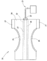
図7は、従来の水分センサーの具体的構造を模式的に示す図である。図8は、この水分センサーの断面構造を模式的に示す図である。 FIG. 7 is a diagram schematically showing a specific structure of a conventional moisture sensor. FIG. 8 is a diagram schematically showing a cross-sectional structure of the moisture sensor.
上記水分センサー2は、6層構造を備えている。水分センサー2は、防水フィルム7、和紙8、電極9、10及び和紙11を備えている。この電極9、10は、帯状に裁断されたアルミ箔からなる。防水フィルム7は、ノリ(化学ノリ)12を介して和紙8の下面に接着されている。また、和紙8の上面に電極9、10が接着されている。接着剤としてパラフィン(不図示)が採用される。和紙8と和紙11との間に導電性接着剤13が介在されており、この導電性接着剤13に電極9、10が埋設されている。この導電性接着剤13は、本願出願人が保有する特許権に係る特許公報(特許第3274130号公報)に開示されており、乾燥状態では絶縁性を示し、水分を吸収したときに導電性を示すものである。
The
たとえば和紙11上に排尿された場合は、尿の水分が和紙11を通過して導電性接着剤13に至る。これにより、当該導電性接着剤13が導電性を示し、電極9及び電極10間が導通され、水分センサー2が排尿を検知する。
For example, when urination is performed on the
上記電極9、10は、シート状に形成されたアルミ箔が前述のように帯状に裁断されることにより構成される。ただし、このような工程で電極9、10が形成されるためには、生産技術上、アルミ箔の周面(表裏面)に所要の防錆処理が必要となる。アルミ箔周面が剥出状態であれば、原料としてのシート状アルミ箔が腐食するおそれがあるからである。
The
ところが、このような防錆処理が施されることにより良好な導電性を示す部分は裁断面のみとなり、電極9、10の導電性が阻害されることは否めない。しかも、製造工程が複雑になり、水分センサー2の製造コストが上昇する。さらに、前述のように、電極9、10はパラフィンを介して和紙8に接着されているが、このパラフィンは疎水性を示すことから、電極9、10が撥水性を帯びてしまう。そして、このような事情から、水分センサー2が設計上の感度を発揮することができないという問題があった。
However, when such a rust prevention treatment is performed, the portion showing good conductivity is only a cut surface, and it cannot be denied that the conductivity of the
かかる問題を解決するために、本願出願人は、上記特許文献2に係る水分センサーを発明し、特許出願した。この水分センサーでは、水分の存在を検知するための一対の電極が水溶性の導電性インク(水性カーボンインク)からなり、当該インクを用いて電極がシートに印刷されている。これにより、水分の検知感度が向上している。
In order to solve such a problem, the present applicant invented the moisture sensor according to
しかしながら、上記水性カーボンインク等により電極が構成された場合には、当該電極の耐久性が低下してしまう。すなわち、大量の水分が電極の周辺に存在する場合には、当該電極が溶融するおそれがある。電極が溶融すれば、検知感度が著しく低下するばかりか、検知不能となる場合も考えられる。 However, when the electrode is composed of the water-based carbon ink or the like, the durability of the electrode is lowered. That is, when a large amount of moisture exists around the electrode, the electrode may be melted. If the electrode is melted, not only the detection sensitivity is remarkably lowered but also the detection is impossible.
本発明は、かかる背景のもとになされたものであって、その目的は、高いセンシング精度を発揮すると共に耐久性優れ、しかも安価な成人用オムツや人工透析用シートに採用される水分センサを提供することである。 The present invention has been made based on such a background, and an object of the present invention is to provide a moisture sensor that is used in an adult diaper or an artificial dialysis sheet that exhibits high sensing accuracy and excellent durability. Is to provide.
(1) 本発明に係る水分センサーは、吸水性を有する第1シートと、第1シートの上面に所定距離を隔てて並設された一対の帯状電極と、導電性を有しない接着剤を介して上記一対の帯状電極を挟み込むように第1シートの上面に接着された第2シートとを備え、上記一対の帯状電極は、上記第1シート上に塗布された導電性を有する糊からなる。 (1) The moisture sensor according to the present invention includes a first sheet having water absorption, a pair of strip electrodes arranged in parallel on the upper surface of the first sheet at a predetermined distance, and a non- conductive adhesive. And a second sheet bonded to the upper surface of the first sheet so as to sandwich the pair of band-shaped electrodes, and the pair of band-shaped electrodes are made of conductive glue applied on the first sheet.
上記帯状電極は、導電性をする糊からなるので、当該帯状電極は、耐腐食性に優れる。このため、一対の帯状電極は、特に表面防錆処理等が施されることなく剥き出し状態で第1シートの上面に配置され得る。したがって、各帯状電極の導電性が妨げられることがない。また、上記帯状電極が上記導電性を有する糊からなるので、大量の水分が存在する環境においても、当該帯状電極が容易に溶融することがなく、水分のセンシング機能が著しく低下することがない。 Since the strip electrode is made of conductive glue, the strip electrode is excellent in corrosion resistance. For this reason, a pair of strip electrode can be arrange | positioned on the upper surface of a 1st sheet | seat in the bare state, without performing surface rust prevention process etc. especially. Therefore, the conductivity of each strip electrode is not hindered. In addition, since the strip electrode is made of the conductive paste, the strip electrode is not easily melted even in an environment where a large amount of moisture exists, and the moisture sensing function is not significantly lowered.
(2) 上記導電性を有する糊は、馬鈴薯1質量%以上5質量%以下及び水が74質量%以上84質量%以下を含む水溶性の糊に親水性カーボンブラックが混練されたものであるのが好ましい。 (2) The conductive paste is obtained by kneading hydrophilic carbon black in water-soluble paste containing 1% by mass to 5% by mass of potato and 74% by mass to 84% by mass of water. Is preferred.
この構成では、いわゆる天然素材によって上記帯状電極が形成されるので、使用者の身体に害を与えることがない。しかも、上記帯状電極が安価に製造される。 In this structure, since the said strip | belt-shaped electrode is formed with what is called a natural material, it does not harm a user's body. Moreover, the strip electrode is manufactured at a low cost.
(3) 上記一対の帯状電極は、上記導電性を有する糊をインクとするグラビア印刷により形成されるのが好ましい。 (3) The pair of strip electrodes are preferably formed by gravure printing using the conductive paste as ink.
この構成では、一対の帯状電極が簡単に且つ一層安価に形成される。 In this configuration, the pair of strip electrodes can be formed easily and at a lower cost.
(4) 上記第1シートの下面に撥水性シートが重ね合わされているのが好ましい。さらに、当該撥水性シートの上記帯状電極に対応する位置に、蛍光塗料が付されていてもよい。 (4) It is preferable that a water repellent sheet is superimposed on the lower surface of the first sheet. Furthermore, a fluorescent paint may be attached to a position corresponding to the strip electrode of the water repellent sheet.
この構成では、撥水性シートが設けられているので、水分が第1シートを通過することがない。このため、たとえば当該水分センサーが成人用オムツや人工透析用シートに採用された場合に、着用者の衣類やシーツが汚れることが防止される。また、成人用オムツや人工透析用シートは定期的に交換されるものであるが、これらの交換時には上記帯状電極に対してコネクタが着脱される。この作業は夜間に行われることもあり、その場合、介護者は、帯状電極の位置が確認しずらい。しかし、この構成では、上記帯状電極に対応する位置に蛍光塗料が付されているので、介護者は帯状電極の位置が確認しやすく、成人用オムツや人工透析用シートの交換作用が容易である。 In this configuration, since the water repellent sheet is provided, moisture does not pass through the first sheet. For this reason, when the said moisture sensor is employ | adopted for the diaper for adults or the sheet | seat for artificial dialysis, for example, it is prevented that a wearer's clothing and sheets become dirty. In addition, adult diapers and artificial dialysis sheets are regularly replaced. At the time of replacement, the connector is attached to and detached from the strip electrode. This operation may be performed at night, in which case it is difficult for the caregiver to confirm the position of the strip electrode. However, in this configuration, since the fluorescent paint is applied to the position corresponding to the strip electrode, the caregiver can easily confirm the position of the strip electrode, and the exchange operation of the adult diaper and the artificial dialysis sheet is easy. .
本発明によれば、耐腐食性及び耐久性(耐水性)に優れた導電性の糊により帯状電極が形成されているので、当該帯状電極に表面防錆処理等が施される必要はない。したがって、当該帯状電極の導電性が妨げられることがなく、高いセンシング精度が維持される。 According to the present invention, since the strip electrode is formed of the conductive paste having excellent corrosion resistance and durability (water resistance), the strip electrode need not be subjected to surface rust prevention treatment or the like. Therefore, the conductivity of the strip electrode is not hindered and high sensing accuracy is maintained.
以下、適宜図面が参照されつつ、好ましい実施形態に基づいて本発明が詳細に説明される。 Hereinafter, the present invention will be described in detail based on preferred embodiments with appropriate reference to the drawings.
[概略構成] [Schematic configuration]
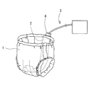
図1が示すように、この成人用オムツ20は、たとえば介護が必要な痴呆症状が現れた成人によって使用される。この成人用オムツ20は、本発明の一実施形態に係る水分センサー22を備えている。介護者は、成人用オムツ20を定期的に取り替えるが、オムツ取替作業は、排尿等の後に直ちに行われるべきである。排尿等の時期は、従来から排尿報知装置21によって介護者に知らされるようになっている。排尿報知装置21は、排尿等の時期をブザー等で報知するが、排尿等の有無は、上記水分センサー22によって検知される。また、排尿放置装置21はコネクタ23を備えており、当該コネクタ23を介して水分センサー22と排尿報知装置21とが接続されている。
As FIG. 1 shows, this
[オムツ本体] [Diaper body]
成人用オムツ20は、オムツ本体24を備えている。オムツ本体24は、既知の構造である。オムツ本体24は、たとえば所定のポリマーからなる不織布等で構成されており、十分な容量の水分吸収材が内臓されている。図2が示すように、オムツ本体24の両側部分25は円弧状に切り欠かれており、端部に固定用テープ27が設けられている。使用者は、オムツ本体24を陰部にあてがって固定用テープ27により固定する。これにより、成人用オムツ20は、レッグホール26(図1参照)が形成された下着形状となり、使用者は、優れた装着感が得られるようになっている。
The
[水分センサ] [Moisture sensor]
水分センサー22は、オムツ本体24を構成する不織布の内側に設けられている。水分センサー22は、短冊状に形成されており、図2が示すように、オムツ本体24の長手方向に沿って配置されている。したがって、図1が示すように、使用者が成人用オムツ20を着用したときは、水分センサー22は、股部を覆うように配置される。
The
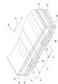
図3が示すように、水分センサー22は、5層構造を有する。すなわち、水分センサー22は、メインシート31(本発明における「第1シート」の一例)と、このメインシート31の内側に配置されたサブシート32(本発明における「第2シート」の一例)と、このメインシート31の外側に配置された防水シート33(本発明における「撥水シート」の一例)とを有する。そして、メインシート31とサブシート32との間に接着剤34が介在されると共に、メインンシート31と防水シート33との間にも接着剤35が介在されている。これら接着剤34、35は、接着剤層を形成している。上記メインシート31は、一対の電極36、37(本発明における「帯状電極」の一例)を備えている。上記サブシート32は、成人用オムツ20の内壁面を構成する不織布の直下に配置されており、もし、尿等の水分が当該不織布に付着したならば、当該水分は当該不織布を通過して上記サブシート32に到達する。
As shown in FIG. 3, the
メインシート31は、細長帯状に形成されており、本実施形態では和紙からなる。メインシート31を構成する材料は、和紙に限定される必要はない。要するに、吸水性に富むものでありながら水に溶けにくく、乾燥状態において電気絶縁性を有するものであれば、紙のほか布等もメインシート31の材料として採用され得る。また、メインシート31の厚さは、0.3mm〜0.8mm程度に設定される。
The
電極36、37は、導電性を有するインクによって構成されている。すなわち、本実施形態では、このインクは、水溶性の糊に親水性カーボンブラックが混練されたものである。この水溶性の糊は、本実施形態では、たとえば馬鈴薯1質量%以上5質量%以下で含み、及び水が74質量%以上84質量%以下で含む糊が採用され得る。この水溶性の糊は、水及び馬鈴薯澱粉が混合され、加熱しながら撹拌されることによって生成される。そして、この撹拌生成物が均一な粘稠性を呈すれば、これが冷却されることにより、水溶性の糊が製造される。
The
もっとも、上記水溶性の糊に食塩が混練されていてもよい。つまり、上記インクに導電性の糊が採用されていてもよい。具体的には、たとえば馬鈴薯1質量%以上5質量%以下、食塩15質量%以上21質量%以下及び水が74質量%以上84質量%以下からなる糊が採用され得る。混練される食塩の量は、常温で水に溶解し得る飽和溶解度付近の量でもよい。この導電性の糊は、水、食塩及び馬鈴薯澱粉が混合され、加熱しながら撹拌されることによって生成される。そして、この撹拌生成物が均一な粘稠性を呈すれば、これが冷却されることにより、導電性を備えた糊が製造される。 But salt may be knead | mixed with the said water-soluble paste. That is, conductive glue may be used for the ink. Specifically, for example, a paste composed of 1% by mass to 5% by mass of potato, 15% by mass to 21% by mass of sodium chloride, and 74% by mass to 84% by mass of water can be employed. The amount of salt to be kneaded may be an amount in the vicinity of saturation solubility that can be dissolved in water at room temperature. This conductive paste is produced by mixing water, salt and potato starch and stirring with heating. And if this stirring product exhibits uniform viscosity, the paste with electroconductivity will be manufactured by cooling this.
電極36、37は、メインシート31の上面38に印刷されている。この場合、上記水溶性の糊に親水性カーボンブラックが混練されたものが、インクとして使用される。前述のように、この水溶性の糊が導電性を備えていてもよい。両電極36、37は、メインシート31の長手方向(すなわち水分センサー22の長手方向)に直交する方向(図3において矢印39の方向)に沿って所定距離だけ隔てて配置されている。両者間の隙間sは、5mm〜25mm程度に設定され得る。各電極36、37の幅wは、2mm〜25mm程度に設定される。本実施形態では、各電極36、37は、上記インクを用いたグラビア印刷により構成される。したがって、各電極36、37の厚さ寸法は、きわめて小さく設定され、その結果、メインシート31の柔軟性が損なわれることがない。
The
なお、上記グラビア印刷に代えて、上記インクを用いたシルク印刷により電極36、37が構成されてもよい。また、上記親水性カーボンブラックに代えて、アルミニウム合金の粉末その他の金属粉のほか、電極36、37の導電率を向上させる材料が採用されてもよい。本実施形態のように、親水性カーボンブラックが採用されることにより、当該成人用オムツ20を廃棄する場合、水分センサー22部分(具体的には、電極36、37部分)を分別廃棄する必要がなく、一般のゴミとして処理できるという利点もある。
Note that the
サブシート32は、メインシート31と同様の細長帯状に形成されており、メインシート31の上面38を完全に覆っている。本実施形態では、サブシート32も和紙からなり、その厚さは、0.3mm〜0.8mm程度に設定される。サブシート32を構成する材料も和紙に限定されず、要するに、吸水性に富み、水に溶けにくく、乾燥状態において電気絶縁性を有するものであればよい。
The sub-sheet 32 is formed in an elongated strip shape similar to the
接着剤34は、本実施形態では、食塩が混練された水溶性接着剤が採用されている。すなわち、接着剤34は、導電性を有する。なお、サブシート32がメインシート31に接着される前に予めサブシート32に食塩水が吸収され、乾燥されてもよい。これにより、一対の電極36、37は、メインシート31及びサブシート32によって挟み込まれ、乾燥時に電気的に絶縁され、接着剤34又はサブシート32が吸水した状態で導通される。
In this embodiment, the adhesive 34 is a water-soluble adhesive in which salt is kneaded. That is, the adhesive 34 has conductivity. In addition, before the sub sheet |
接着剤34として、具体的には、上記導電性を有するインクに使用された糊と同様に、たとえば馬鈴薯1質量%以上5質量%以下、食塩15質量%以上21質量%以下及び水が74質量%以上84質量%以下からなる糊が採用され得る。この食塩の量は、常温で水に溶解し得る飽和溶解度付近の量でもよい。この糊は、水、食塩及び馬鈴薯澱粉が混合され、加熱しながら撹拌されることによって生成される。そして、この撹拌生成物が均一な粘稠性を呈すれば、これが冷却されることにより、導電性を備えた糊が製造される。もっとも、本実施形態では、接着剤34が導電性を備えているが、上記食塩を含まず導電性を有しない糊が接着剤34として採用されてもよい。 Specifically, as the adhesive 34, for example, 1% by mass to 5% by mass of potato, 15% by mass to 21% by mass of sodium chloride, and 74% by mass of water are used in the same manner as the paste used in the conductive ink. % Or more and 84% by mass or less can be used. The amount of the salt may be an amount in the vicinity of the saturation solubility that can be dissolved in water at room temperature. This glue is produced by mixing water, salt and potato starch and stirring with heating. And if this stirring product exhibits uniform viscosity, the paste with electroconductivity will be manufactured by cooling this. However, in the present embodiment, the adhesive 34 has conductivity, but a paste that does not contain the above-described salt and does not have conductivity may be employed as the adhesive 34.
防水シート33は、メインシート31と同様の細長帯状に形成されており、メインシート31の下面を完全に覆っている。防水シート33は、たとえば、ポリエチレンテレフタレートフィルムからなる。このポリエチレンテレフタレートフィルムは柔軟性に富むので、水分センサー20の柔軟性が損なわれることがない。防水シート33を構成する材料は、ポリエチレンテレフタレートフィルムに限定されるものではなく、エチレン酢酸ビニル共重合体フィルム、ポリテトラフルオロエチレンフィルム等も採用され得る。なお、この防水シート33は、省略されてもよい。
The waterproof sheet 33 is formed in an elongated strip shape similar to the
接着剤35は、防水シート33をメインシート31に接着する。接着剤35としては、ウレタン糊その他の汎用の工業用糊が採用され得る。
The adhesive 35 adheres the waterproof sheet 33 to the
[作用・効果] [Action / Effect]
使用者が成人用オムツ20を着用した状態でたとえば排尿した場合、水分センサー22が排尿を検知し、排尿放置装置21によって排尿が介護者等に報知される。水分センサー22の電極36、37が前述の導電性を有する糊から構成されているので、電極36、37は耐腐食性に優れる。このため、従来のように、各電極36、37の表面に防錆処理等が施される必要はなく、各電極36、37は、メインシート31上に剥き出し状態で配置されている。すなわち、各電極36、37の導電性が妨げられることはない。したがって、上記排尿があったときは、メインシート31に付着した水分が接着剤34に達し、当該接着剤34が導電性を発揮すると共に、直ちに電極36、37間が導通することになる。その結果、排尿が迅速且つ確実に検知される。
For example, when the user urinates while wearing the
特に本実施形態では、電極36、37が上記糊からなるので、たとえば大量の尿が排出されたとしても、電極が水分によって容易に溶融することがない。したがって、水分センサー22のセンシング機能が害されることはなく、耐久性(耐水性)が向上する。なお、オムツ本体24を構成する材料に所定の導通性を有するポリマー等が採用された場合には、上記接着剤34は導電性を備える必要はなく、排尿時に上記オムツ本体24が電極36、37間を導通させる。
In particular, in the present embodiment, since the
また、本実施形態では、一対の電極36、37は、前述のように上記導電性を備えた糊をインクとしたグラビア印刷により形成される。したがって、電極36、37が簡単に且つ安価に形成されるという利点がある。なお、電極36、37は、グラビア印刷に代えてシルク印刷によっても形成され得る。
In the present embodiment, the pair of
さらに、本実施形態では、メインシート31の下面に防水シート33が重ね合わされているので、水分がメインシート31を通過することがない。このため、排尿等があったときでも、使用者の衣服が汚れることはない。
Furthermore, in the present embodiment, since the waterproof sheet 33 is superimposed on the lower surface of the
[変形例] [Modification]
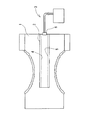
図4が示すように、この変形例に係る水分センサー42が上記実施形態に係る水分センサー22と異なるところは、防水シート33の下面43に蛍光塗料44、45が塗布されている点である。この蛍光塗料44、45は、防水シート33の下面43に印刷される。蛍光塗料44は、細長帯状に塗布されており、電極36に対向するように配置されている。同様に、蛍光塗料45も細長帯状に塗布されており、電極37に対向するように配置されている。
As shown in FIG. 4, the
成人用オムツ20は、定期的に交換されるものである。この交換時には、上記電極36、37に対してコネクタ23が着脱される。ところで、成人用オムツ20の交換作業は夜間に行われることもあり、その場合、介護者は、電極36、37の位置が確認しずらいという問題がある。しかし、本変形例では、上記電極36、37に対応する位置に上記蛍光塗料が帯状に塗布されているので、介護者は電極36、37の位置が確認しやすく、当該交換作用が容易になるという利点がある。
The
また、本実施形態では、水分センサー22、42は、成人用オムツに適用されているが、水分センサー22、42は、人工透析用シート等に搭載されてもよいことは勿論である。ただし、この場合、上記接着剤34は、導電性を備えていることが好ましい。
In the present embodiment, the
22・・・水分センサー
31・・・メインシート
32・・・サブシート
33・・・防水シート
34・・・接着剤
35・・・接着剤
36・・・電極
37・・・電極
38・・・上面
42・・・水分センサー
43・・・下面
44・・・蛍光塗料
45・・・蛍光塗料
22 ...
Claims (4)
第1シートの上面に所定距離を隔てて並設された一対の帯状電極と、
導電性を有しない接着剤を介して上記一対の帯状電極を挟み込むように第1シートの上面に接着された第2シートとを備え、
上記一対の帯状電極は、上記第1シート上に塗布された導電性を有する糊からなる水分センサー。 A first sheet having water absorption;
A pair of strip electrodes arranged in parallel on the upper surface of the first sheet at a predetermined distance;
A second sheet adhered to the upper surface of the first sheet so as to sandwich the pair of strip electrodes via an adhesive having no conductivity ,
The pair of strip electrodes are moisture sensors made of conductive glue applied on the first sheet.
The moisture sensor according to any one of claims 1 to 3, wherein a water repellent sheet is superimposed on a lower surface of the first sheet, and a fluorescent paint is applied to a position corresponding to the strip electrode of the water repellent sheet. .
Priority Applications (1)
| Application Number | Priority Date | Filing Date | Title |
|---|---|---|---|
| JP2011093926A JP5773723B2 (en) | 2011-04-20 | 2011-04-20 | Moisture sensor |
Applications Claiming Priority (1)
| Application Number | Priority Date | Filing Date | Title |
|---|---|---|---|
| JP2011093926A JP5773723B2 (en) | 2011-04-20 | 2011-04-20 | Moisture sensor |
Publications (2)
| Publication Number | Publication Date |
|---|---|
| JP2012223386A JP2012223386A (en) | 2012-11-15 |
| JP5773723B2 true JP5773723B2 (en) | 2015-09-02 |
Family
ID=47274267
Family Applications (1)
| Application Number | Title | Priority Date | Filing Date |
|---|---|---|---|
| JP2011093926A Active JP5773723B2 (en) | 2011-04-20 | 2011-04-20 | Moisture sensor |
Country Status (1)
| Country | Link |
|---|---|
| JP (1) | JP5773723B2 (en) |
Families Citing this family (7)
| Publication number | Priority date | Publication date | Assignee | Title |
|---|---|---|---|---|
| JP5770148B2 (en) * | 2012-10-30 | 2015-08-26 | ミサワホーム株式会社 | Built-in moisture meter |
| JP6301773B2 (en) * | 2014-07-31 | 2018-03-28 | 花王株式会社 | Wearing article |
| KR102068269B1 (en) * | 2018-02-28 | 2020-02-11 | (주)크레이더스 | Absorbent article |
| KR102121923B1 (en) * | 2018-02-28 | 2020-06-11 | (주)크레이더스 | Method for fabricating absorbent article and pattern roll |
| EP3636234A4 (en) * | 2017-06-05 | 2021-01-20 | Craders Co.,Ltd | Method for manufacturing absorption product |
| JP6486521B2 (en) * | 2018-02-28 | 2019-03-20 | 花王株式会社 | Wearing article |
| JP2021171571A (en) | 2020-04-30 | 2021-11-01 | ユニ・チャーム株式会社 | Absorbent article and defecation or urination determination method |
Family Cites Families (8)
| Publication number | Priority date | Publication date | Assignee | Title |
|---|---|---|---|---|
| JPH05190015A (en) * | 1992-01-09 | 1993-07-30 | Toshiba Chem Corp | Water soluble conductive paste |
| JP3220229B2 (en) * | 1992-05-26 | 2001-10-22 | テルモ株式会社 | Heating element for tube connection device and method of manufacturing the same |
| JP2000093448A (en) * | 1998-09-18 | 2000-04-04 | Panetto:Kk | Sensor for diaper and diaper containing the same |
| JP3274130B2 (en) * | 2000-05-29 | 2002-04-15 | 滿 藤原 | Urine detection switch and urine detection device |
| US20040186467A1 (en) * | 2003-03-21 | 2004-09-23 | Swanson David K. | Apparatus for maintaining contact between diagnostic and therapeutic elements and tissue and systems including the same |
| JP2007151624A (en) * | 2005-11-30 | 2007-06-21 | Awajitec:Kk | Moisture sensor |
| US20080054408A1 (en) * | 2006-08-31 | 2008-03-06 | Kimberly-Clark Worldwide, Inc. | Conduction through a flexible substrate in an article |
| JP2011075347A (en) * | 2009-09-30 | 2011-04-14 | Awajitec:Kk | Moisture sensor |
-
2011
- 2011-04-20 JP JP2011093926A patent/JP5773723B2/en active Active
Also Published As
| Publication number | Publication date |
|---|---|
| JP2012223386A (en) | 2012-11-15 |
Similar Documents
| Publication | Publication Date | Title |
|---|---|---|
| JP5773723B2 (en) | Moisture sensor | |
| JP2011075347A (en) | Moisture sensor | |
| AU2010309091B2 (en) | Defecation/urination determination apparatus | |
| KR101273195B1 (en) | urine sensor | |
| JP5396234B2 (en) | Defecation detection device | |
| JP5396232B2 (en) | Defecation detection device | |
| US8546639B2 (en) | Urine suction device | |
| JP6232216B2 (en) | Absorbent articles | |
| JP6275473B2 (en) | Wearing article | |
| US10928344B2 (en) | Slotted sensor for detection of moisture in a diaper | |
| JP2009006180A (en) | Urine sensor | |
| EP3143975B1 (en) | Smart nursing consumable, rollable sensor module thereof and manufacturing method thereof | |
| JP2019187741A (en) | Absorbent article with sensor and production method thereof | |
| JP2017020817A (en) | Liquid detection sensor | |
| KR20110113008A (en) | Excrements detector for diaper | |
| WO2021085151A1 (en) | Absorbent article and excretion detection device having same | |
| CN115297814B (en) | Absorbent article and method for determining urination and defecation | |
| JP5129073B2 (en) | Urine receiver | |
| JPH07159362A (en) | Sensor for detecting diaper change timing |
Legal Events
| Date | Code | Title | Description |
|---|---|---|---|
| A621 | Written request for application examination |
Free format text: JAPANESE INTERMEDIATE CODE: A621 Effective date: 20131218 |
|
| A977 | Report on retrieval |
Free format text: JAPANESE INTERMEDIATE CODE: A971007 Effective date: 20140926 |
|
| A131 | Notification of reasons for refusal |
Free format text: JAPANESE INTERMEDIATE CODE: A131 Effective date: 20140930 |
|
| A521 | Request for written amendment filed |
Free format text: JAPANESE INTERMEDIATE CODE: A523 Effective date: 20141127 |
|
| TRDD | Decision of grant or rejection written | ||
| A01 | Written decision to grant a patent or to grant a registration (utility model) |
Free format text: JAPANESE INTERMEDIATE CODE: A01 Effective date: 20150623 |
|
| A61 | First payment of annual fees (during grant procedure) |
Free format text: JAPANESE INTERMEDIATE CODE: A61 Effective date: 20150630 |
|
| R150 | Certificate of patent or registration of utility model |
Ref document number: 5773723 Country of ref document: JP Free format text: JAPANESE INTERMEDIATE CODE: R150 |
|
| R250 | Receipt of annual fees |
Free format text: JAPANESE INTERMEDIATE CODE: R250 |
|
| R250 | Receipt of annual fees |
Free format text: JAPANESE INTERMEDIATE CODE: R250 |
|
| R250 | Receipt of annual fees |
Free format text: JAPANESE INTERMEDIATE CODE: R250 |
|
| R250 | Receipt of annual fees |
Free format text: JAPANESE INTERMEDIATE CODE: R250 |
|
| R250 | Receipt of annual fees |
Free format text: JAPANESE INTERMEDIATE CODE: R250 |
|
| R250 | Receipt of annual fees |
Free format text: JAPANESE INTERMEDIATE CODE: R250 |
|
| S531 | Written request for registration of change of domicile |
Free format text: JAPANESE INTERMEDIATE CODE: R313531 |
|
| R350 | Written notification of registration of transfer |
Free format text: JAPANESE INTERMEDIATE CODE: R350 |