JP5773657B2 - Method of grounding solar energy utilization device and pedestal beam member used therefor - Google Patents
Method of grounding solar energy utilization device and pedestal beam member used therefor Download PDFInfo
- Publication number
- JP5773657B2 JP5773657B2 JP2011007468A JP2011007468A JP5773657B2 JP 5773657 B2 JP5773657 B2 JP 5773657B2 JP 2011007468 A JP2011007468 A JP 2011007468A JP 2011007468 A JP2011007468 A JP 2011007468A JP 5773657 B2 JP5773657 B2 JP 5773657B2
- Authority
- JP
- Japan
- Prior art keywords
- solar cell
- energy utilization
- solar energy
- beam member
- ground
- Prior art date
- Legal status (The legal status is an assumption and is not a legal conclusion. Google has not performed a legal analysis and makes no representation as to the accuracy of the status listed.)
- Active
Links
Images


Classifications
-
- Y—GENERAL TAGGING OF NEW TECHNOLOGICAL DEVELOPMENTS; GENERAL TAGGING OF CROSS-SECTIONAL TECHNOLOGIES SPANNING OVER SEVERAL SECTIONS OF THE IPC; TECHNICAL SUBJECTS COVERED BY FORMER USPC CROSS-REFERENCE ART COLLECTIONS [XRACs] AND DIGESTS
- Y02—TECHNOLOGIES OR APPLICATIONS FOR MITIGATION OR ADAPTATION AGAINST CLIMATE CHANGE
- Y02B—CLIMATE CHANGE MITIGATION TECHNOLOGIES RELATED TO BUILDINGS, e.g. HOUSING, HOUSE APPLIANCES OR RELATED END-USER APPLICATIONS
- Y02B10/00—Integration of renewable energy sources in buildings
- Y02B10/10—Photovoltaic [PV]
-
- Y—GENERAL TAGGING OF NEW TECHNOLOGICAL DEVELOPMENTS; GENERAL TAGGING OF CROSS-SECTIONAL TECHNOLOGIES SPANNING OVER SEVERAL SECTIONS OF THE IPC; TECHNICAL SUBJECTS COVERED BY FORMER USPC CROSS-REFERENCE ART COLLECTIONS [XRACs] AND DIGESTS
- Y02—TECHNOLOGIES OR APPLICATIONS FOR MITIGATION OR ADAPTATION AGAINST CLIMATE CHANGE
- Y02E—REDUCTION OF GREENHOUSE GAS [GHG] EMISSIONS, RELATED TO ENERGY GENERATION, TRANSMISSION OR DISTRIBUTION
- Y02E10/00—Energy generation through renewable energy sources
- Y02E10/50—Photovoltaic [PV] energy
Description
本発明は、建物の屋根などに設置される太陽電池パネルなどの太陽エネルギー利用装置に関するものであり、より詳しくは、帯電した電荷をアース(接地)するための技術に関するものである。 The present invention relates to a solar energy utilization device such as a solar battery panel installed on the roof of a building, and more particularly to a technique for grounding a charged charge.
従来、建物の屋根などに設置される太陽電池パネルなどの太陽エネルギー利用装置においては、装置に帯電した電荷をアース(接地)する必要があり、アースケーブルを用いたアース接続が行われている。そして、このことに関連する技術について開示する文献も存在する(例えば、特許文献1参照。)。 2. Description of the Related Art Conventionally, in a solar energy utilization device such as a solar cell panel installed on a roof of a building, it is necessary to ground (ground) an electric charge charged in the device, and ground connection using a ground cable is performed. There is also a document that discloses a technique related to this (see, for example, Patent Document 1).
特許文献1に開示される技術では、従来は、隣り合う太陽電池パネル同士をアースケーブルで接続していたところ、導電性を有する保護板を用いることによって、太陽電池パネル同士を接続するためのアースケーブルを不要とする技術について開示している。 In the technology disclosed in Patent Document 1, conventionally, adjacent solar cell panels are connected to each other with a ground cable. However, by using a protective plate having conductivity, grounding for connecting the solar cell panels to each other is performed. A technology that eliminates the need for cables is disclosed.
また、特許文献2に開示されるように、桟部材の上に太陽電池パネルが設置される構造も知られており、このような構造の場合においては、特許文献1で指摘されているように、各太陽電池パネルをアースケーブルで接続する形態が採用されていた。この特許文献2では、アース接続に関する手間を削減するために、縦桟部材に対してスライドさせる固定部材にアース部材を取付ける構成について開示している。
Further, as disclosed in
しかし、特許文献1に開示されるような保護板を用いる形態では、保護板を別途製作、設置する必要があり、コストの問題や施工性において課題が残るものであると考えられる。また、太陽電池パネルのフレームに穴加工が必要となるため、専用の設計が要求されることや、現場加工なども要求されることが懸念される。例えば、汎用性のある太陽電池パネルにおいては、技術を適用できない、といったことも懸念される。 However, in the form using the protective plate as disclosed in Patent Document 1, it is necessary to separately manufacture and install the protective plate, and it is considered that problems remain in terms of cost and workability. Moreover, since hole processing is required for the frame of the solar cell panel, there is a concern that a dedicated design is required and that on-site processing is also required. For example, there is a concern that the technology cannot be applied to a versatile solar cell panel.
また、特許文献1における図の4に開示されるように、各列同士ではアースケーブルを用いて電気的な接続を行うことを前提としており、アースケーブルの配線手間の削減について、課題が残るものであった。 In addition, as disclosed in FIG. 4 in Patent Document 1, it is assumed that each column is electrically connected using a ground cable, and there remains a problem with respect to the reduction of the wiring effort of the ground cable. Met.
また、特許文献2に開示される構成の場合では、多くのワッシャーやボルトなどを用いて固定部材とアース部材を一体化させることから、組立ての手間がかかるものである。また、施工時において、太陽電池パネルの大きさに合わせてスライドさせ、細かな位置調整が必要になり、また、締結の作業が必要となるなど、施工手間がかかるものである。
Moreover, in the case of the structure disclosed by
特に、屋根の上という高所の作業環境において細かな手作業をする際には、部品を落下させないように注意を払うなど、より慎重になる必要があり、作業者に大きな負担を強いるとともに、作業時間も多く要してしまうことになる。また、作業者による施工のばらつきが生じることも懸念され、アース接続が確実に実現されないといったことも懸念される。 In particular, when carrying out fine manual work in a high working environment on the roof, it is necessary to be more careful, such as paying attention not to drop parts, and it imposes a heavy burden on the operator, It takes a lot of work time. In addition, there is a concern that variations in construction by the operator may occur, and there is a concern that the ground connection cannot be reliably realized.
そこで、本発明は以上の問題に鑑み、建物の屋根に設置される太陽電池パネルなどの太陽エネルギー利用装置について、各装置間におけるアースケーブルの接続を不要とするための新規な技術について提案するものである。 Accordingly, in view of the above problems, the present invention proposes a novel technique for eliminating the need for connection of a ground cable between devices for solar energy utilization devices such as solar battery panels installed on the roof of a building. It is.
本発明の解決しようとする課題は以上の如くであり、次にこの課題を解決するための手段を説明する。 The problem to be solved by the present invention is as described above. Next, means for solving the problem will be described.
即ち、請求項1に記載のごとく、太陽エネルギー利用装置の接地方法であって、前記太陽エネルギー利用装置を設置する架台を構成する架台用桟部材には、架台用桟部材の両側にそれぞれ前記太陽エネルギー利用装置が載置される対向部が設けられ、前記各対向部には、それぞれアース部材が締結具にて予め固定されており、前記架台用桟部材の一方の対向部に一方の前記太陽エネルギー利用装置を載置することで、一方の前記アース部材を介して前記太陽エネルギー利用装置の下部と前記架台用桟部材が電気的に導通され、前記架台用桟部材の他方の対向部に他方の前記太陽エネルギー利用装置を載置することで、他方の前記アース部材を介して前記太陽エネルギー利用装置の下部と前記架台用桟部材が電気的に導通される、太陽エネルギー利用装置の接地方法とする。 That is, as described in claim 1, in the grounding method of the solar energy utilization device, the frame member for the frame that constitutes the frame on which the solar energy utilization device is installed is provided on each side of the beam member for the frame. energy utilization device facing portion is provided to be placed, wherein the respective facing portions, the grounding member respectively are pre-fixed by a fastener, one of the sun on one of the opposing portions of the mounting member crosspiece member By placing the energy utilization device, the lower part of the solar energy utilization device and the pedestal beam member are electrically connected to each other through the one earth member, and the other opposite part of the gantry beam member by placing the other of the solar energy utilization system, the lower and the mounting member crosspiece member of the solar energy utilization device is electrically connected via the other of said grounding member, solar energy The grounding method of using device.
また、請求項2に記載のごとく、請求項1に記載の太陽エネルギー利用装置の接地方法に用いる架台用桟部材とする。
Further, as described in
本発明の効果として、以下に示すような効果を奏する。 As effects of the present invention, the following effects can be obtained.
即ち、請求項1に記載の発明においては、
架台用桟部材に太陽エネルギー利用装置を設置するだけで、両者間の電気的な導通をアースケーブルを用いずに実現することが可能となる。また、作業者による施工のばらつきの発生が抑制されるとともに、アース接続に関する作業を短時間で実施することができるため、施工性に優れた構造が実現できる。
That is, in the invention according to claim 1,
It is possible to achieve electrical continuity between the two without using a ground cable simply by installing a solar energy utilization device on the frame member for the gantry. In addition, the occurrence of variations in construction by the operator is suppressed, and work related to ground connection can be performed in a short time, so that a structure with excellent workability can be realized.
また、請求項2に記載の発明においては、
前記各ユニット間の電気的な導通をアースケーブルを用いずに実現することが可能となる。また、作業者による施工のばらつきの発生が抑制されるとともに、アース接続に関する作業を短時間で実施することができるため、施工性に優れた構造が実現できる。
In the invention according to
It is possible to realize electrical continuity between the units without using a ground cable. In addition, the occurrence of variations in construction by the operator is suppressed, and work related to ground connection can be performed in a short time, so that a structure with excellent workability can be realized.
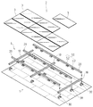
図1は、本発明の一実施形態の全体概要を示すものである。
図1に示すごとく、本発明は、屋根1の上に太陽エネルギー利用装置2が設置されるものなどについて適用されるものであり、実施形態として、複数の太陽電池パネル3・3・・・が配置されるものとしている。
また、屋根1に向かって奥行き方向を長手方向として配置される縦桟部材10や、屋根1に向かって横方向を長手方向として配置される横桟部材20などから架台4が構成され、この架台4に対し太陽電池パネル3・3・・・が載置固定されるものとしている。
なお、屋根の上に設置される太陽エネルギー利用装置としては、太陽電池パネルのほかにも、太陽光、太陽熱を利用する各種装置(例えば太陽熱温水器など)が想定される。
FIG. 1 shows an overall outline of an embodiment of the present invention.
As shown in FIG. 1, the present invention is applied to a solar
Further, the gantry 4 is composed of a
In addition, as a solar energy utilization apparatus installed on a roof, various apparatuses (for example, a solar water heater etc.) which utilize sunlight and solar heat other than a solar cell panel are assumed.
また、図1に示すごとく、縦桟部材10・10は互いに間隔を開けて複数本が配置され、また、横桟部材20・20も互いに間隔を開けて複数本が配置される。そして、各縦桟部材10と横桟部材20は、互いに直交するように配置され、井桁状の架台4が構成されることとなっている。また、屋根1の屋根材の複数箇所には支持部材30・30が設置され、この支持部材30・30に対して縦桟部材10が固定され、この縦桟部材10の上に横桟部材20が固定されることとなっている。
As shown in FIG. 1, a plurality of
また、図2は、設置後における支持部材30と、縦桟部材10と、横桟部材20の状態について示すものである。屋根材1Aの上には、ボルトなど締結部材により、支持部材30が固定される。また、支持部材30には、ボルトなどの締結部材により、縦桟部材10が固定される。また、縦桟部材10の上面には、横桟部材20が載置されるとともに、横桟部材20が固定用部材71・72により縦桟部材10に固定される。また、横桟部材20には、太陽電池パネル3・3の端部下側が載置される。また、横桟部材20の上部には、キャップ材80が取付けられ、図における左側の太陽電池パネル3の端部上側は、キャップ材80によって押さえ込まれる。また、図における右側の太陽電池パネル3の端部上側は、横桟部材20に設けた押さえ片部81によって押さえ込まれる。以上のようにして、横桟部材20に対する太陽電池パネル3・3の固定がなされる。
Moreover, FIG. 2 shows the state of the
また、図2に示すごとく、横桟部材20には、太陽電池パネル3の端部が差し込まれ得る溝部25であって、側方が開放される略コ字状の溝部25が形成されるようになっている。これにより、太陽電池パネル3を設置する際には、太陽電池パネル3を傾けた状態で太陽電池パネル3の端部を溝部25に挿入するとともに、横面部20eに仮置きしたのち、太陽電池パネル3を倒すことによって太陽電池パネル3を設置することが可能となっている。なお、この実施形態では、押さえ片部81と横面部20eの間に、溝部25が形成されることとなっている。
Further, as shown in FIG. 2, the
なお、図1及び図2に示す実施形態のほか、支持部材30・30に横桟部材20が固定され、この横桟部材20の上に縦桟部材10が固定されることとしてもよい。また、実施形態の説明において、「縦」「横」の用語は、位置関係の理解をし易いために便宜的に用いるものであり、発明の範囲を限定するものではない。また、屋根1については、勾配を有する傾斜屋根とするほか、勾配を有しない平坦な屋根や、円弧状をなす屋根など、あらゆる態様の屋根が想定されるものである。また、支持部材30については、屋根材1Aの上に固定されるほか、他の金具や、架台、さらには、コンクリート表面など、他の部位に固定されることも想定される。
In addition to the embodiment shown in FIGS. 1 and 2, the
また、図2は、縦桟部材10の長手方向中途部の箇所における横桟部材20の部位について示すものであるが、図3(a)に示すように、軒側においても(傾斜屋根の場合)、図2に示される横桟部材20と同様の構成とする横桟部材91を使用することにより、軒側における太陽電池パネル3の固定を実現することができる。この横桟部材91は、傾斜面91aを有する構成として水切りを行いやすくする構成としている。また、同様に、図3(b)に示すように、棟側においては(傾斜屋根の場合)、図2に示される横桟部材20と共通のものを使用するとともに、化粧材92を併用することで、棟側における太陽電池パネル3の固定を実現することができる。このように、縦桟部材10の長手方向における各部位において、各部位に適した横桟部材の実施形態とすることが可能である。
FIG. 2 shows the part of the
次に、アース接続に関する構成について説明する。
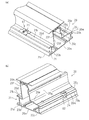
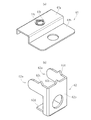
図4(a)(b)はアース部材61・62を備えた横桟部材20について示す斜視図、図5は横桟部材20に太陽電池パネル3・3の端部を設置した状態について示す断面図、図6(a)(b)はアース部材61・62の部品図である。
まず、図4(a)(b)及び図5に示すごとく、横桟部材20は、押し出し成型品などからなる中空の部材であって、素材をアルミなどの金属とするものであり、導電性を有するものとなっている。横桟部材20は、その断面視において、縦桟部材10の上面に載置される底面部20aと、底面部20aの両端部から上方に立ち上がる縦面部20b・20cと、各縦面部20b・20cの上端から互いに近づくように延設される横面部20d・20eと、横面部20d・20eの対向する端部から上方に立ち上がる縦面部20f・20gと、縦面部20f・20gの上端部を結ぶように設けられる上面部20hと、を有する構成としている。
Next, a configuration related to ground connection will be described.
4 (a) and 4 (b) are perspective views showing the
First, as shown in FIGS. 4 (a), 4 (b) and 5, the
また、図4(a)(b)及び図5に示すごとく、図において左側の縦面部20bには、整線用部材51を取付けるための取付用溝部21が形成されている。この取付用溝部21は、縦面部20bにおいて、その下端、及び、上端から、それぞれ下側面部21a、上側面部21bを突出させることで、横側が開放される略コ字状をなす溝にて構成されており、この開放部からトレイ状の整線用部材51(図5)が取付けられるようになっている。
Further, as shown in FIGS. 4 (a), 4 (b) and 5, a mounting
また、図4(a)(b)及び図5に示すごとく、横桟部材20において、取付用溝部21を形成する上側面部21bには、隣り合う一方の太陽電池パネル3の端部が載置されるようになっており、この上側面部21bが、太陽電池パネル3を下側から支持する支持部として機能するようになっている。また、上側面部21bは、太陽電池パネル3の下部3aに対向する対向部(上側面部21b)として機能するようになっている。また、上側面部21bの上面には、アース部材61が取付られており、太陽電池パネル3と上側面部21bの間に、アース部材61の一部が挟装されるようになっている。
Further, as shown in FIGS. 4A, 4B and 5, in the
また、図4(a)(b)及び図5に示すごとく、横桟部材20において、横面部20eには、隣り合う他方の太陽電池パネル3の端部が載置されるようになっており、この横面部20eが、太陽電池パネル3を下側から支持する支持部として機能するようになっている。また、横面部20eは、太陽電池パネル3の下部3aに対向する対向部(横面部20e)として機能するようになっている。また、横桟部材20において、縦面部20cの上部には、横面部20eと反対側方向に延出される上下二段の取付片部20j・20kが延設されており、この取付片部20j・20kに、アース部材62が取付られている。この構成により、太陽電池パネル3と取付片部20jの間に、アース部材62の一部が挟装されるようになっている。
Further, as shown in FIGS. 4A, 4B and 5, in the
また、図4(b)、図5及び図6(a)に示すごとく、アース部材61は、太陽電池パネル3側(例えば、太陽電池パネルを囲む金属フレーム)と、横桟部材20側(上側面部21b)を導通させるための部材であって、導電性を有する素材(例えば、ステンレス)にて構成される。アース部材61は、板状の部材にて構成され、太陽電池パネル3(図5)と横桟部材20(上側面部21b)の間に挟装されるための被挟装部61aと、横桟部材20の横面部20dに対してビスなどの締結具23で固定される固定部61bを有して構成される。
Further, as shown in FIGS. 4B, 5 and 6A, the
また、図5に示すごとく、アース部材61と導通をさせる対象となる太陽電池パネル3、及び、横桟部材20において、その外表面は腐食防止のためにアルマイト処理や、塗装などが施されるため、これら塗膜(絶縁皮膜)によって電気的に絶縁されることとなっている。そして、この塗膜による絶縁を無くし、アース部材61を介して太陽電池パネル3側と横桟部材20側を電気的に導通をさせるために、図6(a)に示すごとく、アース部材61の被挟装部61aの上面側には、太陽電池パネル側の塗膜に対し刺衝され、金属の導通部(例えば、パネルを囲む金属性のユニット枠など)に到達するための、突起部61cが設けられる構成としている。これにより、アース部材61に太陽電池パネルの端部が載置された場合には、突起部61cが塗膜を突き破って太陽電池パネル側の金属の導通部(例えば、パネルを囲む金属性のユニット枠など)に接触し、アース部材61と太陽電池パネルの電気的な導通が確保される。
Further, as shown in FIG. 5, the outer surface of the
また、図4(a)、図5、及び、図6(a)に示すごとく、アース部材61と横桟部材20の電気的な導通は、アース部材61の固定部61bが、金属製の締結具23を介して横面部20dに対して固定されることで、締結具23を介してアース部材61と横桟部材20の電気的な導通を確保することができる。
Further, as shown in FIGS. 4A, 5 and 6A, the electrical connection between the
同様に、図4(b)、図5及び図6(b)に示すごとく、アース部材62は、図5に示すもう一方の太陽電池パネル3側(例えば、太陽電池パネルを囲む金属フレーム)と、横桟部材20側(縦面部20c、取付片部20j・20k)を導通させるための部材であって、導電性を有する素材(例えば、ステンレス)にて構成される。アース部材62は、側面視略コ字状をなす部材にて構成され、太陽電池パネル3(図5)と横桟部材20(取付片部20j)の間に挟装されるための横方向に二つの被挟装部62a・62aと、横桟部材20の縦面部20cに対してビスなどの締結具24で固定され、被挟装部62a・62aを突出させる固定部62bを有して構成される。また、固定部62bにおいて被挟装部62a・62aと反対側の端部には、突片部62dが設けられており、この突片部62dと被挟装部62a・62aの間に、取付片部20j・20k(図4(b)参照)が挟装されるようになっている。なお、図4(b)及び図5に示すごとく、取付片部20j・20kにて溝部20mが形成され、この溝部20mに締結具24が螺挿されることで、締結具24は、取付片部20j・20k、及び、縦面部20cに対して電気的に導通されることになる。
Similarly, as shown in FIG. 4B, FIG. 5 and FIG. 6B, the
また、図4(b)、図5及び図6(b)に示すごとく、アース部材62の被挟装部62a・62a、及び、固定部62bの上面側には、太陽電池パネル3側の塗膜に対し刺衝され、金属の導通部に到達するための、突起部62c・62cが設けられる構成としている。これにより、アース部材62に太陽電池パネルの端部が載置された場合には、突起部62c・62cが塗膜を突き破って太陽電池パネル側の金属の導通部に接触し、アース部材62と太陽電池パネルの電気的な導通が確保される。
Further, as shown in FIGS. 4B, 5 and 6B, the top surface of the sandwiched
そして、図4(b)、図5、及び、図6(b)に示すごとく、アース部材62と横桟部材20の電気的な導通は、アース部材62の固定部62bが、金属製の締結具24を介して取付片部20j・20kに対して固定されることで、締結具24を介してアース部材62と横桟部材20の電気的な導通を確保することができる。
As shown in FIGS. 4 (b), 5 and 6 (b), the electrical connection between the
以上のようにして、図7に示すごとく、縦桟部材10の長手方向(縦方向)に隣り合う太陽電池パネル3・3は、アース部材61・62、横桟部材20などを介して電気的に導通される。また、図において横方向の列A1と列A3の間に列A2が介在することになるが、この列A2を構成する太陽電池パネル3・3が導電体となって、列A1と列A3を電気的に導通させることになる。さらに、横桟部材20の長手方向(横方向)に隣り合う太陽電池パネル3・3についても、横方向に並ぶアース部材61・61、横桟部材20(アース部材62・62、横桟部材20)を介して電気的に導通されることになる。つまり、縦方向、横方向のそれぞれに隣り合う太陽電池パネル3・3同士が、アース部材61・62、横桟部材20、及び、太陽電池パネル3・3そのもの、介して電気的に導通され、各太陽電池パネル3・3同士をアースケーブルを使用せずに導通させることができる。そして、これにより、例えば、横桟部材20の一箇所にのみアースケーブル9を接続するなどにより、アース接続を実施することが可能となる。
As described above, as shown in FIG. 7, the
以上が本発明の実施形態であり、本発明を以下の内容とすることができる。
即ち、図7に示すごとく、
太陽電池パネル3・3などの太陽エネルギー利用装置の接地構造であって、
前記太陽エネルギー利用装置を設置する架台を構成する架台用桟部材としての横桟部材20が、
前記太陽エネルギー利用装置としての太陽電池パネル3・3の下部3Aに対向する対向部(上側面部21b、横面部20e)を有し、
前記対向部(上側面部21b、横面部20e)と、前記下部3Aの間には、
前記下部3Aと、前記架台用桟部材としての横桟部材20の間を導通させるための少なくとも一つのアース部材61・62が設けられ、
前記架台用桟部材としての横桟部材20に前記太陽エネルギー利用装置としての太陽電池パネル3・3が載置された際に、
前記下部3Aと、前記架台用桟部材としての横桟部材20の電気的な導通が、前記アース部材61・62を介して行われ得る、
こととするものである。
The above is the embodiment of the present invention, and the present invention can have the following contents.
That is, as shown in FIG.
A grounding structure for solar energy utilization devices such as
A
It has a facing part (
Between the facing portion (upper
At least one
When the
Electrical conduction between the
It is something to do.
これにより、架台用桟部材に太陽エネルギー利用装置を設置するだけで、両者間の電気的な導通をアースケーブルを用いずに実現することが可能となる。また、作業者による施工のばらつきの発生が抑制されるとともに、アース接続に関する作業を短時間で実施することができるため、施工性に優れた構造が実現できる。 Thereby, it becomes possible to implement | achieve the electrical continuity between both, without using a ground cable only by installing a solar energy utilization apparatus in the crosspiece member. In addition, the occurrence of variations in construction by the operator is suppressed, and work related to ground connection can be performed in a short time, so that a structure with excellent workability can be realized.
また、図7に示すごとく、
前記アース部材61・62は、複数箇所に設けられるものであって、
前記各アース部材61・62は、太陽エネルギー利用装置を構成する複数のユニット(太陽電池パネル3・3)のそれぞれについて、個別に設けられるものであり、
前記各ユニット(太陽電池パネル3・3)同士は、前記架台用桟部材としての横桟部材20、及び、前記アース部材61・62を介して電気的に導通される、
こととするものである。
Moreover, as shown in FIG.
The
Each of the
The units (
It is something to do.
これにより、前記各ユニット(太陽電池パネル3・3)間の電気的な導通をアースケーブルを用いずに実現することが可能となる。また、作業者による施工のばらつきの発生が抑制されるとともに、アース接続に関する作業を短時間で実施することができるため、施工性に優れた構造が実現できる。
Thereby, it is possible to realize electrical continuity between the units (
また、図1及び図7に示すごとく、
前記各ユニット(太陽電池パネル3・3)は、縦方向、及び、横方向に配列されるものであり、
前記架台用桟部材としての横桟部材20、及び、前記アース部材を介して、各ユニット(太陽電池パネル3・3)の間での縦方向、及び、横方向の電気的な導通がなされることにより、
全ての前記ユニット間(太陽電池パネル3・3)での電気的な導通が確保される、
こととするものである。
Moreover, as shown in FIG.1 and FIG.7,
The units (
Electrical conduction in the vertical direction and the horizontal direction is made between the units (
Electrical continuity between all the units (
It is something to do.
これにより、全てのユニット(太陽電池パネル3・3)間の電気的な導通をアースケーブルを用いずに実現することが可能となる。また、作業者による施工のばらつきの発生が抑制されるとともに、アース接続に関する作業を短時間で実施することができるため、施工性に優れた構造が実現できる。
Thereby, it becomes possible to implement | achieve the electrical continuity between all the units (
また、図1、図4(a)(b)、及び、図7に示すごとく、
太陽電池パネル3・3などの太陽エネルギー利用装置を設置するための架台を構成するための、導電機能を有する架台用桟部材(横桟部材20)であって、
前記太陽エネルギー利用装置としての太陽電池パネル3・3の下部3Aに対向する対向部(上側面部21b、横面部20e)を有し、
前記(上側面部21b、横面部20e)には、少なくとも一つのアース部材61・62が設けられ、
前記架台用桟部材としての横桟部材20に前記太陽エネルギー利用装置としての太陽電池パネル3・3が載置された際に、
前記下部3Aと、前記架台用桟部材としての横桟部材20の電気的な導通が、前記アース部材61・62を介して行われ得る、
こととするものである。
Moreover, as shown in FIG. 1, FIG. 4 (a) (b), and FIG.
A pedestal beam member (horizontal beam member 20) having a conductive function for constituting a gantry for installing solar energy utilization devices such as
It has a facing part (
The (upper
When the
Electrical conduction between the
It is something to do.
これにより、架台用桟部材に太陽エネルギー利用装置を設置するだけで、両者間の電気的な導通をアースケーブルを用いずに実現することが可能となる。また、作業者による施工のばらつきの発生が抑制されるとともに、アース接続に関する作業を短時間で実施することができるため、施工性に優れた構造が実現できる。 Thereby, it becomes possible to implement | achieve the electrical continuity between both, without using a ground cable only by installing a solar energy utilization apparatus in the crosspiece member. In addition, the occurrence of variations in construction by the operator is suppressed, and work related to ground connection can be performed in a short time, so that a structure with excellent workability can be realized.
本発明の構成は、建物の屋根などに設置される太陽電池パネルなどの太陽エネルギー利用装置において、アース接続をするための手段として幅広く適用することができる。 The configuration of the present invention can be widely applied as a means for ground connection in a solar energy utilization device such as a solar cell panel installed on the roof of a building.
1 屋根
1A 屋根材
2 太陽エネルギー利用装置
3 太陽電池パネル
4 架台
9 アースケーブル
10 縦桟部材
20 横桟部材
21 取付用溝部
30 支持部材
51 整線用部材
61 アース部材
62 アース部材
DESCRIPTION OF SYMBOLS 1
Claims (2)
前記太陽エネルギー利用装置を設置する架台を構成する架台用桟部材には、架台用桟部材の両側にそれぞれ前記太陽エネルギー利用装置が載置される対向部が設けられ、
前記各対向部には、それぞれアース部材が締結具にて予め固定されており、
前記架台用桟部材の一方の対向部に一方の前記太陽エネルギー利用装置を載置することで、一方の前記アース部材を介して前記太陽エネルギー利用装置の下部と前記架台用桟部材が電気的に導通され、
前記架台用桟部材の他方の対向部に他方の前記太陽エネルギー利用装置を載置することで、他方の前記アース部材を介して前記太陽エネルギー利用装置の下部と前記架台用桟部材が電気的に導通される、
太陽エネルギー利用装置の接地方法。 A method of grounding a solar energy utilization device,
The frame member for the frame that constitutes the frame on which the solar energy utilization device is installed is provided with opposing portions on which the solar energy utilization device is placed on both sides of the frame member for the frame ,
In each of the facing portions, a grounding member is fixed in advance with a fastener, respectively .
By placing one of the solar energy utilization devices on one opposite portion of the gantry beam member, the lower part of the solar energy utilization device and the gantry beam member are electrically connected to each other via the one earth member. It is conducting,
By placing the other solar energy utilization device on the other opposing portion of the gantry beam member, the lower part of the solar energy utilization device and the gantry beam member are electrically connected via the other earth member. Conducted,
A method for grounding solar energy equipment.
Priority Applications (1)
| Application Number | Priority Date | Filing Date | Title |
|---|---|---|---|
| JP2011007468A JP5773657B2 (en) | 2011-01-18 | 2011-01-18 | Method of grounding solar energy utilization device and pedestal beam member used therefor |
Applications Claiming Priority (1)
| Application Number | Priority Date | Filing Date | Title |
|---|---|---|---|
| JP2011007468A JP5773657B2 (en) | 2011-01-18 | 2011-01-18 | Method of grounding solar energy utilization device and pedestal beam member used therefor |
Publications (2)
| Publication Number | Publication Date |
|---|---|
| JP2012149402A JP2012149402A (en) | 2012-08-09 |
| JP5773657B2 true JP5773657B2 (en) | 2015-09-02 |
Family
ID=46791897
Family Applications (1)
| Application Number | Title | Priority Date | Filing Date |
|---|---|---|---|
| JP2011007468A Active JP5773657B2 (en) | 2011-01-18 | 2011-01-18 | Method of grounding solar energy utilization device and pedestal beam member used therefor |
Country Status (1)
| Country | Link |
|---|---|
| JP (1) | JP5773657B2 (en) |
Families Citing this family (8)
| Publication number | Priority date | Publication date | Assignee | Title |
|---|---|---|---|---|
| JP2014211011A (en) * | 2013-04-17 | 2014-11-13 | ニイガタ製販株式会社 | Solar panel mounting metal fitting |
| US9813014B2 (en) * | 2013-10-31 | 2017-11-07 | Kyocera Corporation | Solar cell array |
| TWM482160U (en) * | 2013-11-26 | 2014-07-11 | Hulk Energy Technology Co Ltd | Solar cell module array of grounding device |
| JP5740514B1 (en) * | 2014-06-09 | 2015-06-24 | 株式会社ブレスト工業研究所 | Conductive bracket for solar cell module |
| JP6542161B2 (en) * | 2016-06-28 | 2019-07-10 | 株式会社サンレール | Photovoltaic panel mount |
| JP6878151B2 (en) * | 2017-05-31 | 2021-05-26 | 大和ハウス工業株式会社 | Roof structure |
| JP7020815B2 (en) * | 2017-08-03 | 2022-02-16 | 株式会社Lixil | Solar power generator |
| JP7086550B2 (en) * | 2017-09-19 | 2022-06-20 | 東洋アルミニウム株式会社 | How to install the solar cell module |
Family Cites Families (2)
| Publication number | Priority date | Publication date | Assignee | Title |
|---|---|---|---|---|
| JP4311341B2 (en) * | 2004-11-16 | 2009-08-12 | パナソニック電工株式会社 | Function panel mounting structure |
| JP5202430B2 (en) * | 2009-05-11 | 2013-06-05 | 株式会社屋根技術研究所 | Solar cell module fixing structure |
-
2011
- 2011-01-18 JP JP2011007468A patent/JP5773657B2/en active Active
Also Published As
| Publication number | Publication date |
|---|---|
| JP2012149402A (en) | 2012-08-09 |
Similar Documents
| Publication | Publication Date | Title |
|---|---|---|
| JP5773657B2 (en) | Method of grounding solar energy utilization device and pedestal beam member used therefor | |
| US8935893B2 (en) | Direct rooftop mounting apparatus for solar panels | |
| US9276519B2 (en) | Securing structure for solar cell module | |
| US8806813B2 (en) | Technique for electrically bonding solar modules and mounting assemblies | |
| WO2010082355A1 (en) | Solar cell fixing device | |
| JP4721081B1 (en) | Support and fixing structure of solar energy device | |
| US20120222718A1 (en) | Photovoltaic grounding & bonding connector | |
| US9528725B2 (en) | Solar panel frame clamps mounting a solar panel frame to a purlin | |
| US10103688B2 (en) | Systems and methods for improved installation and grounding of photovoltaic assemblies | |
| JP2002146978A (en) | Module fitting structure for shingle roof and module fitting holder | |
| CN112787590A (en) | Panel equipped with photovoltaic device | |
| JP4829259B2 (en) | Method for forming solar cell module fixing device | |
| US8672702B2 (en) | Electrical conductor arrangement as a component of a photovoltaic array | |
| JP2003213854A (en) | Fixing device for solar battery panel | |
| US8656661B2 (en) | Connection device for photovoltaic modules and method for installing same | |
| JP4659072B2 (en) | Solar cell installation structure and installation method | |
| JP2002364136A (en) | Construction method of solar battery panel, and construction equipment and material for solar battery panel | |
| CN202949045U (en) | Photovoltaic assembly grounding device | |
| JP5725499B2 (en) | Mounting member, photovoltaic power generation system and mounting method | |
| JP6633865B2 (en) | Solar cell module fixing member, solar power generation system, solar cell module fixing structure, and solar cell module fixing method | |
| JP2016098595A (en) | Power generation panel fixture | |
| KR20140072932A (en) | The Sunlight Panel Supporter For Arch Panel Roof | |
| RU209955U1 (en) | Clamp for lightning protection and grounding | |
| JP2012112127A (en) | Mounting member | |
| JP5993624B2 (en) | Snow clasp, solar cell module, and method for laying solar cell module |
Legal Events
| Date | Code | Title | Description |
|---|---|---|---|
| A621 | Written request for application examination |
Free format text: JAPANESE INTERMEDIATE CODE: A621 Effective date: 20130924 |
|
| A977 | Report on retrieval |
Free format text: JAPANESE INTERMEDIATE CODE: A971007 Effective date: 20140612 |
|
| A131 | Notification of reasons for refusal |
Free format text: JAPANESE INTERMEDIATE CODE: A131 Effective date: 20140618 |
|
| A521 | Request for written amendment filed |
Free format text: JAPANESE INTERMEDIATE CODE: A523 Effective date: 20140728 |
|
| A131 | Notification of reasons for refusal |
Free format text: JAPANESE INTERMEDIATE CODE: A131 Effective date: 20150119 |
|
| A521 | Request for written amendment filed |
Free format text: JAPANESE INTERMEDIATE CODE: A523 Effective date: 20150224 |
|
| TRDD | Decision of grant or rejection written | ||
| A01 | Written decision to grant a patent or to grant a registration (utility model) |
Free format text: JAPANESE INTERMEDIATE CODE: A01 Effective date: 20150630 |
|
| A61 | First payment of annual fees (during grant procedure) |
Free format text: JAPANESE INTERMEDIATE CODE: A61 Effective date: 20150630 |
|
| R150 | Certificate of patent or registration of utility model |
Ref document number: 5773657 Country of ref document: JP Free format text: JAPANESE INTERMEDIATE CODE: R150 |
|
| S111 | Request for change of ownership or part of ownership |
Free format text: JAPANESE INTERMEDIATE CODE: R313111 |
|
| R350 | Written notification of registration of transfer |
Free format text: JAPANESE INTERMEDIATE CODE: R350 |
|
| R250 | Receipt of annual fees |
Free format text: JAPANESE INTERMEDIATE CODE: R250 |