JP5773423B2 - Wireless communication device, network, wireless communication method and program - Google Patents
Wireless communication device, network, wireless communication method and program Download PDFInfo
- Publication number
- JP5773423B2 JP5773423B2 JP2011132314A JP2011132314A JP5773423B2 JP 5773423 B2 JP5773423 B2 JP 5773423B2 JP 2011132314 A JP2011132314 A JP 2011132314A JP 2011132314 A JP2011132314 A JP 2011132314A JP 5773423 B2 JP5773423 B2 JP 5773423B2
- Authority
- JP
- Japan
- Prior art keywords
- data
- transmission
- communication
- packet
- wireless communication
- Prior art date
- Legal status (The legal status is an assumption and is not a legal conclusion. Google has not performed a legal analysis and makes no representation as to the accuracy of the status listed.)
- Active
Links
- 238000004891 communication Methods 0.000 title claims description 358
- 238000000034 method Methods 0.000 title claims description 55
- 230000005540 biological transmission Effects 0.000 claims description 365
- 238000012360 testing method Methods 0.000 claims description 78
- 238000001514 detection method Methods 0.000 claims description 72
- 238000004364 calculation method Methods 0.000 claims description 39
- 238000012545 processing Methods 0.000 claims description 36
- 238000011156 evaluation Methods 0.000 claims description 22
- 230000008569 process Effects 0.000 claims description 19
- 230000008859 change Effects 0.000 claims description 12
- 230000002159 abnormal effect Effects 0.000 claims 2
- 238000007726 management method Methods 0.000 description 57
- 238000010586 diagram Methods 0.000 description 14
- 238000004422 calculation algorithm Methods 0.000 description 9
- 230000035945 sensitivity Effects 0.000 description 7
- 238000007635 classification algorithm Methods 0.000 description 6
- 238000002360 preparation method Methods 0.000 description 5
- 101100172132 Mus musculus Eif3a gene Proteins 0.000 description 3
- 238000005259 measurement Methods 0.000 description 3
- 230000005856 abnormality Effects 0.000 description 2
- 230000008901 benefit Effects 0.000 description 2
- 238000002474 experimental method Methods 0.000 description 2
- 238000000605 extraction Methods 0.000 description 2
- 230000006870 function Effects 0.000 description 2
- 238000005549 size reduction Methods 0.000 description 2
- 238000012790 confirmation Methods 0.000 description 1
- 230000007423 decrease Effects 0.000 description 1
- 238000005516 engineering process Methods 0.000 description 1
- 238000009434 installation Methods 0.000 description 1
- 238000000691 measurement method Methods 0.000 description 1
- 230000003449 preventive effect Effects 0.000 description 1
- 238000010187 selection method Methods 0.000 description 1
Images


Classifications
-
- H—ELECTRICITY
- H04—ELECTRIC COMMUNICATION TECHNIQUE
- H04W—WIRELESS COMMUNICATION NETWORKS
- H04W24/00—Supervisory, monitoring or testing arrangements
- H04W24/06—Testing, supervising or monitoring using simulated traffic
-
- H—ELECTRICITY
- H04—ELECTRIC COMMUNICATION TECHNIQUE
- H04L—TRANSMISSION OF DIGITAL INFORMATION, e.g. TELEGRAPHIC COMMUNICATION
- H04L41/00—Arrangements for maintenance, administration or management of data switching networks, e.g. of packet switching networks
- H04L41/06—Management of faults, events, alarms or notifications
- H04L41/0654—Management of faults, events, alarms or notifications using network fault recovery
-
- H—ELECTRICITY
- H04—ELECTRIC COMMUNICATION TECHNIQUE
- H04L—TRANSMISSION OF DIGITAL INFORMATION, e.g. TELEGRAPHIC COMMUNICATION
- H04L43/00—Arrangements for monitoring or testing data switching networks
- H04L43/08—Monitoring or testing based on specific metrics, e.g. QoS, energy consumption or environmental parameters
- H04L43/0805—Monitoring or testing based on specific metrics, e.g. QoS, energy consumption or environmental parameters by checking availability
-
- H—ELECTRICITY
- H04—ELECTRIC COMMUNICATION TECHNIQUE
- H04W—WIRELESS COMMUNICATION NETWORKS
- H04W24/00—Supervisory, monitoring or testing arrangements
- H04W24/02—Arrangements for optimising operational condition
-
- H—ELECTRICITY
- H04—ELECTRIC COMMUNICATION TECHNIQUE
- H04W—WIRELESS COMMUNICATION NETWORKS
- H04W88/00—Devices specially adapted for wireless communication networks, e.g. terminals, base stations or access point devices
- H04W88/02—Terminal devices
-
- H—ELECTRICITY
- H04—ELECTRIC COMMUNICATION TECHNIQUE
- H04W—WIRELESS COMMUNICATION NETWORKS
- H04W74/00—Wireless channel access, e.g. scheduled or random access
- H04W74/08—Non-scheduled or contention based access, e.g. random access, ALOHA, CSMA [Carrier Sense Multiple Access]
- H04W74/0808—Non-scheduled or contention based access, e.g. random access, ALOHA, CSMA [Carrier Sense Multiple Access] using carrier sensing, e.g. as in CSMA
- H04W74/0825—Non-scheduled or contention based access, e.g. random access, ALOHA, CSMA [Carrier Sense Multiple Access] using carrier sensing, e.g. as in CSMA carrier sensing with collision detection
Description
本発明は、無線通信機、ネットワーク、無線通信方法、およびその方法をコンピュータに実行させるためのプログラムに関する。 The present invention relates to a wireless communication device, a network, a wireless communication method, and a program for causing a computer to execute the method.
近年、無線LAN(Local Area Network)通信が、企業の職場だけでなく、家庭内や屋外などの広い範囲に普及してきた。無線LANの普及に伴い、限られた周波数資源での通信量が増加し、互いの通信の干渉問題が深刻になってきた。 In recent years, wireless LAN (Local Area Network) communication has become widespread not only in corporate workplaces but also in a wide range such as home and outdoors. With the widespread use of wireless LANs, the amount of communication using limited frequency resources has increased, and the problem of mutual interference has become serious.
無線LAN規格の1つであるIEEE802.11では、衝突回避機能付きキャリア感知多重アクセス(Carrier Sense Multiple Access with Collision Avoidance:CSMA/CA)のアクセス制御方法が使用されている(非特許文献1参照)。このアクセス制御方法は、通信を開始しようとする各無線通信機は、通信を開始する前に周りの無線通信機が電波を出していないかを、必ず確認してから通信を開始する方法である。 IEEE 802.11, which is one of the wireless LAN standards, uses an access control method of carrier sense multiple access with collision avoidance function (CSMA / CA) (see Non-Patent Document 1). . This access control method is a method in which each wireless communication device that is about to start communication always checks whether the surrounding wireless communication device is emitting radio waves before starting communication, and then starts communication. .
また、上記アクセス制御方法では、通信衝突を回避するために、無線通信機は、周囲の機器(他の無線通信機)が電波を出していれば、ある一定期間(バックオフ時間)だけ待った後、電波が出ていないかを再び調べ、周囲の機器が電波を出していなければ、あるランダムな時間経過後に自分が電波を送信する。無線通信機は、周囲の機器が電波を出していないかを確認するために、キャリアセンスを使用する。 In the above access control method, in order to avoid a communication collision, the wireless communication device waits for a certain period (back-off time) if surrounding devices (other wireless communication devices) emit radio waves. Check again if there is no radio wave, and if the surrounding devices do not emit radio waves, they will send radio waves after a certain random time. The wireless communication device uses carrier sense in order to check whether or not surrounding devices emit radio waves.
キャリアセンスは、無線チャネルの使用状況を確認し、IEEE802.11の規格に合う信号のプリアンプル(同期を確立するための信号)を検出した場合は、信号の受信を行うので無線チャネル使用中(Busy:ビジー)となる。IEEE802.11の規格に合う信号のプリアンプルを検出できなかった場合で、予め設定されたキャリアセンス閾値より高い電力レベルが検出されたときは、ビジーと判断し、送信を待機する。また、キャリアセンス閾値より低い電力レベルが検出されたときは、無線チャネルが未使用(アイドル)と判断される。 Carrier sense confirms the usage status of the radio channel, and when a signal preamplifier (signal for establishing synchronization) that conforms to the IEEE 802.11 standard is detected, the signal is received, so the radio channel is in use ( Busy: busy). When a signal preamplifier that conforms to the IEEE 802.11 standard cannot be detected and a power level higher than a preset carrier sense threshold is detected, it is determined to be busy and transmission is waited for. When a power level lower than the carrier sense threshold is detected, it is determined that the radio channel is unused (idle).
上述したアクセス制御方法には、次のような問題があった。以下では、IEEE802.11を満たす無線通信機を「802.11無線機」と表記する。 The access control method described above has the following problems. Hereinafter, a wireless communication device that satisfies IEEE 802.11 is referred to as an “802.11 wireless device”.
802.11無線機の送受信制御に使用されているCSMA/CAは、外部干渉によるパケットの衝突を完全には回避できないという問題がある。しかもパケット衝突の検出ができないため、パケット衝突による通信失敗が起こった場合、通信失敗の原因の確定ができず、通信失敗に対して有効な防止策を立てられない。また、外部干渉によりパケットが衝突する場合、衝突率を定量的に統計する手段がないため、正確に衝突の度合を評価するのは難しい。 The CSMA / CA used for transmission / reception control of 802.11 wireless devices has a problem that packet collision due to external interference cannot be completely avoided. In addition, since a packet collision cannot be detected, when a communication failure occurs due to a packet collision, the cause of the communication failure cannot be determined, and an effective preventive measure against the communication failure cannot be established. In addition, when a packet collides due to external interference, it is difficult to accurately evaluate the degree of collision because there is no means for quantitatively statistics the collision rate.
パケット衝突の検出方法として、信号の送信と同時に伝送路上の信号を観測し、観測された信号から送信信号を除去し、送信信号が除去した後の信号のエネルギー量に基づいて、伝送路上の信号衝突の有無を判定する衝突検出方法が特許文献1に開示されている。また、パケット衝突に関する別の検出方法として、近傍に存在する無線端末数および無線伝送速度等に基づいて、データの衝突確率を算出することが特許文献2に開示されている。
As a packet collision detection method, the signal on the transmission line is observed simultaneously with the transmission of the signal, the transmission signal is removed from the observed signal, and the signal on the transmission line is determined based on the energy amount of the signal after the transmission signal is removed.
特許文献1に開示された方法では、送信信号以外の干渉信号の有無を判定できるが、観測された干渉信号は受信側の受信を干渉するかどうか判定できない。また、送信側で観測できない信号が受信側での受信を干渉するおそれもあり、その干渉についても検出できない。
With the method disclosed in
特許文献2に開示された方法では、データの衝突確率は予測される無線状況から算出されており、予測された無線状況が実際の無線状況と大きく異なっている場合、算出される衝突確率は実際の無線状況と合わないものになってしまう。特許文献1および2に開示された方法は、パケット衝突の検出精度が不十分であり、データの伝送効率を向上させるための対策を取れない。
In the method disclosed in
また、無線LAN通信では外部干渉からの影響は干渉距離や干渉波の電力強度によって異なり、802.11無線機では、これらの異なる干渉状況を正確に把握できないという問題もある。その結果、干渉状況に合わせてデータの伝送効率を向上させるための対策を取ることができない。 Further, in wireless LAN communication, the influence of external interference varies depending on the interference distance and the power intensity of the interference wave, and there is a problem that the 802.11 wireless device cannot accurately grasp these different interference situations. As a result, it is not possible to take measures to improve the data transmission efficiency in accordance with the interference situation.
本発明は上述したような技術が有する問題点を解決するためになされたものであり、他の通信との干渉を抑制し、データの伝送効率を向上させることを可能にした無線通信機、ネットワーク、無線通信方法、およびその方法をコンピュータに実行させるためのプログラムを提供することを目的とする。 The present invention has been made in order to solve the problems of the above-described technology, and suppresses interference with other communications and improves data transmission efficiency and a wireless communication apparatus and network. An object of the present invention is to provide a wireless communication method and a program for causing a computer to execute the method.
上記目的を達成するための本発明の無線通信機は、
前記複数のテスト用パケットと同じ周波数チャネルで空間電波信号の電力をセンシングし、センシングした空間電波信号のサンプルデータを出力する信号センシング部と、
前記信号センシング部から出力されるサンプルデータを、該サンプルデータが時系列にプロットされたデータである時系列サンプルデータに変換する計算処理部と、
前記時系列サンプルデータに基づいて前記複数のテスト用パケットと他の通信との干渉によるパケット衝突があると判定すると、パケット衝突の回数と前記複数のテスト用パケットの送信数とからパケット衝突率を算出する衝突検出部と、
前記データ送受信部がデータ送信を行う際のパラメータを、前記衝突検出部の算出結果に基づいて調整する制御部と、
を有する構成である。
In order to achieve the above object, a wireless communication device of the present invention comprises:
A signal sensing unit that senses the power of the spatial radio signal in the same frequency channel as the plurality of test packets, and outputs sample data of the sensed spatial radio signal;
A calculation processing unit that converts the sample data output from the signal sensing unit into time-series sample data in which the sample data is plotted in time series;
When it is determined that there is a packet collision due to interference between the plurality of test packets and other communication based on the time-series sample data, a packet collision rate is calculated from the number of packet collisions and the number of transmissions of the plurality of test packets. A collision detection unit to calculate,
A control unit that adjusts parameters when the data transmission / reception unit performs data transmission based on a calculation result of the collision detection unit;
It is the structure which has.
また、本発明の無線通信機は、
無線によるパケットの送受信に伴って、パケットの送受信に関するパラメータである送受信パラメータの統計処理を行うデータ送受信部と、
前記データ送受信部で算出された、前記送受信パラメータの統計処理の結果から、自機がパケットの送受信で使用するチャネルと同一のチャネルが使用されていると判断される時間の割合であるビジー率、パケット送信成功率、および該パケット送信成功率の標準偏差を含む通信評価用パラメータを算出する計算処理部と、
前記計算処理部が算出した前記通信評価用パラメータに基づいて、他の通信との干渉による影響度を示す通信状態を判定する通信状態分類部と、
前記データ送受信部がデータ送信を行う際のパラメータを、前記通信状態分類部が判定した通信状態に対応して調整する制御部と、
を有する構成である。
The wireless communication device of the present invention is
A data transmission / reception unit that performs statistical processing of transmission / reception parameters, which are parameters related to packet transmission / reception, accompanied by wireless packet transmission / reception,
From the result of statistical processing of the transmission / reception parameters calculated by the data transmission / reception unit, a busy rate that is a ratio of time when it is determined that the same channel as the channel used by the own device for transmission / reception of packets is used, A calculation processor for calculating a communication evaluation parameter including a packet transmission success rate and a standard deviation of the packet transmission success rate;
Based on the communication evaluation parameter calculated by the calculation processing unit, a communication state classification unit that determines a communication state indicating the degree of influence due to interference with other communication;
A control unit that adjusts a parameter when the data transmission / reception unit performs data transmission according to the communication state determined by the communication state classification unit;
It is the structure which has.
また、本発明のネットワークは、本発明の無線通信機が基地局として複数配置された構成である。 Further, the network of the present invention has a configuration in which a plurality of wireless communication apparatuses of the present invention are arranged as base stations.
また、本発明の無線通信方法は、
複数のテスト用パケットを無線で送出し、
前記複数のテスト用パケットと同じ周波数チャネルで空間電波信号の電力をセンシングし、
センシングした空間電波信号のサンプルデータを、該サンプルデータが時系列にプロットされたデータである時系列サンプルデータに変換し、
前記時系列サンプルデータに基づいて前記複数のテスト用パケットと他の通信との干渉によるパケット衝突があると判定すると、パケット衝突の回数と前記複数のテスト用パケットの送信数とからパケット衝突率を算出し、
前記パケット衝突率に基づいて、データ送信を行う際のパラメータを調整するものである。
The wireless communication method of the present invention includes
Send multiple test packets wirelessly,
Sensing the power of the spatial radio signal in the same frequency channel as the plurality of test packets,
The sampled data of the sensed spatial radio signal is converted to time-series sample data, which is data plotted in time series,
When it is determined that there is a packet collision due to interference between the plurality of test packets and other communication based on the time-series sample data, a packet collision rate is calculated from the number of packet collisions and the number of transmissions of the plurality of test packets. Calculate
Based on the packet collision rate, parameters for performing data transmission are adjusted.
また、本発明の無線通信方法は、
無線によるパケットの送受信に伴って、パケットの送受信に関するパラメータである送受信パラメータの統計処理を行い、
前記送受信パラメータの統計処理の結果から、自機がパケットの送受信で使用するチャネルと同一のチャネルが使用されていると判断される時間の割合であるビジー率、パケット送信成功率、および該パケット送信成功率の標準偏差を含む通信評価用パラメータを算出し、
前記通信評価用パラメータに基づいて、他の通信との干渉による影響度を示す通信状態を判定し、
前記判定した通信状態に対応して、データ送信を行う際のパラメータを調整するものである。
The wireless communication method of the present invention includes
Along with wireless packet transmission and reception, statistical processing of transmission and reception parameters that are parameters related to packet transmission and reception is performed.
From the result of the statistical processing of the transmission / reception parameters, the busy rate, the packet transmission success rate, and the packet transmission, which are ratios of the time when it is determined that the same channel as the channel used by the own device for packet transmission / reception is used. Calculate communication evaluation parameters including standard deviation of success rate,
Based on the communication evaluation parameters, determine a communication state indicating the degree of influence due to interference with other communication,
Corresponding to the determined communication state, parameters for data transmission are adjusted.
また、本発明のプログラムは、コンピュータに実行させるためのプログラムであって、
複数のテスト用パケットを無線で送出し、
前記複数のテスト用パケットと同じ周波数チャネルで空間電波信号の電力をセンシングし、
センシングした空間電波信号のサンプルデータを、該サンプルデータが時系列にプロットされたデータである時系列サンプルデータに変換し、
前記時系列サンプルデータに基づいて前記複数のテスト用パケットと他の通信との干渉によるパケット衝突があると判定すると、パケット衝突の回数と前記複数のテスト用パケットの送信数とからパケット衝突率を算出し、
前記パケット衝突率に基づいて、データ送信を行う際のパラメータを調整する処理を前記コンピュータに実行させるものである。
The program of the present invention is a program for causing a computer to execute the program.
Send multiple test packets wirelessly,
Sensing the power of the spatial radio signal in the same frequency channel as the plurality of test packets,
The sampled data of the sensed spatial radio signal is converted to time-series sample data, which is data plotted in time series,
When it is determined that there is a packet collision due to interference between the plurality of test packets and other communication based on the time-series sample data, a packet collision rate is calculated from the number of packet collisions and the number of transmissions of the plurality of test packets. Calculate
Based on the packet collision rate, the computer is caused to execute a process of adjusting a parameter for data transmission.
さらに、本発明のプログラムは、コンピュータに実行させるためのプログラムであって、
無線によるパケットの送受信に伴って、パケットの送受信に関するパラメータである送受信パラメータの統計処理を行い、
前記送受信パラメータの統計処理の結果から、自機がパケットの送受信で使用するチャネルと同一のチャネルが使用されていると判断される時間の割合であるビジー率、パケット送信成功率、および該パケット送信成功率の標準偏差を含む通信評価用パラメータを算出し、
前記通信評価用パラメータに基づいて、他の通信との干渉による影響度を示す通信状態を判定し、
前記判定した通信状態に対応して、データ送信を行う際のパラメータを調整する処理を前記コンピュータに実行させるものである。
Furthermore, the program of the present invention is a program for causing a computer to execute,
Along with wireless packet transmission and reception, statistical processing of transmission and reception parameters that are parameters related to packet transmission and reception is performed.
From the result of the statistical processing of the transmission / reception parameters, the busy rate, the packet transmission success rate, and the packet transmission, which are ratios of the time when it is determined that the same channel as the channel used by the own device for packet transmission / reception is used. Calculate communication evaluation parameters including standard deviation of success rate,
Based on the communication evaluation parameters, determine a communication state indicating the degree of influence due to interference with other communication,
Corresponding to the determined communication state, the computer is caused to execute a process of adjusting a parameter when performing data transmission.
本発明によれば、他の通信との干渉を抑制し、データの伝送効率を向上させることができる。 According to the present invention, it is possible to suppress interference with other communications and improve data transmission efficiency.
本発明の一実施形態の無線通信機について説明する。以下では、無線LAN規格がIEEE802.11の場合で説明する。また、IEEE802.11を満たす無線通信機を「802.11無線機」と表記するだけでなく、IEEE802.11を満たす無線送信機を「802.11無線送信機」と表記し、IEEE802.11を満たす無線受信機を「802.11無線受信機」と表記する。 A wireless communication device according to an embodiment of the present invention will be described. Hereinafter, the case where the wireless LAN standard is IEEE 802.11 will be described. Further, not only a wireless communication device satisfying IEEE 802.11 is described as “802.11 wireless device”, but a wireless transmitter satisfying IEEE 802.11 is expressed as “802.11 wireless transmitter”, and IEEE 802.11 is designated as the wireless communication device. A satisfying wireless receiver is referred to as “802.11 wireless receiver”.
(第1の実施形態)
本実施形態の無線通信機の構成を説明する。図1は本実施形態の無線通信機の一構成例を示すブロック図である。
(First embodiment)
The configuration of the wireless communication device of this embodiment will be described. FIG. 1 is a block diagram illustrating a configuration example of a wireless communication device according to the present embodiment.
図1に示すように、本実施形態の無線通信機は、データ通信と信号センシングを行う通信部1と、受信信号の初期処理と通信評価用パラメータの算出を行う計算処理部2と、情報を記録する記憶部3と、干渉を受ける自機の通信状態を分類する通信状態分類部4と、通信衝突の検出と評価を行う衝突検出部5と、通信部1の通信性能を調整する制御部6とを有する。
As shown in FIG. 1, the wireless communication device of this embodiment includes a
なお、計算処理部2、通信状態分類部4、衝突検出部5および制御部6を含む演算制御部8に、プログラムにしたがって処理を実行するCPU(Central Processing Unit)(不図示)と、プログラムを格納するためのメモリ(不図示)とが設けられている。CPUがプログラムを実行することで、計算処理部2、通信状態分類部4、衝突検出部5および制御部6が仮想的に構成される。
Note that a CPU (Central Processing Unit) (not shown) that executes processing according to a program and a program are added to the calculation control unit 8 including the
通信部1は、信号センシング部11と、データ送受信部12とを有する。信号センシング部11は、受信アンテナを備え、本実施形態の無線通信機が送信時に用いる周波数チャネルと同じ周波数領域で空間電波信号の電力をセンシングする。
The
データ送受信部12は、送受信アンテナを備え、本実施形態の無線通信機で処理されるデータおよびテストパケットの送受信と、パケットの送受信に関するパラメータである送受信パラメータの統計とを行う。送受信パラメータの例としては、"送信パケットが占める時間"、"一組のデータの送信において最初のパケット送信開始から最後のパケット送信完了までの時間"、"送信パケット数"、"送信成功パケット数"、"単位時間当たりの送信パケット数"等がある。
The data transmission /
計算処理部2は、信号センシング部11から供給される空間電波信号の電力データを時系列データに変換することと、データ送受信部12から供給される送受信パラメータに基づいて通信評価用パラメータを計算することとを行う。通信評価用パラメータの例としては、"Busy Count(bc)"、"Delivery Ratio(dr)"、"Standard Deviation of deliver ratio(Std(dr))"等がある。
The
bcはチャネルが使用されている可能性があると判断する時間の割合を表す。bcは、観測時間内でチャネルがビジーの状態にある時間を観測時間で割ることで求められる。bcはビジー率と称されることもある。連続時間でのbc測定ができない場合、観測時間内にチャネルをサンプリングし、チャネルのサンプル値のうち、ビジーであるサンプル値をカウントし、ビジーであるサンプル値の数を観測時間内の全体のサンプル数で割ることでbcが求められる。drは送信成功率を表す。drは、以下の式(1)で表される。 bc represents the percentage of time at which it is determined that the channel may be in use. bc is obtained by dividing the time during which the channel is busy within the observation time by the observation time. bc is sometimes referred to as the busy rate. If bc measurement cannot be performed in continuous time, the channel is sampled within the observation time, the sample values that are busy among the sample values of the channel are counted, and the number of sample values that are busy is determined as the total number of samples within the observation time. Divide by the number to find bc. dr represents a transmission success rate. dr is represented by the following formula (1).

ここで、TxFrameは観測時間内の送信成功パケットの数である。TxCountは観測時間内の送信パケットの数である。 Here, TxFrame is the number of successful transmission packets within the observation time. TxCount is the number of transmission packets within the observation time.
Std(dr)は一定時間内のdrの標準偏差値を表す。 Std (dr) represents the standard deviation value of dr within a certain time.
通信状態分類部4は、計算処理部2から算出される、テスト通信における通信評価用パラメータを用いて、自機の送信が他の通信からの干渉の影響により、自機の通信状態が3つの通信状態のうち、いずれの状態にあるかを判定する。通信評価用パラメータで分類される3つの状態とは、"Performance Anomaly State(PA)"、"Gray State(Gray)"、および"Max Performance State(Good)"である。
The communication
PAは高速伝送レート通信と低速伝送レート通信とが互いの存在を検知できる場合、高速伝送レート通信のスループットが低速伝送レート通信のスループットより低下する通信状態を表す。ここで、スループット(throughput)は単位時間あたりのデータの実効伝送量を意味する。Grayは802.11無線機Xの送信信号が他の802.11無線機Yに検知されてないため、802.11無線機Xの送信信号が受信側で他の802.11無線機Yの送信信号に干渉される場合の通信状態を表す。Gray状態における通信は他の通信からの干渉によって送信の成功率が低下する。Goodは802.11無線送信機が単独でチャネルを使用しているか、あるいは、自分と同じレートで送信する送信機によってチャネルが使用されている通信状態を表す。 PA represents a communication state in which the throughput of the high-speed transmission rate communication is lower than the throughput of the low-speed transmission rate communication when the existence of the high-speed transmission rate communication and the low-speed transmission rate communication can be detected. Here, the throughput means an effective transmission amount of data per unit time. In Gray, since the transmission signal of the 802.11 wireless device X is not detected by the other 802.11 wireless device Y, the transmission signal of the 802.11 wireless device X is transmitted to the other 802.11 wireless device Y at the receiving side. It represents the communication state when it is interfered with a signal. In the communication in the Gray state, the transmission success rate decreases due to interference from other communication. Good represents a communication state in which the 802.11 wireless transmitter is using the channel alone or the channel is being used by the transmitter transmitting at the same rate as itself.
衝突検出部5は、計算処理部2から出力される空間電波信号電力の時系列を用い、本実施形態の無線通信機が送信したテスト用パケットの個数を算出する手段と、本実施形態の無線通信機が送信したテスト用パケットと他の無線通信機が送信したデータパケットとの衝突を検出する手段と、衝突したデータパケットの数を算出する手段と、衝突したデータパケットの数と本実施形態の無線通信機が送信したテスト用パケットの数に基づいてデータパケットの衝突率を算出する手段とを備える。
The
制御部6は、通信状態分類部4と衝突検出部5とから出力される結果に基づき、本実施形態の無線通信機の伝送効率を高めるように送信パラメータを調整する。なお、伝送効率を高めるために、本実施形態では、通信状態分類部4と衝突検出部5のそれぞれが個別に動作してもよく、あるいは、同時に動作してもよい。
Based on the results output from the communication
次に、本実施形態の無線通信機の動作について、図1を参照して詳細に説明する。はじめに、本実施形態の無線通信機の通信状態分類の動作について詳細に説明する。 Next, the operation of the wireless communication device of this embodiment will be described in detail with reference to FIG. First, the operation of the communication state classification of the wireless communication device of this embodiment will be described in detail.
図1に示すデータ送受信部12は、一定の伝送レートで、802.11受信機にテスト送信を行う。送信完了後に、送受信パラメータを統計し、送受信パラメータの統計結果を計算処理部2に出力する。
The data transmitting / receiving
次に、計算処理部2は、データ送受信部12から供給される送受信パラメータの統計結果に基づいて、上記テスト送信を評価するための通信評価用パラメータであるbc、drおよびStd(dr)を計算する。そして、計算処理部2は、通信評価用パラメータの計算結果を記憶部3に保存する。
Next, the
次に、通信状態分類部4は、記憶部3に保存されている、テスト送信を評価するための通信評価用パラメータであるbc、drおよびStd(dr)を、通信状態分類部4に設けられたバッファ(不図示)に読み込み、本実施形態の無線通信機の通信状態を分類する。上記の外部干渉の影響で本実施形態の無線通信機の通信状態が、図2に示す通信状態分類アルゴリズムに従って3つの状態に分類される。3つの通信状態とは、PA、GrayおよびGoodである。
Next, the communication
図2を参照して通信状態分類アルゴリズムについて詳細に説明する。なお、演算制御部8内のCPU(不図示)が、図2に示す通信状態分類アルゴリズムを含むプログラムを実行することで、通信状態分類部4が仮想的に構成される。そのため、図2に示す通信状態分類アルゴリズムを実行する主体が通信状態分類部4であるものとして説明する。
The communication state classification algorithm will be described in detail with reference to FIG. In addition, the communication state classification |
通信状態分類部4は、まず、drが閾値Aより大きいかどうかを調べる(ステップA1)。drが閾値Aより大きい場合、通信状態分類部4は、bcが閾値Bより大きいかどうかを調べる(ステップA2)。bcが閾値Bより大きく、かつdrが閾値Aより大きい場合、通信状態分類部4は、外部干渉信号の影響で本実施形態の無線通信機の通信状態はPA状態であると判定する(ステップA5)。PA状態は、他の通信の干渉による影響は大きくはないが、通信に異常が発生している通信性能異常状態に相当する。
The communication
図2において、ステップA1でdrが閾値Aより大きく、かつステップA2でbcが閾値B以下の場合、通信状態分類部4は、外部干渉信号の影響が小さく、本実施形態の無線通信機の通信状態がGood状態であると判定する(ステップA4)。Good状態は、他の通信との干渉による影響がほとんどない無干渉状態に相当する。
In FIG. 2, when dr is larger than the threshold value A at step A1 and bc is equal to or smaller than the threshold value B at step A2, the communication
図2に示すステップA1で、drが閾値A以下である場合、通信状態分類部4は、Std(dr)が閾値Cより大きいかどうかを調べる(ステップA3)。Std(dr)が閾値Cより大きく、かつdrが閾値Aより大きくない場合、通信状態分類部4は、外部干渉信号の影響で本実施形態の無線通信機の通信状態がGray状態であると判定する(ステップA6)。Gray状態の区域をGZと表記する。Gray状態は、他の通信の干渉を受けている通信干渉状態に相当する。
In step A1 shown in FIG. 2, when dr is equal to or smaller than the threshold value A, the communication
図2において、ステップA1でdrが閾値A以下で、かつStd(dr)が閾値C以下である場合(ステップA3)、通信状態分類部4は、本実施形態の無線通信機のテスト送信信号が無線受信機に到達していないと判定する(ステップA7)。
In FIG. 2, when dr is not more than the threshold value A and Std (dr) is not more than the threshold value C in step A1 (step A3), the communication
ここで、図2に示した通信状態分類アルゴリズムにおける判定処理で用いられた閾値A、閾値Bおよび閾値Cについて説明する。閾値A、閾値Bおよび閾値Cは、802.11無線通信機の性能特性に依存する。閾値A、閾値Bおよび閾値Cは、判定のための基準値に相当する。 Here, the threshold value A, threshold value B, and threshold value C used in the determination process in the communication state classification algorithm shown in FIG. 2 will be described. The threshold A, threshold B, and threshold C depend on the performance characteristics of the 802.11 wireless communication device. The threshold A, threshold B, and threshold C correspond to reference values for determination.
閾値Aは、802.11無線機と、干渉源となる他の802.11無線機が同時にそれぞれの802.11受信機に送信する場合、かつ互いの送信を検知できる場合の802.11無線機のdrの最小値である。 Threshold A is an 802.11 radio when the 802.11 radio and other 802.11 radios that are interference sources transmit to each 802.11 receiver at the same time and can detect each other's transmission Is the minimum value of dr.
閾値Bは無線伝送レートに依存する。図3に閾値Bの無線伝送レートに対する依存関係を示す。閾値Bの伝送レートに対する依存関係は以下の手順で求められる。まず、1つの通信リンクしか存在しない環境で、通信リンクの802.11無線送信機に802.11無線受信機に向けて各伝送レートでそれぞれ送信テストをさせ、次に、各伝送レート下のbcをそれぞれ求め、最後に各伝送レートとそれぞれのbcに対応関係をつける。bcに一定のオフセットを足して検出用の閾値Bとする。本実施形態の通信状態分類アルゴリズムは、図3に示すテスト送信レートと対応する閾値Bを用いて、通信状態を判定する。図3に、オフセットを10%にした例を示す。1つの通信リンクしか存在しない環境で測定したbcを四角印で示し、さらにオフセットを10%に足した閾値Bを三角印で示す。 The threshold value B depends on the wireless transmission rate. FIG. 3 shows the dependency of the threshold value B on the wireless transmission rate. The dependency of the threshold B on the transmission rate is obtained by the following procedure. First, in an environment where only one communication link exists, the 802.11 wireless transmitter of the communication link is caused to perform a transmission test at each transmission rate toward the 802.11 wireless receiver, and then bc under each transmission rate. Finally, a correspondence relationship is established between each transmission rate and each bc. A threshold value B for detection is obtained by adding a certain offset to bc. The communication state classification algorithm of the present embodiment determines the communication state using the threshold B corresponding to the test transmission rate shown in FIG. FIG. 3 shows an example in which the offset is 10%. Bc measured in an environment in which only one communication link exists is indicated by a square mark, and a threshold B obtained by adding an offset to 10% is indicated by a triangle mark.
閾値Cは、802.11無線機と、干渉源となる他の802.11無線機が同時にそれぞれの802.11無線受信機に送信する場合、かつ互いの送信を検知できない場合の802.11の無線機の一定時間内のdrの標準偏差値である。通信状態分類部4は、上記の判定結果を記憶部3に保存する。
Threshold C is the value of 802.11 when an 802.11 radio and another 802.11 radio that is an interference source transmit to each 802.11 radio receiver at the same time, and when each other's transmission cannot be detected. This is the standard deviation value of dr within a certain time of the radio. The communication
次に、本実施形態の無線通信機の通信状態分類方法の動作について、図4を参照して具体例を説明する。無線機Aが本実施形態の無線通信機とし、無線機B、無線機Cおよび無線機DがIEEE802.11を満たす無線通信機とする。 Next, a specific example of the operation of the communication state classification method for the wireless communication device according to the present embodiment will be described with reference to FIG. Assume that the wireless device A is the wireless communication device of this embodiment, and the wireless device B, the wireless device C, and the wireless device D are wireless communication devices that satisfy IEEE 802.11.
図4に示すように、例えば、無線機Aが自機から9メートル離れた無線機Bに、54Mpbsの伝送レートで固定長さ1500バイトのパケットを無線送信するものとする。同時に、無線機Cが自機から9メートル離れた無線機Dに、6Mpbsの伝送レートで固定長さ1500バイトのパケットを無線送信するものとする。無線機Aと無線機Bの送信電力はなるべく固定することが望ましいが、特に限定されない。 As shown in FIG. 4, for example, it is assumed that the wireless device A wirelessly transmits a packet having a fixed length of 1500 bytes at a transmission rate of 54 Mpbs to the wireless device B that is 9 meters away from the own device. At the same time, it is assumed that the wireless device C wirelessly transmits a packet having a fixed length of 1500 bytes at a transmission rate of 6 Mpbs to the wireless device D that is 9 meters away from the wireless device C. Although it is desirable to fix the transmission power of the wireless device A and the wireless device B as much as possible, it is not particularly limited.
無線機Aから無線機Bへのパケット送信をflow1と呼び、無線機Cから無線機Dへのパケット送信をflow2と呼ぶ。ここではflow2がflow1に与える干渉信号を検出対象とする。従って、flow2をflow1から離していくにつれ、flow2がflow1に与える干渉が弱まる。図4に示す例では、flow2がflow1に与える干渉波の強度を調査するために、flow2をflow1から離す距離を1メートルから200メートルまで変化させ、本実施形態の無線機Aの通信状態の分類を行う。
Packet transmission from the wireless device A to the wireless device B is called flow1, and packet transmission from the wireless device C to the wireless device D is called flow2. Here, the interference signal that flow2 gives to flow1 is a detection target. Therefore, as flow2 is moved away from flow1, the interference that flow2 gives to flow1 is weakened. In the example shown in FIG. 4, in order to investigate the intensity of the interference wave that flow 2 gives to flow 1, the
無線機Aのデータ送受信部12は、flow2がflow1と1メートルの距離から移動開始するのと同時に送受信パラメータの統計処理を開始する。無線機Aの計算処理部2は、無線機Aのデータ送受信部12から供給される送受信パラメータに基づいて、通信評価用パラメータであるbc、drおよびStd(dr)を計算し、計算結果を記憶部3に保存する。図4に示す例では、無線機Aの計算処理部2で求めたbcとdrのそれぞれを図5と図6のそれぞれに示す。図5の縦軸はbcを示し、横軸は距離を示す。図5に示す実線はbcの平均値を結ぶ線である。図6の縦軸はdrを示し、横軸は距離を示す。
The data transmission /
図4示す無線機Aの通信状態分類部4は、記憶部3に保存されている通信評価用パラメータであるbc、drおよびStd(dr)を記憶部3から読み出し、図2に示す通信状態分類アルゴリズムにしたがって、flow2がflow1から1メートルから200メートルまで離れて行く過程で、flow2からの干渉を受けるflow1の無線機Aの通信状態を分類する。図4に示す例では、通信状態分類アルゴリズムにおける閾値Aと閾値Cとして、上述の閾値の計算方法により、それぞれ80%と0.12を用いる。
The communication
上述の閾値Bの計算方法により求めた、伝送レートと閾値Bの関係を表1に示す。表1に示すbcは閾値Bに相当する。 Table 1 shows the relationship between the transmission rate and the threshold value B obtained by the threshold value B calculation method described above. Bc shown in Table 1 corresponds to the threshold value B.
本実施形態では、上述の閾値Bの計算方法によって求めた表1を参照し、図4に示す例では、閾値Bとして、伝送レート54Mbpsに対応する59%を用いる。無線機Aの通信状態の分類結果を図7に示す。図7の縦軸は通信状態を示し、横軸は距離を示す。 In the present embodiment, referring to Table 1 obtained by the above-described threshold value B calculation method, in the example shown in FIG. 4, 59% corresponding to a transmission rate of 54 Mbps is used as the threshold value B. FIG. 7 shows the classification result of the communication state of the wireless device A. The vertical axis in FIG. 7 indicates the communication state, and the horizontal axis indicates the distance.
次に、本実施形態の無線通信機の衝突検出の動作について詳細に説明する。 Next, the collision detection operation of the wireless communication device of this embodiment will be described in detail.
図1に示すデータ送受信部12はテスト用パケットを最大伝送速度(例えば54Mbps)で一定時間(例えば3秒)にかけてテスト送信する。このとき、衝突検出部5は、データ送受信部12が送信したテスト用パケットの個数をカウントし、カウントした個数をC1として記録部3に保存する。テスト送信の開始と同時に、信号センシング部11はテスト送信と同じ周波数チャネルで空間電波信号の電力をセンシングする。テスト送信完了後に、信号センシング部11はセンシングを停止し、センシングした空間電波信号のサンプルデータを計算処理部2に出力する。
The data transmitter /
次に、計算処理部2は、信号センシング部11から供給される空間電波信号のサンプルデータに基づいて、空間電波信号のサンプルデータを時系列の電力サンプルデータに変換する。その時系列の電力サンプルデータを記憶部3に保存する。以下では、この時系列の電力サンプルデータを、単に「時系列サンプルデータ」と称する。
Next, the
次に、衝突検出部5は、記憶部3に保存されている時系列サンプルデータを衝突検出部5に読み込み、本実施形態の無線通信機が他の802.11無線機からの干渉を受ける場合、上記の干渉を検出する。
Next, the
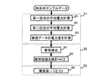
次に、図8と図9を参照して、干渉検出のアルゴリズムについて詳細に説明する。図8は干渉検出アルゴリズムの一例を示し、図9は電力の時系列サンプルデータからパケットの衝突を検出する方法を説明するための図である。図9の縦軸は電力を示し、横軸は時間を示す。 Next, an interference detection algorithm will be described in detail with reference to FIGS. FIG. 8 shows an example of an interference detection algorithm, and FIG. 9 is a diagram for explaining a method of detecting a packet collision from time-series sample data of power. In FIG. 9, the vertical axis indicates power, and the horizontal axis indicates time.
図8に示すように、干渉検出アルゴリズムは、平均電力算出プロセス51と、衝突回数統計プロセス52と、衝突率算出プロセス53とを有する。なお、演算制御部8内のCPU(不図示)が、図8に示す干渉検出アルゴリズムを含むプログラムを実行することで、衝突検出部5が仮想的に構成される。そのため、図8に示す各プロセスを実行する主体が衝突検出部5であるものとして説明する。
As shown in FIG. 8, the interference detection algorithm includes an average
はじめに、平均電力算出プロセス51の動作について詳細に説明する。衝突検出部5は、図9(a)に示す時系列サンプルデータに基づいて、図9(b)に示す第1回目の平均電力計算を行う(ステップB1)。具体的には、衝突検出部5は記憶部3から読み込んだ時系列サンプルデータをN個毎に分け、それぞれの平均電力を求める(ステップB1)。図9(b)に示す例では、N=2である。図9(a)に示す黒丸印は、センシングした信号の電力パワーを示す。
First, the operation of the average
次に、衝突検出部5は、図9(c)に示す第2回目の平均電力計算を行う(ステップB2)。具体的に説明する。衝突検出部5は、ステップB1で求められた平均電力のデータの最初から最後まで順番に調べる。そして、閾値1より大きいデータがあり、その後に、閾値1より大きいデータの連続する数が(M−1)個である場合、衝突検出部5は、これらM個の連続のデータの平均値を求め、求めた平均値をこれらM個のデータのそれぞれの平均電力の値にする。図9(c)に示す例では、M=5である。
Next, the
一方、閾値1より大きいデータがあり、その後に、閾値1より大きいデータの連続する数が(M−1)個より小さい場合、衝突検出部5は、“平均電力が閾値1より大きい最初のデータ”から“平均電力が閾値1より小さい最初のデータの1つ前のデータ(連続する(M−1)個より小さい数のデータのうち、平均電力が閾値1より大きい最後のデータ)”までのデータの平均値を求める。そして、衝突検出部5は、求めた平均値を、平均電力が閾値1より大きい最初のデータから最後のデータまでのそれぞれの平均電力の値とする。
On the other hand, when there is data larger than the
上述のM個のデータ、または(M−1)より小さい個数のデータの場合と同様にして、衝突検出部5は、第2回目の平均電力計算を、それ以降のデータについても、ステップB1で求められた平均電力のデータの最後まで行う。さらに、このようにして求められた平均電力のうち、ノイズの電力閾値より小さい平均電力値をL個(例えば3個)の連続する0値と入れ替える(ステップB2)。図9(c)に示す例では、L=2である。
Similarly to the case of the M data described above or the number of data smaller than (M−1), the
ここで、N×Mは最大伝送速度で送信する1個のテストパケットのサンプル数Kと一致する。NをKの約1%にする場合に適切な計算精度が得られる。閾値1はデバイスの性能によって異なるが、キャリアセンスの閾値より大きく設定する。キャリアセンスの閾値は、CSMA/CAにおいて、チャネルが使用されているか否かを判定するための閾値である。キャリアセンスの閾値はClear Channel Assessmentレベル(CCAレベル)とも言われている。ノイズの電力閾値はノイズの平均電力の1.5倍が適切だと考えられる。ノイズの平均電力は電力測定器により求められる。また、電力判定の基準として、閾値1とは別に閾値2を定義しておく。閾値2はデバイスの性能によって異なるが、閾値1を負の値にしたものと等しい。
Here, N × M matches the number K of samples of one test packet transmitted at the maximum transmission rate. Appropriate calculation accuracy can be obtained when N is about 1% of K. The
衝突検出部5は、図9(c)に例示した、ステップB2で求めた時系列データの全てのデータ値のそれぞれについて、当該データ値から直前のデータ値を引いて、隣接データの電力差を求める(ステップB3)。つまり、隣接する2つのデータについて、時間経過の大きい方から時間経過の小さい方を引いた値を、隣接データの電力差とする。その結果の一例を図9(d)に示す。図9(d)の時間軸の上側は電力差の値がプラスであることを示し、時間軸の下側は電力差の値がマイナスであることを示す。図9(d)における黒三角印は隣接データの電力差を示す。図9(d)を電力差時系列データと称する。
The
次に、衝突回数統計プロセス52の動作について詳細に説明する。
Next, the operation of the collision
衝突検出ステップ(ステップB4)において、衝突検出部5は、ステップB3で求めた時系列データの最初から順番に調べる。閾値1より大きいデータの後に出現する“閾値1より大きいデータ”または“閾値2より小さいデータ”のうち、最初に出現するデータが“閾値1より大きいデータ”である場合(これをケース1と称する)、衝突検出部5は、1回のパケット衝突としてカウントする。ケース1に該当しない場合、次のケースについて判定する。ただし、閾値1をCCAレベルより大きく、かつテスト用パケットの電力の50%より小さく設定する場合があり、このように閾値1を定義した場合、ケース1のパケット衝突は存在しないため、ケース1についての判定を行わない。
In the collision detection step (step B4), the
閾値1より大きいデータの直前のZ個のデータ値の中に0の値が存在しない場合(これをケース2と称する)、あるいは閾値2より小さいデータの直後のY個のデータ値の中に0の値が存在しない場合(これをケース3と称する)、衝突検出部5は、1回のパケット衝突としてカウントする。Zはデバイスの性能によって異なるが、2個が適切だと考えられる。Yはデバイスの性能によって異なるが、5個が適切だと考えられる。ただし、上記のケース2とケース3が連続する場合、つまり、閾値1より大きく、かつ直前のZ個のデータ値の中に0の値が存在しないデータの直後に、閾値2より小さく、かつ直後のY個のデータ値の中に0の値が存在しないデータ値が出現する場合、衝突検出部5は、2回のパケット衝突とカウントせず、1回のパケット衝突としてカウントする。
If there is no 0 value in the Z data values immediately before the data greater than the threshold 1 (this is referred to as case 2), or 0 in the Y data values immediately after the data smaller than the
一方、“閾値1より大きいデータ(このデータを「データP1」と称する)”の直前のZ個のデータの中に0が存在し、データP1の後に最初に出現する“閾値2より小さいデータ(このデータを「データP2」と称する)”の直後のY個のデータの中に0が存在する場合、衝突検出部5は、次に説明するケース4またはケース5のいずれかに該当すると判定すると、1回のパケット衝突としてカウントする。ケース4は、データP2の後に出現する“閾値1より大きいデータ”または“閾値2より小さいデータ”のうち、最初に出現するデータが“閾値2より小さいデータ”の場合である。ケース5は、データP2の後に出現する“閾値1より大きいデータ”または“閾値2より小さいデータ”のうち、最初に出現するデータが“閾値1より大きいデータ”であり、かつ、データP1とデータP2の和の絶対値が閾値3より大きい場合である。閾値3はデバイスの性能によって異なるが、閾値1と同等の値が適切だと考えられる。ケース4およびケース5のいずれにも該当しなければ、衝突検出部5は、パケット衝突ではないと判定する。衝突検出部5は、上述のようにしてカウントしたパケット衝突の回数C2を記録装置3に保存する(ステップB5)。
On the other hand, 0 exists in the Z data immediately before “data larger than threshold 1 (this data is referred to as“ data P1 ”)”, and data “smaller than threshold 2 (first appearing after data P1) ( When 0 is present in Y data immediately after “this data is referred to as“ data P2 ”), the
ここで、図9(d)を参照して、衝突検出部5がケース4のパケット衝突を検出する方法を説明する。図9(d)には、説明のために、隣接データの電力差を示すデータに符号101〜108を付している。
Here, with reference to FIG. 9D, a method in which the
図9(d)に示すデータ101はデータP1の条件に当てはまり、データ102はデータP2の条件に当てはまるが、データ102の後に、閾値2より小さいデータではなく、閾値1より大きいデータ103が最初に出現するので、ケース4には該当しない。また、データ102の後に閾値1より大きいデータ103が最初に出現するが、データ101とデータ102の和の絶対値はほぼ0(<閾値3)となり、ケース5にも該当しない。
The
続いて、図9(d)を参照して、時間軸に沿ってデータを見ていくと、データ103がデータP1の条件に当てはまり、データ104がデータP2の条件に当てはまるので、ケース4またはケース5に該当するか検討する。図9(d)を見ると、データ104の後に、閾値1より大きいデータではなく、閾値2より小さいデータ106が最初に出現するので、ケース4に該当することがわかる。なお、データ104の後のデータ105は、閾値1より小さく、かつ閾値2より大きいので、“閾値1より大きいデータ”または“閾値2より小さいデータ”のいずれにも該当せず、判定対象から除外される。
Subsequently, referring to FIG. 9 (d), when the data is viewed along the time axis, the
さらに、図9(d)を参照して、時間軸に沿ってデータを見ていくと、データ107がデータP1の条件に当てはまり、データ108がデータP2の条件に当てはまる。しかし、図9に例示する時系列データの観測時間の範囲では、データ108の後には、“閾値1より大きいデータ”または“閾値2より小さいデータ”が出現していないので、パケット衝突があるか否かを判定する必要はない。
Furthermore, referring to FIG. 9D, when the data is viewed along the time axis, the data 107 applies to the condition of the data P1, and the
ここで、閾値1をキャリアセンスの閾値より大きく設定する理由を説明する。図10は想定される2種類のパケット衝突パターンを説明するための模式図である。図10の縦軸は電力を示し、横軸は時間を示す。そして、図10では、送信端末の送信パケットの電力を縦長の四角形で示し、干渉パケットの電力を横長の四角形で示している。
Here, the reason why the
パケットの衝突には2種類のパターンがある。この2種類のパターンを第1および第2のパターンと称する。図10(a)は第1のパターンの時系列サンプルデータを模式的に示す図であり、図10(b)は図10(a)に示した時系列サンプルデータに対して包絡特徴抽出を行った電力差時系列データを模式的に示す図である。ただし、図10(b)では、閾値1より電力の低い干渉パケットの部分が「0でない値が連続して出現すること」を示すために、図10(a)に示した干渉パケットをそのまま模式的に示している。
There are two types of packet collisions. These two types of patterns are referred to as a first pattern and a second pattern. FIG. 10A is a diagram schematically showing time-series sample data of the first pattern, and FIG. 10B is an envelope feature extraction performed on the time-series sample data shown in FIG. It is a figure which shows typically the electric power difference time series data. However, in FIG. 10B, in order to indicate that the portion of the interference packet whose power is lower than the
図10(a)に示す第1のパターンは、干渉パケットの電力がキャリアセンスの閾値より大きい場合である。この場合、各送信端末が互いの送信パケットの存在を正しく検知できる。各送信端末はチャネルが空いていると判定した後、ちょうど同時にパケットを送信すると、図10(a)に示すように、パケットの衝突が起こり得る。図10(a)に示すパケット衝突pc1は、図10(b)を見てわかるように、上述したパケット衝突検出判定のケース5に相当する。また、図10(a)に示すパケット衝突pc2は、上述したパケット衝突検出判定のケース3に相当する。
The first pattern shown in FIG. 10A is a case where the power of the interference packet is larger than the carrier sense threshold. In this case, each transmitting terminal can correctly detect the presence of each other's transmission packet. If each transmitting terminal determines that the channel is free and then transmits a packet at the same time, a packet collision may occur as shown in FIG. The packet collision pc1 shown in FIG. 10A corresponds to the
ここで、図10(b)では、パケット衝突pc3は検出されないように見える。これは、図10(a)に示す観測時間では、パケット衝突pc3の後に出現するテスト用パケットが観測されていないからである。パケット衝突pc3の後にテスト用パケットが検出されると、パケット衝突pc3における「閾値1より大きいデータ」の後に出現する“閾値1より大きいデータ”または“閾値2より小さいデータ”のうち、最初に出現するデータは、次のテスト用パケットの「閾値1より大きいデータ」となる。そのため、パケット衝突pc3は、上述したパケット衝突検出判定のケース1に相当する。よって、本実施形態では、第1のパターンのパケット衝突を検出できることがわかる。
Here, in FIG. 10B, it seems that the packet collision pc3 is not detected. This is because the test packet that appears after the packet collision pc3 is not observed in the observation time shown in FIG. When a test packet is detected after packet collision pc3, the first occurrence of “data greater than
図10(c)は第2のパターンの時系列サンプルデータを模式的に示す図であり、図10(d)は図10(c)に示した時系列サンプルデータに対して包絡特徴抽出を行った電力差時系列データを模式的に示す図である。ただし、図10(d)では、キャリアセンスの閾値より電力の低い干渉パケットの部分が「0でない値が連続して出現すること」を示すために、図10(c)に示した干渉パケットをそのまま模式的に示している。 FIG. 10C is a diagram schematically showing the time-series sample data of the second pattern, and FIG. 10D is an envelope feature extraction performed on the time-series sample data shown in FIG. It is a figure which shows typically the electric power difference time series data. However, in FIG. 10D, in order to indicate that the part of the interference packet whose power is lower than the threshold value of the carrier sense indicates that “a non-zero value appears continuously”, the interference packet shown in FIG. It is shown schematically as it is.
図10(c)に示す第2のパターンは、干渉パケットの電力がキャリアセンスの閾値より小さい場合である。この場合、各送信端末が互いの送信パケットの存在を正しく検知できないため、チャネルのビジー状態を正しく判定できない。その結果、図10(c)に示すように、自端末が送出したパケットと、検出できない干渉パケットとの衝突が発生する。図10(c)に示す3つのパケット衝突は、図10(d)を見てわかるように、上述したパケット衝突検出判定のケース2またはケース3に相当している。そのため、本実施形態では、第2のパターンのパケット衝突も検出できることがわかる。
The second pattern shown in FIG. 10C is a case where the power of the interference packet is smaller than the carrier sense threshold. In this case, since each transmitting terminal cannot correctly detect the presence of each other's transmission packet, the busy state of the channel cannot be determined correctly. As a result, as shown in FIG. 10C, a collision between a packet transmitted by the terminal itself and an interference packet that cannot be detected occurs. The three packet collisions shown in FIG. 10 (c) correspond to the above-described
図10を参照して説明したように、本実施形態では、閾値1をキャリアセンスの閾値より大きく設定することで、上記の第1および第2のパターンのいずれの衝突パターンの検出にも対応できることがわかる。
As described with reference to FIG. 10, in the present embodiment, by setting the
次に、衝突率算出プロセス53の動作について詳細に説明する。衝突検出部5は、衝突率を算出するため、本実施形態の無線通信機が送信したテスト用パケットの個数C1とパケット衝突の回数C2を記憶部3から読み出し、以下に示す式(2)によって衝突率を求める。最後に、衝突検出部5は、算出した衝突率を記憶部3に保存する(ステップB6)。
Next, the operation of the collision
![]()
![]()
式(2)において、右辺の分母は送信したテスト用パケットの個数C1であり、分子はパケット衝突の回数C2である。 In Expression (2), the denominator on the right side is the number C1 of test packets transmitted, and the numerator is the number of packet collisions C2.
次に、図4に示した実験を用いて、衝突検出の実験結果を示す。ここでも、無線機Aが本実施形態の無線通信機とし、無線機B、無線機Cおよび無線機DがIEEE802.11を満たす無線通信機とする。 Next, an experimental result of collision detection will be shown using the experiment shown in FIG. Again, the wireless device A is the wireless communication device of the present embodiment, and the wireless device B, the wireless device C, and the wireless device D are wireless communication devices that satisfy IEEE 802.11.
図4に示すように、例えば、無線機Aが自機から9メートル離れた無線機Bにパケットを無線送信するものとする。同時に、無線機Cが自機から9メートル離れた無線機Dにパケットを無線送信するものとする。無線機Aから無線機Bへのパケット送信をflow1と呼び、無線機Cから無線機Dへのパケット送信をflow2と呼ぶ。flow2がflow1に与える干渉信号を検出対象とする。従って、flow2をflow1から離していくにつれ、flow2がflow1に与える干渉が弱まる。 As shown in FIG. 4, for example, it is assumed that the wireless device A wirelessly transmits a packet to the wireless device B which is 9 meters away from the own device. At the same time, the wireless device C wirelessly transmits a packet to the wireless device D that is 9 meters away from the wireless device C. Packet transmission from the wireless device A to the wireless device B is called flow1, and packet transmission from the wireless device C to the wireless device D is called flow2. An interference signal that flow2 gives to flow1 is a detection target. Therefore, as flow2 is moved away from flow1, the interference that flow2 gives to flow1 is weakened.
図4に示す例では、flow1に与える干渉波の強度を調査するために、flow2をflow1から離す距離を、1メートル、10メートル、40メートル、80メートル、110メートル、および200メートルの6つの場合とし、それぞれの距離の位置にflow2を順番に移動させる。各位置で、無線機Aが54Mpbsの伝送レートで固定長さ1500バイトのテスト用パケットを0dBmの送信電力で無線機Bに3秒間送信する。同時に無線機Cが6Mpbsの伝送レートで固定長さ1500バイトのテスト用パケットを0dBmの送信電力で3秒間送信する。ここでは、flow2がflow1に与える干渉を、限られた移動距離(200メートル)内に減衰させるため、最大送信電力ではなく0dBmの送信電力でテスト送信を行う。
In the example shown in FIG. 4, in order to investigate the intensity of the interference wave applied to flow1, the distances where flow2 is separated from flow1 are six cases of 1 meter, 10 meters, 40 meters, 80 meters, 110 meters, and 200 meters. Then, the
閾値1をテスト用パケットの平均電力の35%に設定する。つまり、テスト用パケットの平均電力の絶対値をPとすると、閾値1=(P×0.35)となる。閾値2をテスト用パケットの平均電力の35%の負の値に設定する。つまり、テスト用パケットの平均電力の絶対値をPとすると、閾値2=−(P×0.35)となる。閾値3をテスト用パケットの平均電力の35%に設定する。つまり、テスト用パケットの平均電力の絶対値をPとすると、閾値3=(P×0.35)となる。各位置でのテスト用パケット送信期間内の衝突検出結果を表2に示す。
The
表2には、flow1およびflow2間の距離に対応して、送信パケット数、パケット衝突数およびパケット衝突率が記述されている。 Table 2 describes the number of transmitted packets, the number of packet collisions, and the packet collision rate corresponding to the distance between flow1 and flow2.
本実施形態の無線通信機の通信状態分類部4の分類結果と衝突検出部5の衝突検出結果をそれぞれ用いて、無線通信機の通信を制御する動作について詳細に説明する。
The operation for controlling the communication of the wireless communication device will be described in detail using the classification result of the communication
はじめに、本実施形態の無線通信機の通信状態分類部4の分類結果に基づく、制御部6の通信制御方法について詳細に説明する。本実施形態の無線通信機の制御部6は、記憶部3に対して定期的にチェックを行い、通信状態の更新の有無を確認する。通信状態の更新が確認された場合、制御部6は、通信部1に動作指令を出す。表3に制御部6から通信部1に送出される動作指令の一例を示す。
First, the communication control method of the
表3には、通信状態がPAの場合とGrayの場合の動作指令が記述されている。チャネル、パケットサイズおよび通信ルートのそれぞれは、送信パラメータの一種である。 Table 3 describes operation commands when the communication state is PA and Gray. Each of the channel, the packet size, and the communication route is a kind of transmission parameter.
表3に示すように、動作指令には、動作指令1、動作指令2および動作指令3がある。本実施形態では、動作指令に優先度を設けており、動作指令1が動作指令2より優先度が高く、動作指令2が動作指令3より優先度が高い。本実施形態の無線通信機は動作指令1のチャネル変更指令を実行することにより、他の干渉信号が存在しないチャネル、あるいは、他の干渉信号からの影響が少ないチャネルで送信することが可能となる。通信状態がPAの場合、本実施形態の無線通信機は動作指令2のパケットサイズ増加指令を実行することにより、1回の送信でより多いデータを送信でき、より多い時間でチャネルを利用でき、伝送効率を上げられる。通信状態がGrayの場合、本実施形態の無線通信機は動作指令2のパケットサイズ減少指令を実行することにより、1つのデータパッケトの伝送にチャネルの利用時間が減少し、他の干渉信号との衝突の確率が下がり、伝送効率を上げられる。本実施形態の無線通信機は動作指令3の通信ルート変更指令を実行することにより、他の干渉信号が存在しない通信ルート、あるいは、他の干渉信号からの影響が少ない通信ルートで送信することが可能となる。
As shown in Table 3, the operation commands include an
図11を参照して、本実施形態の無線通信機の通信状態が更新された場合、かつ通信状態が1つしか確認されない場合の通信制御動作について詳細に説明する。 With reference to FIG. 11, the communication control operation when the communication state of the wireless communication device of the present embodiment is updated and when only one communication state is confirmed will be described in detail.
はじめに、制御部6が、通信状態がPAに更新されたのを確認した場合を説明する。制御部6は通信状態がPAに更新されたのを確認した場合、まず、動作指令1の「通信チャネル変更指令」をデータ送受信部12に送る。データ送受信部12が制御部6からの指令(動作指令1)を受けた後、素早く指令(動作指令1)に従って動作を実行する。データ送受信部12が制御部6からの指令に従って動作実行できない場合、制御部6に指令実行失敗の信号を送る。
First, a case where the
制御部6は、データ送受信部12からの指令実行失敗の信号を受け取った場合、データ送受信部12に送った前回の指令よりも優先度が1つ低い動作指令2の「パケットサイズ増加指令」をデータ送受信部12に送る。データ送受信部12が制御部6からの指令(動作指令2)を受けた後、素早く指令に従って動作を実行する。データ送受信部12が制御部6からの指令(動作指令2)に従って動作実行できない場合、制御部6に指令実行失敗の信号を送る。
When the
制御部6は、データ送受信部12からの指令実行失敗の信号を受け取った場合、データ送受信部12に送った前回の指令よりも優先度が1つ低い動作指令3の「通信ルート変更指令」をデータ送受信部12に送る。データ送受信部12が制御部6からの指令(動作指令3)を受けた後、素早く指令に従って動作を実行する。データ送受信部12が制御部6からの指令(動作指令3)に従って動作実行できない場合、制御部6に指令実行失敗の信号を送る。
When the
制御部6は、データ送受信部12からの指令実行失敗の信号を受け取った場合、かつデータ送受信部12に送った前回の指令よりも優先度の低い動作指令が存在しない場合、次の通信状態の更新を確認するまで動作指令を送信しない。
When the
続いて、制御部6が、通信状態がGrayに更新されたのを確認した場合を説明する。制御部6は通信状態がGrayに更新されたのを確認した場合、まず、動作指令1の「通信チャネル変更指令」をデータ送受信部12に送る。データ送受信部12が制御部6からの指令(動作指令1)を受けた後、素早く指令(動作指令1)に従って動作を実行する。データ送受信部12が制御部6からの指令に従って動作実行できない場合、制御部6に指令実行失敗の信号を送る。
Subsequently, a case where the
制御部6は、データ送受信部12からの指令実行失敗の信号を受け取った場合、データ送受信部12に送った前回の指令よりも優先度が1つ低い動作指令2の「パケットサイズ減少指令」をデータ送受信部12に送る。データ送受信部12が制御部6からの指令(動作指令2)を受けた後、素早く指令に従って動作を実行する。データ送受信部12が制御部6からの指令(動作指令2)に従って動作実行できない場合、制御部6に指令実行失敗の信号を送る。
When the
制御部6は、データ送受信部12からの指令実行失敗の信号を受け取った場合、データ送受信部12に送った前回の指令よりも優先度が1つ低い動作指令3の「通信ルート変更指令」をデータ送受信部12に送る。データ送受信部12が制御部6からの指令(動作指令3)を受けた後、素早く指令に従って動作を実行する。データ送受信部12が制御部6からの指令(動作指令3)に従って動作実行できない場合、制御部6に指令実行失敗の信号を送る。
When the
制御部6は、データ送受信部12からの指令実行失敗の信号を受け取った場合、かつデータ送受信部12に送った前回の指令より優先度の低い動作指令が存在しない場合、次の通信状態の更新を確認するまで動作指令を送信しない。
When receiving a command execution failure signal from the data transmitter /
図12を参照して、本実施形態の無線通信機の通信状態が更新された場合、かつ2つの通信状態が確認される場合の通信制御動作について詳細に説明する。 With reference to FIG. 12, the communication control operation when the communication state of the wireless communication device of the present embodiment is updated and when two communication states are confirmed will be described in detail.
干渉源が2つ以上に存在するため、通信状態のPAとGrayが同時に存在することがある。制御部6はPAとGrayの2つの通信状態が同時に存在し、かつ通信状態が更新されたのを確認した場合、まず、動作指令1の「通信チャネル変更指令」をデータ送受信部12に送る。データ送受信部12が制御部6からの指令(動作指令1)を受けた後、素早く指令(動作指令1)に従って動作を実行する。データ送受信部12が制御部6からの指令に従って動作実行できない場合、制御部6に指令実行失敗の信号を送る。
Since there are two or more interference sources, the communication state PA and Gray may exist simultaneously. When it is confirmed that the two communication states of PA and Gray exist at the same time and the communication state is updated, the
制御部6は、データ送受信部12からの指令実行失敗の信号を受け取った場合、データ送受信部12に送った前回の指令よりも優先度の低い動作指令3の「通信ルート変更指令」をデータ送受信部12に送る。データ送受信部12が制御部6からの指令(動作指令3)を受けた後、素早く指令に従って動作を実行する。データ送受信部12が制御部6からの指令(動作指令3)に従って動作実行できない場合、制御部6に指令実行失敗の信号を送る。
When receiving a command execution failure signal from the data transmitting / receiving
制御部6がデータ送受信部12からの指令実行失敗の信号を受け取った場合、かつデータ送受信部12に送った前回の指令より優先度の低い動作指令が存在しない場合、次の通信状態の更新を確認するまで動作指令を送信しない。制御部6は通信状態がGoodに更新されたのを確認した場合、次の通信状態の更新を確認するまで動作指令を発送しない。
When the
次に、本実施形態の無線通信機の衝突検出部5の衝突検出結果に基づく、制御部6の通信制御方法について詳細に説明する。
Next, the communication control method of the
本実施形態の無線通信機の制御部6は、記憶部3に定期的にチェックを行い、衝突率の更新を確認する。制御部6は、衝突率の更新を確認した場合、かつ衝突率が閾値4より大きい場合、送信パラメータの調整を指示する旨の送信パラメータ調整指令をデータ送受信部12に送る。データ送受信部12は、制御部6から送信パラメータ調整指令を受け取ると、素早く指令に従って送信パラメータを調整する。送信パラメータには、キャリアセンス感度、バックオフ時間および伝送レートなどがある。バックオフ時間は、802.11無線機の送信待機時間のことである。閾値4はデバイスの性能と通信の応用によって決められる。例えば、図4に示す実験の場合、表2に示す衝突検出結果を参照し、閾値4を80%としている。
The
なお、衝突率が閾値4より大きい場合、例えば、送信パラメータがキャリアセンス感度である場合、送信パラメータの調整はキャリアセンス感度を高くすることであり、送信パラメータが送信パケットサイズである場合、送信パラメータの調整は送信パケットサイズを下げることであり、送信パラメータが伝送レートである場合、送信パラメータの調整は伝送レートを上げることである。これらの送信パラメータのうち、いずれを調整対象として選択するか、また、選択した送信パラメータをどのように調整するかは、パケットの衝突を回避するだけでなく、通信環境が全体的に改善されるように、最適な条件に設定するのが望ましい。
When the collision rate is larger than the
本実施形態の無線通信機では、データ送信が他の通信からの干渉を受ける場合、自機の通信状態が3つの通信状態のうち、いずれの通信状態であるかを判定し、判定した通信状態に基づいて送信パラメータを調整することによって伝送効率を高めることができる。 In the wireless communication device of this embodiment, when data transmission receives interference from other communication, the communication state of the own device is determined from among the three communication states, and the determined communication state The transmission efficiency can be increased by adjusting the transmission parameter based on the above.
また、本実施形態の無線通信機では、データ送信を開始する前に、周囲電波状況におけるテスト用パケットの衝突の発生を予め検出し、衝突が発生する場合の衝突率を計算し、衝突検出の結果と衝突率に基づいて、送信パラメータを適切に調整している。そのため、他の通信からの干渉の検出精度を高めることができ、他の通信との干渉を防ぎ、伝送効率を高めることができる。 In addition, in the wireless communication device according to the present embodiment, before starting data transmission, the occurrence of a test packet collision in the surrounding radio wave condition is detected in advance, the collision rate when the collision occurs is calculated, and the collision detection is performed. Based on the result and collision rate, the transmission parameters are adjusted appropriately. Therefore, the detection accuracy of interference from other communications can be increased, interference with other communications can be prevented, and transmission efficiency can be increased.
(第2の実施形態)
本実施形態の無線通信機を、図面を参照して説明する。なお、第1の実施形態と同様な構成については、その詳細な説明を省略する。
(Second Embodiment)
A wireless communication device of this embodiment will be described with reference to the drawings. Note that detailed description of configurations similar to those of the first embodiment is omitted.
図13は本実施形態の無線通信機の一構成例を示すブロック図である。図13に示すように、本実施形態の無線通信機は、通信部1と、計算処理部2と、記憶部3と、通信状態分類部4と、制御部6とを有する構成である。本実施形態では、通信部1に、データ送信部12が設けられているが、図1に示した信号センシング部11が設けられていない。
FIG. 13 is a block diagram illustrating a configuration example of the wireless communication device according to the present embodiment. As shown in FIG. 13, the wireless communication device of this embodiment has a configuration including a
本実施形態の無線通信機は、図1に示した信号センシング部11と衝突検出部5を有していない。したがって、本実施形態では、伝送効率を高めるための送信パラメータの調整は通信状態分類部4から出力される結果に基づいて行われる。
The wireless communication device of the present embodiment does not have the
本実施形態では、図1に示した衝突検出部5から出力される衝突率による送信パラメータの調整を行わなくても、あるいは、衝突検出部5による衝突検出を行わなくても、伝送効率を高めることができるだけでなく、無線通信機の回路構成が簡単になり、消費電力を抑えられる利点がある。
In this embodiment, transmission efficiency is improved without adjusting transmission parameters based on the collision rate output from the
(第3の実施形態)
本実施形態の無線通信機を、図面を参照して説明する。なお、第1の実施形態と同様な構成については、その詳細な説明を省略する。
(Third embodiment)
A wireless communication device of this embodiment will be described with reference to the drawings. Note that detailed description of configurations similar to those of the first embodiment is omitted.
図14は本実施形態の無線通信機の一構成例を示すブロック図である。図14に示すように、本実施形態の無線通信機は、通信部1と、計算処理部2と、記憶部3と、衝突検出部5と、制御部6とを有する構成である。
FIG. 14 is a block diagram illustrating a configuration example of the wireless communication device according to the present embodiment. As shown in FIG. 14, the wireless communication device of the present embodiment has a configuration including a
本実施形態の無線通信機は、図1に示した通信状態分類部4を有していない。したがって、本実施形態では、伝送効率を高めるための送信パラメータの調整は衝突検出部5から出力される結果に基づいて行われる。
The wireless communication device of the present embodiment does not have the communication
本実施形態では、図1に示した通信状態分類部4から出力される通信状態による送信パラメータの調整を行わなくても、伝送効率を高めることができるだけでなく、無線通信機の回路構成が簡単になり、消費電力を抑えられる利点がある。
In this embodiment, it is possible not only to improve the transmission efficiency but also to simplify the circuit configuration of the wireless communication device without adjusting the transmission parameter according to the communication state output from the communication
(第4の実施形態)
本発明の無線通信機を、メッシュネットワークを構成する基地局に適用することが可能である。本実施形態では、第1の実施形態の無線通信機をメッシュネットワークの基地局として動作させる場合のメッシュネットワークの構成について説明する。
(Fourth embodiment)
The wireless communication device of the present invention can be applied to base stations constituting a mesh network. In the present embodiment, a configuration of a mesh network when the wireless communication apparatus of the first embodiment is operated as a base station of the mesh network will be described.
図15は、第1の実施形態の無線通信機が基地局として構成されるメッシュネットワークの一例を示す図である。図15に示す丸印が基地局に相当する。基地局の位置設定は実際の応用に応じて、一般的なメッシュネットワークの基地局の設置方法に従って行われる。複数の基地局のうち、1つの基地局がネットワーク内通信を管理するネットワーク通信管理部として機能する。以下では、このネットワーク通信管理部を管理局と称する。図15では、管理局を符号7で表している。 FIG. 15 is a diagram illustrating an example of a mesh network in which the wireless communication device according to the first embodiment is configured as a base station. A circle shown in FIG. 15 corresponds to a base station. The position setting of the base station is performed in accordance with a general mesh network base station installation method according to the actual application. Of the plurality of base stations, one base station functions as a network communication management unit that manages intra-network communication. Hereinafter, this network communication management unit is referred to as a management station. In FIG. 15, the management station is denoted by reference numeral 7.
次に、本実施形態のメッシュネットワークの初期設定と運用方法について詳細に説明する。 Next, the initial setting and operation method of the mesh network of this embodiment will be described in detail.
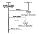
メッシュネットワークの初期設定は、基地局のキャリアセンス感度の調整と通信路の通信品質測定との2段階で構成される。まず、メッシュネットワーク内の基地局のキャリアセンス感度の調整について、図16を参照して詳細に説明する。 The initial setting of the mesh network is composed of two stages: adjustment of carrier sense sensitivity of the base station and measurement of communication quality of the communication path. First, adjustment of carrier sense sensitivity of a base station in a mesh network will be described in detail with reference to FIG.
メッシュネットワーク内の基地局の位置設定が完了した後、ネットワーク内通信を管理する1つの基地局が管理局7として選出される。管理局7はネットワーク内に最小あるいは最大MACアドレスを持つ基地局から自動的に選出される。管理局7の安定性を考えると、管理局7として、電源給電の基地局、無停電電源装置を装備する基地局、イーサネット(登録商標)に接続する基地局などの基地局から優先的に選出すべきである。選出された管理局7は自分のアドレスをネットワーク内の全ての基地局に送信する。各基地局は受信した管理局7のアドレスを自分の記憶部3に保存する。管理局7が変更された場合、新しい管理局7が自分のアドレスをネットワーク内の全ての基地局に送信し、各基地局が記憶部3に保存している管理局7のアドレスを更新する。ここでは、管理局の選出方法として、いくつかの例を示したが、ここで説明した方法に限定するものではない。
After the position setting of the base station in the mesh network is completed, one base station that manages the intra-network communication is selected as the management station 7. The management station 7 is automatically selected from the base stations having the minimum or maximum MAC address in the network. Considering the stability of the management station 7, the management station 7 is preferentially selected from base stations such as a power supply base station, a base station equipped with an uninterruptible power supply, and a base station connected to the Ethernet (registered trademark). Should be issued. The selected management station 7 transmits its own address to all base stations in the network. Each base station stores the received address of the management station 7 in its
次に、管理局7はネットワーク内の任意の1つの基地局に指令を送り、当該基地局に衝突検出するための一定の伝送速度(例えば6Mbps)かつ最大電力でのテスト送信(ブロードキャスト送信)をさせる(ステップD1)。図15では、テスト送信を行う基地局を、基地局K1としている。ブロードキャスト送信を送信TAと称する。この時点で、基地局K1以外の基地局がアイドル状態である。 Next, the management station 7 sends a command to any one base station in the network, and performs a test transmission (broadcast transmission) at a constant transmission rate (for example, 6 Mbps) and maximum power for detecting a collision with the base station. (Step D1). In FIG. 15, the base station that performs the test transmission is the base station K1. Broadcast transmission is referred to as transmission TA. At this point, base stations other than the base station K1 are in an idle state.
次に、アイドル状態である基地局の中の任意の1つの基地局に、管理局7が指令を送り、基地局K1と同じチャネルかつフルレート(ここでは、「フルレート」は休まずに連続的に動作することを意味する)でテスト送信(ブロードキャスト送信)をさせる(ステップD2)。ここで、テスト送信を行う基地局を、基地局K2とする。このときのブロードキャスト送信を送信TBと称する。基地局K2のテスト送信速度は基地局K1の伝送速度より高くする(例えば54Mbps)。 Next, the management station 7 sends a command to any one of the base stations that are in the idle state, and the same channel and full rate as the base station K1 (here, “full rate” is continuously without a pause). Test transmission (broadcast transmission) (step D2). Here, the base station that performs the test transmission is assumed to be a base station K2. The broadcast transmission at this time is referred to as transmission TB. The test transmission rate of the base station K2 is set higher than the transmission rate of the base station K1 (for example, 54 Mbps).
次に、基地局K2がテスト送信開始後、管理局7は基地局K2に指令を送り、基地局K2に基地局K1のテスト送信との衝突検出を実行させる(ステップD3)。基地局K2は衝突検出後に基地局K1のテスト送信との衝突率を基地局K2の記憶部3に保存する(ステップD4)。
Next, after the base station K2 starts test transmission, the management station 7 sends a command to the base station K2, causing the base station K2 to detect collision with the test transmission of the base station K1 (step D3). After the collision is detected, the base station K2 stores the collision rate with the test transmission of the base station K1 in the
次に、管理局7は基地局K2に指令を送り、基地局K2のテスト送信を停止させ、基地局K2をアイドル状態に戻す(ステップD5)。基地局K2は記憶部3に保存する衝突率を閾値4と比較し(ステップD6)、衝突率が閾値4より大きい場合、基地局K1への干渉を抑制するようにキャリアセンスの感度を調整する(ステップD7)。
Next, the management station 7 sends a command to the base station K2, stops the test transmission of the base station K2, and returns the base station K2 to the idle state (step D5). The base station K2 compares the collision rate stored in the
次に、管理局7は送信TAあるいは送信TBを行った基地局以外の任意の基地局に順次に指令を送り、それぞれの基地局にステップD2からステップD7までの動作を実行させる(ステップD8)。ステップD2からステップD8までの動作により基地局K1とネットワーク内の他の基地局と同時に通信する場合の互いの干渉が抑えられる。次に、管理局7は基地局K1に指令を送り、基地局K1のテスト送信を停止させ、基地局K1をアイドル状態に戻す(ステップD9)。 Next, the management station 7 sequentially sends an instruction to any base station other than the base station that has performed transmission TA or transmission TB, and causes each base station to execute the operations from Step D2 to Step D7 (Step D8). . By the operations from Step D2 to Step D8, mutual interference when communicating simultaneously with the base station K1 and other base stations in the network is suppressed. Next, the management station 7 sends a command to the base station K1, stops the test transmission of the base station K1, and returns the base station K1 to the idle state (step D9).
次に、管理局7は送信TAを行った基地局以外の任意の基地局に順次に指令を送り、それぞれの基地局にステップ1からステップ7までの動作を実行させる(ステップD10)。ステップD1からステップD10までの動作によりネットワーク内の全ての基地局の互いの干渉が抑えられる。
Next, the management station 7 sequentially sends instructions to any base station other than the base station that has performed the transmission TA, and causes each base station to execute the operations from
次に、メッシュネットワーク内の通信路の通信品質測定について、図17を参照して詳細に説明する。 Next, communication quality measurement of communication paths in the mesh network will be described in detail with reference to FIG.
まず、管理局7はネットワーク内の任意の1つ基地局H1に指令を送り、基地局H1に基地局H1の隣接の任意の1つの基地局H2にテスト送信を実行させる(ステップE1)。このテスト送信を送信FAと称する。基地局H1は固定の伝送速度かつフルレートで基地局H2にテスト送信を行う。この時点で、基地局H1および基地局H2を除く基地局がアイドル状態である。次に、管理局7は、基地局H1および基地局H2を除く任意の1つの基地局H3に指令を送り、基地局H3に基地局H3の隣接の任意の1つの基地局H4にテスト送信(ユニキャスト送信)を実行させる(ステップE2)。このテスト送信を送信FBと称する。基地局H3は固定の伝送速度かつフルレートで基地局H4にテスト送信を行う。 First, the management station 7 sends a command to any one base station H1 in the network, and causes the base station H1 to perform test transmission to any one base station H2 adjacent to the base station H1 (step E1). This test transmission is referred to as a transmission FA. The base station H1 performs test transmission to the base station H2 at a fixed transmission speed and full rate. At this point, the base stations other than the base station H1 and the base station H2 are idle. Next, the management station 7 sends a command to any one base station H3 except the base station H1 and the base station H2, and sends a test transmission to the base station H3 to any one base station H4 adjacent to the base station H3 ( Unicast transmission) is executed (step E2). This test transmission is referred to as transmission FB. The base station H3 performs test transmission to the base station H4 at a fixed transmission speed and full rate.
次に、管理局7は基地局H1に指令を送り、基地局H1に送信FAの通信状態を分類させる(ステップE3)。上記の通信状態の分類が完了した後に、基地局H1は、送信FBが存在する場合の送信FAの通信状態の分類結果と、送信FAの伝送速度と、送信FBの伝送速度とを管理局7に送る(ステップE4)。管理局7は、送信FBが存在する場合の送信FAの通信状態の分類結果、送信FAの伝送速度、および送信FBの伝送速度の情報を基地局H1から受け取ると、これらの情報を1つの組にして記憶部3に保存する。
Next, the management station 7 sends a command to the base station H1, and causes the base station H1 to classify the communication state of the transmission FA (step E3). After the above communication state classification is completed, the base station H1 determines the result of classification of the communication state of the transmission FA, the transmission rate of the transmission FA, and the transmission rate of the transmission FB when the transmission FB exists. (Step E4). When the management station 7 receives from the base station H1 information on the classification result of the communication state of the transmission FA when the transmission FB exists, the transmission speed of the transmission FA, and the transmission speed of the transmission FB from the base station H1, the management station 7 And stored in the
次に、管理局7は基地局H3が全ての伝送速度で送信FBを実行したかを判断し(ステップE5)、基地局H3が全ての伝送速度での送信FBを終了していない場合、基地局H3に指令を送り、基地局H3にテスト送信の伝送速度を予め決められた範囲内で変更させ(ステップE6)、ステップE2の処理に戻る。なお、ここで言う「全ての伝送速度」とは、予め決められた範囲の伝送レートであり、例えば、表1に示す伝送レートである。 Next, the management station 7 determines whether the base station H3 has executed transmission FB at all transmission rates (step E5). If the base station H3 has not completed transmission FB at all transmission rates, A command is sent to the station H3, the transmission rate of the test transmission is changed within a predetermined range to the base station H3 (step E6), and the process returns to step E2. The “all transmission speeds” mentioned here are transmission rates within a predetermined range, for example, the transmission rates shown in Table 1.
次に、基地局H3が全ての伝送速度で送信FBを実行した場合(ステップE5)、管理局7は基地局H1が全ての伝送速度で送信FAを実行したかを判断し(ステップE7)、基地局H1が全ての伝送速度での送信FAを終了していない場合、管理局7は基地局H1に指令を送り、基地局H1にテスト送信の伝送速度を予め決められた範囲内で変更させ(ステップE8)、ステップE1の処理に戻る。 Next, when the base station H3 executes transmission FB at all transmission rates (step E5), the management station 7 determines whether the base station H1 executes transmission FA at all transmission rates (step E7). If the base station H1 has not finished transmission FA at all transmission rates, the management station 7 sends a command to the base station H1, causing the base station H1 to change the transmission rate of the test transmission within a predetermined range. (Step E8), the process returns to Step E1.
次に、基地局H1が全ての伝送速度での送信FAを終了した場合(ステップE7)、管理局7は基地局H3と基地局H4に指令を送り、基地局H3のテスト送信を停止させ、基地局H3および基地局H4をアイドル状態に戻す(ステップE9)。 Next, when the base station H1 ends the transmission FA at all transmission speeds (step E7), the management station 7 sends a command to the base station H3 and the base station H4 to stop the test transmission of the base station H3, The base station H3 and the base station H4 are returned to the idle state (step E9).
管理局7は、ステップE1で基地局H1に送信FAを実行させているときに、送信FBを実行していない基地局の有無を判断する(ステップE10)。ステップE10で、送信FBを実行していない基地局が存在する場合、管理局7は、送信FBを実行していない基地局H3(送信側)と基地局H4(受信側)を選出し(ステップE11)、基地局H3と基地局H4に指令を送り、ステップE2の処理に戻る。 The management station 7 determines whether or not there is a base station that is not executing the transmission FB when the base station H1 is executing the transmission FA in step E1 (step E10). If there is a base station that does not execute the transmission FB in step E10, the management station 7 selects a base station H3 (transmission side) and a base station H4 (reception side) that do not execute the transmission FB (step S10). E11), a command is sent to the base station H3 and the base station H4, and the process returns to step E2.
ステップE1からステップE10までの動作により、ある基地局の送信FAとネットワーク内の各通信路とが同時に通信した場合における、送信FAの通信状態が管理局7で把握される。 Through the operations from Step E1 to Step E10, the communication state of the transmission FA when the transmission FA of a certain base station and each communication path in the network communicate simultaneously is grasped by the management station 7.
ステップE10で、送信FBを実行していない基地局が存在しない場合、管理局7は基地局H1と基地局H2に指令を送り、基地局H1のテスト送信を停止させ、基地局H1および基地局H2をアイドル状態に戻す(ステップE12)。次に、管理局7は送信FAを実行していない基地局の有無を判断し(ステップE13)、送信FAを実行していない基地局が存在する場合、ステップE1の処理に戻る。 In step E10, when there is no base station that does not execute the transmission FB, the management station 7 sends a command to the base station H1 and the base station H2, stops the test transmission of the base station H1, and the base station H1 and the base station H2 is returned to the idle state (step E12). Next, the management station 7 determines whether or not there is a base station that does not execute the transmission FA (step E13). If there is a base station that does not execute the transmission FA, the process returns to the process of step E1.
ステップE1からステップE13までの動作により、ネットワーク内の全ての通信路のそれぞれが各伝送速度で他の通信路と同時に通信する場合の通信状態が把握され、全ての通信組み合わせにおける、通信状態と通信路とが対応づけられ、その対応づけられた情報が管理局7の記憶部3に保存される。
Through the operations from Step E1 to Step E13, the communication state when each of all communication paths in the network communicates simultaneously with other communication paths at each transmission speed is grasped, and the communication state and communication in all communication combinations. Roads are associated with each other, and the associated information is stored in the
なお、本実施形態では、ステップE2の処理における送信FBが、基地局H3が基地局H4に対して行うユニキャスト通信の場合で説明したが、基地局H3からのブロードキャスト通信であってもよい。送信FBに基地局H3からのブロードキャスト通信が用いられる場合、ステップE2における基地局H4はアイドル状態である。 In the present embodiment, the transmission FB in the process of step E2 has been described in the case of unicast communication performed by the base station H3 to the base station H4, but may be broadcast communication from the base station H3. When broadcast communication from the base station H3 is used for the transmission FB, the base station H4 in step E2 is in an idle state.
次に、図18を参照して、本実施形態のメッシュネットワークの運用方法について詳細に説明する。 Next, with reference to FIG. 18, the operation method of the mesh network of this embodiment is demonstrated in detail.
本実施形態のメッシュネットワークを構成する複数の基地局のうち、1つの基地局がデータ送信を行う際、その基地局は、データ送信を行う前に、データ送信を予定していることを通知するための送信請求メッセージを管理局7に送る。以下では、データ送信を予定している基地局を基地局10とする。送信請求メッセージには、基地局10が予定するデータ送信の送信ルート、送信チャネルおよびデータ伝送速度の情報が含まれている。なお、基地局10がデータ送信を行う前に既にデータ送信を行っている基地局があれば、その基地局のデータ送信の送信ルート、送信チャネルおよびデータ伝送速度の情報を含む通信状況情報が、管理局7の記憶部3に格納されている。このことは、基地局10の場合で後述する。
When one base station performs data transmission among a plurality of base stations constituting the mesh network of this embodiment, the base station notifies that data transmission is scheduled before performing data transmission. A transmission request message is sent to the management station 7. Hereinafter, the base station that is scheduled to transmit data is referred to as a
管理局7は、基地局10から送信請求メッセージを受信すると、基地局10が予定している送信ルートでの通信がネットワーク内の既存の通信から干渉を受ける場合の通信状態を記憶部3から読み出し、読み出した通信状態と既存の通信の送信ルート(干渉ルート)の情報を含む返信メッセージを基地局10に送信する。全ての通信組み合わせにおける、通信状態と通信路とが対応づけられた情報と、既にデータ送信を行っている基地局の通信状況情報とが記憶部3に保存されていることから、管理局7は、基地局10が予定している送信ルートでの通信状態を、記憶部3から読み出すことが可能である。
When the management station 7 receives the transmission request message from the
基地局10は、管理局7から返信メッセージを受信すると、返信メッセージに含まれる通信状態の情報を、予定している送信ルートの通信状態として記憶部3に保存する。続いて、基地局10の制御部6は、第1の実施形態で説明した表3を参照し、記憶部3に保存した通信状態に対応する動作指令を読み出し、データ送受信部12を通信制御するために、読み出した動作指令をデータ送受信部12に送る。制御部6がデータ送受信部12に通信制御を行うことで送信パラメータの調整が完了した後、基地局10は、データ送信の準備が完了したことを通知するための送信準備完了メッセージを管理局7に送る。送信準備完了メッセージには、基地局10が予定するデータ送信の送信ルート、送信チャネルおよびデータ伝送速度の情報が含まれている。
When receiving the reply message from the management station 7, the
管理局7は、基地局10から送信準備完了メッセージを受信すると、送信準備完了メッセージから送信ルート、送信チャネルおよびデータ伝送速度の情報を読み出し、読み出した情報を、基地局10の通信状況情報として記憶部3に保存する。次に、基地局10は、管理局に通知した、送信ルート、送信チャネルおよびデータ伝送速度で、データ送信を開始する。データ送信が完了した後、基地局10は、データ送信処理が完了したことを通知するための送信完了メッセージを管理局7に送る。管理局7は送信完了メッセージを基地局10から受信した場合、基地局10の通信状況情報を記憶部3から消去する。
When receiving the transmission preparation completion message from the
上述の動作で、管理局7は、基地局10から送信請求メッセージを受信した場合、一定時間内(例えば3秒)に必ず基地局10に返信メッセージを送るようにする。基地局10は、送信請求メッセージを管理局7に送信した後、一定時間内(例えば3秒)に管理局7からの返信メッセージを受信できない場合、データ送信を直ちに開始する。
With the above-described operation, when the management station 7 receives a transmission request message from the
なお、基地局10は、管理局7に送信請求メッセージを送信した後、一定時間内(例えば3秒)に管理局7から返信メッセージを受信できない場合、一定時間後(例えば3秒後)に送信請求メッセージを管理局7に再送してもよい。この場合、基地局10は、送信請求メッセージの送信回数が再送を含めて一定回数(例えば3回)になっても、管理局7から返信メッセージを受信できない場合、予定するデータ送信を直ちに開始する。また、本実施形態では、基地局10は、管理局7から返信メッセージを受信できない場合、直ちにデータ送信を開始する場合を説明したが、場合によってはデータ送信を開始しないようにしてもよい。
If the
本実施形態では、本発明の無線通信機を用いてメッシュネットワークを構成することにより、ネットワーク内の各通信路間の干渉が抑えられる。 In this embodiment, by configuring a mesh network using the wireless communication device of the present invention, interference between communication paths in the network can be suppressed.
上述の第1から第4の実施形態では、無線LAN規格がIEEE802.11の場合で説明したが、この規格に限定されず、また、ネットワークはLANに限らない。 In the first to fourth embodiments described above, the wireless LAN standard is IEEE 802.11, but is not limited to this standard, and the network is not limited to a LAN.
また、本発明の無線通信方法をコンピュータに実行させてもよく、本発明の無線通信方法をコンピュータに実行させるためのプログラムに適用してもよく、そのプログラムをコンピュータが読み取り可能な記録媒体に格納してもよい。 Further, the wireless communication method of the present invention may be executed by a computer, or may be applied to a program for causing a computer to execute the wireless communication method of the present invention, and the program is stored in a computer-readable recording medium. May be.
1 通信部
2 計算処理部
3 記憶部
4 通信状態分類部
5 衝突検出部
6 制御部
7 管理局
8 演算制御部
11 信号センシング部
12 データ送受信部
DESCRIPTION OF
Claims (13)
前記複数のテスト用パケットと同じ周波数チャネルで空間電波信号の電力をセンシングし、センシングした空間電波信号のサンプルデータを出力する信号センシング部と、
前記信号センシング部から出力されるサンプルデータを、該サンプルデータが時系列にプロットされたデータである時系列サンプルデータに変換する計算処理部と、
前記時系列サンプルデータに基づいて前記複数のテスト用パケットと他の通信との干渉によるパケット衝突があると判定すると、パケット衝突の回数と前記複数のテスト用パケットの送信数とからパケット衝突率を算出する衝突検出部と、
前記データ送受信部がデータ送信を行う際のパラメータを、前記衝突検出部の算出結果に基づいて調整する制御部と、
を有する無線通信機。 A data transmission / reception unit for wirelessly transmitting a plurality of test packets;
A signal sensing unit that senses the power of the spatial radio signal in the same frequency channel as the plurality of test packets, and outputs sample data of the sensed spatial radio signal;
A calculation processing unit that converts sample data output from the signal sensing unit into time-series sample data in which the sample data is plotted in time series;
When it is determined that there is a packet collision due to interference between the plurality of test packets and other communication based on the time-series sample data, a packet collision rate is calculated from the number of packet collisions and the number of transmissions of the plurality of test packets. A collision detection unit to calculate,
A control unit that adjusts parameters when the data transmission / reception unit performs data transmission based on a calculation result of the collision detection unit;
A wireless communication device.
前記衝突検出部は、前記時系列サンプルデータから所定のサンプル数毎に前記空間電波信号の平均電力を算出し、算出した平均電力の隣接する2つのデータについて、時間経過の大きい方から時間経過の小さい方を引いた電力差を算出することで、前記時系列サンプルデータを該電力差のデータが時系列に出現する電力差時系列データに変換した後、該電力差時系列データに基づいて前記パケット衝突があるか否かを判定する、無線通信機。 The wireless communication device according to claim 1, wherein
The collision detection unit calculates an average power of the spatial radio signal for each predetermined number of samples from the time-series sample data, and for two adjacent data of the calculated average power, By calculating the power difference by subtracting the smaller one, the time series sample data is converted into power difference time series data in which the power difference data appears in time series, and then based on the power difference time series data A wireless communication device that determines whether there is a packet collision.
前記衝突検出部は、
前記電力差時系列データを時間軸に沿って調べ、予め決められた第1の閾値よりも大きい第1のデータが出現し、該第1のデータの後に最初に出現する、ノイズレベルではないデータが前記第1のデータである第1のケース、もしくは、該第1のデータの直前の所定の範囲内のデータが全て0でない第2のケース、または、予め決められた第2の閾値より小さい第2のデータが出現し、該第2のデータの直後の所定の範囲内のデータが全て0でない第3のケースのうち、いずれかのケースに該当していると認識すると、前記パケット衝突があったと判定する、無線通信機。 The wireless communication device according to claim 2, wherein
The collision detection unit
The power difference time-series data is examined along the time axis, first data larger than a predetermined first threshold appears, and data that is not a noise level appears first after the first data Is a first case where the first data is the first data, or a second case where all the data within a predetermined range immediately before the first data is not 0, or smaller than a predetermined second threshold When the second data appears and the data in the predetermined range immediately after the second data is recognized as falling in any one of the third cases where the data is not 0, the packet collision is detected. A wireless communication device that determines that there was.
前記衝突検出部は、
前記電力差時系列データを時間軸に沿って調べ、予め決められた第1の閾値よりも大きい第1のデータが出現し、該第1のデータの直前の所定の範囲内のデータの中に0が存在し、かつ該第1のデータの後に最初に出現する、ノイズレベルではないデータが予め決められた第2の閾値より小さい第2のデータであり、該第2のデータの直後の所定の範囲内のデータに0が存在する場合であって、前記第2のデータの後に最初に出現する、ノイズレベルではないデータが前記第2の閾値より小さいデータである第4のケース、または、前記第2のデータの後に最初に出現する、ノイズレベルではないデータが前記第1の閾値より大きいデータであり、前記第1のデータおよび前記第2のデータの和の絶対値が前記第1の閾値よりも大きい第5のケースのうち、いずれかのケースに該当していると認識すると、前記パケット衝突があったと判定する、無線通信機。 The wireless communication device according to claim 2 or 3,
The collision detection unit
The power difference time-series data is examined along the time axis, and first data larger than a predetermined first threshold appears, and the data within a predetermined range immediately before the first data is displayed. 0 is present, and the first data that appears after the first data is non-noise level data, which is second data smaller than a predetermined second threshold value, and is a predetermined data immediately after the second data. A fourth case in which 0 is present in the data in the range of 1 and the data that is not the noise level and appears first after the second data is less than the second threshold, or The first non-noise level data that appears after the second data is data greater than the first threshold, and the absolute value of the sum of the first data and the second data is the first data. The fifth greater than the threshold Of over scan, determines recognizes that corresponds to one of the cases, there was a said packet collisions, a wireless communication device.
前記データ送受信部で算出された、前記送受信パラメータの統計処理の結果から、自機がパケットの送受信で使用するチャネルと同一のチャネルが使用されていると判断される時間の割合であるビジー率、パケット送信成功率、および該パケット送信成功率の標準偏差を含む通信評価用パラメータを算出する計算処理部と、
前記計算処理部が算出した前記通信評価用パラメータに基づいて、他の通信との干渉による影響度を示す通信状態を判定する通信状態分類部と、
前記データ送受信部がデータ送信を行う際のパラメータを、前記通信状態分類部が判定した通信状態に対応して調整する制御部と、
を有する無線通信機。 A data transmission / reception unit that performs statistical processing of transmission / reception parameters, which are parameters related to packet transmission / reception, accompanied by wireless packet transmission / reception,
From the result of statistical processing of the transmission / reception parameters calculated by the data transmission / reception unit, a busy rate that is a ratio of time when it is determined that the same channel as the channel used by the own device for transmission / reception of packets is used, A calculation processor for calculating a communication evaluation parameter including a packet transmission success rate and a standard deviation of the packet transmission success rate;
Based on the communication evaluation parameter calculated by the calculation processing unit, a communication state classification unit that determines a communication state indicating the degree of influence due to interference with other communication;
A control unit that adjusts a parameter when the data transmission / reception unit performs data transmission according to the communication state determined by the communication state classification unit;
A wireless communication device.
前記通信状態分類部は、
前記パケット送信成功率が予め決められた第1の基準値より大きく、かつ前記ビジー率が予め決められた第2の基準値以下である場合、前記通信状態が他の通信との干渉による影響が小さい状態である無干渉状態と判定し、前記パケット送信成功率が前記第1の基準値より大きく、かつ前記ビジー率が前記第2の基準値より大きい場合、前記通信状態が通信に異常が発生している状態である通信異常状態と判定し、前記パケット送信成功率が前記第1の基準値以下、かつ前記パケット送信成功率の標準偏差が予め決められた第3の基準値より大きい場合、前記通信状態が他の通信の干渉を受けている状態である通信干渉状態と判定する、無線通信機。 The wireless communication device according to claim 5, wherein
The communication state classification unit
When the packet transmission success rate is larger than a predetermined first reference value and the busy rate is equal to or less than a predetermined second reference value, the communication state is affected by interference with other communication. If the packet transmission success rate is greater than the first reference value and the busy rate is greater than the second reference value, the communication state is abnormal in communication. If the packet transmission success rate is less than or equal to the first reference value and the standard deviation of the packet transmission success rate is greater than a predetermined third reference value, A wireless communication device that determines that the communication state is a communication interference state in which interference from other communication is received.
前記制御部は、
前記通信状態が前記通信異常状態または前記通信干渉状態である場合、前記データ送受信部に対して、チャネルの変更、パケットサイズの変更および通信ルートの変更のうち、いずれかの調整を行う、無線通信機。 The wireless communication device according to claim 6, wherein
The controller is
When the communication state is the communication abnormal state or the communication interference state, wireless communication is performed for the data transmitting / receiving unit to adjust any one of a channel change, a packet size change, and a communication route change. Machine.
前記複数のテスト用パケットと同じ周波数チャネルで空間電波信号の電力をセンシングし、
センシングした空間電波信号のサンプルデータを、該サンプルデータが時系列にプロットされたデータである時系列サンプルデータに変換し、
前記時系列サンプルデータに基づいて前記複数のテスト用パケットと他の通信との干渉によるパケット衝突があると判定すると、パケット衝突の回数と前記複数のテスト用パケットの送信数とからパケット衝突率を算出し、
前記パケット衝突率に基づいて、データ送信を行う際のパラメータを調整する、無線通信方法。 Send multiple test packets wirelessly,
Sensing the power of the spatial radio signal in the same frequency channel as the plurality of test packets,
The sampled data of the sensed spatial radio signal is converted to time-series sample data, which is data plotted in time series,
When it is determined that there is a packet collision due to interference between the plurality of test packets and other communication based on the time-series sample data, a packet collision rate is calculated from the number of packet collisions and the number of transmissions of the plurality of test packets. Calculate
A wireless communication method for adjusting a parameter for performing data transmission based on the packet collision rate.
前記送受信パラメータの統計処理の結果から、自機がパケットの送受信で使用するチャネルと同一のチャネルが使用されていると判断される時間の割合であるビジー率、パケット送信成功率、および該パケット送信成功率の標準偏差を含む通信評価用パラメータを算出し、
前記通信評価用パラメータに基づいて、他の通信との干渉による影響度を示す通信状態を判定し、
前記判定した通信状態に対応して、データ送信を行う際のパラメータを調整する、無線通信方法。 Along with wireless packet transmission and reception, statistical processing of transmission and reception parameters that are parameters related to packet transmission and reception is performed.
From the result of the statistical processing of the transmission / reception parameters, the busy rate, the packet transmission success rate, and the packet transmission, which are ratios of the time when it is determined that the same channel as the channel used by the own device for packet transmission / reception is used. Calculate communication evaluation parameters including standard deviation of success rate,
Based on the communication evaluation parameters, determine a communication state indicating the degree of influence due to interference with other communication,
A wireless communication method for adjusting a parameter for performing data transmission in accordance with the determined communication state.
複数のテスト用パケットを無線で送出し、
前記複数のテスト用パケットと同じ周波数チャネルで空間電波信号の電力をセンシングし、
センシングした空間電波信号のサンプルデータを、該サンプルデータが時系列にプロットされたデータである時系列サンプルデータに変換し、
前記時系列サンプルデータに基づいて前記複数のテスト用パケットと他の通信との干渉によるパケット衝突があると判定すると、パケット衝突の回数と前記複数のテスト用パケットの送信数とからパケット衝突率を算出し、
前記パケット衝突率に基づいて、データ送信を行う際のパラメータを調整する処理を前記コンピュータに実行させるためのプログラム。 A program for causing a computer to execute,
Send multiple test packets wirelessly,
Sensing the power of the spatial radio signal in the same frequency channel as the plurality of test packets,
The sampled data of the sensed spatial radio signal is converted to time-series sample data, which is data plotted in time series,
When it is determined that there is a packet collision due to interference between the plurality of test packets and other communication based on the time-series sample data, a packet collision rate is calculated from the number of packet collisions and the number of transmissions of the plurality of test packets. Calculate
A program for causing a computer to execute a process of adjusting a parameter when performing data transmission based on the packet collision rate.
無線によるパケットの送受信に伴って、パケットの送受信に関するパラメータである送受信パラメータの統計処理を行い、
前記送受信パラメータの統計処理の結果から、自機がパケットの送受信で使用するチャネルと同一のチャネルが使用されていると判断される時間の割合であるビジー率、パケット送信成功率、および該パケット送信成功率の標準偏差を含む通信評価用パラメータを算出し、
前記通信評価用パラメータに基づいて、他の通信との干渉による影響度を示す通信状態を判定し、
前記判定した通信状態に対応して、データ送信を行う際のパラメータを調整する処理を前記コンピュータに実行させるためのプログラム。 A program for causing a computer to execute,
Along with wireless packet transmission and reception, statistical processing of transmission and reception parameters that are parameters related to packet transmission and reception is performed.
From the result of the statistical processing of the transmission / reception parameters, the busy rate, the packet transmission success rate, and the packet transmission, which are ratios of the time when it is determined that the same channel as the channel used by the own device for packet transmission / reception is used. Calculate communication evaluation parameters including standard deviation of success rate,
Based on the communication evaluation parameters, determine a communication state indicating the degree of influence due to interference with other communication,
A program for causing a computer to execute a process of adjusting a parameter when performing data transmission in accordance with the determined communication state.
Priority Applications (3)
| Application Number | Priority Date | Filing Date | Title |
|---|---|---|---|
| JP2011132314A JP5773423B2 (en) | 2011-06-14 | 2011-06-14 | Wireless communication device, network, wireless communication method and program |
| US13/494,447 US8879402B2 (en) | 2011-06-14 | 2012-06-12 | Wireless communication device that is capable of improving data transmission efficiency |
| US14/505,815 US9030945B2 (en) | 2011-06-14 | 2014-10-03 | Wireless communication device that is capable of improving data transmission efficiency, associated network, and method |
Applications Claiming Priority (1)
| Application Number | Priority Date | Filing Date | Title |
|---|---|---|---|
| JP2011132314A JP5773423B2 (en) | 2011-06-14 | 2011-06-14 | Wireless communication device, network, wireless communication method and program |
Publications (2)
| Publication Number | Publication Date |
|---|---|
| JP2013005097A JP2013005097A (en) | 2013-01-07 |
| JP5773423B2 true JP5773423B2 (en) | 2015-09-02 |
Family
ID=47353589
Family Applications (1)
| Application Number | Title | Priority Date | Filing Date |
|---|---|---|---|
| JP2011132314A Active JP5773423B2 (en) | 2011-06-14 | 2011-06-14 | Wireless communication device, network, wireless communication method and program |
Country Status (2)
| Country | Link |
|---|---|
| US (2) | US8879402B2 (en) |
| JP (1) | JP5773423B2 (en) |
Families Citing this family (26)
| Publication number | Priority date | Publication date | Assignee | Title |
|---|---|---|---|---|
| JP5269925B2 (en) * | 2011-01-31 | 2013-08-21 | 株式会社東芝 | Wireless communication apparatus and wireless communication method |
| US8948044B2 (en) * | 2012-10-30 | 2015-02-03 | Toyota Jidosha Kabushiki Kaisha | Weighted-fairness in message rate based congestion control for vehicular systems |
| US9084141B2 (en) * | 2013-03-14 | 2015-07-14 | Qualcomm Incorporated | Systems and methods for grouping nodes to reduce collisions |
| KR102061650B1 (en) * | 2013-04-30 | 2020-01-03 | 삼성전자주식회사 | A method and apparatus for synchronizaton of device to device communication in unlicensed bands |
| WO2015063993A1 (en) * | 2013-10-28 | 2015-05-07 | 日本電気通信システム株式会社 | Collision detection device, communication device, collision detection method, and program |
| FR3013926B1 (en) * | 2013-11-28 | 2016-01-01 | Thales Sa | NODE OF AN IMPROVED MULTIBOND AD-HOC RADIO NETWORK, AND ASSOCIATED METHOD |
| US10244558B2 (en) | 2014-02-14 | 2019-03-26 | Nec Communication Systems, Ltd. | Transmission control of a wireless communication terminal with transmission loss and collision detection |
| JP6055429B2 (en) * | 2014-03-03 | 2016-12-27 | 日本電信電話株式会社 | Wireless communication system, base station, centralized control station, and wireless communication method |
| CA2953541C (en) * | 2014-07-11 | 2023-01-31 | Sony Corporation | Information processing device, information processing method, and program |
| WO2016027428A1 (en) | 2014-08-19 | 2016-02-25 | 日本電気通信システム株式会社 | Communication device |
| US9629181B1 (en) * | 2014-09-29 | 2017-04-18 | Cisco Technology, Inc. | Link aware clear channel assessment |
| US9380604B1 (en) * | 2014-10-12 | 2016-06-28 | Quantenna Communications, Inc. | Opportunistic concurrency between wireless local area networks |
| JP6460465B2 (en) * | 2014-10-23 | 2019-01-30 | 日本電気通信システム株式会社 | Collision situation identification device, program, and collision situation identification method |
| US10560966B2 (en) | 2015-03-31 | 2020-02-11 | Kabushiki Kaisha Toshiba | Wireless communications device and method |
| US10284387B2 (en) * | 2015-05-29 | 2019-05-07 | GM Global Technology Operations LLC | Hybrid intra-vehicle communication network |
| WO2018038127A1 (en) | 2016-08-25 | 2018-03-01 | 日本電気株式会社 | Wireless communication apparatus, method, and storage medium having program stored therein |
| CN107809746B (en) * | 2016-09-09 | 2021-06-04 | 松下电器(美国)知识产权公司 | Communication method, server and wireless distribution system |
| CN107809747B (en) * | 2016-09-09 | 2021-06-04 | 松下电器(美国)知识产权公司 | Communication method, radio base station, server, and radio distribution system |
| JP6589814B2 (en) * | 2016-10-21 | 2019-10-16 | 株式会社デンソー | Communication device and communication terminal device |
| US11228329B2 (en) * | 2017-04-03 | 2022-01-18 | Topcon Positioning Systems, Inc. | Method and apparatus for interference monitoring of radio data signals |
| JP6705932B2 (en) * | 2019-07-17 | 2020-06-03 | Necプラットフォームズ株式会社 | Communication method, communication device, and communication program |
| TWI733338B (en) * | 2020-02-18 | 2021-07-11 | 瑞昱半導體股份有限公司 | Communication device and method for adjusting transmitting parameter |
| CN111405678B (en) * | 2020-02-19 | 2023-02-17 | 重庆邮电大学 | CSMA-CA method based on virtual carrier sensing and priority scheduling |
| WO2022201429A1 (en) * | 2021-03-25 | 2022-09-29 | 日本電気株式会社 | Communication device, communication system, communication method, and non-temporary computer-readable medium |
| US11363049B1 (en) | 2021-03-25 | 2022-06-14 | Bank Of America Corporation | Information security system and method for anomaly detection in data transmission |
| CN113485956B (en) * | 2021-06-18 | 2023-05-30 | 深圳弘星智联科技有限公司 | 485 bus equipment automatic speed increasing method |
Family Cites Families (9)
| Publication number | Priority date | Publication date | Assignee | Title |
|---|---|---|---|---|
| JP3350066B2 (en) * | 1991-06-24 | 2002-11-25 | 株式会社東芝 | Signal collision detection method |
| JPH07307759A (en) | 1994-05-16 | 1995-11-21 | Matsushita Electric Ind Co Ltd | Inter-network connection device |
| JPH0964884A (en) | 1995-08-24 | 1997-03-07 | Toshiba Corp | Communication system and transmitter and receiver used for the system |
| US7039038B2 (en) | 2001-01-18 | 2006-05-02 | Texas Instruments Incorporated | Adaptive fragmentation for wireless network communications |
| JP4109556B2 (en) * | 2003-01-31 | 2008-07-02 | 松下電器産業株式会社 | OFDM signal collision position detection apparatus, OFDM reception apparatus, OFDM signal collision position detection method, and OFDM reception method |
| KR100949454B1 (en) * | 2007-01-09 | 2010-03-29 | 삼성전자주식회사 | Apparatus and method for cinr estimation in wireless communication system |
| KR101170875B1 (en) * | 2008-12-19 | 2012-08-02 | 한국전자통신연구원 | Mehtod and apparatus for evaluating the modification of the licence for the spectrum liberalization |
| JP5531338B2 (en) | 2009-03-30 | 2014-06-25 | 日本電気通信システム株式会社 | Interference detection device, interference avoidance device, wireless communication device, wireless network system, interference detection method, interference avoidance method, and program |
| EP2719098B1 (en) * | 2011-06-06 | 2016-11-02 | BlackBerry Limited | Systems and methods for testing radio-based devices |
-
2011
- 2011-06-14 JP JP2011132314A patent/JP5773423B2/en active Active
-
2012
- 2012-06-12 US US13/494,447 patent/US8879402B2/en not_active Expired - Fee Related
-
2014
- 2014-10-03 US US14/505,815 patent/US9030945B2/en not_active Expired - Fee Related
Also Published As
| Publication number | Publication date |
|---|---|
| US8879402B2 (en) | 2014-11-04 |
| US20150023181A1 (en) | 2015-01-22 |
| US9030945B2 (en) | 2015-05-12 |
| US20120320759A1 (en) | 2012-12-20 |
| JP2013005097A (en) | 2013-01-07 |
Similar Documents
| Publication | Publication Date | Title |
|---|---|---|
| JP5773423B2 (en) | Wireless communication device, network, wireless communication method and program | |
| JP6384924B2 (en) | Wireless communication terminal | |
| US9521587B2 (en) | System and method for determining a clear channel assessment threshold | |
| US10419940B2 (en) | Systems and methods of adaptive mitigation for shared access | |
| US20070286122A1 (en) | Clear channel assessment threshold adaptation in a wireless network | |
| US20120157007A1 (en) | Radio station | |
| US8385198B2 (en) | Wireless communication system, transmission terminal, reception terminal, and transmission method | |
| JP5287870B2 (en) | Network device, communication device, and communication control method | |
| CN106304303B (en) | A kind of power regulating method suitable for WIA-PA wireless network | |
| JP2017153022A (en) | Radio environment discrimination method and radio communications system | |
| JP2012199720A (en) | Wireless communication terminal device, and method of controlling wireless communication terminal device | |
| JP5725552B2 (en) | Wireless communication apparatus, communication system, communication processing method, and program | |
| EP2188947B1 (en) | Method and system for measuring quality of networking nodes | |
| JP2013078083A (en) | Wireless lan sensor, wireless lan station, and program | |
| EP3202095B1 (en) | Method and device for remedial action based on inter-packet received power | |
| CN109997403B (en) | Wireless communication device and recording medium | |
| WO2016098808A1 (en) | Transmitting device, receiving device and communication method applicable to radio communications system | |
| JP2013207523A (en) | Wireless lan communication device, wireless lan station, wireless lan access point, communication method and program | |
| CN107920358B (en) | Node diagnosis device and system | |
| JP2016054344A (en) | Congestion detection method and radio communication equipment | |
| Khan et al. | Analyzing and Enabling the Harmonious Coexistence of Heterogeneous Industrial Wireless Networks | |
| JP5799325B2 (en) | Wireless cordless handset that connects in consideration of traffic | |
| US10560966B2 (en) | Wireless communications device and method | |
| TWI542237B (en) | Apparatus and method for adjusting transmission power of communication system | |
| TWI607662B (en) | Apparatus and method for adjusting transmission power of communication system |
Legal Events
| Date | Code | Title | Description |
|---|---|---|---|
| A621 | Written request for application examination |
Free format text: JAPANESE INTERMEDIATE CODE: A621 Effective date: 20140516 |
|
| RD04 | Notification of resignation of power of attorney |
Free format text: JAPANESE INTERMEDIATE CODE: A7424 Effective date: 20140527 |
|
| A977 | Report on retrieval |
Free format text: JAPANESE INTERMEDIATE CODE: A971007 Effective date: 20150115 |
|
| A131 | Notification of reasons for refusal |
Free format text: JAPANESE INTERMEDIATE CODE: A131 Effective date: 20150127 |
|
| A521 | Request for written amendment filed |
Free format text: JAPANESE INTERMEDIATE CODE: A523 Effective date: 20150324 |
|
| TRDD | Decision of grant or rejection written | ||
| A01 | Written decision to grant a patent or to grant a registration (utility model) |
Free format text: JAPANESE INTERMEDIATE CODE: A01 Effective date: 20150602 |
|
| A61 | First payment of annual fees (during grant procedure) |
Free format text: JAPANESE INTERMEDIATE CODE: A61 Effective date: 20150625 |
|
| R150 | Certificate of patent or registration of utility model |
Ref document number: 5773423 Country of ref document: JP Free format text: JAPANESE INTERMEDIATE CODE: R150 |
|
| R250 | Receipt of annual fees |
Free format text: JAPANESE INTERMEDIATE CODE: R250 |
|
| R250 | Receipt of annual fees |
Free format text: JAPANESE INTERMEDIATE CODE: R250 |
|
| R250 | Receipt of annual fees |
Free format text: JAPANESE INTERMEDIATE CODE: R250 |
|
| R250 | Receipt of annual fees |
Free format text: JAPANESE INTERMEDIATE CODE: R250 |
|
| R250 | Receipt of annual fees |
Free format text: JAPANESE INTERMEDIATE CODE: R250 |
|
| R250 | Receipt of annual fees |
Free format text: JAPANESE INTERMEDIATE CODE: R250 |