JP5773003B2 - Display control apparatus, display control method, and program - Google Patents
Display control apparatus, display control method, and program Download PDFInfo
- Publication number
- JP5773003B2 JP5773003B2 JP2014028534A JP2014028534A JP5773003B2 JP 5773003 B2 JP5773003 B2 JP 5773003B2 JP 2014028534 A JP2014028534 A JP 2014028534A JP 2014028534 A JP2014028534 A JP 2014028534A JP 5773003 B2 JP5773003 B2 JP 5773003B2
- Authority
- JP
- Japan
- Prior art keywords
- display control
- entry
- writing instrument
- mounting table
- display
- Prior art date
- Legal status (The legal status is an assumption and is not a legal conclusion. Google has not performed a legal analysis and makes no representation as to the accuracy of the status listed.)
- Expired - Fee Related
Links
Images


Landscapes
- Controls And Circuits For Display Device (AREA)
- User Interface Of Digital Computer (AREA)
Description
本発明は、表示制御装置、表示制御方法及びプログラムに関する。 The present invention relates to a display control device, a display control method, and a program.
一般顧客を対象とした、商業銀行業務を営む金融機関(商業銀行、証券会社、消費者金融業者など)の営業店における店頭の手続きでは、顧客は、まず店内に設置された記帳台で、契約申込書や払戻申込用紙など所定の記入用紙を選択し、該記入用紙に所定事項を記入する。そして、顧客は、記帳した記入用紙を窓口の受付係に直接提出し、受付係は、提出された記入用紙に従って手続きを行う。しかし、記入事項の内容や、選択した記入用紙自体が誤りだった場合は、顧客は窓口において記入事項の修正や、記入を最初からやり直さなければならず、手続きに時間がかかっていた。 In the case of over-the-counter procedures at a branch of a financial institution (commercial bank, securities company, consumer finance company, etc.) that operates commercial banking for general customers, the customer first enters into a contract with a book stand installed in the store. A predetermined entry form such as an application form or a refund application form is selected, and predetermined items are entered on the entry form. Then, the customer directly submits the written entry form to the receptionist at the window, and the receptionist performs the procedure according to the submitted entry form. However, if the content of the entry or the selected entry form itself was incorrect, the customer had to correct the entry at the counter and start over from the beginning, which took time.
このような顧客の誤りを早期に発見するため、金融機関での契約申込書などの帳票への記入において、オペレータが顧客の記入動作を監視して、帳票の記入を全て終了する前にタイムリーにガイダンスすることができる無人取引システムが提案されている(特許文献1参照)。かかる無人取引システムは、顧客端末装置と通信網とセンタ端末装置から成り、まず顧客端末装置において記入中のペン先の軌跡(ストローク)が検出され、次に検出されたストロークが通信網を介してセンタ端末装置に送信される。そして、センタ端末装置が有するディスプレイに、顧客端末装置から送信されたストロークに対応するイメージと帳票のイメージとが重ねて表示される。これにより、オペレータはセンタ端末装置のディスプレイで顧客の記入動作を監視でき、顧客の記入事項に誤りがあれば直ちにガイダンスを行なうことができる。 In order to detect such customer mistakes at an early stage, when filling out a form such as a contract application form at a financial institution, the operator will monitor the customer's filling operation and timely before completing all the forms. An unmanned transaction system that can provide guidance is proposed (see Patent Document 1). Such an unattended transaction system includes a customer terminal device, a communication network, and a center terminal device. First, the locus (stroke) of the pen tip being entered in the customer terminal device is detected, and then the detected stroke is transmitted via the communication network. It is transmitted to the center terminal device. Then, the image corresponding to the stroke transmitted from the customer terminal device and the image of the form are displayed on the display of the center terminal device. As a result, the operator can monitor the customer entry operation on the display of the center terminal device, and can immediately provide guidance if there is an error in the customer entry.
しかし、上記無人取引システムでは、顧客の記入動作をオペレータが常に監視していなければならない。また、上記無人取引システムでは、誤りが発見された場合にガイダンスが行なわれるため、誤りを未然に防ぐことは出来ない。 However, in the above-mentioned unattended transaction system, the operator must always monitor the customer entry operation. Moreover, in the said unattended transaction system, since guidance is performed when an error is discovered, an error cannot be prevented beforehand.
このような顧客の誤りを未然に防ぐために、説明書きや記入例を示す見本が記帳台に掲示されている。しかし、掲示されている見本や説明の位置を顧客が任意に移動させることが出来ないため、見やすい位置に見本等を置くことが出来ない。また、記帳台上の透明カバーに見本が挟まれていると、見本と記入用紙を重ねて記入せざるを得ない場合もあり、顧客は見本を参照しながら記入することが出来ない。また、1台の記帳台で数名の顧客が記入する場合もあるが、見本等が人数分用意されておらず、不便であった。また、紙に印字された見本では、印字内容が古いため見本の記載内容が実際の記入用紙と異なる場合があり顧客には不便であった。 In order to prevent such customer's mistakes in advance, explanations and examples showing entry examples are posted on a bookkeeping board. However, since the customer cannot arbitrarily move the position of the posted sample or explanation, the sample or the like cannot be placed at an easily viewable position. In addition, if the sample is sandwiched between the transparent covers on the book stand, the sample and the entry form may be overlapped, and the customer cannot enter it while referring to the sample. In addition, there are cases where several customers fill in on one bookkeeping stand, but there are not enough samples for the number of people, which is inconvenient. In addition, the sample printed on paper is old and the printed content is different from the actual entry form, which is inconvenient for the customer.
このように、記帳台において顧客が見本や説明を十分に参照することが出来ず、記入用紙の選択や記入事項の誤りが発生するという問題があった。 As described above, there is a problem that the customer cannot fully refer to the sample and explanation in the bookkeeping table, and the selection of the entry form and the entry item are erroneous.
そこで、本発明は、上記問題に鑑みてなされたものであり、本発明の目的とするところは、顧客への支援情報を顧客が見やすい位置に表示させ、記帳台(記入用紙が載置される載置台)の利便性を向上させることが可能な、新規かつ改良された表示制御装置、表示制御方法及びプログラムを提供することにある。 Accordingly, the present invention has been made in view of the above problems, and an object of the present invention is to display support information for a customer at a position that is easy for the customer to view, and to make a bookkeeping table (an entry form is placed). It is an object of the present invention to provide a new and improved display control apparatus, display control method, and program capable of improving the convenience of a mounting table.
上記課題を解決するために、本発明のある観点によれば、記入用紙が載置される載置台と、第1のセンサによる検出値に基づき、前記載置台上の前記記入用紙の位置を出力する用紙位置出力部と、第2のセンサによる検出値に基づき、顧客が把持している筆記具の状態を出力する筆記具状態出力部と、前記記入用紙の位置に対する前記筆記具の状態に基づき、前記記入用紙の位置に対して前記筆記具の位置とは反対側の載置台の領域に、前記顧客が前記記入用紙に記入する際の支援情報の表示位置を決定する表示制御部と、を備える、表示制御装置が提供される。 In order to solve the above-described problem, according to an aspect of the present invention, the position of the entry sheet on the placement table is output based on the placement table on which the entry sheet is placed and the detection value of the first sensor. a sheet position output section which, based on the value detected by the second sensor, and the writing instrument status output unit for outputting the state of the writing instrument customer is holding, based on the state of the writing instrument relative to the position of the input form, the fill A display control unit for determining a display position of support information when the customer fills in the entry sheet in a region of the mounting table opposite to the position of the writing instrument with respect to the position of the sheet; An apparatus is provided.
また、前前記表示制御部は、前記記入用紙の位置に対して前記筆記具の位置とは反対側の載置台の領域に、前記支援情報を表示させてもよい。 Further, the front display control unit may display the support information in a region of the mounting table opposite to the position of the writing instrument with respect to the position of the entry sheet.
また、前記筆記具状態出力部は、前記筆記具の状態として、前記筆記具の前記載置台上の位置を出力してもよい。 The writing instrument state output unit may output a position of the writing instrument on the table as the state of the writing instrument.
また、前記筆記具状態出力部は、前記筆記具の状態として、前記筆記具の傾きを出力してもよい。 Further, the writing instrument state output unit may output the inclination of the writing instrument as the state of the writing instrument.
また、前記第1のセンサとして前記載置台を撮像する撮像部を有し、前記筆記具状態出力部は、前記撮像部により撮像された画像のうち筆記具のペン先側の画像から、前記筆記具の傾きを出力してもよい。 In addition, the first sensor includes an imaging unit that images the table, and the writing instrument state output unit is configured to tilt the writing instrument from an image on the pen tip side of the writing instrument among images captured by the imaging unit. May be output.
また、前記筆記具状態出力部は、前記筆記具の状態として、前記筆記具の移動軌跡を算出し、前記表示制御部は、前記算出された筆記具の移動軌跡に基づき、支援情報の表示位置を決定してもよい。 Further, the writing instrument state output unit calculates a movement trajectory of the writing instrument as the state of the writing instrument, and the display control unit determines a display position of support information based on the calculated movement trajectory of the writing instrument. Also good.
また、前記第2のセンサは、前記筆記具から発振される超音波又は赤外線の少なくともいずれかを検知してもよい。 The second sensor may detect at least one of an ultrasonic wave and an infrared ray oscillated from the writing instrument.
また、前記第1のセンサとして前記載置台を撮像する撮像部を有し、前記用紙位置出力部は、前記撮像部により撮像された画像に基づき、前記載置台上の前記記入用紙の位置を算出してもよい。 In addition, the first sensor has an imaging unit that images the mounting table, and the paper position output unit calculates the position of the entry sheet on the mounting table based on an image captured by the imaging unit. May be.
また、前記記入用紙のサイズ又は該記入用紙の識別情報に対応付けられた前記記入用紙の種別を示す種別情報と、前記撮像部により撮像された記入用紙の画像と、に基づき前記記入用紙の種別を判断する判断部を更に備え、前記表示制御部は、前記判断された記入用紙の種別に対応する支援情報を表示させてもよい。 The type of the entry sheet based on the type information indicating the size of the entry sheet or the type of the entry sheet associated with the identification information of the entry sheet and the image of the entry sheet imaged by the imaging unit The display control unit may display support information corresponding to the determined entry form type.
また、前記用紙位置出力部は、前記記入用紙の位置を繰り返し算出し、前記表示制御部は、前記算出された記入用紙の位置の変化に応じて前記支援情報の表示位置を変更更してもよい。 The paper position output unit may repeatedly calculate the position of the entry sheet, and the display control unit may change the display position of the support information in accordance with the change in the calculated position of the entry sheet. Good.
また、前記表示制御部は、更新された支援情報を表示させてもよい。 The display control unit may display updated support information.
また、前記表示制御部は、縮小、分割又はスクロールの少なくともいずれかの表示方法を用いて前記支援情報を表示させてもよい。 Further, the display control unit may display the support information using at least one of a display method of reduction, division, and scroll.
また、前記表示制御部は、前記支援情報を、前記載置台上の前記決定された表示位置に表示しきれないと判断した場合、前記支援情報の一部又は全部を、前記載置台上の他の領域に表示させてもよい。 In addition, when the display control unit determines that the support information cannot be displayed at the determined display position on the mounting table, a part or all of the support information is transferred to another on the mounting table. It may be displayed in the area.
また、前記表示制御部は、前記支援情報として、前記顧客が前記記入用紙に記入する際の見本情報又はヘルプ情報の少なくともいずれかを表示させてもよい。 Moreover, the display control unit may display at least one of sample information and help information when the customer fills in the entry form as the support information.
また、前記表示制御部は、前記記入用紙内の記入を禁止する欄に、記入を禁止することを示すヘルプ情報を表示させてもよい。 Further, the display control unit may display help information indicating that entry is prohibited in a field where entry in the entry form is prohibited.
また、前記載置台に設けられたスクリーンに情報を投影するプロジェクタを更に備え、前記表示制御部は、前記プロジェクタを用いて前記スクリーンに前記支援情報を表示させてもよい。 The projector may further include a projector that projects information on a screen provided in the mounting table, and the display control unit may display the support information on the screen using the projector.
また、上記課題を解決するために、本発明の別の観点によれば、第1のセンサによる検出値に基づき、記入用紙が載置される載置台上の前記記入用紙の位置を出力するステップと、第2のセンサによる検出値に基づき、顧客が把持している筆記具の状態を出力するステップと、前記記入用紙の位置に対する前記筆記具の状態に基づき、前記記入用紙の位置に対して前記筆記具の位置とは反対側の載置台の領域に、前記顧客が前記記入用紙に記入する際の支援情報の表示位置を決定するステップと、を含む、表示制御方法が提供される。 In order to solve the above problem, according to another aspect of the present invention, the step of outputting the position of the entry sheet on the mounting table on which the entry sheet is placed based on the detection value by the first sensor. And a step of outputting the state of the writing instrument held by the customer based on the detection value by the second sensor, and the writing instrument relative to the position of the entry sheet based on the state of the writing instrument relative to the position of the entry sheet. Determining the display position of the support information when the customer fills in the entry form in the area of the mounting table opposite to the position of the display table .
また、上記課題を解決するために、本発明の別の観点によれば、第1のセンサによる検出値に基づき、記入用紙が載置される載置台上の前記記入用紙の位置を出力する処理と、第2のセンサによる検出値に基づき、顧客が把持している筆記具の状態を出力する処理と、前記出力された記入用紙の位置に対する前記出力された筆記具の状態に基づき、前記記入用紙の位置に対して前記筆記具の位置とは反対側の載置台の領域に、前記顧客が前記記入用紙に記入する際の支援情報の表示位置を決定する処理と、をコンピュータに実行させる、プログラムが提供される。
In order to solve the above-described problem, according to another aspect of the present invention, a process for outputting the position of the entry sheet on the mounting table on which the entry sheet is placed based on the detection value by the first sensor. And a process for outputting the state of the writing instrument held by the customer based on the detection value by the second sensor, and the state of the output writing instrument based on the state of the output writing instrument with respect to the position of the output writing sheet. Provided is a program for causing a computer to execute a process of determining a display position of support information when the customer fills in the entry form in an area of the mounting table opposite to the position of the writing instrument with respect to the position Is done.
以上説明したように本発明によれば、顧客への支援情報を顧客が見やすい位置に表示させ、記帳台の利便性を向上させることが可能となる。 As described above, according to the present invention, it is possible to display support information for a customer at a position that is easy for the customer to see and to improve the convenience of the bookkeeping table.
以下に添付図面を参照しながら、本発明の好適な実施の形態について詳細に説明する。なお、本明細書及び図面において、実質的に同一の機能構成を有する構成要素については、同一の符号を付することにより重複説明を省略する。 Exemplary embodiments of the present invention will be described below in detail with reference to the accompanying drawings. In addition, in this specification and drawing, about the component which has the substantially same function structure, duplication description is abbreviate | omitted by attaching | subjecting the same code | symbol.
本明細書において、本発明の表示制御装置の一例として記帳台装置を用いる。また、本発明の筆記具の一例としてデジタルペン200を用いる。また、記入用紙300の一例として金融機関で扱われる帳票である払戻申込用紙を用いる。また、本発明の第1のセンサとして有する撮像部の一例として赤外線カメラ101を用いる。また、本発明の筆記具状態算出部の一例としてペン状態算出部1211を用いる。
In this specification, a bookkeeping apparatus is used as an example of the display control apparatus of the present invention. The
<1.第1の実施形態>
[1−1.記帳システムの概略]
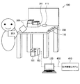
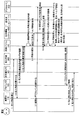
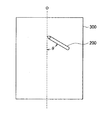
まず、図1を参照して、本発明の第1の実施形態に係る記帳システムの全体概略について説明する。図1に示すように、記帳台装置100は、載置台110、赤外線カメラ101、プロジェクタ103、超音波受信部111、制御パソコン120を有する。制御パソコン120は、通信回路400を介して社内情報システム410と接続されている。なお、図1に示す各構成の配置は一例である。例えば、赤外線カメラ101は、載置台110を撮像できるように配置されていればよい。また、プロジェクタ103は載置台110に情報を投影できるように配置されていればよい。さらに、載置台110には、記入用紙300と、デジタルペン200とが置かれている。以下、図1に示す各構成について説明する。
<1. First Embodiment>
[1-1. Outline of bookkeeping system]
First, an overall outline of a bookkeeping system according to the first embodiment of the present invention will be described with reference to FIG. As shown in FIG. 1, the
載置台110は、プロジェクタ103により情報が投影される、載置台110と一体化された(図示しない)スクリーンを有する。赤外線カメラ101は、載置台110の下方から載置台110を透過して撮像する。プロジェクタ103は、載置台110が有するスクリーンに情報を投影する(図2参照)。デジタルペン200は、筆記可能とする筆記部と、超音波を発振する発振部とを備える。超音波受信部111は、デジタルペン200から発振される超音波を受信する。制御パソコン120は、載置台110に投影する支援情報の表示位置を決定する制御を行なう。制御パソコン120は、顧客が記入用紙300に記入する際の支援情報の表示位置を制御する機器の一例である。社内情報システム410は、載置台110に表示する支援情報や、後述する識別情報などを格納するホストコンピュータを含むシステムである。
The mounting table 110 has a screen (not shown) integrated with the mounting table 110 on which information is projected by the
なお、デジタルペン200の発振部は、超音波に限られず、赤外線を発振してもよい。デジタルペン200の発振部から超音波及び赤外線が発振される場合は、これに応じて、超音波受信部111及び赤外線受光部が必要である。また、デジタルペン200の筆記部は、例えばボールペンであり、インクを吐出して記入用紙300への筆記を可能とする。
Note that the oscillating unit of the
このような記帳システムにおいて、制御パソコン120は、赤外線カメラ101で撮像した載置台110の画像や、超音波受信部111で検出したデジタルペン200の位置に基づき、載置台110上の顧客が見やすい位置に、プロジェクタ103で支援情報を投影させる。これにより、顧客は、記帳台装置100の載置台110上で記帳する際に、載置台110に投影された支援情報を参照することができる。
In such a bookkeeping system, the control
なお、赤外線カメラ101は、載置台110を撮像する撮像部に相当し、載置台上の記入用紙300の位置を算出するための第1のセンサの一例である。また、超音波受信部111は、筆記具から発振される超音波又は赤外線の少なくともいずれかを検知する第2のセンサの一例である。
The
[1−2.記帳台装置の主要部品の配置の一例]
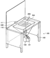
次に、図2を参照して記帳台装置100の主要部品の配置の一例を説明する。図2に示すように、記帳台装置100は箱形状を呈し、上部には超音波受信部111を備えた載置台110が配設されている。載置台110は、光透過性を有する部材から成り、前述したように、情報が投影されるスクリーンを備える。図2では、これらを一体とした光透過体として載置台110を示す。
[1-2. Example of arrangement of main components of bookkeeping device]
Next, an example of the arrangement of main components of the
さらに、記帳台装置100の内部には、載置台110を撮像する赤外線カメラ101と、載置台110に情報を投影するプロジェクタ103が配設されている。また、記帳台装置100の内部の四隅には、赤外線を発光する赤外線発光部102が配設されている。
Furthermore, an
図1に示し、図2に図示していない構成及びその他の構成については、光学系としての赤外線カメラ101及びプロジェクタ103に影響を及ぼさない箇所に配設されることが好ましい。
The configuration shown in FIG. 1 and not shown in FIG. 2 and other configurations are preferably arranged at locations that do not affect the
載置台110の領域500は、プロジェクタ103により支援情報を投影可能な領域であるが、本実施形態はこれに限られない。例えば、プロジェクタ103の配置や性能により、載置台110上の領域であればどこにでも支援情報を投影可能である。
The area 500 of the mounting table 110 is an area where the support information can be projected by the
以上、図2を用いて本実施形態に係る記帳台装置の主要部品の配置について説明したが、図2に示す配置は一例であって、本実施形態はこれに限られない。例えば、超音波受信部111は、デジタルペン200の超音波を受信できる箇所であればどこに配置されてもよい。
As mentioned above, although arrangement | positioning of the main components of the bookkeeping apparatus which concerns on this embodiment was demonstrated using FIG. 2, arrangement | positioning shown in FIG. 2 is an example, Comprising: This embodiment is not restricted to this. For example, the
[1−3.記帳台装置の構成]
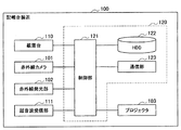
次に、図3を参照して、記帳台装置100の主要な構成について説明する。図3のブロック図に示すように、記帳台装置100は、載置台110、赤外線カメラ101、赤外線発光部102、プロジェクタ103、超音波受信部111、制御部121、HDD(Hard Disk Drive)122、通信部123を有する。なお、制御部121、HDD122及び通信部123は、記帳台装置100が備える制御パソコン120の構成としてもよい。
[1-3. Configuration of bookkeeping device]
Next, the main configuration of the
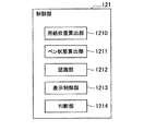
図4に示したように、制御部121は、用紙位置算出部1210、ペン状態算出部1211、認識部1212、表示制御部1213、判断部1214の各ブロックにて示した機能構成を有する。用紙位置算出部1210は、赤外線カメラ101により載置台110を透過して撮像した画像に基づき、載置台110上の記入用紙300の位置を算出する。具体的な算出方法の一例としては、用紙位置算出部1210は、載置台110の左上を(0.0)、右下を(1024.768)とする座標を基準として、赤外線カメラ101により撮像した画像から、載置台110上の記入用紙300の位置座標を算出する。また、記入用紙300の裏のマーカの種別、大きさ、位置、傾きなどから、記入用紙300の位置を算出してもよい。
As shown in FIG. 4, the
ペン状態算出部1211は、デジタルペン200から発振される超音波を受信した超音波受信部111による検出値に基づき、デジタルペン200の位置や傾きやペン先の移動軌跡等の、顧客が把持しているデジタルペン200の状態を算出する。なお、ペン状態算出部1211は、第2のセンサによる検出値に基づき、顧客が把持している筆記具の状態を算出する筆記具状態算出部の一例である。筆記具状態算出部は、ペンのみならず、筆など一般的な筆記具の状態を算出可能である。
The pen state calculation unit 1211 grasps the position and inclination of the
認識部1212は、用紙位置算出部1210で算出された記入用紙の位置に対する、ペン状態算出部1211で算出されたデジタルペン200の状態に基づき、載置台110上の顧客の利き手を認識する。認識部1212による顧客の利き手の認識についての詳細は、[1−4.記帳台装置の動作]で述べる。
The
表示制御部1213は、認識部1212により認識された利き手に基づき、支援情報の表示位置を決定する。表示制御部1213は、決定した表示位置に所定の支援情報を表示させるよう、プロジェクタ103を制御する。ここで、支援情報とは、ヘルプ情報や見本など、顧客が記入用紙に所定事項を記入する際に記入を支援するための情報である。所定の支援情報とは、例えば、後述する判断部1214で判断された記入用紙の種別が複数ある場合には、種別に対応した支援情報である。
The
表示制御部1213は、ヘルプ情報として、ヘルプボタンのみを表示させ、ヘルプ情報表示の指示を検知した場合にヘルプ内容を表示させてもよい。ヘルプ情報表示の指示の検知とは、例えば、超音波受信部111による検出値や赤外線カメラ101で撮像した画像に基づいたデジタルペン200の位置が、ヘルプボタンの表示位置と重複した場合に、ヘルプ情報表示の指示を検知してもよい。
The
また、表示制御部1213は、ヘルプ情報として、記入用紙内の記入を禁止する欄に、記入を禁止することを示す情報を表示してよい。例えば、記入禁止の文字を所定の禁止欄に投影させたり、禁止欄のみ赤く照射(赤い画像を投影)させたりしてもよい。記入用紙内の記入を禁止する欄の判断は、記入用紙の種別に応じた記入禁止欄の情報を社内情報システム410から取得し、撮像した記入用紙の撮像データから該当する欄の位置を判断してもよい。なお、表示制御部1213による表示制御の詳細は、[1−4.記帳台装置の動作]で述べる。
In addition, the
判断部1214は、記入用紙のサイズ又は記入用紙の識別情報に対応付けられた記入用紙の種別を示す種別情報と、赤外線カメラ101により撮像された記入用紙の画像と、に基づき、記入用紙の種別を判断する。判断部1214による種別判断の詳細は、[1−4.記帳台装置の動作]で述べる。
The
[1−4.記帳台装置の動作]
次に、図5を参照して、本実施形態に係る記帳台装置100の動作処理について説明する。図5は、本実施形態に係る記帳台装置100の動作処理を示すタイムチャートである。
[1-4. Operation of bookkeeping device]
Next, with reference to FIG. 5, the operation process of the
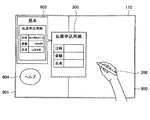
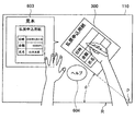
図5において、まず、顧客が特定の記入用紙300を選び、載置台110に記入用紙300を置く(ステップ1.1)。この際、プロジェクタ103は、載置台110上に予めスタート画像を表示していてもよい。スタート画像の一例を、図6に示す。図6に示すスタート画像は載置台上に表示され、記入用紙300の一例である帳票の配置場所を示す矢印及び「帳票」の文字を含んだ表示部分600と、デジタルペン200の配置場所を示す矢印及び「ペン」の文字を含んだ表示部分601と、顧客に動作を促すための文字を含んだ表示部分602を含む。これにより、顧客は、表示部分602の指示(「ペンを取り、記入する帳票を置いてください」)に従い、記入用紙300を載置台110に置き、デジタルペンを把持する(ステップ1.2)。
In FIG. 5, the customer first selects a
次いで、赤外線カメラ101が記入用紙300の裏面を撮像する(ステップ2.1)。図2に示したように、赤外線カメラ101は載置台110の下方に配置され、載置台110に載置された記入用紙300の裏面を撮像することができる。赤外線カメラ101で撮像された画像は、制御パソコン120に送られる(ステップ2.2)。
Next, the
次いで、制御パソコン120の判断部1214では、送られた画像に基づき記入用紙の種別を判断する(ステップ2.3)。具体的には、判断部1214は、記入用紙のサイズ又は記入用紙の識別情報に対応付けられた記入用紙の種別を示す種別情報と、赤外線カメラ101により撮像された記入用紙の画像とに基づき、記入用紙の種別を判断する。
Next, the
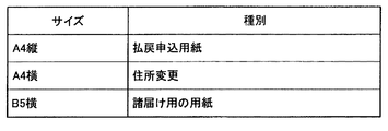
種別情報が記入用紙のサイズに対応付けられて記憶領域に記憶されている場合には、撮像した画像から記入用紙の大きさを判定し、種別情報から、判定された記入用紙の大きさに対応する記入用紙の種別を判断する。図7Aに示した記入用紙300の大きさ(サイズ)がA4縦の場合、図8から、図7Aに示す記入用紙の種別は「払戻申込用紙」と判断される。
If the type information is stored in the storage area in association with the size of the entry form, the size of the entry form is determined from the captured image, and the type information is determined from the type information. Determine the type of entry form to be used. When the size (size) of the
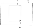
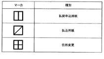
種別情報が記入用紙の識別情報に対応付けて記憶領域に記憶されている場合の記入用紙300の種別判断について図7A、図7B及び図8を参照して説明する。なお、記入用紙の識別情報は、マーカ、バーコードなどの図形や、文字であってもよい。図7Aは、赤外線カメラ101で記入用紙の裏面を撮像した画像の一例である。本実施形態に係る赤外線カメラ101は、上述したように、載置台110を透過して記入用紙300の裏面を撮像する。判断部1214は、記入用紙300の裏面のマーカ710と、図7Bに示す種別情報に基づき、用紙の種別を判断する。図7Aに示した記入用紙の識別情報(マーカ710)の場合、図7Bから図7Aに示す記入用紙の種別は、「払戻申込用紙」と判断される。
The determination of the type of the
種別情報は、HDD122に格納されていてもよいし、社内システム400に含まれるホストコンピュータに格納されていてもよい。種別情報がホストコンピュータに格納されている場合は、判断部1214は、送られた画像から記入用紙のサイズ情報又は識別情報を取得し、取得した情報を通信部123を介してホストコンピュータに送信し、該送信した情報に対応する種別情報をホストコンピュータから受信してもよい。
The type information may be stored in the
以上に説明したように、記入用紙の裏面情報から記入用紙の種別を判断した後(図5のステップ2.3)、制御パソコン120は、記入用紙の種別に対応する支援情報を社内情報システム400から取得する(ステップ2.4)。ここで、社内情報システム400では、支援情報が最新の状態に管理されているため(更新管理)、制御パソコン120は、更新された支援情報を社内情報システム400から取得できる。これにより、記帳台装置100は、記入用紙への支援情報を最新の状態で表示することができる。
As described above, after determining the type of entry form from the back side information of the entry form (step 2.3 in FIG. 5), the control
一方、顧客はデジタルペン200を把持して操作する(ステップ3.1)。顧客が把持するデジタルペン200からは、超音波が発振される。超音波センサ111は、デジタルペン200から発振される超音波を検出する(ステップ3.2)。
On the other hand, the customer grasps and operates the digital pen 200 (step 3.1). Ultrasonic waves are oscillated from the
次いで、超音波センサ110は、超音波の検出値を制御パソコン120に送る(ステップ3.3)。制御パソコン120のペン状態算出部1211は、超音波センサ110から受け取った検出値に基づき、載置台110上のデジタルペン200の位置を算出する。
Next, the
なお、本実施形態では、デジタルペン200から発振される超音波の検出値に基づいてデジタルペン200の位置を算出するが、本実施形態はこれに限られない。例えば、デジタルペン200から赤外線(光)と超音波(音)が同時に発振され、記帳台装置が備える距離センサ及び2つの超音波センサを用い、デジタルペン200からの赤外線を距離センサが受取ってから、2つの超音波センサがそれぞれ超音波を受取るまでの時間から、デジタルペン200の位置を算出してもよい。
In the present embodiment, the position of the
次いで、制御パソコン120の認識部1212は、記入用紙300の位置に対するデジタルペン200の位置に基づき、顧客の利き手を認識する(ステップ3.4)。デジタルペン200の位置は、上述したようにペン状態算出部1211により算出される。また、記入用紙300の位置は、用紙位置算出部1210により算出される。
Next, the
ここで、認識部1212による利き手認識について説明する。例えば、認識部1212は、顧客が把持するデジタルペン200の位置が、記入用紙の位置よりも右側にあれば右利き、左側にあれば左利きと認識する。具体的には、載置台110の左上を(0.0)、右下を(1024.768)とする座標を基準として、載置台110上の記入用紙300のx座標と、デジタルペン200のx座標とを比較し、顧客の利き手を認識する。ここでx軸は、載置台110の横方向の軸をいう。
Here, dominant hand recognition by the
例えば、記入用紙300の左上を起点とし、かかる起点のx座標に記入用紙の横幅を足した数値よりも、デジタルペン200のx座標が大きい場合は、右利きと認識する。また、記入用紙300の左上を起点とし、かかる起点のx座標よりもデジタルペン200のx座標が小さい場合は、左利きと認識する。なお、記入用紙300の起点は任意に設定できる。起点のx座標に足す記入用紙の横幅の数値は、判断部1214で判断された記入用紙の種別に基づいてもよく、用紙位置算出部1210により、記入用紙300の左上の座標と右上の座標とから算出してもよい。
For example, if the x coordinate of the
次いで、表示制御部1213は、認識部1212により認識された利き手に基づき、支援情報の表示位置を、顧客が見えやすい位置に決定する(ステップ3.5)。例えば、表示制御部1213は、記入用紙300の位置に対して、認識部1212により認識された利き手の位置とは反対側の載置台110の領域に、支援情報を表示する。
Next, based on the dominant hand recognized by the
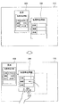
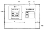
具体的には、図9に示すように、顧客の利き手が右利きと認識された場合は、記入用紙300の左側の領域801(少なくとも領域800と記入用紙300が載置された領域以外の領域)の内部に、支援情報(見本情報603、ヘルプ情報604)を表示する。また、図10に示すように、顧客の利き手が左利きと認識された場合は、記入用紙300の右側の領域811(少なくとも領域810と記入用紙300が載置された領域以外の領域)の内部に支援情報を表示する。
Specifically, as shown in FIG. 9, when the customer's dominant hand is recognized as right-handed, an
次いで、表示制御部1213で決定された表示位置に支援情報を表示するよう、プロジェクタ103に照射指示が送られる(ステップ4.1)。表示制御部1213が命令を受けたプロジェクタ103は、載置台110が有するスクリーンに、支援情報を投影する(ステップ4.2)。
Next, an irradiation instruction is sent to the
次いで、顧客は載置台110上で支援情報を参照しながら記入用紙300へ所定事項を記入する(ステップ5)。
Next, the customer enters predetermined items on the
以上説明したように、本実施形態によれば、顧客の利き手を考慮して利き手が位置しないと予測される側に、記入用紙の見本等の支援情報を表示する。この結果、支援情報の表示がペンを持つ利き手により遮られない。このため、顧客は支援情報を見ながら記入例に従い、ミスなく迅速に記入用紙に所定事項を記入することができる。また、表示される支援情報は更新されたものであるため、顧客は最新の支援情報を見ながら記入用紙に所定事項を記入することができる。 As described above, according to the present embodiment, support information such as a sample form is displayed on the side where the dominant hand is predicted not to be positioned in consideration of the dominant hand of the customer. As a result, the support information display is not blocked by the dominant hand holding the pen. For this reason, the customer can fill in the predetermined items on the entry form promptly without making a mistake according to the entry example while viewing the support information. Further, since the displayed support information is updated, the customer can enter predetermined items on the entry form while viewing the latest support information.
<2.第2の実施形態>
次に、本発明の第2の実施形態に係る記帳台装置の表示制御について図11を参照して説明する。本実施形態では、記帳台装置の用紙位置算出部1210は、記入用紙300の位置を繰り返し算出する。用紙位置算出部1210が繰り返し算出するタイミングは任意の所定の間隔でもよい。
<2. Second Embodiment>
Next, display control of the bookkeeping apparatus according to the second embodiment of the present invention will be described with reference to FIG. In the present embodiment, the paper position calculation unit 1210 of the bookkeeping apparatus repeatedly calculates the position of the
用紙位置算出部1210が記入用紙300の位置を繰り返し算出することにより、表示制御部1213は、記入用紙300の位置の経時的変化を把握する。表示制御部1213は、記入用紙300の位置の変化に応じて支援情報の表示位置を変更する。
When the paper position calculation unit 1210 repeatedly calculates the position of the
例えば図11の上側に示した記入用紙300が、下側に示したように右から左へ移動すると、表示制御部1213は、その位置の経時的変化に基づき、見本情報603の表示位置を右から左に変更する。これによって、記入用紙300が移動しても、支援情報を見やすい位置に表示することにより、顧客はミスなく記入用紙300に必要な事項を記入する環境を維持することができる。
For example, when the
<3.第3の実施形態>
次に、本発明の第3の実施形態に係る記帳台装置の表示制御について図12及び図13を参照して説明する。
<3. Third Embodiment>
Next, display control of the bookkeeping apparatus according to the third embodiment of the present invention will be described with reference to FIGS.
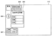
本実施形態に係る表示制御部1213は、縮小、分割又はスクロールの少なくともいずれかの表示方法を用いて、支援情報を表示させる。例えば、図12に示すように、見本を画像606と画像607に分割して表示することができる。
The
このような表示制御部1213による縮小、分割、スクロール表示制御は、利き手と反対側の領域の広さと、表示すべき支援情報の量とに応じて制御される。
Such reduction, division, and scroll display control by the
また、本実施形態に係る表示制御部1213は、利き手と反対側の領域に、表示すべき支援情報が表示しきれない場合は、その支援情報の一部又は全部を、載置台110上の他の領域に表示させることができる。例えば、図13に示すように、顧客の利き手が右利きと判断された場合は、表示制御部1213は、記入用紙300の左側の領域に支援情報を表示させるよう制御するが、ヘルプ情報604しか表示出来ない場合は、見本情報603のみ、又は、ヘルプ情報604と見本情報603の両方を記入用紙300の右側の領域に表示させることができる。このとき、表示制御部1213は、赤外線カメラ110で撮像した画像に基づき、載置台110を透過して撮像された顧客の利き手を判断し、支援情報を、利き手を避けて利き手側の領域に表示させることもできる。
In addition, when the support information to be displayed cannot be displayed in the area opposite to the dominant hand, the
<4.第4の実施形態>
次に、本発明の第4の実施形態について図14及び図15を参照して説明する。上述した第1の実施形態では、認識部1212による顧客の利き手の認識を、記入用紙300の位置に対するデジタルペン200の位置で判断しているが、本実施形態では、デジタルペン200の位置以外の同ペン200の状態に基づき、顧客の利き手を認識する。
<4. Fourth Embodiment>
Next, a fourth embodiment of the present invention will be described with reference to FIGS. In the first embodiment described above, the recognition of the dominant hand of the customer by the
例えば、認識部1212は、図14に示すように、デジタルペン200の移動軌跡212に基づいて顧客の利き手を認識する。つまり、ペン状態算出部1211により、デジタルペン200の移動軌跡212を算出し、用紙位置算出部1210により算出された記入用紙300の位置に対するデジタルペン200の移動軌跡212に基づき、顧客の利き手が判断される。具体的には、例えば、図14のようにx軸に対して右側方向から左側方向にデジタルペン200が移動した場合は、右利きと認識し、x軸に対して左側方向から右側方向にデジタルペン200が移動した場合は、左利きと認識する。
For example, the
また、認識部1212は、図15に示すように、記入用紙300に対するデジタルペン200の傾きに基づいて顧客の利き手を認識することができる。かかるデジタルペン200の傾きは、記入用紙300の任意の所定の軸に対する傾きθである。図15では、記入用紙300の長手方向(縦方向)を軸Oとしたときのその軸Oとペン200とのなす角を傾きθとしている。
Further, as shown in FIG. 15, the
上記デジタルペン200の傾きは、ペン状態算出部1211により算出される。ペン状態算出部1211は、顧客が把持するデジタルペン200から発振される超音波を受信する超音波受信部111による検出値に基づき、顧客が把持しているデジタルペン200の状態を算出してもよい。
The tilt of the
また、ペン状態算出部1211は、赤外線カメラ101が載置台110を透過して撮像したデジタルペン200のペン先側の画像に基づいて、デジタルペン200の傾きを算出してもよい。この場合、ペン状態算出部1211は、赤外線線カメラ101が撮像した画像と、予めシステム400やHDD122に登録されているデジタルペン200のペン先側の画像とを比較して、撮像した画像からペン先側の画像の傾きを算出してもよい。
Further, the pen state calculation unit 1211 may calculate the tilt of the
認識部1212は、このように算出した記入用紙300の任意の所定の軸に対するデジタルペン200の傾きθに基づき、顧客の利き手を認識する。例えば、認識部1212は、軸Oとデジタルペン200とのなす角(傾きθ)の符号の正負により、右利き又は左利きを判断してもよい。傾きθと対応する利き手についての情報は、HDDやホストコンピュータから取得してもよいし、算出した傾きθをホストコンピュータに送信し、対応する利き手の情報をホストコンピュータから受信してもよい。
The
<5.第5の実施形態>
次に、本発明の第5の実施形態について図16を参照して説明する。上述した第1の実施形態では、認識部1212による顧客の利き手の認識を、記入用紙300の位置に対するデジタルペン200の位置で判断しているが、本実施形態では、記入用紙300の傾きθに基づいて、顧客の利き手を認識する。具体的には、認識部1212は、図16に示すように、載置台110の顧客に対向する載置台110の縁部Rに対する、記入用紙300の傾きθ’に基づいて、顧客の利き手を認識する。図16に示すように記入用紙300が左に傾いていれば右利きと判断し、右に傾いていれば左利きと判断する。記入用紙300が左右いずれの方向に傾いているかについては、まず、用紙位置算出部1210が、赤外線カメラ101で撮像した画像に基づき、記入用紙の位置を算出し、次いで認識部1212が、用紙位置算出部1210で算出された記入用紙300の位置と、載置台110の縁部のうち顧客に対向する縁部Rとから、傾きθ’の符号の正負により、顧客の利き手を認識する。
<5. Fifth Embodiment>
Next, a fifth embodiment of the present invention will be described with reference to FIG. In the first embodiment described above, the recognition of the dominant hand of the customer by the
記入用紙の傾きθ’は、図16に示すように、記入用紙の長手方向の軸Pと、載置台110の顧客に対向する縁部Rとの角度から求められる。記入用紙のいずれの辺を記入用紙の軸Pとするかについては、撮像された記入用紙に印字されている文字の縦・横や、判断部1214により判断された記入用紙の種別に基づく記入用紙の各辺の長さと縦・横の関係から判断してもよい。
As shown in FIG. 16, the inclination θ ′ of the entry sheet is obtained from the angle between the longitudinal axis P of the entry sheet and the edge R of the mounting table 110 facing the customer. Which side of the entry form is used as the axis P of the entry form is determined based on the length and width of the characters printed on the imaged entry form and the type of entry form determined by the
<6.第6の実施形態>
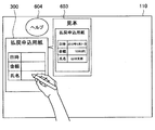
次に、本発明の第6の実施形態について図17を参照して説明する。上述した第1の実施形態では、認識部1212による顧客の利き手の認識を行い、表示制御部1213が、認識された顧客の利き手に基づき、支援情報の表示位置を決定した。一方、本実施形態では、表示制御部1213が、図17に示すように、載置台110上の記入用紙300の位置に基づき、記入用紙300以外の載置台110上の領域のうち、記入用紙の右側の領域及び左側の領域いずれか広い領域に、支援情報の表示位置を決定する。
<6. Sixth Embodiment>
Next, a sixth embodiment of the present invention will be described with reference to FIG. In the first embodiment described above, the
記入用紙の右側の領域及び左側の領域のうちいずれが広い領域であるかの判断は、例えば、記入用紙300の両端からそれぞれ載置台110上の端までの各距離を比較し、いずれが広い領域であるかを判断してもよい。ここで、図17では、載置台110上の端までの距離a、bを比較している。
The determination of which of the right area and the left area of the entry form is a wider area is made by comparing the distances from both ends of the
比較の結果、図17では距離bが距離aより長いため、記入用紙300の左側の領域820が右側の領域822より広いと判断され、左側の領域820に見本情報603が表示される。
As a result of comparison, since the distance b is longer than the distance a in FIG. 17, it is determined that the
なお、上記第1の実施形態から第6の実施形態までの各実施形態の組み合わせにより、支援情報の表示位置を決定することが可能である。 Note that the display position of the support information can be determined by a combination of the embodiments from the first embodiment to the sixth embodiment.
例えば、利き手認識が出来ない場合や、記入用紙の位置に対して利き手の位置とは反対側の領域に表示出来ない場合に、第6の実施形態に係る表示制御を実施してもよい。 For example, the display control according to the sixth embodiment may be performed when the dominant hand cannot be recognized or when it cannot be displayed in the area opposite to the dominant hand position with respect to the position of the entry sheet.
<7.まとめ>
以上説明したように、本発明の各実施形態に係る記帳台装置は、見本やヘルプ情報などの支援情報を顧客の見やすい位置に表示させるため、顧客は見本やヘルプ情報などを見ながら簡単に記入用紙への記入ができる。これにより、顧客の記入用紙の選択や記入事項の誤りを未然に防ぎ、記帳台の利便性を向上させることができる。
<7. Summary>
As described above, since the bookkeeping apparatus according to each embodiment of the present invention displays support information such as samples and help information in a position that is easy for the customer to see, the customer can easily enter while viewing the samples and help information. You can fill in the form. As a result, it is possible to prevent the customer from selecting an entry form and making an entry error, and improve the convenience of the bookkeeping table.
また、支援情報を顧客の見やすい位置に表示させるため、記帳台のスペースが狭くても、顧客は支援情報を十分に参照できる。 Further, since the support information is displayed at a position that is easy to see for the customer, the customer can sufficiently refer to the support information even if the space for the bookkeeping is small.
また、本発明の実施形態によれば、記入用紙300の位置の変化に応じて支援情報の表示位置を変更することができる。
Further, according to the embodiment of the present invention, the display position of the support information can be changed according to the change of the position of the
また、本発明の実施形態によれば、縮小、分割又はスクロールの少なくともいずれかの表示方法を用いて、支援情報を表示させることができる。 In addition, according to the embodiment of the present invention, the support information can be displayed using at least one of the display methods of reduction, division, and scroll.
また、本発明の実施形態によれば、利き手の位置と反対側の領域に表示しきれない支援情報の一部又は全部を、載置台110上の他の領域に表示させることができる。 Further, according to the embodiment of the present invention, part or all of the support information that cannot be displayed in the area opposite to the position of the dominant hand can be displayed in another area on the mounting table 110.
また、本発明の実施形態によれば、デジタルペン200の移動軌跡や、傾きに基づいて顧客の利き手を認識することができる。
Further, according to the embodiment of the present invention, the dominant hand of the customer can be recognized based on the movement trajectory and inclination of the
また、本発明の実施形態によれば、記入用紙300の傾きに基づいて顧客の利き手を認識することができる。
Further, according to the embodiment of the present invention, the dominant hand of the customer can be recognized based on the inclination of the
また、本発明の実施形態によれば、記入用紙300の位置に基づき、記入用紙300以外の載置台110上の領域のうち、記入用紙の右側の領域及び左側の領域いずれか広い領域に、支援情報の表示位置を決定することができる。
In addition, according to the embodiment of the present invention, based on the position of the
なお上記各実施形態では、本発明の第1のセンサとして有する撮像部の一例として、赤外線カメラ101を用いている。これにより以下のような効果がある。
In each of the above embodiments, the
(1)プロジェクタ103との併用
本発明の実施形態に係る記帳台装置では、載置台110が備えるスクリーンにプロジェクタ103から支援情報の投影を行なっている。したがって、プロジェクタ103の照射により、記入用紙300が載置される載置台110の輝度は高い。このように輝度が高い環境でも、可視光線より波長が長く、一般光源やプロジェクタ照射の影響を受け難い赤外線を用いる赤外線カメラによれば、撮像した画像から記入用紙の位置や記入用紙裏のマーカなどを確実に読み取ることが出来る。
(1) Combined use with
(2)載置台110を透過して撮像
赤外線は可視光に比べて波長が長く、散乱し難い性質がある。例えば、煙や薄い布などを透過して向こう側の物体を撮影するために最適である。本発明の実施形態に係る記帳台装置では、スクリーンの向こう側にある記入用紙(特に記入用紙裏のマーカ)などを確実に撮像するため、赤外線カメラが用いられる。
(2) Imaging through the mounting table 110 Infrared rays have a longer wavelength than visible light and are difficult to scatter. For example, it is optimal for photographing an object on the other side through smoke or a thin cloth. In the bookkeeping apparatus according to the embodiment of the present invention, an infrared camera is used to reliably image an entry sheet (in particular, a marker on the back of the entry sheet) on the other side of the screen.
(3)眩しさの防止
撮像のための載置台110への照射が、顧客に眩しくないようにするため、赤外線カメラを用いる。赤外線は目に見えないため、記帳台装置に近赤外線光源を備え、載置台110を照射しても顧客は眩しく感じない。
(3) Prevention of glare The infrared camera is used so that irradiation to the mounting table 110 for imaging is not dazzled by the customer. Since infrared rays are not visible, the customer does not feel dazzling even if the table device is provided with a near infrared light source and the mounting table 110 is irradiated.
以上、添付図面を参照しながら本発明の好適な実施形態について詳細に説明したが、本発明はかかる例に限定されない。本発明の属する技術の分野における通常の知識を有する者であれば、特許請求の範囲に記載された技術的思想の範疇内において、各種の変更例または修正例に想到し得ることは明らかであり、これらについても、当然に本発明の技術的範囲に属するものと了解される。 The preferred embodiments of the present invention have been described in detail above with reference to the accompanying drawings, but the present invention is not limited to such examples. It is obvious that a person having ordinary knowledge in the technical field to which the present invention pertains can come up with various changes or modifications within the scope of the technical idea described in the claims. Of course, it is understood that these also belong to the technical scope of the present invention.
例えば、上記各実施形態では、金融機関に設置される記帳台装置での帳票記入場面を想定して説明したが、本発明は、病院などの受付場面や、電話会社の契約場面、保険会社の契約場面、交通機関の定期券購入場面にも応用できる。 For example, in each of the above-described embodiments, the description has been made on the assumption that a form entry scene in a bookkeeping apparatus installed in a financial institution has been described, but the present invention can be applied to a reception scene such as a hospital, a telephone company contract scene, an insurance company It can also be applied to contracts and transportation commuter pass purchases.
100 記帳台装置
101 赤外線カメラ
103 プロジェクタ
110 載置台
111 超音波受信部
120 制御パソコン
121 制御部
122 HDD
123 通信部
1210 用紙位置算出部
1211 ペン状態算出部
1212 認識部
1213 表示制御部
1214 判断部
200 デジタルペン
300 記入用紙
301 記入用紙入れ
400 通信回路
410 社内情報システム
DESCRIPTION OF
123 communication unit 1210 paper position calculation unit 1211 pen
Claims (17)
第1のセンサによる検出値に基づき、前記載置台上の前記記入用紙の位置を出力する用紙位置出力部と、
第2のセンサによる検出値に基づき、顧客が把持している筆記具の状態を出力する筆記具状態出力部と、
前記記入用紙の位置に対する前記筆記具の状態に基づき、前記記入用紙の位置に対して前記筆記具の位置とは反対側の載置台の領域に、前記顧客が前記記入用紙に記入する際の支援情報の表示位置を決定する表示制御部と、
を備える、表示制御装置。 A mounting table on which an entry form is placed;
A sheet position output unit that outputs a position of the entry sheet on the mounting table based on a detection value by the first sensor;
A writing instrument state output unit for outputting the state of the writing instrument held by the customer based on the detection value by the second sensor;
Based on the state of the writing instrument with respect to the position of the entry sheet, support information for the customer to fill in the entry sheet in the area of the mounting table opposite to the position of the writing instrument with respect to the position of the entry sheet A display control unit for determining a display position;
A display control device.
前記筆記具状態出力部は、前記撮像部により撮像された画像のうち筆記具のペン先側の画像から、前記筆記具の傾きを出力する、請求項3に記載の表示制御装置。 An imaging unit that images the mounting table as the first sensor;
The display control apparatus according to claim 3 , wherein the writing instrument state output unit outputs an inclination of the writing instrument from an image on a pen tip side of the writing instrument among images captured by the imaging unit.
前記表示制御部は、前記算出された筆記具の移動軌跡に基づき、支援情報の表示位置を決定する、請求項1〜4のいずれか1項に記載の表示制御装置。 The writing instrument state output unit calculates a movement locus of the writing instrument as the state of the writing instrument,
Wherein the display control unit, based on the movement locus of the calculated writing instruments, to determine the display position of the support information, the display control device according to any one of claims 1-4.
前記用紙位置出力部は、前記撮像部により撮像された画像に基づき、前記載置台上の前記記入用紙の位置を算出する、請求項1〜6のいずれか1項に記載の表示制御装置。 An imaging unit that images the mounting table as the first sensor;
The sheet position output unit, based on the image captured by the imaging unit calculates the position of the input form on the mounting table, the display control device according to any one of claims 1-6.
前記表示制御部は、前記判断された記入用紙の種別に対応する支援情報を表示させる、請求項7記載の表示制御装置。 The type of the entry sheet is determined based on the type information indicating the size of the entry sheet or the type of the entry sheet associated with the identification information of the entry sheet and the image of the entry sheet imaged by the imaging unit. And a determination unit that
The display control apparatus according to claim 7 , wherein the display control unit displays support information corresponding to the determined type of entry form.
前記表示制御部は、前記算出された記入用紙の位置の変化に応じて前記支援情報の表示位置を変更する、請求項1〜8のいずれか1項に記載の表示制御装置。 The sheet position output unit repeatedly calculates the position of the entry sheet,
Wherein the display control unit changes the display position of the support information in response to a change in position of input form the calculated display control apparatus according to any one of claims 1-8.
前記表示制御部は、前記プロジェクタを用いて前記スクリーンに前記支援情報を表示させる、請求項1〜14のいずれか1項に記載の表示制御装置。 A projector for projecting information on a screen provided in the mounting table;
Wherein the display control unit displays the support information to the screen using the projector, the display control device according to any one of claims 1-14.
第2のセンサによる検出値に基づき、顧客が把持している筆記具の状態を出力するステップと、
前記記入用紙の位置に対する前記筆記具の状態に基づき、前記記入用紙の位置に対して前記筆記具の位置とは反対側の載置台の領域に、前記顧客が前記記入用紙に記入する際の支援情報の表示位置を決定するステップと、
を含む、表示制御方法。 Outputting a position of the entry sheet on a mounting table on which the entry sheet is placed based on a detection value by the first sensor;
Outputting a state of the writing instrument held by the customer based on the detection value by the second sensor;
Based on the state of the writing instrument with respect to the position of the entry sheet, support information for the customer to fill in the entry sheet in the area of the mounting table opposite to the position of the writing instrument with respect to the position of the entry sheet Determining a display position;
Including a display control method.
第2のセンサによる検出値に基づき、顧客が把持している筆記具の状態を出力する処理と、
前記出力された記入用紙の位置に対する前記出力された筆記具の状態に基づき、前記記入用紙の位置に対して前記筆記具の位置とは反対側の載置台の領域に、前記顧客が前記記入用紙に記入する際の支援情報の表示位置を決定する処理と、
をコンピュータに実行させる、プログラム。 A process of outputting the position of the entry sheet on the mounting table on which the entry sheet is placed based on a detection value by the first sensor;
A process of outputting the state of the writing instrument held by the customer based on the detection value by the second sensor;
Based on the state of the output writing instrument with respect to the position of the output entry form, the customer fills in the entry form in the area of the mounting table opposite to the position of the writing instrument with respect to the position of the entry form. Processing for determining the display position of the support information when
A program that causes a computer to execute.
Priority Applications (1)
| Application Number | Priority Date | Filing Date | Title |
|---|---|---|---|
| JP2014028534A JP5773003B2 (en) | 2014-02-18 | 2014-02-18 | Display control apparatus, display control method, and program |
Applications Claiming Priority (1)
| Application Number | Priority Date | Filing Date | Title |
|---|---|---|---|
| JP2014028534A JP5773003B2 (en) | 2014-02-18 | 2014-02-18 | Display control apparatus, display control method, and program |
Related Parent Applications (1)
| Application Number | Title | Priority Date | Filing Date |
|---|---|---|---|
| JP2010157735A Division JP5482522B2 (en) | 2010-07-12 | 2010-07-12 | Display control apparatus, display control method, and program |
Publications (2)
| Publication Number | Publication Date |
|---|---|
| JP2014132478A JP2014132478A (en) | 2014-07-17 |
| JP5773003B2 true JP5773003B2 (en) | 2015-09-02 |
Family
ID=51411493
Family Applications (1)
| Application Number | Title | Priority Date | Filing Date |
|---|---|---|---|
| JP2014028534A Expired - Fee Related JP5773003B2 (en) | 2014-02-18 | 2014-02-18 | Display control apparatus, display control method, and program |
Country Status (1)
| Country | Link |
|---|---|
| JP (1) | JP5773003B2 (en) |
Families Citing this family (5)
| Publication number | Priority date | Publication date | Assignee | Title |
|---|---|---|---|---|
| JP5969551B2 (en) * | 2014-07-22 | 2016-08-17 | 日本電信電話株式会社 | Mobile terminal with multi-touch screen and operation method thereof |
| JP6421528B2 (en) * | 2014-10-03 | 2018-11-14 | 富士通株式会社 | Display control program, display control method, and information processing apparatus |
| US12230029B2 (en) * | 2017-05-10 | 2025-02-18 | Humane, Inc. | Wearable multimedia device and cloud computing platform with laser projection system |
| US10924651B2 (en) | 2017-05-10 | 2021-02-16 | Humane, Inc. | Wearable multimedia device and cloud computing platform with application ecosystem |
| JP7334097B2 (en) * | 2019-09-09 | 2023-08-28 | Toppanエッジ株式会社 | Form data creation device, form data creation method |
Family Cites Families (7)
| Publication number | Priority date | Publication date | Assignee | Title |
|---|---|---|---|---|
| JP4661387B2 (en) * | 2005-06-20 | 2011-03-30 | 富士ゼロックス株式会社 | Information processing apparatus, information processing method, and computer program |
| JP2007226577A (en) * | 2006-02-23 | 2007-09-06 | Dainippon Printing Co Ltd | Data input processing system, terminal device and computer program using digital pen |
| JP4773261B2 (en) * | 2006-04-26 | 2011-09-14 | 日立オムロンターミナルソリューションズ株式会社 | Form processing device |
| JP2008033049A (en) * | 2006-07-28 | 2008-02-14 | Ricoh Co Ltd | Object indication device |
| JP2009169735A (en) * | 2008-01-17 | 2009-07-30 | Sharp Corp | Information processing display device |
| JP2010009542A (en) * | 2008-06-30 | 2010-01-14 | Pentel Corp | Electronic pen |
| JP5482522B2 (en) * | 2010-07-12 | 2014-05-07 | 沖電気工業株式会社 | Display control apparatus, display control method, and program |
-
2014
- 2014-02-18 JP JP2014028534A patent/JP5773003B2/en not_active Expired - Fee Related
Also Published As
| Publication number | Publication date |
|---|---|
| JP2014132478A (en) | 2014-07-17 |
Similar Documents
| Publication | Publication Date | Title |
|---|---|---|
| JP5482522B2 (en) | Display control apparatus, display control method, and program | |
| US8970886B2 (en) | Method and apparatus for supporting user's operation of image reading apparatus | |
| US7176881B2 (en) | Presentation system, material presenting device, and photographing device for presentation | |
| CN105308549B (en) | Information processing unit, control method, program and storage medium | |
| US9324134B2 (en) | Display apparatus and control method thereof | |
| JP5773003B2 (en) | Display control apparatus, display control method, and program | |
| CN101262586A (en) | Information sharing support system, information processing device and computer control method | |
| JP2000105671A (en) | Coordinate input / detection device and electronic blackboard system | |
| JP2008176802A (en) | Coordinate input / detection device and electronic blackboard system | |
| US20140285524A1 (en) | Image processing device, projector, and image processing method | |
| US9485372B2 (en) | Image forming apparatus | |
| JP2016114963A (en) | Input operation detection device, projector device, electronic blackboard device, digital signage device, and projector system | |
| JPWO2017130504A1 (en) | Image projection device | |
| CN107407994A (en) | Interactive projector and interactive projection system | |
| JP5657471B2 (en) | Digital platform device | |
| JP6528964B2 (en) | INPUT OPERATION DETECTING DEVICE, IMAGE DISPLAY DEVICE, PROJECTOR DEVICE, PROJECTOR SYSTEM, AND INPUT OPERATION DETECTING METHOD | |
| JP2000259338A (en) | Input system, display system, presentation system, and information storage medium | |
| JP4589619B2 (en) | Paper document information operation system and information operation method | |
| WO2023228730A1 (en) | Information processing device, information processing system, information processing method, and non-transitory computer-readable medium with program stored therein | |
| US20160334892A1 (en) | Display unit manager | |
| JP6187547B2 (en) | Information processing apparatus, control method and program thereof, and information processing system, control method and program thereof | |
| JP4951266B2 (en) | Display device, related information display method and program | |
| JP2013070218A (en) | Projection apparatus | |
| JP4979895B2 (en) | Display control apparatus, display control method, display control program, and display | |
| KR20190027081A (en) | Electronic apparatus, method for controlling thereof and the computer readable recording medium |
Legal Events
| Date | Code | Title | Description |
|---|---|---|---|
| A131 | Notification of reasons for refusal |
Free format text: JAPANESE INTERMEDIATE CODE: A131 Effective date: 20150317 |
|
| A521 | Request for written amendment filed |
Free format text: JAPANESE INTERMEDIATE CODE: A523 Effective date: 20150514 |
|
| TRDD | Decision of grant or rejection written | ||
| A01 | Written decision to grant a patent or to grant a registration (utility model) |
Free format text: JAPANESE INTERMEDIATE CODE: A01 Effective date: 20150602 |
|
| A61 | First payment of annual fees (during grant procedure) |
Free format text: JAPANESE INTERMEDIATE CODE: A61 Effective date: 20150615 |
|
| R150 | Certificate of patent or registration of utility model |
Ref document number: 5773003 Country of ref document: JP Free format text: JAPANESE INTERMEDIATE CODE: R150 |
|
| LAPS | Cancellation because of no payment of annual fees |