JP5772321B2 - Vehicle detection device, vehicle detection method, and program - Google Patents
Vehicle detection device, vehicle detection method, and program Download PDFInfo
- Publication number
- JP5772321B2 JP5772321B2 JP2011154318A JP2011154318A JP5772321B2 JP 5772321 B2 JP5772321 B2 JP 5772321B2 JP 2011154318 A JP2011154318 A JP 2011154318A JP 2011154318 A JP2011154318 A JP 2011154318A JP 5772321 B2 JP5772321 B2 JP 5772321B2
- Authority
- JP
- Japan
- Prior art keywords
- image
- vehicle
- pattern
- cpu
- reliability
- Prior art date
- Legal status (The legal status is an assumption and is not a legal conclusion. Google has not performed a legal analysis and makes no representation as to the accuracy of the status listed.)
- Expired - Fee Related
Links
Images


Description
本発明は、車両検出装置、車両検出方法及びプログラムに関し、更に詳しくは、自車両の周囲を走行する車両を検出する車両検出装置、自車両の周囲を走行する車両を検出するための車両検出方法及びプログラムに関する。 The present invention relates to a vehicle detection device, a vehicle detection method, and a program, and more particularly, a vehicle detection device that detects a vehicle that travels around the host vehicle, and a vehicle detection method that detects a vehicle that travels around the host vehicle. And the program.
近年、車内に設置されたカメラから出力される画像に基づいて、自車の前方に存在する障害物等を検出する運転支援システムが種々提案されている(例えば特許文献1及び非特許文献1参照)。 In recent years, various driving assistance systems for detecting obstacles and the like existing in front of the vehicle based on images output from cameras installed in the vehicle have been proposed (see, for example, Patent Document 1 and Non-Patent Document 1). ).
特許文献1に記載された装置は、自車の前方を撮影して得られる画像から、自車の前方を走行する車両の右側のエッジを構成する画素と、左側のエッジを構成する画素のペアを抽出する。そして、ペアとなった画素の中点の座標と、画素相互間の距離とによって規定される点の分布に基づいて、当該画素が車両の左右の外縁を表す画素かどうかを判断する。 The apparatus described in Patent Document 1 is a pair of pixels that form the right edge of a vehicle that travels ahead of the host vehicle and pixels that form the left edge from an image obtained by photographing the front of the host vehicle. To extract. Then, based on the distribution of the points defined by the coordinates of the midpoint of the paired pixels and the distance between the pixels, it is determined whether or not the pixel represents a left and right outer edge of the vehicle.
また、非特許文献1に記載された装置は、画像に現れる水平エッジの対称性に基づいて、画像に写る車両を検出する。また、画像に写るナンバープレートの大きさから、自車と自車周辺の車両との距離を推定する。 The device described in Non-Patent Document 1 detects a vehicle in an image based on the symmetry of a horizontal edge that appears in the image. Further, the distance between the own vehicle and the vehicles around the own vehicle is estimated from the size of the license plate in the image.
自車の前方を走行する車両を撮影して得られる画像は、周囲の環境の影響を大きく受ける。このため、夜間などには、撮影した画像に車両のエッジが明瞭に現れないことがある。 An image obtained by photographing a vehicle traveling in front of the host vehicle is greatly affected by the surrounding environment. For this reason, the edge of the vehicle may not appear clearly in the captured image at night.
このような場合には、特許文献1に記載された装置は、車両の両側のエッジを構成する画素のペアを正確に抽出することができなくなる。また、非特許文献1に記載された装置は、正確に水平エッジを検出することができなくなる。したがって、上述の装置では、自車両の周辺を走行する車両を検出するのが困難となる。 In such a case, the apparatus described in Patent Document 1 cannot accurately extract a pair of pixels constituting the edges on both sides of the vehicle. Further, the device described in Non-Patent Document 1 cannot accurately detect a horizontal edge. Therefore, it becomes difficult for the above-described apparatus to detect a vehicle that travels around the host vehicle.
本発明は、上述の事情の下になされたもので、自車両の周囲を走行する車両を検出し、検出した車両が自車両に衝突するまでの衝突時間を、効率的に算出することを目的とする。 The present invention has been made under the circumstances described above, and it is an object of the present invention to detect a vehicle traveling around the host vehicle and efficiently calculate the collision time until the detected vehicle collides with the host vehicle. And
上記目的を達成するために、本発明の第1の観点に係る車両検出装置は、
自車両の進行方向を順次撮影することにより得られる第1画像と第2画像とから、前記自車両の周囲に位置する車両の画像を構成し、前記車両の構成部分の部分画像を含むパターンを検出するパターン検出手段と、
前記パターンが、前記第1画像及び前記第2画像から検出された場合に、検出された1組のパターンに基づいて、前記車両が前記自車両に衝突するまでの衝突時間を算出する第1衝突時間算出手段と、
前記検出手段が前記第1画像及び前記第2画像のうちの少なくとも一方から、前記パターンを検出することができなかった場合に、前記第1画像を構成する画素についての特徴量に基づく特徴点と、前記第2画像を構成する画素についての特徴量に基づく特徴点とによって規定されるオプティカルフローに基づいて、前記車両が前記自車両に衝突するまでの衝突時間を算出する第2衝突時間算出手段と、
を備える。
In order to achieve the above object, a vehicle detection apparatus according to a first aspect of the present invention includes:
A pattern including a partial image of a constituent part of the vehicle is formed from a first image and a second image obtained by sequentially capturing the traveling direction of the host vehicle, and forming an image of the vehicle located around the host vehicle. Pattern detecting means for detecting;
When the pattern is detected from the first image and the second image, a first collision for calculating a collision time until the vehicle collides with the own vehicle based on the detected set of patterns. Time calculation means;
A feature point based on a feature amount of a pixel constituting the first image when the detection unit cannot detect the pattern from at least one of the first image and the second image; Second collision time calculation means for calculating a collision time until the vehicle collides with the host vehicle based on an optical flow defined by a feature point based on a feature amount of a pixel constituting the second image. When,
Is provided.
本発明の第2の観点に係る車両検出方法は、
自車両の進行方向を順次撮影することにより得られる第1画像と第2画像とから、前記自車両の周囲に位置する車両の画像を構成し、前記車両の構成部分の部分画像を含むパターンを検出する工程と、
前記パターンが、前記第1画像及び前記第2画像から検出された場合に、検出された1組のパターンに基づいて、前記車両が前記自車両に衝突するまでの衝突時間を算出する工程と、
前記第1画像及び前記第2画像のうちの少なくとも一方から、前記パターンが検出されなかった場合に、前記第1画像を構成する画素についての特徴量に基づく特徴点と、前記第2画像を構成する画素についての特徴量に基づく特徴点とによって規定されるオプティカルフローに基づいて、前記車両が前記自車両に衝突するまでの衝突時間を算出する工程と、
を含む。
A vehicle detection method according to a second aspect of the present invention includes:
A pattern including a partial image of a constituent part of the vehicle is formed from a first image and a second image obtained by sequentially capturing the traveling direction of the host vehicle, and forming an image of the vehicle located around the host vehicle. Detecting step;
A step of calculating a collision time until the vehicle collides with the host vehicle based on the detected set of patterns when the pattern is detected from the first image and the second image;
If the pattern is not detected from at least one of the first image and the second image , a feature point based on a feature amount for a pixel constituting the first image and the second image are configured A step of calculating a collision time until the vehicle collides with the host vehicle based on an optical flow defined by a feature point based on a feature amount for a pixel to be
including.
本発明の第3の観点に係るプログラムは、
コンピュータに、
自車両の進行方向を順次撮影することにより得られる第1画像と第2画像とから、前記自車両の周囲に位置する車両の画像を構成し、前記車両の構成部分の部分画像を含むパターンを検出する手順と、
前記パターンが、前記第1画像及び前記第2画像から検出された場合に、検出された1組のパターンに基づいて、前記車両が前記自車両に衝突するまでの衝突時間を算出する手順と、
前記第1画像及び前記第2画像のうちの少なくとも一方から、前記パターンが検出されなかった場合に、前記第1画像を構成する画素についての特徴量に基づく特徴点と、前記第2画像を構成する画素についての特徴量に基づく特徴点とによって規定されるオプティカルフローに基づいて、前記車両が前記自車両に衝突するまでの衝突時間を算出する手順と、
を実行させる。
The program according to the third aspect of the present invention is:
On the computer,
A pattern including a partial image of a constituent part of the vehicle is formed from a first image and a second image obtained by sequentially capturing the traveling direction of the host vehicle, and forming an image of the vehicle located around the host vehicle. Steps to detect,
A procedure for calculating a collision time until the vehicle collides with the host vehicle based on the detected set of patterns when the pattern is detected from the first image and the second image;
If the pattern is not detected from at least one of the first image and the second image , a feature point based on a feature amount for a pixel constituting the first image and the second image are configured A procedure for calculating a collision time until the vehicle collides with the host vehicle based on an optical flow defined by a feature point based on a feature amount of a pixel to be
Is executed.
本発明によれば、画像から衝突時間を算出すために必要な車両のパターンが検出された場合には、当該パターンを用いて比較的簡単な演算によって、衝突時間が算出される。また、必要なパターンが検出されなかった場合には、比較的複雑な演算によって、衝突時間が正確に算出される。これにより、効率的に車両が自車両に衝突するまでの衝突時間を算出することが可能となる。 According to the present invention, when a vehicle pattern necessary for calculating the collision time is detected from the image, the collision time is calculated by a relatively simple calculation using the pattern. In addition, when a necessary pattern is not detected, the collision time is accurately calculated by a relatively complicated calculation. Thereby, it is possible to calculate the collision time until the vehicle collides with the host vehicle efficiently.
以下、本発明の一実施形態を、図面を参照しつつ説明する。図1は本実施形態に係る車両検出装置10の概略的な構成を示すブロック図である。車両検出装置10は、例えば自車両の進行方向に存在する車両を検出する装置である。この車両検出装置10は、図1に示されるように、演算装置20、撮影装置31、及び警報装置32を有している。この車両検出装置10は、後述する自車両100に搭載される。
Hereinafter, an embodiment of the present invention will be described with reference to the drawings. FIG. 1 is a block diagram illustrating a schematic configuration of a
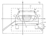
撮影装置31は、被写体を撮影することにより取得した画像を、電気信号に変換して出力する装置である。撮影装置31は、例えば図2に示されるように、自車両100のフロントウインド上部に取り付けられている。この撮影装置31は、自車両100の前方を撮影する。そして、撮影により取得した画像に関する画像情報を演算装置20へ出力する。
The photographing
図3は、自車両100と車両101との相対的な位置関係を示す図である。例えば、自車両100の前方を走行する車両101が、自車両100に相対的に接近している場合を考える。図3を参照するとわかるように、矢印a1に示される位置にある車両101は、所定の時間が経過すると矢印a2に示される位置に相対的に移動する。この場合には、撮影装置31によって、まず矢印a1に示される位置にある車両101が撮影され、次に矢印a2に示される位置にある車両101が撮影される。
FIG. 3 is a diagram illustrating a relative positional relationship between the
図4は、矢印a1に示される位置にある車両101を撮影することにより得られた画像PH1を示す図である。また、図5は、矢印a2に示される位置にある車両101を撮影することにより得られた画像PH2を示す図である。撮影装置31は、画像PH1,PH2に代表される画像PHを撮影すると、画像PHに関する情報を、演算装置20へ出力する。
Figure 4 is a diagram illustrating an image PH 1 obtained by photographing the
本実施形態では、上述の画像PHについて、撮影装置31の光学中心に対応する点(撮影装置31の光軸とその画像面との交点である画像中心)を原点Xc(FOE:Focus Of Expansion)とするxy座標系を定義する。このxy座標系の原点Xcは、画像PHの中心と一致する。
In the present embodiment, with respect to the above-described image PH, a point corresponding to the optical center of the image capturing device 31 (image center that is the intersection of the optical axis of the
図1に戻り、警報装置32は、演算装置20から出力される警報の発令指示を受信すると、自車両100のドライバに対して、例えば音声による警報を出力する。
Returning to FIG. 1, the
演算装置20は、CPU(Central Processing Unit)21、主記憶部22、補助記憶部23、表示部24、及びインターフェイス部26を有するコンピュータである。
The
CPU21は、補助記憶部23に記憶されているプログラムに従って、自車両100の周囲を走行する車両101を検出する。具体的な処理の内容については後述する。
The
主記憶部22は、RAM(Random Access Memory)等を有している。主記憶部22は、CPU21の作業領域として用いられる。
The
補助記憶部23は、例えばROM(Read Only Memory)、半導体メモリ等の不揮発性メモリを有している。補助記憶部23は、CPU21が実行するプログラム、及び各種パラメータなどを記憶している。また、撮影装置31から出力される画像に関する情報、及びCPU21による処理結果などを含む情報を順次記憶する。
The
表示部24は、LCD(Liquid Crystal Display)などの表示ユニットを有している。表示部24は、CPU21の処理結果等を表示する。
The
インターフェイス部26は、シリアルインターフェイスまたはLAN(Local Area Network)インターフェイス等を含んで構成されている。撮影装置31及び警報装置32は、インターフェイス部26を介してシステムバス27に接続される。
The
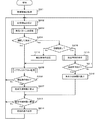
図9乃至図20のフローチャートは、CPU21によって実行されるプログラムの一連の処理アルゴリズムに対応している。以下、図面を参照しつつ、車両検出装置10の動作について説明する。なお、ここでは図4或いは図5を参照するとわかるように、撮影装置31の視野内に自車両100の前方を走行する車両101が位置しているものとする。
The flowcharts of FIGS. 9 to 20 correspond to a series of processing algorithms of a program executed by the
まず、最初のステップS201では、CPU21は、補助記憶部23に記憶された画像情報を取得する。ここでは、例えば図5に示される画像PH2に関する画像情報を取得する。
First, in first step S <b> 201, the
次のステップS202では、CPU21は、処理領域の設定を行うために、図10に示されるサブルーチンSR1を実行する。サブルーチンSR1の最初のステップS301では、CPU21は、ステップS201で取得した画像情報の直近に取得した画像情報によって規定される画像PHから、検出対象物が検出されているか否かを判断する。
In the next step S202, the
具体的には、CPU21は、画像PH2を規定する画像情報の前に取得された画像情報によって規定される画像PH1から、検出対象物が検出されている否かを判断する。画像PH1には、図4に示されるように、車両101が写っている。したがって、この車両101の画像が明瞭である場合には、画像PH1から車両101が検出される。この場合には、ステップS301での判断が肯定される(ステップS301:Yes)。一方、画像PH1に、車両101が写っていない場合や、画像が不明瞭である場合には、画像PH1からは、検出対象物が検出されない。この場合には、ステップS301での判断が否定される(ステップS301:No)。
Specifically,
ステップS301での判断が肯定された場合には(ステップS301:Yes)、CPU21は、ステップS302へ移行する。
If the determination in step S301 is affirmative (step S301: Yes), the
ステップS302では、CPU21は、検出領域の設定を行う。この検出領域の設定は、検出対象と自車両100との相対速度、画像PH上での検出対象の大きさに基づいて行われる。
In step S302, the
例えば、CPU21は、図4に示される画像PH1と、当該画像PH1が撮影される前に撮影された画像PH0によって規定される車両101のオプティカルフローに基づいて、車両101の相対速度を算出する。そして、車両101の相対速度と、画像PH1での車両101の画像の大きさに基づいて、図5に示されるように、画像PH2に、車両101の画像が現れると予測される領域A1を特定する。そして、CPU21は、領域A1を、画像PH2に写る車両101を検出するための検出領域に設定する。検出領域が設定された後は、この検出領域に対してのみ、検出対象物の検出処理が実行される。これにより、検出対象物の検出処理の際に行われる演算が少なくなる。
For example, the
また、ステップS301での判断が否定された場合は(ステップS301:No)、CPU21は、ステップS303へ移行する。
If the determination in step S301 is negative (step S301: No), the
ステップS303では、CPU21は、画像PHの全体を検出領域に設定する。これにより、検出対象物の検出処理は、画像全体に対して実行されることになる。
In step S303, the
ステップS302及びステップS303の処理が終了すると、CPU21は、サブルーチンSR1を終了し、次のステップS203へ移行する。
When the processes of step S302 and step S303 are completed, the
ステップS203では、CPU21は、車両パターンの探索を行うために、図11に示されるサブルーチンSR2を実行する。車両パターンとは、例えば、車両の輪郭、テールランプ、ヘッドランプ、車両の下にできる影、タイヤ、及びナンバープレートそれぞれを構成する画素群からなる部分画像をいう。これらは、車両101の画像を構成する。以下、車両の輪郭、テールランプ、ヘッドランプ、影、タイヤ、ナンバープレートに対応する車両パターンを、車両パターン1〜6と表示する。
In step S203, the
サブルーチンSR2の最初のステップS401では、CPU21は、演算順序の設定を行うために、図12に示されるサブルーチンSR3を実行する。
In the first step S401 of the subroutine SR2, the
サブルーチンSR3の最初のステップS501では、CPU21は、ステップS201で取得した画像情報の直近に取得した画像情報によって規定される画像PHから、車両パターンが検出されているか否かを判断する。
In the first step S501 of the subroutine SR3, the
具体的には、CPU21は、画像PH1から車両101を構成する車両パターンが検出されているか否かを判断する。画像PH1から、例えば、車両の輪郭、テールランプ、ヘッドランプ、車両の下にできる影、タイヤ、及びナンバープレートを示す車両パターンが検出されている場合には、ステップS501での判断が肯定される。一方、画像PH1から、車両パターンが検出されていない場合には、ステップS501での判断が否定される。
Specifically,
ステップS501での判断が肯定された場合には(ステップS501:Yes)、CPU21は、ステップS502へ移行する。
If the determination in step S501 is affirmative (step S501: Yes), the
ステップS502では、CPU21は、車両パターンの特徴量それぞれに基づいて、車両パターンをソートする。上述の特徴量は、後述するサブルーチンSR2のステップS402で算出される要素である。この特徴量は、車両パターンを構成する部分画像が、車両101の画像の一部であることを示す信頼度と等価である。
In step S502, the
そして、例えば、車両パターン1の信頼度が1、車両パターン2の信頼度が5、車両パターン3の信頼度が3、車両パターン4の信頼度が6、車両パターン5の信頼度が2、車両パターン6の信頼度が、7である場合には、ステップS502の処理によって、車両パターン6、車両パターン4、車両パターン2、車両パターン3、車両パターン5、車両パターン1の順に順位が付与される。 For example, the reliability of the vehicle pattern 1 is 1, the reliability of the vehicle pattern 2 is 5, the reliability of the vehicle pattern 3 is 3, the reliability of the vehicle pattern 4 is 6, the reliability of the vehicle pattern 5 is 2, and the vehicle When the reliability of the pattern 6 is 7, the rank is given in the order of the vehicle pattern 6, the vehicle pattern 4, the vehicle pattern 2, the vehicle pattern 3, the vehicle pattern 5, and the vehicle pattern 1 by the process of step S502. .
次のステップS503では、CPU21は、車両パターンについての特徴量を算出する順番を設定する。例えば、ステップS502で、各車両パターン1〜6それぞれに、車両パターン6、車両パターン4、車両パターン2、車両パターン3、車両パターン5、車両パターン1の順に順位が付与された場合には、この順位にしたがった順番を設定する。これにより、前回算出された信頼度が高い車両パターンから順に、当該車両パターンの特徴量が算出されることになる。
In the next step S503, the
一方、ステップS501での判断が否定された場合には(ステップS501:No)、CPU21は、ステップS504へ移行する。
On the other hand, when the determination in step S501 is negative (step S501: No), the
ステップS504では、CPU21は、今現在が夜間であるか否かを判断する。この判断は、画像の特定領域の平均輝度を計算し、その輝度が所定の閾値を下回るか否かにより行う。特定領域の平均輝度が、閾値を下回った場合には、今現在が夜間であると判断することができる。
In step S504, the
ステップS504での判断が否定された場合には(ステップS504:No)、CPU21は、ステップS505へ移行する。
If the determination in step S504 is negative (step S504: No), the
ステップS505では、CPU21は、車両パターンの特徴量を算出するときの順番を、昼間に適した順番に設定する。車両101の画像を構成する各車両パターンは、昼間に容易に検出できるものと、夜間に容易に検出できるものがあり、車両101の周囲環境によって、検出容易性が変化する。
In step S505, the
そこで、昼間に検出容易性が高い車両パターンから順に、当該車両パターンに予め順位を付与しておく。そして、ステップS505では、予め付与された順位にしたがって、車両パターンについての特徴量を算出する順番を設定する。これにより、後述するステップS402において、昼間に検出容易性が高い車両パターンから順に、当該車両パターンの特徴量が算出されることになる。 Therefore, in order from the vehicle pattern that is easy to detect in the daytime, a rank is assigned to the vehicle pattern in advance. In step S505, the order of calculating the feature values for the vehicle pattern is set in accordance with the order given in advance. As a result, in step S402, which will be described later, the feature amount of the vehicle pattern is calculated in order from the vehicle pattern that is easy to detect in the daytime.
一方、ステップS504での判断が肯定された場合には(ステップS504:Yes)、CPU21は、ステップS506へ移行する。
On the other hand, when the determination in step S504 is affirmed (step S504: Yes), the
ステップS506では、CPU21は、車両パターンの特徴量を算出するときの順番を、夜間に適した順番に設定する。具体的には、夜間に検出容易性が高い車両パターンから順に、当該車両パターンに予め順位を付与しておく。そして、ステップS506では、予め付与された順位にしたがって、車両パターンについての特徴量を算出する順番を設定する。これにより、後述するステップS402において、夜間に検出容易性が高い車両パターンから順に、当該車両パターンの特徴量が算出されることになる。
In step S506, the
ステップS503,ステップS505,又はステップS506の処理が終了すると、CPU21は、サブルーチンSR3を終了し、サブルーチンSR2のステップS402へ移行する。
When the process of step S503, step S505, or step S506 ends, the
次のステップS402では、ステップS401で設定された順番にしたがって、車両パターンそれぞれの特徴量を算出する。以下、各車両パターンの特徴量の算出を、図13乃至図18に示されるサブルーチンSR4〜SR9を参照しつつ説明する。 In the next step S402, the feature amount of each vehicle pattern is calculated according to the order set in step S401. Hereinafter, calculation of the feature amount of each vehicle pattern will be described with reference to subroutines SR4 to SR9 shown in FIGS.
《車両輪郭候補の特徴量算出》
図13は、車両輪郭候補の特徴量を算出するための手順を示すサブルーチンSR4である。図13に示されるように、最初のステップS601では、CPU21は、特徴量の算出が既にされているか否かを判断する。例えば、画像PH1について、図13に示されるステップS601〜S611までの処理が実行されている場合には、画像PH2についてのステップS601での判断が肯定され(ステップS601:Yes)、CPU21は、ステップS602へ移行する。一方、画像PH1について、図13に示されるステップS601〜S611までの処理が実行されていない場合には、画像PH2についてのステップS601での判断が否定され(ステップS601:No)、CPU21は、ステップS603へ移行する。
《Feature calculation of vehicle contour candidates》
FIG. 13 is a subroutine SR4 showing a procedure for calculating the feature amount of the vehicle contour candidate. As shown in FIG. 13, in the first step S601, the
ステップS602では、CPU21は、検出領域を制限する。図5に示されるように、検出領域としての領域A1は、画像PHに写る車両101の画像を含む領域に設定されている。そこで、CPU21は、ステップS601で、車両101の輪郭が検出されている場合には、この輪郭に基づいて、検出領域を制限する。これにより、図6に示されるように、車両101の輪郭を示すボディのエッジに基づいて、領域A1の中に、検出領域としての領域A2が規定される。
In step S602, the
ステップS603では、CPU21は、領域A2に含まれる画素それぞれに対して、例えばソーベルフィルタを用いた演算を行うことにより、画素それぞれについての微分値を算出する。
In step S603, the
次のステップS604では、CPU21は、エッジの抽出を行う。例えばCPU21は、画素それぞれの微分値を二値化する。そして、二値化された微分値(以下エッジ値という)が1となる画素をエッジ点として抽出する。
In the next step S604, the
次のステップS605では、CPU21は、エッジ点を中心に水平方向に並ぶ画素の微分値のヒストグラムと、エッジ点を中心に垂直方向に並ぶ画素の微分値のヒストグラムとを算出する。
In the next step S605, the
次のステップS606では、CPU21は、算出したヒストグラムのピークから、値が閾値以上となるピークを抽出する。そして、ピークが現れた画像上の領域に対して、直線上に連続して並んだエッジ点の集合を水平線分或いは垂直線分として抽出する。
In the next step S606, the
次のステップS607では、CPU21は、車両輪郭候補を抽出する。例えば、CPU21は、各水平線分及び垂直成分を組み合わせる。そして、組み合わせた線分の数及び、組み合わせた線分の縦横比に基づいて、車両輪郭候補としてのエッジの集合を抽出する。
In the next step S607, the
次のステップS608では、CPU21は、車両輪郭候補の線分の数、線分を構成するエッジ点の微分値の平均値、車両輪郭候補の縦横比、及び、車両輪郭候補の下限位置と幅を、実際の車両が写る基準画像から抽出した特徴量と比較して、車両輪郭候補の信頼度を算出する。この信頼度は、車両輪郭候補としてのエッジの集合が、車両101のエッジである確度と等価である。
In the next step S608, the
次のステップS609では、CPU21は、ステップS608で算出した信頼度が、閾値より大きいか否かを判断する。CPU21は、信頼度が閾値より大きいと判断した場合には(ステップS609:Yes)、ステップS610に移行する。また、信頼度が閾値以下であると判断した場合には(ステップS609:No)、サブルーチンSR4を終了する。
In the next step S609, the
ステップS610では、CPU21は、画像PHに設定された検出領域に、車両輪郭の候補が存在すると認識する。これにより、次回のステップS601での判断が、肯定されることになる。そして、次のステップS611で、画像PH上での車両輪郭の位値と、幅、及び高さを記憶する。CPU21は、ステップS611の処理が終了すると、サブルーチンSR4を終了する。
In step S610, the
《テールランプ候補の特徴量算出》
図14は、テールランプ候補の特徴量を算出するための手順を示すサブルーチンSR5である。図14に示されるように、最初のステップS701では、CPU21は、特徴量の算出が既にされているか否かを判断する。例えば、画像PH1について、図14に示されるステップS701〜S710までの処理が実行されている場合には、画像PH2についてのステップS701での判断が肯定され(ステップS701:Yes)、CPU21は、ステップS702へ移行する。一方、画像PH1について、図14に示されるステップS701〜S710までの処理が実行されていない場合には、画像PH2についてのステップS701での判断が否定され(ステップS701:No)、CPU21は、ステップS703へ移行する。
<< Calculation of tail lamp candidate features >>
FIG. 14 is a subroutine SR5 showing a procedure for calculating the feature amount of the tail lamp candidate. As shown in FIG. 14, in the first step S701, the
ステップS702では、CPU21は、検出領域を制限する。図5に示されるように、検出領域としての領域A1は、画像PHに写る車両101の画像を含む領域である。そこで、CPU21は、ステップS701で、車両101のテールランプの部分画像が検出されている場合には、当該テールランプの部分画像に基づいて、検出領域を制限する。
In step S702, the
ステップS703では、CPU21は、検出領域から、赤色の画素を抽出する。例えば、CPU21は、各画素のHSV値(H:Hue, S:Saturation・Chroma, V:Brightness・Lightness・Value)を算出する。そして、CPU21は、各画素について算出したHSV値と、実際のテールランプの画像を構成する画素のHSV値との差を算出し、その差が所定の範囲内にある画素を抽出する。これにより、画像PHから色相が赤の画素が順次抽出され、結果的に、赤色の画素からなる画素群が抽出される。
In step S703, the
次のステップS704では、CPU21は、抽出された画素群から、面積が所定の基準値よりも大きい領域を形成する画素群を抽出する。そして、抽出した画素群を構成する画素にラベリングを施す。これにより、画素群それぞれが、1つの赤色領域として認識される。
In the next step S704, the
次のステップS705では、CPU21は、赤色領域についての特徴量を抽出する。例えば、CPU21は、赤色領域の縦横比及び円形度、赤色領域を構成する画素の色相の平均値、基準色に対する赤色比率、1組のテールランプの候補としての1組の赤色領域の対称性等に代表される特徴量を算出する。
In the next step S705, the
次のステップS706では、CPU21は、ステップS705で抽出した特徴量に基づいて、テールランプの部分画像の候補となる赤色領域を抽出する。
In the next step S706, the
次のステップS707では、CPU21は、ステップS706で抽出した赤色領域と、実際のテールランプを写した基準画像から抽出した特徴量とを比較して、候補としての赤色領域が、テールランプの部分画像である確度と等価な信頼度を算出する。
In the next step S707, the
次のステップS708では、CPU21は、ステップS707で算出した信頼度が、閾値より大きいか否かを判断する。CPU21は、信頼度が閾値より大きいと判断した場合には(ステップS708:Yes)、ステップS709に移行する。一方、信頼度が閾値以下であると判断した場合には(ステップS708:No)、サブルーチンSR5を終了する。
In the next step S708, the
ステップS709では、CPU21は、画像PHに設定された検出領域に、テールランプの候補となる赤色領域が存在すると認識する。これにより、次回のステップS701での判断が、肯定されることになる。そして、次のステップS710で、画像PH上での、テールランプの候補となる赤色領域同士の間隔及び位置を記憶する。CPU21は、ステップS710の処理が終了すると、サブルーチンSR5を終了する。
In step S709, the
《ヘッドランプ候補の特徴量算出》
図15は、ヘッドランプ候補の特徴量を算出するための手順を示すサブルーチンSR6である。図15に示されるように、最初のステップS801では、CPU21は、特徴量の算出が既にされているか否かを判断する。例えば、画像PH1について、図15に示されるステップS801〜S810までの処理が実行されている場合には、画像PH2についてのステップS801での判断が肯定され(ステップS801:Yes)、CPU21は、ステップS802へ移行する。一方、画像PH1について、図15に示されるステップS801〜S810までの処理が実行されていない場合には、画像PH2についてのステップS801での判断が否定され(ステップS801:No)、CPU21は、ステップS803へ移行する。
《Feature calculation of headlamp candidate》
FIG. 15 is a subroutine SR6 showing a procedure for calculating the feature amount of the headlamp candidate. As shown in FIG. 15, in the first step S801, the
ステップS802では、CPU21は、検出領域を制限する。図5に示されるように、検出領域としての領域A1は、画像PHに写る車両101の画像を含む領域に設定されている。そこで、CPU21は、ステップS801で、車両101のヘッドランプの部分画像が検出されている場合には、当該ヘッドランプの部分画像に基づいて、検出領域を制限する。
In step S802, the
ステップS803では、CPU21は、検出領域から、白色の画素からある白色領域を抽出する。例えば、CPU21は、各画素のHSV値を算出する。そして、CPU21は、各画素について算出したHSV値と、実際のヘッドランプの画像を構成する画素のHSV値との差を算出し、その差が所定の範囲内にある画素を抽出する。これにより、画像PHから色相が白の画素が順次抽出され、結果的に、白色の画素からなる画素群が抽出される。
In step S <b> 803, the
次のステップS804では、CPU21は、抽出された画素群から、面積が所定の基準値よりも大きい領域を形成する画素群を抽出する。そして、抽出した画素群を構成する画素にラベリングを施す。これにより、画素群それぞれが、1つの白色領域として認識される。
In the next step S804, the
次のステップS805では、CPU21は、白色領域についての特徴量を抽出する。例えば、CPU21は、白色領域の縦横比、円形度、白色領域を構成する画素の色相の平均値、基準色に対する白色比率、1組のヘッドランプの候補としての1組の白色領域の対称性等に代表される特徴量を算出する。
In the next step S805, the
次のステップS806では、CPU21は、ステップS805で抽出した特徴量から、ヘッドランプの画像の候補となる白色領域を抽出する。
In the next step S806, the
次のステップS807では、CPU21は、ステップS806で抽出した白色領域と、実際のヘッドランプを写した基準画像から抽出した特徴量とを比較して、候補としての白色領域が、ヘッドランプの画像である確度と等価な信頼度を算出する。
In the next step S807, the
次のステップS808では、CPU21は、ステップS807で算出した信頼度が、閾値より大きいか否かを判断する。CPU21は、信頼度が閾値より大きいと判断した場合には(ステップS808:Yes)、ステップS809に移行する。また、信頼度が閾値以下であると判断した場合には(ステップS808:No)、サブルーチンSR6を終了する。
In the next step S808, the
ステップS809では、CPU21は、画像PHに設定された検出領域に、ヘッドランプの候補となる白色領域が存在すると認識する。これにより、次回のステップS801での判断が、肯定されることになる。そして、次のステップS810で、画像PH上での、ヘッドランプの候補となる白色領域同士の間隔及び位置を記憶する。CPU21は、ステップS810の処理が終了すると、サブルーチンSR6を終了する。
In step S809, the
《車両下影候補の特徴量算出》
図16は、車両下影候補の特徴量を算出するための手順を示すサブルーチンSR7である。図16に示されるように、最初のステップS901では、CPU21は、特徴量の算出が既にされているか否かを判断する。例えば、画像PH1について、図16に示されるステップS901〜S912までの処理が実行されている場合には、画像PH2についてのステップS901での判断が肯定され(ステップS901:Yes)、CPU21は、ステップS902へ移行する。一方、画像PH1について、図16に示されるステップS901〜S912までの処理が実行されていない場合には、画像PH2についてのステップS901での判断が否定され(ステップS901:No)、CPU21は、ステップS903へ移行する。
《Calculating feature value of vehicle shadow candidate》
FIG. 16 is a subroutine SR7 showing a procedure for calculating the feature amount of the vehicle lower shadow candidate. As shown in FIG. 16, in the first step S901, the
ステップS902では、CPU21は、検出領域を制限する。図5に示されるように、検出領域としての領域A1は、画像PHに写る車両101の画像を含む領域に設定されている。そこで、CPU21は、ステップS901で、車両101の下の影の部分画像が検出されている場合には、部分画像に基づいて、検出領域を制限する。
In step S902, the
ステップS903では、CPU21は、検出領域に含まれる画素それぞれに対して、例えばソーベルフィルタを用いた演算を行うことにより、画素それぞれについての微分値を算出する。
In step S903, the
次のステップS904では、CPU21は、エッジの抽出を行う。例えばCPU21は、画素それぞれの微分値を二値化する。そして、二値化された微分値(以下エッジ値という)が1となる画素をエッジ点として抽出する。
In the next step S904, the
次のステップS905では、CPU21は、エッジ点を中心に水平方向に並ぶ画素の微分値のヒストグラムと、エッジ点を中心に垂直方向に並ぶ画素の微分値のヒストグラムとを算出する。
In the next step S905, the
次のステップS906では、CPU21は、算出したヒストグラムのピークに対応したエッジ点を抽出し、微分値の符合が相互に異なるエッジ点同士を、1組のエッジ点として順次抽出する。これにより、画像PHから低輝度画素で示される影の画像のエッジが順次抽出される。
In the next step S906, the
次のステップS907では、CPU21は、ステップS906で抽出されたエッジ点によって包囲される領域(以下、包囲領域という)の総面積に対する、輝度が所定の値以下の画素からなる低輝度領域の面積の割合(面積比)を算出する。
In the next step S907, the
次のステップS908では、CPU21は、包囲領域が複数有る場合には、面積比が最も大きくなるときの包囲領域を、影の部分画像の候補となる領域として抽出する。また、包囲領域が1つしかない場合には、ステップS907で算出した面積比が、所定の値以上である場合に、当該包囲領域を、影の部分画像の候補となる領域として抽出する。
In the next step S908, when there are a plurality of surrounding areas, the
次のステップS909では、CPU21は、面積比率、包囲領域を構成する画素の輝度の平均値、及び包囲領域の縦横比を、実際の影が写る基準画像から抽出した特徴量と比較して、候補としての包囲領域が、車両101の影の部分画像である確度と等価な信頼度を算出する。
In the next step S909, the
次のステップS910では、CPU21は、ステップS909で算出した信頼度が、閾値より大きいか否かを判断する。CPU21は、信頼度が閾値より大きいと判断した場合には(ステップS910:Yes)、ステップS911に移行する。また、信頼度が閾値以下であると判断した場合には(ステップS910:No)、サブルーチンSR7を終了する。
In the next step S910, the
ステップS911では、CPU21は、画像PHに設定された検出領域に、車両の影の候補が存在すると認識する。これにより、次回のステップS901での判断が、肯定されることになる。そして、次のステップS912で、画像PH上での包囲領域の位値、及び幅を記憶する。CPU21は、ステップS912の処理が終了すると、サブルーチンSR7を終了する。
In step S911, the
《タイヤ候補の特徴量算出》
図17は、タイヤ候補の特徴量を算出するための手順を示すサブルーチンSR8である。図17に示されるように、最初のステップS1001では、CPU21は、特徴量の算出が既にされているか否かを判断する。例えば、画像PH1について、図17に示されるステップS1001〜S1012までの処理が実行されている場合には、画像PH2についてのステップS1001での判断が肯定され(ステップS1001:Yes)、CPU21は、ステップS1002へ移行する。一方、画像PH1について、図17に示されるステップS1001〜S1012までの処理が実行されていない場合には、画像PH2についてのステップS1001での判断が否定され(ステップS1001:No)、CPU21は、ステップS1003へ移行する。
《Calculation of tire candidate features》
FIG. 17 is a subroutine SR8 showing a procedure for calculating the feature amount of the tire candidate. As shown in FIG. 17, in the first step S1001, the
ステップS1002では、CPU21は、検出領域を制限する。図5に示されるように、検出領域としての領域A1は、画像PHに写る車両101の画像を含む領域に設定されている。そこで、CPU21は、ステップS1001で、車両101のタイヤの部分画像が検出されている場合には、部分画像に基づいて、検出領域を制限する。
In step S1002, the
ステップS1003では、CPU21は、検出領域に含まれる画素それぞれに対して、例えばソーベルフィルタを用いた演算を行うことにより、画素それぞれについての微分値を算出する。
In step S1003, the
次のステップS1004では、CPU21は、エッジの抽出を行う。例えばCPU21は、画素それぞれの微分値を二値化する。そして、二値化された微分値(以下エッジ値という)が1となる画素をエッジ点として抽出する。
In the next step S1004, the
次のステップS1005では、CPU21は、エッジ点を中心に水平方向に並ぶ画素の微分値のヒストグラムと、エッジ点を中心に垂直方向に並ぶ画素の微分値のヒストグラムとを算出する。
In the next step S1005, the
次のステップS1006では、CPU21は、算出したヒストグラムのピークに対応したエッジ点を抽出し、微分値の符合が相互に異なるエッジ点同士を、1組のエッジ点として順次抽出する。これにより、画像PHから低輝度画素で示されるタイヤの画像のエッジが順次抽出される。
In the next step S1006, the
次のステップS1007では、CPU21は、ステップS1006で抽出されたエッジ点によって包囲される領域(包囲領域)の総面積に対する、輝度が所定の値以下の画素からなる低輝度領域の面積の割合(面積比)を算出する。
In the next step S1007, the
次のステップS1008では、CPU21は、ステップS1007で算出した面積比が、所定の値以上である矩形状の包囲領域を、タイヤの部分画像の候補となる領域として抽出する。
In the next step S1008, the
次のステップS1009では、CPU21は、包囲領域の高さ、幅を、実際のタイヤが写る基準画像から抽出した特徴量と比較して、候補としての包囲領域が、車両101のタイヤの部分画像である確度と等価な信頼度を算出する。また、その際には、1組の包囲領域が候補として抽出されたときは、包囲領域同士の間隔や、対称性、類似性も考慮する。
In the next step S1009, the
次のステップS1010では、CPU21は、ステップS1009で算出した信頼度が、閾値より大きいか否かを判断する。CPU21は、信頼度が閾値より大きいと判断した場合には(ステップS1010:Yes)、ステップS1011に移行する。また、信頼度が閾値以下であると判断した場合には(ステップS1010:No)、サブルーチンSR8を終了する。
In the next step S1010, the
ステップS1011では、CPU21は、画像PHに設定された検出領域に、車両のタイヤの候補が存在すると認識する。これにより、次回のステップS1001での判断が、肯定されることになる。そして、次のステップS1012で、画像PH上での包囲領域相互間の間隔、位値、及び幅を記憶する。CPU21は、ステップS1012の処理が終了すると、サブルーチンSR8を終了する。
In step S1011, the
《ナンバープレート候補の特徴量算出》
図18は、ナンバープレート候補の特徴量を算出するための手順を示すサブルーチンSR9である。図18に示されるように、最初のステップS1101では、CPU21は、特徴量の算出が既にされているか否かを判断する。例えば、画像PH1について、図18に示されるステップS1101〜S1112までの処理が実行されている場合には、画像PH2についてのステップS1101での判断が肯定され(ステップS1101:Yes)、CPU21は、ステップS1102へ移行する。一方、画像PH1について、図18に示されるステップS1101〜S1112までの処理が実行されていない場合には、画像PH2についてのステップS1101での判断が否定され(ステップS1101:No)、CPU21は、ステップS1103へ移行する。
<Calculation of license plate candidate features>
FIG. 18 is a subroutine SR9 showing a procedure for calculating the feature amount of the license plate candidate. As shown in FIG. 18, in the first step S1101, the
ステップS1102では、CPU21は、検出領域を制限する。図5に示されるように、検出領域としての領域A1は、画像PHに写る車両101の画像を含む領域に設定されている。そこで、CPU21は、ステップS1101で、車両101のナンバープレートの部分画像が検出されている場合には、部分画像に基づいて、検出領域を制限する。
In step S1102, the
ステップS1103では、CPU21は、検出領域に含まれる画素それぞれに対して、例えばソーベルフィルタを用いた演算を行うことにより、画素それぞれについての微分値を算出する。
In step S1103, the
次のステップS1104では、CPU21は、エッジの抽出を行う。例えばCPU21は、画素それぞれの微分値を二値化する。そして、二値化された微分値(以下エッジ値という)が1となる画素をエッジ点として抽出する。
In the next step S1104, the
次のステップS1105では、CPU21は、エッジ点を中心に水平方向に並ぶ画素の微分値のヒストグラムと、エッジ点を中心に垂直方向に並ぶ画素の微分値のヒストグラムとを算出する。
In the next step S <b> 1105, the
ナンバープレートは、規定によりその大きさ及び形状が決まっており、縦横比は一定の値になる。そこで、次のステップS1106では、CPU21は、算出したヒストグラムのピークに対応したエッジ点を抽出し、微分値の符合が相互に異なるエッジ点同士を1組となったエッジ点として順次抽出する。そして、1組のエッジ点によって形成されるエッジのうち、縦横比率がナンバープレートの縦横比率とほぼ等価なエッジを、画像PHからナンバープレートのエッジとして抽出する。これにより、長方形枠状のエッジが抽出される。ここで、車両の輪郭を示すエッジが検出されている場合には、長方形枠状のエッジと、車両の輪郭との大きさを比較して、信頼性の高いエッジのみを抽出することとしてもよい。
The size and shape of the license plate are determined by regulations, and the aspect ratio is a constant value. Therefore, in the next step S1106, the
次のステップS1107では、CPU21は、ステップS1106で抽出されたエッジによって包囲される領域(包囲領域)の画素それぞれについて、色相値を算出する。そして、ナンバープレートの背景色と色相が等価な白の画素と、ナンバープレートの文字の色と色相が等価の緑の画素とを抽出する。そして、白の画素が占める面積に対する、緑の画素が占める面積の面積比率を算出する。
In the next step S1107, the
次のステップS1108では、ステップS1107で算出した面積比率が一定以上の包囲領域を、ナンバープレートの部分画像の候補となる領域として抽出する。 In the next step S1108, the surrounding area having a certain area ratio or more calculated in step S1107 is extracted as a candidate area for the license plate partial image.
次のステップS1109では、CPU21は、包囲領域の高さ、幅、縦横比、面積比率を、実際のナンバープレートが写る基準画像から抽出した特徴量と比較して、候補としての包囲領域が、車両101のナンバープレートの部分画像である確度と等価な信頼度を算出する。
In the next step S1109, the
次のステップS1110では、CPU21は、ステップS1109で算出した信頼度が、閾値より大きいか否かを判断する。CPU21は、信頼度が閾値より大きいと判断した場合には(ステップS1110:Yes)、ステップS1111に移行する。また、信頼度が閾値以下であると判断した場合には(ステップS1110:No)、サブルーチンSR9を終了する。
In the next step S1110, the
ステップS1111では、CPU21は、画像PHに設定された検出領域に、車両のタイヤの候補が存在すると認識する。これにより、次回のステップS1101での判断が、肯定されることになる。そして、次のステップS1112で、画像PH上での包囲領域の幅、高さ及び位置を記憶する。CPU21は、ステップS1112の処理が終了すると、サブルーチンSR9を終了する。
In step S <b> 1111, the
CPU21は、サブルーチンSR2のステップS402の処理で、上述した車両の輪郭、テールランプ、ヘッドランプ、影、タイヤ、ナンバープレートのうちのいずれかを、ステップS401で規定された順番に基づいて選択して特徴量を算出する。例えば、ステップS401で規定された順番が、車両の輪郭、テールランプ、ヘッドランプ、影、タイヤ、ナンバープレートの順である場合には、CPU21は、ステップS405の処理の後ステップS402の処理が繰り返されるたびに、まず1回目のステップS402の処理で、車両の輪郭候補の特徴量を算出し、2回目のステップS402の処理で、テールランプ候補の特徴量を算出し、移行順次ステップS401で規定された順番に基づいて特徴量を算出する。ステップS402の処理が終了すると、CPU21は、ステップS403へ移行する。
In step S402 of subroutine SR2, the
ステップS403では、CPU21は、認識信頼度を算出する。具体的には、CPU21は、サブルーチンSR4〜SR9の処理を実行することにより算出した信頼度の確率和を、認識信頼度として算出する。例えば、N回目のステップS402で実行されたサブルーチンによって算出された信頼度をrNとすると、認識信頼度Rは次式(1)で示される。
In step S403, the
R=1−(1−r1)・(1−r2)・…・(1−rN) …(1) R = 1- (1-r 1 ) · (1-r 2 ) ···· (1-r N ) (1)
次のステップS404では、CPU21は、ステップS403で算出された認識信頼度が、閾値よりも大きいか否かを判断する。認識信頼度が閾値以下であると判断された場合には(ステップS404:No)、CPU21は、次のステップS405へ移行する。
In the next step S404, the
ステップS405では、CPU21は、すべての車両パターンについての特徴量を算出したか否かを判断する。例えば、上述した車両の輪郭、テールランプ、ヘッドランプ、影、タイヤ、ナンバープレートすべてについての特徴量が算出されている場合には、CPU21は、サブルーチンSR2の処理を終了して、次のステップS204へ移行する。一方、特徴量が算出されていない車両パターンがある場合には(ステップS405:No)、ステップS401へ戻り、ステップS401以降の処理を実行する。
In step S405, the
また、ステップS404で、認識信頼度が閾値よりも大きいと判断された場合には(ステップS404:Yes)、CPU21は、ステップS406へ移行する。
If it is determined in step S404 that the recognition reliability is greater than the threshold (step S404: Yes), the
ステップS406では、CPU21は、認識信頼度を補助記憶部23へ記憶する。ステップS406の処理を終了すると、CPU21は、サブルーチンSR2の処理を終了して、ステップS204へ移行する。
In step S <b> 406, the
ステップS204では、ステップS203の処理を行うことで、信頼性の高い認識信頼度を、連続して算出することができたか否かを判断する。信頼性が高いか否かの判断は、認識信頼度がステップS404での閾値以上であるか否かによって行う。そして、ステップS203が繰り返し実行されることで、信頼性の高い認識信頼度が連続して算出された場合には、ステップS204での判断が肯定される。一方、信頼性の高い認識信頼度が連続して算出されなかった場合には、ステップS204での判断が否定される。 In step S204, it is determined whether or not the recognition reliability with high reliability has been continuously calculated by performing the processing in step S203. Whether or not the reliability is high is determined based on whether or not the recognition reliability is equal to or higher than the threshold value in step S404. Then, when step S203 is repeatedly executed and a highly reliable recognition reliability is continuously calculated, the determination in step S204 is affirmed. On the other hand, when the highly reliable recognition reliability is not continuously calculated, the determination in step S204 is denied.
図9に示されるステップS202〜S214までの処理は繰り返し実行されるが、ステップS204での処理が初めて実行される場合には、ここでの判断は否定され(ステップS204:No)、CPU21は、ステップS205へ移行する。
The processing from step S202 to S214 shown in FIG. 9 is repeatedly executed. However, when the processing in step S204 is executed for the first time, the determination here is negative (step S204: No), and the
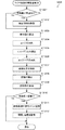
ステップS205では、CPU21は、図19に示されるサブルーチンSR10を実行する。サブルーチンSR10の最初のステップS1201では、CPU21は、補助記憶部23に記憶された画像PH1,PH2を構成する画素それぞれについての特徴量を算出し、この特徴量に基づいて画像に含まれる特徴点を抽出する。図4に示されるように、ここでは画像PH1について、特徴点P1,P2,P3,P4が抽出される。また、図5に示されるように、画像PH2について、特徴点Q1,Q2,Q3,Q4が抽出される。
In step S205, the
次のステップS1202では、CPU21は、画像PH1の特徴点P1〜P4を順次選択する。そして、この選択した特徴点と、画像PH2の特徴点Q1〜Q4の相関値を算出する。例えば、CPU21は、まず画像PH1の特徴点P1を中心とするテンプレートTF1を、画像PH2の特徴点Q1〜Q4の近傍で移動させながら、画像PH2に対するテンプレートTF1の相関値Rを順次算出する。CPU21は、上述の処理を、特徴点P2〜P4についても行う。
In the next step S1202,
次のステップS1203では、CPU21は、図7を参照するとわかるように、算出した相関値Rに基づいて、画像PH1の特徴点P1〜P4を始点とし、画像PH2の特徴点Q1〜Q4を終点とするオプティカルフローOP1〜OP4を規定する。
In the next step S1203,
次のステップS1204では、CPU21は、規定された1群のオプティカルフローのグルーピングを行う。図7に示されるように、本実施形態では説明の便宜上、車両101に関するオプティカルフローが4本である場合について説明している。しかしながら、実際は、車両101を撮影した画像からは、数十或いは数百の特徴点を抽出することができる。そして、数十或いは数百本のオプティカルフローを規定することができる。
In the next step S1204, the
CPU21は、数十或いは数百本のオプティカルフローのうちから、ノイズ成分を多く含むオプティカルフローを除外し、残りのオプティカルフローをグルーピングする。例えば、車両101が完全な直線運動をしている場合には、各オプティカルフローと一致する直線は消失点VPで交わるはずである。そこで、CPU21は、オプティカルフローと一致する直線が、消失点VPから著しく離れている場合には、このオプティカルフローを除外し、残りのオプティカルフローを同一の移動体に関連するオプティカルフローとみなしてグルーピングする。ここでは車両101に関するオプティカルフローOP1〜OP4が、車両101のオプティカルフローとしてグルーピングされる。ステップS1204の処理が終了すると、CPU21は、ステップS206へ移行する。
The
ステップS206では、CPU21は、グルーピングされたオプティカルフローに基づいて、自車両100に接近する物体があるか否かを判断する。例えば、図7に示されるように、グルーピングされたオプティカルフローが、消失点VPから離れる方向を向いている場合は、CPU21は、自車両100に接近する物体があると判断する。一方、グルーピングされたオプティカルフローが、消失点VPに近づく方向を向いている場合は、CPU21は、自車両100に接近する物体がないと判断する。
In step S206, the
CPU21は、自車両100に接近する物体がないと判断した場合には(ステップS206:No)、ステップS202へ戻り、ステップS202以降の処理を実行する。また、CPU21は、自車両100に接近する物体があると判断した場合には(ステップS206:Yes)、ステップS207へ移行する。
When the
ステップS207では、CPU21は、オプティカルフローOP1〜OP4を用いて、車両101が自車両100に衝突するまでの衝突予測時間TTCを算出する。
In step S207, the
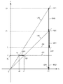
画像PH1が撮影されたときに、例えば図3における矢印a1に示される位置にある車両101は、画像PH2が撮影されたときには、図3における矢印a2に示される位置に相対的に移動している。この場合、図8に示されるように、特徴点P1を始点とし、特徴点Q1を終点とするオプティカルフローOP1に対応するXYZ座標系でのベクトルは、始点を対応点RP1とし、終点を対応点RQ1とするベクトルMV0となる。
When the image PH 1 is captured, the
オプティカルフローOP1は、撮影装置31の画像面IM(図3参照)内における特徴点の移動軌跡を示している。そして、ベクトルMV0は、XYZ座標系における対応点の移動軌跡を示している。本実施形態では、車両101は、Z軸に平行に相対移動するため、ベクトルMV0はZ軸に平行となる。また、特徴点P1及び対応点RP1は、XYZ座標系において原点Oを通る直線LN3上に配置されている。そして、特徴点Q1及び対応点RQ1は、XYZ座標系において原点Oを通る直線LN4上に配置されている。
The optical flow OP1 shows the movement locus of the feature points in the image plane IM (see FIG. 3) of the
したがって、対応点RQ1と一致している車両101の指標点が、X座標をX1とするX軸上の点CP1に到達するまでの軌跡を示すベクトルMV2の大きさ|MV2|と、特徴点P1のX座標x2と、特徴点Q1のX座標x1と、ベクトルMV0の大きさ|MV0|との幾何学的な関係は、次式(2)で示される。
Accordingly, the magnitude | MV2 | of the vector MV2 indicating the trajectory until the index point of the

ここで、ベクトルMV0の大きさ|MV0|は、画像PH1が撮像された時刻から画像PH2が撮像された時刻までの時間Δtと、自車両100に対する車両101の相対速度Vとの積(=V・Δt)である。また、ベクトルMV2の大きさ|MV2|は、指標点が対応点RQ1からX軸上の点CP1まで移動するのに要する時間TTCcと、相対速度Vとの積(=V・TTCc)である。
Here, the magnitude of the vector MV0 | MV0 | is the time Δt from the time that the image PH 1 is captured until the time that the image PH 2 is imaged, the product of the relative velocity V of the
そこで、上記式(2)の|MV2|に(V・TTCc)を代入し、|MV0|に(V・Δt)を代入して、両辺を相対速度Vで除することで、次式(3)が得られる。 Therefore, by substituting (V · TTCc) for | MV2 | in the above equation (2), substituting (V · Δt) for | MV0 |, and dividing both sides by the relative velocity V, the following equation (3 ) Is obtained.
また、車両101の指標点が、対応点RQ1から直線LN2で示される衝突面上の点CP2に到達するまでの軌跡を示すベクトルMV1は、Z軸と平行である。そして、ベクトルMV1の大きさ|MV1|とベクトルMV2の大きさ|MV2|との関係は、X軸から対応点RQ1までの距離Z1と、X軸と点CP2までの距離Lを用いると、次式(4)で示される。そして、次式(4)の|MV2|に(V・TTCc)を代入し、|MV1|に(V・TTC)を代入して、両辺を相対速度Vで除することで、相対速度Vを含む項を含まない次式(5)が得られる。
Further, vector MV1 indicating the trajectory until the index point of
上記式(5)のLは、X軸と直線LN2で示される衝突面との距離であり、撮影装置31の取り付け位置と自車両100の前端との距離にほぼ等しい既知の値である。このため、CPU21は、X軸と対応点RQ1との距離Z1の値がわかれば、上記式(5)を用いて、車両101が自車両100に衝突するまでの衝突予測時間TTCを算出することが可能となる。
L in the above equation (5) is the distance between the X axis and the collision surface indicated by the straight line LN2, and is a known value that is substantially equal to the distance between the mounting position of the photographing
そこで、CPU21は、次式(6)を用いて距離Z1を算出する。そして、算出した距離Z1を、上記式(5)に代入して、衝突予測時間TTCを算出する。なお、fは撮影装置31の焦点距離である。また、δは、画像PH1,PH2を構成する画素のy軸方向の配列間隔である。また、hは、自車両100が走行する路面と撮影装置31との距離である。また、ybは、図5に示されるように、画像PH2における、特徴点Q1と自車両100が走行する路面との距離である。
Therefore, the
次のステップS213では、CPU21は、衝突予測時間TTCが閾値より小さいか否かを判断する。CPU21は、衝突予測時間TTCが閾値以上であると判断した場合には(ステップS213:No)、ステップS202へ戻り、ステップS202以降の処理を実行する。一方、CPU21は、衝突予測時間TTCが閾値よりも小さいと判断した場合には(ステップS213:Yes)、ステップS214へ移行する。
In the next step S213, the
ステップS214では、警報装置へ、警報の発令を指示する。これにより、自車両100のドライバに対して警報が発令される。
In step S214, the alarm device is instructed to issue an alarm. As a result, an alarm is issued to the driver of the
また、ステップS204での判断が肯定された場合には(ステップS204:Yes)、CPU21は、ステップS208へ移行する。
If the determination in step S204 is affirmative (step S204: Yes), the
ステップS208では、CPU21は、後述するステップS210で接近車両の判断を行うにあたり、当該ステップS210で用いられる車両パターンについての特徴量が、信頼できるものであるか否かを判断する。例えば、この信頼性の有無の判断は、ある時刻tiに撮影された画像PH1についての車両パターンの信頼度riと、画像PH1の次の時刻ti+1に撮影された画像PH2についての車両パターンの信頼度ri+1の双方が、所定の閾値を超えているか否かにより判断する。
In step S208, when determining the approaching vehicle in step S210, which will be described later, the
なお、信頼度についての信頼性の判断は、画像PH1,PH2相互間で、同一の車両パターンについて行われる。例えば、画像PH1のテールランプの部分画像について特徴量と、画像PH2のテールランプの部分画像について特徴量の双方が、閾値を超えているか否かについての判断は行われる。しかしながら、例えば画像PH1のテールランプの部分画像について特徴量と、画像PH2のヘッドランプの部分画像等について特徴量の双方が、閾値を超えているか否かについての判断は行われない。 Note that the determination of the reliability regarding the reliability is performed for the same vehicle pattern between the images PH 1 and PH 2 . For example, a feature quantity for tail lamp of a partial image of the image PH 1, both the feature quantity for tail lamp of a partial image of the image PH 2 is determined whether it exceeds the threshold value is performed. However, for example, a characteristic quantity for the tail lamp of the partial image image PH 1, both the characteristic quantity for the partial image of the head lamp image PH 2 is determined whether it exceeds the threshold value is not performed.
そして、ある車両パターンについての信頼度riと信頼度ri+1の双方の信頼度について、信頼性があると判断された場合には、ステップS208での判断が肯定される。一方、すべての車両パターンについて、信頼度riと信頼度ri+1のいずれか一方、或いは双方の信頼度について信頼性がないと判断された場合には、ステップS208での判断が否定される。 If it is determined that the reliability of both the reliability r i and the reliability r i + 1 for a certain vehicle pattern is reliable, the determination in step S208 is affirmed. On the other hand, if it is determined that the reliability of either one or both of the reliability ri and the reliability ri + 1 is not reliable for all vehicle patterns, the determination in step S208 is denied.
CPU21は、ステップS208で信頼性がないと判断した場合には(ステップS208:No)、ステップS209に移行する。
If the
ステップS209では、CPU21は、画像PHから抽出された車両パターンに基づいて、車両101を含む検出領域を設定する。これにより、例えば図6に示されるように、画像PHに、車両101の画像が現れると予測される領域A2が設定される。CPU21は、ステップS209での処理が終了すると、領域A2について、ステップS205以降の処理を行う。
In step S209, the
また、CPU21は、ステップS208で信頼性があると判断した場合には(ステップS208:Yes)、ステップS210に移行する。
On the other hand, when the
ステップS210では、CPU21は、接近車両の判断を行うために、図20に示されるサブルーチンSR11を実行する。サブルーチンSR11の最初のステップS1301では、上述した車両の輪郭、テールランプ、ヘッドランプ、影、タイヤ、ナンバープレートの部分画像(車両パターン)のうち、ステップS208での条件を満たし、信頼度が最大となる部分画像を特定する。具体的には、ステップS208での判断が肯定された車両パターンのうち、最大の信頼度を持つ車両パターンの部分画像を特定する。
In step S210, the
この部分画像の特定における最大の信頼度としては、各車両パターンにおける最新の撮影画像である画像PH2に関しての信頼度を用いてもよい。また、各車両パターンにおける画像PH1についての信頼度と画像PH2についての信頼度のうちの、小さい方の信頼度を用いてもよい。 The greatest confidence in particular the partial image may be using the reliability with respect to the image PH 2 is the latest captured image in each vehicle pattern. Further, of the reliability of the reliability and image PH 2 of the image PH 1 in each vehicle patterns, it may be used the smaller confidence.
次のステップS1302では、CPU21は、ステップS1301で特定した部分画像の幅又は高さの変動比を算出する。例えば、画像PH1での部分画像の幅がW1であり画像PH2での部分画像の幅がW2である場合には、W2をW1で除して変動比(=W2/W1)を算出する。また、画像PH1での部分画像の高さがH1であり画像PH2での部分画像の高さがH2である場合には、H2をH1で除して変動比(=H2/H1)を算出する。CPU21は、ステップS1302での処理が終了すると、サブルーチンSR11を終了し、次のステップS211へ移行する。
In the next step S1302, the
ステップS211では、CPU21は、接近車両があるか否かを判断する。具体的には、ステップS210で算出した変動比が1より大きい場合は、CPU21は、自車両100に接近する車両があると判断する。一方、ステップS210で算出した変動比が1以下である場合は、CPU21は、自車両100に接近する車両がないと判断する。
In step S211, the
CPU21は、自車両100に接近する車両がないと判断した場合には(ステップS211:No)、ステップS202へ戻り、ステップS202以降の処理を実行する。また、CPU21は、自車両100に接近する車両があると判断した場合には(ステップS211:Yes)、ステップS212へ移行する。
When the
ステップS212では、CPU21は、部分画像(車両パターン)の大きさの変化に基づいて、衝突予測時間を算出する。
In step S212, the
例えば、車両101の車幅をWV、画像PHにおける部分画像の幅をwv、画像PHの水平方向の幅をwc、画像PH2に対応する撮影装置31の視野角をFOVとすると、自車両100と車両101との距離は、次式(7)で示される。
For example, WV the width of the
そこで、CPU21は、画像PH1に基づいて距離Z1を算出し、画像PH2に基づいて距離Z2を算出する。次に、次式(8)に基づいて、自車両100と車両101との相対速度を求め、距離Z2を相対速度Vで除することで、衝突予測時間TTCを算出する。
Therefore, the
V=(Z1−Z2)/TF …(8) V = (Z 1 −Z 2 ) / T F (8)
ステップS212の処理が終了すると、CPU21は、ステップS213へ移行し、ステップS213以降の処理を実行する。
When the process of step S212 is completed, the
以上説明したように、本実施形態では、例えば画像PHに写る車両101の画像が鮮明で、一組の画像PH1,PH2から車両パターンが検出された場合は(ステップS204:Yes)、当該車両パターンとしての部分画像に基づいて、車両101が自車両100に衝突するまでの衝突時間が算出される。一方、自車両100の周囲環境が、例えば夜間や、悪天候などであって、一組の画像PH1,PH2から車両パターンが検出されなかった場合は(ステップS204:No)、一組の画像PH1,PH2それぞれの特徴点によって規定されるオプティカルフローが算出される。そして、これらのオプティカルフローに基づいて、車両101が自車両100に衝突するまでの衝突時間が算出される。
As described above, in this embodiment, for example, when the image of the
このため、車両101の画像を構成する車両パターンを検出することができたときは、当該検出パターンを用いた比較的演算量の少ない簡単な演算を行って、衝突時間を算出することできる。また、車両パターンを検出することができないときは、演算量は比較的多くなるが、オプティカルフローを用いた比較的複雑な演算を行って、精度よく衝突時間を算出することができる。これにより、自車両の周囲環境にかかわらず、正確に衝突時間を算出することができる。
For this reason, when the vehicle pattern constituting the image of the
また、車両101の画像を構成する車両パターンが検出できたときは、当該検出パターンを用いた比較的演算量の少ない簡単な演算により、衝突時間を算出することができる。これにより、周囲の環境に応じて、短時間に効率よく衝突時間を算出することができる。
Further, when the vehicle pattern constituting the image of the
本実施形態では、車両パターンの特徴量を算出する際に、自車両100の周囲環境に応じて(ステップS505,S506)、或いは車両パターンの算出履歴に応じて(ステップS503)、車両パターンに順位が付与され、この順位に従って車両パターンの特徴量が順次算出される。そして、車両パターンの信頼度が算出されるたびに、信頼度の確率和を認識信頼度として算出し、当該信頼度が信頼性の判断に十分な値となった場合には、信頼度の更新が停止される。これにより、信頼性の判断が可能になったときには、残りの車両パターンについての信頼度の算出を行うことなく、以降の処理が続行される。したがって、迅速に衝突時間を算出することが可能となる。 In the present embodiment, when calculating the feature amount of the vehicle pattern, the vehicle pattern is ranked according to the surrounding environment of the host vehicle 100 (steps S505 and S506) or according to the vehicle pattern calculation history (step S503). And the feature amount of the vehicle pattern is sequentially calculated according to this order. Each time the reliability of the vehicle pattern is calculated, the probability sum of the reliability is calculated as the recognition reliability, and if the reliability becomes a value sufficient for the determination of the reliability, the reliability is updated. Is stopped. As a result, when the reliability can be determined, the subsequent processing is continued without calculating the reliability of the remaining vehicle patterns. Therefore, it is possible to quickly calculate the collision time.
本実施形態では、一組の画像PH1,PH2から車両パターンが検出された場合は(ステップS204:Yes)、当該車両パターンとしての部分画像に基づいて、車両101が自車両100に衝突するまでの衝突時間が算出される。しかしながら、車両パターンが車両101の画像を構成する信頼性が低いと考えられる場合には(ステップS208:No)、例外的に、オプティカルフローを用いた比較的複雑な演算によって、衝突時間が算出される。したがって、不用意に簡単な演算で衝突時間が算出されることがなく、精度よく衝突時間を算出することができる。
In the present embodiment, when a vehicle pattern is detected from the pair of images PH 1 and PH 2 (step S204: Yes), the
以上、本発明の実施形態について説明したが、本発明は上記実施形態によって限定されるものではない。例えば、上記実施形態では、車両パターンの一例として、車両の輪郭、テールランプ、ヘッドランプ、影、タイヤ、ナンバープレートに対応する車両パターンについて説明しが、車両パターンはこれに限られるものではない。 As mentioned above, although embodiment of this invention was described, this invention is not limited by the said embodiment. For example, in the above embodiment, a vehicle pattern corresponding to the contour of the vehicle, tail lamp, head lamp, shadow, tire, and license plate is described as an example of the vehicle pattern, but the vehicle pattern is not limited to this.
上記実施形態では、衝突予測時間が閾値以下になったら、ドライバに警報を発することとした(ステップS214)。これに限らず、衝突予測時間が閾値以下になったら、車両のブレーキを動作させることとしてもよい。 In the above embodiment, when the predicted collision time becomes equal to or less than the threshold, an alarm is issued to the driver (step S214). However, the present invention is not limited to this, and the vehicle brake may be operated when the predicted collision time is equal to or less than the threshold value.
上記実施形態では、自車両100の前方を走行する車両101が、自車両100に衝突するまでの時間を算出することとした。これに限らず、本発明は、自車両の後方等、自車両の周囲を走行する車両が、自車両に衝突するまでの衝突時間の算出にも適している。
In the above embodiment, the time until the
上記実施形態では、CPU21によって、補助記憶部に記憶されたプログラムが実行されることにより、推定距離が算出された。これに限らず、演算装置20を、ハードウェアによって構成してもよい。
In the above embodiment, the estimated distance is calculated by the
また、演算装置20の補助記憶部23に記憶されているプログラムは、フレキシブルディスク、CD−ROM(Compact Disk Read-Only Memory)、DVD(Digital Versatile Disk)、MO(Magneto-Optical disk)等のコンピュータで読み取り可能な記録媒体に格納して配布し、そのプログラムをコンピュータにインストールすることにより、上述の処理を実行する装置を構成することとしてもよい。
The programs stored in the
また、プログラムをインターネット等の通信ネットワーク上の所定のサーバ装置が有するディスク装置等に格納しておき、例えば、搬送波に重畳させて、コンピュータにダウンロード等するようにしても良い。 Further, the program may be stored in a disk device or the like included in a predetermined server device on a communication network such as the Internet, and may be downloaded onto a computer by being superimposed on a carrier wave, for example.
なお、本発明は、本発明の広義の精神と範囲を逸脱することなく、様々な実施形態及び変形が可能とされるものである。また、上述した実施形態は、本発明を説明するためのものであり、本発明の範囲を限定するものではない。 It should be noted that the present invention can be variously modified and modified without departing from the broad spirit and scope of the present invention. Further, the above-described embodiment is for explaining the present invention, and does not limit the scope of the present invention.
本発明の車両検出装置、車両検出方法及びプログラムは、自車両の周囲に存在する車両を検出するのに適している。 The vehicle detection device, the vehicle detection method, and the program according to the present invention are suitable for detecting a vehicle existing around the host vehicle.
10 車両検出装置
20 演算装置
21 CPU
22 主記憶部
23 補助記憶部
24 表示部
26 インターフェイス部
27 システムバス
31 撮影装置
32 警報装置
100 自車両
101 車両
A1 領域
A2 領域
CP1,CP2 点
IM 画像面
MV0〜MV2 ベクトル
O 原点
OP1〜OP4 オプティカルフロー
P1〜P4 特徴点
PH 画像
Q1〜Q4 特徴点
RP1 対応点
RQ1 対応点
SR1〜SR11 サブルーチン
TF1 テンプレート
V 相対速度
VP 消失点
Xc 原点
DESCRIPTION OF
22
Claims (15)
前記パターンが、前記第1画像及び前記第2画像から検出された場合に、検出された1組のパターンに基づいて、前記車両が前記自車両に衝突するまでの衝突時間を算出する第1衝突時間算出手段と、
前記検出手段が前記第1画像及び前記第2画像のうちの少なくとも一方から、前記パターンを検出することができなかった場合に、前記第1画像を構成する画素についての特徴量に基づく特徴点と、前記第2画像を構成する画素についての特徴量に基づく特徴点とによって規定されるオプティカルフローに基づいて、前記車両が前記自車両に衝突するまでの衝突時間を算出する第2衝突時間算出手段と、
を備える車両検出装置。 A pattern including a partial image of a constituent part of the vehicle is formed from a first image and a second image obtained by sequentially capturing the traveling direction of the host vehicle, and forming an image of the vehicle located around the host vehicle. Pattern detecting means for detecting;
When the pattern is detected from the first image and the second image, a first collision for calculating a collision time until the vehicle collides with the own vehicle based on the detected set of patterns. Time calculation means;
A feature point based on a feature amount of a pixel constituting the first image when the detection unit cannot detect the pattern from at least one of the first image and the second image; Second collision time calculation means for calculating a collision time until the vehicle collides with the host vehicle based on an optical flow defined by a feature point based on a feature amount of a pixel constituting the second image. When,
A vehicle detection device comprising:
前記信頼度の確率和を算出する確率和算出手段と、
を備え、
前記第1衝突時間算出手段は、前記確率和に基づいて、前記パターンそれぞれが前記車両の画像を構成する信頼度が高いと判断した場合に、前記衝突時間を算出する請求項2に記載の車両検出装置。 For each of the patterns, the reliability indicating the accuracy of the partial image constituting the vehicle image is compared with the feature amount extracted from the vehicle image and the feature amount extracted from the reference image in which the actual vehicle is captured. Te, and the reliability calculation means for calculating,
A probability sum calculating means for calculating the probability sum of the reliability;
With
3. The vehicle according to claim 2, wherein the first collision time calculation unit calculates the collision time based on the probability sum when it is determined that each of the patterns has a high degree of reliability constituting the image of the vehicle. Detection device.
前記確率和算出手段は、前記信頼度算出手段によって信頼度が算出される毎に、前記確率和を算出し、
前記確率和が閾値を超えた場合に、前記信頼度算出手段は、前記パターンの信頼度の算出を停止する請求項3に記載の車両検出装置。 The reliability calculation means calculates the reliability of the pattern according to the order assigned to the pattern,
The probability sum calculation means calculates the probability sum every time the reliability is calculated by the reliability calculation means,
The vehicle detection device according to claim 3, wherein when the sum of probabilities exceeds a threshold, the reliability calculation unit stops calculating the reliability of the pattern.
前記パターンが、前記第1画像及び前記第2画像から検出された場合に、検出された1組のパターンに基づいて、前記車両が前記自車両に衝突するまでの衝突時間を算出する工程と、
前記第1画像及び前記第2画像のうちの少なくとも一方から、前記パターンが検出されなかった場合に、前記第1画像を構成する画素についての特徴量に基づく特徴点と、前記第2画像を構成する画素についての特徴量に基づく特徴点とによって規定されるオプティカルフローに基づいて、前記車両が前記自車両に衝突するまでの衝突時間を算出する工程と、
を含む車両検出方法。 A pattern including a partial image of a constituent part of the vehicle is formed from a first image and a second image obtained by sequentially capturing the traveling direction of the host vehicle, and forming an image of the vehicle located around the host vehicle. Detecting step;
A step of calculating a collision time until the vehicle collides with the host vehicle based on the detected set of patterns when the pattern is detected from the first image and the second image;
If the pattern is not detected from at least one of the first image and the second image , a feature point based on a feature amount for a pixel constituting the first image and the second image are configured A step of calculating a collision time until the vehicle collides with the host vehicle based on an optical flow defined by a feature point based on a feature amount for a pixel to be
A vehicle detection method including:
自車両の進行方向を順次撮影することにより得られる第1画像と第2画像とから、前記自車両の周囲に位置する車両の画像を構成し、前記車両の構成部分の部分画像を含むパターンを検出する手順と、
前記パターンが、前記第1画像及び前記第2画像から検出された場合に、検出された1組のパターンに基づいて、前記車両が前記自車両に衝突するまでの衝突時間を算出する手順と、
前記第1画像及び前記第2画像のうちの少なくとも一方から、前記パターンが検出されなかった場合に、前記第1画像を構成する画素についての特徴量に基づく特徴点と、前記第2画像を構成する画素についての特徴量に基づく特徴点とによって規定されるオプティカルフローに基づいて、前記車両が前記自車両に衝突するまでの衝突時間を算出する手順と、
を実行させるためのプログラム。 On the computer,
A pattern including a partial image of a constituent part of the vehicle is formed from a first image and a second image obtained by sequentially capturing the traveling direction of the host vehicle, and forming an image of the vehicle located around the host vehicle. Steps to detect,
A procedure for calculating a collision time until the vehicle collides with the host vehicle based on the detected set of patterns when the pattern is detected from the first image and the second image;
If the pattern is not detected from at least one of the first image and the second image , a feature point based on a feature amount for a pixel constituting the first image and the second image are configured A procedure for calculating a collision time until the vehicle collides with the host vehicle based on an optical flow defined by a feature point based on a feature amount of a pixel to be
A program for running
Priority Applications (1)
| Application Number | Priority Date | Filing Date | Title |
|---|---|---|---|
| JP2011154318A JP5772321B2 (en) | 2011-07-12 | 2011-07-12 | Vehicle detection device, vehicle detection method, and program |
Applications Claiming Priority (1)
| Application Number | Priority Date | Filing Date | Title |
|---|---|---|---|
| JP2011154318A JP5772321B2 (en) | 2011-07-12 | 2011-07-12 | Vehicle detection device, vehicle detection method, and program |
Publications (2)
| Publication Number | Publication Date |
|---|---|
| JP2013020507A JP2013020507A (en) | 2013-01-31 |
| JP5772321B2 true JP5772321B2 (en) | 2015-09-02 |
Family
ID=47691869
Family Applications (1)
| Application Number | Title | Priority Date | Filing Date |
|---|---|---|---|
| JP2011154318A Expired - Fee Related JP5772321B2 (en) | 2011-07-12 | 2011-07-12 | Vehicle detection device, vehicle detection method, and program |
Country Status (1)
| Country | Link |
|---|---|
| JP (1) | JP5772321B2 (en) |
Families Citing this family (3)
| Publication number | Priority date | Publication date | Assignee | Title |
|---|---|---|---|---|
| EP3108264A2 (en) | 2014-02-20 | 2016-12-28 | Mobileye Vision Technologies Ltd. | Advanced driver assistance system based on radar-cued visual imaging |
| JP6394228B2 (en) | 2014-09-24 | 2018-09-26 | 株式会社デンソー | Object detection device |
| CN111368883B (en) * | 2020-02-21 | 2024-01-19 | 浙江大华技术股份有限公司 | Obstacle avoidance method based on monocular camera, computing device and storage device |
Family Cites Families (7)
| Publication number | Priority date | Publication date | Assignee | Title |
|---|---|---|---|---|
| JPH11353565A (en) * | 1998-06-09 | 1999-12-24 | Yazaki Corp | Method and device for alarm of collision for vehicle |
| JP4155252B2 (en) * | 2004-09-08 | 2008-09-24 | 日産自動車株式会社 | Vehicle detection device |
| JP4855672B2 (en) * | 2004-12-10 | 2012-01-18 | 富士通株式会社 | Part extraction program |
| JP4919036B2 (en) * | 2007-01-30 | 2012-04-18 | アイシン精機株式会社 | Moving object recognition device |
| DE102007018470A1 (en) * | 2007-04-19 | 2008-10-23 | Robert Bosch Gmbh | Driver assistance system and method for object plausibility |
| JP5267100B2 (en) * | 2008-12-18 | 2013-08-21 | 株式会社豊田中央研究所 | Motion estimation apparatus and program |
| JP5353455B2 (en) * | 2009-06-09 | 2013-11-27 | コニカミノルタ株式会社 | Perimeter monitoring device |
-
2011
- 2011-07-12 JP JP2011154318A patent/JP5772321B2/en not_active Expired - Fee Related
Also Published As
| Publication number | Publication date |
|---|---|
| JP2013020507A (en) | 2013-01-31 |
Similar Documents
| Publication | Publication Date | Title |
|---|---|---|
| JP6587000B2 (en) | Image processing apparatus, imaging apparatus, mobile device control system, image processing method, and program | |
| JP6473571B2 (en) | TTC measuring device and TTC measuring program | |
| US9330320B2 (en) | Object detection apparatus, object detection method, object detection program and device control system for moveable apparatus | |
| CN107038723B (en) | Method and system for estimating rod-shaped pixels | |
| JP5837287B2 (en) | Obstacle detection method for automobile | |
| JP6702340B2 (en) | Image processing device, imaging device, mobile device control system, image processing method, and program | |
| US11527077B2 (en) | Advanced driver assist system, method of calibrating the same, and method of detecting object in the same | |
| JP6808586B2 (en) | External recognition device for vehicles | |
| KR20160123668A (en) | Device and method for recognition of obstacles and parking slots for unmanned autonomous parking | |
| JP2005310140A (en) | Method of recognizing and/or tracking objects | |
| JP4755227B2 (en) | Method for recognizing objects | |
| US11481913B2 (en) | LiDAR point selection using image segmentation | |
| JP6601506B2 (en) | Image processing apparatus, object recognition apparatus, device control system, image processing method, image processing program, and vehicle | |
| EP2738740B1 (en) | Image processing device and image processing method | |
| WO2017094300A1 (en) | Image processing device, object recognition device, device conrol system, image processing method, and program | |
| CN104424478A (en) | Apparatus and method for recognizing obstacle using laser scanner | |
| CN108027237B (en) | Periphery recognition device | |
| CN109070882A (en) | Utilize the driving information providing method and device of camera image | |
| JP5772321B2 (en) | Vehicle detection device, vehicle detection method, and program | |
| US10733459B2 (en) | Image processing device, image processing method, computer-readable recording medium, object recognition device, device control system, and movable body | |
| KR20180047149A (en) | Apparatus and method for risk alarming of collision | |
| KR102405767B1 (en) | Apparatus and method for tracking object based on semantic point cloud | |
| Al Mamun et al. | Efficient lane marking detection using deep learning technique with differential and cross-entropy loss. | |
| JP6313063B2 (en) | In-vehicle recognition device | |
| JP6057660B2 (en) | Lane monitoring system and lane monitoring method |
Legal Events
| Date | Code | Title | Description |
|---|---|---|---|
| A621 | Written request for application examination |
Free format text: JAPANESE INTERMEDIATE CODE: A621 Effective date: 20140610 |
|
| A977 | Report on retrieval |
Free format text: JAPANESE INTERMEDIATE CODE: A971007 Effective date: 20150227 |
|
| A131 | Notification of reasons for refusal |
Free format text: JAPANESE INTERMEDIATE CODE: A131 Effective date: 20150303 |
|
| A521 | Written amendment |
Free format text: JAPANESE INTERMEDIATE CODE: A523 Effective date: 20150501 |
|
| TRDD | Decision of grant or rejection written | ||
| A01 | Written decision to grant a patent or to grant a registration (utility model) |
Free format text: JAPANESE INTERMEDIATE CODE: A01 Effective date: 20150602 |
|
| A61 | First payment of annual fees (during grant procedure) |
Free format text: JAPANESE INTERMEDIATE CODE: A61 Effective date: 20150615 |
|
| LAPS | Cancellation because of no payment of annual fees |