JP5772016B2 - Powder supply apparatus and powder supply method - Google Patents
Powder supply apparatus and powder supply method Download PDFInfo
- Publication number
- JP5772016B2 JP5772016B2 JP2011018476A JP2011018476A JP5772016B2 JP 5772016 B2 JP5772016 B2 JP 5772016B2 JP 2011018476 A JP2011018476 A JP 2011018476A JP 2011018476 A JP2011018476 A JP 2011018476A JP 5772016 B2 JP5772016 B2 JP 5772016B2
- Authority
- JP
- Japan
- Prior art keywords
- powder
- hole
- weight
- time
- valve
- Prior art date
- Legal status (The legal status is an assumption and is not a legal conclusion. Google has not performed a legal analysis and makes no representation as to the accuracy of the status listed.)
- Expired - Fee Related
Links
Images



Landscapes
- Supply Of Fluid Materials To The Packaging Location (AREA)
- Basic Packing Technique (AREA)
Description
本発明は、粉体を供給する粉体供給装置および粉体供給方法に関する。 The present invention relates to a powder supply apparatus and a powder supply method for supplying powder.
従来、粉体を供給する粉体供給装置の技術は公知となっている(例えば、特許文献1)。 Conventionally, the technique of the powder supply apparatus which supplies powder is well-known (for example, patent document 1).
従来の粉体供給装置は、粉体を定量に切り出すために、すり切り方式によって粉体を体積にて管理し、定量の粉体を供給するように制御していた。 In the conventional powder supply apparatus, in order to cut out powder in a fixed amount, the powder is controlled by volume by a grinding method and controlled so as to supply a fixed amount of powder.
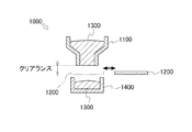
図8に示すように、従来のすり切り方式の粉体供給装置1000は、収容部1100と、シャッター1200と、を有していた。従来の粉体供給装置1000は、収容部1100内の粉体1300を粉体容器1400内に供給する際に、シャッター1200を、収容部1100と粉体容器1400との間の位置(供給停止位置)からずらすことで粉体1300の供給を開始し、そして、シャッター1200を前記供給停止位置まで移動することで粉体1300の供給を停止していた。
As shown in FIG. 8, a conventional
しかし、シャッター1200が前記供給停止位置に存在するとき、シャッター1200と収容部1100との間のクリアランスが発生していた。そして、前記クリアランスが粉体粉径よりも大きかった。これによりシャッター1200によるすり切り時に粉漏れが発生していた。
However, when the
また、従来の粉体供給装置1000は、粉体1300の供給量を体積にて管理していたため、粉体容器1400内に供給した粉体1300の重量バラツキが大きくなることがあった。これにより、例えば、粉体容器1400内に供給された粉体(金属磁性粒子)1300がプレス成形されて圧粉磁性体(磁性材料を圧粉成形した部品)が製造された場合、製造された圧粉磁性体の品質のバラツキが大きくなることがあった。
In addition, since the conventional
本発明は、粉漏れを抑制でき、かつ、粉体容器内に供給した粉体の重量バラツキを低減することが可能な粉体供給装置および粉体供給方法を提供する。 The present invention provides a powder supply apparatus and a powder supply method capable of suppressing powder leakage and reducing the variation in weight of the powder supplied into the powder container.
請求項1に記載の粉体供給装置は、
所定の目標重量の粉体を粉体容器内に供給するための粉体供給装置であって、
前記粉体を収容可能な収容空間が形成され、前記収容空間内の前記粉体を外部に流出させることが可能な孔部が形成され、前記孔部が前記粉体容器の上方に配置される収容部と、
前記収容部の孔部を開放・閉塞可能であり、前記孔部を開放することで前記収容空間内の粉体を前記孔部から自重落下させて前記粉体容器内に供給し、前記孔部を閉塞することで前記収容空間内の粉体が前記孔部から流出することを遮断するバルブ部と、
前記粉体容器内の前記粉体の重量を計測する重量計測部と、
前記バルブ部および重量計測部に接続される制御部と、を備え、
前記バルブ部は、上方移動されて前記孔部の周縁部に当接することにより、前記孔部との間の隙間をなくして前記孔部を閉塞し、下方移動されて前記孔部との間に隙間を発生させることにより、前記孔部を開放し、
前記制御部は、前記バルブ部により前記孔部を開放させ、そして前記孔部の開放量を一定の大きさに保持させ、さらに前記重量計測部から受信する前記粉体容器内の前記粉体の重量が所定のバルブ閉じ重量になったときに前記バルブ部により前記孔部を閉塞させることで前記粉体を前記粉体容器内に供給し、
前記バルブ閉じ重量は、前記目標重量が所定の浮遊粉体量に応じて補正された値であり、
前記浮遊粉体量は、前記制御部により前記粉体が前記粉体容器内に供給される場合において、前記孔部の開放後、前記孔部から自重落下する前記粉体の流量変動が安定しているときの前記粉体の流速に基づいて算出され、または、前記孔部から自重落下する前記粉体の流量が安定している間における前記孔部の開放量の時間積分と、そのときの前記重量計測部の計測値との差分に基づいて算出される。
また、請求項2に記載の粉体供給装置は、
所定の目標重量の粉体を粉体容器内に供給するための粉体供給装置であって、
前記粉体を収容可能な収容空間が形成され、前記収容空間内の前記粉体を外部に流出させることが可能な孔部が形成され、前記孔部が前記粉体容器の上方に配置される収容部と、
前記収容部の孔部を開放・閉塞可能であり、前記孔部を開放することで前記収容空間内の粉体を前記孔部から自重落下させて前記粉体容器内に供給し、前記孔部を閉塞することで前記収容空間内の粉体が前記孔部から流出することを遮断するバルブ部と、
前記粉体容器内の前記粉体の重量を計測する重量計測部と、
前記バルブ部および重量計測部に接続される制御部と、を備え、
前記バルブ部は、上方移動されて前記孔部の周縁部に当接することにより、前記孔部との間の隙間をなくして前記孔部を閉塞し、下方移動されて前記孔部との間に隙間を発生させることにより、前記孔部を開放し、
前記制御部は、前記バルブ部により前記孔部を開放させ、そして前記孔部の開放量を一定の大きさに保持させ、さらに前記重量計測部から受信する前記粉体容器内の前記粉体の重量が所定のバルブ閉じ重量になったときに前記バルブ部により前記孔部を閉塞させることで前記粉体を前記粉体容器内に供給し、
前記バルブ閉じ重量は、前記目標重量が所定の浮遊粉体量に応じて補正された値であり、
前記浮遊粉体量は、前記制御部により前記粉体が前記粉体容器内に供給される場合において、前記孔部の開放後、前記孔部から自重落下する前記粉体の流量変動が安定しているときの前記粉体の流速に基づいて算出される。
また、請求項3に記載の粉体供給装置は、
所定の目標重量の粉体を粉体容器内に供給するための粉体供給装置であって、
前記粉体を収容可能な収容空間が形成され、前記収容空間内の前記粉体を外部に流出させることが可能な孔部が形成され、前記孔部が前記粉体容器の上方に配置される収容部と、
前記収容部の孔部を開放・閉塞可能であり、前記孔部を開放することで前記収容空間内の粉体を前記孔部から自重落下させて前記粉体容器内に供給し、前記孔部を閉塞することで前記収容空間内の粉体が前記孔部から流出することを遮断するバルブ部と、
前記粉体容器内の前記粉体の重量を計測する重量計測部と、
前記バルブ部および重量計測部に接続される制御部と、を備え、
前記バルブ部は、上方移動されて前記孔部の周縁部に当接することにより、前記孔部との間の隙間をなくして前記孔部を閉塞し、下方移動されて前記孔部との間に隙間を発生させることにより、前記孔部を開放し、
前記制御部は、前記バルブ部により前記孔部を開放させ、そして前記孔部の開放量を一定の大きさに保持させ、さらに前記重量計測部から受信する前記粉体容器内の前記粉体の重量が所定のバルブ閉じ重量になったときに前記バルブ部により前記孔部を閉塞させることで前記粉体を前記粉体容器内に供給し、
前記バルブ閉じ重量は、前記目標重量が所定の浮遊粉体量に応じて補正された値であり、
前記浮遊粉体量は、前記制御部により前記粉体が前記粉体容器内に供給される場合において、前記孔部の開放後、前記孔部から自重落下する前記粉体の流量が安定している間における前記孔部の開放量の時間積分と、そのときの前記重量計測部の計測値との差分に基づいて算出される。
また、請求項4に記載の粉体供給装置は、
所定の目標重量の粉体を粉体容器内に供給するための粉体供給装置であって、
前記粉体を収容可能な収容空間が形成され、前記収容空間内の前記粉体を外部に流出させることが可能な孔部が形成され、前記孔部が前記粉体容器の上方に配置される収容部と、
前記収容部の孔部を開放・閉塞可能であり、前記孔部を開放することで前記収容空間内の粉体を前記孔部から自重落下させて前記粉体容器内に供給し、前記孔部を閉塞することで前記収容空間内の粉体が前記孔部から流出することを遮断するバルブ部と、
前記粉体容器内の前記粉体の重量を計測する重量計測部と、
前記バルブ部および重量計測部に接続される制御部と、を備え、
前記バルブ部は、上方移動されて前記孔部の周縁部に当接することにより、前記孔部との間の隙間をなくして前記孔部を閉塞し、下方移動されて前記孔部との間に隙間を発生させることにより、前記孔部を開放し、
前記制御部は、前記バルブ部により前記孔部を開放させ、そして前記孔部の開放量を一定の大きさに保持させ、さらに前記重量計測部から受信する前記粉体容器内の前記粉体の重量が所定のバルブ閉じ重量になったときに前記バルブ部により前記孔部を閉塞させることで前記粉体を前記粉体容器内に供給し、
前記バルブ閉じ重量は、前記目標重量が所定の浮遊粉体量に応じて補正された値であって、以下の[数1]に示す値となるとともに、前記浮遊粉体量は、前記制御部により前記粉体が前記粉体容器内に供給される場合において、前記孔部の開放後、前記孔部から自重落下する前記粉体の流量変動が安定しているときの前記粉体の流速に基づいて以下の[数1]に示す値となるように算出される、
または、
前記バルブ閉じ重量は、前記目標重量が所定の浮遊粉体量に応じて補正された値であって、以下の[数2]に示す値となるとともに、前記浮遊粉体量は、前記制御部により前記粉体が前記粉体容器内に供給される場合において、前記孔部の開放後、前記孔部から自重落下する前記粉体の流量が安定している間における前記孔部の開放量の時間積分と、そのときの前記重量計測部の計測値との差分に基づいて以下の[数2]に示す値となるように算出される粉体供給装置。
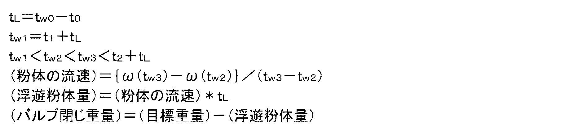
t0は、前記孔部の開放が開始される時間を示し、
tw0は、前記孔部の開放後、前記重量計測部の計測値が増加し始める時間を示し、
t1は、前記孔部の開放量が前記一定の大きさに保持されている期間の開始時間を示し、
t2は、前記孔部の開放量が前記一定の大きさに保持されている期間の終了時間を示し、
tw2およびtw3は、tw1<tw2<tw3<t2+tL、の範囲内の時間であり、
ω(tw2)は、時間tw2のときの前記重量計測部の計測値を示し、
ω(tw3)は、時間tw3のときの前記重量計測部の計測値を示す。
t 4 は、前記孔部の開放が開始される時間を示し、
t w4 は、前記孔部の開放後、前記重量計測部の計測値が増加し始める時間を示し、
t 5 は、前記孔部の開放量が前記一定の大きさに保持されている期間の開始時間を示し、
t 6 は、前記孔部の開放量が前記一定の大きさに保持されている期間の終了時間を示し、
x(t)は、前記孔部の開放量を示し、
Sは、x(t)の時間積分を示し、
ΔSは、単位時間あたりのSの変化量を示し、
Δωは、単位時間あたりの前記重量計測部の計測値の変化量を示し、
t wa は、t w5 <t wa <t 6 、の範囲内の時間であり、
β(t wa )は、時間t wa のときのβの値を示し、
S(t wa )は、時間t 4 からt wa の範囲でx(t)を時間積分したときの値を示し、
ω f は、前記粉体の供給が開始されるときの前記重量計測部の計測値を示し、
ω(t wa )は、時間t wa のときの前記重量計測部の計測値を示す。
The powder supply apparatus according to
A powder supply device for supplying powder of a predetermined target weight into a powder container,
An accommodation space capable of accommodating the powder is formed, a hole portion through which the powder in the accommodation space can flow out is formed, and the hole portion is disposed above the powder container. A containment section;
The hole of the container can be opened / closed, and by opening the hole, the powder in the container space is dropped by its own weight from the hole and supplied into the powder container. A valve part that blocks the powder in the accommodation space from flowing out of the hole by closing
A weight measuring unit for measuring the weight of the powder in the powder container;
A control unit connected to the valve unit and the weight measurement unit,
The valve portion is moved upward and comes into contact with the peripheral portion of the hole portion, thereby eliminating the gap between the valve portion and closing the hole portion, and being moved downward and between the hole portion. By generating a gap, the hole is opened,
The control unit opens the hole by the valve unit, holds the opening amount of the hole at a constant size, and further receives the powder in the powder container received from the weight measuring unit. Supplying the powder into the powder container by closing the hole by the valve when the weight reaches a predetermined valve closing weight,
The valve closing weight is a value obtained by correcting the target weight according to a predetermined amount of suspended powder,
When the powder is supplied into the powder container by the control unit, the amount of the suspended powder is stable when the flow rate of the powder falling by its own weight from the hole after the hole is opened is stabilized. Calculated based on the flow velocity of the powder at the time, or the time integration of the opening amount of the hole while the flow rate of the powder falling by its own weight from the hole is stable, and at that time It is calculated based on the difference from the measured value of the weight measuring unit.
Moreover, the powder supply apparatus according to
A powder supply device for supplying powder of a predetermined target weight into a powder container,
An accommodation space capable of accommodating the powder is formed, a hole portion through which the powder in the accommodation space can flow out is formed, and the hole portion is disposed above the powder container. A containment section;
The hole of the container can be opened / closed, and by opening the hole, the powder in the container space is dropped by its own weight from the hole and supplied into the powder container. A valve part that blocks the powder in the accommodation space from flowing out of the hole by closing
A weight measuring unit for measuring the weight of the powder in the powder container;
A control unit connected to the valve unit and the weight measurement unit,
The valve portion is moved upward and comes into contact with the peripheral portion of the hole portion, thereby eliminating the gap between the valve portion and closing the hole portion, and being moved downward and between the hole portion. By generating a gap, the hole is opened,
The control unit opens the hole by the valve unit, holds the opening amount of the hole at a constant size, and further receives the powder in the powder container received from the weight measuring unit. Supplying the powder into the powder container by closing the hole by the valve when the weight reaches a predetermined valve closing weight,
The valve closing weight is a value obtained by correcting the target weight according to a predetermined amount of suspended powder,
When the powder is supplied into the powder container by the control unit, the amount of the suspended powder is stable when the flow rate of the powder falling by its own weight from the hole after the hole is opened is stabilized. It is calculated based on the flow rate of the powder when being.
Moreover, the powder supply apparatus according to claim 3 is:
A powder supply device for supplying powder of a predetermined target weight into a powder container,
An accommodation space capable of accommodating the powder is formed, a hole portion through which the powder in the accommodation space can flow out is formed, and the hole portion is disposed above the powder container. A containment section;
The hole of the container can be opened / closed, and by opening the hole, the powder in the container space is dropped by its own weight from the hole and supplied into the powder container. A valve part that blocks the powder in the accommodation space from flowing out of the hole by closing
A weight measuring unit for measuring the weight of the powder in the powder container;
A control unit connected to the valve unit and the weight measurement unit,
The valve portion is moved upward and comes into contact with the peripheral portion of the hole portion, thereby eliminating the gap between the valve portion and closing the hole portion, and being moved downward and between the hole portion. By generating a gap, the hole is opened,
The control unit opens the hole by the valve unit, holds the opening amount of the hole at a constant size, and further receives the powder in the powder container received from the weight measuring unit. Supplying the powder into the powder container by closing the hole by the valve when the weight reaches a predetermined valve closing weight,
The valve closing weight is a value obtained by correcting the target weight according to a predetermined amount of suspended powder,
The floating powder quantity, in the case where the powder by the control unit is supplied to the powder in the container, after opening of the hole, the flow rate of the powder to be free-fall before Kiana unit stable It is calculated based on the difference between the time integration of the opening amount of the hole during the period and the measured value of the weight measuring unit at that time.
Moreover, the powder supply apparatus according to claim 4 comprises:
A powder supply device for supplying powder of a predetermined target weight into a powder container,
An accommodation space capable of accommodating the powder is formed, a hole portion through which the powder in the accommodation space can flow out is formed, and the hole portion is disposed above the powder container. A containment section;
The hole of the container can be opened / closed, and by opening the hole, the powder in the container space is dropped by its own weight from the hole and supplied into the powder container. A valve part that blocks the powder in the accommodation space from flowing out of the hole by closing
A weight measuring unit for measuring the weight of the powder in the powder container;
A control unit connected to the valve unit and the weight measurement unit,
The valve portion is moved upward and comes into contact with the peripheral portion of the hole portion, thereby eliminating the gap between the valve portion and closing the hole portion, and being moved downward and between the hole portion. By generating a gap, the hole is opened,
The control unit opens the hole by the valve unit, holds the opening amount of the hole at a constant size, and further receives the powder in the powder container received from the weight measuring unit. Supplying the powder into the powder container by closing the hole by the valve when the weight reaches a predetermined valve closing weight,
The valve closes by weight, the target weight is I corrected value der in accordance with a predetermined floating amount of powder, with the values shown in the following [Equation 1], the floating powder quantity, the control When the powder is supplied into the powder container by the part, the flow rate of the powder when the flow rate fluctuation of the powder falling by its own weight from the hole is stable after the opening of the hole Ru is calculated as a value in the following
Or
The valve closing weight is a value obtained by correcting the target weight according to a predetermined amount of suspended powder, and is a value represented by the following [Equation 2]. In the case where the powder is supplied into the powder container by the above, after the opening of the hole, the opening amount of the hole while the flow rate of the powder falling by its own weight from the hole is stable. The powder supply apparatus calculated so that it may become the value shown in the following [Equation 2] based on the difference of time integration and the measured value of the said weight measurement part at that time.
t 0 indicates the time when the opening of the hole starts,
t w0 indicates the time when the measured value of the weight measuring unit starts to increase after the opening of the hole,
t 1 indicates a start time of a period in which the opening amount of the hole is held at the constant size;
t 2 represents the end time of the period during which the opening amount of the hole is held in the predetermined size,
t w2 and t w3 are times within the range of t w1 <t w2 <t w3 <t 2 + t L ,
ω (t w2 ) represents the measurement value of the weight measurement unit at time t w2 ,
ω (t w3 ) indicates a measurement value of the weight measurement unit at time t w3 .
t 4 indicates the time when the opening of the hole starts,
t w4 indicates the time when the measurement value of the weight measurement unit starts to increase after the opening of the hole,
t 5 represents the start time of a period in which the opening amount of the hole is held at the constant size;
t 6 indicates the end time of the period during which the opening amount of the hole is held in the predetermined size,
x (t) represents the opening amount of the hole,
S represents the time integral of x (t),
ΔS represents the amount of change in S per unit time,
Δω indicates the amount of change in the measurement value of the weight measurement unit per unit time,
t wa is a time in the range of t w5 <t wa <t 6 ,
β (t wa ) indicates the value of β at time t wa ,
S (t wa ) represents a value when x (t) is integrated over time in the range of time t 4 to t wa ;
ω f indicates the measurement value of the weight measurement unit when the supply of the powder is started,
ω (t wa ) indicates the measurement value of the weight measurement unit at time t wa .
請求項5に記載の粉体供給装置においては、
前記浮遊粉体量およびバルブ閉じ重量が、以下の[数1]に示す値となる。
t0は、前記孔部の開放が開始される時間を示し、
tw0は、前記孔部の開放後、前記重量計測部の計測値が増加し始める時間を示し、
t1は、前記孔部の開放量が前記一定の大きさに保持されている期間の開始時間を示し、
t2は、前記孔部の開放量が前記一定の大きさに保持されている期間の終了時間を示し、
tw2およびtw3は、tw1<tw2<tw3<t2+tL、の範囲内の時間であり、
ω(tw2)は、時間tw2のときの前記重量計測部の計測値を示し、
ω(tw3)は、時間tw3のときの前記重量計測部の計測値を示す。
In the powder supply apparatus according to claim 5 ,
Before Symbol floating powder quantity and the valve closes weight becomes the value shown in
t 0 indicates the time when the opening of the hole starts,
t w0 indicates the time when the measured value of the weight measuring unit starts to increase after the opening of the hole,
t 1 indicates a start time of a period in which the opening amount of the hole is held at the constant size;
t 2 represents the end time of the period during which the opening amount of the hole is held in the predetermined size,
t w2 and t w3 are times within the range of t w1 <t w2 <t w3 <t 2 + t L ,
ω (t w2 ) represents the measurement value of the weight measurement unit at time t w2 ,
ω (t w3 ) indicates a measurement value of the weight measurement unit at time t w3 .
請求項6に記載の粉体供給装置においては、
前記浮遊粉体量およびバルブ閉じ重量が、以下の[数2]に示す値となる。
t4は、前記孔部の開放が開始される時間を示し、
tw4は、前記孔部の開放後、前記重量計測部の計測値が増加し始める時間を示し、
t5は、前記孔部の開放量が前記一定の大きさに保持されている期間の開始時間を示し、
t6は、前記孔部の開放量が前記一定の大きさに保持されている期間の終了時間を示し、
x(t)は、前記孔部の開放量を示し、
Sは、x(t)の時間積分を示し、
ΔSは、単位時間あたりのSの変化量を示し、
Δωは、単位時間あたりの前記重量計測部の計測値の変化量を示し、
twaは、tw5<twa<t6、の範囲内の時間であり、
β(twa)は、時間twaのときのβの値を示し、
S(twa)は、時間t4からtwaの範囲でx(t)を時間積分したときの値を示し、
ωfは、前記粉体の供給が開始されるときの前記重量計測部の計測値を示し、
ω(twa)は、時間twaのときの前記重量計測部の計測値を示す。
In the powder supply apparatus according to claim 6 ,
Before Symbol floating powder quantity and the valve closing weight, the values shown in
t 4 indicates the time when the opening of the hole starts,
t w4 indicates the time when the measurement value of the weight measurement unit starts to increase after the opening of the hole,
t 5 represents the start time of a period in which the opening amount of the hole is held at the constant size;
t 6 indicates the end time of the period during which the opening amount of the hole is held in the predetermined size,
x (t) represents the opening amount of the hole,
S represents the time integral of x (t),
ΔS represents the amount of change in S per unit time,
Δω indicates the amount of change in the measurement value of the weight measurement unit per unit time,
t wa is a time in the range of t w5 <t wa <t 6 ,
β (t wa ) indicates the value of β at time t wa ,
S (t wa ) represents a value when x (t) is integrated over time in the range of time t 4 to t wa ;
ω f indicates the measurement value of the weight measurement unit when the supply of the powder is started,
ω (t wa ) indicates the measurement value of the weight measurement unit at time t wa .
請求項7に記載の粉体供給装置においては、
前記制御部は、前記バルブ部により前記孔部を開放させ、そして前記孔部の開放量を一定の大きさに保持させ、さらに前記孔部を閉塞させるまでを1サイクルとして、そのサイクルを複数回数繰り返すことで、前記粉体を前記粉体容器内に供給し、
前記目標重量およびバルブ閉じ重量は、前記複数のサイクル毎に設定される。
In the powder supply apparatus according to claim 7 ,
The control part opens the hole part by the valve part, maintains the opening amount of the hole part at a constant size, and further closes the hole part as one cycle. By repeating, the powder is supplied into the powder container,
The target weight and the valve closing weight are set for each of the plurality of cycles.
請求項8に記載の粉体供給装置においては、
前記制御部は、前記複数のサイクルの完了時における前記重量計測部の計測値と前記目標重量との誤差を記憶し、記憶した誤差に基づいて前記バルブ閉じ重量を補正する。
In the powder supply apparatus according to claim 8 ,
The control unit stores an error between the measurement value of the weight measurement unit and the target weight at the completion of the plurality of cycles, and corrects the valve closing weight based on the stored error.
請求項9に記載の粉体供給装置においては、
前記バルブ部により前記孔部の開放量を一定の大きさに保持させるときの前記孔部の開放量を前記複数のサイクル毎に段階的に調整可能である。
In the powder supply apparatus according to claim 9 ,
The opening amount of the hole portion when the opening amount of the hole portion is held at a constant size by the valve portion can be adjusted step by step for each of the plurality of cycles.
請求項10に記載の粉体供給方法は、
所定の目標重量の粉体を粉体容器内に供給するための粉体供給方法であって、
前記粉体を収容可能な収容空間が形成され、前記収容空間内の前記粉体を外部に流出させることが可能な孔部が形成され、前記孔部が前記粉体容器の上方に配置される収容部と、
前記収容部の孔部を開放・閉塞可能であり、前記孔部を開放することで前記収容空間内の粉体を前記孔部から自重落下させて前記粉体容器内に供給し、前記孔部を閉塞することで前記収容空間内の粉体が前記孔部から流出することを遮断するバルブ部と、
前記粉体容器内の前記粉体の重量を計測する重量計測部と、
前記バルブ部および重量計測部に接続される制御部と、を備え、
前記バルブ部が、上方移動されて前記孔部の周縁部に当接することにより、前記孔部との間の隙間をなくして前記孔部を閉塞し、下方移動されて前記孔部との間に隙間を発生させることにより、前記孔部を開放する粉体供給装置を用いて行われ、
前記制御部により、前記バルブ部に前記孔部を開放させ、そして前記孔部の開放量を一定の大きさに保持させ、さらに前記重量計測部から受信する前記粉体容器内の前記粉体の重量が所定のバルブ閉じ重量になったときに前記バルブ部に前記孔部を閉塞させることで前記粉体を前記粉体容器内に供給し、
前記バルブ閉じ重量は、前記目標重量が所定の浮遊粉体量に応じて補正された値であり、
前記浮遊粉体量は、前記制御部により前記粉体が前記粉体容器内に供給される場合において、前記孔部の開放後、前記孔部から自重落下する前記粉体の流量変動が安定しているときの前記粉体の流速に基づいて算出され、または、前記孔部から自重落下する前記粉体の流量が安定している間における前記孔部の開放量の時間積分と、そのときの前記重量計測部の計測値との差分に基づいて算出される。
The powder supply method according to claim 10 ,
A powder supply method for supplying powder of a predetermined target weight into a powder container,
An accommodation space capable of accommodating the powder is formed, a hole portion through which the powder in the accommodation space can flow out is formed, and the hole portion is disposed above the powder container. A containment section;
The hole of the container can be opened / closed, and by opening the hole, the powder in the container space is dropped by its own weight from the hole and supplied into the powder container. A valve part that blocks the powder in the accommodation space from flowing out of the hole by closing
A weight measuring unit for measuring the weight of the powder in the powder container;
A control unit connected to the valve unit and the weight measurement unit ,
The valve portion is moved upward and comes into contact with the peripheral edge portion of the hole portion, thereby eliminating the gap between the hole portion and closing the hole portion, and moving downward and between the hole portion. By using a powder supply device that opens the hole by generating a gap ,
The control unit causes the valve unit to open the hole, holds the opening of the hole at a constant size, and further receives the powder in the powder container received from the weight measuring unit. Supplying the powder into the powder container by closing the hole in the valve when the weight reaches a predetermined valve closing weight;
The valve closing weight is a value obtained by correcting the target weight according to a predetermined amount of suspended powder,
When the powder is supplied into the powder container by the control unit, the amount of the suspended powder is stable when the flow rate of the powder falling by its own weight from the hole after the hole is opened is stabilized. Calculated based on the flow velocity of the powder at the time, or the time integration of the opening amount of the hole while the flow rate of the powder falling by its own weight from the hole is stable, and at that time It is calculated based on the difference from the measured value of the weight measuring unit.
本発明によれば、粉漏れを抑制でき、かつ、供給した粉体の重量バラツキを低減することが可能である。 According to the present invention, powder leakage can be suppressed and weight variation of the supplied powder can be reduced.
以下に、本発明に係る粉体供給装置の実施の一形態である粉体供給装置100について、図面を参照して説明する。
Below, the
粉体供給装置100は、所定の目標重量ωdの粉体1を粉体容器2内に供給するための装置である。
粉体1は、例えば、圧粉磁性体(磁性材料を圧粉成形した部品)の製造に用いられる金属磁性粒子である。前記圧粉磁性体は、粉体(金属磁性粒子)1が粉体容器2内に供給され、そして粉体容器2内に供給された粉体1が型内に供給され、そしてプレス成形されることによって製造される。
前記目標重量ωdは、粉体1を用いて製造される製品の種類等に応じて適宜決定される。
The
The target weight ω d is appropriately determined according to the type of product manufactured using the
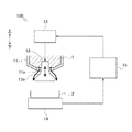
図1に示すように、粉体供給装置100は、収容部11と、バルブ部(ロッド部12およびアクチュエータ13)と、重量計測部14と、制御部15と、を備えている。
As shown in FIG. 1, the
収容部11は、有底の容器形状を有しており、粉体1を収容可能な収容空間が形成されている。収容部11の底部(下部)には、前記収容空間と収容部11外部との間を連通し、前記収容空間内の粉体1を収容部11外部に流出させることが可能な孔部11aが形成されている。
収容部11の孔部11aは、粉体容器2の上方に配置されている。
The
The
前記バルブ部は、粉体1を切り出すための装置であり、収容部11の孔部11aを開放・閉塞可能な装置である。
前記バルブ部は、ロッド部12およびアクチュエータ13を有している。
The valve portion is a device for cutting out the
The valve portion has a
ロッド部12は、上下に延在する棒形状を有している。ロッド部12の下端部には、下方に向かうにしたがって拡径するテーパ部12aが形成されている。
ロッド部12は、収容部11の前記収容空間内を上下方向に挿通しており、その下端部が孔部11aを通じて収容部11の外方に突出している。ロッド部12の下端部のテーパ部12aにおいては、その下側の寸法が孔部11aの寸法よりも大きく構成されており、その上側の寸法が孔部11aの寸法よりも小さく構成されている。
The
The
アクチュエータ(シリンダ、モータ等)13は、ロッド部12に接続されており、ロッド部12を上下動可能に構成されている。
The actuator (cylinder, motor, etc.) 13 is connected to the
ロッド部12がアクチュエータ13により上方移動されて、テーパ部12aが孔部11aの周縁部に当接すると、孔部11aとテーパ部12aとの間の隙間がなくなり、孔部11aが閉塞される。これにより、前記収容空間内の粉体1が孔部11aを通じて自重落下することが遮断される。
また、孔部11aがテーパ部12aによって閉塞された状態から、ロッド部12がアクチュエータ13により下方移動されると、孔部11aとテーパ部12aとの間に隙間が発生し、孔部11a(詳細には、孔部11aの一部)が開放される。これにより、前記収容空間内の粉体1が孔部11a(詳細には、孔部11aの内周面とテーパ部12aの外周面との間の隙間)を通じて自重落下し、粉体容器2内に供給される。
また、上記したようにテーパ部12aは下方に向かうにしたがって拡径している。これにより、アクチュエータ13がロッド部12の位置を上方に移動することで孔部11aとテーパ部12aとの間の隙間の寸法(孔部11aの開放量)が小さくなり、ロッド部12の位置を下方に移動することで孔部11aの開放量が大きくなる。
孔部11aからは、孔部11aの開放量に対応した重量の粉体1が流出(自重落下)する。
When the
Further, when the
Further, as described above, the tapered
From the
重量計測部(電子天びん等)14は、その上部に粉体容器2が載置されており、粉体容器2内に供給された粉体1の重量を計測する。
The weight measurement unit (electronic balance or the like) 14 has the
制御部15は、演算部(CPU)、記憶部(HDD、半導体メモリ等)等を有しており、コンピュータで構成可能である。
The
制御部15は、アクチュエータ13に接続されている。
制御部15は、アクチュエータ13に閉信号を送信することで、アクチュエータ13によりロッド部12を上方移動させる。また、制御部15は、アクチュエータ13に開信号を送信することで、アクチュエータ13によりロッド部12を下方移動させる。
制御部15は、アクチュエータ13に前記閉信号/開信号を送信して、ロッド部の上下方向の位置を変更することで、孔部11aの開放量を変更可能であり、これにより単位時間あたりの孔部11aからの粉体1の流出量が変更される。
また、制御部15は、アクチュエータ13によりロッド部12を上下動させるときに、ロッド部12の移動速度を変更し、孔部11aの開閉速度を変更することが可能である。
The
The
The
Moreover, when the
制御部15は、重量計測部14に接続されており、重量計測部14から粉体容器2内の粉体1の重量に係る情報を受信可能である。
The
制御部15は、閉塞されている状態の孔部11aを前記バルブ部(ロッド部12およびアクチュエータ13)により開放させ、そして孔部11aの開放量を一定の大きさに保持させ、さらに開放状態の孔部11aを前記バルブにより閉塞させるまでを1サイクルとして、そのサイクルを二回繰り返すことで、粉体1を粉体容器2内に供給することとする。また、制御部15は、第1サイクルの完了後、所定時間経過後に第2サイクルを開始することとする。
The
第1サイクルでは多量の粉体1が供給される。また第1サイクルでは目標重量が目標重量ωd1に設定されている。また、第1サイクルでは、第2サイクルに比べて、孔部11aの開放量(バルブ開き量)が大きく、かつ、孔部11aの開閉速度が高速に構成されている(高速粉供給)。これは、短時間で多量の粉体1を粉体容器2内に供給するためである。
In the first cycle, a large amount of
第1サイクルにおいては、制御部15は、前記バルブ部(ロッド部12およびアクチュエータ13)により孔部11aを開放させ、そして孔部11aの開放量を一定の大きさx1に保持させ、さらに重量計測部14から受信する粉体容器2内の粉体1の重量が所定のバルブ閉じ重量ω1になったときに前記バルブ部により孔部11aを閉塞させることで粉体1を粉体容器2内に供給する。
In the first cycle, the
以下では、バルブ閉じ重量ω1について図2の第一ライン16と第三ライン18を参照して説明する。
Hereinafter, the valve closing weight ω 1 will be described with reference to the
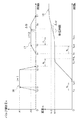
図2および図3には、第一ライン16と、第二ライン17と、第三ライン18と、が表されている。
第一ライン16は、第1サイクルにおいて制御部15により孔部11aが開放・閉塞されるときの、時間tと孔部11aの開放量x(バルブ開き量x)との関係を示すラインである。
第二ライン17は、第2サイクルにおいて制御部15により孔部11aが開放・閉塞されるときの、時間tと孔部11aの開放量x(バルブ開き量x)との関係を示すラインである。第2サイクルについての説明は後述する。
第三ライン18は、第一ライン16および第二ライン17に示すように孔部11aが開放・閉塞されるときの、時間tと重量計測部14の計測値ωとの関係を示すラインである。
2 and 3, the
The
The
The
バルブ閉じ重量ω1は、目標重量ωd1が所定の浮遊粉体量ωa1に応じて補正された値である。
浮遊粉体量ωa1は、図2の第一ライン16および第三ライン18に示すように制御部15により粉体1が粉体容器2内に供給される場合において、孔部11aから自重落下する粉体1の流量変動が安定しているときに、孔部11aと粉体容器2との間に存在(浮遊)している粉体1の推定重量であり、孔部11aの開放後、孔部11aから自重落下する粉体1の流量変動が安定しているときの粉体1の流速αに基づいて算出される。
浮遊粉体量ωa1、およびバルブ閉じ重量ω1は、具体的には以下の[数1]に示す値となる。
The valve closing weight ω 1 is a value obtained by correcting the target weight ω d1 according to a predetermined suspended powder amount ω a1 .
As shown in the
The suspended powder amount ω a1 and the valve closing weight ω 1 are specifically the values shown in the following [Equation 1].
ただし、前記[数1]に関して、
t0は、孔部11aの開放が開始される時間を示し、
tw0は、孔部11aの開放後、重量計測部14の計測値が増加し始める時間を示し、
t1は、孔部11aの開放量が前記一定の大きさx1に保持されている期間の開始時間を示し、
t2は、孔部11aの開放量が前記一定の大きさx1に保持されている期間の終了時間を示し、
tw2およびtw3は、tw1<tw2<tw3<t2+tL、の範囲内の時間であり、すなわち孔部11aから自重落下する粉体1の流量変動が安定している時間であり、
ω(tw2)は、時間tw2のときの重量計測部14の計測値を示し、
ω(tw3)は、時間tw3のときの重量計測部14の計測値を示す。
However, regarding the above [Equation 1],
t 0 indicates the time when opening of the
t w0 indicates the time when the measured value of the
t 1 indicates the start time of a period in which the opening amount of the
t 2 represents the end time of the period during which the opening amount of the
t w2 and t w3 are times within the range of t w1 <t w2 <t w3 <t 2 + t L , that is, a time during which the flow rate fluctuation of the
ω (t w2 ) indicates the measurement value of the
ω (t w3 ) indicates a measurement value of the
以上のように、孔部11aから自重落下する粉体1の流量をリアルタイムに計測し、孔部11aの開放後、粉体1の流量変動が安定しているときの粉体1の流速αから重量計測部14の検出遅れ分(浮遊粉体量ωa1)を推定し、その分だけ孔部11aを閉塞するタイミングを早く構成する((バルブ閉じ重量ω1)=(目標重量ωd1)−(浮遊粉体量ωa1))。これにより、粉体供給装置100は、粉体容器2内に供給した粉体1に関し、目標重量ωd1に対する重量バラツキを低減することが可能となり、精度よく粉体1を供給することが可能となる。
また、粉体供給装置100は、粉体容器2内に供給した粉体1の重量で孔部11aを閉塞するタイミングを決定する。これにより、粉体容器2内に供給した粉体1の重量バラツキを低減することが可能である。
また、粉体供給装置100は、従来の粉体供給装置1000のようなすり切り方式ではなく、収容部11の孔部11aの開放・閉塞を制御することで粉体1の供給量を管理する方式とするため、粉漏れを抑制することが可能である。
As described above, the flow rate of the
In addition, the
In addition, the
第2サイクルでは第1サイクルよりも少量の粉体1が供給される。また第2サイクルでは目標重量が目標重量ωd2(=ωd)に設定されている。また、第2サイクルでは孔部11aの開放量が第1サイクルに比べて小さく、かつ、孔部11aの開閉速度が低速に構成されている(高精度粉供給)。これは、ロッド部12の高速動作の衝撃による粉体1の落下を抑制し、精度よく粉体1を粉体容器2内に供給するためである。
In the second cycle, a smaller amount of
第2サイクルにおいては、制御部15は、第1サイクルの粉体1供給を完了してから所定時間経過後に、前記バルブ部(ロッド部12およびアクチュエータ13)により孔部11aを開放させ、そして孔部11aの開放量を一定の大きさx2(x2<x1)に保持させ、さらに重量計測部14から受信する粉体容器2内の粉体1の重量が所定のバルブ閉じ重量ω2になったときに前記バルブ部により孔部11aを閉塞させることで粉体1を粉体容器2内に供給する。
In the second cycle, the
以下では、バルブ閉じ重量ω2について図3の第二ライン(x=x(t))17と第三ライン18を参照して説明する。
Hereinafter, the valve closing weight ω 2 will be described with reference to the second line (x = x (t)) 17 and the
バルブ閉じ重量ω2は、目標重量ωd2が所定の浮遊粉体量ωa2に応じて補正された値である。
浮遊粉体量ωa2は、図3の第二ライン17および第三ライン18に示すように制御部15により粉体1が粉体容器2内に供給される場合において、孔部11aから自重落下する粉体1の流量が安定しているときに、孔部11aと粉体容器2との間に存在(浮遊)している粉体1の推定重量であり、孔部11aの開放後、孔部11aから自重落下する粉体1の流量が安定している間における孔部11aの開放量xの時間積分と、そのときの重量計測部14の計測値との差分に基づいて算出される。
浮遊粉体量ωa2、およびバルブ閉じ重量ω2は、具体的には以下の[数2]に示す値となる。
The valve closing weight ω 2 is a value obtained by correcting the target weight ω d2 according to a predetermined suspended powder amount ω a2 .
The amount of suspended powder ω a2 falls by its own weight from the
The amount of suspended powder ω a2 and the valve closing weight ω 2 are specifically the values shown in the following [Equation 2].
ただし、前記[数3]において、
t4は、孔部11aの開放が開始される時間を示し、
tw4は、孔部11aの開放後、重量計測部14の計測値が増加し始める時間を示し、
t5は、孔部11aの開放量が前記一定の大きさx2に保持されている期間の開始時間を示し、
t6は、孔部11aの開放量が前記一定の大きさx2に保持されている期間の終了時間を示し、
x(t)は、孔部11aの開放量(バルブ開き量)を示し、
Sは、x(t)の時間積分を示し、
ΔSは、単位時間あたりのSの変化量を示し、
Δωは、単位時間あたりの重量計測部14の計測値ωの変化量を示し、
twaは、tw5<twa<t6、の範囲内の時間であり、すなわち孔部11aから自重落下する粉体1の流量が安定している時間であり、
β(twa)は、時間twaのときのβの値を示し、
S(twa)は、時間t4からtwaの範囲でx(t)を時間積分したときの値を示し、
ωf1は、図3に示す時間(t3+tL)から(tw4)の間における重量計測部14の計測値であり、粉体1の供給が開始されるとき(第2サイクルが開始されるとき)の重量計測部14の計測値を示し、すなわち第1サイクルが完了したときの重量計測部14の計測値を示し、
ω(twa)は、時間twaのときの重量計測部14の計測値を示す。
However, in the above [Equation 3],
t 4 indicates the time opening of the
tw4 indicates the time when the measured value of the
t 5 indicates the start time of the period during which the opening amount of the
t 6 indicates the end time of the period during which the opening amount of the
x (t) represents the opening amount (valve opening amount) of the
S represents the time integral of x (t),
ΔS represents the amount of change in S per unit time,
Δω represents the amount of change in the measurement value ω of the
t wa is a time within a range of t w5 <t wa <t 6 , that is, a time during which the flow rate of the
β (t wa ) indicates the value of β at time t wa ,
S (t wa ) represents a value when x (t) is integrated over time in the range of time t 4 to t wa ;
ω f1 is a measured value of the
ω (t wa ) indicates a measurement value of the
以上のように、孔部11aから自重落下する粉体1の流量をリアルタイムに計測し、孔部11aの開放後、粉体1の流量が安定している間における孔部11aの開放量の時間積分と、そのときの重量計測部14の計測値との関係から重量計測部14の検出遅れ分(浮遊粉体量ωa2)を推定し、その分だけ孔部11aを閉塞するタイミングを早く構成する((バルブ閉じ重量ω2)=(目標重量ωd2)−(浮遊粉体量ωa2))。これにより、粉体供給装置100は、粉体容器2内に供給した粉体1に関し、目標重量ωd2に対する重量バラツキを低減することが可能となり、精度よく粉体1を供給することが可能となる。
また、粉体供給装置100は、粉体容器2内に供給した粉体1の重量で孔部11aを閉塞するタイミングを決定する。これにより、粉体容器2内に供給した粉体1の重量バラツキを低減することが可能である。
また、粉体供給装置100は、従来の粉体供給装置1000のようなすり切り方式ではなく、収容部11の孔部11aの開放・閉塞を制御することで粉体1の供給量を管理する方式とするため、粉漏れを抑制することが可能である。
As described above, the flow rate of the
In addition, the
In addition, the
なお、本実施形態では制御部15が前記バルブ部により孔部11aを開放させ、そして孔部11aの開放量を一定の大きさに保持させ、さらに孔部11aを閉塞させるまでのサイクルを二回繰り返すように構成したが、そのサイクルを一回で完了するように構成してもよく、または複数回数(二回以上)繰り返すように構成してもよい。この場合、前記目標重量およびバルブ閉じ重量は、サイクル毎に設定される。また、前記バルブ閉じ重量は、前記[数1]または[数2]に基づいて算出される。
In this embodiment, the
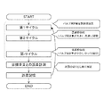
また、図4に示すように、制御部15が前記サイクルを複数回数(i回)繰り返す場合において、制御部15は、複数のサイクルの完了時(第iサイクルの完了時)における重量計測部14の計測値ωfioldと目標重量ωdiとの誤差(差分および/または比率)を記憶し、記憶した誤差に基づいて(差分・比率を利用して)バルブ閉じ重量ωioldを補正するように構成してもよい。補正後のバルブ閉じ重量ωiは、具体的には以下の
[数3]に示す値となる。
As shown in FIG. 4, when the
ただし、前記[数3]に関して、補正係数kは任意の定数とする。 However, with respect to [Formula 3], the correction coefficient k is an arbitrary constant.
以上のように、制御部15は重量計測部14の計測値ωfioldと目標重量ωdiとの誤差に基づいてバルブ閉じ重量をωioldからωiに補正することで、次回の粉体1供給時(切り出し時)からは孔部11aを閉塞するタイミングを重量計測部14の計測値がバルブ閉じ重量ωiになったときに変更することになる。これにより、粉体容器2内に供給した粉体1に関し、目標重量ωdiに対する重量バラツキを低減することが可能となり、精度よく粉体1を供給することが可能となる。
また、制御部15は上記したバルブ閉じ重量の補正を毎回行うことで、複数のサイクルの完了時(第iサイクルの完了時)における重量計測部14の計測値と目標重量ωdiとの差を縮めていくことが可能となり、より精度よく粉体1を供給することが可能となる。
As described above, the
In addition, the
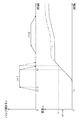
なお、図5の実線は、制御部15が前記サイクルを2回繰り返す場合で(i=2)、第1サイクルのバルブ閉じ重量をω1oldとする構成で、第1サイクル・第2サイクルを行ったときの時間tとバルブ開き量xと重量計測部14の計測値ωとの関係を示すラインを表している。
また、図5の一点鎖線は、制御部15が第2サイクルの完了時における重量計測部14の計測値と目標重量との誤差に基づいて第1サイクルのバルブ閉じ重量をω1oldからω1に補正し(前記[数3]参照)、第1サイクルのバルブ閉じ重量をω1とする構成で、第1サイクル・第2サイクルを行ったときの時間tとバルブ開き量xと重量計測部14の計測値ωとの関係を示すラインを表している。
The solid line in FIG. 5 shows the case where the
5 indicates that the valve closing weight of the first cycle is changed from ω 1old to ω 1 based on the error between the measured value of the
また、図6および図7に示すように、制御部15は、前記サイクルを複数回数繰り返す場合、前記バルブ部により孔部11aの開放量xを一定の大きさに保持させるときの孔部の開放量xを前記複数のサイクル毎に段階的に調整し、サイクル回数の増加に伴って孔部の開放量xを小さくするように構成してもよい。このように粉体1の重量バラツキは大きいが高速に粉体1を供給可能な方法(孔部11aの開放量x・大)と、粉体1の供給スピードは低速だが粉体1の重量バラツキは小さく、精度よく粉体1を供給可能な方法(孔部11aの開放量x・小)とを組み合わせることにより、短時間で精度よく粉体1を供給することが可能となる。
Also, as shown in FIGS. 6 and 7, the
1 粉体
2 粉体容器
11 収容部
11a 孔部
12 ロッド部
12a テーパ部
13 アクチュエータ
14 重量計測部
15 制御部
16 第一ライン
17 第二ライン
18 第三ライン
100 粉体供給装置
DESCRIPTION OF
Claims (10)
前記粉体を収容可能な収容空間が形成され、前記収容空間内の前記粉体を外部に流出させることが可能な孔部が形成され、前記孔部が前記粉体容器の上方に配置される収容部と、
前記収容部の孔部を開放・閉塞可能であり、前記孔部を開放することで前記収容空間内の粉体を前記孔部から自重落下させて前記粉体容器内に供給し、前記孔部を閉塞することで前記収容空間内の粉体が前記孔部から流出することを遮断するバルブ部と、
前記粉体容器内の前記粉体の重量を計測する重量計測部と、
前記バルブ部および重量計測部に接続される制御部と、を備え、
前記バルブ部は、上方移動されて前記孔部の周縁部に当接することにより、前記孔部との間の隙間をなくして前記孔部を閉塞し、下方移動されて前記孔部との間に隙間を発生させることにより、前記孔部を開放し、
前記制御部は、前記バルブ部により前記孔部を開放させ、そして前記孔部の開放量を一定の大きさに保持させ、さらに前記重量計測部から受信する前記粉体容器内の前記粉体の重量が所定のバルブ閉じ重量になったときに前記バルブ部により前記孔部を閉塞させることで前記粉体を前記粉体容器内に供給し、
前記バルブ閉じ重量は、前記目標重量が所定の浮遊粉体量に応じて補正された値であり、
前記浮遊粉体量は、前記制御部により前記粉体が前記粉体容器内に供給される場合において、前記孔部の開放後、前記孔部から自重落下する前記粉体の流量変動が安定しているときの前記粉体の流速に基づいて算出され、または、前記孔部から自重落下する前記粉体の流量が安定している間における前記孔部の開放量の時間積分と、そのときの前記重量計測部の計測値との差分に基づいて算出される粉体供給装置。 A powder supply device for supplying powder of a predetermined target weight into a powder container,
An accommodation space capable of accommodating the powder is formed, a hole portion through which the powder in the accommodation space can flow out is formed, and the hole portion is disposed above the powder container. A containment section;
The hole of the container can be opened / closed, and by opening the hole, the powder in the container space is dropped by its own weight from the hole and supplied into the powder container. A valve part that blocks the powder in the accommodation space from flowing out of the hole by closing
A weight measuring unit for measuring the weight of the powder in the powder container;
A control unit connected to the valve unit and the weight measurement unit,
The valve portion is moved upward and comes into contact with the peripheral portion of the hole portion, thereby eliminating the gap between the valve portion and closing the hole portion, and being moved downward and between the hole portion. By generating a gap, the hole is opened,
The control unit opens the hole by the valve unit, holds the opening amount of the hole at a constant size, and further receives the powder in the powder container received from the weight measuring unit. Supplying the powder into the powder container by closing the hole by the valve when the weight reaches a predetermined valve closing weight,
The valve closing weight is a value obtained by correcting the target weight according to a predetermined amount of suspended powder,
When the powder is supplied into the powder container by the control unit, the amount of the suspended powder is stable when the flow rate of the powder falling by its own weight from the hole after the hole is opened is stabilized. Calculated based on the flow velocity of the powder at the time, or the time integration of the opening amount of the hole while the flow rate of the powder falling by its own weight from the hole is stable, and at that time The powder supply apparatus calculated based on the difference with the measured value of the said weight measurement part.
前記粉体を収容可能な収容空間が形成され、前記収容空間内の前記粉体を外部に流出させることが可能な孔部が形成され、前記孔部が前記粉体容器の上方に配置される収容部と、
前記収容部の孔部を開放・閉塞可能であり、前記孔部を開放することで前記収容空間内の粉体を前記孔部から自重落下させて前記粉体容器内に供給し、前記孔部を閉塞することで前記収容空間内の粉体が前記孔部から流出することを遮断するバルブ部と、
前記粉体容器内の前記粉体の重量を計測する重量計測部と、
前記バルブ部および重量計測部に接続される制御部と、を備え、
前記バルブ部は、上方移動されて前記孔部の周縁部に当接することにより、前記孔部との間の隙間をなくして前記孔部を閉塞し、下方移動されて前記孔部との間に隙間を発生させることにより、前記孔部を開放し、
前記制御部は、前記バルブ部により前記孔部を開放させ、そして前記孔部の開放量を一定の大きさに保持させ、さらに前記重量計測部から受信する前記粉体容器内の前記粉体の重量が所定のバルブ閉じ重量になったときに前記バルブ部により前記孔部を閉塞させることで前記粉体を前記粉体容器内に供給し、
前記バルブ閉じ重量は、前記目標重量が所定の浮遊粉体量に応じて補正された値であり、
前記浮遊粉体量は、前記制御部により前記粉体が前記粉体容器内に供給される場合において、前記孔部の開放後、前記孔部から自重落下する前記粉体の流量変動が安定しているときの前記粉体の流速に基づいて算出される粉体供給装置。 A powder supply device for supplying powder of a predetermined target weight into a powder container,
An accommodation space capable of accommodating the powder is formed, a hole portion through which the powder in the accommodation space can flow out is formed, and the hole portion is disposed above the powder container. A containment section;
The hole of the container can be opened / closed, and by opening the hole, the powder in the container space is dropped by its own weight from the hole and supplied into the powder container. A valve part that blocks the powder in the accommodation space from flowing out of the hole by closing
A weight measuring unit for measuring the weight of the powder in the powder container;
A control unit connected to the valve unit and the weight measurement unit,
The valve portion is moved upward and comes into contact with the peripheral portion of the hole portion, thereby eliminating the gap between the valve portion and closing the hole portion, and being moved downward and between the hole portion. By generating a gap, the hole is opened,
The control unit opens the hole by the valve unit, holds the opening amount of the hole at a constant size, and further receives the powder in the powder container received from the weight measuring unit. Supplying the powder into the powder container by closing the hole by the valve when the weight reaches a predetermined valve closing weight,
The valve closing weight is a value obtained by correcting the target weight according to a predetermined amount of suspended powder,
When the powder is supplied into the powder container by the control unit, the amount of the suspended powder is stable when the flow rate of the powder falling by its own weight from the hole after the hole is opened is stabilized. powder supplying device which is calculated based on the flow rate of the powder when being.
前記粉体を収容可能な収容空間が形成され、前記収容空間内の前記粉体を外部に流出させることが可能な孔部が形成され、前記孔部が前記粉体容器の上方に配置される収容部と、
前記収容部の孔部を開放・閉塞可能であり、前記孔部を開放することで前記収容空間内の粉体を前記孔部から自重落下させて前記粉体容器内に供給し、前記孔部を閉塞することで前記収容空間内の粉体が前記孔部から流出することを遮断するバルブ部と、
前記粉体容器内の前記粉体の重量を計測する重量計測部と、
前記バルブ部および重量計測部に接続される制御部と、を備え、
前記バルブ部は、上方移動されて前記孔部の周縁部に当接することにより、前記孔部との間の隙間をなくして前記孔部を閉塞し、下方移動されて前記孔部との間に隙間を発生させることにより、前記孔部を開放し、
前記制御部は、前記バルブ部により前記孔部を開放させ、そして前記孔部の開放量を一定の大きさに保持させ、さらに前記重量計測部から受信する前記粉体容器内の前記粉体の重量が所定のバルブ閉じ重量になったときに前記バルブ部により前記孔部を閉塞させることで前記粉体を前記粉体容器内に供給し、
前記バルブ閉じ重量は、前記目標重量が所定の浮遊粉体量に応じて補正された値であり、
前記浮遊粉体量は、前記制御部により前記粉体が前記粉体容器内に供給される場合において、前記孔部の開放後、前記孔部から自重落下する前記粉体の流量が安定している間における前記孔部の開放量の時間積分と、そのときの前記重量計測部の計測値との差分に基づいて算出される粉体供給装置。 A powder supply device for supplying powder of a predetermined target weight into a powder container,
An accommodation space capable of accommodating the powder is formed, a hole portion through which the powder in the accommodation space can flow out is formed, and the hole portion is disposed above the powder container. A containment section;
The hole of the container can be opened / closed, and by opening the hole, the powder in the container space is dropped by its own weight from the hole and supplied into the powder container. A valve part that blocks the powder in the accommodation space from flowing out of the hole by closing
A weight measuring unit for measuring the weight of the powder in the powder container;
A control unit connected to the valve unit and the weight measurement unit,
The valve portion is moved upward and comes into contact with the peripheral portion of the hole portion, thereby eliminating the gap between the valve portion and closing the hole portion, and being moved downward and between the hole portion. By generating a gap, the hole is opened,
The control unit opens the hole by the valve unit, holds the opening amount of the hole at a constant size, and further receives the powder in the powder container received from the weight measuring unit. Supplying the powder into the powder container by closing the hole by the valve when the weight reaches a predetermined valve closing weight,
The valve closing weight is a value obtained by correcting the target weight according to a predetermined amount of suspended powder,
The floating powder quantity, in the case where the powder by the control unit is supplied to the powder in the container, after opening of the hole, the flow rate of the powder to be free-fall before Kiana unit stable The powder supply apparatus calculated based on the difference between the time integration of the opening amount of the hole during the period and the measured value of the weight measurement unit at that time.
前記粉体を収容可能な収容空間が形成され、前記収容空間内の前記粉体を外部に流出させることが可能な孔部が形成され、前記孔部が前記粉体容器の上方に配置される収容部と、
前記収容部の孔部を開放・閉塞可能であり、前記孔部を開放することで前記収容空間内の粉体を前記孔部から自重落下させて前記粉体容器内に供給し、前記孔部を閉塞することで前記収容空間内の粉体が前記孔部から流出することを遮断するバルブ部と、
前記粉体容器内の前記粉体の重量を計測する重量計測部と、
前記バルブ部および重量計測部に接続される制御部と、を備え、
前記バルブ部は、上方移動されて前記孔部の周縁部に当接することにより、前記孔部との間の隙間をなくして前記孔部を閉塞し、下方移動されて前記孔部との間に隙間を発生させることにより、前記孔部を開放し、
前記制御部は、前記バルブ部により前記孔部を開放させ、そして前記孔部の開放量を一定の大きさに保持させ、さらに前記重量計測部から受信する前記粉体容器内の前記粉体の重量が所定のバルブ閉じ重量になったときに前記バルブ部により前記孔部を閉塞させることで前記粉体を前記粉体容器内に供給し、
前記バルブ閉じ重量は、前記目標重量が所定の浮遊粉体量に応じて補正された値であって、以下の[数1]に示す値となるとともに、前記浮遊粉体量は、前記制御部により前記粉体が前記粉体容器内に供給される場合において、前記孔部の開放後、前記孔部から自重落下する前記粉体の流量変動が安定しているときの前記粉体の流速に基づいて以下の[数1]に示す値となるように算出される、
または、
前記バルブ閉じ重量は、前記目標重量が所定の浮遊粉体量に応じて補正された値であって、以下の[数2]に示す値となるとともに、前記浮遊粉体量は、前記制御部により前記粉体が前記粉体容器内に供給される場合において、前記孔部の開放後、前記孔部から自重落下する前記粉体の流量が安定している間における前記孔部の開放量の時間積分と、そのときの前記重量計測部の計測値との差分に基づいて以下の[数2]に示す値となるように算出される粉体供給装置。
t0は、前記孔部の開放が開始される時間を示し、
tw0は、前記孔部の開放後、前記重量計測部の計測値が増加し始める時間を示し、
t1は、前記孔部の開放量が前記一定の大きさに保持されている期間の開始時間を示し、
t2は、前記孔部の開放量が前記一定の大きさに保持されている期間の終了時間を示し、
tw2およびtw3は、tw1<tw2<tw3<t2+tL、の範囲内の時間であり、
ω(tw2)は、時間tw2のときの前記重量計測部の計測値を示し、
ω(tw3)は、時間tw3のときの前記重量計測部の計測値を示す。
t 4 は、前記孔部の開放が開始される時間を示し、
t w4 は、前記孔部の開放後、前記重量計測部の計測値が増加し始める時間を示し、
t 5 は、前記孔部の開放量が前記一定の大きさに保持されている期間の開始時間を示し、
t 6 は、前記孔部の開放量が前記一定の大きさに保持されている期間の終了時間を示し、
x(t)は、前記孔部の開放量を示し、
Sは、x(t)の時間積分を示し、
ΔSは、単位時間あたりのSの変化量を示し、
Δωは、単位時間あたりの前記重量計測部の計測値の変化量を示し、
t wa は、t w5 <t wa <t 6 、の範囲内の時間であり、
β(t wa )は、時間t wa のときのβの値を示し、
S(t wa )は、時間t 4 からt wa の範囲でx(t)を時間積分したときの値を示し、
ω f は、前記粉体の供給が開始されるときの前記重量計測部の計測値を示し、
ω(t wa )は、時間t wa のときの前記重量計測部の計測値を示す。 A powder supply device for supplying powder of a predetermined target weight into a powder container,
An accommodation space capable of accommodating the powder is formed, a hole portion through which the powder in the accommodation space can flow out is formed, and the hole portion is disposed above the powder container. A containment section;
The hole of the container can be opened / closed, and by opening the hole, the powder in the container space is dropped by its own weight from the hole and supplied into the powder container. A valve part that blocks the powder in the accommodation space from flowing out of the hole by closing
A weight measuring unit for measuring the weight of the powder in the powder container;
A control unit connected to the valve unit and the weight measurement unit,
The valve portion is moved upward and comes into contact with the peripheral portion of the hole portion, thereby eliminating the gap between the valve portion and closing the hole portion, and being moved downward and between the hole portion. By generating a gap, the hole is opened,
The control unit opens the hole by the valve unit, holds the opening amount of the hole at a constant size, and further receives the powder in the powder container received from the weight measuring unit. Supplying the powder into the powder container by closing the hole by the valve when the weight reaches a predetermined valve closing weight,
The valve closes by weight, the target weight is I corrected value der in accordance with a predetermined floating amount of powder, with the values shown in the following [Equation 1], the floating powder quantity, the control When the powder is supplied into the powder container by the part, the flow rate of the powder when the flow rate fluctuation of the powder falling by its own weight from the hole is stable after the opening of the hole Ru is calculated as a value in the following Expression 1 on the basis of,
Or
The valve closing weight is a value obtained by correcting the target weight according to a predetermined amount of suspended powder, and is a value represented by the following [Equation 2]. In the case where the powder is supplied into the powder container by the above, after the opening of the hole, the opening amount of the hole while the flow rate of the powder falling by its own weight from the hole is stable. The powder supply apparatus calculated so that it may become the value shown in the following [Equation 2] based on the difference of time integration and the measured value of the said weight measurement part at that time.
t 0 indicates the time when the opening of the hole starts,
t w0 indicates the time when the measured value of the weight measuring unit starts to increase after the opening of the hole,
t 1 indicates a start time of a period in which the opening amount of the hole is held at the constant size;
t 2 represents the end time of the period during which the opening amount of the hole is held in the predetermined size,
t w2 and t w3 are times within the range of t w1 <t w2 <t w3 <t 2 + t L ,
ω (t w2 ) represents the measurement value of the weight measurement unit at time t w2 ,
ω (t w3 ) indicates a measurement value of the weight measurement unit at time t w3 .
t 4 indicates the time when the opening of the hole starts,
t w4 indicates the time when the measurement value of the weight measurement unit starts to increase after the opening of the hole,
t 5 represents the start time of a period in which the opening amount of the hole is held at the constant size;
t 6 indicates the end time of the period during which the opening amount of the hole is held in the predetermined size,
x (t) represents the opening amount of the hole,
S represents the time integral of x (t),
ΔS represents the amount of change in S per unit time,
Δω indicates the amount of change in the measurement value of the weight measurement unit per unit time,
t wa is a time in the range of t w5 <t wa <t 6 ,
β (t wa ) indicates the value of β at time t wa ,
S (t wa ) represents a value when x (t) is integrated over time in the range of time t 4 to t wa ;
ω f indicates the measurement value of the weight measurement unit when the supply of the powder is started,
ω (t wa ) indicates the measurement value of the weight measurement unit at time t wa .
t0は、前記孔部の開放が開始される時間を示し、
tw0は、前記孔部の開放後、前記重量計測部の計測値が増加し始める時間を示し、
t1は、前記孔部の開放量が前記一定の大きさに保持されている期間の開始時間を示し、
t2は、前記孔部の開放量が前記一定の大きさに保持されている期間の終了時間を示し、
tw2およびtw3は、tw1<tw2<tw3<t2+tL、の範囲内の時間であり、
ω(tw2)は、時間tw2のときの前記重量計測部の計測値を示し、
ω(tw3)は、時間tw3のときの前記重量計測部の計測値を示す。 Before Symbol floating powder quantity and the valve closes weight becomes the value shown in the following [Equation 1], the powder supply device according to claim 2.
t 0 indicates the time when the opening of the hole starts,
t w0 indicates the time when the measured value of the weight measuring unit starts to increase after the opening of the hole,
t 1 indicates a start time of a period in which the opening amount of the hole is held at the constant size;
t 2 represents the end time of the period during which the opening amount of the hole is held in the predetermined size,
t w2 and t w3 are times within the range of t w1 <t w2 <t w3 <t 2 + t L ,
ω (t w2 ) represents the measurement value of the weight measurement unit at time t w2 ,
ω (t w3 ) indicates a measurement value of the weight measurement unit at time t w3 .
t4は、前記孔部の開放が開始される時間を示し、
tw4は、前記孔部の開放後、前記重量計測部の計測値が増加し始める時間を示し、
t5は、前記孔部の開放量が前記一定の大きさに保持されている期間の開始時間を示し、
t6は、前記孔部の開放量が前記一定の大きさに保持されている期間の終了時間を示し、
x(t)は、前記孔部の開放量を示し、
Sは、x(t)の時間積分を示し、
ΔSは、単位時間あたりのSの変化量を示し、
Δωは、単位時間あたりの前記重量計測部の計測値の変化量を示し、
twaは、tw5<twa<t6、の範囲内の時間であり、
β(twa)は、時間twaのときのβの値を示し、
S(twa)は、時間t4からtwaの範囲でx(t)を時間積分したときの値を示し、
ωfは、前記粉体の供給が開始されるときの前記重量計測部の計測値を示し、
ω(twa)は、時間twaのときの前記重量計測部の計測値を示す。 Before Symbol floating powder quantity and the valve closes weight becomes the value shown in the following [Equation 2], the powder supply device according to claim 3.
t 4 indicates the time when the opening of the hole starts,
t w4 indicates the time when the measurement value of the weight measurement unit starts to increase after the opening of the hole,
t 5 represents the start time of a period in which the opening amount of the hole is held at the constant size;
t 6 indicates the end time of the period during which the opening amount of the hole is held in the predetermined size,
x (t) represents the opening amount of the hole,
S represents the time integral of x (t),
ΔS represents the amount of change in S per unit time,
Δω indicates the amount of change in the measurement value of the weight measurement unit per unit time,
t wa is a time in the range of t w5 <t wa <t 6 ,
β (t wa ) indicates the value of β at time t wa ,
S (t wa ) represents a value when x (t) is integrated over time in the range of time t 4 to t wa ;
ω f indicates the measurement value of the weight measurement unit when the supply of the powder is started,
ω (t wa ) indicates the measurement value of the weight measurement unit at time t wa .
前記目標重量およびバルブ閉じ重量は、前記複数のサイクル毎に設定される、請求項1から請求項6のいずれか一項に記載の粉体供給装置。 The control part opens the hole part by the valve part, maintains the opening amount of the hole part at a constant size, and further closes the hole part as one cycle. By repeating, the powder is supplied into the powder container,
The powder supply apparatus according to any one of claims 1 to 6, wherein the target weight and the valve closing weight are set for each of the plurality of cycles.
前記粉体を収容可能な収容空間が形成され、前記収容空間内の前記粉体を外部に流出させることが可能な孔部が形成され、前記孔部が前記粉体容器の上方に配置される収容部と、
前記収容部の孔部を開放・閉塞可能であり、前記孔部を開放することで前記収容空間内の粉体を前記孔部から自重落下させて前記粉体容器内に供給し、前記孔部を閉塞することで前記収容空間内の粉体が前記孔部から流出することを遮断するバルブ部と、
前記粉体容器内の前記粉体の重量を計測する重量計測部と、
前記バルブ部および重量計測部に接続される制御部と、を備え、
前記バルブ部が、上方移動されて前記孔部の周縁部に当接することにより、前記孔部との間の隙間をなくして前記孔部を閉塞し、下方移動されて前記孔部との間に隙間を発生させることにより、前記孔部を開放する粉体供給装置を用いて行われ、
前記制御部により、前記バルブ部に前記孔部を開放させ、そして前記孔部の開放量を一定の大きさに保持させ、さらに前記重量計測部から受信する前記粉体容器内の前記粉体の重量が所定のバルブ閉じ重量になったときに前記バルブ部に前記孔部を閉塞させることで前記粉体を前記粉体容器内に供給し、
前記バルブ閉じ重量は、前記目標重量が所定の浮遊粉体量に応じて補正された値であり、
前記浮遊粉体量は、前記制御部により前記粉体が前記粉体容器内に供給される場合において、前記孔部の開放後、前記孔部から自重落下する前記粉体の流量変動が安定しているときの前記粉体の流速に基づいて算出され、または、前記孔部から自重落下する前記粉体の流量が安定している間における前記孔部の開放量の時間積分と、そのときの前記重量計測部の計測値との差分に基づいて算出される粉体供給方法。 A powder supply method for supplying powder of a predetermined target weight into a powder container,
An accommodation space capable of accommodating the powder is formed, a hole portion through which the powder in the accommodation space can flow out is formed, and the hole portion is disposed above the powder container. A containment section;
The hole of the container can be opened / closed, and by opening the hole, the powder in the container space is dropped by its own weight from the hole and supplied into the powder container. A valve part that blocks the powder in the accommodation space from flowing out of the hole by closing
A weight measuring unit for measuring the weight of the powder in the powder container;
A control unit connected to the valve unit and the weight measurement unit ,
The valve portion is moved upward and comes into contact with the peripheral edge portion of the hole portion, thereby eliminating the gap between the hole portion and closing the hole portion, and moving downward and between the hole portion. By using a powder supply device that opens the hole by generating a gap ,
The control unit causes the valve unit to open the hole, holds the opening of the hole at a constant size, and further receives the powder in the powder container received from the weight measuring unit. Supplying the powder into the powder container by closing the hole in the valve when the weight reaches a predetermined valve closing weight;
The valve closing weight is a value obtained by correcting the target weight according to a predetermined amount of suspended powder,
When the powder is supplied into the powder container by the control unit, the amount of the suspended powder is stable when the flow rate of the powder falling by its own weight from the hole after the hole is opened is stabilized. Calculated based on the flow velocity of the powder at the time, or the time integration of the opening amount of the hole while the flow rate of the powder falling by its own weight from the hole is stable, and at that time The powder supply method calculated based on the difference with the measured value of the said weight measurement part.
Priority Applications (1)
| Application Number | Priority Date | Filing Date | Title |
|---|---|---|---|
| JP2011018476A JP5772016B2 (en) | 2011-01-31 | 2011-01-31 | Powder supply apparatus and powder supply method |
Applications Claiming Priority (1)
| Application Number | Priority Date | Filing Date | Title |
|---|---|---|---|
| JP2011018476A JP5772016B2 (en) | 2011-01-31 | 2011-01-31 | Powder supply apparatus and powder supply method |
Publications (2)
| Publication Number | Publication Date |
|---|---|
| JP2012158352A JP2012158352A (en) | 2012-08-23 |
| JP5772016B2 true JP5772016B2 (en) | 2015-09-02 |
Family
ID=46839226
Family Applications (1)
| Application Number | Title | Priority Date | Filing Date |
|---|---|---|---|
| JP2011018476A Expired - Fee Related JP5772016B2 (en) | 2011-01-31 | 2011-01-31 | Powder supply apparatus and powder supply method |
Country Status (1)
| Country | Link |
|---|---|
| JP (1) | JP5772016B2 (en) |
Family Cites Families (1)
| Publication number | Priority date | Publication date | Assignee | Title |
|---|---|---|---|---|
| JP2863736B2 (en) * | 1996-07-09 | 1999-03-03 | 花王株式会社 | Method and apparatus for filling granular material |
-
2011
- 2011-01-31 JP JP2011018476A patent/JP5772016B2/en not_active Expired - Fee Related
Also Published As
| Publication number | Publication date |
|---|---|
| JP2012158352A (en) | 2012-08-23 |
Similar Documents
| Publication | Publication Date | Title |
|---|---|---|
| US9975177B2 (en) | Method for a pouring control and a storage medium for storing programs for causing a computer to carry out a process for controlling pouring | |
| US11084274B2 (en) | Three-dimensional shaping apparatus, method for controlling three-dimensional shaping apparatus, and recording medium | |
| CN102448640B (en) | Tilting-type automatic molten metal pouring method, tilting control system, and storage medium having tilting control program stored therein | |
| TWI841703B (en) | Target material control in an euv light source | |
| JP2011180138A (en) | Method and apparatus for filling target container | |
| US20180193907A1 (en) | Method for a pouring control and a storage medium for storing programs for causing a computer to work as a pouring control means | |
| US9248498B2 (en) | Method for automatically pouring molten metal by tilting a ladle and a medium for recording programs for controlling a tilt of a ladle | |
| CN111717432A (en) | A high-precision control method for weighing and filling liquid size valve | |
| JP5772016B2 (en) | Powder supply apparatus and powder supply method | |
| KR102844105B1 (en) | Simulation method, simulation apparatus, and computer program | |
| JP2019072768A (en) | Core shooting apparatus and method for controlling core shooting apparatus | |
| CN103534033B (en) | Method of Observing Mass Changes Inside the Grinding Unit | |
| AU2012257835A1 (en) | Method of observing a change of mass inside a grinding unit | |
| JP2009241139A (en) | Forecasting method for molten steel temperature within tundish, and management method | |
| CN107107179A (en) | For the equipment of injection melt into casting room and the method for injecting melt into casting room | |
| JP5912547B2 (en) | Method for calculating volume of furnace air chamber, casting method, apparatus for calculating volume of furnace air chamber, and program for calculating volume of furnace air chamber | |
| KR101944862B1 (en) | Control device for the advancing motion of a casting plunger | |
| US9555471B2 (en) | Casting method and cast article | |
| Shiari et al. | Simulation-based approach for fabrication of micro-shell resonators with controllable stiffness and mass distribution | |
| EP4061622A1 (en) | Removal of excess build material from a three-dimensional printed job | |
| JP5339987B2 (en) | Casting machine control device | |
| CN202904963U (en) | Time compensation apparatus for photoelectric timer | |
| JP6208189B2 (en) | Method for measuring the level of different liquid interfaces | |
| CN104166337B (en) | Anti-adhesion device for a balance spring on a bar | |
| JP6394024B2 (en) | Optical fiber manufacturing method |
Legal Events
| Date | Code | Title | Description |
|---|---|---|---|
| A621 | Written request for application examination |
Free format text: JAPANESE INTERMEDIATE CODE: A621 Effective date: 20131115 |
|
| A977 | Report on retrieval |
Free format text: JAPANESE INTERMEDIATE CODE: A971007 Effective date: 20140822 |
|
| A131 | Notification of reasons for refusal |
Free format text: JAPANESE INTERMEDIATE CODE: A131 Effective date: 20140924 |
|
| A521 | Written amendment |
Free format text: JAPANESE INTERMEDIATE CODE: A523 Effective date: 20141121 |
|
| TRDD | Decision of grant or rejection written | ||
| A01 | Written decision to grant a patent or to grant a registration (utility model) |
Free format text: JAPANESE INTERMEDIATE CODE: A01 Effective date: 20150602 |
|
| A61 | First payment of annual fees (during grant procedure) |
Free format text: JAPANESE INTERMEDIATE CODE: A61 Effective date: 20150615 |
|
| LAPS | Cancellation because of no payment of annual fees |