JP5771373B2 - Optical unit with shake correction function - Google Patents

Optical unit with shake correction function Download PDF

Info

Publication number
JP5771373B2
JP5771373B2 JP2010177010A JP2010177010A JP5771373B2 JP 5771373 B2 JP5771373 B2 JP 5771373B2 JP 2010177010 A JP2010177010 A JP 2010177010A JP 2010177010 A JP2010177010 A JP 2010177010A JP 5771373 B2 JP5771373 B2 JP 5771373B2
Authority
JP
Japan
Prior art keywords
movable module
shake correction
fixed body
optical unit
imaging unit
Prior art date
Legal status (The legal status is an assumption and is not a legal conclusion. Google has not performed a legal analysis and makes no representation as to the accuracy of the status listed.)
Active
Application number
JP2010177010A
Other languages
Japanese (ja)
Other versions
JP2012037688A5 (en
JP2012037688A (en
Inventor
伸司 南澤
伸司 南澤
和出 達貴
達貴 和出
浅川 新六
新六 浅川
敏行 唐澤
敏行 唐澤
石原 久寛
久寛 石原
Current Assignee (The listed assignees may be inaccurate. Google has not performed a legal analysis and makes no representation or warranty as to the accuracy of the list.)
Nidec Sankyo Corp
Original Assignee
Nidec Sankyo Corp
Priority date (The priority date is an assumption and is not a legal conclusion. Google has not performed a legal analysis and makes no representation as to the accuracy of the date listed.)
Filing date
Publication date
Application filed by Nidec Sankyo Corp filed Critical Nidec Sankyo Corp
Priority to JP2010177010A priority Critical patent/JP5771373B2/en
Priority to US13/813,229 priority patent/US9116361B2/en
Priority to PCT/JP2011/066682 priority patent/WO2012017839A1/en
Priority to CN201180037547.3A priority patent/CN103052909B/en
Publication of JP2012037688A publication Critical patent/JP2012037688A/en
Publication of JP2012037688A5 publication Critical patent/JP2012037688A5/ja
Application granted granted Critical
Publication of JP5771373B2 publication Critical patent/JP5771373B2/en
Active legal-status Critical Current
Anticipated expiration legal-status Critical

Links

Images

Classifications

    • GPHYSICS
    • G02OPTICS
    • G02BOPTICAL ELEMENTS, SYSTEMS OR APPARATUS
    • G02B27/00Optical systems or apparatus not provided for by any of the groups G02B1/00 - G02B26/00, G02B30/00
    • G02B27/64Imaging systems using optical elements for stabilisation of the lateral and angular position of the image
    • G02B27/646Imaging systems using optical elements for stabilisation of the lateral and angular position of the image compensating for small deviations, e.g. due to vibration or shake
    • GPHYSICS
    • G03PHOTOGRAPHY; CINEMATOGRAPHY; ANALOGOUS TECHNIQUES USING WAVES OTHER THAN OPTICAL WAVES; ELECTROGRAPHY; HOLOGRAPHY
    • G03BAPPARATUS OR ARRANGEMENTS FOR TAKING PHOTOGRAPHS OR FOR PROJECTING OR VIEWING THEM; APPARATUS OR ARRANGEMENTS EMPLOYING ANALOGOUS TECHNIQUES USING WAVES OTHER THAN OPTICAL WAVES; ACCESSORIES THEREFOR
    • G03B5/00Adjustment of optical system relative to image or object surface other than for focusing
    • HELECTRICITY
    • H04ELECTRIC COMMUNICATION TECHNIQUE
    • H04NPICTORIAL COMMUNICATION, e.g. TELEVISION
    • H04N23/00Cameras or camera modules comprising electronic image sensors; Control thereof
    • H04N23/50Constructional details
    • H04N23/51Housings
    • GPHYSICS
    • G03PHOTOGRAPHY; CINEMATOGRAPHY; ANALOGOUS TECHNIQUES USING WAVES OTHER THAN OPTICAL WAVES; ELECTROGRAPHY; HOLOGRAPHY
    • G03BAPPARATUS OR ARRANGEMENTS FOR TAKING PHOTOGRAPHS OR FOR PROJECTING OR VIEWING THEM; APPARATUS OR ARRANGEMENTS EMPLOYING ANALOGOUS TECHNIQUES USING WAVES OTHER THAN OPTICAL WAVES; ACCESSORIES THEREFOR
    • G03B2205/00Adjustment of optical system relative to image or object surface other than for focusing
    • G03B2205/0007Movement of one or more optical elements for control of motion blur
    • G03B2205/0023Movement of one or more optical elements for control of motion blur by tilting or inclining one or more optical elements with respect to the optical axis
    • GPHYSICS
    • G03PHOTOGRAPHY; CINEMATOGRAPHY; ANALOGOUS TECHNIQUES USING WAVES OTHER THAN OPTICAL WAVES; ELECTROGRAPHY; HOLOGRAPHY
    • G03BAPPARATUS OR ARRANGEMENTS FOR TAKING PHOTOGRAPHS OR FOR PROJECTING OR VIEWING THEM; APPARATUS OR ARRANGEMENTS EMPLOYING ANALOGOUS TECHNIQUES USING WAVES OTHER THAN OPTICAL WAVES; ACCESSORIES THEREFOR
    • G03B2205/00Adjustment of optical system relative to image or object surface other than for focusing
    • G03B2205/0053Driving means for the movement of one or more optical element
    • G03B2205/0069Driving means for the movement of one or more optical element using electromagnetic actuators, e.g. voice coils

Landscapes

  • Physics & Mathematics (AREA)
  • General Physics & Mathematics (AREA)
  • Optics & Photonics (AREA)
  • Engineering & Computer Science (AREA)
  • Multimedia (AREA)
  • Signal Processing (AREA)
  • Adjustment Of Camera Lenses (AREA)
  • Studio Devices (AREA)
  • Lens Barrels (AREA)

Description

本発明は、カメラ付き携帯電話機等に搭載される振れ補正機能付き光学ユニットに関するものである。   The present invention relates to an optical unit with a shake correction function mounted on a camera-equipped mobile phone or the like.

近年、携帯電話機は、撮影用の光学ユニットが搭載された光学機器として構成されている。かかる光学ユニットにおいては、ユーザーの手振れによる撮影画像の乱れを抑制するために、例えば、図12(a)に示すように、撮像ユニット1(可動モジュール)および固定体200の双方に弾性部材189aを固定して撮像ユニット1を揺動可能とし、この状態で、振れ補正駆動機構500によって撮像ユニット1を揺動させて振れを補正する(特許文献1参照)。但し、特許文献1に記載の構成では、振れ補正駆動機構500によって撮像ユニット1を揺動させる際、弾性部材189aを変形させる必要があるため、大きな駆動力を必要とするとともに、応答性が低い。 In recent years, mobile phones have been configured as optical devices equipped with an optical unit for photographing. In such an optical unit, in order to suppress disturbance of a captured image due to a user's camera shake, for example, as shown in FIG. 12A, an elastic member 189a is provided on both the imaging unit 1 (movable module) and the fixed body 200. and swingable imaging unit 1 fixed to, in this state, to correct the shake by swinging the imaging unit 1 by the shake correction drive mechanism 500 (refer to Patent Document 1). However, in the configuration described in Patent Document 1, when swinging the imaging unit 1 by the shake correction drive mechanism 500, it is necessary to deform the elastic member 189a, as well as requiring a large driving force, the response Low.

一方、撮像ユニット1を固定体200に対して揺動可能に構成するにあたっては、図12(b)に示すように、固定体200に凸部189bを設ける一方、かかる凸部189bを撮像ユニット1の底部に接触させて揺動支点とする構成が提案されている(特許文献2参照)。かかる構成によれば、小さな駆動力で済むとともに、応答性を高めることができる。但し、特許文献2に記載の構成では、外部から衝撃が加わった際、揺動支点に衝撃が集中するので、撮像ユニット1あるいは固定体200が変形するなどの問題点がある。   On the other hand, when the imaging unit 1 is configured to be swingable with respect to the fixed body 200, as shown in FIG. 12B, the fixed body 200 is provided with a convex portion 189b, while the convex portion 189b is provided with the convex portion 189b. The structure which makes it contact with the bottom part of this and make it a rocking fulcrum is proposed (refer patent document 2). According to this configuration, a small driving force is sufficient and responsiveness can be improved. However, in the configuration described in Patent Document 2, there is a problem that the imaging unit 1 or the fixed body 200 is deformed because the impact is concentrated on the swing fulcrum when the impact is applied from the outside.

一方、図12(c)に示すように、固定体200に板バネ部189cを設け、かかる板バネ部189cに凸部189bを設けた構成が提案されている(特許文献3参照)。かかる構成によれば、外部から加わった衝撃が揺動支点に集中しても、かかる衝撃を板バネ部189cの変形によって吸収することができるので、撮像ユニット1あるいは固定体200が変形するなどの問題点を解消することができる。   On the other hand, as shown in FIG. 12C, a configuration is proposed in which a plate spring portion 189c is provided on the fixed body 200, and a convex portion 189b is provided on the plate spring portion 189c (see Patent Document 3). According to such a configuration, even when an externally applied impact is concentrated on the swing fulcrum, the impact can be absorbed by the deformation of the leaf spring portion 189c, so that the imaging unit 1 or the fixed body 200 is deformed. The problem can be solved.

特開2006−126712号公報JP 2006-126712 A 特開2009−288769号公報JP 2009-288769 A 特開2010−96862号公報JP 2010-96862 A

しかしながら、特許文献3に記載の構成では、外部から振動が加わった際、その周波数によっては板バネ部189cが共振し、撮像ユニット1も共振する。その結果、撮像ユニット1での撮像が困難となる。また、撮像ユニット1と固定体200との相対的な位置関係を監視し、かかる監視結果に基づいて、振れ補正駆動機構500を制御する構成を採用した場合、板バネ部189cが共振すると、撮像ユニット1と固定体200との相対的な位置関係が変化し続けるため、振れ補正駆動機構500を制御できなくなる。 However, in the configuration described in Patent Literature 3, when vibration is applied from the outside, the leaf spring portion 189c resonates depending on the frequency, and the imaging unit 1 also resonates. As a result, imaging with the imaging unit 1 becomes difficult. It also monitors the relative positional relationship between the fixed body 200 and the imaging unit 1, on the basis of the monitoring result, when employing the configuration for controlling the shake correction drive mechanism 500, when the plate spring portion 189c resonates, since the relative positional relationship between the fixed body 200 and the imaging unit 1 continues to change, it can not be controlled shake correction drive mechanism 500.

以上の問題点に鑑みて、本発明の課題は、可動モジュールを小さな力で揺動させることができるとともに、衝撃を吸収できるように構成した場合でも、可動モジュールの共振を防止することのできる振れ補正機能付き光学ユニットを提供することにある。   In view of the above problems, the problem of the present invention is that the movable module can be swung with a small force, and even if it is configured so as to be able to absorb an impact, the vibration that can prevent the resonance of the movable module. The object is to provide an optical unit with a correction function.

上記課題を解決するために、本発明では、固定体と、光学素子を保持する可動モジュールと、前記可動モジュールを揺動可能に支持する揺動支点と、前記揺動支点を中心に前記可動モジュールを揺動させる振れ補正用駆動機構と、を有する振れ補正機能付き光学ユニットにおいて、前記揺動支点は、前記可動モジュールの底部と前記固定体の底部との間において2つの部材の光軸方向での接触部分により構成され、前記2つの部材のうちの一方の部材は、凸状に湾曲した部分により、板状の他方の部材に接し、前記可動モジュールは、前記一方の部材を保持し、前記固定体は、前記他方の部材を備え、前記2つの部材のうち、前記他方の部材のみが弾性材料からなり、前記可動モジュールと前記固定体との間には、前記可動モジュールを前記固定体の底部に向けて付勢するバネ部材が設けられていることを特徴とする。 In order to solve the above-described problems, in the present invention, a fixed body, a movable module that holds an optical element, a swinging fulcrum that supports the movable module so as to be swingable, and the movable module around the swinging fulcrum. In the optical unit with a shake correction function having a shake correction drive mechanism that swings the pivot, the swing fulcrum is between the bottom of the movable module and the bottom of the fixed body in the optical axis direction of the two members. is constituted by the contact portion of one of the members of the previous SL two members, the curved portion convex in contact with the plate of the other member, the movable module holds the one member, the fixed body, the comprises the other member, one of the two members, the only other member is made of an elastic material, between said fixed body and the movable module, wherein the movable module Wherein the spring member for urging the bottom of Teikarada is provided.

本発明に係る振れ補正機能付き光学ユニット(光学ユニット)では、可動モジュールが固定体に揺動可能に支持されているので、光学ユニットに手振れ等の振れが発生した際、振れ補正用駆動機構によって、かかる振れを相殺するように可動モジュールを揺動させることができる。このため、光学ユニットが振れても光軸の傾きを補正することができる。また、可動モジュールを揺動可能に構成するにあたって、本発明では、可動モジュールの底部と固定体の底部との間において2つの部材の光軸方向での接触部分により構成された揺動支点を利用しているため、可動モジュールを揺動させる際、揺動支点を構成する部材を変形させる必要がない。従って、可動モジュールを小さな力で揺動させることができる。さらに、本発明では、揺動支点を構成する2つの部材のうちの少なくとも一方が弾性材料からなるため、衝撃が加わった際、衝撃を弾性材料からなる部材により吸収できる。また、弾性材料からなる部材であれば、バネと違って、振動エネルギーを熱エネルギーに変換して吸収する。従って、可動モジュールと固定体との間で共振が発生しにくい。さらに、本発明では、2つの部材のうちの一方の部材は、凸状に湾曲した部分により、板状の他方の部材に接している。このため、可動モジュールが揺動する方向にかかわらず、均等に支持することができる。また、湾曲した形状であれば、衝撃を効果的に吸収する。従って、2つの部材のうちの一方のみが弾性材料からなる構成を採用することができる。よって、2つの部材のうち、他方の部材のみが弾性材料からなる構成を採用することができる。 In the optical unit with a shake correction function (optical unit) according to the present invention, the movable module is supported by the fixed body in a swingable manner. Therefore, when a shake such as a hand shake occurs in the optical unit, the shake correction drive mechanism The movable module can be swung so as to cancel out such a shake. For this reason, the inclination of the optical axis can be corrected even if the optical unit is shaken. Further, when the movable module is configured to be swingable, the present invention uses a swing fulcrum formed by contact portions of two members in the optical axis direction between the bottom of the movable module and the bottom of the fixed body. Therefore, when the movable module is swung, it is not necessary to deform the member constituting the rocking fulcrum. Therefore, the movable module can be swung with a small force. Furthermore, in the present invention, since at least one of the two members constituting the swing fulcrum is made of an elastic material, the impact can be absorbed by the member made of the elastic material when an impact is applied. In addition, unlike a spring, a member made of an elastic material converts vibration energy into heat energy and absorbs it. Therefore, resonance hardly occurs between the movable module and the fixed body. Further, in the present invention, one of the two members is in contact with the other plate-like member by a convexly curved portion. For this reason, it can be supported evenly regardless of the direction in which the movable module swings. Moreover, if it is a curved shape, an impact is absorbed effectively. Therefore, a configuration in which only one of the two members is made of an elastic material can be employed. Therefore, it is possible to adopt a configuration in which only the other member of the two members is made of an elastic material.

また、前記可動モジュールと前記固定体との間には、前記可動モジュールを前記固定体の底部に向けて付勢するバネ部材が設けられている。このため、可動モジュール側と固定体側とが密に接する状態となるので、可動モジュールの共振を防止することができる。   In addition, a spring member is provided between the movable module and the fixed body to urge the movable module toward the bottom of the fixed body. For this reason, since the movable module side and the fixed body side are in close contact with each other, resonance of the movable module can be prevented.

本発明において、前記可動モジュールの底部と前記固定体の底部との間には、前記固定体に対する前記可動モジュールの変位を検出するフォトリフレクタを備え、前記振れ補正用駆動機構は、前記リフレクタの検出結果に基づいて制御される構成を採用することができる。かかる構成を採用しても、本発明では、共振によって撮像ユニットと固定体との相対的な位置関係が変化し続けるという事態を回避することができるため、振れ補正駆動機構を適正に制御することができる。   In the present invention, a photo reflector for detecting displacement of the movable module with respect to the fixed body is provided between a bottom of the movable module and a bottom of the fixed body, and the shake correction drive mechanism detects the reflector. A configuration controlled based on the result can be employed. Even if such a configuration is adopted, in the present invention, it is possible to avoid a situation in which the relative positional relationship between the imaging unit and the fixed body continues to change due to resonance, and thus the shake correction drive mechanism can be controlled appropriately. Can do.

本発明において、前記可動モジュールに接続されたフレキシブル配線基板を有し、当該フレキシブル配線基板は、前記可動モジュールの底部と前記固定体の底部との間において前記揺動支点における前記可動モジュールの揺動中心と光軸方向で同一の高さ位置で折り返された折り返し部分を備えていることが好ましい。かかる構成によれば、可動モジュールが揺動した際、フレキシブル配線基板の折り返し部分の変位が小さい。それ故、可動モジュールが揺動した際、フレキシブル配線基板が発生する抗力が小さいので、可動モジュールをスムーズに揺動させることができる。   In this invention, it has the flexible wiring board connected to the said movable module, The said flexible wiring board swings the said movable module in the said rocking | fluctuation fulcrum between the bottom part of the said movable module, and the bottom part of the said fixed body. It is preferable to provide a folded portion that is folded at the same height position in the center and the optical axis direction. According to this configuration, when the movable module swings, the displacement of the folded portion of the flexible wiring board is small. Therefore, since the drag generated by the flexible wiring board is small when the movable module is swung, the movable module can be swung smoothly.

本発明に係る振れ補正機能付き光学ユニット(光学ユニット)では、可動モジュールを揺動可能に構成するにあたって、可動モジュールの底部と固定体の底部との間において2つの部材の光軸方向での接触部分により構成された揺動支点を利用しているため、可動モジュールを揺動させる際、揺動支点を構成する部材を変形させる必要がない。従って、可動モジュールを小さな力で揺動させることができる。さらに、本発明では、揺動支点を構成する2つの部材のうちの少なくとも一方が弾性材料からなるため、衝撃が加わった際、衝撃を弾性材料からなる部材により吸収できる。また、弾性材料からなる部材であれば、バネと違って、振動エネルギーを熱エネルギーに変換して吸収する。従って、可動モジュールと固定体との間で共振が発生しにくい。   In the optical unit with a shake correction function (optical unit) according to the present invention, when the movable module is configured to be swingable, contact between two members in the optical axis direction between the bottom of the movable module and the bottom of the fixed body. Since the swing fulcrum constituted by the parts is used, it is not necessary to deform the member constituting the swing fulcrum when the movable module is swung. Therefore, the movable module can be swung with a small force. Furthermore, in the present invention, since at least one of the two members constituting the swing fulcrum is made of an elastic material, the impact can be absorbed by the member made of the elastic material when an impact is applied. In addition, unlike a spring, a member made of an elastic material converts vibration energy into heat energy and absorbs it. Therefore, resonance hardly occurs between the movable module and the fixed body.

それ故、共振によって可動モュールと固定体との相対的な位置関係が変化し続けるという事態を回避することができるため、サーボ制御を行った場合、制御ゲインを高めても制御系が発振することを防止することができる。例えば、可動モジュールの底部と固定体の底部との間において、フォトリフレクタにより可動モジュールの変位を検出し、かかる検出結果に基づいて、振れ補正駆動機構を制御する場合でも、振れ補正駆動機構を適正に制御することができる。 Therefore, it is possible to avoid a situation where the relative positional relationship between the fixed body and the movable motor joules keep changing the resonance, in the case of performing the servo control, the control system also to increase the control gain oscillation Can be prevented. For example, even when the displacement of the movable module is detected by a photo reflector between the bottom of the movable module and the bottom of the fixed body, and the shake correction drive mechanism is controlled based on the detection result, the shake correction drive mechanism is properly used. Can be controlled.

参考例1に係る振れ補正機能付きの光学ユニットの構成を模式的に示す説明図である。It is explanatory drawing which shows typically the structure of the optical unit with a shake correction function which concerns on the reference example 1. FIG. 本発明の実施の形態1に係る振れ補正機能付きの光学ユニットの構成を模式的に示す説明図である。It is explanatory drawing which shows typically the structure of the optical unit with a shake correction function which concerns on Embodiment 1 of this invention. 参考例2に係る振れ補正機能付きの光学ユニットの構成を模式的に示す説明図である。It is explanatory drawing which shows typically the structure of the optical unit with a shake correction function which concerns on the reference example 2. FIG. 参考例1に係る振れ補正機能付きの光学ユニットを携帯電話機等の光学機器に搭載した様子を模式的に示す説明図である。It is explanatory drawing which shows typically a mode that the optical unit with a shake correction function which concerns on the reference example 1 was mounted in optical apparatuses, such as a mobile telephone. 参考例1に係る振れ補正機能付きの光学ユニットの外観等を示す斜視図である。It is a perspective view which shows the external appearance etc. of the optical unit with a shake correction function concerning Reference Example 1 . 参考例1に係る振れ補正機能付きの光学ユニットに搭載されている撮像ユニットの構成を模式的に示す断面図である。It is sectional drawing which shows typically the structure of the imaging unit mounted in the optical unit with a shake correction function which concerns on the reference example 1. FIG. 参考例1に係る振れ補正機能付きの光学ユニットに搭載されている撮像ユニットの分解斜視図である。It is a disassembled perspective view of the imaging unit mounted in the optical unit with a shake correction function according to Reference Example 1 . 参考例1に係る振れ補正機能付きの光学ユニットの内部構造を示す断面図である。It is sectional drawing which shows the internal structure of the optical unit with a shake correction function which concerns on the reference example 1. FIG. 参考例1に係る振れ補正機能付きの光学ユニットを被写体側からみたときの分解斜視図である。It is a disassembled perspective view when the optical unit with a shake correction function according to Reference Example 1 is viewed from the subject side. 参考例1に係る振れ補正機能付きの光学ユニットを被写体側とは反対側からみたときの分解斜視図である。It is a disassembled perspective view when the optical unit with a shake correction function according to Reference Example 1 is viewed from the side opposite to the subject side. 参考例1に係る振れ補正機能付きの光学ユニットに設けたフォトリフレクタの説明図である。It is explanatory drawing of the photo reflector provided in the optical unit with a shake correction function which concerns on the reference example 1. FIG. 従来の振れ補正機能付きの光学ユニットの説明図である。It is explanatory drawing of the optical unit with the conventional shake correction function.

以下、本発明を実施するための形態について、図面を参照しながら説明する。なお、以下の説明では、図1〜図3を参照して、参考例および本発明の実施の形態を模式的に説明した後、具体的な構成例を説明する。 Hereinafter, embodiments for carrying out the present invention will be described with reference to the drawings. In the following description, with reference to FIGS. 1 to 3, after a reference example and an embodiment of the present invention are schematically described, a specific configuration example will be described.

参考例1
図1は、参考例1に係る振れ補正機能付きの光学ユニットの構成を模式的に示す説明図であり、図1(a)、(b)は、可動モジュールの支持板と鋼球とによって揺動支点を構成した場合の説明図、および可動モジュールの支持板と固定体の半球状の凸部とによって
揺動支点を構成した場合の説明図である。
[ Reference Example 1 ]
FIG. 1 is an explanatory view schematically showing a configuration of an optical unit with a shake correction function according to Reference Example 1. FIGS. 1 (a) and 1 (b) are shown by a support module of a movable module and a steel ball. It is explanatory drawing at the time of comprising a moving fulcrum, and explanatory drawing at the time of comprising a rocking fulcrum with the support plate of a movable module, and the hemispherical convex part of a fixed body.

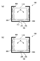
図1(a)において、本形態の振れ補正機能付きの光学ユニット100は、固定体200と、レンズおよび撮像素子などの光学素子を保持する可動モジュール10(撮像ユニット1)と、可動モジュール10を揺動可能に支持する揺動支点180と、揺動支点180を中心に可動モジュール10を揺動させる振れ補正用駆動機構500とを有している。可動モジュール10と固定体200との間には、可動モジュール10を固定体200の底部に向けて付勢するバネ部材600が設けられており、揺動支点180を構成する部材同士は密着した状態にある。   In FIG. 1A, an optical unit 100 with a shake correction function of this embodiment includes a fixed body 200, a movable module 10 (imaging unit 1) that holds optical elements such as a lens and an imaging element, and the movable module 10. A swing fulcrum 180 that is swingably supported and a shake correction drive mechanism 500 that swings the movable module 10 about the swing fulcrum 180 are provided. A spring member 600 that biases the movable module 10 toward the bottom of the fixed body 200 is provided between the movable module 10 and the fixed body 200, and the members constituting the swing fulcrum 180 are in close contact with each other. It is in.

かかる光学ユニット100において、光学ユニット100に手振れなどの振れが発生したとき、かかる振れをセンサ(図示せず)が検出し、かかるセンサの検出結果に基づいて振れ補正駆動機構500を制御する。その結果、振れ補正駆動機構500は、矢印Rで示すように、揺動支点180を中心に可動モジュール10を揺動させるため、光学ユニット100の振れに起因する可動モジュール10の振れを補正することができる。 In such an optical unit 100, when the vibration of the camera shake or the like in the optical unit 100 is generated, such a vibration sensor (not shown) detects and controls the correction drive mechanism 500 swing on the basis of the detection result of the sensor. As a result, the shake correction drive mechanism 500, as indicated by an arrow R, for swinging the movable module 10 around the swing support point 180, to correct the shake of the movable module 10 due to the deflection of the optical unit 100 be able to.

ここで、揺動支点180は、可動モジュール10の底部と固定体200の底部との間において2つの部材の光軸方向での接触部分により構成され、ピボット軸受と同様な構成を有している。より具体的には、まず、固定体200の底部には穴711が形成されており、かかる穴711によって鋼球181(球体)が保持されている。鋼球181は、凸状に湾曲した部分により可動モジュール10の底部に接しており、可動モジュール10は、可動モジュール10と鋼球181との接触部分を支点にして揺動可能である。本形態では、可動モジュール10の底部は、可動モジュール本体に接着固定された支持板183からなり、かかる支持板183と鋼球181とによって揺動支点180が構成されている。   Here, the oscillating fulcrum 180 is configured by a contact portion in the optical axis direction of two members between the bottom of the movable module 10 and the bottom of the fixed body 200, and has the same configuration as the pivot bearing. . More specifically, first, a hole 711 is formed in the bottom of the fixed body 200, and the steel ball 181 (sphere) is held by the hole 711. The steel ball 181 is in contact with the bottom of the movable module 10 by a convexly curved portion, and the movable module 10 can swing around a contact portion between the movable module 10 and the steel ball 181 as a fulcrum. In this embodiment, the bottom of the movable module 10 is composed of a support plate 183 that is bonded and fixed to the movable module main body, and the support plate 183 and the steel ball 181 constitute a swing fulcrum 180.

また、本形態の光学ユニット100において、互いに接して揺動支点180を構成する2つの部材(支持板183および鋼球181)のうち、支持板183は、ゴムあるいは多孔性エラストマー(ゴムあるいは樹脂)などといった弾性材料からなる。   In the optical unit 100 of the present embodiment, of the two members (the support plate 183 and the steel ball 181) constituting the swing fulcrum 180 in contact with each other, the support plate 183 is a rubber or a porous elastomer (rubber or resin). Made of elastic material.

このように構成した振れ補正機能付き光学ユニット100では、可動モジュール10の底部と固定体200の底部との間において2つの部材(支持板183および鋼球181)の光軸方向での接触部分により構成された揺動支点180を利用しているため、可動モジュール10を揺動させる際、揺動支点180を構成する部材を変形させる必要がない。従って、可動モジュール10を小さな力で揺動させることができる。   In the optical unit 100 with the shake correction function configured as described above, the contact portion in the optical axis direction between the two members (the support plate 183 and the steel ball 181) is provided between the bottom of the movable module 10 and the bottom of the fixed body 200. Since the configured swing fulcrum 180 is used, it is not necessary to deform the members constituting the swing fulcrum 180 when the movable module 10 is swung. Therefore, the movable module 10 can be swung with a small force.

また、本形態では、揺動支点180を構成する2つの部材(支持板183および鋼球181)のうち、支持板183が弾性材料からなるため、衝撃が加わった際、衝撃を弾性材料からなる支持板183により吸収できる。また、弾性材料からなる部材(支持板183)であれば、バネと違って、振動エネルギーを熱エネルギーに変換して吸収する。従って、可動モジュール10と固定体200との間で共振が発生しにくい。それ故、共振によって可動モジュール10と固定体200との相対的な位置関係が変化し続けるという事態を回避することができるため、サーボ制御を行った場合、制御ゲインを高めても制御系が発振することを防止することができる。例えば、可動モジュール10の底部と固定体200の底部との間において、フォトリフレクタ(図示せず)により可動モジュール10の変位を検出し、かかる検出結果に基づいて、振れ補正駆動機構500を制御する場合でも、振れ補正駆動機構500を適正に制御することができる。 Moreover, in this embodiment, since the support plate 183 is made of an elastic material among the two members (the support plate 183 and the steel ball 181) constituting the swing fulcrum 180, the impact is made of an elastic material when an impact is applied. It can be absorbed by the support plate 183. Further, in the case of a member made of an elastic material (support plate 183), unlike a spring, vibration energy is converted into heat energy and absorbed. Therefore, resonance hardly occurs between the movable module 10 and the fixed body 200. Therefore, a situation in which the relative positional relationship between the movable module 10 and the fixed body 200 continues to change due to resonance can be avoided. Therefore, when servo control is performed, the control system oscillates even if the control gain is increased. Can be prevented. For example, between the bottom of the bottom portion and the fixed body 200 of the movable module 10, detects the displacement of the movable module 10 by the photo-reflector (not shown), on the basis of the detection result, controls the shake correction drive mechanism 500 even when it is possible to properly control the shake correction drive mechanism 500.

また、揺動支点180を構成する2つの部材(支持板183および鋼球181)のうち、一方の部材(鋼球181)は、凸状に湾曲した部分で他方の部材(支持板183)に接している。このため、揺動支点180は、可動モジュール10が揺動する方向にかかわら
ず、均等に支持することができる。また、湾曲した形状であれば、衝撃を効果的に吸収するので、2つの部材(支持板183および鋼球181)のうち、一方のみが弾性材料からなる構成を採用することができる。なお、揺動支点180を構成する2つの部材(支持板183および鋼球181)の双方を弾性材料により構成してもよい。
Further, of the two members (support plate 183 and steel ball 181) constituting the swing fulcrum 180, one member (steel ball 181) is a convexly curved portion to the other member (support plate 183). It touches. For this reason, the swing fulcrum 180 can be supported evenly regardless of the direction in which the movable module 10 swings. Moreover, since it will absorb an impact effectively if it is a curved shape, the structure which only one side consists of an elastic material is employable among two members (the support plate 183 and the steel ball 181). Note that both of the two members (support plate 183 and steel ball 181) constituting the swing fulcrum 180 may be made of an elastic material.

また、可動モジュール10と固定体200との間には、可動モジュール10を固定体200の底部に向けて付勢するバネ部材600が設けられている。このため、可動モジュール10側と固定体200側とが密に接する状態となるので、可動モジュール10の共振を防止することができる。   A spring member 600 that biases the movable module 10 toward the bottom of the fixed body 200 is provided between the movable module 10 and the fixed body 200. For this reason, since the movable module 10 side and the fixed body 200 side are in close contact with each other, resonance of the movable module 10 can be prevented.

なお、図1(a)に示す形態では、可動モジュール10側の支持板183と、固定体200の底部側に位置する鋼球181とによって揺動支点180を構成したが、図1(b)に示すように、固定体200の底部から可動モジュール10に向けて湾曲した先端部をもって突出した凸部186と支持板183とにより揺動支点180を構成してもよい。   In the form shown in FIG. 1A, the swing fulcrum 180 is configured by the support plate 183 on the movable module 10 side and the steel ball 181 located on the bottom side of the fixed body 200, but FIG. As shown in FIG. 6, the swing fulcrum 180 may be configured by the convex portion 186 and the support plate 183 that protrude from the bottom portion of the fixed body 200 toward the movable module 10 with a curved tip portion.

かかる構成の場合も、可動モジュール10の底部と固定体200の底部との間において2つの部材(支持板183および凸部186)の光軸方向での接触部分により構成された揺動支点180を利用しているため、可動モジュール10を揺動させる際、揺動支点180を構成する部材を変形させる必要がない。従って、可動モジュール10を小さな力で揺動させることができる。また、本形態では、揺動支点180を構成する2つの部材(支持板183および凸部186)のうち、支持板183が弾性材料からなるため、衝撃が加わった際、衝撃を弾性材料からなる支持板183により吸収できる。従って、可動モジュール10と固定体200との間で共振が発生しにくい。   Also in such a configuration, the rocking fulcrum 180 formed by the contact portion in the optical axis direction of the two members (the support plate 183 and the convex portion 186) is provided between the bottom of the movable module 10 and the bottom of the fixed body 200. Therefore, when the movable module 10 is swung, it is not necessary to deform the member constituting the swing fulcrum 180. Therefore, the movable module 10 can be swung with a small force. In this embodiment, since the support plate 183 is made of an elastic material among the two members (the support plate 183 and the convex portion 186) constituting the swing fulcrum 180, the impact is made of an elastic material when an impact is applied. It can be absorbed by the support plate 183. Therefore, resonance hardly occurs between the movable module 10 and the fixed body 200.

実施の形態1
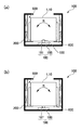
図2は、本発明の実施の形態1に係る振れ補正機能付きの光学ユニットの構成を模式的に示す説明図であり、図2(a)、(b)は、固定体の支持板と鋼球とによって揺動支点を構成した場合の説明図、および固定体の支持板と可動モジュールの半球状の凸部とによって揺動支点を構成した場合の説明図である。なお、本形態および以下に説明する形態はいずれも、基本的な構成が参考例1と同様であるため、共通する部分には同一の符号を付してそれらの説明を省略する。
[ Embodiment 1 ]
FIG. 2 is an explanatory view schematically showing a configuration of an optical unit with a shake correction function according to Embodiment 1 of the present invention, and FIGS. 2 (a) and 2 (b) show a support plate and steel of a fixed body. It is explanatory drawing at the time of comprising a rocking | fluctuation fulcrum with a ball | bowl, and explanatory drawing at the time of comprising a rocking | fluctuation fulcrum with the support plate of a fixed body, and the hemispherical convex part of a movable module. In addition, since the basic configuration is the same as that of Reference Example 1 in both this embodiment and the embodiment described below, common portions are denoted by the same reference numerals, and description thereof is omitted.

図2(a)において、本形態の振れ補正機能付きの光学ユニット100でも、参考例1と同様、固定体200と、レンズおよび撮像素子などの光学素子を保持する可動モジュール10(撮像ユニット1)と、可動モジュール10を揺動可能に支持する揺動支点180と、揺動支点180を中心に可動モジュール10を揺動させる振れ補正用駆動機構500とを有している。かかる光学ユニット100において、光学ユニット100に手振れなどの振れが発生したとき、かかる振れをセンサ(図示せず)が検出し、かかるセンサの検出結果に基づいて振れ補正駆動機構500を制御して、揺動支点180を中心に可動モジュール10を揺動させる。 2A, in the optical unit 100 with a shake correction function of this embodiment as well as the reference example 1 , the movable module 10 (the imaging unit 1) that holds the fixed body 200 and optical elements such as a lens and an imaging element. A swing fulcrum 180 that supports the movable module 10 so as to be swingable, and a shake correction drive mechanism 500 that swings the movable module 10 around the swing fulcrum 180. In such an optical unit 100, when the vibration of the camera shake or the like in the optical unit 100 is generated, such a vibration sensor (not shown) detects, by controlling the correction drive mechanism 500 swing on the basis of the detection result of the sensor The movable module 10 is swung around the swing fulcrum 180.

ここで、揺動支点180は、可動モジュール10の底部と固定体200の底部との間において2つの部材の光軸方向での接触部分により構成されている。より具体的には、まず、可動モジュール10の底部には穴185が形成されており、かかる穴185によって鋼球181が保持されている。鋼球181は、凸状に湾曲した部分により固定体200の底部に接しており、可動モジュール10は、鋼球181と固定体200の底部との接触部分を支点にして揺動可能である。本形態では、固定体200の底部は、固定体本体に接着固定された支持板188からなり、かかる支持板188と鋼球181とによって揺動支点180が構成されている。   Here, the swing fulcrum 180 is configured by a contact portion in the optical axis direction of two members between the bottom of the movable module 10 and the bottom of the fixed body 200. More specifically, first, a hole 185 is formed in the bottom of the movable module 10, and the steel ball 181 is held by the hole 185. The steel ball 181 is in contact with the bottom of the fixed body 200 by a convexly curved portion, and the movable module 10 can swing around the contact portion between the steel ball 181 and the bottom of the fixed body 200 as a fulcrum. In this embodiment, the bottom of the fixed body 200 is composed of a support plate 188 that is bonded and fixed to the main body of the fixed body, and the support plate 188 and the steel ball 181 constitute a swing fulcrum 180.

また、本形態の光学ユニット100において、互いに接して揺動支点180を構成する2つの部材(支持板188および鋼球181)のうち、支持板188は、ゴムあるいは多孔性エラストマー(ゴムあるいは樹脂)などといった弾性材料からなる。   In the optical unit 100 of the present embodiment, of the two members (the support plate 188 and the steel ball 181) constituting the swing fulcrum 180 in contact with each other, the support plate 188 is rubber or porous elastomer (rubber or resin). Made of elastic material.

従って、本形態の振れ補正機能付き光学ユニット100でも、参考例1と同様、可動モジュール10の底部と固定体200の底部との間において2つの部材(支持板188および鋼球181)の光軸方向での接触部分により構成された揺動支点180を利用しているため、可動モジュール10を揺動させる際、揺動支点180を構成する部材を変形させる必要がない。従って、可動モジュール10を小さな力で揺動させることができる。また、本形態では、揺動支点180を構成する2つの部材(支持板188および鋼球181)のうち、支持板188が弾性材料からなるため、衝撃が加わった際、衝撃を弾性材料からなる支持板188により吸収できる。また、弾性材料からなる部材(支持板188)であれば、バネと違って、振動エネルギーを熱エネルギーに変換して吸収する。従って、可動モジュール10と固定体200との間で共振が発生しにくい。 Therefore, also in the optical unit 100 with shake correction function of this embodiment, the optical axes of the two members (the support plate 188 and the steel ball 181) between the bottom of the movable module 10 and the bottom of the fixed body 200, as in Reference Example 1. Since the swing fulcrum 180 constituted by the contact portion in the direction is used, it is not necessary to deform the member constituting the swing fulcrum 180 when the movable module 10 is swung. Therefore, the movable module 10 can be swung with a small force. In this embodiment, since the support plate 188 is made of an elastic material among the two members (the support plate 188 and the steel ball 181) constituting the swing fulcrum 180, the impact is made of an elastic material when an impact is applied. It can be absorbed by the support plate 188. Further, in the case of a member made of an elastic material (support plate 188), unlike a spring, vibration energy is converted into heat energy and absorbed. Therefore, resonance hardly occurs between the movable module 10 and the fixed body 200.

また、揺動支点180を構成する2つの部材(支持板188および鋼球181)のうち、一方の部材(鋼球181)は、凸状に湾曲した部分で他方の部材(支持板188)に接している。このため、揺動支点180は、可動モジュール10が揺動する方向にかかわらず、均等に支持することができる。また、湾曲した形状であれば、衝撃を効果的に吸収するので、2つの部材(支持板188および鋼球181)のうち、一方のみが弾性材料からなる構成を採用することができるなど、参考例1と同様な効果を奏する。 Further, of the two members (support plate 188 and steel ball 181) constituting the swing fulcrum 180, one member (steel ball 181) is a convexly curved portion to the other member (support plate 188). It touches. For this reason, the swing fulcrum 180 can be supported evenly regardless of the direction in which the movable module 10 swings. Further, if the curved shape, so effectively absorb the shock, one of the two members (the support plate 188 and steel balls 181), etc. can be only one to adopt a structure made of an elastic material, reference The same effect as Example 1 is produced.

なお、図2(a)に示す形態では、固定体200側の支持板188と、可動モジュール10の底部に位置する鋼球181とによって揺動支点180を構成したが、図2(b)に示すように、可動モジュール10の底部から固定体200に向けて湾曲した先端部をもって突出した凸部187と、支持板188とにより揺動支点180を構成してもよい。   In the form shown in FIG. 2A, the swing fulcrum 180 is configured by the support plate 188 on the fixed body 200 side and the steel ball 181 located at the bottom of the movable module 10, but in FIG. As shown, the swing fulcrum 180 may be constituted by a convex portion 187 that protrudes with a tip end curved toward the fixed body 200 from the bottom of the movable module 10 and a support plate 188.

かかる構成の場合も、可動モジュール10の底部と固定体200の底部との間において2つの部材(支持板188および凸部187)の光軸方向での接触部分により構成された揺動支点180を利用しているため、可動モジュール10を揺動させる際、揺動支点180を構成する部材を変形させる必要がない。従って、可動モジュール10を小さな力で揺動させることができる。また、本形態では、揺動支点180を構成する2つの部材(支持板188および凸部187)のうち、支持板188が弾性材料からなるため、衝撃が加わった際、衝撃を弾性材料からなる支持板188により吸収できる。また、弾性材料からなる部材(支持板188)であれば、バネと違って、振動エネルギーを熱エネルギーに変換して吸収する。従って、可動モジュール10と固定体200との間で共振が発生しにくいなど、参考例1と同様な効果を奏する。 Also in such a configuration, the rocking fulcrum 180 formed by the contact portion in the optical axis direction of the two members (the support plate 188 and the convex portion 187) is provided between the bottom of the movable module 10 and the bottom of the fixed body 200. Therefore, when the movable module 10 is swung, it is not necessary to deform the member constituting the swing fulcrum 180. Therefore, the movable module 10 can be swung with a small force. In this embodiment, since the support plate 188 is made of an elastic material among the two members (the support plate 188 and the convex portion 187) constituting the swing fulcrum 180, the impact is made of an elastic material when an impact is applied. It can be absorbed by the support plate 188. Further, in the case of a member made of an elastic material (support plate 188), unlike a spring, vibration energy is converted into heat energy and absorbed. Accordingly, the same effects as those of the reference example 1 can be obtained, such that resonance does not easily occur between the movable module 10 and the fixed body 200.

参考例2
図3は、参考例2に係る振れ補正機能付きの光学ユニットの構成を模式的に示す説明図であり、図3(a)、(b)は、可動モジュールの支持板と球体とによって揺動支点を構成した場合の説明図、および固定体の支持板と球体とによって揺動支点を構成した場合の説明図である。
[ Reference Example 2 ]
FIGS. 3A and 3B are explanatory views schematically showing a configuration of an optical unit with a shake correction function according to Reference Example 2 , and FIGS. 3A and 3B are swung by a support plate and a sphere of the movable module. It is explanatory drawing at the time of comprising a fulcrum, and explanatory drawing at the time of comprising a rocking fulcrum with the support plate and sphere of a fixed body.

図3(a)において、本形態の振れ補正機能付きの光学ユニット100も、図1(a)を参照して説明した形態と同様、揺動支点180は、可動モジュール10の底部と固定体200の底部との間において2つの部材の光軸方向での接触部分により構成されている。より具体的には、まず、固定体200の底部には穴711が形成されており、かかる穴711によって球体184が保持されている。球体184は、凸状に湾曲した部分により可動モジュール10の底部に接しており、可動モジュール10は、可動モジュール10と球
体184との接触部分を支点にして揺動可能である。本形態では、可動モジュール10の底部は、可動モジュール本体に接着固定された支持板183からなり、かかる支持板183と球体184とによって揺動支点180が構成されている。
3A, in the optical unit 100 with a shake correction function of the present embodiment, the swing fulcrum 180 has the bottom of the movable module 10 and the fixed body 200 as in the embodiment described with reference to FIG. It is comprised by the contact part in the optical axis direction of two members between the bottom parts. More specifically, first, a hole 711 is formed in the bottom of the fixed body 200, and the sphere 184 is held by the hole 711. The spherical body 184 is in contact with the bottom of the movable module 10 by a convexly curved portion, and the movable module 10 can swing around a contact portion between the movable module 10 and the spherical body 184 as a fulcrum. In this embodiment, the bottom of the movable module 10 is composed of a support plate 183 bonded and fixed to the movable module main body, and the support plate 183 and the sphere 184 constitute a swing fulcrum 180.

ここで、支持板183は金属板など剛性基板であるのに対して、球体184は、ゴムあるいは多孔性エラストマー(ゴムあるいは樹脂)などといった弾性材料からなる。従って、衝撃が加わった際、衝撃を弾性材料からなる球体184により吸収できる。また、弾性材料からなる部材(球体184)であれば、バネと違って、振動エネルギーを熱エネルギーに変換して吸収する。従って、可動モジュール10と固定体200との間で共振が発生しにくいなど、参考例1と同様な効果を奏する。 Here, the support plate 183 is a rigid substrate such as a metal plate, while the sphere 184 is made of an elastic material such as rubber or porous elastomer (rubber or resin). Therefore, when an impact is applied, the impact can be absorbed by the sphere 184 made of an elastic material. Further, in the case of a member made of an elastic material (sphere 184), unlike a spring, vibration energy is converted into heat energy and absorbed. Accordingly, the same effects as those of the reference example 1 can be obtained, such that resonance does not easily occur between the movable module 10 and the fixed body 200.

なお、図3(a)に示す形態では、可動モジュール10側の支持板183と、弾性材料からなる球体184とによって揺動支点180を構成したが、図3(b)に示すように、固定体200側の支持板188(剛性基板)と、弾性材料からなる球体184とによって揺動支点180を構成してもよい。   In the form shown in FIG. 3A, the swing fulcrum 180 is configured by the support plate 183 on the movable module 10 side and the sphere 184 made of an elastic material. However, as shown in FIG. The swing fulcrum 180 may be configured by the support plate 188 (rigid substrate) on the body 200 side and the sphere 184 made of an elastic material.

参考例1の具体的構成例]
以下の説明においては、可動モジュール10として撮像ユニット1の手振れを防止するための構成を例示する。また、以下の説明では、互いに直交する3方向を各々X軸、Y軸、Z軸とし、光軸L(レンズ光軸)に沿う方向をZ軸とする。また、以下の説明では、各方向の振れのうち、X軸周りの回転は、いわゆるピッチング(縦揺れ)に相当し、Y軸周りの回転は、いわゆるヨーイング(横揺れ)に相当し、Z軸周りの回転は、いわゆるローリングに相当する。また、X軸の一方側には+Xを付し、他方側には−Xを付し、Y軸の一方側には+Yを付し、他方側には−Yを付し、Z軸の一方側(被写体側とは反対側)には+Zを付し、他方側(被写体側)には−Zを付して説明する。なお、以下に説明した形態は、図1(a)を参照して説明した形態に対応するが、図1(b)、図2(a)、(b)および図3(a)、(b)を参照して説明した形態も略同様に構成することができる。
[Specific Configuration Example of Reference Example 1 ]
In the following description, a configuration for preventing camera shake of the imaging unit 1 as the movable module 10 is illustrated. In the following description, three directions orthogonal to each other are defined as an X axis, a Y axis, and a Z axis, respectively, and a direction along the optical axis L (lens optical axis) is defined as a Z axis. Further, in the following description, among the shakes in each direction, rotation around the X axis corresponds to so-called pitching (pitch), rotation around the Y axis corresponds to so-called yawing (roll), and Z axis The rotation around corresponds to so-called rolling. Also, + X is attached to one side of the X axis, -X is attached to the other side, + Y is attached to one side of the Y axis, -Y is attached to the other side, and one side of the Z axis is attached. In the following description, + Z is attached to the side (opposite the subject side), and -Z is attached to the other side (subject side). In addition, although the form demonstrated below respond | corresponds to the form demonstrated with reference to Fig.1 (a), FIG.1 (b), FIG.2 (a), (b) and FIG.3 (a), (b) The configuration described with reference to) can be configured in substantially the same manner.

(撮影用の光学ユニットの全体構成)
図4は、参考例1に係る振れ補正機能付きの光学ユニットを携帯電話機等の光学機器に搭載した様子を模式的に示す説明図である。図5は、参考例1に係る振れ補正機能付きの光学ユニットの外観等を示す斜視図であり、図5(a)、(b)は、光学ユニットを被写体側からみたときの斜視図、および光学ユニットを被写体側と反対側からみたときの斜視図である。
(Overall configuration of optical unit for shooting)
FIG. 4 is an explanatory diagram schematically illustrating a state in which the optical unit with a shake correction function according to Reference Example 1 is mounted on an optical device such as a mobile phone. FIG. 5 is a perspective view showing an external appearance or the like of an optical unit with a shake correction function according to Reference Example 1 , and FIGS. 5A and 5B are perspective views of the optical unit when viewed from the subject side. It is a perspective view when an optical unit is seen from a subject side.

図4に示す光学ユニット100(振れ補正機能付き光学ユニット)は、カメラ付き携帯電話機等の光学機器1000に用いられる薄型カメラであって、光学機器1000のシャーシ1100(機器本体)に支持された状態で搭載される。かかる光学ユニット100では、撮影時に光学機器1000に手振れ等の振れが発生すると、撮像画像に乱れが発生する。そこで、本形態の光学ユニット100には、後述するように、撮像ユニット1からなる可動モジュールを固定体200内で揺動可能に支持するとともに、光学ユニット100に搭載したジャイロスコープ(図示せず)、あるいは光学機器1000の本体側に搭載したジャイロスコープ(図示せず)等の振れ検出センサによって手振れを検出した結果に基づいて、撮像ユニット1を揺動させる振れ補正用駆動機構(図4では図示せず)が設けられている。   An optical unit 100 (an optical unit with a shake correction function) shown in FIG. 4 is a thin camera used in an optical device 1000 such as a mobile phone with a camera, and is supported by a chassis 1100 (device main body) of the optical device 1000. It is mounted with. In such an optical unit 100, when a shake such as a hand shake occurs in the optical apparatus 1000 during shooting, the captured image is disturbed. Therefore, in the optical unit 100 of the present embodiment, as will be described later, a movable module including the imaging unit 1 is supported so as to be swingable within the fixed body 200, and a gyroscope (not shown) mounted on the optical unit 100 is supported. Alternatively, based on the result of detecting hand shake by a shake detection sensor such as a gyroscope (not shown) mounted on the main body side of the optical device 1000, a shake correction drive mechanism (shown in FIG. 4) swings the imaging unit 1. Not shown).

図4および図5に示すように、光学ユニット100には、撮像ユニット1や振れ補正用駆動機構への給電等行うためのフレキシブル配線基板410、420が引き出されており、かかるフレキシブル配線基板410、420は、共通のコネクタ490等を介して光学機器1000の本体側に設けられた上位の制御部等に電気的に接続されている。また、フ
レキシブル配線基板410は、撮像ユニット1から信号を出力する機能も担っている。このため、フレキシブル配線基板410は、配線数が多いので、フレキシブル配線基板410としては、比較的幅広のものが使用されている。
As shown in FIGS. 4 and 5, flexible wiring boards 410 and 420 for feeding power to the imaging unit 1 and the shake correction drive mechanism are drawn out from the optical unit 100. Reference numeral 420 is electrically connected to an upper control unit or the like provided on the main body side of the optical apparatus 1000 via a common connector 490 or the like. The flexible wiring board 410 also has a function of outputting a signal from the imaging unit 1. For this reason, since the flexible wiring board 410 has a large number of wires, a flexible wiring board 410 having a relatively wide width is used.

(撮像ユニット1の構成)
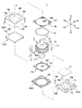
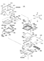
図6は、参考例1に係る振れ補正機能付きの光学ユニット100に搭載されている撮像ユニット1の構成を模式的に示す断面図である。図7は、参考例1に係る振れ補正機能付きの光学ユニット100に搭載されている撮像ユニット1の分解斜視図である。
(Configuration of the imaging unit 1)
FIG. 6 is a cross-sectional view schematically showing a configuration of the imaging unit 1 mounted on the optical unit 100 with a shake correction function according to Reference Example 1 . FIG. 7 is an exploded perspective view of the imaging unit 1 mounted on the optical unit 100 with a shake correction function according to Reference Example 1 .

図6および図7に示すように、撮像ユニット1は、例えば、光学素子としての複数枚のレンズ1a(図4参照)を光軸L方向に沿って被写体(物体側)に近づくA方向(前側)、および被写体とは反対側(撮像素子側/像側)に近づくB方向(後側)の双方向に移動させる光学素子ユニットであり、略直方体形状を有している。撮像ユニット1は、概ね、複数枚のレンズ1a(図4参照)および固定絞り等の光学素子を内側に保持した移動体3と、この移動体3を光軸L方向に沿って移動させるレンズ駆動機構5と、レンズ駆動機構5および移動体3等が搭載された支持体2とを有している。移動体3は、レンズ1aおよび固定絞り(図示せず)を保持する円筒状のレンズホルダ12と、レンズホルダ12を内側に保持するコイルホルダ13とを備えており、コイルホルダ13の外周側面には、レンズ駆動機構5を構成するレンズ駆動用コイル30s、30tが保持されている。   As shown in FIGS. 6 and 7, for example, the imaging unit 1 includes a plurality of lenses 1a (see FIG. 4) as optical elements in the A direction (front side) approaching the subject (object side) along the optical axis L direction. ), And an optical element unit that moves in both directions in the B direction (rear side) approaching the side opposite to the subject (imaging element side / image side), and has a substantially rectangular parallelepiped shape. The imaging unit 1 generally includes a moving body 3 that holds a plurality of lenses 1a (see FIG. 4) and an optical element such as a fixed aperture inside, and a lens drive that moves the moving body 3 along the optical axis L direction. It has a mechanism 5 and a support 2 on which a lens driving mechanism 5 and a moving body 3 are mounted. The moving body 3 includes a cylindrical lens holder 12 that holds a lens 1 a and a fixed diaphragm (not shown), and a coil holder 13 that holds the lens holder 12 on the inner side. The lens driving coils 30s and 30t constituting the lens driving mechanism 5 are held.

支持体2は、被写体側(−Z側)とは反対側で、後述するバネを保持するバネホルダ19と、バネホルダ19に対して被写体側(−Z側)とは反対側で実装基板15を位置決めする矩形板状の基板ホルダ16と、バネホルダ19に対して被写体側で被さる箱状のケース18と、ケース18の内側に配置される矩形板状のスペーサー11とを備えており、実装基板15において被写体側に向く基板面151には撮像素子1bが実装されている。また、バネホルダ19には、赤外線フィルタ等のフィルタ1cが保持されている。スペーサー11およびケース18の中央には、被写体からの光をレンズ1aに取り込むための入射窓11a、18aが各々形成されている。また、基板ホルダ16およびバネホルダ19の中央には、入射光を撮像素子1bに導く窓16a、19aが形成されている。   The support 2 is opposite to the subject side (−Z side), and a mounting holder 15 is positioned on the opposite side of the subject side (−Z side) with respect to the spring holder 19 and a spring holder 19 that holds a spring described later. A rectangular plate-shaped substrate holder 16, a box-shaped case 18 that covers the spring holder 19 on the subject side, and a rectangular plate-shaped spacer 11 that is disposed inside the case 18. An image sensor 1b is mounted on the substrate surface 151 facing the subject. The spring holder 19 holds a filter 1c such as an infrared filter. In the center of the spacer 11 and the case 18, incident windows 11a and 18a for taking in light from the subject into the lens 1a are formed. In addition, windows 16a and 19a for guiding incident light to the image sensor 1b are formed in the center of the substrate holder 16 and the spring holder 19.

ケース18は、鋼板等の強磁性板からなり、ヨークとしても機能する。このため、ケース18は、後述するレンズ駆動用マグネット17とともに、レンズ駆動用コイル30s、30tに鎖交する磁界を発生させる鎖交磁界発生体を構成しており、かかる鎖交磁界発生体は、コイルホルダ13の外周面に巻回されたレンズ駆動用コイル30s、30tとともにレンズ駆動機構5を構成している。   The case 18 is made of a ferromagnetic plate such as a steel plate and also functions as a yoke. For this reason, the case 18 constitutes a linkage magnetic field generator that generates a magnetic field interlinking the lens drive coils 30s and 30t together with the lens drive magnet 17 described later. The lens driving mechanism 5 is configured together with the lens driving coils 30 s and 30 t wound around the outer peripheral surface of the coil holder 13.

支持体2と移動体3とは、光軸方向で離間する位置に設けられた金属製のバネ部材14sと、バネ部材14tとを介して接続されている。本形態では、撮像素子1bの側にはバネ部材14sが用いられ、被写体の側にはバネ部材14tが用いられている。バネ部材14s、14tは基本的な構成が同様であり、支持体2側に保持される外周側連結部141と、移動体3の側に保持される円環状の内周側連結部142と、外周側連結部141と内周側連結部142とを接続する細幅のアーム部143とを備えている。撮像素子1b側のバネ部材14sは、バネホルダ19に外周側連結部141が保持され、内周側連結部142が移動体3のコイルホルダ13の撮像素子側端部に連結されている。かかるバネ部材14sにおいて、アーム部143は、周方向に円弧状に延在している。被写体側のバネ部材14tは、スペーサー11に外周側連結部141が保持され、内周側連結部142が移動体3のコイルホルダ13の被写体側端部に連結されている。かかるバネ部材14tにおいて、アーム部143は、径方向において蛇行しながら周方向に円弧状に延在している。このような構成により、移動体3は、バネ部材14s、14tを介して支持体2に光軸の方向に移動可能に支持されている。バネ部材14s、14tはいずれも、ベリリウム銅や非
磁性のSUS系鋼材等といった非磁性の金属製であり、所定厚の薄板に対するプレス加工、あるいはフォトリソグラフィ技術を用いたエッチング加工により形成したものである。バネ部材14sは、2つのバネ片に2分割されており、レンズ駆動用コイル30s、30tの各端末は各々、バネ片に接続される。また、バネ部材14sにおいて、2つのバネ片には各々、端子14a、14bが接続されており、バネ部材14sはレンズ駆動用コイル30s、30tに対する給電部材としても機能する。
The support body 2 and the moving body 3 are connected to each other via a spring member 14t and a metal spring member 14s provided at positions separated in the optical axis direction. In this embodiment, a spring member 14s is used on the imaging element 1b side, and a spring member 14t is used on the subject side. The spring members 14 s and 14 t have the same basic configuration, and an outer peripheral side connecting portion 141 held on the support body 2 side, an annular inner peripheral side connecting portion 142 held on the movable body 3 side, A narrow arm portion 143 that connects the outer peripheral side connecting portion 141 and the inner peripheral side connecting portion 142 is provided. In the spring member 14 s on the imaging element 1 b side, the outer peripheral side connecting part 141 is held by the spring holder 19, and the inner peripheral side connecting part 142 is connected to the imaging element side end of the coil holder 13 of the moving body 3. In the spring member 14s, the arm portion 143 extends in an arc shape in the circumferential direction. In the subject-side spring member 14 t, the outer peripheral side connecting portion 141 is held by the spacer 11, and the inner peripheral side connecting portion 142 is connected to the subject side end of the coil holder 13 of the moving body 3. In the spring member 14t, the arm portion 143 extends in an arc shape in the circumferential direction while meandering in the radial direction. With such a configuration, the moving body 3 is supported by the support body 2 via the spring members 14s and 14t so as to be movable in the direction of the optical axis. The spring members 14s and 14t are both made of nonmagnetic metal such as beryllium copper or nonmagnetic SUS steel, and are formed by pressing a thin plate having a predetermined thickness or etching using a photolithography technique. is there. The spring member 14s is divided into two spring pieces, and each end of the lens driving coils 30s and 30t is connected to the spring piece. In the spring member 14s, terminals 14a and 14b are connected to the two spring pieces, respectively, and the spring member 14s also functions as a power supply member for the lens driving coils 30s and 30t.

コイルホルダ13の被写体側端部にはリング状の磁性片61が保持されており、かかる磁性片61の位置は、レンズ駆動用マグネット17に対して被写体側の位置である。このため、磁性片61は、レンズ駆動用マグネット17との間に作用する吸引力により移動体3に対して光軸Lの方向の付勢力を印加する。このため、非通電時(原点位置)においてはレンズ駆動用マグネット17と磁性片61との吸引力によってレンズホルダ12を撮像素子1b側に静置することができる。また、磁性片61は、一種のヨークとして作用し、レンズ駆動用マグネット17とレンズ駆動用コイル30s、30tとの間に構成される磁路からの漏れ磁束を少なくすることができる。磁性片61としては、棒状あるいは球状の磁性体が用いられることもある。磁性片61をリング形状にすれば、レンズホルダ12が光軸方向に移動する際にレンズ駆動用マグネット17と引き合う吸引力が等方的になるという効果がある。さらに、レンズ駆動用コイル30s、30tに対する通電時、磁性片61はレンズ駆動用マグネット17から離間する方向に移動するので、撮像素子1b側にレンズホルダ12を押し付けるような余計な力は働かない。そのため、少ない電力でレンズホルダ12を光軸方向に移動させることができる。   A ring-shaped magnetic piece 61 is held at the subject side end of the coil holder 13, and the position of the magnetic piece 61 is a position on the subject side with respect to the lens driving magnet 17. For this reason, the magnetic piece 61 applies a biasing force in the direction of the optical axis L to the moving body 3 by an attractive force acting between the magnetic piece 61 and the lens driving magnet 17. For this reason, at the time of non-energization (origin position), the lens holder 12 can be placed still on the image sensor 1b side by the attractive force of the lens driving magnet 17 and the magnetic piece 61. Further, the magnetic piece 61 acts as a kind of yoke, and can reduce leakage magnetic flux from a magnetic path formed between the lens driving magnet 17 and the lens driving coils 30s and 30t. As the magnetic piece 61, a rod-like or spherical magnetic body may be used. If the magnetic piece 61 is formed in a ring shape, there is an effect that the attractive force attracting the lens driving magnet 17 when the lens holder 12 moves in the optical axis direction is isotropic. Further, when the lens driving coils 30 s and 30 t are energized, the magnetic piece 61 moves in a direction away from the lens driving magnet 17, so that no extra force is exerted to press the lens holder 12 toward the image sensor 1 b. Therefore, the lens holder 12 can be moved in the optical axis direction with a small amount of electric power.

本形態の撮像ユニット1において、光軸Lの方向からみたとき、レンズ1a(図4参照)は円形であるが、支持体2に用いたケース18は矩形箱状である。従って、ケース18は、角筒状胴部18cを備えており、角筒状胴部18cの上面側には、入射窓18aが形成された上板部18bを備えている。角筒状胴部18cの内側において、四角形の角に相当する側面部にはレンズ駆動用マグネット17が固着されており、かかるレンズ駆動用マグネット17は各々、三角柱状の永久磁石からなる。4つのレンズ駆動用マグネット17はいずれも光軸の方向において2分割されており、いずれにおいても内面と外面とが異なる極に着磁されている。このため、コイルホルダ13の周りにおいて、2つのレンズ駆動用コイル30s、30tにおける巻回方向は反対である。このように構成した移動体3は、ケース18の内側に配置される。その結果、レンズ駆動用コイル30s、30tは各々、ケース18の角筒状胴部18cの内面に固着されたレンズ駆動用マグネット17に対向して、レンズ駆動機構5を構成することになる。   In the imaging unit 1 of the present embodiment, when viewed from the direction of the optical axis L, the lens 1a (see FIG. 4) is circular, but the case 18 used for the support 2 has a rectangular box shape. Accordingly, the case 18 includes a rectangular tube-shaped body portion 18c, and an upper plate portion 18b having an incident window 18a formed on the upper surface side of the rectangular tube-shaped body portion 18c. A lens driving magnet 17 is fixed to a side surface corresponding to a square corner inside the rectangular cylindrical body portion 18c, and each of the lens driving magnets 17 is composed of a triangular prism-like permanent magnet. Each of the four lens driving magnets 17 is divided into two in the direction of the optical axis, and in any case, the inner surface and the outer surface are magnetized to different poles. For this reason, the winding directions of the two lens driving coils 30 s and 30 t are opposite to each other around the coil holder 13. The moving body 3 configured as described above is disposed inside the case 18. As a result, the lens driving coils 30 s and 30 t each constitute the lens driving mechanism 5 so as to face the lens driving magnet 17 fixed to the inner surface of the rectangular tubular body 18 c of the case 18.

このように構成した撮像ユニット1において、移動体3は、通常は撮像素子側(Z軸方向の一方側)に位置しており、このような状態において、レンズ駆動用コイル30s、30tに所定方向の電流を流すと、レンズ駆動用コイル30s、30tは、それぞれ被写体側(Z軸方向の他方側)に向かう電磁力を受けることになる。これにより、レンズ駆動用コイル30s、30tが固着された移動体3は、被写体側(前側)に移動し始めることになる。このとき、バネ部材14tと移動体3の前端との間、およびバネ部材14sと移動体3の後端との間には、移動体3の移動を規制する弾性力が発生する。このため、移動体3を前側に移動させようとする電磁力と、移動体3の移動を規制する弾性力とが釣り合ったとき、移動体3は停止する。その際、バネ部材14s、14tによって移動体3に働く弾性力に応じて、レンズ駆動用コイル30s、30tに流す電流量を調整することで、移動体3を所望の位置に停止させることができる。   In the imaging unit 1 configured as described above, the moving body 3 is normally located on the imaging element side (one side in the Z-axis direction). In such a state, the moving body 3 is directed to the lens driving coils 30s and 30t in a predetermined direction. When the current is applied, the lens driving coils 30s and 30t each receive an electromagnetic force directed toward the subject side (the other side in the Z-axis direction). Accordingly, the moving body 3 to which the lens driving coils 30s and 30t are fixed starts to move toward the subject side (front side). At this time, an elastic force that restricts the movement of the moving body 3 is generated between the spring member 14 t and the front end of the moving body 3 and between the spring member 14 s and the rear end of the moving body 3. For this reason, when the electromagnetic force which moves the moving body 3 to the front side and the elastic force which regulates the movement of the moving body 3 balance, the moving body 3 stops. At this time, the moving body 3 can be stopped at a desired position by adjusting the amount of current flowing through the lens driving coils 30 s and 30 t according to the elastic force acting on the moving body 3 by the spring members 14 s and 14 t. .

(光学ユニット100の構成)
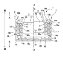
図8は、参考例1に係る振れ補正機能付きの光学ユニット100の内部構造を示す断面図であり、図8(a)、(b)は、光学ユニット100のYZ断面図、および光学ユニッ
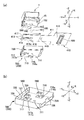
ト100のXZ断面図である。なお、図8では、撮像ユニット1についてはケース18、基板ホルダ16および実装基板15のみを図示し、その他の部材について図示を省略してある。図9は、参考例1に係る振れ補正機能付きの光学ユニット100を被写体側からみたときの分解斜視図であり、図10は、参考例1に係る振れ補正機能付きの光学ユニット100を被写体側とは反対側からみたときの分解斜視図である。
(Configuration of optical unit 100)
8 is a cross-sectional view showing the internal structure of the optical unit 100 with a shake correction function according to Reference Example 1. FIGS. 8A and 8B are a YZ cross-sectional view of the optical unit 100 and the optical unit 100. FIG. It is XZ sectional drawing of. In FIG. 8, only the case 18, the substrate holder 16, and the mounting substrate 15 are illustrated for the imaging unit 1, and the other members are not illustrated. Figure 9 is an exploded perspective view of the optical unit with shake correcting function 100 of according to the reference example 1 as viewed from the subject side, FIG. 10, the object-side optical unit 100 with a shake according to the reference example 1 correction function It is a disassembled perspective view when it sees from the opposite side.

図8、図9および図10において、光学ユニット100は、まず、固定体200と、撮像ユニット1と、撮像ユニット1が固定体200に変位可能に支持された状態とするバネ部材600と、撮像ユニット1と固定体200との間で撮像ユニット1を固定体200に対して相対変位させる磁気駆動力を発生させる振れ補正用駆動機構500とを有している。撮像ユニット1の外周部分は、撮像ユニット1において支持体2に用いたケース18(図7参照)からなる。   8, 9, and 10, the optical unit 100 includes a fixed body 200, an imaging unit 1, a spring member 600 that is supported by the fixed body 200 so as to be displaceable, and an imaging unit. A shake correction drive mechanism 500 that generates a magnetic drive force that causes the imaging unit 1 to be displaced relative to the fixed body 200 between the unit 1 and the fixed body 200 is provided. The outer peripheral portion of the imaging unit 1 is composed of a case 18 (see FIG. 7) used for the support 2 in the imaging unit 1.

固定体200は上カバー250、スペーサー280および下カバー700を備えており、上カバー250は、撮像ユニット1の周りを囲む角筒状胴部210と、角筒状胴部210の被写体側の開口部を塞ぐ端板部220とを備えている。端板部220には、被写体からの光が入射する窓220aが形成されている。上カバー250において、角筒状胴部210は、被写体側(光軸Lが延在している側)とは反対側(+Z側)の端部が開放端になっている。また、角筒状胴部210においてY軸方向で対向する2つの面のうち、Y軸方向の一方側+Yに位置する面には切り欠き219が形成されており、かかる切り欠き219は、フレキシブル配線基板420を、後述するシート状コイル550の端子部と接続する際に利用される。また、角筒状胴部210の4面には、後述するスペーサー280との係合に利用される切り欠き218が形成されており、切り欠き218のうち、Y軸方向に位置する2つの切り欠き218は、切り欠き219と繋がって一体の切り欠きを構成している。また、角筒状胴部210において、Y軸方向で対向する2つ個所の下端側には切り欠き218と繋がった切り欠き217が形成されており、かかる2つの切り欠き217のうち、Y軸方向の一方側+Yの切り欠き217は、フレキシブル配線基板410を外部に引き出すのに利用される。   The fixed body 200 includes an upper cover 250, a spacer 280, and a lower cover 700, and the upper cover 250 includes a rectangular tubular body 210 surrounding the imaging unit 1 and an opening on the subject side of the rectangular tubular body 210. And an end plate part 220 for closing the part. The end plate 220 is formed with a window 220a through which light from the subject enters. In the upper cover 250, the end of the rectangular tubular body 210 opposite to the subject (the side on which the optical axis L extends) (+ Z side) is an open end. In addition, a notch 219 is formed on a surface located on one side + Y in the Y-axis direction of two surfaces facing each other in the Y-axis direction in the rectangular tubular body 210, and the notch 219 is flexible. This is used when the wiring board 420 is connected to a terminal portion of a sheet-like coil 550 described later. Further, notches 218 used for engagement with a spacer 280 described later are formed on the four surfaces of the rectangular tube-shaped body portion 210, and two of the notches 218 located in the Y-axis direction are formed. The notch 218 is connected to the notch 219 to form an integral notch. In addition, in the rectangular tubular body 210, a notch 217 connected to the notch 218 is formed on the lower end side of two locations facing each other in the Y-axis direction. Of the two notches 217, the Y-axis The notch 217 on one side + Y in the direction is used to pull out the flexible wiring board 410 to the outside.

スペーサー280は、上カバー250の角筒状胴部210と下カバー700との間に挟持される四角形の枠部281と、枠部281の角部分から被写体側に向けて突出した柱状部283と、枠部281の辺部分で外側に向けて小さく突出する係合突部285とを備えている。スペーサー280に対して上カバー250を被せた際、上カバー250の角筒状胴部210において四角形状に切り欠かれた切り欠き218に係合突部285が係合して、スペーサー280と上カバー250との位置決めが行われる。   The spacer 280 includes a rectangular frame portion 281 that is sandwiched between the rectangular tubular body 210 of the upper cover 250 and the lower cover 700, and a columnar portion 283 that protrudes from the corner portion of the frame portion 281 toward the subject. , And an engaging protrusion 285 that protrudes outward at the side portion of the frame portion 281. When the upper cover 250 is put on the spacer 280, the engaging protrusion 285 is engaged with the notch 218 cut out in a square shape in the rectangular tube-shaped body 210 of the upper cover 250, and the spacer 280 and the Positioning with the cover 250 is performed.

下カバー700は、金属板に対するプレス加工品であり、略矩形の底板部710と、底板部710の外周縁から被写体側に向けて起立する4つの側板部720とを備えている。かかる下カバー700に対してスペーサー280および上カバー250を重ねた際、側板部720は、上カバー250の角筒状胴部210との間にスペーサー280の枠部281を挟持する。   The lower cover 700 is a press-processed product with respect to a metal plate, and includes a substantially rectangular bottom plate portion 710 and four side plate portions 720 that stand from the outer peripheral edge of the bottom plate portion 710 toward the subject. When the spacer 280 and the upper cover 250 are stacked on the lower cover 700, the side plate part 720 sandwiches the frame part 281 of the spacer 280 between the square cylindrical body part 210 of the upper cover 250.

下カバー700の側板部720のうち、Y軸方向の一方側+Yに位置する側板部720には、切り欠き728が形成されているとともに、かかる切り欠き728の中央部には、側板部720の一部が板状突起729として残されている。また、側板部720のうち、Y軸方向の他方側−Yに位置する側板部720にも窓状の切り欠き726が形成されているとともに、かかる切り欠き726の中央部には、側板部720の一部が桟部727として残されている。かかる切り欠き726、728のうち、切り欠き728は、後述するように、フレキシブル配線基板410を外部に引き出すのに利用され、切り欠き726は、折り返し部分413が下カバー700の側板部720と干渉するのを防止するのに利用さ
れる。
Of the side plate portions 720 of the lower cover 700, a notch 728 is formed in the side plate portion 720 located on one side + Y in the Y-axis direction, and the center portion of the notch 728 has the side plate portion 720. A part is left as a plate-like protrusion 729. Further, among the side plate portions 720, the side plate portion 720 located on the other side −Y in the Y-axis direction is also formed with a window-shaped notch 726, and the side plate portion 720 is formed at the center of the notch 726. Is left as a crosspiece 727. Of the cutouts 726 and 728, the cutout 728 is used to pull out the flexible wiring substrate 410 to the outside, as will be described later. The cutout 726 interferes with the side plate portion 720 of the lower cover 700. It is used to prevent from doing.

下カバー700の底板部710にはその中央位置に穴711が形成されているとともに、穴711に対してX軸方向の他方側−Xで隣接する位置、および穴711に対してY軸方向の他方側−Yで隣接する位置には、矩形形状に凹んだ凹部716、717が形成されている。後述するように、凹部716、717の底部716a、717aの内面は略鏡面になっており、底部716a、717aは、実装基板15において被写体側とは反対側の基板面152に実装された第1フォトリフレクタ580および第2フォトリフレクタ590に対する反射面として利用される。   The bottom plate portion 710 of the lower cover 700 has a hole 711 formed at the center thereof, and is positioned adjacent to the hole 711 on the other side −X in the X-axis direction and to the hole 711 in the Y-axis direction. Concave portions 716 and 717 that are recessed in a rectangular shape are formed at positions adjacent to each other on the other side -Y. As will be described later, the inner surfaces of the bottom portions 716a and 717a of the recesses 716 and 717 are substantially mirror surfaces, and the bottom portions 716a and 717a are first mounted on the substrate surface 152 on the mounting substrate 15 opposite to the subject side. This is used as a reflection surface for the photo reflector 580 and the second photo reflector 590.

かかる下カバー700は、熱処理により非磁性化した金属部品からなる。より具体的には、下カバー700はSUS304等の金属材料を所定形状に曲げ加工や絞り加工等を行なった金属部品からなる。ここで、SUS304等に曲げ加工や絞り加工等を行なうと、オーステナイトの一部がマルテンサイトに転移し磁性をもつが、本形態では、曲げ加工や絞り加工等の後、熱処理を行なって下カバー700を得ている。このため、光学ユニット100を組み立てる際、永久磁石520と下カバー700との吸着等を防止することができる。また、SUS304等の金属材料に熱処理を行うと、反射率が高くなるので、下カバー700は、第1フォトリフレクタ580および第2フォトリフレクタ590に対する反射面として利用するのに十分な反射率を備えている。   The lower cover 700 is made of a metal part that has been made nonmagnetic by heat treatment. More specifically, the lower cover 700 is made of a metal part obtained by bending or drawing a metal material such as SUS304 into a predetermined shape. Here, when bending or drawing or the like is performed on SUS304 or the like, a part of austenite is transferred to martensite and has magnetism, but in this embodiment, the lower cover is subjected to heat treatment after bending or drawing and the like. 700 is earned. For this reason, when the optical unit 100 is assembled, it is possible to prevent the permanent magnet 520 and the lower cover 700 from being attracted. Further, when heat treatment is performed on a metal material such as SUS304, the reflectance increases, so the lower cover 700 has sufficient reflectance to be used as a reflective surface for the first photoreflector 580 and the second photoreflector 590. ing.

(揺動支点の構成)
撮像ユニット1に対してZ軸の一方側+Z(被写体側とは反対側)では、撮像ユニット1と固定体200の下カバー700との間に、撮像ユニット1を揺動させる際の揺動支点180が設けられており、撮像ユニット1は、バネ部材600によって揺動支点180を介して下カバー700に向けて付勢されている。本形態において、揺動支点180は、下カバー700の底板部710に形成された穴711に位置決めされた鋼球181と、実装基板15の基板面152に固着された支持板183とによって構成されており、撮像ユニット1は、鋼球181と支持板183との接触位置を揺動中心にして揺動可能である。
(Configuration of swing fulcrum)
On one side of the Z-axis with respect to the imaging unit 1 + Z (opposite to the subject side), a swing fulcrum for swinging the imaging unit 1 between the imaging unit 1 and the lower cover 700 of the fixed body 200 180 is provided, and the imaging unit 1 is biased toward the lower cover 700 by the spring member 600 via the swing fulcrum 180. In this embodiment, the swing fulcrum 180 is configured by a steel ball 181 positioned in a hole 711 formed in the bottom plate portion 710 of the lower cover 700 and a support plate 183 fixed to the board surface 152 of the mounting board 15. The imaging unit 1 can swing around the position of contact between the steel ball 181 and the support plate 183 as a swing center.

このように、本形態の振れ補正機能付き光学ユニット100では、図1(a)を参照して説明したように、可動モジュール10の底部と固定体200の底部との間において2つの部材(支持板183および鋼球181)の光軸方向での接触部分により構成された揺動支点180が構成されている。ここで、揺動支点180を構成する2つの部材(支持板183および鋼球181)のうち、支持板183は、ゴムなどの弾性材料からなる。   Thus, in the optical unit 100 with shake correction function of the present embodiment, as described with reference to FIG. 1A, two members (supports) are provided between the bottom of the movable module 10 and the bottom of the fixed body 200. A rocking fulcrum 180 constituted by a contact portion of the plate 183 and the steel ball 181) in the optical axis direction is constituted. Here, of the two members (support plate 183 and steel ball 181) constituting the swing fulcrum 180, the support plate 183 is made of an elastic material such as rubber.

(バネ部材600の構成)
バネ部材600は、固定体200において下カバー700の側板部720とスペーサー280の枠部281との間に挟持される固定側連結部620と、撮像ユニット1に連結される可動側連結部610と、可動側連結部610と固定側連結部620の間で延在する複数本のアーム部630とを備えた板状バネ部材であり、アーム部630の両端は各々、可動側連結部610および固定側連結部620に繋がっている。本形態において、バネ部材600の可動側連結部610は、撮像ユニット1の後端側において基板ホルダ16の外周側に形成された段部168に固着されている。かかるバネ部材600は、ベリリウム銅や非磁性のSUS系鋼材等といった非磁性の金属製であり、所定厚の薄板に対するプレス加工、あるいはフォトリソグラフィ技術を用いたエッチング加工により形成したものである。
(Configuration of the spring member 600)
The spring member 600 includes a fixed-side connection portion 620 that is sandwiched between the side plate portion 720 of the lower cover 700 and the frame portion 281 of the spacer 280 in the fixed body 200, and a movable-side connection portion 610 that is connected to the imaging unit 1. The plate-like spring member is provided with a plurality of arm portions 630 extending between the movable side connecting portion 610 and the fixed side connecting portion 620, and both ends of the arm portion 630 are respectively connected to the movable side connecting portion 610 and the fixed portion. It is connected to the side connecting part 620. In this embodiment, the movable side connecting portion 610 of the spring member 600 is fixed to a step portion 168 formed on the outer peripheral side of the substrate holder 16 on the rear end side of the imaging unit 1. The spring member 600 is made of a nonmagnetic metal such as beryllium copper or a nonmagnetic SUS steel material, and is formed by pressing a thin plate having a predetermined thickness or etching using a photolithography technique.

ここで、バネ部材600の固定側連結部620を固定体200において下カバー700の側板部720とスペーサー280の枠部281との間に挟持した状態で、鋼球181より被写体側に撮像ユニット1を配置すると、撮像ユニット1は鋼球181よって被写体側
に押し上げられた状態となる。このため、バネ部材600において、可動側連結部610は固定側連結部620よりも被写体側に押し上げられた状態となり、バネ部材600のアーム部630は、撮像ユニット1を被写体側とは反対側に付勢する。従って、撮像ユニット1は、バネ部材600によって揺動支点180を介して下カバー700の底板部710に向けて付勢された状態になり、撮像ユニット1は、揺動支点180によって揺動可能な状態に固定体200に支持された状態となる。
Here, in a state where the fixed side connecting portion 620 of the spring member 600 is sandwiched between the side plate portion 720 of the lower cover 700 and the frame portion 281 of the spacer 280 in the fixed body 200, the imaging unit 1 is closer to the subject side than the steel ball 181. Is placed, the imaging unit 1 is pushed up to the subject side by the steel ball 181. Therefore, in the spring member 600, the movable side connecting portion 610 is pushed up to the subject side relative to the fixed side connecting portion 620, and the arm portion 630 of the spring member 600 moves the imaging unit 1 to the opposite side to the subject side. Energize. Accordingly, the imaging unit 1 is biased toward the bottom plate portion 710 of the lower cover 700 by the spring member 600 via the swing fulcrum 180, and the imaging unit 1 can swing by the swing fulcrum 180. It will be in the state supported by the fixed body 200 in the state.

(振れ補正用駆動機構の構成)
図8〜図10に示すように、本形態の光学ユニット100では、コイル部560と、コイル部560に鎖交する磁界を発生させる永久磁石520とによって、振れ補正用駆動機構500が構成されている。より具体的には、撮像ユニット1においてケース18の角筒状胴部18cの4つの外面18e、18f、18g、18hには平板状の永久磁石520が各々固定されており、上カバー250の角筒状胴部210の内面211、212、213、214にはコイル部560配置されている。永久磁石520は、外面側および内面側が異なる極に着磁されている。また、永久磁石520は、光軸L方向に配置された2つの磁石片からなり、かかる磁石片は、コイル部560と対向する側の面が異なる極に着磁されている。また、コイル部560は、四角形の枠状に形成されており、上下の長辺部分が有効辺として利用される。
(Configuration of shake correction drive mechanism)
As shown in FIGS. 8 to 10, in the optical unit 100 of this embodiment, the shake correction drive mechanism 500 is configured by the coil unit 560 and the permanent magnet 520 that generates a magnetic field interlinked with the coil unit 560. Yes. More specifically, in the imaging unit 1, flat permanent magnets 520 are respectively fixed to the four outer surfaces 18 e, 18 f, 18 g, and 18 h of the rectangular cylindrical body portion 18 c of the case 18. Coil portions 560 are disposed on the inner surfaces 211, 212, 213, and 214 of the cylindrical body portion 210. Permanent magnet 520 is magnetized with different poles on the outer surface side and inner surface side. The permanent magnet 520 is composed of two magnet pieces arranged in the direction of the optical axis L, and the magnet pieces are magnetized to poles having different surfaces on the side facing the coil portion 560. Moreover, the coil part 560 is formed in the square frame shape, and an upper and lower long side part is utilized as an effective side.

これらの永久磁石520およびコイル部560のうち、撮像ユニット1をY軸方向の両側で挟む2箇所に配置された永久磁石520およびコイル部560はY側振れ補正用駆動機構500yを構成しており、図8(a)に矢印X1、X2で示すように、揺動支点180を通ってX軸方向に延在する軸線X0を中心にして撮像ユニット1を揺動させる。また、撮像ユニット1をX軸方向の両側で挟む2箇所に配置された永久磁石520およびコイル部560はX側振れ補正用駆動機構500xを構成しており、図8(b)に矢印Y1、Y2で示すように、揺動支点180を通ってY軸方向に延在する軸線Y0を中心にして撮像ユニット1を揺動させる。   Among these permanent magnets 520 and the coil portion 560, the permanent magnets 520 and the coil portions 560 disposed at two positions sandwiching the imaging unit 1 on both sides in the Y-axis direction constitute a Y-side shake correction drive mechanism 500y. As shown by arrows X1 and X2 in FIG. 8A, the imaging unit 1 is swung around an axis line X0 extending in the X-axis direction through the swinging fulcrum 180. Further, the permanent magnet 520 and the coil unit 560 arranged at two positions sandwiching the imaging unit 1 on both sides in the X-axis direction constitute an X-side shake correction drive mechanism 500x, and an arrow Y1 in FIG. As indicated by Y2, the imaging unit 1 is swung around an axis Y0 extending in the Y-axis direction through the swing fulcrum 180.

かかるY側振れ補正用駆動機構500yおよびX側振れ補正用駆動機構500xを構成するにあたって、本形態では、上カバー250の4つの内面211、212、213、214に沿って延在するシート状コイル550が用いられており、シート状コイル550では、4つのコイル部560が所定の間隔を空けて一体に形成されている。また、シート状コイル550は展開したときの帯状に延在する形状を備えており、上カバー250の4つの内面211、212、213、214に沿うように折り曲げた状態で上カバー250の内面211〜214に面接着等の方法で固定されている。この状態で、シート状コイル550の両端部551、552はスリット555を介して近接することになる。   In configuring the Y-side shake correction drive mechanism 500y and the X-side shake correction drive mechanism 500x, in this embodiment, sheet coils extending along the four inner surfaces 211, 212, 213, and 214 of the upper cover 250 are used. 550 is used, and in the sheet-like coil 550, four coil portions 560 are integrally formed with a predetermined interval. In addition, the sheet-like coil 550 has a shape extending in a band shape when unfolded, and is folded along the four inner surfaces 211, 212, 213, and 214 of the upper cover 250, and the inner surface 211 of the upper cover 250. To 214 by surface bonding or the like. In this state, both end portions 551 and 552 of the sheet coil 550 are close to each other through the slit 555.

かかるシート状コイル550は、導電配線技術を利用して微細な銅配線からなるコイル部560をプリント基板上に形成した構造を有しており、複数層の銅配線(コイル部560)が絶縁膜を介して多層に形成されている。また、銅配線(コイル部560)の表面も絶縁膜で覆われている。かかるシート状コイル550としては、例えば、旭化成エレクトロニクス株式会社製のFPコイル(ファインパターンコイル(登録商標))を挙げることができる。   The sheet-like coil 550 has a structure in which a coil portion 560 made of fine copper wiring is formed on a printed circuit board using a conductive wiring technique, and a plurality of layers of copper wiring (coil portion 560) is an insulating film. Are formed in multiple layers. The surface of the copper wiring (coil portion 560) is also covered with an insulating film. As this sheet-like coil 550, for example, an FP coil (Fine Pattern Coil (registered trademark)) manufactured by Asahi Kasei Electronics Corporation can be exemplified.

本形態では、シート状コイル550の一方の端部551には、被写体側とは反対側に矩形に突出した突部553が形成されており、かかる突部553には、4つのコイル部560から延在する導電層によって複数の端子部565が形成されている。本形態において、端子部565は、シート状コイル550において永久磁石520と対向する内側とは反対側の外側に向いている。また、図5、図9および図10に示すように、上カバー250において端子部565と重なる部分は、切り欠き219が形成されている。このため、シー
ト状コイル550の端子部565(突部553)は外面に露出しているので、かかる切り欠き219において、シート状コイル550と、フレキシブル配線基板420において光軸Lの方向に向けて折り曲げられた端部425とはハンダ等により電気的に接続されている。
In the present embodiment, one end portion 551 of the sheet-like coil 550 is formed with a protruding portion 553 that protrudes in a rectangular shape on the opposite side to the subject side, and the protruding portion 553 includes four coil portions 560. A plurality of terminal portions 565 are formed by the extending conductive layer. In the present embodiment, the terminal portion 565 faces the outer side opposite to the inner side facing the permanent magnet 520 in the sheet-like coil 550. Further, as shown in FIGS. 5, 9, and 10, a cutout 219 is formed in the upper cover 250 at a portion overlapping the terminal portion 565. For this reason, since the terminal part 565 (projection part 553) of the sheet-like coil 550 is exposed on the outer surface, the sheet-like coil 550 and the flexible wiring board 420 are directed toward the optical axis L in the notch 219. The bent end portion 425 is electrically connected by solder or the like.

このように構成した光学ユニット100において、撮像ユニット1は、揺動支点180によって揺動可能な状態に固定体200に支持された状態にある。従って、外部から大きな力が加わって撮像ユニット1が大きく揺動すると、バネ部材600のアーム部630が塑性変形するおそれがある。ここで、シート状コイル550と永久磁石520とは狭い隙間を介して対向している。また、シート状コイル550の場合、空芯コイルと違って、永久磁石520と当接しても巻線が解けることがない。そこで、本形態の光学ユニット100では、シート状コイル550と永久磁石520との当接によって、撮像ユニット1の光軸Lと交差するX軸方向およびY軸方向の可動範囲が規制されており、撮像ユニット1の揺動を阻止するストッパ機構が他に設けられていない。   In the optical unit 100 configured as described above, the imaging unit 1 is supported by the fixed body 200 so as to be swingable by the swing support point 180. Accordingly, when a large force is applied from the outside and the imaging unit 1 swings greatly, the arm portion 630 of the spring member 600 may be plastically deformed. Here, the sheet coil 550 and the permanent magnet 520 are opposed to each other through a narrow gap. In the case of the sheet-like coil 550, unlike the air-core coil, the winding cannot be unwound even if it contacts the permanent magnet 520. Therefore, in the optical unit 100 of this embodiment, the movable range in the X-axis direction and the Y-axis direction intersecting the optical axis L of the imaging unit 1 is regulated by the contact between the sheet-like coil 550 and the permanent magnet 520, No other stopper mechanism is provided to prevent the imaging unit 1 from swinging.

また、本形態では、シート状コイル550が用いられているため、単体の空芯コイルを用いた場合に比して、撮像ユニット1と固定体200との間隔を狭めることができるので、光学ユニット100のサイズを小さくすることができる。また、シート状コイル550の場合、複数のコイル部560が端子部565と一体に設けられているため、光軸L周りの複数個所にコイル部560を配置する場合でも、シート状コイル550を光軸L周りに延在させればよい。従って、単体の空芯コイルを用いた場合と違って、光軸L周りの複数個所の各々に単体の空芯コイルを配置する必要がないとともに、複数の単体の空芯コイルの各々に電気的な接続を行なう必要がないので、本形態によれば、組立工数が少なく済む。また、シート状コイル550において、端子部565は、永久磁石520と対向する側とは反対側の外側に向いているため、コイル部560に対する電気的接続、すなわち、端子部565へのフレキシブル配線基板420の接続を容易に行なうことができる。   Further, in this embodiment, since the sheet-like coil 550 is used, the distance between the imaging unit 1 and the fixed body 200 can be reduced as compared with the case where a single air-core coil is used. The size of 100 can be reduced. In the case of the sheet-like coil 550, since the plurality of coil portions 560 are integrally provided with the terminal portion 565, even when the coil portions 560 are arranged at a plurality of locations around the optical axis L, the sheet-like coil 550 is light-transmitted. What is necessary is just to make it extend around the axis L. Therefore, unlike the case where a single air-core coil is used, it is not necessary to dispose a single air-core coil at each of a plurality of locations around the optical axis L, and the plurality of single air-core coils are electrically connected to each other. Therefore, according to the present embodiment, the number of assembling steps can be reduced. Further, in the sheet-like coil 550, since the terminal portion 565 is directed to the outer side opposite to the side facing the permanent magnet 520, electrical connection to the coil portion 560, that is, a flexible wiring board to the terminal portion 565 is provided. 420 can be easily connected.

(振れ補正動作)
本形態の光学ユニット100において、図4に示す光学機器1000が振れると、かかる振れはジャイロスコープによって検出されるとともに、上位の制御部では、ジャイロスコープでの検出に基づいて、振れ補正用駆動機構500を制御する。すなわち、ジャイロスコープで検出した振れを打ち消すような駆動電流をフレキシブル配線基板410およびフレキシブル配線基板420を介してシート状コイル550のコイル部560に供給する。その結果、X側振れ補正用駆動機構500xは、揺動支点180を中心に撮像ユニット1をY軸周りに揺動させる。また、Y側振れ補正用駆動機構500yは、揺動支点180を中心に撮像ユニット1をX軸周りに揺動させる。また、撮像ユニット1のX軸周りの揺動、およびY軸周りの揺動を合成すれば、XY面全体に対して撮像ユニット1を変位させることができる。それ故、光学ユニット100で想定される全ての振れを確実に補正することができる。かかる撮像ユニット1に対する駆動の際、撮像ユニット1の変位は、図11および図9を参照して後述するように、第1フォトリフレクタ580および第2フォトリフレクタ590によって監視される。
(Shake correction operation)
In the optical unit 100 of the present embodiment, when the optical apparatus 1000 shown in FIG. 4 is shaken, the shake is detected by the gyroscope, and the upper control unit is based on the detection by the gyroscope and the shake correction driving mechanism. 500 is controlled. That is, a drive current that cancels the shake detected by the gyroscope is supplied to the coil portion 560 of the sheet coil 550 via the flexible wiring board 410 and the flexible wiring board 420. As a result, the X-side shake correction drive mechanism 500x swings the imaging unit 1 about the Y axis about the swing fulcrum 180. Further, the Y-side shake correction drive mechanism 500y swings the imaging unit 1 around the X axis about the swing fulcrum 180. Further, if the swinging of the imaging unit 1 around the X axis and the swinging around the Y axis are combined, the imaging unit 1 can be displaced with respect to the entire XY plane. Therefore, all shakes assumed in the optical unit 100 can be reliably corrected. When the image pickup unit 1 is driven, the displacement of the image pickup unit 1 is monitored by a first photo reflector 580 and a second photo reflector 590 as described later with reference to FIGS. 11 and 9.

(フレキシブル配線基板410の構成)
本形態の光学ユニット100において、撮像ユニット1の実装基板15には、フレキシブル配線基板410の一方の端部が接続されており、撮像ユニット1を揺動させた際にフレキシブル配線基板410が撮像ユニット1に負荷を印加すると、撮像ユニット1を適正に揺動させるのに支障がある。
(Configuration of flexible wiring board 410)
In the optical unit 100 of this embodiment, one end of the flexible wiring board 410 is connected to the mounting board 15 of the imaging unit 1, and the flexible wiring board 410 is moved when the imaging unit 1 is swung. When a load is applied to 1, there is a problem in properly swinging the imaging unit 1.

そこで、フレキシブル配線基板410は、光学ユニット100の外部に位置する本体部分415は、コネクタ490の搭載やフレキシブル配線基板420の接続が可能な広幅に
なっているが、光学ユニット100の内側に位置する部分は、本体部分415より幅寸法の狭い帯状部分411になっている。また、帯状部分411は、Y軸方向の一方側+Yから他方側−Yに向けて延在した後、一方側+Yに向けて折り返され、その後、端部が実装基板15の縁に沿って実装基板15の被写体側の基板面に向けて折り返されて固定されている。このため、フレキシブル配線基板410は、外部の本体部分415から実装基板15に固定にされている部分までの間に折り返し部分413が設けられている分、寸法が長い。従って、フレキシブル配線基板410の帯状部分は、撮像ユニット1の振れにスムーズに追従するので、大きな負荷を撮像ユニット1に印加することがない。
Therefore, the flexible wiring board 410 has a main body portion 415 positioned outside the optical unit 100 so that the connector 490 can be mounted and the flexible wiring board 420 can be connected, but the flexible wiring board 410 is positioned inside the optical unit 100. The portion is a belt-like portion 411 having a narrower width dimension than the main body portion 415. The belt-like portion 411 extends from the one side + Y in the Y-axis direction toward the other side −Y, and then is folded back toward the one side + Y. Thereafter, the end portion is mounted along the edge of the mounting substrate 15. The substrate 15 is folded and fixed toward the substrate surface on the subject side. For this reason, the flexible wiring substrate 410 has a long dimension because the folded portion 413 is provided between the external main body portion 415 and the portion fixed to the mounting substrate 15. Accordingly, the strip-like portion of the flexible wiring board 410 smoothly follows the shake of the imaging unit 1, so that a large load is not applied to the imaging unit 1.

また、フレキシブル配線基板410の帯状部分411は、長さ方向の途中部分に、帯状部分411の延在方向(Y軸方向)に沿って延在するスリット418が形成されており、帯状部分411の途中部分は、幅方向において細幅部分416、417に2分割されている。このため、帯状部分411の剛性が緩和されている。従って、フレキシブル配線基板410の帯状部分は、撮像ユニット1の振れにスムーズに追従するので、大きな負荷を撮像ユニット1に印加することがない。   Further, the strip-shaped portion 411 of the flexible wiring board 410 is formed with a slit 418 extending along the extending direction (Y-axis direction) of the strip-shaped portion 411 in the middle of the length direction. The middle portion is divided into two narrow portions 416 and 417 in the width direction. For this reason, the rigidity of the strip-shaped portion 411 is relaxed. Accordingly, the strip-like portion of the flexible wiring board 410 smoothly follows the shake of the imaging unit 1, so that a large load is not applied to the imaging unit 1.

ここで、フレキシブル配線基板420の帯状部分411は撮像ユニット1に対して光軸L方向で重なっているが、揺動支点180と重なる部分は、スリット418に繋がる円形の穴414になっている。このため、フレキシブル配線基板420の帯状部分411を撮像ユニット1に対して光軸L方向で重なる位置に配置しても、揺動支点180を設けるのに支障がない。   Here, the band-like portion 411 of the flexible wiring board 420 overlaps the imaging unit 1 in the optical axis L direction, but the portion overlapping the swing fulcrum 180 is a circular hole 414 connected to the slit 418. For this reason, even if the belt-like portion 411 of the flexible wiring board 420 is arranged at a position overlapping the imaging unit 1 in the optical axis L direction, there is no problem in providing the swing fulcrum 180.

また、下カバー700の側板部720のうち、Y軸方向の一方側+Yに位置する側板部720には、フレキシブル配線基板420の帯状部分411を引き出す切り欠き728が形成され、かかる切り欠き728の中央部には、側板部720の一部が板状突起729として残されている。但し、フレキシブル配線基板420の帯状部分411において、板状突729と重なる部分には楕円形の穴419が形成されている。このため、フレキシブル配線基板420の帯状部分411を側板部720の切り欠き728から外部に引き出す際、穴419に板状突起729を通すことができるので、フレキシブル配線基板420の帯状部分411を外部に引き出すのに支障がない。また、穴419に板状突起729を嵌るので、フレキシブル配線基板420の帯状部分411の位置決めを行うことができる。 In addition, the side plate portion 720 located on one side + Y in the Y-axis direction among the side plate portions 720 of the lower cover 700 is formed with a notch 728 for pulling out the band-like portion 411 of the flexible wiring board 420. A part of the side plate portion 720 is left as a plate-like protrusion 729 at the center portion. However, the strip-shaped portion 411 of the flexible wiring board 420, a hole 419 of the oval is formed in a portion overlapping with the plate-like collision force 729. Therefore, when the strip-like portion 411 of the flexible wiring board 420 is pulled out from the notch 728 of the side plate portion 720, the plate-like protrusion 729 can be passed through the hole 419. There is no hindrance to pull out. Further, since the plate-like protrusion 729 is fitted into the hole 419, the band-like portion 411 of the flexible wiring board 420 can be positioned.

さらに、下カバー700の側板部720のうち、Y軸方向の他方側−Yに位置する側板部720には窓状の切り欠き726が形成されている。このため、フレキシブル配線基板410の折り返し部分413が側板部720の近傍に位置する場合でも、折り返し部分413と側板部720とが干渉することがない。それ故、撮像ユニット1が揺動した際、折り返し部分413と側板部720との干渉に起因する余計な負荷が撮像ユニット1に印加されることがない。   Furthermore, a window-shaped notch 726 is formed in the side plate portion 720 located on the other side −Y in the Y-axis direction among the side plate portions 720 of the lower cover 700. For this reason, even when the folded portion 413 of the flexible wiring board 410 is located in the vicinity of the side plate portion 720, the folded portion 413 and the side plate portion 720 do not interfere with each other. Therefore, when the imaging unit 1 swings, no extra load due to interference between the folded portion 413 and the side plate portion 720 is applied to the imaging unit 1.

さらにまた、フレキシブル配線基板410の折り返し部分413は、揺動支点180における撮像ユニット1の揺動中心(鋼球181と支持板183との接触位置)と同一の高さ位置にある。このため、撮像ユニット1が揺動した際の帯状部分411の変位を小さく抑えることができる。   Furthermore, the folded portion 413 of the flexible wiring board 410 is at the same height as the swing center of the imaging unit 1 at the swing fulcrum 180 (contact position between the steel ball 181 and the support plate 183). For this reason, the displacement of the belt-like portion 411 when the imaging unit 1 swings can be suppressed to a small value.

(フォトリフレクタの構成)
図11は、参考例1に係る振れ補正機能付きの光学ユニット100に設けたフォトリフレクタの説明図であり、図11(a)、(b)は、光学ユニット100において被写体側とは反対側部分の分解斜視図、およびフォトリフレクタと反射面との位置関係を示す説明図である。
(Configuration of photo reflector)
FIGS. 11A and 11B are explanatory diagrams of a photo reflector provided in the optical unit 100 with a shake correction function according to Reference Example 1. FIGS. 11A and 11B are parts of the optical unit 100 opposite to the subject side. FIG. 2 is an exploded perspective view of FIG. 1 and an explanatory view showing a positional relationship between a photo reflector and a reflecting surface.

図8〜図11に示すように、本形態の振れ補正機能付きの光学ユニット100では、撮像ユニット1の底部を構成する実装基板15と、固定体200の下カバー700との間には、揺動支点180が構成されているとともに、実装基板15において下カバー700と対向する基板面152には第1フォトリフレクタ580および第2フォトリフレクタ590が実装されている。また、下カバー700の底板部710には、2つの凹部716、717が形成されており、かかる凹部716、717の底部716a、717aの内面は、第1フォトリフレクタ580および第2フォトリフレクタ590に対する第1反射部716cおよび第2反射部717cになっている。なお、第1フォトリフレクタ580および第2フォトリフレクタ590はいずれも、光軸L方向からみたときに長方形の平面形状を有しており、第1フォトリフレクタ580および第2フォトリフレクタ590はいずれも、長手方向の一方側端部に発光部を備え、長手方向の他方側端部に受光部を備えている。また、第1フォトリフレクタ580および第2フォトリフレクタ590では、発光部と受光部との間に遮光部が形成されている。   As shown in FIGS. 8 to 11, in the optical unit 100 with a shake correction function of the present embodiment, there is a fluctuation between the mounting board 15 constituting the bottom of the imaging unit 1 and the lower cover 700 of the fixed body 200. A moving fulcrum 180 is configured, and a first photo reflector 580 and a second photo reflector 590 are mounted on the substrate surface 152 facing the lower cover 700 in the mounting substrate 15. In addition, two concave portions 716 and 717 are formed in the bottom plate portion 710 of the lower cover 700, and the inner surfaces of the bottom portions 716 a and 717 a of the concave portions 716 and 717 correspond to the first photo reflector 580 and the second photo reflector 590. A first reflecting portion 716c and a second reflecting portion 717c are provided. The first photo reflector 580 and the second photo reflector 590 both have a rectangular planar shape when viewed from the direction of the optical axis L. The first photo reflector 580 and the second photo reflector 590 are both A light emitting portion is provided at one end portion in the longitudinal direction, and a light receiving portion is provided at the other end portion in the longitudinal direction. In the first photo reflector 580 and the second photo reflector 590, a light shielding portion is formed between the light emitting portion and the light receiving portion.

本形態において、第1フォトリフレクタ580は、図8(b)を参照して説明した軸線X0に光軸L方向で重なる位置に配置されており、第1フォトリフレクタ580の発光中心および受光中心は、軸線X0に線対称な位置に光軸Lと直交する方向で配置されている。また、第2フォトリフレクタ590は、図8(a)を参照して説明した軸線Y0に光軸L方向で重なる位置に配置されており、第2フォトリフレクタ590の発光中心および受光中心は、軸線Y0に光軸L方向で重なっている。   In this embodiment, the first photo reflector 580 is disposed at a position overlapping the axis X0 described with reference to FIG. 8B in the optical axis L direction, and the light emission center and the light reception center of the first photo reflector 580 are Are arranged in a direction perpendicular to the optical axis L at positions symmetrical to the axis X0. The second photo reflector 590 is disposed at a position overlapping the axis Y0 described with reference to FIG. 8A in the direction of the optical axis L, and the light emission center and the light reception center of the second photo reflector 590 are the axis lines. It overlaps Y0 in the optical axis L direction.

また、第1フォトリフレクタ580および第2フォトリフレクタ590は、長辺がY軸方向に延在するように配置されており、フレキシブル配線基板410の帯状部分411の延在方向と平行である。従って、第1フォトリフレクタ580および第2フォトリフレクタ590は、短辺がフレキシブル配線基板410の幅方向に延在している。このため、第2フォトリフレクタ590は、フレキシブル配線基板410のスリット418と重なる位置に配置して、第2フォトリフレクタ590とフレキシブル配線基板410とが光軸L方向で重ならないように配置した場合でも、スリット418の幅寸法が狭く済む。また、フレキシブル配線基板410の帯状部分411において、細幅部分416の外縁部分に切り欠き416aを形成し、かかる切り欠き416aと重なる位置に第1フォトリフレクタ580を配置して、第1フォトリフレクタ580とフレキシブル配線基板410とが光軸L方向で重ならないように配置した場合でも、切り欠き416aの幅寸法が狭く済む。それ故、撮像ユニット1の底部(実装基板15)と固定体200の下カバー700との間において、第1フォトリフレクタ580および第2フォトリフレクタ590に対して光軸L方向で重なる位置を避けるようにフレキシブル配線基板410の帯状部分411をY軸方向に延在させた場合でも、帯状部分411の幅寸法が比較的、大である。   Further, the first photo reflector 580 and the second photo reflector 590 are arranged so that the long sides extend in the Y-axis direction, and are parallel to the extending direction of the belt-like portion 411 of the flexible wiring board 410. Therefore, the first photo reflector 580 and the second photo reflector 590 have short sides extending in the width direction of the flexible wiring board 410. For this reason, even when the second photo reflector 590 is arranged at a position overlapping the slit 418 of the flexible wiring board 410 so that the second photo reflector 590 and the flexible wiring board 410 do not overlap in the optical axis L direction. The width dimension of the slit 418 can be narrowed. Further, in the belt-like portion 411 of the flexible wiring substrate 410, a notch 416a is formed in the outer edge portion of the narrow width portion 416, and the first photo reflector 580 is disposed at a position overlapping with the notch 416a. Even when the flexible wiring board 410 is arranged so as not to overlap in the optical axis L direction, the width dimension of the notch 416a can be reduced. Therefore, a position that overlaps the first photo reflector 580 and the second photo reflector 590 in the direction of the optical axis L between the bottom of the imaging unit 1 (the mounting substrate 15) and the lower cover 700 of the fixed body 200 is avoided. Even when the strip portion 411 of the flexible wiring board 410 is extended in the Y-axis direction, the width of the strip portion 411 is relatively large.

このように構成した第1フォトリフレクタ580および第2フォトリフレクタ590では、実装基板15と下カバー700の底板部710とが平行な状態においては、図11(b)に示すように、フォトリフレクタ580の発光部から出射された光は、第1反射部716cで反射して第1フォトリフレクタ580の受光部で高い強度で受光され、第2フォトリフレクタ590の発光部から出射された光は、第2反射部717cで反射して第2フォトリフレクタ590の受光部で高い強度で受光される。これに対して、実装基板15と下カバー700の底板部710とが非平行な状態においては、第1フォトリフレクタ580の受光部での受光強度および第2フォトリフレクタ590の受光部での受光強度が低下する。また、第1フォトリフレクタ580の受光部での受光強度および第2フォトリフレクタ590の受光部での受光強度は、撮像ユニット1の固定体200に対する傾きの方向によって変化する。従って、光学ユニット100において手振れを補正することを目的に撮像ユニット1を軸線X0、Y0周りに揺動させた際の撮像ユニット1の傾きを検出でき、かかる検出結果を用いれば、振れ補正用駆動機構500による撮像ユニット1の揺動を
適正に行うことができる。
In the first photoreflector 580 and the second photoreflector 590 configured as described above, when the mounting substrate 15 and the bottom plate portion 710 of the lower cover 700 are parallel to each other, as shown in FIG. The light emitted from the light emitting unit is reflected by the first reflecting unit 716c and received by the light receiving unit of the first photo reflector 580 with high intensity, and the light emitted from the light emitting unit of the second photo reflector 590 is The light is reflected by the second reflecting portion 717c and received by the light receiving portion of the second photo reflector 590 with high intensity. On the other hand, when the mounting substrate 15 and the bottom plate portion 710 of the lower cover 700 are non-parallel, the light receiving intensity at the light receiving portion of the first photo reflector 580 and the light receiving intensity at the light receiving portion of the second photo reflector 590. Decreases. Further, the light reception intensity at the light receiving portion of the first photo reflector 580 and the light reception intensity at the light receiving portion of the second photo reflector 590 vary depending on the direction of the inclination of the imaging unit 1 with respect to the fixed body 200. Accordingly, it is possible to detect the inclination of the imaging unit 1 when the imaging unit 1 is swung around the axes X0 and Y0 for the purpose of correcting camera shake in the optical unit 100, and using this detection result, the shake correction drive The imaging unit 1 can be properly swung by the mechanism 500.

ここで、第1フォトリフレクタ580は軸線X0に光軸L方向で重なる位置に配置され、第2フォトリフレクタ590は軸線Y0に光軸L方向で重なる位置に配置されている。このため、第1フォトリフレクタ580での検出結果によれば、撮像ユニット1が軸線Y0周りに回転した際の撮像ユニット1のZ軸方向への変位を監視することができる。また、第2フォトリフレクタ590での検出結果によれば、撮像ユニット1が軸線X0周りに回転した際の撮像ユニット1のZ軸方向への変位を監視することができる。それ故、撮像ユニット1の軸線X0周りに回転した際の変位、および軸線Y0周りに回転した際の変位を独立して監視することができるので、撮像ユニット1の軸線X0周りの回転、および軸線Y0周りの回転を独立して制御することができる。   Here, the first photo reflector 580 is disposed at a position overlapping the axis X0 in the optical axis L direction, and the second photo reflector 590 is disposed at a position overlapping the axis Y0 in the optical axis L direction. For this reason, according to the detection result of the first photo reflector 580, the displacement of the imaging unit 1 in the Z-axis direction when the imaging unit 1 rotates around the axis Y0 can be monitored. Further, according to the detection result of the second photo reflector 590, it is possible to monitor the displacement of the imaging unit 1 in the Z-axis direction when the imaging unit 1 rotates around the axis X0. Therefore, since the displacement when the imaging unit 1 rotates around the axis X0 and the displacement when the imaging unit 1 rotates around the axis Y0 can be monitored independently, the rotation around the axis X0 of the imaging unit 1 and the axis The rotation around Y0 can be controlled independently.

(本形態の主な効果)
以上説明したように、本形態の光学ユニット100では、可動モジュールとしての撮像ユニット1を揺動させる振れ補正用駆動機構500が設けられているため、光学ユニット100に手振れ等の振れが発生した際、かかる振れを相殺するように撮像ユニット1を揺動させることができる。このため、光学ユニット100が振れても光軸Lの傾きを補正することができる。
(Main effects of this form)
As described above, in the optical unit 100 according to the present embodiment, the shake correction drive mechanism 500 that swings the imaging unit 1 as the movable module is provided. Therefore, when shake such as hand shake occurs in the optical unit 100. The imaging unit 1 can be swung so as to cancel out such a shake. For this reason, even if the optical unit 100 is shaken, the inclination of the optical axis L can be corrected.

また、本形態の振れ補正機能付き光学ユニット100では、可動モジュール10の底部と固定体200の底部との間において2つの部材(支持板183および鋼球181)の光軸方向での接触部分により構成された揺動支点180を利用しているため、可動モジュール10を揺動させる際、揺動支点180を構成する部材を変形させる必要がない。従って、可動モジュール10を小さな力で揺動させることができる。また、本形態では、揺動支点180を構成する2つの部材(支持板183および鋼球181)のうち、支持板183が弾性材料からなるため、衝撃が加わった際、衝撃を弾性材料からなる支持板183により吸収できる。また、弾性材料からなる部材(支持板183)であれば、バネと違って、振動エネルギーを熱エネルギーに変換して吸収する。従って、可動モジュール10と固定体200との間で共振が発生しにくい。それ故、共振によって可動モジュール10と固定体200との相対的な位置関係が変化し続けるという事態を回避することができるため、サーボ制御を行った場合、制御ゲインを高めても制御系が発振することを防止することができる。例えば、可動モジュール10の底部と固定体200の底部との間において、第1フォトリフレクタ580および第2フォトリフレクタ590により可動モジュール10の変位を検出し、かかる検出結果に基づいて、振れ補正駆動機構500を制御する場合でも、振れ補正駆動機構500を適正に制御することができるなど、図1(a)を参照して説明した効果を奏する。 Further, in the optical unit 100 with shake correction function of the present embodiment, the contact portion in the optical axis direction of the two members (the support plate 183 and the steel ball 181) is provided between the bottom of the movable module 10 and the bottom of the fixed body 200. Since the configured swing fulcrum 180 is used, it is not necessary to deform the members constituting the swing fulcrum 180 when the movable module 10 is swung. Therefore, the movable module 10 can be swung with a small force. Moreover, in this embodiment, since the support plate 183 is made of an elastic material among the two members (the support plate 183 and the steel ball 181) constituting the swing fulcrum 180, the impact is made of an elastic material when an impact is applied. It can be absorbed by the support plate 183. Further, in the case of a member made of an elastic material (support plate 183), unlike a spring, vibration energy is converted into heat energy and absorbed. Therefore, resonance hardly occurs between the movable module 10 and the fixed body 200. Therefore, a situation in which the relative positional relationship between the movable module 10 and the fixed body 200 continues to change due to resonance can be avoided. Therefore, when servo control is performed, the control system oscillates even if the control gain is increased. Can be prevented. For example, between the bottom of the fixed body 200 and the bottom portion of the movable module 10, the first photo reflector 580 and the second photo-reflector 590 detects the displacement of the movable module 10, on the basis of the detection result, the shake correction drive even when controlling the mechanism 500, such as it is possible to properly control the shake correction drive mechanism 500, the effects described with reference to FIG. 1 (a).

また、本形態では、フレキシブル配線基板410の折り返し部分413は、揺動支点180における撮像ユニット1の揺動中心(鋼球181と支持板183との接触位置)と同一の高さ位置にある。このため、撮像ユニット1が揺動した際の帯状部分411の変位を小さく抑えることができる。従って、フレキシブル配線基板410が撮像ユニット1に及ぼす影響を低減することができるので、撮像ユニット1を精度よく揺動させることができる。   Further, in this embodiment, the folded portion 413 of the flexible wiring board 410 is at the same height as the swing center of the imaging unit 1 at the swing fulcrum 180 (contact position between the steel ball 181 and the support plate 183). For this reason, the displacement of the belt-like portion 411 when the imaging unit 1 swings can be suppressed to a small value. Accordingly, since the influence of the flexible wiring board 410 on the imaging unit 1 can be reduced, the imaging unit 1 can be rocked with high accuracy.

さらに、振れ補正用駆動機構500は、撮像ユニット1の外周面と固定体200(上カバー250)との間に設けられている一方、第1フォトリフレクタ580および第2フォトリフレクタ590は、揺動支点180が設けられている撮像ユニット1の底部(実装基板15)と固定体200(下カバー700)との間を利用して設けられている。このため、撮像ユニット1に対してフォトリフレクタ(第1フォトリフレクタ580および第2フォトリフレクタ590)、揺動支点180、振れ補正用駆動機構500を設けた場合でも
、光軸L方向および光軸方向に対して交差する方向(X軸方向およびY軸方向)のサイズの増大を抑えることができる。
Further, the shake correction drive mechanism 500 is provided between the outer peripheral surface of the imaging unit 1 and the fixed body 200 (upper cover 250), while the first photo reflector 580 and the second photo reflector 590 are swung. The fulcrum 180 is provided using the space between the bottom (mounting substrate 15) of the imaging unit 1 and the fixed body 200 (lower cover 700). For this reason, even when a photo reflector (first photo reflector 580 and second photo reflector 590), a swing fulcrum 180, and a shake correction drive mechanism 500 are provided for the imaging unit 1, the optical axis L direction and the optical axis direction are provided. Can be prevented from increasing in size in the direction intersecting (X-axis direction and Y-axis direction).

[他の実施の形態]
上記実施の形態では、カメラ付き携帯電話機に用いる光学ユニット100に本発明を適用した例を説明したが、薄型のデジタルカメラ等に用いる光学ユニット100に本発明を適用してもよい。また、上記形態では、撮像ユニット1にレンズ1aや撮像素子1bに加えて、レンズ1aを含む移動体3を光軸方向に磁気駆動するレンズ駆動機構5が支持体2上に支持されている例を説明したが、撮像ユニット1にレンズ駆動機構5が搭載されていない固定焦点タイプの光学ユニットに本発明を適用してもよい。
[Other embodiments]
In the above embodiment, the example in which the present invention is applied to the optical unit 100 used in the camera-equipped mobile phone has been described. However, the present invention may be applied to the optical unit 100 used in a thin digital camera or the like. Moreover, in the said form, in addition to the lens 1a and the image pick-up element 1b, the lens drive mechanism 5 which magnetically drives the moving body 3 containing the lens 1a to an optical axis direction is supported on the support body 2 in the imaging unit 1. However, the present invention may be applied to a fixed focus type optical unit in which the lens driving mechanism 5 is not mounted on the imaging unit 1.

さらに、本発明を適用した振れ補正機能付きの光学ユニット100は、携帯電話機やデジタルカメラ等の他、冷蔵庫等、一定間隔で振動を有する装置内に固定し、遠隔操作可能にしておくことで、外出先、たとえば買い物の際に、冷蔵庫内部の情報を得ることができるサービスに用いることもできる。かかるサービスでは、姿勢安定化装置付きのカメラシステムであるため、冷蔵庫の振動があっても安定な画像を送信可能である。また、本装置を児童、学生のカバン、ランドセルあるいは帽子等の、通学時に装着するデバイスに固定してもよい。この場合、一定間隔で、周囲の様子を撮影し、あらかじめ定めたサーバへ画像を転送すると、この画像を保護者等が、遠隔地において観察することで、子供の安全を確保することができる。かかる用途では、カメラを意識することなく移動時の振動があっても鮮明な画像を撮影することができる。また、カメラモジュールのほかにGPSを搭載すれば、対象者の位置を同時に取得することも可能となり、万が一の事故の発生時には、場所と状況の確認が瞬時に行える。さらに、本発明を適用した振れ補正機能付き光学ユニット100を自動車において前方が撮影可能な位置に搭載すれば、ドライブレコーダーとして用いることができる。また、本発明を適用した振れ補正機能付き光学ユニット100を自動車において前方が撮影可能な位置に搭載して、一定間隔で自動的に周辺の画像を撮影し、決められたサーバに自動転送してもよい。また、カーナビゲーションの道路交通情報通信システム等の渋滞情報と連動させて、この画像を配信することで、渋滞の状況をより詳細に提供することができる。かかるサービスによれば、自動車搭載のドライブレコーダーと同様に事故発生時等の状況を、意図せずに通りがかった第三者が記録し状況の検分に役立てることも可能である。また、自動車の振動に影響されることなく鮮明な画像を取得できる。かかる用途の場合、電源をオンにすると、制御部に指令信号が出力され、かかる指令信号に基づいて、振れ制御が開始される。   Furthermore, the optical unit 100 with a shake correction function to which the present invention is applied is fixed in a device having vibrations at regular intervals, such as a refrigerator or the like, in addition to a mobile phone, a digital camera, etc. It can also be used for a service that can obtain information inside the refrigerator when going out, for example, when shopping. In such a service, since it is a camera system with a posture stabilization device, a stable image can be transmitted even if the refrigerator vibrates. Further, the present apparatus may be fixed to a device worn at the time of attending school, such as a student's bag, a student's bag, a school bag, or a hat. In this case, when the surroundings are photographed at regular intervals and the image is transferred to a predetermined server, the guardian or the like can observe the image in a remote place to ensure the safety of the child. In such an application, a clear image can be taken even if there is vibration during movement without being aware of the camera. If a GPS is installed in addition to the camera module, the location of the target person can be acquired at the same time. In the event of an accident, the location and situation can be confirmed instantly. Furthermore, if the optical unit 100 with a shake correction function to which the present invention is applied is mounted at a position where the front can be photographed in an automobile, it can be used as a drive recorder. In addition, the optical unit 100 with a shake correction function to which the present invention is applied is mounted at a position where the front of the vehicle can be photographed, and peripheral images are automatically photographed at regular intervals and automatically transferred to a predetermined server. Also good. Further, by distributing this image in conjunction with traffic jam information such as a car navigation road traffic information communication system, the traffic jam status can be provided in more detail. According to such a service, it is possible to record the situation at the time of an accident or the like by an unintentional third party and use it for inspection of the situation as in the case of a drive recorder mounted on a car. In addition, a clear image can be acquired without being affected by the vibration of the automobile. In such an application, when the power is turned on, a command signal is output to the control unit, and shake control is started based on the command signal.

また、本発明を適用した振れ補正機能付きの光学ユニット100は、レーザポインタ、携帯用や車載用の投射表示装置や直視型表示装置等、光を出射する光学機器の振れ補正に適用してもよい。また、天体望遠鏡システムあるいは双眼鏡システム等、高倍率での観察において三脚等の補助固定装置を用いることなく観察するのに用いてもよい。また、狙撃用のライフル、あるいは戦車等の砲筒とすることで、トリガ時の振動に対して姿勢の安定化が図れるので、命中精度を高めることができる。   Further, the optical unit 100 with a shake correction function to which the present invention is applied may be applied to shake correction of an optical device that emits light, such as a laser pointer, a portable or vehicle-mounted projection display device, or a direct-view display device. Good. Further, it may be used for observation without using an auxiliary fixing device such as a tripod for observation at a high magnification such as an astronomical telescope system or a binoculars system. In addition, by using a sniper rifle or a gun barrel such as a tank, the posture can be stabilized against vibration at the time of triggering, so that the accuracy of hitting can be improved.

1 撮像ユニット(可動モジュール)
1a レンズ(光学素子)
1b 撮像素子(光学素子)
10 可動モジュール
15 実装基板
100 光学ユニット
180 揺動支点
181 鋼球
183、188 支持板
184 球体
186、187 凸部
200 固定体
250 上カバー(固定体)
410、420 フレキシブル配線基板
500 振れ補正用駆動機構
500x X側振れ補正用駆動機構
500y Y側振れ補正用駆動機構
520 永久磁石
550 シート状コイル
580 第1フォトリフレクタ
590 第2フォトリフレクタ
600 バネ部材
700 下カバー(固定体の底部)
1 Imaging unit (movable module)
1a Lens (optical element)
1b Image sensor (optical element)
DESCRIPTION OF SYMBOLS 10 Movable module 15 Mounting board 100 Optical unit 180 Oscillation fulcrum 181 Steel ball 183, 188 Support plate 184 Sphere 186, 187 Convex part 200 Fixed body 250 Upper cover (fixed body)
410, 420 Flexible wiring board 500 Shake correction drive mechanism 500x X side shake correction drive mechanism 500y Y side shake correction drive mechanism 520 Permanent magnet 550 Sheet coil 580 First photo reflector 590 Second photo reflector 600 Spring member 700 Bottom Cover (bottom of fixed body)

Claims (3)

固定体と、
光学素子を保持する可動モジュールと、
前記可動モジュールを揺動可能に支持する揺動支点と、
前記揺動支点を中心に前記可動モジュールを揺動させる振れ補正用駆動機構と、
を有する振れ補正機能付き光学ユニットにおいて、
前記揺動支点は、前記可動モジュールの底部と前記固定体の底部との間において2つの部材の光軸方向での接触部分により構成され
前記2つの部材のうちの一方の部材は、凸状に湾曲した部分により、板状の他方の部材に接し、
前記可動モジュールは、前記一方の部材を保持し、
前記固定体は、前記他方の部材を備え、
前記2つの部材のうち、前記他方の部材のみが弾性材料からなり、
前記可動モジュールと前記固定体との間には、前記可動モジュールを前記固定体の底部に向けて付勢するバネ部材が設けられていることを特徴とする振れ補正機能付き光学ユニット。
A fixed body,
A movable module holding the optical element;
A swing fulcrum for swingably supporting the movable module;
A shake correction drive mechanism that swings the movable module around the swing fulcrum;
In the optical unit with a shake correction function having
The swing fulcrum is constituted by a contact portion in the optical axis direction of two members between the bottom of the movable module and the bottom of the fixed body ,
One of the two members is in contact with the other plate-shaped member by a convexly curved portion,
The movable module holds the one member,
The fixed body includes the other member,
Of the two members, only the other member is made of an elastic material,
An optical unit with a shake correction function, wherein a spring member is provided between the movable module and the fixed body to urge the movable module toward the bottom of the fixed body.
前記可動モジュールの底部と前記固定体の底部との間には、前記固定体に対する前記可動モジュールの変位を検出するフォトリフレクタを備え、Between the bottom of the movable module and the bottom of the fixed body, a photo reflector for detecting the displacement of the movable module relative to the fixed body is provided,
前記振れ補正用駆動機構は、前記リフレクタの検出結果に基づいて制御されることを特徴とする請求項1に記載の振れ補正機能付き光学ユニット。The optical unit with a shake correction function according to claim 1, wherein the shake correction drive mechanism is controlled based on a detection result of the reflector.
前記可動モジュールに接続されたフレキシブル配線基板を有し、A flexible wiring board connected to the movable module;
当該フレキシブル配線基板は、前記可動モジュールの底部と前記固定体の底部との間において前記揺動支点における前記可動モジュールの揺動中心と光軸方向で同一の高さ位置で折り返された折り返し部分を備えていることを特徴とする請求項1または2に記載の振れ補正機能付き光学ユニット。The flexible wiring board includes a folded portion that is folded back at the same height position in the optical axis direction as the swing center of the movable module at the swing support point between the bottom of the movable module and the bottom of the fixed body. The optical unit with a shake correction function according to claim 1, wherein the optical unit has a shake correction function.
JP2010177010A 2010-08-06 2010-08-06 Optical unit with shake correction function Active JP5771373B2 (en)

Priority Applications (4)

Application Number Priority Date Filing Date Title
JP2010177010A JP5771373B2 (en) 2010-08-06 2010-08-06 Optical unit with shake correction function
US13/813,229 US9116361B2 (en) 2010-08-06 2011-07-22 Optical unit with shake correcting function
PCT/JP2011/066682 WO2012017839A1 (en) 2010-08-06 2011-07-22 Optical unit with shake correction function
CN201180037547.3A CN103052909B (en) 2010-08-06 2011-07-22 With the optical unit of shake correcting function

Applications Claiming Priority (1)

Application Number Priority Date Filing Date Title
JP2010177010A JP5771373B2 (en) 2010-08-06 2010-08-06 Optical unit with shake correction function

Publications (3)

Publication Number Publication Date
JP2012037688A JP2012037688A (en) 2012-02-23
JP2012037688A5 JP2012037688A5 (en) 2012-04-26
JP5771373B2 true JP5771373B2 (en) 2015-08-26

Family

ID=45559345

Family Applications (1)

Application Number Title Priority Date Filing Date
JP2010177010A Active JP5771373B2 (en) 2010-08-06 2010-08-06 Optical unit with shake correction function

Country Status (4)

Country Link
US (1) US9116361B2 (en)
JP (1) JP5771373B2 (en)
CN (1) CN103052909B (en)
WO (1) WO2012017839A1 (en)

Families Citing this family (34)

* Cited by examiner, † Cited by third party
Publication number Priority date Publication date Assignee Title
JP5828660B2 (en) * 2011-04-11 2015-12-09 日本電産サンキョー株式会社 Optical unit with shake correction function
JP2015084003A (en) * 2012-02-10 2015-04-30 パナソニック株式会社 Lens actuator
JP6046427B2 (en) * 2012-09-19 2016-12-14 日本電産サンキョー株式会社 Optical unit
GB201221306D0 (en) * 2012-11-27 2013-01-09 Cambridge Mechatronics Ltd Suspension system for a camera lens element
CN110187590B (en) * 2013-05-29 2022-06-10 Lg伊诺特有限公司 Lens driving device, camera module and mobile phone
US9285566B2 (en) 2013-08-08 2016-03-15 Apple Inc. Mirror tilt actuation
CN104469099A (en) * 2013-09-25 2015-03-25 深圳富泰宏精密工业有限公司 Camera installation structure and portable electronic device comprising same
TWM480680U (en) * 2014-01-28 2014-06-21 Primax Electronics Ltd Actuator
KR101725442B1 (en) 2014-03-07 2017-04-11 자화전자(주) Camera lens module
JP6255290B2 (en) * 2014-03-27 2017-12-27 日本電産サンキョー株式会社 Method for preventing resonance in optical unit with shake correction function, and optical unit with shake correction function
JP6539130B2 (en) * 2015-06-30 2019-07-03 キヤノン株式会社 Imaging device
US10410760B2 (en) * 2016-01-11 2019-09-10 Raytheon Company Rigid-flex assembly for high-speed sensor module comprising a flexible wiring section with dual flexible strips stacked and attached together
CN113219615B (en) * 2016-09-30 2023-10-13 扬明光学股份有限公司 Light path adjusting mechanism and optical mechanism
JP6800706B2 (en) * 2016-11-10 2020-12-16 日本電産サンキョー株式会社 Optical unit
CN106405991A (en) * 2016-11-29 2017-02-15 深圳市世尊科技有限公司 Periscopic camera shooting module and reflector apparatus used for the periscopic camera shooting module
CN108345081B (en) * 2017-01-25 2022-01-04 台湾东电化股份有限公司 Supporting mechanism
KR102067069B1 (en) * 2017-06-16 2020-01-16 삼성전기주식회사 Camera module
JP6955381B2 (en) * 2017-07-06 2021-10-27 日本電産サンキョー株式会社 Optical unit with runout correction function
CN109199321A (en) * 2018-07-01 2019-01-15 高波 A kind of medical eye tracker
JP7085940B2 (en) * 2018-08-09 2022-06-17 日本電産サンキョー株式会社 Drive and optical unit
EP3674768B1 (en) * 2018-12-27 2023-09-20 Tdk Taiwan Corp. Optical member driving mechanism
CN211741679U (en) * 2019-08-02 2020-10-23 台湾东电化股份有限公司 Optical element driving mechanism
JP7270502B2 (en) * 2019-08-09 2023-05-10 ニデックインスツルメンツ株式会社 Optical unit with anti-shake function
KR102319601B1 (en) * 2020-01-16 2021-11-02 삼성전기주식회사 Camera module
KR20210100430A (en) * 2020-02-06 2021-08-17 엘지이노텍 주식회사 camera device
JP7499083B2 (en) * 2020-06-22 2024-06-13 ニデックインスツルメンツ株式会社 Optical unit with shake correction function
CN212569389U (en) * 2020-06-30 2021-02-19 诚瑞光学(常州)股份有限公司 Optical device
TWI743898B (en) 2020-07-22 2021-10-21 大陽科技股份有限公司 Reflection module capable of image stabilization, camera module and electronic device
CN114217402A (en) * 2020-09-03 2022-03-22 新思考电机有限公司 Optical member driving device, camera device, and electronic apparatus
JP2022057347A (en) * 2020-09-30 2022-04-11 日本電産株式会社 Optical unit
JP7493421B2 (en) 2020-10-02 2024-05-31 ニデックインスツルメンツ株式会社 Optical Unit
WO2022089712A1 (en) * 2020-10-26 2022-05-05 Huawei Technologies Co., Ltd. Optical image stabilization device and apparatus comprising such device
JP2022103978A (en) * 2020-12-28 2022-07-08 日本電産株式会社 Optical unit
JP2022153710A (en) * 2021-03-30 2022-10-13 日本電産サンキョー株式会社 Optical unit with swing correction function

Family Cites Families (13)

* Cited by examiner, † Cited by third party
Publication number Priority date Publication date Assignee Title
JPH11174512A (en) * 1997-12-16 1999-07-02 Canon Inc Image blur correcting device and lens device and camera provided with image blur correcting functions
JP2003057711A (en) * 2001-08-16 2003-02-26 Canon Inc Optical electronic apparatus with vibration-proof function
JP4129482B2 (en) * 2004-05-24 2008-08-06 飛島建設株式会社 Damper
JP4843933B2 (en) 2004-11-01 2011-12-21 コニカミノルタオプト株式会社 Camera shake correction system and photographing apparatus
JP2006300997A (en) * 2005-04-15 2006-11-02 Tamron Co Ltd Imaging apparatus with image blur preventing function
JP4135729B2 (en) * 2005-06-15 2008-08-20 コニカミノルタオプト株式会社 Lens barrel unit and imaging device equipped with the same
JP2007162895A (en) * 2005-12-16 2007-06-28 Somic Ishikawa Inc Ball joint and its bearing sheet
CN102016709B (en) * 2008-04-30 2014-04-09 日本电产三协株式会社 Optical unit with shake correcting function and photographic optical device
JP5140572B2 (en) 2008-04-30 2013-02-06 日本電産サンキョー株式会社 Optical unit with shake correction function
US8396357B2 (en) * 2008-10-14 2013-03-12 Nidec Sankyo Corporation Optical unit with shake correction function, optical apparatus, and method of manufacturing optical unit with shake correction function
JP2010096862A (en) 2008-10-14 2010-04-30 Nidec Sankyo Corp Optical unit with shake correcting function
JP5112248B2 (en) * 2008-10-14 2013-01-09 日本電産サンキョー株式会社 Optical device for photography
WO2010044199A1 (en) * 2008-10-15 2010-04-22 日本電産サンキョー株式会社 Imaging optical device

Also Published As

Publication number Publication date
US9116361B2 (en) 2015-08-25
CN103052909B (en) 2015-09-16
CN103052909A (en) 2013-04-17
JP2012037688A (en) 2012-02-23
WO2012017839A1 (en) 2012-02-09
US20130128360A1 (en) 2013-05-23

Similar Documents

Publication Publication Date Title
JP5771373B2 (en) Optical unit with shake correction function
JP5622443B2 (en) Optical unit with shake correction function
JP5755414B2 (en) Optical unit with shake correction function
JP5762087B2 (en) Optical unit with shake correction function
JP5828686B2 (en) Optical unit with shake correction function
JP5893363B2 (en) Optical unit with shake correction function
JP2011257556A5 (en)
JP5848052B2 (en) Optical unit with shake correction function
JP5828660B2 (en) Optical unit with shake correction function
WO2014192539A1 (en) Optical unit with shake correction function
JP2015064501A (en) Optical unit with shake correction function
JP5612390B2 (en) Optical unit
JP5698939B2 (en) Optical unit with shake correction function
JP5755476B2 (en) Optical unit with shake correction function
JP5519390B2 (en) Optical unit with shake correction function
JP2014235383A (en) Optical unit
JP2016061956A (en) Optical unit with tremor correction function, and manufacturing method of optical unit with tremor correction function
JP2014137514A (en) Optical unit
JP5604237B2 (en) Optical unit with shake correction function
JP5752978B2 (en) Optical unit with shake correction function
JP2011039275A (en) Optical unit

Legal Events

Date Code Title Description
A521 Request for written amendment filed

Free format text: JAPANESE INTERMEDIATE CODE: A523

Effective date: 20120312

A621 Written request for application examination

Free format text: JAPANESE INTERMEDIATE CODE: A621

Effective date: 20130701

A131 Notification of reasons for refusal

Free format text: JAPANESE INTERMEDIATE CODE: A131

Effective date: 20140715

A521 Request for written amendment filed

Free format text: JAPANESE INTERMEDIATE CODE: A523

Effective date: 20140825

A131 Notification of reasons for refusal

Free format text: JAPANESE INTERMEDIATE CODE: A131

Effective date: 20150106

A521 Request for written amendment filed

Free format text: JAPANESE INTERMEDIATE CODE: A523

Effective date: 20150223

TRDD Decision of grant or rejection written
A01 Written decision to grant a patent or to grant a registration (utility model)

Free format text: JAPANESE INTERMEDIATE CODE: A01

Effective date: 20150616

A61 First payment of annual fees (during grant procedure)

Free format text: JAPANESE INTERMEDIATE CODE: A61

Effective date: 20150629

R150 Certificate of patent or registration of utility model

Ref document number: 5771373

Country of ref document: JP

Free format text: JAPANESE INTERMEDIATE CODE: R150