JP5771271B2 - Removal of sheet from melt surface using gas jet - Google Patents
Removal of sheet from melt surface using gas jet Download PDFInfo
- Publication number
- JP5771271B2 JP5771271B2 JP2013509053A JP2013509053A JP5771271B2 JP 5771271 B2 JP5771271 B2 JP 5771271B2 JP 2013509053 A JP2013509053 A JP 2013509053A JP 2013509053 A JP2013509053 A JP 2013509053A JP 5771271 B2 JP5771271 B2 JP 5771271B2
- Authority
- JP
- Japan
- Prior art keywords
- melt
- sheet
- meniscus
- gas
- pressure
- Prior art date
- Legal status (The legal status is an assumption and is not a legal conclusion. Google has not performed a legal analysis and makes no representation as to the accuracy of the status listed.)
- Active
Links
Images


Classifications
-
- C—CHEMISTRY; METALLURGY
- C30—CRYSTAL GROWTH
- C30B—SINGLE-CRYSTAL GROWTH; UNIDIRECTIONAL SOLIDIFICATION OF EUTECTIC MATERIAL OR UNIDIRECTIONAL DEMIXING OF EUTECTOID MATERIAL; REFINING BY ZONE-MELTING OF MATERIAL; PRODUCTION OF A HOMOGENEOUS POLYCRYSTALLINE MATERIAL WITH DEFINED STRUCTURE; SINGLE CRYSTALS OR HOMOGENEOUS POLYCRYSTALLINE MATERIAL WITH DEFINED STRUCTURE; AFTER-TREATMENT OF SINGLE CRYSTALS OR A HOMOGENEOUS POLYCRYSTALLINE MATERIAL WITH DEFINED STRUCTURE; APPARATUS THEREFOR
- C30B35/00—Apparatus not otherwise provided for, specially adapted for the growth, production or after-treatment of single crystals or of a homogeneous polycrystalline material with defined structure
-
- C—CHEMISTRY; METALLURGY
- C30—CRYSTAL GROWTH
- C30B—SINGLE-CRYSTAL GROWTH; UNIDIRECTIONAL SOLIDIFICATION OF EUTECTIC MATERIAL OR UNIDIRECTIONAL DEMIXING OF EUTECTOID MATERIAL; REFINING BY ZONE-MELTING OF MATERIAL; PRODUCTION OF A HOMOGENEOUS POLYCRYSTALLINE MATERIAL WITH DEFINED STRUCTURE; SINGLE CRYSTALS OR HOMOGENEOUS POLYCRYSTALLINE MATERIAL WITH DEFINED STRUCTURE; AFTER-TREATMENT OF SINGLE CRYSTALS OR A HOMOGENEOUS POLYCRYSTALLINE MATERIAL WITH DEFINED STRUCTURE; APPARATUS THEREFOR
- C30B11/00—Single-crystal growth by normal freezing or freezing under temperature gradient, e.g. Bridgman-Stockbarger method
- C30B11/02—Single-crystal growth by normal freezing or freezing under temperature gradient, e.g. Bridgman-Stockbarger method without using solvents
-
- C—CHEMISTRY; METALLURGY
- C30—CRYSTAL GROWTH
- C30B—SINGLE-CRYSTAL GROWTH; UNIDIRECTIONAL SOLIDIFICATION OF EUTECTIC MATERIAL OR UNIDIRECTIONAL DEMIXING OF EUTECTOID MATERIAL; REFINING BY ZONE-MELTING OF MATERIAL; PRODUCTION OF A HOMOGENEOUS POLYCRYSTALLINE MATERIAL WITH DEFINED STRUCTURE; SINGLE CRYSTALS OR HOMOGENEOUS POLYCRYSTALLINE MATERIAL WITH DEFINED STRUCTURE; AFTER-TREATMENT OF SINGLE CRYSTALS OR A HOMOGENEOUS POLYCRYSTALLINE MATERIAL WITH DEFINED STRUCTURE; APPARATUS THEREFOR
- C30B15/00—Single-crystal growth by pulling from a melt, e.g. Czochralski method
- C30B15/06—Non-vertical pulling
-
- C—CHEMISTRY; METALLURGY
- C30—CRYSTAL GROWTH
- C30B—SINGLE-CRYSTAL GROWTH; UNIDIRECTIONAL SOLIDIFICATION OF EUTECTIC MATERIAL OR UNIDIRECTIONAL DEMIXING OF EUTECTOID MATERIAL; REFINING BY ZONE-MELTING OF MATERIAL; PRODUCTION OF A HOMOGENEOUS POLYCRYSTALLINE MATERIAL WITH DEFINED STRUCTURE; SINGLE CRYSTALS OR HOMOGENEOUS POLYCRYSTALLINE MATERIAL WITH DEFINED STRUCTURE; AFTER-TREATMENT OF SINGLE CRYSTALS OR A HOMOGENEOUS POLYCRYSTALLINE MATERIAL WITH DEFINED STRUCTURE; APPARATUS THEREFOR
- C30B15/00—Single-crystal growth by pulling from a melt, e.g. Czochralski method
- C30B15/20—Controlling or regulating
- C30B15/22—Stabilisation or shape controlling of the molten zone near the pulled crystal; Controlling the section of the crystal
-
- C—CHEMISTRY; METALLURGY
- C30—CRYSTAL GROWTH
- C30B—SINGLE-CRYSTAL GROWTH; UNIDIRECTIONAL SOLIDIFICATION OF EUTECTIC MATERIAL OR UNIDIRECTIONAL DEMIXING OF EUTECTOID MATERIAL; REFINING BY ZONE-MELTING OF MATERIAL; PRODUCTION OF A HOMOGENEOUS POLYCRYSTALLINE MATERIAL WITH DEFINED STRUCTURE; SINGLE CRYSTALS OR HOMOGENEOUS POLYCRYSTALLINE MATERIAL WITH DEFINED STRUCTURE; AFTER-TREATMENT OF SINGLE CRYSTALS OR A HOMOGENEOUS POLYCRYSTALLINE MATERIAL WITH DEFINED STRUCTURE; APPARATUS THEREFOR
- C30B28/00—Production of homogeneous polycrystalline material with defined structure
- C30B28/04—Production of homogeneous polycrystalline material with defined structure from liquids
- C30B28/10—Production of homogeneous polycrystalline material with defined structure from liquids by pulling from a melt
-
- C—CHEMISTRY; METALLURGY
- C30—CRYSTAL GROWTH
- C30B—SINGLE-CRYSTAL GROWTH; UNIDIRECTIONAL SOLIDIFICATION OF EUTECTIC MATERIAL OR UNIDIRECTIONAL DEMIXING OF EUTECTOID MATERIAL; REFINING BY ZONE-MELTING OF MATERIAL; PRODUCTION OF A HOMOGENEOUS POLYCRYSTALLINE MATERIAL WITH DEFINED STRUCTURE; SINGLE CRYSTALS OR HOMOGENEOUS POLYCRYSTALLINE MATERIAL WITH DEFINED STRUCTURE; AFTER-TREATMENT OF SINGLE CRYSTALS OR A HOMOGENEOUS POLYCRYSTALLINE MATERIAL WITH DEFINED STRUCTURE; APPARATUS THEREFOR
- C30B29/00—Single crystals or homogeneous polycrystalline material with defined structure characterised by the material or by their shape
- C30B29/02—Elements
- C30B29/06—Silicon
-
- C—CHEMISTRY; METALLURGY
- C30—CRYSTAL GROWTH
- C30B—SINGLE-CRYSTAL GROWTH; UNIDIRECTIONAL SOLIDIFICATION OF EUTECTIC MATERIAL OR UNIDIRECTIONAL DEMIXING OF EUTECTOID MATERIAL; REFINING BY ZONE-MELTING OF MATERIAL; PRODUCTION OF A HOMOGENEOUS POLYCRYSTALLINE MATERIAL WITH DEFINED STRUCTURE; SINGLE CRYSTALS OR HOMOGENEOUS POLYCRYSTALLINE MATERIAL WITH DEFINED STRUCTURE; AFTER-TREATMENT OF SINGLE CRYSTALS OR A HOMOGENEOUS POLYCRYSTALLINE MATERIAL WITH DEFINED STRUCTURE; APPARATUS THEREFOR
- C30B29/00—Single crystals or homogeneous polycrystalline material with defined structure characterised by the material or by their shape
- C30B29/10—Inorganic compounds or compositions
- C30B29/52—Alloys
-
- C—CHEMISTRY; METALLURGY
- C30—CRYSTAL GROWTH
- C30B—SINGLE-CRYSTAL GROWTH; UNIDIRECTIONAL SOLIDIFICATION OF EUTECTIC MATERIAL OR UNIDIRECTIONAL DEMIXING OF EUTECTOID MATERIAL; REFINING BY ZONE-MELTING OF MATERIAL; PRODUCTION OF A HOMOGENEOUS POLYCRYSTALLINE MATERIAL WITH DEFINED STRUCTURE; SINGLE CRYSTALS OR HOMOGENEOUS POLYCRYSTALLINE MATERIAL WITH DEFINED STRUCTURE; AFTER-TREATMENT OF SINGLE CRYSTALS OR A HOMOGENEOUS POLYCRYSTALLINE MATERIAL WITH DEFINED STRUCTURE; APPARATUS THEREFOR
- C30B29/00—Single crystals or homogeneous polycrystalline material with defined structure characterised by the material or by their shape
- C30B29/60—Single crystals or homogeneous polycrystalline material with defined structure characterised by the material or by their shape characterised by shape
- C30B29/64—Flat crystals, e.g. plates, strips or discs
-
- C—CHEMISTRY; METALLURGY
- C30—CRYSTAL GROWTH
- C30B—SINGLE-CRYSTAL GROWTH; UNIDIRECTIONAL SOLIDIFICATION OF EUTECTIC MATERIAL OR UNIDIRECTIONAL DEMIXING OF EUTECTOID MATERIAL; REFINING BY ZONE-MELTING OF MATERIAL; PRODUCTION OF A HOMOGENEOUS POLYCRYSTALLINE MATERIAL WITH DEFINED STRUCTURE; SINGLE CRYSTALS OR HOMOGENEOUS POLYCRYSTALLINE MATERIAL WITH DEFINED STRUCTURE; AFTER-TREATMENT OF SINGLE CRYSTALS OR A HOMOGENEOUS POLYCRYSTALLINE MATERIAL WITH DEFINED STRUCTURE; APPARATUS THEREFOR
- C30B9/00—Single-crystal growth from melt solutions using molten solvents
-
- C—CHEMISTRY; METALLURGY
- C30—CRYSTAL GROWTH
- C30B—SINGLE-CRYSTAL GROWTH; UNIDIRECTIONAL SOLIDIFICATION OF EUTECTIC MATERIAL OR UNIDIRECTIONAL DEMIXING OF EUTECTOID MATERIAL; REFINING BY ZONE-MELTING OF MATERIAL; PRODUCTION OF A HOMOGENEOUS POLYCRYSTALLINE MATERIAL WITH DEFINED STRUCTURE; SINGLE CRYSTALS OR HOMOGENEOUS POLYCRYSTALLINE MATERIAL WITH DEFINED STRUCTURE; AFTER-TREATMENT OF SINGLE CRYSTALS OR A HOMOGENEOUS POLYCRYSTALLINE MATERIAL WITH DEFINED STRUCTURE; APPARATUS THEREFOR
- C30B15/00—Single-crystal growth by pulling from a melt, e.g. Czochralski method
- C30B15/002—Continuous growth
-
- C—CHEMISTRY; METALLURGY
- C30—CRYSTAL GROWTH
- C30B—SINGLE-CRYSTAL GROWTH; UNIDIRECTIONAL SOLIDIFICATION OF EUTECTIC MATERIAL OR UNIDIRECTIONAL DEMIXING OF EUTECTOID MATERIAL; REFINING BY ZONE-MELTING OF MATERIAL; PRODUCTION OF A HOMOGENEOUS POLYCRYSTALLINE MATERIAL WITH DEFINED STRUCTURE; SINGLE CRYSTALS OR HOMOGENEOUS POLYCRYSTALLINE MATERIAL WITH DEFINED STRUCTURE; AFTER-TREATMENT OF SINGLE CRYSTALS OR A HOMOGENEOUS POLYCRYSTALLINE MATERIAL WITH DEFINED STRUCTURE; APPARATUS THEREFOR
- C30B15/00—Single-crystal growth by pulling from a melt, e.g. Czochralski method
- C30B15/20—Controlling or regulating
- C30B15/22—Stabilisation or shape controlling of the molten zone near the pulled crystal; Controlling the section of the crystal
- C30B15/24—Stabilisation or shape controlling of the molten zone near the pulled crystal; Controlling the section of the crystal using mechanical means, e.g. shaping guides
-
- C—CHEMISTRY; METALLURGY
- C30—CRYSTAL GROWTH
- C30B—SINGLE-CRYSTAL GROWTH; UNIDIRECTIONAL SOLIDIFICATION OF EUTECTIC MATERIAL OR UNIDIRECTIONAL DEMIXING OF EUTECTOID MATERIAL; REFINING BY ZONE-MELTING OF MATERIAL; PRODUCTION OF A HOMOGENEOUS POLYCRYSTALLINE MATERIAL WITH DEFINED STRUCTURE; SINGLE CRYSTALS OR HOMOGENEOUS POLYCRYSTALLINE MATERIAL WITH DEFINED STRUCTURE; AFTER-TREATMENT OF SINGLE CRYSTALS OR A HOMOGENEOUS POLYCRYSTALLINE MATERIAL WITH DEFINED STRUCTURE; APPARATUS THEREFOR
- C30B15/00—Single-crystal growth by pulling from a melt, e.g. Czochralski method
- C30B15/34—Edge-defined film-fed crystal-growth using dies or slits
-
- Y—GENERAL TAGGING OF NEW TECHNOLOGICAL DEVELOPMENTS; GENERAL TAGGING OF CROSS-SECTIONAL TECHNOLOGIES SPANNING OVER SEVERAL SECTIONS OF THE IPC; TECHNICAL SUBJECTS COVERED BY FORMER USPC CROSS-REFERENCE ART COLLECTIONS [XRACs] AND DIGESTS
- Y10—TECHNICAL SUBJECTS COVERED BY FORMER USPC
- Y10T—TECHNICAL SUBJECTS COVERED BY FORMER US CLASSIFICATION
- Y10T117/00—Single-crystal, oriented-crystal, and epitaxy growth processes; non-coating apparatus therefor
- Y10T117/10—Apparatus
- Y10T117/1024—Apparatus for crystallization from liquid or supercritical state
- Y10T117/1032—Seed pulling
- Y10T117/1036—Seed pulling including solid member shaping means other than seed or product [e.g., EDFG die]
- Y10T117/1044—Seed pulling including solid member shaping means other than seed or product [e.g., EDFG die] including means forming a flat shape [e.g., ribbon]
- Y10T117/1048—Pulling includes a horizontal component
-
- Y—GENERAL TAGGING OF NEW TECHNOLOGICAL DEVELOPMENTS; GENERAL TAGGING OF CROSS-SECTIONAL TECHNOLOGIES SPANNING OVER SEVERAL SECTIONS OF THE IPC; TECHNICAL SUBJECTS COVERED BY FORMER USPC CROSS-REFERENCE ART COLLECTIONS [XRACs] AND DIGESTS
- Y10—TECHNICAL SUBJECTS COVERED BY FORMER USPC
- Y10T—TECHNICAL SUBJECTS COVERED BY FORMER US CLASSIFICATION
- Y10T117/00—Single-crystal, oriented-crystal, and epitaxy growth processes; non-coating apparatus therefor
- Y10T117/10—Apparatus
- Y10T117/1024—Apparatus for crystallization from liquid or supercritical state
- Y10T117/1092—Shape defined by a solid member other than seed or product [e.g., Bridgman-Stockbarger]
Description
本発明は、融液からのシートの形成に関し、特に、融液からのシートの取り出しに関する。 The present invention relates to the formation of a sheet from a melt, and more particularly to the removal of a sheet from a melt.
シリコンのウエーハ又はシートは、例えば、集積回路又は太陽電池の産業で用いることができる。太陽電池の需要は、再生可能なエネルギー源の需要が増加するにつれて、増え続けている。太陽電池の大多数は、単結晶シリコンウエーハのようなシリコンウエーハから作られる。現在、結晶シリコン太陽電池の主要コストは、その太陽電池が作られるウエーハにかかっている。太陽電池の効率、すなわち、標準照射下で生成される電力量は、一つには、このウエーハの品質により制限される。太陽電池の需要が増えるにつれて、太陽電池産業は、コスト/電力比を下げることを1つの目標としている。品質を低下させずに、ウエーハの生産コストを削減することにより、コスト/電力比を下げ、このクリーンエネルギー技術のより広い有用性を可能にする。 Silicon wafers or sheets can be used, for example, in the integrated circuit or solar cell industries. The demand for solar cells continues to increase as the demand for renewable energy sources increases. The majority of solar cells are made from silicon wafers such as single crystal silicon wafers. Currently, the main cost of crystalline silicon solar cells depends on the wafer from which the solar cells are made. The efficiency of solar cells, ie the amount of power generated under standard illumination, is limited in part by the quality of this wafer. As the demand for solar cells increases, the solar cell industry has a goal to lower the cost / power ratio. By reducing wafer production costs without degrading quality, the cost / power ratio is lowered, allowing the broader utility of this clean energy technology.
最も高い効率のシリコン太陽電池は、20%より大きい効率を有する。これらは、エレクトロニクスグレードの単結晶シリコンウエーハを用いて作られる。そのようなウエーハは、チョクラルスキー法を用いて成長させた単結晶シリコンの円筒状ブールから薄いスライスを切断することにより、作ることができる。これらのスライスの厚さは、200μm未満とすることができる。単結晶成長を維持するために、ブールは、融液を収容しているるつぼから、例えば10μm/s未満の速度で、ゆっくり成長させなければならない。後続の切断プロセスは、ウエーハ毎に約200μmの切り口損失、すなわち、ソー・ブレードの幅による損失をもたらす。円筒ブールやウエーハは、正方形の太陽電池を作るために、四角にする必要もある。正方形にすることと切り口の損失は、両方とも、材料の無駄と材料のコストの増加をもたらす。太陽電池がより薄くなるにつれて、1カット毎にシリコンの無駄の割合が増大する。インゴットのスライス技術に対する限界は、より薄い太陽電池を得る能力を妨げることになる。 The highest efficiency silicon solar cells have an efficiency greater than 20%. These are made using electronic grade single crystal silicon wafers. Such wafers can be made by cutting thin slices from a single crystal silicon cylindrical boule grown using the Czochralski method. The thickness of these slices can be less than 200 μm. In order to maintain single crystal growth, the boule must be grown slowly from the crucible containing the melt, for example at a rate of less than 10 μm / s. The subsequent cutting process results in a cut loss of about 200 μm per wafer, ie a loss due to the width of the saw blade. Cylindrical boules and wafers also need to be square to make a square solar cell. Both squaring and cut loss result in material waste and increased material costs. As the solar cell gets thinner, the waste of silicon increases with every cut. Ingot slicing technology limits the ability to obtain thinner solar cells.
他の太陽電池は、多結晶シリコンインゴットから切断したウエーハを用いて作られる。多結晶シリコンインゴットは、単結晶シリコンインゴットより速く成長する。しかしながら、得られるウエーハの品質は、より多くの欠陥と結晶粒界があるため、低下し、この低品質は、太陽電池の効率を下げることになる。多結晶シリコンインゴット用の切断プロセスは、単結晶シリコンのインゴット、すなわち、ブールと同程度に非効率である。 Other solar cells are made using a wafer cut from a polycrystalline silicon ingot. Polycrystalline silicon ingots grow faster than single crystal silicon ingots. However, the quality of the resulting wafer is reduced due to more defects and grain boundaries, and this low quality reduces the efficiency of the solar cell. The cutting process for polycrystalline silicon ingots is as inefficient as single crystal silicon ingots, or boules.
さらに別の解決法は、シリコンの薄いリボンを融液から垂直に引っ張り、次いで、引っ張ったシリコンを冷やして、シートに凍結させる方法である。この方法の引っ張り速度は、約18mm/分未満に制限される。シリコンの冷却及び凍結の間に放出される潜熱は、垂直なリボンに沿って放出しなければならない。このために、リボンに沿う温度勾配が大きくなる。この温度勾配は、結晶シリコンリボンに応力を加え、多粒子シリコンの品質を損ねることになる。リボンの幅及び厚さも、この温度勾配のために、制限される。例えば、幅は80mm未満に制限され、厚さは180μm未満に制限される。 Yet another solution is to pull a thin ribbon of silicon vertically from the melt, then cool the pulled silicon and freeze it into a sheet. The pull rate of this method is limited to less than about 18 mm / min. The latent heat released during the cooling and freezing of the silicon must be released along the vertical ribbon. This increases the temperature gradient along the ribbon. This temperature gradient adds stress to the crystalline silicon ribbon and impairs the quality of the multiparticulate silicon. Ribbon width and thickness are also limited due to this temperature gradient. For example, the width is limited to less than 80 mm and the thickness is limited to less than 180 μm.
融液から水平方向にシートを形成することによって、インゴットからスライスされるシリコンよりもコストを低くすることができ、また、切り口損失又は正方形にすることによる損失を排除することができる。融液から水平方向に形成されるシートは、また、融液から垂直に引っ張り出されるシリコンのリボンより、コストを低くすることができる。さらに、融液から水平方向に形成されるシートは、融液から垂直に又はある角度で引っ張り出されるシリコンのリボンに比べて、シートの結晶品質を改善することができる。材料コストを低減し得る、このような結晶成長法は、シリコン太陽電池のコストを低減するための主要な実現ステップとなり得るであろう。 By forming the sheet horizontally from the melt, the cost can be lower than the silicon sliced from the ingot, and the loss due to cut or squares can be eliminated. Sheets that are formed horizontally from the melt can also be less costly than silicon ribbons that are pulled vertically from the melt. Furthermore, a sheet formed horizontally from the melt can improve the crystal quality of the sheet compared to a silicon ribbon that is pulled vertically or at an angle from the melt. Such crystal growth methods that can reduce material costs could be a major realization step to reduce the cost of silicon solar cells.
融液から物理的に引っ張り出したシリコンの水平なリボンをテストした。一方法では、ロッドに取り付けた種結晶を融液中に挿入し、ロッド及び得られるシートを、るつぼのエッジから低角度で引っ張る。角度、表面張力及び融解レベルは、融液がるつぼからこぼれないように、バランスを取る。しかしながら、そのような引っ張りプロセスを開始し、そして制御することは困難である。第一に、るつぼのエッジに形成されるメニスカスの重力と表面張力とのバランスを取るための、傾斜角度の調整は困難である。第二に、シートと融液との間の分離点でのリボンに沿う温度勾配は、冷却プレートが、この分離点に近い場合、結晶中に転位を生じさせる。第三に、融液上のシートの傾斜により、凍結先端部に応力をもたらし得る。この凍結先端部は、シートが最も薄く、最も壊れやすい所であるため、シート内に転位又は破損が生じ得る。第四に、低角度を得るために、複雑な引っ張り装置を必要とする。 A horizontal ribbon of silicon that was physically pulled from the melt was tested. In one method, a seed crystal attached to a rod is inserted into the melt and the rod and the resulting sheet are pulled at a low angle from the edge of the crucible. The angle, surface tension and melting level are balanced so that the melt does not spill out of the crucible. However, it is difficult to initiate and control such a pulling process. First, it is difficult to adjust the inclination angle in order to balance the gravity and surface tension of the meniscus formed at the edge of the crucible. Second, the temperature gradient along the ribbon at the separation point between the sheet and the melt causes dislocations in the crystal when the cooling plate is near this separation point. Third, the tilt of the sheet on the melt can cause stress on the freezing tip. The frozen tip is the thinnest and most fragile part of the sheet, so that dislocation or breakage can occur in the sheet. Fourth, in order to obtain a low angle, a complicated pulling device is required.
シートは、融液をこぼさずに、融液の表面から取り出さなければならない。従って、シートの下側と融液との間のメニスカスは、安定したままとするか又は容器に付着したままとしなければならない。これまでは、メニスカスの安定性を維持するために、メニスカスの融液側における圧力を低減させていた。一例では、ロー アングル シリコン シート(Low Angle Silicon Sheet:LASS)方法は、シートを小さい角度に傾斜させて、融液上に引っ張りあげた。これは、融液内に大気圧に対し負圧を生成し、メニスカス間に圧力を与えた。別の例では、融液はスピルウェイ(spillway)のエッジを越えて流れ得る。スピルウェイのネイプ(nape)における流体の滴りは、メニスカスを安定させるように、融液内に負圧を与える。しかしながら、融液からシートを取り出す改善方法、特に、局所的な圧力で融液からシートを取り出す改善方法に対する技術のニーズがある。 The sheet must be removed from the surface of the melt without spilling the melt. Therefore, the meniscus between the underside of the sheet and the melt must remain stable or remain attached to the container. Until now, in order to maintain the meniscus stability, the pressure on the melt side of the meniscus has been reduced. In one example, the Low Angle Silicon Sheet (LASS) method tilted the sheet to a small angle and pulled it onto the melt. This produced a negative pressure relative to the atmospheric pressure in the melt and applied pressure between the meniscuses. In another example, the melt can flow across the edge of the spillway. Fluid dripping at the spillway nape exerts a negative pressure in the melt to stabilize the meniscus. However, there is a need in the art for an improved method for removing a sheet from a melt, particularly an improved method for removing a sheet from a melt with local pressure.
本発明の第1の態様によれば、シート形成装置が提供される。シート形成装置は、材料の融液を保持するように構成された容器を備える。冷却プレートは、融液に近接して配置され、冷却プレートに近接する融液上に水平となる材料のシートを形成するように構成される。第1のガスジェットは、ガスを容器のエッジに向けるように構成される。 According to a first aspect of the present invention, a sheet forming apparatus is provided. The sheet forming apparatus includes a container configured to hold a melt of material. The cooling plate is arranged proximate to the melt and is configured to form a sheet of material that is horizontal on the melt proximate to the cooling plate. The first gas jet is configured to direct gas toward the edge of the container.
本発明の第2の態様によれば、シート形成方法が提供される。シート形成方法は、材料のシートを、材料の融液の表面上に水平に平行移動させるステップを含む。第1のガスジェットからのガスを融液のメニスカスに向けて、シートを融液から取り出す。 According to the second aspect of the present invention, a sheet forming method is provided. The sheet forming method includes horizontally translating a sheet of material onto the surface of the melt of material. The sheet is removed from the melt with the gas from the first gas jet directed at the meniscus of the melt.
本発明の第3の態様によれば、シート形成方法が提供される。シート形成方法は、材料の融液に種結晶を付与するステップを含む。種結晶に対して形成される融液のメニスカスに第1のガスジェットからのガスを向ける。融液の一部を凍結させて、融液の表面上に材料のシートを水平に形成する。そして、シートを融液から取り出す。 According to the third aspect of the present invention, a sheet forming method is provided. The sheet forming method includes a step of applying a seed crystal to the melt of the material. The gas from the first gas jet is directed to the melt meniscus formed against the seed crystal. A portion of the melt is frozen to form a sheet of material horizontally on the surface of the melt. Then, the sheet is taken out from the melt.
本発明をより良く理解するために、以下に、添付の図面を参照して説明する。 For a better understanding of the present invention, reference will now be made to the accompanying drawings.
本装置及び方法の実施形態を太陽電池に関連して本明細書で説明する。しかしながら、これらは、また、例えば、集積回路、フラットパネル、LED又は当業者に既知の他の基板を製造するために、用いることができる。さらに、本明細書では、融液をシリコンとして説明するが、融液は、ゲルマニウム、シリコン及びゲルマニウム、ガリウム、窒化ガリウム、他の半導体材料又は当業者に既知の他の材料を含むことができる。従って、本発明は、以下に説明する特定の実施形態に限定されない。 Embodiments of the apparatus and method are described herein in connection with solar cells. However, they can also be used, for example, to manufacture integrated circuits, flat panels, LEDs or other substrates known to those skilled in the art. Further, although the melt is described herein as silicon, the melt can include germanium, silicon and germanium, gallium, gallium nitride, other semiconductor materials, or other materials known to those skilled in the art. Accordingly, the present invention is not limited to the specific embodiments described below.
図1は、シートを融液から分離する装置の実施形態の側断面図である。シート形成装置21は、容器16を有する。容器16は、例えば、タングステン、窒化ホウ素、窒化アルミ二ウム、モリブデン、黒鉛、炭化ケイ素又は石英とすることができる。容器16は、融液10を収容できるように構成されている。この融液10は、シリコンとすることができる。シート13は融液10の上に形成される。一例では、シート13は、融液10内に、少なくとも部分的に浮かぶ。図1では、シート13は、融液10中に浮いているように例示してあるが、シート13は、融液10中に少なくとも部分的に沈むか、又は、融液10の表面に浮かんだりする。シート13が位置付けられる深さは、シート13と融液10との相対密度に部分的に基づく。一例では、シート13の僅か10%が、融液10の表面から突き出る。融液10は、シート形成装置21内で循環させることができる。
FIG. 1 is a cross-sectional side view of an embodiment of an apparatus for separating a sheet from a melt. The sheet forming apparatus 21 has a
この容器16は、少なくとも1つの流路17を画定する。この流路17は融液10を保持するように構成され、融液10は流路17の第1の点18から第2の点19へ流れる。融液10は、例えば、圧力差、重力、ポンプ又は他の移送方法により、流すことができる。次に、融液10はスピルウェイ12を越えて流れる。このスピルウェイ12は、斜面、堰、出っ張り、小さな堰堤又は隅部とすることができるが、図1に例示の実施形態に限定されない。スピルウェイ12は、シート13を融液10から分離することを可能にする任意の形状とすることができる。
The
特定の一実施形態では、容器16は、約1685Kより少し高い温度に維持することができる。シリコンの場合、1685Kは、凍結温度又は界面温度を表す。容器16の温度を融液10の凍結温度より少し高い温度に維持することにより、冷却プレート14は、放射冷却を利用して、融液10の上又は中におけるシート13の所望の凍結速度を得るように、機能することができる。この特定の実施形態の冷却プレート14は、単一のセグメント又はセクションから成るが、多数のセグメント又はセクションを含むこともできる。流路17の底部は、融液10の溶融温度以上で加熱し、界面における融液10に僅かな垂直温度勾配を生成して、構成上の過冷却や、シート13上にデンドライト又は分岐突起を形成するのを防ぐことができる。しかしながら、容器16は、融液10の溶融温度を超える任意の温度とすることができる。これにより、融液10が容器16の上で凝固するのを防ぐ。
In one particular embodiment, the
シート形成装置21は、このシート形成装置21を少なくとも部分的に又は全体的に包囲体内に入れることにより、融液10の凍結温度より少し高い温度に維持することができる。包囲体がシート形成装置21を融液10の凍結温度より上の温度に維持する場合には、シート形成装置21を加熱する必要性を回避する又は減らすことができ、包囲体の中又は周囲のヒーターは熱損失を補うことができる。この包囲体は、異方性伝導率で等温にすることができる。別の特定の実施形態では、ヒーターを包囲体の上又は中に配置しないで、むしろ、シート形成装置21の中に配置する。一例では、容器16の種々の領域は、ヒーターを容器16内に組み込み、マルチゾーン温度制御を用いることにより、種々の温度に加熱することができる。
The sheet forming apparatus 21 can be maintained at a temperature slightly higher than the freezing temperature of the
包囲体は、シート形成装置21が配置される環境を制御することができる。特定の実施形態では、包囲体は不活性ガスを含む。この不活性ガスは、融液10の凍結温度より高い温度に維持することができる。不活性ガスは、シート13の形成中に構成上の不安定性を引き起こし得る溶質が融液10中に加えられるのを減らすことができる。
The enclosure can control the environment in which the sheet forming apparatus 21 is disposed. In certain embodiments, the enclosure includes an inert gas. This inert gas can be maintained at a temperature higher than the freezing temperature of the
冷却プレート14は、シート13を融液10の上に形成し得るようにするように熱除去を可能にする。冷却プレート14は、この冷却プレート14の温度を融液10の凍結温度より低く下げた場合、シート13を融液10の上又は中で凍結させることができる。この冷却プレート14は、放射冷却を利用することができ、例えば、黒鉛、石英又は炭化ケイ素から作ることができる。シート13の形成の間に融液10への外乱を低減させて、シート13の欠陥を防ぐことができる。融液10の表面上のシート13又は融液10上に浮いているシート13を冷却することにより、比較的大きなシート13の引き出し速度を保ちながら、融解潜熱をゆっくりと広範囲にわたって取り出すことができる。
The cooling
シート13が融液10上に形成されたら、シート13をスピルウェイ12を用いて融液10から分離する。融液10は流路17の第1の点18から第2の点19へ流れる。シート13は融液10と一緒に流れる。このシート13の移送は連続動作とすることができる。一例では、シート13は、融液10が流れるのとほぼ同じ速度で流れる。従って、シート13は、融液10に対しては静止したままで、形成し、移送することができる。スピルウェイ12の形状又は配向は、融液10又はシート13の速度プロファイルを変えるために、変更することができる。
When the
融液10はスピルウェイ12の箇所でシート13から分離される。一実施形態では、融液10の流れは、融液10をスピルウェイ12を越えて移送し、またその流れの少なくとも一部が、シート13をスピルウェイ12を越えて移送させることができる。これは、外部応力がシート13に全くかからないため、シート13の破損を最小限にするが、又は、防ぐことができる。もちろん、シート13は、引っ張るか、又は、いくらかの外力を加えることもできる。この特定の実施形態では、融液10は、シート13から離れて、スピルウェイ12を越えて流れる。シート13への熱衝撃をなくすために、スピルウェイ12は冷却しないようにする。一実施形態では、スピルウェイ12での分離は、等温に近い状態で行う。一実施形態では、シート13は、スピルウェイ12を越えて真っすぐに進む傾向にある。このシート13は、破損を防ぐために、いくつかの例では、スピルウェイ12を越えて進んだ後に、支持するのがよい。
The
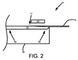
もちろん、冷却プレート14の長さにわたる種々の冷却温度、融液10の種々の流速やシート13の引っ張り速度、シート形成装置21の様々な部分の長さ、又は、シート形成装置21内のタイミングは、プロセス制御のために用いることができる。融液10がシリコンである場合、シート13は、シート形成装置21を用いることにより、多結晶の又は単結晶のシートとなり得る。図1は、シート13を融液10から形成することができるシート形成装置の一例に過ぎない。シート13を水平に成長させる他の装置又は方法も可能である。本明細書で説明する実施形態は、任意のシート13を水平に成長させる装置又は方法に適用することができる。従って、本明細書で説明する実施形態は、図1の特定の実施形態だけに限定されない。例えば、図2は、シートを融液から分離する装置の第2の実施形態の側断面図である。シート形成装置31において、融液10は容器16内に収容されている。シート13は、冷却プレート14による形成後に、融液10から引っ張り出される。図2では水平であるが、シート13は、融液10に対してある角度を成すこともできる。図1〜2の実施形態では、融液10は、例えばシート形成装置21又は31の側面の周りと云ったような、シート形成装置21又は31の周りを循環させることができる。もちろん、融液10は、シート13の形成プロセスの一部又は全ての期間中、静止させることもできる。
Of course, various cooling temperatures over the length of the cooling
液体が気体と接触すると、メニスカス界面が形成される。この界面はヤング−ラプラス方程式に従う。二次元において、その方程式は

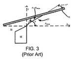
図3は、LASS用のメニスカス安定化の側断面図である。図3の座標系に関して、曲率半径は、メニスカスを描写する線の一次導関数及び二次導関数で表すことができる。図3におけるメニスカス27間の圧力差は、重力(ρgy)による融液10の液体中の静水圧に起因する。従って、ヤング−ラプラス方程式は、二階微分方程式になる。
ガスジェットは、融液10における局所的な圧力を高くすることにより、メニスカスを安定化させるのに、用いることができる。例えば、メニスカスのガス側の局所的圧力は高めることができる。本明細書で説明する実施形態を用いるメニスカスの安定化は、融液の流れに無関係として、融液10が流れ始める前に初期結晶化が生じるようにする。これは、融液の流れを用いるシステムでの種結晶の種付けを簡単にする。シートは、本明細書で説明する実施形態を用いて、水平方向に成長させることができ、これは、ある角度での引っ張り速度に対する、成長速度の複雑なバランスを排除(すなわち、熱除去)する。シートの成長は、融液からの分離を行う容器のエッジの上流で行うことができる。
The gas jet can be used to stabilize the meniscus by increasing the local pressure in the
図4は、ガス衝突を用いてメニスカスを安定化させる実施形態の側断面図である。本実施形態では、シート13を水平方向に引っ張る。容器16の壁は、融液10の表面レベルより下であり、この表面レベルは、本例では、x軸とy軸が交差する箇所、すなわち、シート13が位置するところである。融液10は、シート13の下にメニスカス27が形成されることによりこぼれない。例示していないが、融液10は、例えば、図1に例示のスピルウェイ12を用いるなどして、容器16のエッジを越えて、循環させることも、また、図6に例示するように、メニスカス27を形成することもあることは勿論である。図4へ戻るに、凹形のメニスカス27を維持するための圧力差は、メニスカス27の下のガスジェット22より提供され、ガスジェット22は、このガスジェット22から出る矢印により示されるように、メニスカス27又は容器16のエッジに向けて、ある角度に傾けている。このような例では、ヤング−ラプラス方程式は、
ガスジェット22の出口での圧力の大きさは、ガスの流れ及びガスを流すガスジェット22の開口部の幅に依存する。開口部は、例えば、スリットジェットとすることができる。これは、運動量の保存法則を用いて、少なくともある程度は推定することができる。従って、ガスがメニスカス27を跳ね返えさせるよどみ点における圧力は、
ここで推定される圧力は、ガスジェット22の出口における圧力に過ぎない。圧力は、軸方向及び横方向にも低下し得る。圧力分布は、楕円ガウス分布として近似させることができる。
図5は、ガスジェットからの圧力分布を例示する断面図である。これは、上記の式を解く。全ての場合に、ガスジェット22の出口でP0=40Pa、x0=6mm、ガスジェット22の出口でy0=−4mm、σx=4mm、σy=0.8mm及びΨ=45°である。σx及びσyは、ガスジェット22の周りの圧力の楕円分布を表す。メニスカス27が容器16に留まる場所は、メニスカス27の形状に影響を及ぼす。α=11°の場合、メニスカス27はシート13の1mm下でθ=17°で容器16の壁に留まる。α=11°の場合、メニスカス27はシート13の2mm下でθ=15.87°で容器16の壁に留まる。α=11°の場合、メニスカス27はシート13の2.5mm下でθ=10.58°で容器16の壁に留まる。α=0°の場合、メニスカス27はシート13の1mm下でθ=7.21°で容器16の壁に留まる。
FIG. 5 is a cross-sectional view illustrating the pressure distribution from the gas jet. This solves the above equation. In all cases, P 0 = 40 Pa, x 0 = 6 mm at the outlet of the
従って、ガス衝突を用いることにより、安定なメニスカス27を、約11°の接触角でシート13の少なくとも2.5mm下で容器16の壁に留めることができる。たとえ接触角が0°と低かったとしても、安定なメニスカス27が、まだ、シート13の1mm下で容器16の壁に維持される。ガスジェットの衝突は、粘性力により引き起こされる抗力を補償することもできる。ガスジェットの衝突の圧力は、メニスカス27を安定させること、すなわち、メニスカス27を容器16に留めることを維持するのに役立つように設定することができる。
Thus, by using gas collision, a
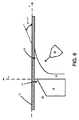
図6は、スピルウェイと共にガス衝突を用いるメニスカス安定化の実施形態の断面図である。融液10はスピルウェイ12を越えて流れる。メニスカス27は、スピルウェイ12を越えて通る融液10でできる。もちろん、他の実施形態も可能である。
FIG. 6 is a cross-sectional view of an embodiment of meniscus stabilization using gas collision with a spillway. The
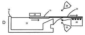
図7は、シートの形成を伴うガスジェットの第1の実施形態の側断面図である。このシステムは、支持テーブル23から離れたガスジェット22を有する。支持テーブル23は、シート13を支持するために、空気又は他の流体のジェットを用いることができるが、ローラー又は他の機構を用いることもできる。本特定の実施形態では、もっと多く又はもっと少なく設けることはできるけれども、2つのガスジェット22、25を用いる。シート13の下のガスジェット22は、メニスカス27を安定させ、その位置及び角度を調整することができる。シート13の上のガスジェット25は、ガスジェット22からの衝突力の垂直方向成分のバランスを取る。ガスジェット22及び25からの流れは、他の流れも可能であるけれども、一例では、ほぼ等しくすることができる。アルゴン、別の希ガス、別の不活性ガス又は当業者に既知の他の種を、ガスジェット22又は25に用いることができる。容器16は、融液10のメニスカス27を留めて、融液を滴らせないで接触角を大きく変えることができる機構、すなわち溝24を含むのがよい。そのような機構、すなわち溝24のない容器16の表面は、そこに留まるメニスカス27を有することができるも、滴りが生じる前のメニスカス27の角度は制限される。例えば、この角度は約87°である。上記機構、すなわち溝24を加えることにより、滴りが生じる前に、メニスカス27をたるませ、すなわち容器16の表面から約177°の角度を持つようにすることを可能にする。
FIG. 7 is a cross-sectional side view of a first embodiment of a gas jet with sheet formation. The system has a
図8は、シートの形成を伴うガスジェットの第2の実施形態の側断面図である。本実施形態では、ガスジェット22を支持テーブル23に組み込む。別の実施形態では、シート13の上方にガスジェットを設けて、図7に例示するように、垂直方向の衝突力のバランスを取るようにすることができる。
FIG. 8 is a cross-sectional side view of a second embodiment of a gas jet with sheet formation. In the present embodiment, the
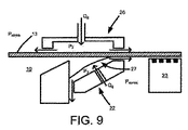
図9は、シートの形成を伴うガスジェットの第3の実施形態の側断面図である。ガスジェット22は、圧力セル26の一部である。圧力セル26内は、エッジ又はシールで導通が制限されることにより、高めの圧力(P2)である。圧力セル26内のガスは、矢印で示すように流れる。本例のP2は、大気圧(Patmos)より大きい。圧力セル26の上部は、底部の上の気体軸受の上に浮いている。底部のレベルは、融液10のレベルに一致するように設定することができる。圧力セル26とシート13との間のギャップ又はシールは、一例では、0.5mm未満の寸法とすることができる。メニスカス27は、圧力セル26の底部の一部であるガスジェット22のために、この圧力セル26内に少なくとも部分的に含まれる。
FIG. 9 is a side cross-sectional view of a third embodiment of a gas jet with sheet formation. The
図10A〜Dは、ガスジェットの安定化により可能にすることができる種付けを例示する。本明細書に開示した実施形態は、容器16内の流れに無関係にメニスカスを安定化させる。従って、結晶の開始は、融液10が、流れ始める前に始まり、シート形成プロセスを簡単にすることができる。図10Aでは、種ウエーハ28を挿入する。種ウエーハ28は、例えば、所望の結晶配向性を有する約0.7mmの厚さのエレクトロニクスグレードのシリコンウエーハとすることができる。種ウエーハ28のレベルは、この種ウエーハ28のレベルを融液10のレベルに対して制御する支持テーブル23の上に種ウエーハ28が載るように制御する。融液10は、例えば、この融液10のシリコンの表面張力を用いて、メサ29を作り、融液10は、容器16の壁のエッジの上に位置するようにすることができる。従って、種ウエーハ28が融液10に触れる前に、図10Aに例示するように、融液10には凸状のメニスカスができている。ガスジェット22、25は、種ウエーハ28が融液10に触れる前に、このメニスカスを安定させるのに用いることができる。もちろん、もっと多い又はもっと少ないガスジェットを用いることも可能である。
10A-D illustrate seeding that can be enabled by stabilization of the gas jet. The embodiments disclosed herein stabilize the meniscus independent of the flow in the
図10Bでは、種ウエーハ28は、矢印の方向に動いた後に、融液10に触れる。メニスカス27は、種ウエーハ28の下にできる。凸状となるこのメニスカス27は、容器16の壁と種ウエーハ28との間のギャップを埋める。凸状のメニスカス27は、種ウエーハ28の幅を越えて容器16の壁に付着したままとなる。メサ29のメニスカスと種ウエーハ28の下の凸状のメニスカス27との間のこの遷移個所のメニスカスは、不均一になり得る。この不均一性は、プロセスがほぼ等温の環境で生じるため、シート13の厚さの均一性又は品質に影響を及ぼすことはないと思われる。
In FIG. 10B, the
図10Cでは、種ウエーハ28を、矢印の方向に平行移動させる。この平行移動は、種ウエーハ28の一端でローラー又は他の機構により行うことができる。種ウエーハ28は、この種ウエーハ28が挿入されたのと反対方向に、冷却プレート14の下を動く。冷却プレート14は、最初は、ターン・オフさせるか、又は、融液10の温度に等しく、又は、融液10の温度より高くすることができる。冷却プレート14を、メニスカス27が付着する容器16の壁の上流の所定距離の所に配置すれば、メニスカス27の影響は最小になり得る。冷却プレート14をターン・オンさせると、種ウエーハ28の近くで凍結が始まる。種ウエーハ28を引っ張る動作が始まって、シート13は引っ張り出される。
In FIG. 10C, the
図10Dでは、融液10は、例えば、ポンプを用いて流れ始める。別の実施形態では、融液10はスピルウェイを越えることができる。シート13の幅は、融液10が流れ始めるにつれて、大きくすることができる。冷却プレート14の温度及び融液10の流れやシート13が動く速度は、シート13の所望の厚さを得るために、調整することができる。このようにして、定常状態プロセスを達成することができる。
In FIG. 10D, the
ガスジェットを用いるメニスカスの安定化には、多数の利点がある。それは、水平シートの形成又は水平リボンの成長(HGR)システムに適用することができ、一例では、LASSを回避するために用いることができる。一実施形態では、シート13を水平に引っ張ることができ、結晶形成領域はメニスカス27の上流に位置するようにすることができる。これは、シートを形成する間にシート13に悪影響を及ぼすことになる、引っ張りメカニズムにより生じる摂動を最小にする。融液10の流速は、シート13の速度に関係なく、制御することができる。これは、より単純な種付けプロセスを可能にする。さらに、融液10の流出を低減し又は防ぐことができる。
There are numerous advantages to stabilizing the meniscus using a gas jet. It can be applied to horizontal sheet formation or horizontal ribbon growth (HGR) systems, and in one example can be used to avoid LASS. In one embodiment, the
図11は、ガスジェットの実施形態の断面図である。ガスジェット22はプレナム32及び開口部30を有する。ガスは矢印の方向に流れる。プレナム32を開口部30より大きくすることにより、均一な圧力と開口部30の大きさにわたる均一な流れを確保することができる。一実施形態では、開口部30は、図4のシート13のようなシートの幅にほぼ等しい幅を有する。もちろん、他の大きさも可能である。
FIG. 11 is a cross-sectional view of an embodiment of a gas jet. The
本明細書で開示した実施形態では、ガスジェット22は、特定の温度で、ガスを向けることができる。メニスカスが凍結しないように、ガスは暖めることができる。シートが溶融されないように、ガスを冷却するか、さもなければ、シートを冷却することができる。
In the embodiments disclosed herein, the
本発明は、本明細書に記載した特定の実施形態による範囲に限定すべきではない。実際に、本明細書に記載した実施形態に加えて、本発明の他の様々な実施形態及び変更は、前述の記載及び添付図面から当業者には明らかであろう。従って、そのような他の実施形態及び変更は、本発明の範囲内に入ることを意図している。さらに、本発明は、特定の目的のため、特定の環境で、特定の実施のコンテキストで、本明細書に記載したけれども、当業者は、その有用性がそれらに限定されず、本発明が、任意の数の目的のため、任意の数の環境で、有用に実施することができることを理解するであろう。従って、以下に記載の特許請求の範囲は、本明細書に記載されているように、本発明の全容及び精神に鑑みて解釈すべきである。 The present invention should not be limited to the scope according to the specific embodiments described herein. Indeed, in addition to the embodiments set forth herein, various other embodiments and modifications of the invention will be apparent to those skilled in the art from the foregoing description and accompanying drawings. Accordingly, such other embodiments and modifications are intended to be within the scope of the present invention. Further, although the present invention has been described herein for a specific purpose, in a specific environment and in a specific implementation context, those skilled in the art will not be limited in their utility, It will be appreciated that the present invention can be usefully implemented in any number of environments for any number of purposes. Accordingly, the claims set forth below should be construed in view of the full breadth and spirit of the invention as set forth herein.
Claims (13)
材料のシートを、容器内に収容される該材料の融液の表面上に水平に平行移動させるステップと、
前記融液のメニスカスを圧力セル内に含むステップであって、前記メニスカスは前記容器のエッジと前記シートの下面との間に形成されるステップと、
前記圧力セル内に含まれる第1のガスジェットからのガスを前記メニスカスに向けるステップと、
前記シートを前記融液から取り出すステップと、
を含み、
前記圧力セル内の圧力は、大気圧より大きい、シート形成方法。 A sheet forming method comprising:
Horizontally translating a sheet of material onto the surface of the melt of material contained in the container;
Including a meniscus of the melt in a pressure cell, the meniscus being formed between an edge of the container and a lower surface of the sheet;
Directing gas from a first gas jet contained in the pressure cell to the meniscus;
Removing the sheet from the melt;
Including
The sheet forming method, wherein the pressure in the pressure cell is greater than atmospheric pressure.
容器内に収容される材料の融液に種結晶を付与するステップと、
前記融液のメニスカスを圧力セル内に含むステップであって、前記メニスカスは前記容器のエッジで前記種結晶及び前記融液に対して形成されるステップと、
前記圧力セル内に含まれる第1のガスジェットからのガスを前記メニスカスに向けるステップと、
前記融液の一部を凍結させて、前記融液の表面上に前記材料のシートを水平に形成するステップと、
前記シートを前記融液から取り出すステップと、
を含み、
前記圧力セル内の圧力は、大気圧より大きい、シート形成方法。 A sheet forming method comprising:
Providing a seed crystal to the melt of the material contained in the container;
Including the melt meniscus in a pressure cell, wherein the meniscus is formed against the seed crystal and the melt at an edge of the vessel;
Directing gas from a first gas jet contained in the pressure cell to the meniscus;
Freezing a portion of the melt to form a sheet of the material horizontally on the surface of the melt;
Removing the sheet from the melt;
Including
The sheet forming method, wherein the pressure in the pressure cell is greater than atmospheric pressure.
Applications Claiming Priority (5)
| Application Number | Priority Date | Filing Date | Title |
|---|---|---|---|
| US33207310P | 2010-05-06 | 2010-05-06 | |
| US61/332,073 | 2010-05-06 | ||
| US13/037,789 | 2011-03-01 | ||
| US13/037,789 US8685162B2 (en) | 2010-05-06 | 2011-03-01 | Removing a sheet from the surface of a melt using gas jets |
| PCT/US2011/026790 WO2011139402A1 (en) | 2010-05-06 | 2011-03-02 | Removing a sheet from the surface of a melt using gas jets |
Related Child Applications (1)
| Application Number | Title | Priority Date | Filing Date |
|---|---|---|---|
| JP2015084457A Division JP5961303B2 (en) | 2010-05-06 | 2015-04-16 | Removal of sheet from melt surface using gas jet |
Publications (3)
| Publication Number | Publication Date |
|---|---|
| JP2013530911A JP2013530911A (en) | 2013-08-01 |
| JP2013530911A5 JP2013530911A5 (en) | 2014-03-13 |
| JP5771271B2 true JP5771271B2 (en) | 2015-08-26 |
Family
ID=44901074
Family Applications (2)
| Application Number | Title | Priority Date | Filing Date |
|---|---|---|---|
| JP2013509053A Active JP5771271B2 (en) | 2010-05-06 | 2011-03-02 | Removal of sheet from melt surface using gas jet |
| JP2015084457A Active JP5961303B2 (en) | 2010-05-06 | 2015-04-16 | Removal of sheet from melt surface using gas jet |
Family Applications After (1)
| Application Number | Title | Priority Date | Filing Date |
|---|---|---|---|
| JP2015084457A Active JP5961303B2 (en) | 2010-05-06 | 2015-04-16 | Removal of sheet from melt surface using gas jet |
Country Status (7)
| Country | Link |
|---|---|
| US (2) | US8685162B2 (en) |
| EP (2) | EP2567003B1 (en) |
| JP (2) | JP5771271B2 (en) |
| KR (2) | KR101898905B1 (en) |
| CN (1) | CN103025926B (en) |
| TW (1) | TWI550142B (en) |
| WO (1) | WO2011139402A1 (en) |
Families Citing this family (6)
| Publication number | Priority date | Publication date | Assignee | Title |
|---|---|---|---|---|
| US9957636B2 (en) * | 2014-03-27 | 2018-05-01 | Varian Semiconductor Equipment Associates, Inc. | System and method for crystalline sheet growth using a cold block and gas jet |
| US10526720B2 (en) * | 2015-08-19 | 2020-01-07 | Varian Semiconductor Equipment Associates, Inc. | Apparatus for forming crystalline sheet from a melt |
| US10179958B2 (en) * | 2016-09-16 | 2019-01-15 | Varian Semiconductor Equipment Associates, Inc | Apparatus and method for crystalline sheet growth |
| WO2020033419A1 (en) * | 2018-08-06 | 2020-02-13 | Carnegie Mellon University | Method for producing a sheet from a melt by imposing a periodic change in the rate of pull |
| WO2020231971A1 (en) * | 2019-05-13 | 2020-11-19 | Leading Edge Crystal Technologies, Inc. | Exposure of a silicon ribbon to gas in a furnace |
| MX2022001458A (en) | 2019-08-09 | 2022-06-08 | Leading Edge Equipment Tech Inc | Producing a ribbon or wafer with regions of low oxygen concentration. |
Family Cites Families (15)
| Publication number | Priority date | Publication date | Assignee | Title |
|---|---|---|---|---|
| JPS5215485A (en) * | 1975-07-28 | 1977-02-05 | Toyo Silicon Kk | Process for growth of ribbon crystals by lateral pulling |
| DE2633961C2 (en) * | 1975-07-28 | 1986-01-02 | Mitsubishi Kinzoku K.K. | Method of pulling a thin ribbon of single crystal semiconductor |
| JPS5261180A (en) | 1975-11-14 | 1977-05-20 | Toyo Shirikon Kk | Horizontal growth of crystal ribbons |
| US4221754A (en) * | 1977-12-29 | 1980-09-09 | Nowak Welville B | Method for producing solid ribbons |
| US4289571A (en) | 1979-06-25 | 1981-09-15 | Energy Materials Corporation | Method and apparatus for producing crystalline ribbons |
| US4627887A (en) * | 1980-12-11 | 1986-12-09 | Sachs Emanuel M | Melt dumping in string stabilized ribbon growth |
| US6019576A (en) * | 1997-09-22 | 2000-02-01 | Thut; Bruno H. | Pumps for pumping molten metal with a stirring action |
| JP2001122696A (en) | 1999-10-21 | 2001-05-08 | Matsushita Seiko Co Ltd | Method of producing ribbon silicon wafer |
| JP2002114597A (en) * | 2000-10-06 | 2002-04-16 | Sharp Corp | Method for manufacturing crystal sheet and solar cell which uses the crystal sheet |
| CN101522960B (en) | 2006-09-28 | 2012-07-25 | Amg艾迪卡斯特太阳能公司 | Method and apparatus for the production of crystalline silicon substrates |
| US7855087B2 (en) | 2008-03-14 | 2010-12-21 | Varian Semiconductor Equipment Associates, Inc. | Floating sheet production apparatus and method |
| US7816153B2 (en) | 2008-06-05 | 2010-10-19 | Varian Semiconductor Equipment Associates, Inc. | Method and apparatus for producing a dislocation-free crystalline sheet |
| US8475591B2 (en) | 2008-08-15 | 2013-07-02 | Varian Semiconductor Equipment Associates, Inc. | Method of controlling a thickness of a sheet formed from a melt |
| ES2425885T3 (en) * | 2008-08-18 | 2013-10-17 | Max Era, Inc. | Procedure and apparatus for the development of a crystalline tape while controlling the transport of contaminants in suspension in a gas through a tape surface |
| CA2754880C (en) | 2009-03-09 | 2018-07-03 | 1366 Technologies Inc. | Methods and apparati for making thin semiconductor bodies from molten material |
-
2011
- 2011-03-01 US US13/037,789 patent/US8685162B2/en active Active
- 2011-03-02 CN CN201180031762.2A patent/CN103025926B/en not_active Expired - Fee Related
- 2011-03-02 KR KR1020177026816A patent/KR101898905B1/en active IP Right Grant
- 2011-03-02 WO PCT/US2011/026790 patent/WO2011139402A1/en active Application Filing
- 2011-03-02 EP EP11710924.9A patent/EP2567003B1/en not_active Not-in-force
- 2011-03-02 KR KR1020127030651A patent/KR101783226B1/en active IP Right Grant
- 2011-03-02 JP JP2013509053A patent/JP5771271B2/en active Active
- 2011-03-02 EP EP17201509.1A patent/EP3305946B1/en active Active
- 2011-03-03 TW TW100107128A patent/TWI550142B/en active
-
2014
- 2014-04-01 US US14/242,566 patent/US9677193B2/en active Active
-
2015
- 2015-04-16 JP JP2015084457A patent/JP5961303B2/en active Active
Also Published As
| Publication number | Publication date |
|---|---|
| EP3305946A1 (en) | 2018-04-11 |
| WO2011139402A8 (en) | 2013-01-31 |
| JP2013530911A (en) | 2013-08-01 |
| KR101898905B1 (en) | 2018-09-14 |
| EP3305946B1 (en) | 2019-05-01 |
| CN103025926A (en) | 2013-04-03 |
| US20110271899A1 (en) | 2011-11-10 |
| JP5961303B2 (en) | 2016-08-02 |
| CN103025926B (en) | 2016-03-30 |
| TW201139761A (en) | 2011-11-16 |
| EP2567003A1 (en) | 2013-03-13 |
| WO2011139402A1 (en) | 2011-11-10 |
| US20140209016A1 (en) | 2014-07-31 |
| EP2567003B1 (en) | 2018-01-10 |
| US9677193B2 (en) | 2017-06-13 |
| KR101783226B1 (en) | 2017-09-29 |
| US8685162B2 (en) | 2014-04-01 |
| TWI550142B (en) | 2016-09-21 |
| KR20170113694A (en) | 2017-10-12 |
| KR20130100058A (en) | 2013-09-09 |
| JP2015157757A (en) | 2015-09-03 |
Similar Documents
| Publication | Publication Date | Title |
|---|---|---|
| JP5961303B2 (en) | Removal of sheet from melt surface using gas jet | |
| US8475591B2 (en) | Method of controlling a thickness of a sheet formed from a melt | |
| US7816153B2 (en) | Method and apparatus for producing a dislocation-free crystalline sheet | |
| US8226903B2 (en) | Removal of a sheet from a production apparatus | |
| JP5771272B2 (en) | Gas lift pump for flowing and purifying molten silicon | |
| JP5848752B2 (en) | Removal of sheet from melt surface using elasticity and buoyancy | |
| US20100080905A1 (en) | Solute stabilization of sheets formed from a melt |
Legal Events
| Date | Code | Title | Description |
|---|---|---|---|
| A521 | Request for written amendment filed |
Free format text: JAPANESE INTERMEDIATE CODE: A523 Effective date: 20140124 |
|
| A621 | Written request for application examination |
Free format text: JAPANESE INTERMEDIATE CODE: A621 Effective date: 20140124 |
|
| A977 | Report on retrieval |
Free format text: JAPANESE INTERMEDIATE CODE: A971007 Effective date: 20140529 |
|
| A131 | Notification of reasons for refusal |
Free format text: JAPANESE INTERMEDIATE CODE: A131 Effective date: 20140617 |
|
| A601 | Written request for extension of time |
Free format text: JAPANESE INTERMEDIATE CODE: A601 Effective date: 20140912 |
|
| A602 | Written permission of extension of time |
Free format text: JAPANESE INTERMEDIATE CODE: A602 Effective date: 20140922 |
|
| A521 | Request for written amendment filed |
Free format text: JAPANESE INTERMEDIATE CODE: A523 Effective date: 20141016 |
|
| A02 | Decision of refusal |
Free format text: JAPANESE INTERMEDIATE CODE: A02 Effective date: 20150113 |
|
| A521 | Request for written amendment filed |
Free format text: JAPANESE INTERMEDIATE CODE: A523 Effective date: 20150416 |
|
| A911 | Transfer to examiner for re-examination before appeal (zenchi) |
Free format text: JAPANESE INTERMEDIATE CODE: A911 Effective date: 20150422 |
|
| TRDD | Decision of grant or rejection written | ||
| A01 | Written decision to grant a patent or to grant a registration (utility model) |
Free format text: JAPANESE INTERMEDIATE CODE: A01 Effective date: 20150609 |
|
| A61 | First payment of annual fees (during grant procedure) |
Free format text: JAPANESE INTERMEDIATE CODE: A61 Effective date: 20150626 |
|
| R150 | Certificate of patent or registration of utility model |
Ref document number: 5771271 Country of ref document: JP Free format text: JAPANESE INTERMEDIATE CODE: R150 |
|
| R250 | Receipt of annual fees |
Free format text: JAPANESE INTERMEDIATE CODE: R250 |
|
| R250 | Receipt of annual fees |
Free format text: JAPANESE INTERMEDIATE CODE: R250 |
|
| R250 | Receipt of annual fees |
Free format text: JAPANESE INTERMEDIATE CODE: R250 |
|
| R250 | Receipt of annual fees |
Free format text: JAPANESE INTERMEDIATE CODE: R250 |
|
| R250 | Receipt of annual fees |
Free format text: JAPANESE INTERMEDIATE CODE: R250 |
|
| R250 | Receipt of annual fees |
Free format text: JAPANESE INTERMEDIATE CODE: R250 |