JP5771032B2 - Honeycomb structure - Google Patents
Honeycomb structure Download PDFInfo
- Publication number
- JP5771032B2 JP5771032B2 JP2011059705A JP2011059705A JP5771032B2 JP 5771032 B2 JP5771032 B2 JP 5771032B2 JP 2011059705 A JP2011059705 A JP 2011059705A JP 2011059705 A JP2011059705 A JP 2011059705A JP 5771032 B2 JP5771032 B2 JP 5771032B2
- Authority
- JP
- Japan
- Prior art keywords
- fired body
- honeycomb fired
- cell
- honeycomb
- cross
- Prior art date
- Legal status (The legal status is an assumption and is not a legal conclusion. Google has not performed a legal analysis and makes no representation as to the accuracy of the status listed.)
- Active
Links
- 210000004027 cell Anatomy 0.000 claims description 485
- 230000002093 peripheral effect Effects 0.000 claims description 213
- 239000000919 ceramic Substances 0.000 claims description 119
- 239000012790 adhesive layer Substances 0.000 claims description 44
- 210000002421 cell wall Anatomy 0.000 claims description 44
- 239000010410 layer Substances 0.000 claims description 20
- 230000015572 biosynthetic process Effects 0.000 claims description 16
- 238000004519 manufacturing process Methods 0.000 description 31
- 239000000853 adhesive Substances 0.000 description 23
- 230000001070 adhesive effect Effects 0.000 description 23
- 238000000034 method Methods 0.000 description 23
- 239000007789 gas Substances 0.000 description 20
- 239000000463 material Substances 0.000 description 18
- 239000000203 mixture Substances 0.000 description 18
- 239000003566 sealing material Substances 0.000 description 18
- HBMJWWWQQXIZIP-UHFFFAOYSA-N silicon carbide Chemical compound [Si+]#[C-] HBMJWWWQQXIZIP-UHFFFAOYSA-N 0.000 description 17
- 229910010271 silicon carbide Inorganic materials 0.000 description 13
- 239000011248 coating agent Substances 0.000 description 12
- 238000000576 coating method Methods 0.000 description 12
- 239000002245 particle Substances 0.000 description 12
- 230000007547 defect Effects 0.000 description 11
- 238000011049 filling Methods 0.000 description 11
- 230000000694 effects Effects 0.000 description 9
- 238000007789 sealing Methods 0.000 description 9
- 239000011230 binding agent Substances 0.000 description 8
- 238000001125 extrusion Methods 0.000 description 8
- 238000010304 firing Methods 0.000 description 7
- 239000011148 porous material Substances 0.000 description 7
- -1 For example Substances 0.000 description 6
- PNEYBMLMFCGWSK-UHFFFAOYSA-N aluminium oxide Inorganic materials [O-2].[O-2].[O-2].[Al+3].[Al+3] PNEYBMLMFCGWSK-UHFFFAOYSA-N 0.000 description 6
- 239000000843 powder Substances 0.000 description 6
- 238000000746 purification Methods 0.000 description 6
- PEDCQBHIVMGVHV-UHFFFAOYSA-N Glycerine Chemical compound OCC(O)CO PEDCQBHIVMGVHV-UHFFFAOYSA-N 0.000 description 5
- 239000003054 catalyst Substances 0.000 description 5
- 239000012784 inorganic fiber Substances 0.000 description 5
- 239000000314 lubricant Substances 0.000 description 5
- XLYOFNOQVPJJNP-UHFFFAOYSA-N water Substances O XLYOFNOQVPJJNP-UHFFFAOYSA-N 0.000 description 5
- XUIMIQQOPSSXEZ-UHFFFAOYSA-N Silicon Chemical compound [Si] XUIMIQQOPSSXEZ-UHFFFAOYSA-N 0.000 description 4
- 239000011247 coating layer Substances 0.000 description 4
- 238000005238 degreasing Methods 0.000 description 4
- 239000002994 raw material Substances 0.000 description 4
- 229910052710 silicon Inorganic materials 0.000 description 4
- 239000010703 silicon Substances 0.000 description 4
- UHOVQNZJYSORNB-UHFFFAOYSA-N Benzene Chemical compound C1=CC=CC=C1 UHOVQNZJYSORNB-UHFFFAOYSA-N 0.000 description 3
- LYCAIKOWRPUZTN-UHFFFAOYSA-N Ethylene glycol Chemical compound OCCO LYCAIKOWRPUZTN-UHFFFAOYSA-N 0.000 description 3
- OKKJLVBELUTLKV-UHFFFAOYSA-N Methanol Chemical compound OC OKKJLVBELUTLKV-UHFFFAOYSA-N 0.000 description 3
- 238000005336 cracking Methods 0.000 description 3
- 238000001035 drying Methods 0.000 description 3
- 239000010954 inorganic particle Substances 0.000 description 3
- 239000007788 liquid Substances 0.000 description 3
- 229920000609 methyl cellulose Polymers 0.000 description 3
- 239000001923 methylcellulose Substances 0.000 description 3
- 235000010981 methylcellulose Nutrition 0.000 description 3
- 238000002156 mixing Methods 0.000 description 3
- 238000000465 moulding Methods 0.000 description 3
- 239000004014 plasticizer Substances 0.000 description 3
- RMAQACBXLXPBSY-UHFFFAOYSA-N silicic acid Chemical compound O[Si](O)(O)O RMAQACBXLXPBSY-UHFFFAOYSA-N 0.000 description 3
- 229910052582 BN Inorganic materials 0.000 description 2
- PZNSFCLAULLKQX-UHFFFAOYSA-N Boron nitride Chemical compound N#B PZNSFCLAULLKQX-UHFFFAOYSA-N 0.000 description 2
- 229920002134 Carboxymethyl cellulose Polymers 0.000 description 2
- KDLHZDBZIXYQEI-UHFFFAOYSA-N Palladium Chemical compound [Pd] KDLHZDBZIXYQEI-UHFFFAOYSA-N 0.000 description 2
- 229910052581 Si3N4 Inorganic materials 0.000 description 2
- VYPSYNLAJGMNEJ-UHFFFAOYSA-N Silicium dioxide Chemical compound O=[Si]=O VYPSYNLAJGMNEJ-UHFFFAOYSA-N 0.000 description 2
- 150000005215 alkyl ethers Chemical class 0.000 description 2
- 239000001768 carboxy methyl cellulose Substances 0.000 description 2
- 235000010948 carboxy methyl cellulose Nutrition 0.000 description 2
- 239000008112 carboxymethyl-cellulose Substances 0.000 description 2
- 230000002950 deficient Effects 0.000 description 2
- 235000014113 dietary fatty acids Nutrition 0.000 description 2
- KZHJGOXRZJKJNY-UHFFFAOYSA-N dioxosilane;oxo(oxoalumanyloxy)alumane Chemical compound O=[Si]=O.O=[Si]=O.O=[Al]O[Al]=O.O=[Al]O[Al]=O.O=[Al]O[Al]=O KZHJGOXRZJKJNY-UHFFFAOYSA-N 0.000 description 2
- 239000002612 dispersion medium Substances 0.000 description 2
- 239000000194 fatty acid Substances 0.000 description 2
- 229930195729 fatty acid Natural products 0.000 description 2
- 150000004665 fatty acids Chemical class 0.000 description 2
- 239000000835 fiber Substances 0.000 description 2
- 238000001914 filtration Methods 0.000 description 2
- 235000011187 glycerol Nutrition 0.000 description 2
- 229910052863 mullite Inorganic materials 0.000 description 2
- 150000004767 nitrides Chemical class 0.000 description 2
- BASFCYQUMIYNBI-UHFFFAOYSA-N platinum Chemical compound [Pt] BASFCYQUMIYNBI-UHFFFAOYSA-N 0.000 description 2
- 229910021426 porous silicon Inorganic materials 0.000 description 2
- HQVNEWCFYHHQES-UHFFFAOYSA-N silicon nitride Chemical compound N12[Si]34N5[Si]62N3[Si]51N64 HQVNEWCFYHHQES-UHFFFAOYSA-N 0.000 description 2
- 239000004925 Acrylic resin Substances 0.000 description 1
- 229920000178 Acrylic resin Polymers 0.000 description 1
- 229910000505 Al2TiO5 Inorganic materials 0.000 description 1
- OKTJSMMVPCPJKN-UHFFFAOYSA-N Carbon Chemical compound [C] OKTJSMMVPCPJKN-UHFFFAOYSA-N 0.000 description 1
- 239000004375 Dextrin Substances 0.000 description 1
- 229920001353 Dextrin Polymers 0.000 description 1
- LFQSCWFLJHTTHZ-UHFFFAOYSA-N Ethanol Chemical compound CCO LFQSCWFLJHTTHZ-UHFFFAOYSA-N 0.000 description 1
- 229920000663 Hydroxyethyl cellulose Polymers 0.000 description 1
- 239000004354 Hydroxyethyl cellulose Substances 0.000 description 1
- DGAQECJNVWCQMB-PUAWFVPOSA-M Ilexoside XXIX Chemical compound C[C@@H]1CC[C@@]2(CC[C@@]3(C(=CC[C@H]4[C@]3(CC[C@@H]5[C@@]4(CC[C@@H](C5(C)C)OS(=O)(=O)[O-])C)C)[C@@H]2[C@]1(C)O)C)C(=O)O[C@H]6[C@@H]([C@H]([C@@H]([C@H](O6)CO)O)O)O.[Na+] DGAQECJNVWCQMB-PUAWFVPOSA-M 0.000 description 1
- 229920003171 Poly (ethylene oxide) Polymers 0.000 description 1
- 239000002202 Polyethylene glycol Substances 0.000 description 1
- ZLMJMSJWJFRBEC-UHFFFAOYSA-N Potassium Chemical compound [K] ZLMJMSJWJFRBEC-UHFFFAOYSA-N 0.000 description 1
- NRTOMJZYCJJWKI-UHFFFAOYSA-N Titanium nitride Chemical compound [Ti]#N NRTOMJZYCJJWKI-UHFFFAOYSA-N 0.000 description 1
- 229910026551 ZrC Inorganic materials 0.000 description 1
- OTCHGXYCWNXDOA-UHFFFAOYSA-N [C].[Zr] Chemical compound [C].[Zr] OTCHGXYCWNXDOA-UHFFFAOYSA-N 0.000 description 1
- NIXOWILDQLNWCW-UHFFFAOYSA-N acrylic acid group Chemical group C(C=C)(=O)O NIXOWILDQLNWCW-UHFFFAOYSA-N 0.000 description 1
- 229910052783 alkali metal Inorganic materials 0.000 description 1
- 150000001340 alkali metals Chemical class 0.000 description 1
- 229910052784 alkaline earth metal Inorganic materials 0.000 description 1
- 150000001342 alkaline earth metals Chemical class 0.000 description 1
- 239000012300 argon atmosphere Substances 0.000 description 1
- 229910052788 barium Inorganic materials 0.000 description 1
- DSAJWYNOEDNPEQ-UHFFFAOYSA-N barium atom Chemical compound [Ba] DSAJWYNOEDNPEQ-UHFFFAOYSA-N 0.000 description 1
- 239000003795 chemical substances by application Substances 0.000 description 1
- 238000002485 combustion reaction Methods 0.000 description 1
- 150000001875 compounds Chemical class 0.000 description 1
- 238000010276 construction Methods 0.000 description 1
- PMHQVHHXPFUNSP-UHFFFAOYSA-M copper(1+);methylsulfanylmethane;bromide Chemical compound Br[Cu].CSC PMHQVHHXPFUNSP-UHFFFAOYSA-M 0.000 description 1
- 229910052878 cordierite Inorganic materials 0.000 description 1
- 238000005520 cutting process Methods 0.000 description 1
- 235000019425 dextrin Nutrition 0.000 description 1
- JSKIRARMQDRGJZ-UHFFFAOYSA-N dimagnesium dioxido-bis[(1-oxido-3-oxo-2,4,6,8,9-pentaoxa-1,3-disila-5,7-dialuminabicyclo[3.3.1]nonan-7-yl)oxy]silane Chemical compound [Mg++].[Mg++].[O-][Si]([O-])(O[Al]1O[Al]2O[Si](=O)O[Si]([O-])(O1)O2)O[Al]1O[Al]2O[Si](=O)O[Si]([O-])(O1)O2 JSKIRARMQDRGJZ-UHFFFAOYSA-N 0.000 description 1
- 239000010881 fly ash Substances 0.000 description 1
- 239000011521 glass Substances 0.000 description 1
- 239000010439 graphite Substances 0.000 description 1
- 229910002804 graphite Inorganic materials 0.000 description 1
- 235000019447 hydroxyethyl cellulose Nutrition 0.000 description 1
- 238000010030 laminating Methods 0.000 description 1
- QSHDDOUJBYECFT-UHFFFAOYSA-N mercury Chemical compound [Hg] QSHDDOUJBYECFT-UHFFFAOYSA-N 0.000 description 1
- 229910052753 mercury Inorganic materials 0.000 description 1
- NFFIWVVINABMKP-UHFFFAOYSA-N methylidynetantalum Chemical compound [Ta]#C NFFIWVVINABMKP-UHFFFAOYSA-N 0.000 description 1
- 229910000510 noble metal Inorganic materials 0.000 description 1
- 239000003960 organic solvent Substances 0.000 description 1
- 229910052574 oxide ceramic Inorganic materials 0.000 description 1
- 239000011224 oxide ceramic Substances 0.000 description 1
- 229910052763 palladium Inorganic materials 0.000 description 1
- 229910052697 platinum Inorganic materials 0.000 description 1
- 229920001223 polyethylene glycol Polymers 0.000 description 1
- 229920001451 polypropylene glycol Polymers 0.000 description 1
- 229910052700 potassium Inorganic materials 0.000 description 1
- 239000011591 potassium Substances 0.000 description 1
- AABBHSMFGKYLKE-SNAWJCMRSA-N propan-2-yl (e)-but-2-enoate Chemical compound C\C=C\C(=O)OC(C)C AABBHSMFGKYLKE-SNAWJCMRSA-N 0.000 description 1
- 230000008929 regeneration Effects 0.000 description 1
- 238000011069 regeneration method Methods 0.000 description 1
- 229910052703 rhodium Inorganic materials 0.000 description 1
- 239000010948 rhodium Substances 0.000 description 1
- MHOVAHRLVXNVSD-UHFFFAOYSA-N rhodium atom Chemical compound [Rh] MHOVAHRLVXNVSD-UHFFFAOYSA-N 0.000 description 1
- 239000000377 silicon dioxide Substances 0.000 description 1
- 239000000344 soap Substances 0.000 description 1
- 229910052708 sodium Inorganic materials 0.000 description 1
- 239000011734 sodium Substances 0.000 description 1
- 239000007787 solid Substances 0.000 description 1
- 239000004071 soot Substances 0.000 description 1
- 239000000126 substance Substances 0.000 description 1
- 239000000758 substrate Substances 0.000 description 1
- 150000005846 sugar alcohols Polymers 0.000 description 1
- 229910003468 tantalcarbide Inorganic materials 0.000 description 1
- MTPVUVINMAGMJL-UHFFFAOYSA-N trimethyl(1,1,2,2,2-pentafluoroethyl)silane Chemical compound C[Si](C)(C)C(F)(F)C(F)(F)F MTPVUVINMAGMJL-UHFFFAOYSA-N 0.000 description 1
- UONOETXJSWQNOL-UHFFFAOYSA-N tungsten carbide Chemical compound [W+]#[C-] UONOETXJSWQNOL-UHFFFAOYSA-N 0.000 description 1
Images


Description
本発明は、ハニカム構造体に関する。 The present invention relates to a honeycomb structure.
バス、トラック等の車両及び建設機械等の内燃機関から排出される排ガス中に含有されるスス等のパティキュレート(以下、PMともいう)及びその他の有害成分が環境及び人体に害を及ぼすことが最近問題となっている。そこで、排ガス中のPMを捕集して排ガスを浄化するハニカムフィルタとして、多孔質セラミックからなるハニカム構造体が種々提案されている。 Particulates such as soot (hereinafter also referred to as PM) and other harmful components contained in exhaust gas discharged from internal combustion engines such as buses and trucks and construction machinery may cause harm to the environment and the human body. It has become a problem recently. Accordingly, various honeycomb structures made of porous ceramics have been proposed as honeycomb filters for collecting PM in exhaust gas and purifying the exhaust gas.
このようなハニカム構造体として、従来、多数のセルを有するハニカム焼成体が複数個結束されたセラミックブロックからなるハニカム構造体が知られている。
特許文献1には、異なる形状を有するハニカム焼成体が複数個結束されたセラミックブロックからなるハニカム構造体が開示されている。
Conventionally known as such a honeycomb structure is a honeycomb structure made of ceramic blocks in which a plurality of honeycomb fired bodies having a large number of cells are bundled.
Patent Document 1 discloses a honeycomb structure including ceramic blocks in which a plurality of honeycomb fired bodies having different shapes are bundled.
図18(a)及び図18(b)は、異なる形状を有するハニカム焼成体が複数個結束されたセラミックブロックからなる従来のハニカム構造体を構成するハニカム焼成体のうち、ハニカム構造体の最外周に位置するハニカム焼成体の一例を模式的に示す斜視図である。
図18(a)及び図18(b)に示すハニカム焼成体1110、1120では、多数のセル1111、1112、1121、1122がその長手方向に並設されて設けられており、セル1111、1121はセル壁1113、1123で隔てられている。また、セル1111、1121は、その周囲を外周壁1115、1125で囲まれている。
18 (a) and 18 (b) show the outermost periphery of the honeycomb structure among the honeycomb fired bodies constituting the conventional honeycomb structure formed of ceramic blocks in which a plurality of honeycomb fired bodies having different shapes are bundled. FIG. 2 is a perspective view schematically showing an example of a honeycomb fired body positioned in a position.
In the honeycomb fired
多数のセル1111、1112、1121、1122のうち、セラミックブロックの外周面を構成する外周壁1114、1124に最も近いセル1112、1122のその長手方向に垂直な断面形状(以下、単に断面形状ともいう)は、それらのセルより内側に位置するセルの断面形状と異なっている。すなわち、セル1112、1122の断面形状は、略三角形又は略台形となっており、セル1112、1122の一辺が、上記外周壁1114、1124に沿って形成されている。
また、セラミックブロックの外周面を構成する外周壁1114、1124は、曲面により構成されている。
Among a large number of
Moreover, the outer
異なる形状を有するハニカム焼成体が複数個結束されたセラミックブロックからなるハニカム構造体は、下記のような方法により製造することができる。
まず、セラミック粉末や水等を混合して成形体製造用の湿潤混合物を調製する。
次に、この湿潤混合物を押出成形して、異なる形状を有するハニカム成形体を作製する。
続いて、得られたハニカム成形体を乾燥機を用いて乾燥する。
乾燥後、ハニカム成形体を焼成することにより、ハニカム焼成体を作製する。
次に、接着材ペーストを介して複数個のハニカム焼成体の側面同士を接着させてハニカム焼成体の集合体を作製し、上記接着材ペーストを乾燥固化させて接着材層を形成することにより、セラミックブロックを作製する。その後、必要に応じて、セラミックブロックの外周にコート層を形成することによりハニカム構造体を製造する。
A honeycomb structure made of ceramic blocks in which a plurality of honeycomb fired bodies having different shapes are bundled can be manufactured by the following method.
First, a wet mixture for forming a molded body is prepared by mixing ceramic powder and water.
Next, this wet mixture is extruded to produce honeycomb formed bodies having different shapes.
Subsequently, the obtained honeycomb formed body is dried using a dryer.
After drying, the honeycomb formed body is fired to produce a honeycomb fired body.
Next, side surfaces of a plurality of honeycomb fired bodies are bonded to each other through an adhesive paste to produce an aggregate of honeycomb fired bodies, and the adhesive paste is dried and solidified to form an adhesive layer. Make a ceramic block. Thereafter, if necessary, a honeycomb structure is manufactured by forming a coat layer on the outer periphery of the ceramic block.
セラミックブロックを作製するために複数個のハニカム焼成体を結束させる際には、それぞれのハニカム焼成体について、機械や治具を用いてハニカム焼成体の側面を把持する必要がある。
特許文献1に記載された従来のハニカム構造体では、ハニカム焼成体の外周壁のうち、セラミックブロックの外周を構成する外周壁が、曲面により構成されている。
そのため、ハニカム構造体の最外周に位置するハニカム焼成体、特に、図18(a)に示すような曲面形状を有する従来のハニカム焼成体では、把持しにくいという問題がある。また、このような曲面形状を有するハニカム焼成体を無理に把持しようとすると、ハニカム焼成体を把持した部分において欠けやクラック等が発生しやすいという問題がある。これにより、ハニカム構造体の製造効率の低下を招く。
When a plurality of honeycomb fired bodies are bundled to produce a ceramic block, it is necessary to grip the side surfaces of the honeycomb fired bodies using a machine or a jig for each honeycomb fired body.
In the conventional honeycomb structure described in Patent Document 1, the outer peripheral wall constituting the outer periphery of the ceramic block among the outer peripheral walls of the honeycomb fired body is formed of a curved surface.
Therefore, the honeycomb fired body located on the outermost periphery of the honeycomb structure, particularly the conventional honeycomb fired body having a curved shape as shown in FIG. In addition, when the honeycomb fired body having such a curved shape is forcibly gripped, there is a problem in that chipping, cracking, and the like are likely to occur in the portion where the honeycomb fired body is gripped. Thereby, the manufacturing efficiency of the honeycomb structure is reduced.
本発明は、上記の問題を解決するためになされたものであり、ハニカム焼成体を把持しやすく、かつ、欠け及びクラック等の不良が発生しにくい、製造効率の良いハニカム構造体を提供することを目的とする。 The present invention has been made to solve the above-described problems, and provides a honeycomb structure with high manufacturing efficiency that is easy to grip a honeycomb fired body and is less likely to cause defects such as chipping and cracking. With the goal.
上記目的を達成するために、請求項1に記載のハニカム構造体は、多数のセルがセル壁を隔てて長手方向に並設され、周囲に外周壁が形成されたハニカム焼成体が、接着材層を介して複数個結束されたセラミックブロックからなるハニカム構造体であって、
上記セラミックブロックの上記ハニカム焼成体は、異なる形状を有し、
上記ハニカム焼成体は、上記セラミックブロックの外周部に位置する外方ハニカム焼成体と、上記外方ハニカム焼成体より内側に位置する内方ハニカム焼成体とからなり、
少なくとも1つの上記外方ハニカム焼成体において、上記外方ハニカム焼成体の外周のうち、上記セラミックブロックの外周を構成する外周の上記長手方向に垂直な断面は、曲線部と直線部とを少なくとも含み、
上記外方ハニカム焼成体の直線部は、上記外方ハニカム焼成体及び隣り合う内方ハニカム焼成体の間の接着材層、並びに、上記外方ハニカム焼成体及び隣り合う外方ハニカム焼成体の間の接着材層の少なくとも一方に平行であり、
上記外方ハニカム焼成体の直線部の長さは、5〜20mmであることを特徴とする。
In order to achieve the above object, the honeycomb structure according to claim 1, wherein the honeycomb fired body in which a large number of cells are arranged in parallel in the longitudinal direction across the cell wall, and an outer peripheral wall is formed around the cell, A honeycomb structure composed of a plurality of ceramic blocks bound through layers,
The honeycomb fired body of the ceramic block has a different shape,
The honeycomb fired body is composed of an outer honeycomb fired body positioned on the outer peripheral portion of the ceramic block, and an inner honeycomb fired body positioned inside the outer honeycomb fired body,
In at least one of the outer honeycomb fired bodies, a cross section perpendicular to the longitudinal direction of the outer periphery constituting the outer periphery of the ceramic block in the outer periphery of the outer honeycomb fired body includes at least a curved portion and a straight portion. ,
The straight portion of the outer honeycomb fired body includes an adhesive layer between the outer honeycomb fired body and the adjacent inner honeycomb fired body, and between the outer honeycomb fired body and the adjacent outer honeycomb fired body. Parallel to at least one of the adhesive layers of
The length of the straight portion of the outer honeycomb fired body is 5 to 20 mm.
請求項1に記載のハニカム構造体では、外方ハニカム焼成体において、外方ハニカム焼成体の外周のうち、セラミックブロックの外周を構成する外周の長手方向に垂直な断面(以下、単に外周断面ともいう)に、直線部が存在する。そして、上記外方ハニカム焼成体の直線部は、外方ハニカム焼成体及び隣り合う内方ハニカム焼成体の間の接着材層、並びに、外方ハニカム焼成体及び隣り合う外方ハニカム焼成体の間の接着材層の少なくとも一方に平行である。
そのため、複数個の外方ハニカム焼成体を結束させる際、外方ハニカム焼成体の外周に設けられた直線部において外方ハニカム焼成体の側面を容易に把持することができる。従って、外方ハニカム焼成体を把持した部分で発生する欠け若しくはクラック、又は、外方ハニカム焼成体が治具等と接触することにより発生する欠け若しくはクラック等の不良を防止することができる。その結果、ハニカム構造体の不良が低減するため、ハニカム構造体の製造効率を向上させることができる。
In the honeycomb structured body according to claim 1, in the outer honeycomb fired body, a cross section perpendicular to the longitudinal direction of the outer periphery constituting the outer periphery of the ceramic block among the outer peripheries of the outer honeycomb fired body (hereinafter simply referred to as the outer peripheral cross section). The linear portion exists. The straight portion of the outer honeycomb fired body includes an adhesive layer between the outer honeycomb fired body and the adjacent inner honeycomb fired body, and between the outer honeycomb fired body and the adjacent outer honeycomb fired body. Parallel to at least one of the adhesive layers.
Therefore, when bundling a plurality of outer honeycomb fired bodies, the side surfaces of the outer honeycomb fired bodies can be easily grasped at the straight portions provided on the outer periphery of the outer honeycomb fired bodies. Accordingly, it is possible to prevent defects such as chips or cracks generated at the portion holding the outer honeycomb fired body, or chips or cracks generated when the outer honeycomb fired body comes into contact with a jig or the like. As a result, since the defect of the honeycomb structure is reduced, the manufacturing efficiency of the honeycomb structure can be improved.
また、請求項1に記載のハニカム構造体では、外方ハニカム焼成体の直線部の長さは、5〜20mmである。そのため、外方ハニカム焼成体の直線部において外方ハニカム焼成体を好適に把持することができる。
外方ハニカム焼成体の直線部の長さが5mm未満であると、直線部を設けたことによる欠け又はクラック等の不良を防止する効果をほとんど得ることができない。一方、外方ハニカム焼成体の直線部の長さが20mmを超えると、ハニカム構造体の形状が従来のハニカム構造体の形状と大きく異なることになるため、圧力損失及びPMの捕集効率等のハニカム構造体としての特性が悪くなり、ハニカム構造体を実用的に使用することができない。
In the honeycomb structure according to claim 1, the length of the straight portion of the outer honeycomb fired body is 5 to 20 mm. Therefore, the outer honeycomb fired body can be suitably held at the straight portion of the outer honeycomb fired body.
If the length of the straight portion of the outer honeycomb fired body is less than 5 mm, the effect of preventing defects such as chipping or cracks due to the provision of the straight portion can hardly be obtained. On the other hand, if the length of the straight portion of the outer honeycomb fired body exceeds 20 mm, the shape of the honeycomb structure is greatly different from the shape of the conventional honeycomb structure, so that the pressure loss, the PM collection efficiency, etc. The characteristics as a honeycomb structure deteriorate, and the honeycomb structure cannot be used practically.
さらに、請求項1に記載のハニカム構造体では、上記外方ハニカム焼成体において、上記外方ハニカム焼成体の外周のうち、上記セラミックブロックの外周を構成する外周の上記長手方向に垂直な断面に、曲線部が存在する。
外方ハニカム焼成体の外周断面が、直線部のみで構成されているとすると、外方ハニカム焼成体の外周には、凸部と凹部とからなる段差が多く存在することとなる。その場合、段差が設けられた外方ハニカム焼成体を把持する際、又は、治具等を用いて外方ハニカム焼成体を搬送する際等に、段差の凸部が欠けたり、段差の凹部にクラックが入ったりする等の不良が発生しやすいという問題がある。
一方、外方ハニカム焼成体の断面に曲線部が存在するハニカム構造体では、外方ハニカム焼成体の断面に曲線部が存在しないハニカム構造体に比べて、段差の凸部に発生する欠け、及び、段差の凹部に発生するクラック等の不良を抑えることができる。
Furthermore, in the honeycomb structure according to claim 1, in the outer honeycomb fired body, the outer periphery of the outer honeycomb fired body has a cross section perpendicular to the longitudinal direction of the outer periphery constituting the outer periphery of the ceramic block. , There is a curved part.
If the outer peripheral cross section of the outer honeycomb fired body is composed of only straight portions, there will be many steps consisting of convex portions and concave portions on the outer periphery of the outer honeycomb fired body. In that case, when gripping the outer honeycomb fired body provided with a step, or when transporting the outer honeycomb fired body using a jig or the like, the convex part of the step is missing or the concave part of the step is There is a problem that defects such as cracks are likely to occur.
On the other hand, in the honeycomb structure in which a curved portion is present in the cross section of the outer honeycomb fired body, a chip generated in the convex portion of the step, compared to a honeycomb structure in which the curved portion is not present in the cross section of the outer honeycomb fired body, and It is possible to suppress defects such as cracks generated in the recesses of the step.
本明細書において、ハニカム焼成体のセル壁とは、2つのセルの間に存在し、2つのセルを隔てている部分をいう。また、本明細書において、ハニカム焼成体の外周壁とは、ハニカム焼成体の周囲に存在し、ハニカム焼成体の外周を構成している部分をいう。 In this specification, the cell wall of the honeycomb fired body refers to a portion that exists between two cells and separates the two cells. Further, in the present specification, the outer peripheral wall of the honeycomb fired body refers to a portion that exists around the honeycomb fired body and constitutes the outer periphery of the honeycomb fired body.
請求項2に記載のハニカム構造体では、上記少なくとも1つの外方ハニカム焼成体の直線部は、連続する5個以上10個以下の上記セルに接する外周壁により形成される。
少なくとも1つの外方ハニカム焼成体の直線部が、連続する5個未満のセルに接する外周壁により形成されていると、充分な長さの直線部を確保することができない。そのため、当該直線部において外方ハニカム焼成体を好適に把持することができない。一方、少なくとも1つの外方ハニカム焼成体の直線部が、連続する10個を超えるセルに接する外周壁により形成されていると、ハニカム構造体の形状が、従来のハニカム構造体の形状と大きく異なるため、圧力損失及びPMの捕集効率等のハニカム構造体としての特性が悪くなり、ハニカム構造体を実用的に使用することができない。
In the honeycomb structured body according to claim 2, the straight portion of the at least one outer honeycomb fired body is formed by an outer peripheral wall in contact with 5 to 10 continuous cells.
If the straight part of at least one outer honeycomb fired body is formed by the outer peripheral wall in contact with less than five continuous cells, a sufficiently long straight part cannot be secured. Therefore, the outer honeycomb fired body cannot be suitably gripped at the straight portion. On the other hand, when the linear portion of at least one outer honeycomb fired body is formed by the outer peripheral wall in contact with more than 10 continuous cells, the shape of the honeycomb structure is greatly different from the shape of the conventional honeycomb structure. Therefore, the characteristics of the honeycomb structure such as pressure loss and PM collection efficiency are deteriorated, and the honeycomb structure cannot be used practically.
請求項3に記載のハニカム構造体では、上記少なくとも1つの外方ハニカム焼成体の直線部は、上記外方ハニカム焼成体の外周のうち、上記セラミックブロックの外周を構成する外周の端部に位置する。
少なくとも1つの外方ハニカム焼成体の直線部が、外方ハニカム焼成体の外周のうち、セラミックブロックの外周を構成する外周の端部に位置していると、外方ハニカム焼成体を容易に把持することができる。
4. The honeycomb structure according to claim 3, wherein the straight portion of the at least one outer honeycomb fired body is positioned at an outer peripheral edge constituting the outer periphery of the ceramic block in the outer periphery of the outer honeycomb fired body. To do.
When the linear portion of at least one outer honeycomb fired body is located at the end of the outer periphery constituting the outer periphery of the ceramic block, the outer honeycomb fired body is easily gripped. can do.
請求項4に記載のハニカム構造体では、上記外方ハニカム焼成体において、上記セルは、上記外方ハニカム焼成体の外周壁に接する外周セルと、上記外周セルより内側に位置する内側セルとからなり、
上記内側セルは、基本形成パターンに基づいて形成された完全セルであり、
上記外周セルのうち、上記セラミックブロックの外周を構成する外周壁に接する外周セルは、上記長手方向に垂直な断面の形状が上記内側セルと同じである。
ハニカム構造体を排ガス浄化フィルタとして使用する場合には、ハニカム焼成体のセルのいずれか一方を封止材によって封止する必要がある。外方ハニカム焼成体が有するセルの断面形状がすべて同じであると、封止材のはみ出し及びセルの未封止等の封止不良がなく、封止材ペーストを容易に充填することができる。その結果、ハニカム構造体の製造効率を向上させることができる。
In the honeycomb structured body according to claim 4, in the outer honeycomb fired body, the cell includes an outer peripheral cell in contact with an outer peripheral wall of the outer honeycomb fired body, and an inner cell located inside the outer peripheral cell. Become
The inner cell is a complete cell formed based on the basic formation pattern,
Among the outer peripheral cells, the outer peripheral cell in contact with the outer peripheral wall constituting the outer periphery of the ceramic block has the same cross-sectional shape as that of the inner cell.
When the honeycomb structure is used as an exhaust gas purification filter, one of the cells of the honeycomb fired body needs to be sealed with a sealing material. When the cross-sectional shapes of the cells of the outer honeycomb fired body are all the same, there is no sealing failure such as protrusion of the sealing material and unsealing of the cells, and the sealing material paste can be easily filled. As a result, the manufacturing efficiency of the honeycomb structure can be improved.
請求項5に記載のハニカム構造体では、上記外方ハニカム焼成体において、上記セルは、上記外方ハニカム焼成体の外周壁に接する外周セルと、上記外周セルより内側に位置する内側セルとからなり、
上記内側セルは、基本形成パターンに基づいて形成された完全セルであり、
上記外周セルのうち、上記セラミックブロックの外周を構成する外周壁に接する外周セルは、上記長手方向に垂直な断面の形状が上記内側セルと異なる不完全セルを含む。
ハニカム構造体が不完全セルを含んでいると、ハニカム構造体を排ガス浄化フィルタとして使用した場合、最大数のセルを配置することができるため、PMを捕集することができるろ過面積を向上させることができる。そのため、圧力損失の低いハニカム構造体とすることができる。
In the honeycomb structured body according to claim 5, in the outer honeycomb fired body, the cell includes an outer peripheral cell in contact with an outer peripheral wall of the outer honeycomb fired body, and an inner cell located inside the outer peripheral cell. Become
The inner cell is a complete cell formed based on the basic formation pattern,
Out of the outer peripheral cells, the outer peripheral cell in contact with the outer peripheral wall constituting the outer periphery of the ceramic block includes an incomplete cell having a cross-sectional shape perpendicular to the longitudinal direction different from the inner cell.
When the honeycomb structure includes incomplete cells, when the honeycomb structure is used as an exhaust gas purification filter, the maximum number of cells can be arranged, so that the filtration area capable of collecting PM is improved. be able to. Therefore, a honeycomb structure with low pressure loss can be obtained.
請求項6に記載のハニカム構造体では、上記外方ハニカム焼成体の上記不完全セルを除いた上記外周セルの上記長手方向に垂直な断面の形状、上記外方ハニカム焼成体の内側セルの上記長手方向に垂直な断面の形状、及び、上記内方ハニカム焼成体のセルの上記長手方向に垂直な断面の形状は、略四角形である。 In the honeycomb structure according to claim 6, the shape of a cross section perpendicular to the longitudinal direction of the outer peripheral cell excluding the incomplete cell of the outer honeycomb fired body, the shape of the inner cell of the outer honeycomb fired body. The shape of the cross section perpendicular to the longitudinal direction and the shape of the cross section perpendicular to the longitudinal direction of the cells of the inner honeycomb fired body are substantially quadrangular.
請求項7に記載のハニカム構造体では、上記外方ハニカム焼成体の上記不完全セルを除いた上記外周セル、上記外方ハニカム焼成体の内側セル、及び、上記内方ハニカム焼成体のセルは、大容量セルと、小容量セルとからなり、
上記大容量セルの上記長手方向に垂直な断面の面積は、上記小容量セルの上記長手方向に垂直な断面の面積よりも大きい。
このようなハニカム構造体では、排ガス浄化用フィルタとして用いた際に、大量のPMを捕集することができる。
In the honeycomb structure according to claim 7, the outer peripheral cells excluding the incomplete cells of the outer honeycomb fired body, the inner cells of the outer honeycomb fired body, and the cells of the inner honeycomb fired body are: A large capacity cell and a small capacity cell
The area of the cross section perpendicular to the longitudinal direction of the large capacity cell is larger than the area of the cross section perpendicular to the longitudinal direction of the small capacity cell.
In such a honeycomb structure, a large amount of PM can be collected when used as an exhaust gas purification filter.
請求項8に記載のハニカム構造体では、上記大容量セルの上記長手方向に垂直な断面の形状は略四角形であり、上記小容量セルの上記長手方向に垂直な断面の形状は略四角形である。
また、請求項9に記載のハニカム構造体では、上記大容量セルの上記長手方向に垂直な断面の形状は略八角形であり、上記小容量セルの上記長手方向に垂直な断面の形状は略四角形である。
また、請求項10に記載のハニカム構造体では、上記大容量セル及び上記小容量セルの上記長手方向に垂直な断面においては、セルの各辺が曲線により構成されている。
請求項8〜10に記載のハニカム構造体は、上記のような断面形状のセルを有しているため、排ガス浄化用フィルタとして用いた際に、排ガス中のPMを好適に捕集することができる。
In the honeycomb structure according to claim 8, the shape of the cross section perpendicular to the longitudinal direction of the large-capacity cell is substantially square, and the shape of the cross section perpendicular to the longitudinal direction of the small-capacity cell is substantially square. .
Further, in the honeycomb structure according to claim 9, the shape of the cross section perpendicular to the longitudinal direction of the large capacity cell is substantially octagonal, and the shape of the cross section perpendicular to the longitudinal direction of the small capacity cell is approximately. It is a rectangle.
In the honeycomb structure according to claim 10, in the cross section perpendicular to the longitudinal direction of the large capacity cell and the small capacity cell, each side of the cell is constituted by a curve.
Since the honeycomb structure according to any one of claims 8 to 10 has a cell having a cross-sectional shape as described above, when used as an exhaust gas purification filter, PM in exhaust gas can be suitably collected. it can.
請求項11に記載のハニカム構造体では、上記外方ハニカム焼成体の外周壁の厚さは、上記外方ハニカム焼成体のセル壁の厚さ、上記内方ハニカム焼成体の外周壁の厚さ、及び、上記内方ハニカム焼成体のセル壁の厚さよりも大きい。
言い換えると、ハニカム構造体の外周壁のうち、セラミックブロックの外周を構成する外周壁の厚さが、外方ハニカム焼成体のセル壁の厚さ、内方ハニカム焼成体の外周壁の厚さ、及び、内方ハニカム焼成体のセル壁の厚さよりも大きい。そのため、外方ハニカム焼成体の外周壁の強度を向上させることができる。従って、外方ハニカム焼成体を把持した際又は治具等を用いて外方ハニカム焼成体を搬送する際に、欠け及びクラック等の不良をより好適に防止することができる。また、ハニカム構造体全体の強度も向上させることもできる。
In the honeycomb structure according to claim 11, the thickness of the outer peripheral wall of the outer honeycomb fired body is the thickness of the cell wall of the outer honeycomb fired body, the thickness of the outer peripheral wall of the inner honeycomb fired body. And larger than the cell wall thickness of the inner honeycomb fired body.
In other words, among the outer peripheral walls of the honeycomb structure, the thickness of the outer peripheral wall constituting the outer periphery of the ceramic block is the thickness of the cell wall of the outer honeycomb fired body, the thickness of the outer peripheral wall of the inner honeycomb fired body, And it is larger than the thickness of the cell wall of the inner honeycomb fired body. Therefore, the strength of the outer peripheral wall of the outer honeycomb fired body can be improved. Therefore, when the outer honeycomb fired body is held or when the outer honeycomb fired body is transported using a jig or the like, defects such as chipping and cracking can be more suitably prevented. In addition, the strength of the entire honeycomb structure can be improved.
請求項12に記載のハニカム構造体では、少なくとも1つの上記外方ハニカム焼成体の外周には、角部が形成されており、上記外方ハニカム焼成体の外周壁のうち、上記角部以外の上記外方ハニカム焼成体の外周壁の厚さは、略同じである。
言い換えると、ハニカム構造体の外周壁のうち、セラミックブロックの外周を構成する外周壁の厚さが、ハニカム構造体の外周に形成されている角部以外の当該外周壁の厚さと略同じである。このような形状を有するハニカム焼成体を作製する場合、押出成形時においてハニカム成形体のセル壁が変形することを防ぐことができるため、セル壁の歪みのないハニカム構造体を製造することができる。その結果、ハニカム成形体の成形不良を低減することができ、ハニカム構造体の製造効率を向上させることができる。
In the honeycomb structure according to claim 12, corners are formed on the outer periphery of at least one of the outer honeycomb fired bodies, and the outer peripheral wall of the outer honeycomb fired body has a portion other than the corners. The thickness of the outer peripheral wall of the outer honeycomb fired body is substantially the same.
In other words, among the outer peripheral walls of the honeycomb structure, the thickness of the outer peripheral wall constituting the outer periphery of the ceramic block is substantially the same as the thickness of the outer peripheral wall other than the corners formed on the outer periphery of the honeycomb structure. . When manufacturing a honeycomb fired body having such a shape, it is possible to prevent the cell walls of the honeycomb formed body from being deformed during extrusion molding, and thus it is possible to manufacture a honeycomb structure without cell wall distortion. . As a result, defective formation of the honeycomb formed body can be reduced, and the manufacturing efficiency of the honeycomb structure can be improved.
請求項13に記載のハニカム構造体では、上記外方ハニカム焼成体は、上記長手方向に垂直な断面の形状が3つの線分と上記セラミックブロックの外周の一部を構成する外周とからなる断面略扇形の形状であり、上記内方ハニカム焼成体は、上記長手方向に垂直な断面の形状が略四角形である。
上記形状を有する外方ハニカム焼成体及び内方ハニカム焼成体を用いると、特許文献1に記載された従来のハニカム構造体を製造する場合よりも少ない数のハニカム焼成体でハニカム構造体を製造することができる。従って、所定の形状を有するハニカム構造体を容易に製造することができるため、ハニカム構造体の製造効率をより向上させることができ、ハニカム構造体の製造コストの低減につながる。
14. The honeycomb structure according to claim 13, wherein the outer honeycomb fired body has a cross section in which a shape of a cross section perpendicular to the longitudinal direction includes three line segments and an outer periphery constituting a part of the outer periphery of the ceramic block. The inner honeycomb fired body has a substantially sector shape, and a cross section perpendicular to the longitudinal direction has a substantially quadrangular shape.
When the outer honeycomb fired body and the inner honeycomb fired body having the above shape are used, the honeycomb structure is manufactured with a smaller number of honeycomb fired bodies than in the case of manufacturing the conventional honeycomb structure described in Patent Document 1. be able to. Therefore, since the honeycomb structure having a predetermined shape can be easily manufactured, the manufacturing efficiency of the honeycomb structure can be further improved, and the manufacturing cost of the honeycomb structure can be reduced.
請求項14に記載のハニカム構造体では、上記外方ハニカム焼成体及び上記内方ハニカム焼成体のセルのそれぞれ一方の端部は、交互に封止されている。 In the honeycomb structure according to the fourteenth aspect, one end of each of the cells of the outer honeycomb fired body and the inner honeycomb fired body is sealed alternately.
請求項15に記載のハニカム構造体では、上記セラミックブロックの外周面には、コート層が形成されている。 In the honeycomb structure according to claim 15, a coat layer is formed on the outer peripheral surface of the ceramic block.
本明細書において、完全セルとは、ハニカム焼成体を構成するセルを長手方向に垂直な断面で観察した際、1種類の形状のセル、又は、複数個の異なる形状の組み合わせからなるセルが、上下左右に一定の繰り返しで形成されている最小単位のセルをいう。例えば、図4(a)及び図4(b)に示す外方ハニカム焼成体120では、外方ハニカム焼成体の長手方向に垂直な断面において、略正方形の図形が繰り返されている。この場合、略正方形のセルを完全セルという。また、例えば、図8(a)に示す内方ハニカム焼成体310では、セル断面積の異なる2種類のセルが繰り返されている。この場合、セル断面積の異なる2種類のセルの両方を合わせて完全セルという。ただし、便宜的に上記セル断面積の異なる2種類のセルのうち、一方のセルを完全セルという場合もある。
また、本明細書において、基本形成パターンとは、上記完全セルの形状をいう。
In the present specification, a complete cell is a cell having one type of shape or a combination of a plurality of different shapes when the cells constituting the honeycomb fired body are observed in a cross section perpendicular to the longitudinal direction. This is the smallest unit cell that is formed at a certain repetition in the vertical and horizontal directions. For example, in the outer honeycomb fired
In this specification, the basic formation pattern refers to the shape of the complete cell.
本明細書において、不完全セルとは、外方ハニカム焼成体の外周壁に接する外周セルの1種であって、上記外方ハニカム焼成体を構成するセルを長手方向に垂直な断面で観察した際、上記完全セルの形状と比べて部分的に欠けた形状となっており、完全セルのセル断面積より小さいセル断面積を有するセルをいう。完全セルが1種類の形状のセルである場合には、上記完全セルよりも小さい断面積を有するセルを不完全セルという。また、完全セルがセル断面積の異なる2種類以上のセルを組み合わせたパターンの繰り返しとなっている外方ハニカム焼成体においては、例えば、相対的にセル断面積の大きい形状のセルよりも小さいセル断面積を有するセル、又は、相対的にセル断面積の小さい形状のセルより小さい断面積を有するセルを不完全セルという。 In the present specification, an incomplete cell is a kind of outer peripheral cell in contact with the outer peripheral wall of the outer honeycomb fired body, and the cells constituting the outer honeycomb fired body are observed in a cross section perpendicular to the longitudinal direction. In this case, the cell has a partially chipped shape compared to the shape of the complete cell and has a cell cross-sectional area smaller than the cell cross-sectional area of the complete cell. When the complete cell is a cell of one type, a cell having a smaller cross-sectional area than the complete cell is referred to as an incomplete cell. Further, in the outer honeycomb fired body in which the complete cell is a repeated pattern in which two or more types of cells having different cell cross-sectional areas are combined, for example, a cell smaller than a cell having a relatively large cell cross-sectional area A cell having a cross-sectional area or a cell having a smaller cross-sectional area than a cell having a relatively small cell cross-sectional area is referred to as an incomplete cell.
(第一実施形態)
以下、本発明のハニカム構造体の一実施形態である第一実施形態について図面を参照しながら説明する。
(First embodiment)
Hereinafter, a first embodiment which is an embodiment of a honeycomb structure of the present invention will be described with reference to the drawings.
以下の説明において、外方ハニカム焼成体と内方ハニカム焼成体とを特に区別する必要がない場合、単にハニカム焼成体と表記する。また、外周セル及び内側セル、並びに、完全セル及び不完全セルを特に区別する必要がない場合、単にセルと表記することもある。
なお、本明細書において、単に、ハニカム構造体の断面、ハニカム焼成体の断面、又は、ハニカム成形体の断面と表記した場合、それぞれ、ハニカム構造体の長手方向に垂直な断面、ハニカム焼成体の長手方向に垂直な断面、又は、ハニカム成形体の長手方向に垂直な断面を指す。
また、本明細書において、単に、ハニカム焼成体の断面積と表記した場合、ハニカム焼成体の長手方向に垂直な断面の面積を指す。
In the following description, the outer honeycomb fired body and the inner honeycomb fired body are simply referred to as a honeycomb fired body when it is not necessary to distinguish between them. Further, when there is no need to particularly distinguish the outer cell and the inner cell, and the complete cell and the incomplete cell, they may be simply expressed as cells.
In the present specification, when the section of the honeycomb structure, the section of the honeycomb fired body, or the section of the honeycomb formed body is simply expressed, the section perpendicular to the longitudinal direction of the honeycomb structure, respectively, It refers to a cross section perpendicular to the longitudinal direction or a cross section perpendicular to the longitudinal direction of the honeycomb formed body.
Further, in this specification, when simply expressed as the cross-sectional area of the honeycomb fired body, the area of the cross section perpendicular to the longitudinal direction of the honeycomb fired body is indicated.
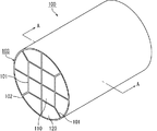
図1は、本発明の第一実施形態のハニカム構造体の一例を模式的に示す斜視図である。
図2は、図1に示したハニカム構造体のA−A線断面図である。
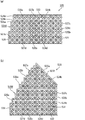
図3(a)は、本発明の第一実施形態のハニカム構造体を構成する内方ハニカム焼成体の一例を模式的に示す斜視図である。図3(b)は、図3(a)に示した内方ハニカム焼成体のB−B線断面図である。
図4(a)は、本発明の第一実施形態のハニカム構造体を構成する外方ハニカム焼成体の一例を模式的に示す斜視図である。図4(b)は、図4(a)に示した外方ハニカム焼成体の側面図である。
FIG. 1 is a perspective view schematically showing an example of the honeycomb structure of the first embodiment of the present invention.
FIG. 2 is a cross-sectional view of the honeycomb structure shown in FIG. 1 taken along line AA.
Fig.3 (a) is a perspective view which shows typically an example of the inner honeycomb fired body which comprises the honeycomb structure of 1st embodiment of this invention. Fig. 3 (b) is a cross-sectional view of the inner honeycomb fired body shown in Fig. 3 (a) taken along line BB.
Fig. 4 (a) is a perspective view schematically showing an example of an outer honeycomb fired body constituting the honeycomb structure according to the first embodiment of the present invention. Fig. 4 (b) is a side view of the outer honeycomb fired body shown in Fig. 4 (a).
図1及び図2に示すハニカム構造体100では、図3(a)及び図3(b)に示すような形状の4個の内方ハニカム焼成体110と、図4(a)及び図4(b)に示すような形状の8個の外方ハニカム焼成体120とが、接着材層101(101A〜101D)を介して結束されてセラミックブロック103を構成し、さらに、このセラミックブロック103の外周にコート層102が形成されている。なお、コート層は、必要に応じて形成されていればよい。
In the
外方ハニカム焼成体120の外周壁には、後述するように、凸部と凹部とからなる段差が設けられているため、セラミックブロック103の外周面には、段差が設けられていることになる。そして、セラミックブロック103の外周に形成されているコート層102は、段差に設けられた凹部を充填するように形成されている。
As will be described later, the outer peripheral wall of the outer honeycomb fired
図2に示すように、ハニカム構造体100は、その断面において、外方ハニカム焼成体120を結束する接着材層101C、101Dのうち、1つの内方ハニカム焼成体110の角部からハニカム構造体100の外周側面に向かう方向に形成されている接着材層101Cと、2つの内方ハニカム焼成体110の間からハニカム構造体100の外周側面に向かう方向に形成されている接着材層101Dとが、所定の角度(例えば、45°)をなしている。
As shown in FIG. 2, the
図2に示すように、内方ハニカム焼成体110は、断面の形状が略四角形(略正方形)からなる略四角形ユニットである。
また、図2に示すように、外方ハニカム焼成体120は、断面の形状が、3つの線分120a、120b、120cと1つの略円弧120dとで囲まれる形状からなる略扇形ユニットである。この3つの線分のうちの2つの線分よりなる2つの角(線分120bと線分120cとが成す角、及び、線分120aと線分120bとが成す角)は、それぞれ90°と135°である。なお、略円弧120dは、ハニカム構造体100の外周の一部を構成する。また、略円弧の形状については後述する。
As shown in FIG. 2, the inner honeycomb fired
As shown in FIG. 2, the outer honeycomb fired
以下、本発明の第一実施形態に係るハニカム構造体を構成する内方ハニカム焼成体、及び、外方ハニカム焼成体について説明する。
まず、内方ハニカム焼成体について説明する。
図3(a)及び図3(b)に示す内方ハニカム焼成体110には、多数のセル111がセル壁113を隔てて長手方向(図3(a)中、矢印aの方向)に並設されるとともに、その周囲に外周壁114a〜114dが形成されている。そして、セル111のいずれかの端部は、封止材112で封止されている。
Hereinafter, the inner honeycomb fired body and the outer honeycomb fired body constituting the honeycomb structure according to the first embodiment of the present invention will be described.
First, the inner honeycomb fired body will be described.
In the inner honeycomb fired
従って、一方の端面が開口したセル111に流入した排ガスG(図3(b)中、排ガスをGで示し、排ガスの流れを矢印で示す)は、必ずセル111を隔てるセル壁113を通過した後、他方の端面が開口した他のセル111から流出するようになっている。排ガスGがセル壁113を通過する際に、排ガス中のPM等が捕集されるため、セル壁113は、フィルタとして機能する。
Therefore, the exhaust gas G (in FIG. 3B, the exhaust gas is indicated by G and the flow of the exhaust gas is indicated by an arrow in FIG. 3B) always passes through the
内方ハニカム焼成体110のセル111の長手方向に垂直な断面の形状は、すべて略四角形(略正方形)であるとともに、セル111の断面積は、互いに等しい。また、セル111が規則正しく並ぶようにセル111が形成されている。
The cross-sectional shapes perpendicular to the longitudinal direction of the
次に、外方ハニカム焼成体について説明する。
図4(a)及び図4(b)に示す外方ハニカム焼成体120においても、内方ハニカム焼成体と同様、多数のセル121、127a〜127dが、セル壁123を隔てて長手方向(図4(a)中、矢印bの方向)に並設されるとともに、その周囲に外周壁124a〜124dが形成されている。そして、セル121、127a〜127dのいずれかの端部は、封止材122で封止されている。
従って、例えば、一方の端面が開口したセル121に流入した排ガスは、必ずセル121を隔てるセル壁123を通過した後、他方の端面が開口した他のセル121から流出するようになっており、セル壁123は、フィルタとして機能する。すなわち、外方ハニカム焼成体120は、外観形状が内方ハニカム焼成体110と異なるものの、そのフィルタ機能は内方ハニカム焼成体110と同一である。
Next, the outer honeycomb fired body will be described.
Also in the outer honeycomb fired
Therefore, for example, the exhaust gas that has flowed into the
外方ハニカム焼成体120において、セル121、127a〜127dは、外周壁124a〜124dに接する外周セル127a〜127dと、外周セル127a〜127dより内側に位置する内側セル121とからなる。
In the outer honeycomb fired
内側セル121は、基本形成パターンとして格子状に形成されている。それぞれの内側セル121の断面形状は、略四角形(略正方形)であるとともに、断面積は、互いに等しい。このように、内側セル121は、基本形成パターンに基づいて形成されているため、すべて完全セルとなっている。
The
外周セル127a〜127dのうち、ハニカム構造体(セラミックブロック)の外周を構成する外周壁124aに接する外周セル127aは、内側セル121と同じ断面形状を有している。また、外周壁124bに接する外周セル127b、及び、外周壁124cに接する外周セル127cも、内側セル121と同じ断面形状を有している。
つまり、外周セル127a〜127cは、完全セルである。これは、内側セル121が、その基本形成パターンを維持したまま外周壁124a〜124cに接することで、内側セル121が、そのまま外周セル127a〜127cになったと考えることができるためである。
一方、外周壁124dに接する外周セル127dは、断面の形状が、完全セルである内側セル121とは異なる不完全セルである。
上述したように、基本形成パターンに基づいて形成されていないセル、すなわち、基本形成パターンである内側セルの略四角形(略正方形)よりも長手方向に垂直な断面の大きさが小さいセルを不完全セルということとする。
Out of the outer
That is, the
On the other hand, the outer
As described above, cells that are not formed based on the basic formation pattern, that is, cells that have a smaller cross-sectional size perpendicular to the longitudinal direction than the substantially square (substantially square) of the inner cell that is the basic formation pattern are incomplete. This is a cell.
前述したように、外方ハニカム焼成体の外周のうち、ハニカム構造体の外周を構成する外周の長手方向に垂直な断面の形状は、略円弧状となっている。
具体的には、外方ハニカム焼成体の外周のうち、ハニカム構造体(セラミックブロック)の外周を構成する外周の長手方向に垂直な断面が、曲線部と直線部とを少なくとも含んでいる。
図4(a)及び図4(b)に示した外方ハニカム焼成体120では、外周120a〜120dのうち、ハニカム構造体(セラミックブロック)の外周を構成する外周120dの断面が、曲線部125a、125bと直線部126とを含む例を示している。
As described above, of the outer periphery of the outer honeycomb fired body, the shape of the cross section perpendicular to the longitudinal direction of the outer periphery constituting the outer periphery of the honeycomb structure is a substantially arc shape.
Specifically, of the outer periphery of the outer honeycomb fired body, a cross section perpendicular to the longitudinal direction of the outer periphery constituting the outer periphery of the honeycomb structure (ceramic block) includes at least a curved portion and a straight portion.
In the outer honeycomb fired
まず、外方ハニカム焼成体の直線部について説明する。
本実施形態において、外方ハニカム焼成体の直線部は、外方ハニカム焼成体及び隣り合う内方ハニカム焼成体の間の接着材層、並びに、外方ハニカム焼成体及び隣り合う外方ハニカム焼成体の間の接着材層の少なくとも一方に平行である。
図4(a)及び図4(b)に示す外方ハニカム焼成体120では、直線部126は、外周120dの一部であり、連続する6個のセル121に接する外周壁124aにより形成されている。また、直線部126は、セラミックブロックの外周を構成する外周120dの端部に設けられている。
また、外方ハニカム焼成体120の外周120dの一部を構成する直線部126は、対向する外周120bに平行である。図2に示したように、外方ハニカム焼成体120は、外周120bの部分において、接着材層101Bを介して内方ハニカム焼成体110と結束されている。従って、外方ハニカム焼成体120の直線部126は、内方ハニカム焼成体及び外方ハニカム焼成体の間の接着材層に平行であるといえる。
First, the straight part of the outer honeycomb fired body will be described.
In the present embodiment, the straight portion of the outer honeycomb fired body includes an adhesive layer between the outer honeycomb fired body and the adjacent inner honeycomb fired body, and the outer honeycomb fired body and the adjacent outer honeycomb fired body. Parallel to at least one of the adhesive layers between.
In the outer honeycomb fired
Further, the
なお、本明細書において、外方ハニカム焼成体の直線部は、外方ハニカム焼成体の外周の断面形状が、完全な直線のみからなる厳密な形状であることを意味するものではなく、直線と実質的に同視し得る形状を包含する。また、本明細書において、「平行」とは、数学的に厳密な関係を意味するものではなく、「平行」と実質的に同視し得る関係を包含する。 In the present specification, the straight portion of the outer honeycomb fired body does not mean that the cross-sectional shape of the outer periphery of the outer honeycomb fired body is a strict shape including only a complete straight line. Includes shapes that can be substantially equated. In this specification, “parallel” does not mean a mathematically exact relationship, but includes a relationship that can be substantially equated with “parallel”.
本実施形態において、外方ハニカム焼成体の直線部の長さは、5〜20mmが望ましい。また、外方ハニカム焼成体の直線部の長さは、5〜10個のセルの長さと略同一であることが望ましい。
本明細書においては、セルの長さを以下のように定義する。
図5は、図4(a)及び(b)に示す外方ハニカム焼成体の直線部近傍を模式的に示す側面図である。
セル121aの長さとは、セル121aとセル121bとを隔てるセル壁123aにおいて、その厚さの2等分線から、セル121aとセル123cとを隔てるセル壁123bにおいて、その厚さの2等分線までの距離(図5中、矢印Xで示す長さ)を指すこととする。
In this embodiment, the length of the straight portion of the outer honeycomb fired body is preferably 5 to 20 mm. Further, the length of the straight portion of the outer honeycomb fired body is preferably substantially the same as the length of 5 to 10 cells.
In this specification, the length of a cell is defined as follows.
FIG. 5 is a side view schematically showing the vicinity of a straight portion of the outer honeycomb fired body shown in FIGS. 4 (a) and 4 (b).
The length of the
次に、外方ハニカム焼成体の曲線部について説明する。
図4(a)及び図4(b)に示す外方ハニカム焼成体120では、外周壁124aは、外周セル127aの位置に対応して、凸部125aと凹部125bとからなる段差が設けられた外周壁となっている。そして、凸部125a及び凹部125bの断面の形状は、凸部125a及び凹部125bに面取りが施された形状となっている。従って、外方ハニカム焼成体120では、面取りが施された部分、すなわち、凸部125a及び凹部125bが外方ハニカム焼成体120の曲線部である。
面取りの断面形状としては、断面形状が曲線により構成されるR面取り(曲線の角部)が望ましい。
また、R面取りの曲率半径は、0.3〜2.5mmであることが望ましい。R面取りの曲率半径がこの範囲にあると、外方ハニカム焼成体が治具等と接触することにより発生する欠け等の破損が発生しにくく、外方ハニカム焼成体のセル壁の強度も向上しやすいからである。
なお、R面取りの曲率半径とは、R面取りにおける円弧の半径を意味する。
Next, the curved portion of the outer honeycomb fired body will be described.
In the outer honeycomb fired
As the chamfered cross-sectional shape, an R-chamfer (curved corner) in which the cross-sectional shape is a curve is desirable.
Further, the radius of curvature of the R chamfer is preferably 0.3 to 2.5 mm. When the radius of curvature of the R chamfer is within this range, breakage such as chipping caused when the outer honeycomb fired body comes into contact with a jig or the like is less likely to occur, and the strength of the cell wall of the outer honeycomb fired body is also improved. It is easy.
The radius of curvature of the R chamfer means the radius of the arc in the R chamfer.
なお、図4(a)及び図4(b)に示す外方ハニカム焼成体120において、曲線部である凸部125a及び凹部126bを角部と考えることもできる。その場合、ハニカム構造体の外周に、角部が形成されているということができる。そして、角部以外の外周壁124aの厚さ(角部以外のハニカム構造体の外周壁の厚さ)は、外周壁124aの全体に渡って略同じである。さらに、角部以外の外周壁124aの厚さは、セル壁123及び他の外周壁124b〜124dの厚さと略同じである。
In addition, in the outer honeycomb fired
本明細書において、外方ハニカム焼成体の外周壁に設けられている凸部に面取りが施されているとは、凸部の断面形状が、突出した外周壁の角部が削られた形状になっていることをいう。
一方、外方ハニカム焼成体の外周壁に設けられている凹部に面取りが施されているとは、凹部の断面形状が、外周壁の陥入した角部が擬似的に面取りを施された形状と同じ形状になるように、外周壁の角部が充填されたような形状になっていることをいう。例えば、外方ハニカム焼成体の外周壁の陥入した角部が擬似的にR面取り(曲線の角部)を施された形状と同じ形状になっていれば、凹部にR面取り(曲線の角部)が施されているという。
In the present specification, chamfering is applied to the convex portion provided on the outer peripheral wall of the outer honeycomb fired body, so that the cross-sectional shape of the convex portion is a shape in which the corner portion of the protruding outer peripheral wall is cut off. It means that
On the other hand, chamfering is applied to the recessed portion provided on the outer peripheral wall of the outer honeycomb fired body, and the cross-sectional shape of the recessed portion is a shape in which the corner portion where the outer peripheral wall is indented is artificially chamfered It is said that it is the shape where the corner | angular part of the outer peripheral wall was filled so that it might become the same shape. For example, if the corner part where the outer peripheral wall of the outer honeycomb fired body is indented has the same shape as the shape that has been pseudo-curved (curved corner part), the concave part has an R chamfered (curved corner) Part) is given.
なお、外方ハニカム焼成体の曲線部としては、図4(a)及び図4(b)に示したような、凸部及び凹部に限定されない。例えば、以下のような形状であってもよい。
図6(a)は、本発明の第一実施形態のハニカム構造体を構成する外方ハニカム焼成体の別の一例を模式的に示す斜視図である。図6(b)は、図6(a)に示した外方ハニカム焼成体の側面図である。
図6(a)及び(b)に示す外方ハニカム焼成体130においても、図4(a)及び図4(b)に示した外方ハニカム焼成体120と同様、多数のセル131、137a〜137dが、セル壁133を隔てて長手方向(図6(a)中、矢印cの方向)に並設されるとともに、その周囲に外周壁134a〜134dが形成されている。
セル131、137a〜137dのうち、セル131は内側セルであり、137a〜137dは外周セルである。
また、内側セル131は、すべて完全セルとなっている。
そして、外周セル137a〜137dのうち、セラミックブロックの外周を構成する外周壁134aに接する外周セル137aは、内側セル131と同じ断面形状を有している。
The curved portion of the outer honeycomb fired body is not limited to the convex portion and the concave portion as shown in FIGS. 4 (a) and 4 (b). For example, the following shapes may be used.
Fig. 6 (a) is a perspective view schematically showing another example of the outer honeycomb fired body constituting the honeycomb structure of the first embodiment of the present invention. FIG. 6B is a side view of the outer honeycomb fired body shown in FIG.
Also in the outer honeycomb fired
Of the
The
Out of the outer
また、外方ハニカム焼成体130においては、外周130a〜130dのうち、ハニカム構造体(セラミックブロック)の外周を構成する外周130dの断面に、直線部136が存在する。外方ハニカム焼成体130の直線部136は、外周130dの一部であり、連続する6個のセル131に接する外周壁134aにより形成されている。また、外周130dの一部を構成する直線部136は、対向する外周130bに平行である。従って、外方ハニカム焼成体130の直線部136は、外方ハニカム焼成体及び隣り合う内方ハニカム焼成体の間の接着材層に平行であるといえる。
Further, in the outer honeycomb fired
一方、外方ハニカム焼成体130では、図4(a)及び図4(b)に示した外方ハニカム焼成体120と異なり、外方ハニカム焼成体120において凹部125bであった部分が完全に充填されて、曲線部135となっている。
従って、図6(a)及び(b)に示す外方ハニカム焼成体130においては、外方ハニカム焼成体130の外周130a〜130dのうち、ハニカム構造体(セラミックブロック)の外周を構成する外周130dの断面が、曲線部135と直線部136とからなる。
On the other hand, in the outer honeycomb fired
Therefore, in the outer honeycomb fired
本実施形態において、曲線部は、外方ハニカム焼成体の外周のうち、セラミックブロックの外周を構成する外周の少なくとも1箇所に設けられていればよく、直線部の位置も限定されない。
図4(a)及び図4(b)に示す外方ハニカム焼成体120では、凸部125a及び凹部125bのすべてに面取りを施すことにより曲線部が設けられているが、凸部及び/又は凹部の少なくとも1箇所に面取りが施されていればよく、また、面取りの位置も限定されない。しかし、面取りが施されている箇所はなるべく多い方が望ましく、段差を構成する凸部及び凹部のすべての箇所について面取りが施されていることがより望ましい。
また、図6(a)及び図6(b)に示す外方ハニカム焼成体130では、凹部が完全に充填されているが、例えば、凹部の一部が充填されることにより、外周壁の一部に段差が設けられていてもよい。
このように、本実施形態においては、外方ハニカム焼成体において、外方ハニカム焼成体の外周のうち、セラミックブロックの外周を構成する外周の前記長手方向に垂直な断面が、曲線部と直線部とを少なくとも含んでいる限り、セラミックブロックの外周を構成する外周の断面形状は、特に限定されない。
また、外方ハニカム焼成体の外周のうち、セラミックブロックの外周を構成する外周の前記長手方向に垂直な断面が、曲線部と直線部とを少なくとも含んでいる外方ハニカム焼成体は、ハニカム構造体を構成する少なくとも1つの外方ハニカム焼成体であればよいが、すべての外方ハニカム焼成体であることが望ましい。
In the present embodiment, the curved portion only needs to be provided in at least one location on the outer periphery of the outer honeycomb fired body, and the position of the straight portion is not limited.
In the outer honeycomb fired
In addition, in the outer honeycomb fired
As described above, in the present embodiment, in the outer honeycomb fired body, of the outer periphery of the outer honeycomb fired body, the cross section perpendicular to the longitudinal direction of the outer periphery constituting the outer periphery of the ceramic block is a curved portion and a straight portion. The cross-sectional shape of the outer periphery constituting the outer periphery of the ceramic block is not particularly limited.
The outer honeycomb fired body in which the cross section perpendicular to the longitudinal direction of the outer periphery constituting the outer periphery of the ceramic block of the outer periphery of the outer honeycomb fired body includes at least a curved portion and a straight portion has a honeycomb structure. The outer honeycomb fired body may be at least one constituting the body, but all the outer honeycomb fired bodies are desirable.
本実施形態のハニカム構造体を構成する内方ハニカム焼成体及び外方ハニカム焼成体において、セルの内壁には、角部が形成されており、上記角部には、面取りが施されていてもよい。
セルの内壁に形成された角部(以下、単に「セルの角部」ともいう)に面取りが施されているとは、セルの断面形状が、セルの角部が擬似的に面取りを施された形状と同じ形状になるように、セルの角部が充填されたような形状になっていることをいう。
例えば、本実施形態では、セルの角部が、円弧(セルが擬似的にR面取りされた形状)、又は、C面取りされた形状(セルが擬似的にC面取りされた形状)であってもよい。
In the inner honeycomb fired body and the outer honeycomb fired body constituting the honeycomb structure of the present embodiment, corner portions are formed on the inner walls of the cells, and the corner portions may be chamfered. Good.
Chamfering is applied to the corner formed on the inner wall of the cell (hereinafter also referred to simply as “the corner of the cell”). The cross-sectional shape of the cell is artificially chamfered at the corner of the cell. The shape of the cell is filled with the corners of the cell so as to be the same shape.
For example, in the present embodiment, even if the corner portion of the cell is an arc (a shape in which the cell is pseudo R chamfered) or a C chamfered shape (a shape in which the cell is pseudo C chamfered) Good.
本実施形態のハニカム構造体を構成する内方ハニカム焼成体及び外方ハニカム焼成体は、炭化ケイ素又はケイ素含有炭化ケイ素からなる多孔質体であることが好ましい。 The inner honeycomb fired body and the outer honeycomb fired body constituting the honeycomb structure of the present embodiment are preferably porous bodies made of silicon carbide or silicon-containing silicon carbide.
次に、本実施形態のハニカム構造体の製造方法について説明する。
本実施形態のハニカム構造体の製造方法は、
セラミック原料を成形することにより、多数のセルがセル壁を隔てて長手方向に並設されたハニカム成形体を作成する成形工程と、
上記ハニカム成形体を焼成してハニカム焼成体を作製する焼成工程と、
複数の上記ハニカム焼成体を接着材層を介して接着させてセラミックブロックを作製する結束工程とを含むハニカム構造体の製造方法であって、
上記ハニカム焼成体として、外方ハニカム焼成体と内方ハニカム焼成体を作製し、
上記成形工程及び上記焼成工程において、外方ハニカム焼成体は、少なくとも第1の外周と第2の外周とを有し、
上記外方ハニカム焼成体の第1の外周の上記長手方向に垂直な断面が、曲線部と直線部とを少なくとも含み、
上記外方ハニカム焼成体の直線部が、対向する上記外方ハニカム焼成体の第2の外周と平行であり、上記外方ハニカム焼成体の直線部の長さが、5〜20mmとなるように作製し、
上記結束工程において、上記外方ハニカム焼成体を、上記外方ハニカム焼成体の直線部と上記外方ハニカム焼成体の第2の外周とを把持することにより、上記内方ハニカム焼成体の周囲に上記外方ハニカム焼成体が位置するように、かつ、上記外方ハニカム焼成体の直線部が上記セラミックブロックの最外周になるように配置することを特徴とする。
Next, a method for manufacturing the honeycomb structure of the present embodiment will be described.
The method for manufacturing the honeycomb structure of the present embodiment is as follows.
By forming a ceramic raw material, a forming step of creating a honeycomb formed body in which a large number of cells are arranged in parallel in the longitudinal direction across the cell wall;
A firing step of firing the honeycomb formed body to produce a honeycomb fired body;
A method of manufacturing a honeycomb structure including a bundling step in which a plurality of honeycomb fired bodies are bonded through an adhesive layer to produce a ceramic block,
As the honeycomb fired body, an outer honeycomb fired body and an inner honeycomb fired body are produced,
In the forming step and the firing step, the outer honeycomb fired body has at least a first outer periphery and a second outer periphery,
The cross section perpendicular to the longitudinal direction of the first outer periphery of the outer honeycomb fired body includes at least a curved portion and a straight portion,
The straight portion of the outer honeycomb fired body is parallel to the second outer periphery of the opposed outer honeycomb fired body, and the length of the straight portion of the outer honeycomb fired body is 5 to 20 mm. Make and
In the binding step, the outer honeycomb fired body is held around the inner honeycomb fired body by gripping the straight portion of the outer honeycomb fired body and the second outer periphery of the outer honeycomb fired body. The outer honeycomb fired body is positioned so that the straight portion of the outer honeycomb fired body is located on the outermost periphery of the ceramic block.
以下、本実施形態のハニカム構造体の製造方法を工程順に説明する。なお、セラミック粉末として、炭化ケイ素を用いる場合について説明する。
(1)セラミック原料を成形することによりハニカム成形体を作成する成形工程を行う。
具体的には、まず、セラミック粉末としての平均粒子径の異なる炭化ケイ素粉末と、有機バインダと、液状の可塑剤と、潤滑剤と、水とを混合することにより、ハニカム成形体製造用のセラミック原料(湿潤混合物)を調製する。
続いて、上記湿潤混合物を押出成形機に投入し、押出成形することにより所定の形状のハニカム成形体を作製する。
Hereinafter, the manufacturing method of the honeycomb structure of the present embodiment will be described in the order of steps. The case where silicon carbide is used as the ceramic powder will be described.
(1) A forming step of forming a honeycomb formed body by forming a ceramic raw material is performed.
Specifically, a ceramic for manufacturing a honeycomb formed body is first prepared by mixing silicon carbide powder having a different average particle size as a ceramic powder, an organic binder, a liquid plasticizer, a lubricant, and water. Prepare the raw material (wet mixture).
Subsequently, the wet mixture is put into an extruder and extruded to produce a honeycomb formed body having a predetermined shape.
ここで、断面が略四角形(略正方形)のハニカム成形体(内方ハニカム焼成体となるハニカム成形体)や、断面が3つの線分と1つの略円弧とで囲まれ、この3つの線分のうちの2つの線分よりなる2つの角がそれぞれ90°と135°である形状のハニカム成形体(外方ハニカム焼成体となるハニカム成形体)を作製するためには、それぞれの形状に応じた押出成形用金型を使用する。
以下の工程で、ハニカム成形体というときは、これら2種のハニカム成形体を区別せずに指すものとする。
Here, a honeycomb molded body having a substantially square (substantially square) cross section (a honeycomb molded body serving as an inner honeycomb fired body) or a cross section is surrounded by three line segments and one substantially circular arc. In order to produce a honeycomb formed body having a shape in which two angles of two of the line segments are 90 ° and 135 ° respectively (a honeycomb formed body that is an outer honeycomb fired body), Use an extrusion mold.
In the following steps, the term “honeycomb molded body” refers to these two types of honeycomb molded bodies without distinction.
(2)次に、ハニカム成形体を所定の長さに切断し、マイクロ波乾燥機、熱風乾燥機、誘電乾燥機、減圧乾燥機、真空乾燥機、凍結乾燥機等を用いて乾燥させた後、所定のセルに封止材となる封止材ペーストを充填して上記セルを目封じする封止工程を行う。
ここで、封止材ペーストとしては、上記湿潤混合物を用いることができる。
(2) Next, the honeycomb formed body is cut into a predetermined length and dried using a microwave dryer, hot air dryer, dielectric dryer, vacuum dryer, vacuum dryer, freeze dryer, or the like. Then, a sealing step of filling a predetermined cell with a sealing material paste as a sealing material and sealing the cell is performed.
Here, the wet mixture can be used as the sealing material paste.
(3)その後、ハニカム成形体を脱脂炉中で加熱し、ハニカム成形体中の有機物を除去し、焼成炉に搬送し、焼成工程を行うことにより、図3(a)及び図3(b)に示したような内方ハニカム焼成体、及び、図4(a)及び図4(b)に示したような外方ハニカム焼成体を作製する。
また、切断工程、乾燥工程、封止工程、脱脂工程及び焼成工程の条件は、従来からハニカム焼成体を作製する際に用いられている条件を適用することができる。
(3) After that, the honeycomb formed body is heated in a degreasing furnace to remove organic substances in the honeycomb formed body, transported to a firing furnace, and a firing process is performed, whereby FIG. 3 (a) and FIG. 3 (b). An inner honeycomb fired body as shown in FIG. 4 and an outer honeycomb fired body as shown in FIGS. 4A and 4B are manufactured.
Moreover, the conditions currently used when manufacturing a honeycomb fired body can be applied to the conditions of a cutting process, a drying process, a sealing process, a degreasing process, and a firing process.
(4)続いて、各セルの所定の端部が封止された内方ハニカム焼成体及び外方ハニカム焼成体のそれぞれの所定の側面に、接着材ペーストを塗布して接着材ペースト層を形成し、この接着材ペースト層の上に、順次他のハニカム焼成体を積層する工程を繰り返して所定数のハニカム焼成体が結束されたセラミックブロックを作製する結束工程を行う。
ここで、接着材ペーストとしては、例えば、無機バインダと有機バインダと無機粒子とからなるものを使用する。また、上記接着材ペーストは、さらに無機繊維及び/又はウィスカを含んでいてもよい。
(4) Subsequently, an adhesive paste layer is formed by applying an adhesive paste to predetermined side surfaces of the inner honeycomb fired body and the outer honeycomb fired body in which predetermined end portions of the respective cells are sealed. Then, a step of laminating other honeycomb fired bodies sequentially on this adhesive paste layer is repeated to perform a binding step for producing a ceramic block in which a predetermined number of honeycomb fired bodies are bound.
Here, as the adhesive paste, for example, a paste made of an inorganic binder, an organic binder, and inorganic particles is used. The adhesive paste may further contain inorganic fibers and / or whiskers.
この結束工程においては、中央部に内方ハニカム焼成体を配置し、その周囲に外方ハニカム焼成体を配置して、図1及び図2に示したようなセラミックブロックを作製する。
また、外方ハニカム焼成体を、外周に設けられた直線部がセラミックブロックの最外周になるように配置する。
この際、外方ハニカム焼成体の外周に設けられた直線部において、外方ハニカム焼成体の側面を把持する。
In this bundling step, the inner honeycomb fired body is disposed in the central portion, and the outer honeycomb fired body is disposed around the inner honeycomb fired body, so that a ceramic block as shown in FIGS. 1 and 2 is manufactured.
In addition, the outer honeycomb fired body is disposed so that the straight portion provided on the outer periphery is the outermost periphery of the ceramic block.
At this time, the side surface of the outer honeycomb fired body is gripped by the straight portion provided on the outer periphery of the outer honeycomb fired body.
(5)その後、略円柱状としたセラミックブロックの外周面に、コート材ペーストを塗布し、乾燥、固化してコート層を形成するコート層形成工程を行う。
セラミックブロックの外周面にコート材ペーストを塗布する際には、外方ハニカム焼成体に設けられた凹部を充填するようにコート材ペーストを塗布する。
ここで、コート材ペーストとしては、上記接着材ペーストを使用することができる。なお、コート材ペーストして、上記接着材ペーストと異なる組成のペーストを使用してもよい。
なお、コート層は必ずしも設ける必要はなく、必要に応じて設ければよい。
以上の工程によって、本実施形態のハニカム構造体を製造することができる。
(5) After that, a coating layer forming step is performed in which a coating material paste is applied to the outer peripheral surface of the substantially cylindrical ceramic block, dried and solidified to form a coating layer.
When the coating material paste is applied to the outer peripheral surface of the ceramic block, the coating material paste is applied so as to fill the recesses provided in the outer honeycomb fired body.
Here, the above-mentioned adhesive paste can be used as the coating material paste. Note that a paste having a composition different from that of the adhesive paste may be used as the coating material paste.
Note that the coat layer is not necessarily provided, and may be provided as necessary.
Through the above steps, the honeycomb structure of the present embodiment can be manufactured.
以下、本実施形態のハニカム構造体の作用効果について列挙する。
(1)本実施形態のハニカム構造体では、外方ハニカム焼成体の外周のうち、セラミックブロックの外周を構成する外周の断面に、直線部が存在する。そして、上記直線部は、外方ハニカム焼成体及び隣り合う内方ハニカム焼成体の間の接着材層、並びに、外方ハニカム焼成体及び隣り合う外方ハニカム焼成体の間の接着材層の少なくとも一方に平行である。
そのため、複数個の外方ハニカム焼成体を結束させる際、外方ハニカム焼成体の外周に設けられた直線部において外方ハニカム焼成体の側面を容易に把持することができる。従って、外方ハニカム焼成体を把持した部分で発生する欠け若しくはクラック、又は、外方ハニカム焼成体が治具等と接触することにより発生する欠け若しくはクラック等の不良を防止することができる。その結果、ハニカム構造体の不良が低減するため、ハニカム構造体の製造効率を向上させることができる。
Hereinafter, effects of the honeycomb structure of the present embodiment will be listed.
(1) In the honeycomb structure of the present embodiment, a straight portion exists in a cross section of the outer periphery constituting the outer periphery of the ceramic block in the outer periphery of the outer honeycomb fired body. The linear portion includes at least an adhesive layer between the outer honeycomb fired body and the adjacent inner honeycomb fired body, and an adhesive layer between the outer honeycomb fired body and the adjacent outer honeycomb fired body. Parallel to one side.
Therefore, when bundling a plurality of outer honeycomb fired bodies, the side surfaces of the outer honeycomb fired bodies can be easily grasped at the straight portions provided on the outer periphery of the outer honeycomb fired bodies. Accordingly, it is possible to prevent defects such as chips or cracks generated at the portion holding the outer honeycomb fired body, or chips or cracks generated when the outer honeycomb fired body comes into contact with a jig or the like. As a result, since the defect of the honeycomb structure is reduced, the manufacturing efficiency of the honeycomb structure can be improved.
(2)本実施形態のハニカム構造体では、外方ハニカム焼成体の直線部の長さは、5〜20mmである。
そのため、外方ハニカム焼成体の直線部において外方ハニカム焼成体を好適に把持することができる。
(2) In the honeycomb structure of the present embodiment, the length of the straight portion of the outer honeycomb fired body is 5 to 20 mm.
Therefore, the outer honeycomb fired body can be suitably held at the straight portion of the outer honeycomb fired body.
(3)本実施形態のハニカム構造体では、外方ハニカム焼成体の直線部は、連続する5個以上10個以下の上記セルに接する外周壁により形成されている。
外方ハニカム焼成体の直線部が、連続する5個以上10個以下のセルに接する外周壁により形成されていると、充分な長さの直線部を確保することができる。そのため、当該直線部において外方ハニカム焼成体を好適に把持することができる。
(3) In the honeycomb structure of the present embodiment, the straight portion of the outer honeycomb fired body is formed by the outer peripheral wall in contact with 5 to 10 continuous cells.
When the straight portion of the outer honeycomb fired body is formed by the outer peripheral wall in contact with 5 to 10 continuous cells, a sufficient length of the straight portion can be secured. Therefore, the outer honeycomb fired body can be suitably held at the straight portion.
(4)本実施形態のハニカム構造体では、外方ハニカム焼成体の直線部は、セラミックブロックの外周を構成する外周の端部に位置している。
外方ハニカム焼成体の直線部が、セラミックブロックの外周を構成する外周の端部に位置していると、外方ハニカム焼成体を容易に把持することができる。
(4) In the honeycomb structure of the present embodiment, the linear portion of the outer honeycomb fired body is located at the outer peripheral end portion that forms the outer periphery of the ceramic block.
When the linear portion of the outer honeycomb fired body is positioned at the outer peripheral end portion constituting the outer periphery of the ceramic block, the outer honeycomb fired body can be easily held.
(5)本実施形態のハニカム構造体では、外方ハニカム焼成体の外周のうち、セラミックブロックの外周を構成する外周の断面に、曲線部が存在する。
外方ハニカム焼成体の外周断面が、直線部のみで構成されているとすると、外方ハニカム焼成体の外周には、凸部と凹部とからなる段差が多く存在することとなる。その場合、段差が設けられた外方ハニカム焼成体を把持する際、又は、治具等を用いて外方ハニカム焼成体を搬送する際等に、段差の凸部が欠けたり、段差の凹部にクラックが入ったりする等の不良が発生しやすいという問題がある。
一方、外方ハニカム焼成体の断面に曲線部が存在するハニカム構造体では、外方ハニカム焼成体の断面に曲線部が存在しないハニカム構造体に比べて、段差の凸部に発生する欠け、及び、段差の凹部に発生するクラック等の不良を抑えることができる。
(5) In the honeycomb structure of the present embodiment, a curved portion exists in a cross section of the outer periphery constituting the outer periphery of the ceramic block in the outer periphery of the outer honeycomb fired body.
If the outer peripheral cross section of the outer honeycomb fired body is composed of only straight portions, there will be many steps consisting of convex portions and concave portions on the outer periphery of the outer honeycomb fired body. In that case, when gripping the outer honeycomb fired body provided with a step, or when transporting the outer honeycomb fired body using a jig or the like, the convex part of the step is missing or the concave part of the step is There is a problem that defects such as cracks are likely to occur.
On the other hand, in the honeycomb structure in which a curved portion is present in the cross section of the outer honeycomb fired body, a chip generated in the convex portion of the step, compared to a honeycomb structure in which the curved portion is not present in the cross section of the outer honeycomb fired body, and It is possible to suppress defects such as cracks generated in the recesses of the step.
(6)本実施形態のハニカム構造体では、外方ハニカム焼成体において、セルが、外方ハニカム焼成体の外周壁に接する外周セルと、外周セルより内側に位置する内側セルとからなり、内側セルは、基本形成パターンに基づいて形成された完全セルであり、外周セルのうち、セラミックブロックの外周を構成する外周壁に接する外周セルは、長手方向に垂直な断面の形状が内側セルと同じである。
外方ハニカム焼成体が有するセルの断面形状がすべて同じであると、封止材ペーストを容易に充填することができる。その結果、封止材ペーストの充填不良が低減するため、ハニカム構造体の製造効率を向上させることができる。
(6) In the honeycomb structure of the present embodiment, in the outer honeycomb fired body, the cells are composed of outer peripheral cells in contact with the outer peripheral wall of the outer honeycomb fired body and inner cells positioned on the inner side of the outer peripheral cells. The cell is a complete cell formed on the basis of the basic formation pattern, and the outer peripheral cell in contact with the outer peripheral wall constituting the outer periphery of the ceramic block is the same as the inner cell in the cross section perpendicular to the longitudinal direction. It is.
When the cross-sectional shapes of the cells of the outer honeycomb fired body are all the same, the sealing material paste can be easily filled. As a result, since the filling failure of the plug material paste is reduced, the manufacturing efficiency of the honeycomb structure can be improved.
(7)本実施形態のハニカム構造体では、外方ハニカム焼成体の外周には、凸部と凹部とからなる角部が形成されており、外方ハニカム焼成体の外周壁のうち、角部以外の外方ハニカム焼成体の外周壁の厚さは、略同じである。
言い換えると、ハニカム構造体の外周壁のうち、セラミックブロックの外周を構成する外周壁の厚さが、ハニカム構造体の外周に形成されている角部以外の当該外周壁の厚さと略同じである。このような形状を有するハニカム焼成体を作製する場合、押出成形時においてハニカム成形体のセル壁が変形することを防ぐことができるため、セル壁の歪みのないハニカム構造体を製造することができる。その結果、ハニカム成形体の成形不良を低減することができ、ハニカム構造体の製造効率を向上させることができる。
(7) In the honeycomb structure of the present embodiment, corners including convex portions and concave portions are formed on the outer periphery of the outer honeycomb fired body, and the corner portions of the outer peripheral wall of the outer honeycomb fired body are formed. The thickness of the outer peripheral wall of the outer honeycomb fired body other than is substantially the same.
In other words, among the outer peripheral walls of the honeycomb structure, the thickness of the outer peripheral wall constituting the outer periphery of the ceramic block is substantially the same as the thickness of the outer peripheral wall other than the corners formed on the outer periphery of the honeycomb structure. . When manufacturing a honeycomb fired body having such a shape, it is possible to prevent the cell walls of the honeycomb formed body from being deformed during extrusion molding, and thus it is possible to manufacture a honeycomb structure without cell wall distortion. . As a result, defective formation of the honeycomb formed body can be reduced, and the manufacturing efficiency of the honeycomb structure can be improved.
(8)本実施形態のハニカム構造体では、外方ハニカム焼成体は、長手方向に垂直な断面の形状が3つの線分とセラミックブロックの外周の一部を構成する外周とからなる断面略扇形の形状であり、内方ハニカム焼成体は、長手方向に垂直な断面の形状が略四角形である。
上記形状を有する外方ハニカム焼成体及び内方ハニカム焼成体を用いると、従来のハニカム構造体を製造する場合よりも少ない数のハニカム焼成体でハニカム構造体を製造することができる。従って、所定の形状を有するハニカム構造体を容易に製造することができるため、ハニカム構造体の製造効率をより向上させることができ、ハニカム構造体の製造コストの低減につながる。
(8) In the honeycomb structure of the present embodiment, the outer honeycomb fired body has a substantially sectoral cross section in which the shape of the cross section perpendicular to the longitudinal direction is composed of three line segments and the outer periphery constituting a part of the outer periphery of the ceramic block. The inner honeycomb fired body has a substantially quadrangular cross-sectional shape perpendicular to the longitudinal direction.
When the outer honeycomb fired body and the inner honeycomb fired body having the above shapes are used, the honeycomb structure can be manufactured with a smaller number of honeycomb fired bodies than in the case of manufacturing the conventional honeycomb structure. Therefore, since the honeycomb structure having a predetermined shape can be easily manufactured, the manufacturing efficiency of the honeycomb structure can be further improved, and the manufacturing cost of the honeycomb structure can be reduced.
(実施例1)
以下、本発明の第一実施形態をより具体的に開示した実施例を示す。なお、本発明はこれらの実施例のみに限定されるものではない。
Example 1
Examples that more specifically disclose the first embodiment of the present invention will be described below. In addition, this invention is not limited only to these Examples.
(1)平均粒子径22μmを有する炭化ケイ素の粗粉末52.8重量%と、平均粒子径0.5μmの炭化ケイ素の微粉末22.6重量%とを混合し、得られた混合物に対して、アクリル樹脂2.1重量%、有機バインダ(メチルセルロース)4.6重量%、潤滑剤(日油社製 ユニルーブ)2.8重量%、グリセリン1.3重量%、及び、水13.8重量%を加えて混練して湿潤混合物を得た後、押出成形する成形工程を行った。
本工程では、図3(a)及び図3(b)に示した内方ハニカム焼成体110と同様の形状であって、セルの目封じをしていない生のハニカム成形体と、図4(a)及び図4(b)に示した外方ハニカム焼成体120と同様の形状であって、セルの目封じをしていない生のハニカム成形体とを作製した。
(1) A silicon carbide coarse powder of 52.8% by weight having an average particle size of 22 μm and a silicon carbide fine powder of 22.6% by weight of an average particle size of 0.5 μm were mixed, and the resulting mixture was mixed. 2.1% by weight of acrylic resin, 4.6% by weight of organic binder (methylcellulose), 2.8% by weight of lubricant (Unilube manufactured by NOF Corporation), 1.3% by weight of glycerin, and 13.8% by weight of water Was added and kneaded to obtain a wet mixture, followed by a molding step of extrusion molding.
In this step, a raw honeycomb molded body having the same shape as the inner honeycomb fired
(2)次いで、マイクロ波乾燥機を用いて上記生のハニカム成形体を乾燥させることにより、ハニカム成形体の乾燥体を作製した。その後、ハニカム成形体の乾燥体の所定のセルに、上記湿潤混合物と同様の組成の封止材ペーストを充填してセルの封止を行った。セルの封止を行った後、封止材ペーストを充填したハニカム成形体の乾燥体を再び乾燥機を用いて乾燥させた。 (2) Next, the dried honeycomb molded body was produced by drying the raw honeycomb molded body using a microwave dryer. After that, cells were sealed by filling predetermined cells of the dried honeycomb molded body with a sealing material paste having the same composition as the wet mixture. After sealing the cells, the dried honeycomb molded body filled with the plug paste was again dried using a dryer.
(3)セルの封止を行ったハニカム成形体の乾燥体を400℃で脱脂する脱脂処理を行い、さらに、常圧のアルゴン雰囲気下2200℃、3時間の条件で焼成処理を行った。
これにより、内方ハニカム焼成体と外方ハニカム焼成体とを作製した。
内方ハニカム焼成体は、多孔質炭化ケイ素焼結体からなり、気孔率が45%、平均気孔径が15μm、大きさが34.5mm×34.5mm×150mm、セルの数(セル密度)が46.5個/cm2(300個/inch2)、セル壁の厚さが0.25mm(10mil)、セルの長さ(図5中、矢印Xで示す長さ)が1.42mmである。
外方ハニカム焼成体も、多孔質炭化ケイ素焼結体からなり、気孔率、平均気孔径、セルの数(セル密度)、セル壁の厚さ及びセルの長さは、内方ハニカム焼成体と同一である。また、外方ハニカム焼成体は、断面が3つの線分と1つの円弧とで囲まれ、この3つの線分のうちの2つの線分よりなる2つの角が、それぞれ90°と135°である形状(図2で示した線分120a=20.8mm、線分120b=35.0mm、線分120c=35.7mm)を有している。外方ハニカム焼成体の円弧120dは、曲線部と直線部を有している。外方ハニカム焼成体の曲線部は、凸部及び凹部とからなる。凸部及び凹部には、R面取り(曲線の角部)が施されており、R面取りの曲率半径は、0.5mmである。また、外方ハニカム焼成体の直線部は、対向する線分120bと平行であり、外方ハニカム焼成体の直線部の長さは、8.52mmである。
(3) A degreasing treatment was performed by degreasing the dried honeycomb molded body after cell sealing at 400 ° C., and further, a firing treatment was performed at 2200 ° C. under a normal pressure argon atmosphere for 3 hours.
Thereby, an inner honeycomb fired body and an outer honeycomb fired body were produced.
The inner honeycomb fired body is formed of a porous silicon carbide sintered body, having a porosity of 45%, an average pore diameter of 15 μm, a size of 34.5 mm × 34.5 mm × 150 mm, and the number of cells (cell density). 46.5 cells / cm 2 (300 cells / inch 2 ), cell wall thickness is 0.25 mm (10 mil), and cell length (length indicated by arrow X in FIG. 5) is 1.42 mm. .
The outer honeycomb fired body is also made of a porous silicon carbide sintered body, and the porosity, average pore diameter, number of cells (cell density), cell wall thickness, and cell length are the same as those of the inner honeycomb fired body. Are the same. Further, the outer honeycomb fired body is surrounded by three line segments and one arc, and two corners formed by two of the three line segments are 90 ° and 135 °, respectively. It has a certain shape (
(4)内方ハニカム焼成体及び外方ハニカム焼成体の所定の側面に接着材ペーストを塗布し、この接着材ペーストを介して内方ハニカム焼成体を4個と、外方ハニカム焼成体を8個とを図1に示した配置になるように接着させることにより、ハニカム焼成体の集合体を作製した。
さらに、ハニカム焼成体の集合体を180℃、20分で接着材ペーストを乾燥固化させることにより、接着材層の厚さが1mmで円柱状のセラミックブロックを作製した。
ここで、接着材ペーストとしては、平均粒径0.6μmの炭化ケイ素粒子30.0重量%、シリカゾル(固形分30重量%)21.4重量%、カルボキシメチルセルロース8.0重量%、及び、水40.6重量%からなる接着材ペーストを使用した。
(4) Adhesive paste is applied to predetermined side surfaces of the inner honeycomb fired body and the outer honeycomb fired body, and four inner honeycomb fired bodies and eight outer honeycomb fired bodies are provided through the adhesive paste. The individual pieces were bonded so as to have the arrangement shown in FIG. 1 to produce an aggregate of honeycomb fired bodies.
Further, the aggregate of the honeycomb fired bodies was dried and solidified at 180 ° C. for 20 minutes to produce a cylindrical ceramic block having an adhesive layer thickness of 1 mm.
Here, as the adhesive paste, 30.0% by weight of silicon carbide particles having an average particle diameter of 0.6 μm, 21.4% by weight of silica sol (solid content 30% by weight), 8.0% by weight of carboxymethyl cellulose, and water An adhesive paste consisting of 40.6% by weight was used.
(5)上記(4)の工程で使用した接着材ペーストと同じ組成のコート材ペーストを用いて、セラミックブロックの外周部にコート材ペースト層を形成した。この際、外方ハニカム焼成体に設けられた凹部を充填するようにコート材ペーストを塗布した。
その後、このコート材ペースト層を120℃で乾燥固化して、外周にコート層が形成された直径143.8mm×長さ150mmの円柱状のハニカム構造体を製造した。
(5) A coating material paste layer was formed on the outer periphery of the ceramic block using a coating material paste having the same composition as the adhesive paste used in the step (4). At this time, the coating material paste was applied so as to fill the recesses provided in the outer honeycomb fired body.
Thereafter, this coating material paste layer was dried and solidified at 120 ° C. to produce a cylindrical honeycomb structure having a diameter of 143.8 mm and a length of 150 mm, on which the coating layer was formed on the outer periphery.
(第二実施形態)
以下、本発明の一実施形態である第二実施形態について説明する。
本実施形態のハニカム構造体を構成する内方ハニカム焼成体及び外方ハニカム焼成体は、本発明の第一実施形態のハニカム構造体を構成する内方ハニカム焼成体及び外方ハニカム焼成体と同様の外形形状を有する。また、セラミックブロック(ハニカム構造体)を構成する外方ハニカム焼成体及び内方ハニカム焼成体の組み合わせ方も、本発明の第一実施形態と同様である。
本発明の第一実施形態では、外方ハニカム焼成体において、セラミックブロックの外周を構成する外周壁に接する外周セルと、内側セルとは、同一の断面形状を有しているのに対し、本実施形態では、外方ハニカム焼成体において、セラミックブロックの外周を構成する外周壁に接する外周セルが、内側セルと異なる断面形状を有する不完全セルを含んでいる。
(Second embodiment)
Hereinafter, a second embodiment which is an embodiment of the present invention will be described.
The inner honeycomb fired body and the outer honeycomb fired body constituting the honeycomb structure of the present embodiment are the same as the inner honeycomb fired body and the outer honeycomb fired body constituting the honeycomb structure of the first embodiment of the present invention. It has the outer shape. The method of combining the outer honeycomb fired body and the inner honeycomb fired body constituting the ceramic block (honeycomb structure) is the same as that of the first embodiment of the present invention.
In the first embodiment of the present invention, in the outer honeycomb fired body, the outer peripheral cell in contact with the outer peripheral wall constituting the outer periphery of the ceramic block and the inner cell have the same cross-sectional shape. In the embodiment, in the outer honeycomb fired body, the outer peripheral cell in contact with the outer peripheral wall constituting the outer periphery of the ceramic block includes an incomplete cell having a cross-sectional shape different from that of the inner cell.
以下、本発明の第二実施形態のハニカム構造体を構成する外方ハニカム焼成体について説明する。
図7(a)は、本発明の第二実施形態のハニカム構造体を構成する外方ハニカム焼成体の一例を模式的に示す斜視図である。図7(b)は、図7(a)に示した外方ハニカム焼成体の側面図である。
Hereinafter, the outer honeycomb fired body constituting the honeycomb structure of the second embodiment of the present invention will be described.
FIG. 7A is a perspective view schematically showing an example of an outer honeycomb fired body constituting the honeycomb structure of the second embodiment of the present invention. Fig. 7 (b) is a side view of the outer honeycomb fired body shown in Fig. 7 (a).
図7(a)及び図7(b)に示す外方ハニカム焼成体220には、多数のセル221、227a〜227eが、セル壁223を隔てて長手方向(図7(a)中、矢印dの方向)に並設されるとともに、その周囲に外周壁224a〜224dが形成されている。そして、セル221、227a〜227eのいずれかの端部は、封止材222で封止されている。
従って、例えば、一方の端面が開口したセル221に流入した排ガスは、必ずセル221を隔てるセル壁223を通過した後、他方の端面が開口した他のセル221から流出するようになっており、セル壁223は、フィルタとして機能する。
In the outer honeycomb fired
Therefore, for example, the exhaust gas flowing into the
外方ハニカム焼成体220において、セル221、227a〜227eは、外周壁224a〜224dに接する外周セル227a〜227eと、外周セル227a〜227eより内側に位置する内側セル221とからなる。
In the outer honeycomb fired
外方ハニカム焼成体220の内側セル221は、基本形成パターンとして格子状に形成されている。それぞれの内側セル221の断面形状は、略四角形(略正方形)であるとともに、断面積は、互いに等しい。すなわち、内側セル221は、すべて完全セルとなっている。
The
外方ハニカム焼成体220の外周セル227a〜227eのうち、ハニカム構造体(セラミックブロック)の外周を構成する外周壁224aに接する外周セル227aは、断面形状が内側セル221と同じであり、ハニカム構造体(セラミックブロック)の外周を構成する外周壁224aに接する外周セル227eは、断面形状が内側セル221と異なる。つまり、外周セル227aは完全セルであり、外周セル227eは、不完全セルである。
Among the
本発明の第一実施形態と同様に、外周壁224bに接する外周セル227b、及び、外周壁224cに接する外周セル227cは、内側セル221と同じ断面形状を有している。つまり、外周セル227b及び227cは、完全セルである。
また、外周壁224dに接する外周セル227dは、断面の形状が、完全セルである内側セル221とは異なる不完全セルである。
Similar to the first embodiment of the present invention, the outer
The outer
このように、本実施形態では、外周セルのうち、セラミックブロックの外周を構成する外周壁に接する外周セルは、完全セルの他に、断面の形状が完全セルと異なる不完全セルを含んでいる。
そして、外周セルについて、不完全セルを除いた外周セルの断面形状は、内側セルと同様、略四角形(略正方形)であるとともに、断面積は、互いに等しい。
As described above, in this embodiment, among the peripheral cells, the peripheral cells in contact with the peripheral wall constituting the outer periphery of the ceramic block include incomplete cells having a cross-sectional shape different from the complete cells in addition to the complete cells. .
And about an outer periphery cell, the cross-sectional shape of the outer periphery cell except an incomplete cell is a substantially square (substantially square) similarly to an inner side cell, and a cross-sectional area is mutually equal.
本実施形態において、外周セルのうち、セラミックブロックの外周を構成する外周壁に接する外周セルは、少なくとも1つの不完全セルを含んでいればよく、不完全セルの個数は特に限定されない。すなわち、不完全セルは、外方ハニカム焼成体の外周壁の形状、及び、外周壁により規定される外周セルの形状を考慮して設ければよい。 In the present embodiment, among the peripheral cells, the peripheral cells in contact with the peripheral wall constituting the outer periphery of the ceramic block only need to include at least one incomplete cell, and the number of incomplete cells is not particularly limited. That is, the incomplete cell may be provided in consideration of the shape of the outer peripheral wall of the outer honeycomb fired body and the shape of the outer peripheral cell defined by the outer peripheral wall.
不完全セルの断面積は、特に限定されないが、不完全セルの断面積は、封止材ペーストを充填しやすく、封止不良が発生しない所定の大きさとすればよい。
具体的には、不完全セルは、セルの長手方向に垂直な断面形状の内部に直径0.90mmの円が挿入可能なセルであることが望ましく、セルの長手方向に垂直な断面形状の内部に直径0.95mmの円が挿入可能なセルであることがより望ましい。
このような場合、封止材ペーストをセルに充填しやすく、封止材ペーストの漏れ及びはみ出しが発生しにくく、良好に不完全セルを封止することができ、封止不良が発生しにくくなる。
The cross-sectional area of the incomplete cell is not particularly limited, but the cross-sectional area of the incomplete cell may be a predetermined size that facilitates filling with the sealing material paste and does not cause a sealing failure.
Specifically, the incomplete cell is desirably a cell in which a circle having a diameter of 0.90 mm can be inserted into the inside of the cross-sectional shape perpendicular to the longitudinal direction of the cell, and the inside of the cross-sectional shape perpendicular to the longitudinal direction of the cell. It is more preferable that the cell has a diameter of 0.95 mm.
In such a case, it is easy to fill the sealing material paste into the cell, the sealing material paste is less likely to leak and protrude, the incomplete cell can be well sealed, and sealing failure is less likely to occur. .
本実施形態においても、外方ハニカム焼成体の外周のうち、セラミックブロックの外周を構成する外周の長手方向に垂直な断面が、曲線部と直線部とを少なくとも含んでいる。
図7(a)及び図7(b)に示した外方ハニカム焼成体220では、外周220a〜220dのうち、セラミックブロックの外周を構成する外周220dの断面が、曲線部225a、225bと直線部226とを含む例を示している。
Also in the present embodiment, the cross section perpendicular to the longitudinal direction of the outer periphery constituting the outer periphery of the ceramic block in the outer periphery of the outer honeycomb fired body includes at least a curved portion and a straight portion.
In the outer honeycomb fired
外方ハニカム焼成体の直線部の構成は、本発明の第一実施形態と同様である。
外方ハニカム焼成体の直線部は、外方ハニカム焼成体及び隣り合う内方ハニカム焼成体の間の接着材層、並びに、外方ハニカム焼成体及び隣り合う外方ハニカム焼成体の間の接着材層の少なくとも一方に平行である。また、外方ハニカム焼成体の直線部の長さは、5〜20mmである。
図7(a)及び図7(b)に示す外方ハニカム焼成体220において、直線部226は、外周220dの一部であり、連続する6個のセル221に接する外周壁224aにより形成されている。
また、外周220dの一部を構成する直線部226は、対向する外周220bに平行である。従って、外方ハニカム焼成体220の直線部226は、内方ハニカム焼成体及び外方ハニカム焼成体の間の接着材層に平行であるといえる。
The configuration of the straight portion of the outer honeycomb fired body is the same as that of the first embodiment of the present invention.
The straight portion of the outer honeycomb fired body includes an adhesive layer between the outer honeycomb fired body and the adjacent inner honeycomb fired body, and an adhesive material between the outer honeycomb fired body and the adjacent outer honeycomb fired body. Parallel to at least one of the layers. Further, the length of the straight portion of the outer honeycomb fired body is 5 to 20 mm.
In the outer honeycomb fired
Moreover, the
外方ハニカム焼成体の曲線部の構成は、本発明の第一実施形態と同様である。
図7(a)及び図7(b)に示す外方ハニカム焼成体220では、外周壁224aは、外周セル227a、227eの位置に対応して、凸部225aと凹部225bとからなる段差が設けられた外周壁となっている。そして、凸部225a及び凹部225bの断面の形状は、凸部225a及び凹部225bに面取りが施された形状となっている。従って、外方ハニカム焼成体220では、面取りが施された部分、すなわち、凸部225a及び凹部225bが曲線部である。
The configuration of the curved portion of the outer honeycomb fired body is the same as that of the first embodiment of the present invention.
In the outer honeycomb fired
なお、外方ハニカム焼成体の曲線部としては、図6(a)及び図6(b)に示した外方ハニカム焼成体130のように、凹部が完全に充填されることにより曲線部が設けられていてもよい。また、凹部の一部が充填されることにより、外周壁の一部に段差が設けられていてもよい。
As the curved portion of the outer honeycomb fired body, a curved portion is provided by completely filling the concave portions as in the outer honeycomb fired
次に、本発明の第二実施形態のハニカム構造体を構成する内方ハニカム焼成体について説明する。
内方ハニカム焼成体は、本発明の第一実施形態で説明した内方ハニカム焼成体と同様である。
内方ハニカム焼成体に設けられたセルは、すべて完全セルとなっている。
Next, an inner honeycomb fired body constituting the honeycomb structure according to the second embodiment of the present invention will be described.
The inner honeycomb fired body is the same as the inner honeycomb fired body described in the first embodiment of the present invention.
All the cells provided in the inner honeycomb fired body are complete cells.
本実施形態のハニカム構造体を構成する内方ハニカム焼成体及び外方ハニカム焼成体において、セルの内壁には、角部が形成されており、上記角部には、面取りが施されていてもよい。
例えば、本実施形態では、セルの角部が、円弧(セルが擬似的にR面取りされた形状)、又は、直線(セルが擬似的にC面取りされた形状)であってもよい。
In the inner honeycomb fired body and the outer honeycomb fired body constituting the honeycomb structure of the present embodiment, corner portions are formed on the inner walls of the cells, and the corner portions may be chamfered. Good.
For example, in the present embodiment, the corner of the cell may be an arc (a shape in which the cell is artificially chamfered) or a straight line (a shape in which the cell is artificially chamfered).
本実施形態のハニカム構造体の製造方法においては、押出成形に用いる金型の形状を変更して所定の形状を有するハニカム成形体を作製する点以外は、本発明の第一実施形態と同様にしてハニカム構造体を作製することができる。 In the method for manufacturing a honeycomb structured body of the present embodiment, the method is the same as that of the first embodiment of the present invention except that a honeycomb molded body having a predetermined shape is manufactured by changing the shape of a mold used for extrusion molding. Thus, a honeycomb structure can be manufactured.
本実施形態では、本発明の第一実施形態において説明した効果(1)〜(5)、(7)及び(8)を発揮することができるとともに、以下の効果を発揮することができる。
(9)本実施形態のハニカム構造体では、外方ハニカム焼成体において、セルは、外方ハニカム焼成体の外周壁に接する外周セルと、外周セルより内側に位置する内側セルとからなり、内側セルは、基本形成パターンに基づいて形成された完全セルであり、外周セルのうち、セラミックブロックの外周を構成する外周壁に接する外周セルは、長手方向に垂直な断面の形状が内側セルと異なる不完全セルを含む。
ハニカム構造体が不完全セルを含んでいると、ハニカム構造体を排ガス浄化フィルタとして使用した場合、最大数のセルを配置することができるため、PMを捕集することができるろ過面積を向上させることができる。そのため、圧力損失の低いハニカム構造体とすることができる。
In the present embodiment, the effects (1) to (5), (7) and (8) described in the first embodiment of the present invention can be exhibited, and the following effects can be exhibited.
(9) In the honeycomb structure of the present embodiment, in the outer honeycomb fired body, the cell is composed of an outer peripheral cell in contact with the outer peripheral wall of the outer honeycomb fired body and an inner cell positioned on the inner side of the outer peripheral cell. The cell is a complete cell formed on the basis of the basic formation pattern, and the outer peripheral cell in contact with the outer peripheral wall constituting the outer periphery of the ceramic block is different from the inner cell in the cross-sectional shape perpendicular to the longitudinal direction. Contains incomplete cells.
When the honeycomb structure includes incomplete cells, when the honeycomb structure is used as an exhaust gas purification filter, the maximum number of cells can be arranged, so that the filtration area capable of collecting PM is improved. be able to. Therefore, a honeycomb structure with low pressure loss can be obtained.
(第三実施形態)
以下、本発明の一実施形態である第三実施形態について説明する。
本実施形態のハニカム構造体を構成する内方ハニカム焼成体及び外方ハニカム焼成体は、本発明の第二実施形態のハニカム構造体を構成する内方ハニカム焼成体及び外方ハニカム焼成体と同様の外形形状を有する。また、セラミックブロック(ハニカム構造体)を構成する外方ハニカム焼成体及び内方ハニカム焼成体の組み合わせ方も、本発明の第二実施形態と同様である。
本実施形態では、外方ハニカム焼成体の不完全セルを除いた外周セル、及び、外方ハニカム焼成体の内側セル、並びに、内方ハニカム焼成体のセルは、大容量セルと、小容量セルとからなり、大容量セルの長手方向に垂直な断面の面積は、小容量セルの長手方向に垂直な断面の面積よりも大きい。
(Third embodiment)
Hereinafter, a third embodiment which is an embodiment of the present invention will be described.
The inner honeycomb fired body and the outer honeycomb fired body constituting the honeycomb structure of the present embodiment are the same as the inner honeycomb fired body and the outer honeycomb fired body constituting the honeycomb structure of the second embodiment of the present invention. It has the outer shape. The combination of the outer honeycomb fired body and the inner honeycomb fired body constituting the ceramic block (honeycomb structure) is also the same as in the second embodiment of the present invention.
In the present embodiment, the outer peripheral cells excluding the incomplete cells of the outer honeycomb fired body, the inner cells of the outer honeycomb fired body, and the cells of the inner honeycomb fired body are large capacity cells and small capacity cells. The area of the cross section perpendicular to the longitudinal direction of the large capacity cell is larger than the area of the cross section perpendicular to the longitudinal direction of the small capacity cell.
図8(a)は、本発明の第三実施形態のハニカム構造体を構成する内方ハニカム焼成体の一例を模式的に示す側面図である。図8(b)は、本発明の第三実施形態のハニカム構造体を構成する外方ハニカム焼成体の一例を模式的に示す側面図である。 Fig.8 (a) is a side view which shows typically an example of the inner honeycomb fired body which comprises the honeycomb structure of 3rd embodiment of this invention. FIG. 8B is a side view schematically showing an example of the outer honeycomb fired body constituting the honeycomb structure of the third embodiment of the present invention.
まず、内方ハニカム焼成体について説明する。
図8(a)に示す内方ハニカム焼成体310には、セル311a、311bがセル壁313を隔てて並設されるとともに、その周囲に外周壁314a〜314dが形成されている。セル311a、311bは、大容量セル311aと、小容量セル311bとからなり、大容量セル311aの断面積(長手方向に垂直な断面の面積)は、小容量セル311bの断面積よりも大きくなっている。そして、大容量セル311aと小容量セル311bとは、交互に配設されている。
図8(a)において、大容量セル311aは、その断面形状が略八角形であり、小容量セル311bは、その断面形状が略四角形である。このように、セル311a、311bは、基本形成パターンに基づいて形成されているため、完全セルであるということができる。
First, the inner honeycomb fired body will be described.
In the inner honeycomb fired
8A, the
大容量セル311aは、内方ハニカム焼成体310の第一の端面側の端部が開放され、第二の端面側の端部で封止材(図示せず)により封止されている。一方、小容量セル311bは、内方ハニカム焼成体310の第一の端面側の端部で封止材312により封止され、第二の端面側の端部が開放されている。
従って、例えば、大容量セル311aに流入した排ガスは、必ず、大容量セル311aと小容量セル311bとを隔てるセル壁313を通過した後、小容量セル311bから流出するようになっており、セル壁313は、フィルタとして機能する。
In the
Therefore, for example, the exhaust gas flowing into the
次に、外方ハニカム焼成体について説明する。
図8(b)に示す外方ハニカム焼成体320においても、内方ハニカム焼成体と同様、セル321a、321b、327a〜327eがセル壁323を隔てて並設されるとともに、その周囲に外周壁324a〜324dが形成されている。
Next, the outer honeycomb fired body will be described.
Also in the outer honeycomb fired
外方ハニカム焼成体320において、セル321a、321b、327a〜327eは、外周壁324a〜324dに接する外周セル327a〜327eと、外周セル327a〜327eより内側に位置する内側セル321a、321bとからなる。
In the outer honeycomb fired
外方ハニカム焼成体320の内側セル321a、321bは、内方ハニカム焼成体310に設けられたセル311a、311bと同様、完全セルである。すなわち、完全セルである内側セル321a、321bは、大容量セル321aと、小容量セル321bとからなり、大容量セル321aの断面積(長手方向に垂直な断面の面積)は、小容量セル321bの断面積よりも大きくなっている。
そして、大容量セル321aは、外方ハニカム焼成体320の第一の端面側の端部が開放され、第二の端面側の端部で封止材(図示せず)により封止されている。一方、小容量セル321bは、外方ハニカム焼成体320の第一の端面側の端部で封止材322により封止され、第二の端面側の端部が開放されている。
従って、例えば、大容量セル321aに流入した排ガスは、必ず、大容量セル321aと小容量セル321bとを隔てるセル壁323を通過した後、小容量セル321bから流出するようになっており、セル壁323は、フィルタとして機能する。
The
In the
Therefore, for example, the exhaust gas flowing into the
外方ハニカム焼成体320の外周セル327a〜327eのうち、外周壁324aに接する外周セル327a、外周壁324bに接する外周セル327b、及び、外周壁324cに接する外周セル327cは、外方ハニカム焼成体320の内側セルである大容量セル321aと同じ断面形状を有している。つまり、外方ハニカム焼成体320の外周セル327a、327b及び327cは、完全セルである。
一方、外方ハニカム焼成体320の外周セル327a〜327eのうち、外周壁324dに接する外周セル327d、及び、外周壁324aに接する外周セル327eは、断面の形状が、外方ハニカム焼成体320の内側セルであって、かつ、完全セルである大容量セル321aとは異なる。すなわち、外方ハニカム焼成体320の外周セル327d、327eは、断面の形状が完全セルと異なる不完全セルである。
すなわち、図8(b)に示す外方ハニカム焼成体320においては、外周セルは、完全セルの他に、断面の形状が完全セルと異なる不完全セルを含んでいる。
図8(b)に示す外方ハニカム焼成体320においては、不完全セルを除いた外周セルは、内側セルと同様、大容量セルと小容量セルとからなる。
Out of the
On the other hand, among the outer
That is, in the outer honeycomb fired
In the outer honeycomb fired
なお、本実施形態においては、外周セルは、不完全セルを含んでいなくてもよい。その場合、本実施形態は、本発明の第一実施形態のセル形状として、断面積に大小関係のあるセルを採用した形態であるともいえる。 In the present embodiment, the angular cell may not include an incomplete cell. In that case, it can be said that this embodiment is a form in which a cell having a cross-sectional area is used as the cell shape of the first embodiment of the present invention.
大容量セル及び小容量セルの断面形状としては、大容量セルの断面積が小容量セルの断面積より大きくなっていればよい。そのため、大容量セル及び小容量セルの断面形状は、それぞれ略八角形及び略四角形である形状に限定されず、任意の断面形状を採用することができる。例えば、以下のような形状であってもよい。
図9(a)は、本発明の第三実施形態のハニカム構造体を構成する内方ハニカム焼成体の別の一例を模式的に示す側面図である。図9(b)は、本発明の第三実施形態のハニカム構造体を構成する外方ハニカム焼成体の別の一例を模式的に示す側面図である。
図9(a)に示す内方ハニカム焼成体330、及び、図9(b)に示す外方ハニカム焼成体340では、大容量セルの断面形状が略四角形(略正方形)であり、小容量セルの断面形状が略四角形(略正方形)である。
As a cross-sectional shape of the large-capacity cell and the small-capacity cell, the cross-sectional area of the large-capacity cell may be larger than that of the small-capacity cell. Therefore, the cross-sectional shapes of the large-capacity cell and the small-capacity cell are not limited to shapes that are substantially octagonal and substantially quadrangular, respectively, and any cross-sectional shape can be adopted. For example, the following shapes may be used.
FIG. 9A is a side view schematically showing another example of the inner honeycomb fired body constituting the honeycomb structure according to the third embodiment of the present invention. FIG. 9B is a side view schematically showing another example of the outer honeycomb fired body constituting the honeycomb structure of the third embodiment of the present invention.
In the inner honeycomb fired
なお、大容量セル及び小容量セルの断面形状は、直角部があってもよいし、直角部に相当する箇所が、円弧(セルが擬似的にR面取りされた形状)、又は、直線(セルが擬似的にC面取りされた形状)であってもよい。 The cross-sectional shapes of the large-capacity cell and the small-capacity cell may have a right-angle portion, and the portion corresponding to the right-angle portion may be a circular arc (a shape in which the cell is artificially chamfered) or a straight line (cell May be a C-chamfered shape).
本実施形態においても、外方ハニカム焼成体の外周のうち、セラミックブロックの外周を構成する外周の長手方向に垂直な断面が、曲線部と直線部とを少なくとも含んでいる。
図8(b)に示した外方ハニカム焼成体320では、外周320a〜320dのうち、セラミックブロックの外周を構成する外周320dの断面が、曲線部325a、325bと直線部326とを含む例を示している。同様に、図9(b)に示した外方ハニカム焼成体340では、外周340a〜340dのうち、セラミックブロックの外周を構成する外周340dの断面が、曲線部345a、345bと直線部346とを含む例を示している。
Also in the present embodiment, the cross section perpendicular to the longitudinal direction of the outer periphery constituting the outer periphery of the ceramic block in the outer periphery of the outer honeycomb fired body includes at least a curved portion and a straight portion.
In the outer honeycomb fired
外方ハニカム焼成体の直線部の構成は、本発明の第一実施形態と同様である。
外方ハニカム焼成体の直線部は、外方ハニカム焼成体及び隣り合う内方ハニカム焼成体の間の接着材層、並びに、外方ハニカム焼成体及び隣り合う外方ハニカム焼成体の間の接着材層の少なくとも一方に平行である。また、外方ハニカム焼成体の直線部の長さは、5〜20mmである。
図8(b)に示す外方ハニカム焼成体320において、直線部326は、外周320dの一部であり、対向する外周320bに平行である。従って、外方ハニカム焼成体320の直線部326は、内方ハニカム焼成体及び外方ハニカム焼成体の間の接着材層に平行であるといえる。図9(b)に示す外方ハニカム焼成体340においても同様である。
The configuration of the straight portion of the outer honeycomb fired body is the same as that of the first embodiment of the present invention.
The straight portion of the outer honeycomb fired body includes an adhesive layer between the outer honeycomb fired body and the adjacent inner honeycomb fired body, and an adhesive material between the outer honeycomb fired body and the adjacent outer honeycomb fired body. Parallel to at least one of the layers. Further, the length of the straight portion of the outer honeycomb fired body is 5 to 20 mm.
In the outer honeycomb fired
外方ハニカム焼成体の曲線部の構成は、本発明の第一実施形態と同様である。
図8(b)に示す外方ハニカム焼成体320では、外周セル327a、327eの位置に対応して、凸部325aと凹部325bとからなる段差が設けられた外周壁となっている。そして、凸部325a及び凹部325bの断面の形状は、凸部325a及び凹部325bに面取りが施された形状となっている。従って、外方ハニカム焼成体320では、面取りが施された部分、すなわち、凸部325a及び凹部325bが曲線部である。図9(b)に示す外方ハニカム焼成体340においても同様である。
The configuration of the curved portion of the outer honeycomb fired body is the same as that of the first embodiment of the present invention.
The outer honeycomb fired
なお、外方ハニカム焼成体の曲線部としては、図6(a)及び図6(b)に示した外方ハニカム焼成体130のように、凹部が完全に充填されることにより曲線部が設けられていてもよい。また、凹部の一部が充填されることにより、外周部の一部に段差が設けられていてもよい。
As the curved portion of the outer honeycomb fired body, a curved portion is provided by completely filling the concave portions as in the outer honeycomb fired
本実施形態のハニカム構造体を構成する内方ハニカム焼成体及び外方ハニカム焼成体において、セルの内壁には、角部が形成されており、上記角部には、面取りが施されていてもよい。
例えば、本実施形態では、セルの角部が、円弧(セルが擬似的にR面取りされた形状)、又は、直線(セルが擬似的にC面取りされた形状)であってもよい。
In the inner honeycomb fired body and the outer honeycomb fired body constituting the honeycomb structure of the present embodiment, corner portions are formed on the inner walls of the cells, and the corner portions may be chamfered. Good.
For example, in the present embodiment, the corner of the cell may be an arc (a shape in which the cell is artificially chamfered) or a straight line (a shape in which the cell is artificially chamfered).
本実施形態のハニカム構造体の製造方法においては、押出成形に用いる金型の形状を変更して所定の形状を有するハニカム成形体を作製する点以外は、本発明の第一実施形態と同様にしてハニカム構造体を作製することができる。 In the method for manufacturing a honeycomb structured body of the present embodiment, the method is the same as that of the first embodiment of the present invention except that a honeycomb molded body having a predetermined shape is manufactured by changing the shape of a mold used for extrusion molding. Thus, a honeycomb structure can be manufactured.
本実施形態においても、本発明の第一実施形態において説明した効果(1)〜(5)、(7)及び(8)、並びに、本発明の第二実施形態において説明した効果(9)を発揮することができるとともに、以下の効果を発揮することができる。
(10)本実施形態のハニカム構造体では、外方ハニカム焼成体の不完全セルを除いた外周セル、外方ハニカム焼成体の内側セル、及び、内方ハニカム焼成体のセルは、大容量セルと、小容量セルとからなり、大容量セルの長手方向に垂直な断面の面積は、小容量セルの長手方向に垂直な断面の面積よりも大きい。
このようなハニカム構造体では、排ガス浄化用フィルタとして用いた際に、大量のPMを捕集することができる。
Also in this embodiment, the effects (1) to (5), (7) and (8) described in the first embodiment of the present invention, and the effect (9) described in the second embodiment of the present invention. While being able to demonstrate, the following effects can be exhibited.
(10) In the honeycomb structure of the present embodiment, the outer peripheral cells excluding the incomplete cells of the outer honeycomb fired body, the inner cells of the outer honeycomb fired body, and the cells of the inner honeycomb fired body are large-capacity cells. And the area of the cross section perpendicular to the longitudinal direction of the large capacity cell is larger than the area of the cross section perpendicular to the longitudinal direction of the small capacity cell.
In such a honeycomb structure, a large amount of PM can be collected when used as an exhaust gas purification filter.
(第四実施形態)
以下、本発明の一実施形態である第四実施形態について説明する。
本実施形態では、内方ハニカム焼成体の外形形状は、本発明の第一実施形態〜第三実施形態と同様であるが、外方ハニカム焼成体の外形形状が、本発明の第一実施形態〜第三実施形態と異なる。
具体的には、本実施形態では、ハニカム焼成体の組み合わせ構造が、本発明の第一実施形態〜第三実施形態と異なる。すなわち、内方ハニカム焼成体として、略四角形(略正方形)の断面形状を有するハニカム焼成体を用い、外方ハニカム焼成体として、断面形状の異なる複数種類の所定形状のハニカム焼成体を用いる。そして、内方ハニカム焼成体と複数種類の外方ハニカム焼成体とを接着材層を介して組み立てることにより、所定形状(例えば、断面略円形等)のセラミックブロックを形成することができる。
(Fourth embodiment)
Hereinafter, a fourth embodiment which is an embodiment of the present invention will be described.
In this embodiment, the outer shape of the inner honeycomb fired body is the same as that of the first to third embodiments of the present invention, but the outer shape of the outer honeycomb fired body is the first embodiment of the present invention. -Different from the third embodiment.
Specifically, in this embodiment, the combination structure of the honeycomb fired bodies is different from the first to third embodiments of the present invention. That is, as the inner honeycomb fired body, a honeycomb fired body having a substantially square (substantially square) cross-sectional shape is used, and as the outer honeycomb fired body, a plurality of types of honeycomb fired bodies having different shapes having different cross-sectional shapes are used. A ceramic block having a predetermined shape (for example, a substantially circular cross section) can be formed by assembling the inner honeycomb fired body and a plurality of types of outer honeycomb fired bodies through the adhesive layer.
図10は、本発明の第四実施形態のハニカム構造体の一例を模式的に示す側面図である。
図11(a)及び図11(b)は、本発明の第四実施形態のハニカム構造体を構成する外方ハニカム焼成体の一例を模式的に示す側面図である。
FIG. 10 is a side view schematically showing an example of the honeycomb structure of the fourth embodiment of the present invention.
Fig.11 (a) and FIG.11 (b) are side views which show typically an example of the outer honeycomb fired body which comprises the honeycomb structure of 4th embodiment of this invention.
図10に示すハニカム構造体400では、図11(a)に示すような形状の8個の外方ハニカム焼成体420及び図11(b)に示すような形状の4個の外方ハニカム焼成体430と、その内側に配置された4個の内方ハニカム焼成体410とが、接着材層401A〜401Dを介して結束されてセラミックブロック403を構成し、さらに、このセラミックブロック403の外周にコート層402が形成されている。なお、コート層は、必要に応じて形成されていればよい。
図11(a)及び図11(b)に示す形状は、3つの直線と、直線部と階段状を組み合わせた残りの一辺とからなる形状であり、図11(a)に示す形状と図11(b)に示す形状とでは、直線と階段状の組み合わせ方が異なる。
In the
The shape shown in FIG. 11A and FIG. 11B is a shape composed of three straight lines and the remaining one side obtained by combining the straight portion and the staircase, and the shape shown in FIG. In the shape shown in (b), the combination of straight lines and steps is different.
図10に示すように、内方ハニカム焼成体410の断面の形状は、略四角形(略正方形)である。
また、図10に示すように、外方ハニカム焼成体420の断面は、3つの線分420a、420b、420cと1つの略円弧420dとで囲まれた形状をなしている。この3つの線分のうちの2つの線分よりなる2つの角(線分420bと線分420cとが成す角、及び、線分420aと線分420bとが成す角)は、どちらも90°である。
さらに、別の外方ハニカム焼成体430の断面は、2つの線分430a、430bと1つの略円弧430cとで囲まれた形状をなしている。この2つの線分よりなる角(線分430aと線分430bとが成す角)は、90°である。
また、ハニカム焼成体410、420、430は、炭化ケイ素又はケイ素含有炭化ケイ素からなる多孔質体であることが望ましい。
As shown in FIG. 10, the shape of the cross section of the inner honeycomb fired
Further, as shown in FIG. 10, the cross section of the outer honeycomb fired
Furthermore, the cross section of another outer honeycomb fired
Moreover, the honeycomb fired
本実施形態においても、外方ハニカム焼成体の外周のうち、セラミックブロックの外周を構成する外周の長手方向に垂直な断面が、曲線部と直線部とを少なくとも含んでいる。
図11(a)に示した外方ハニカム焼成体420では、外周420a〜420dのうち、セラミックブロックの外周を構成する外周420dの断面が、曲線部425a、425bと直線部426とを含む例を示している。
また、図11(b)に示した外方ハニカム焼成体430では、外周430a〜430cのうち、セラミックブロックの外周を構成する外周430cの断面が、曲線部435a、435bと直線部436a、436bとを含む例を示している。
Also in the present embodiment, the cross section perpendicular to the longitudinal direction of the outer periphery constituting the outer periphery of the ceramic block in the outer periphery of the outer honeycomb fired body includes at least a curved portion and a straight portion.
In the outer honeycomb fired
Further, in the outer honeycomb fired
本実施形態に係る外方ハニカム焼成体の直線部の構成は、本発明の第一実施形態と同様である。
外方ハニカム焼成体の直線部は、外方ハニカム焼成体及び隣り合う内方ハニカム焼成体の間の接着材層、並びに、外方ハニカム焼成体及び隣り合う外方ハニカム焼成体の間の接着材層の少なくとも一方に平行である。また、外方ハニカム焼成体の直線部の長さは、5〜20mmである。
図11(a)に示す外方ハニカム焼成体420において、直線部426は、外周420dの一部であり、対向する外周420bに平行である。図10に示したように、外方ハニカム焼成体420は、外周420bの部分において、接着材層401Bを介して内方ハニカム焼成体410と結束されている。従って、外方ハニカム焼成体420の直線部426は、内方ハニカム焼成体及び外方ハニカム焼成体の間の接着材層に平行であるといえる。
一方、図11(b)に示す外方ハニカム焼成体430において、直線部436aは、外周430cの一部であり、対向する外周430bに平行である。また、直線部436bは、外周430cの一部であり、対向する外周430aに平行である。図10に示したように、外方ハニカム焼成体430は、外周430bの部分において、接着材層401Cを介して外方ハニカム焼成体420と結束されている。従って、外方ハニカム焼成体430の直線部426は、外方ハニカム焼成体同士の間の接着材層に平行であるといえる。
なお、図11(b)に示した外方ハニカム焼成体430では、2箇所の直線部436a及び436bが設けられているが、外方ハニカム焼成体の直線部は、1箇所のみに設けられていてもよい。
The configuration of the straight portion of the outer honeycomb fired body according to the present embodiment is the same as that of the first embodiment of the present invention.
The straight portion of the outer honeycomb fired body includes an adhesive layer between the outer honeycomb fired body and the adjacent inner honeycomb fired body, and an adhesive material between the outer honeycomb fired body and the adjacent outer honeycomb fired body. Parallel to at least one of the layers. Further, the length of the straight portion of the outer honeycomb fired body is 5 to 20 mm.
In the outer honeycomb fired
On the other hand, in the outer honeycomb fired
In addition, in the outer honeycomb fired
本実施形態に係る外方ハニカム焼成体の曲線部の構成は、本発明の第一実施形態と同様である。
図11(a)に示す外方ハニカム焼成体420では、外周壁424aは、外周セル427aの位置に対応して、凸部425aと凹部425bとからなる段差が設けられた外周壁となっている。そして、凸部425a及び凹部425bの断面の形状は、凸部425a及び凹部425bに面取りが施された形状となっている。従って、外方ハニカム焼成体420では、面取りが施された部分、すなわち、凸部425a及び凹部425bが曲線部である。
同様に、図11(b)に示す外方ハニカム焼成体430では、凸部435a及び凹部435bが曲線部である。
The configuration of the curved portion of the outer honeycomb fired body according to the present embodiment is the same as that of the first embodiment of the present invention.
In the outer honeycomb fired
Similarly, in the outer honeycomb fired
なお、外方ハニカム焼成体の曲線部としては、図6(a)及び図6(b)に示した外方ハニカム焼成体130のように、凹部が完全に充填されることにより曲線部が設けられていてもよい。また、凹部の一部が充填されることにより、外周部の一部に段差が設けられていてもよい。
また、図11(a)に示した外方ハニカム焼成体420において、外周420dには、直線部426が設けられていなくてもよい。直線部が設けられていなくても、外周420aと外周420cとは、平行である。そのため、ハニカム構造体を製造するために、外方ハニカム焼成体420を結束させる際、外周420a及び外周420cにおいて外方ハニカム焼成体420を把持することができる。
As the curved portion of the outer honeycomb fired body, a curved portion is provided by completely filling the concave portions as in the outer honeycomb fired
Further, in the outer honeycomb fired
本実施形態に係る外方ハニカム焼成体に設けられているセルの断面形状としては、本発明の第一実施形態及び第二実施形態のように、すべて略四角形(略正方形)であるとともに、セルの断面積が互いに等しい形状でもよいし、本発明の第三実施形態のように、大容量セルと小容量セルとからなる形状でもよい。 As the cross-sectional shape of the cells provided in the outer honeycomb fired body according to the present embodiment, the cells are all substantially square (substantially square) as in the first embodiment and the second embodiment of the present invention. The cross-sectional areas may be equal to each other, or may be formed of a large capacity cell and a small capacity cell as in the third embodiment of the present invention.
なお、図11(a)に示す外方ハニカム焼成体420、及び、図11(b)に示す外方ハニカム焼成体430においては、セラミックブロックの外周を構成する外周壁に接する外周セルの断面形状と、内側セルの断面形状とは同一である。しかし、本実施形態においては、本発明の第二実施形態のように、セラミックブロックの外周を構成する外周壁に接する外周セルが不完全セルを含んでいてもよい。
In addition, in the outer honeycomb fired
本実施形態に係る内方ハニカム焼成体は、外方ハニカム焼成体の構成に対応して、本発明の第一実施形態〜第三実施形態で説明した内方ハニカム焼成体と同様のものであればよい。 The inner honeycomb fired body according to the present embodiment may be the same as the inner honeycomb fired body described in the first to third embodiments of the present invention, corresponding to the configuration of the outer honeycomb fired body. That's fine.
本実施形態のハニカム構造体を構成する内方ハニカム焼成体及び外方ハニカム焼成体において、セルの内壁には、角部が形成されており、上記角部には、面取りが施されていてもよい。
例えば、本実施形態では、セルの角部が、円弧(セルが擬似的にR面取りされた形状)、又は、直線(セルが擬似的にC面取りされた形状)であってもよい。
In the inner honeycomb fired body and the outer honeycomb fired body constituting the honeycomb structure of the present embodiment, corner portions are formed on the inner walls of the cells, and the corner portions may be chamfered. Good.
For example, in the present embodiment, the corner of the cell may be an arc (a shape in which the cell is artificially chamfered) or a straight line (a shape in which the cell is artificially chamfered).
本実施形態のハニカム構造体の製造方法においては、押出成形に用いる金型の形状を変更して所定の形状を有するハニカム成形体を作製する点、及び、結束工程を行う際に、内方ハニカム焼成体及び外方ハニカム焼成体を所定の位置に結束する点以外は、本発明の第一実施形態と同様にしてハニカム構造体を作製することができる。 In the method for manufacturing a honeycomb structure according to the present embodiment, the shape of a mold used for extrusion molding is changed to produce a honeycomb molded body having a predetermined shape, and the inner honeycomb is formed when the binding process is performed. A honeycomb structure can be manufactured in the same manner as in the first embodiment of the present invention except that the fired body and the outer honeycomb fired body are bundled at predetermined positions.
本実施形態においても、本発明の第一実施形態において説明した効果(1)〜(8)を発揮することができる。 Also in this embodiment, the effects (1) to (8) described in the first embodiment of the present invention can be exhibited.
(第五実施形態)
以下、本発明の一実施形態である第五実施形態について説明する。
本実施形態では、内方ハニカム焼成体の外形形状は、本発明の第一実施形態〜第四実施形態と同様であるが、外方ハニカム焼成体の外形形状が、本発明の第一実施形態〜第四実施形態と異なる。
本実施形態では、内方ハニカム焼成体として、略四角形(略正方形)の断面形状を有するハニカム焼成体を用い、外方ハニカム焼成体として、断面形状の異なる複数種類の所定形状のハニカム焼成体を用いる点は、本発明の第四実施形態と同様であるが、ハニカム焼成体の組み合わせ構造が、本発明の第一実施形態〜第四実施形態と異なる。
具体的には、本実施形態のハニカム構造体を構成する内方ハニカム構造体の個数が、本発明の第一実施形態〜第四実施形態のハニカム構造体を構成する内方ハニカム構造体の個数よりも多い。
(Fifth embodiment)
Hereinafter, a fifth embodiment which is an embodiment of the present invention will be described.
In this embodiment, the outer shape of the inner honeycomb fired body is the same as that of the first embodiment to the fourth embodiment of the present invention, but the outer shape of the outer honeycomb fired body is the first embodiment of the present invention. -Different from the fourth embodiment.
In this embodiment, a honeycomb fired body having a substantially square (substantially square) cross-sectional shape is used as the inner honeycomb fired body, and a plurality of types of honeycomb fired bodies having different shapes having different cross-sectional shapes are used as the outer honeycomb fired body. The point of use is the same as that of the fourth embodiment of the present invention, but the combined structure of the honeycomb fired bodies is different from that of the first to fourth embodiments of the present invention.
Specifically, the number of inner honeycomb structures constituting the honeycomb structure of the present embodiment is equal to the number of inner honeycomb structures constituting the honeycomb structures of the first embodiment to the fourth embodiment of the present invention. More than.
図12は、本発明の第五実施形態のハニカム構造体の一例を模式的に示す側面図である。
図13(a)及び図13(b)は、本発明の第五実施形態のハニカム構造体を構成する外方ハニカム焼成体の一例を模式的に示す側面図である。
FIG. 12 is a side view schematically showing an example of the honeycomb structure of the fifth embodiment of the present invention.
FIG. 13A and FIG. 13B are side views schematically showing an example of an outer honeycomb fired body constituting the honeycomb structure according to the fifth embodiment of the present invention.
図12に示すハニカム構造体500では、図13(a)に示すような形状の8個の外方ハニカム焼成体520及び図13(b)に示すような形状の8個の外方ハニカム焼成体530と、その内側に配置された9個の内方ハニカム焼成体510とが複数個ずつ接着材層501、501A〜501Dを介して結束されてセラミックブロック503を構成し、さらに、このセラミックブロック503の外周にコート層502が形成されている。なお、コート層は、必要に応じて形成されていればよい。
図13(a)に示す形状は、3つの直線と、直線部と階段状を組み合わせた残りの一辺とからなる形状である。図13(b)に示す形状は、3つの直線と円弧からなる扇状形状であり、円弧の部分が直線部と階段状を組み合わせた形状となっている。
In the
The shape shown in FIG. 13A is a shape composed of three straight lines and the remaining one side obtained by combining the straight portion and the step shape. The shape shown in FIG. 13B is a fan-shaped shape composed of three straight lines and a circular arc, and the circular arc portion is a combination of a linear portion and a stepped shape.
図12に示すように、内方ハニカム焼成体510の断面の形状は、略四角形(略正方形)である。
また、図12に示すように、外方ハニカム焼成体520の断面は、3つの線分520a、520b、520cと1つの略円弧520dとで囲まれた形状をなしている。この3つの線分のうちの2つの線分よりなる2つの角(線分520aと線分520bとが成す角、及び、線分520bと線分520cとが成す角)がともに90°である。
さらに別の外方ハニカム焼成体530の断面は、3つの線分530a、530b、530cと1つの略円弧530dとで囲まれた略扇形ユニットである。この3つの線分のうちの2つの線分よりなる2つの角(線分530bと線分530cとが成す角、及び、線分530aと線分530bとが成す角)がそれぞれ90°と135°である。
また、ハニカム焼成体510、520、530は、炭化ケイ素又はケイ素含有炭化ケイ素からなる多孔質体であることが望ましい。
As shown in FIG. 12, the shape of the cross section of the inner honeycomb fired
As shown in FIG. 12, the outer honeycomb fired
Further, the cross section of another outer honeycomb fired
In addition, the honeycomb fired
本実施形態においても、外方ハニカム焼成体の外周のうち、セラミックブロックの外周を構成する外周の長手方向に垂直な断面が、曲線部と直線部とを少なくとも含んでいる。
図13(a)に示した外方ハニカム焼成体520では、外周520a〜520dのうち、セラミックブロックの外周を構成する外周520dの断面が、曲線部525a、525bと直線部526とを含む例を示している。
また、図13(b)に示した外方ハニカム焼成体530では、外周530a〜530dのうち、セラミックブロックの外周を構成する外周530dの断面が、曲線部535a、535bと直線部536とを含む例を示している。
Also in the present embodiment, the cross section perpendicular to the longitudinal direction of the outer periphery constituting the outer periphery of the ceramic block in the outer periphery of the outer honeycomb fired body includes at least a curved portion and a straight portion.
In the outer honeycomb fired
Further, in the outer honeycomb fired
本実施形態に係る外方ハニカム焼成体の直線部の構成は、本発明の第一実施形態と同様である。
外方ハニカム焼成体の直線部は、外方ハニカム焼成体及び隣り合う内方ハニカム焼成体の間の接着材層、並びに、外方ハニカム焼成体及び隣り合う外方ハニカム焼成体の間の接着材層の少なくとも一方に平行である。また、外方ハニカム焼成体の直線部の長さは、5〜20mmである。
図13(a)に示す外方ハニカム焼成体520において、直線部526は、外周520dの一部であり、対向する外周520bに平行である。図12に示したように、外方ハニカム焼成体520は、外周520bの部分において、接着材層501Bを介して内方ハニカム焼成体510と結束されている。従って、外方ハニカム焼成体520の直線部526は、内方ハニカム焼成体及び外方ハニカム焼成体の間の接着材層に平行であるといえる。
一方、図13(b)に示す外方ハニカム焼成体530において、直線部536は、外周530dの一部であり、対向する外周530bに平行である。図12に示したように、外方ハニカム焼成体530は、外周530bの部分において、接着材層501Bを介して内方ハニカム焼成体510と結束されている。従って、外方ハニカム焼成体530の直線部536は、内方ハニカム焼成体及び外方ハニカム焼成体の間の接着材層に平行であるといえる。
The configuration of the straight portion of the outer honeycomb fired body according to the present embodiment is the same as that of the first embodiment of the present invention.
The straight portion of the outer honeycomb fired body includes an adhesive layer between the outer honeycomb fired body and the adjacent inner honeycomb fired body, and an adhesive material between the outer honeycomb fired body and the adjacent outer honeycomb fired body. Parallel to at least one of the layers. Further, the length of the straight portion of the outer honeycomb fired body is 5 to 20 mm.
In the outer honeycomb fired
On the other hand, in the outer honeycomb fired
本実施形態に係る外方ハニカム焼成体の曲線部の構成は、本発明の第一実施形態と同様である。
図13(a)に示す外方ハニカム焼成体520では、外周壁524aは、外周セル527aの位置に対応して、凸部525aと凹部525bとからなる段差が設けられた外周壁となっている。そして、凸部525a及び凹部525bの断面の形状は、凸部525a及び凹部525bに面取りが施された形状となっている。従って、外方ハニカム焼成体520では、面取りが施された部分、すなわち、凸部525a及び凹部525bが曲線部である。
同様に、図13(b)に示す外方ハニカム焼成体530では、凸部535a及び凹部535bが曲線部である。
The configuration of the curved portion of the outer honeycomb fired body according to the present embodiment is the same as that of the first embodiment of the present invention.
In the outer honeycomb fired
Similarly, in the outer honeycomb fired
なお、本実施形態に係る外方ハニカム焼成体の曲線部としては、図6(a)及び図6(b)に示した外方ハニカム焼成体130のように、凹部が完全に充填されることにより曲線部が設けられていてもよい。また、凹部の一部が充填されることにより、外周部の一部に段差が設けられていてもよい。
また、図13(a)に示した外方ハニカム焼成体520において、外周520dには、直線部526が設けられていなくてもよい。直線部が設けられていなくても、外周520aと外周520cとは、平行である。そのため、ハニカム構造体を製造するために、外方ハニカム焼成体520を結束させる際、外周520a及び外周520cにおいて外方ハニカム焼成体520を把持することができる。
Note that, as the curved portion of the outer honeycomb fired body according to the present embodiment, the concave portion is completely filled as in the outer honeycomb fired
Further, in the outer honeycomb fired
本実施形態に係る外方ハニカム焼成体に設けられているセルの断面形状としては、本発明の第一実施形態及び第二実施形態のように、すべて略四角形(略正方形)であるとともに、セルの断面積が互いに等しい形状でもよいし、本発明の第三実施形態のように、大容量セルと小容量セルとからなる形状でもよい。 As the cross-sectional shape of the cells provided in the outer honeycomb fired body according to the present embodiment, the cells are all substantially square (substantially square) as in the first embodiment and the second embodiment of the present invention. The cross-sectional areas may be equal to each other, or may be formed of a large capacity cell and a small capacity cell as in the third embodiment of the present invention.
なお、図13(a)に示す外方ハニカム焼成体520、及び、図13(b)に示す外方ハニカム焼成体530においては、セラミックブロックの外周を構成する外周壁に接する外周セルの断面形状と、内側セルの断面形状とは同一である。しかし、本実施形態においては、本発明の第二実施形態のように、セラミックブロックの外周を構成する外周壁に接する外周セルが不完全セルを含んでいてもよい。
In addition, in the outer honeycomb fired
本実施形態に係る内方ハニカム焼成体は、外方ハニカム焼成体の構成に対応して、本発明の第一実施形態〜第四実施形態で説明した内方ハニカム焼成体と同様のものであればよい。 The inner honeycomb fired body according to the present embodiment may be the same as the inner honeycomb fired body described in the first to fourth embodiments of the present invention, corresponding to the configuration of the outer honeycomb fired body. That's fine.
本実施形態のハニカム構造体を構成する内方ハニカム焼成体及び外方ハニカム焼成体において、セルの内壁には、角部が形成されており、上記角部には、面取りが施されていてもよい。
例えば、本実施形態では、セルの角部が、円弧(セルが擬似的にR面取りされた形状)、又は、直線(セルが擬似的にC面取りされた形状)であってもよい。
In the inner honeycomb fired body and the outer honeycomb fired body constituting the honeycomb structure of the present embodiment, corner portions are formed on the inner walls of the cells, and the corner portions may be chamfered. Good.
For example, in the present embodiment, the corner of the cell may be an arc (a shape in which the cell is artificially chamfered) or a straight line (a shape in which the cell is artificially chamfered).
本実施形態のハニカム構造体の製造方法においては、押出成形に用いる金型の形状を変更して所定の形状を有するハニカム成形体を作製する点、及び、結束工程を行う際に、内方ハニカム焼成体及び外方ハニカム焼成体を所定の位置に結束する点以外は、本発明の第一実施形態と同様にしてハニカム構造体を作製することができる。 In the method for manufacturing a honeycomb structure according to the present embodiment, the shape of a mold used for extrusion molding is changed to produce a honeycomb molded body having a predetermined shape, and the inner honeycomb is formed when the binding process is performed. A honeycomb structure can be manufactured in the same manner as in the first embodiment of the present invention except that the fired body and the outer honeycomb fired body are bundled at predetermined positions.
本実施形態においても、本発明の第一実施形態において説明した効果(1)〜(8)を発揮することができる。 Also in this embodiment, the effects (1) to (8) described in the first embodiment of the present invention can be exhibited.
(その他の実施形態)
本発明のハニカム構造体において、内方ハニカム焼成体の個数は、複数個に限定されず、1個であってもよい。
具体的には、ハニカム構造体の断面の形状が、図14に示したような内方ハニカム焼成体を1個含む形状であってもよい。
図14は、本発明の他の実施形態のハニカム構造体の一例を模式的に示す側面図である。
図14に示すハニカム構造体600の構成は、内方ハニカム焼成体の個数が異なる以外は、図1及び図2に示したハニカム構造体100と同一である。
即ち、図14に示したハニカム構造体600では、図2に示したハニカム構造体100の接着材層101Aを介して結束された4個の内方ハニカム焼成体110に代えて、1個の内方ハニカム焼成体610を備えている。
図14に示した内方ハニカム焼成体610は、図2に示した内方ハニカム焼成体110と比べて、断面積が大きいものの、その機能は同一である。図14に示した外方ハニカム焼成体620は、図2に示したハニカム構造体100を構成するハニカム焼成体120と同様である。
(Other embodiments)
In the honeycomb structure of the present invention, the number of inner honeycomb fired bodies is not limited to a plurality, and may be one.
Specifically, the cross-sectional shape of the honeycomb structure may be a shape including one inner honeycomb fired body as shown in FIG.
FIG. 14 is a side view schematically showing an example of a honeycomb structure according to another embodiment of the present invention.
The configuration of the
That is, in the
Although the inner honeycomb fired
本発明のハニカム構造体において、内方ハニカム焼成体の長手方向に垂直な断面の断面積は、900〜2500mm2であることが望ましい。
内方ハニカム焼成体の断面積が上記範囲にあると、ハニカム構造体をハニカムフィルタとして使用した際に、ハニカム構造体に再生処理等の高温に晒された際のハニカム焼成体の膨張及び収縮により、ハニカム焼成体にクラックが発生しにくくなるからである。
In the honeycomb structure of the present invention, the cross-sectional area of the cross section perpendicular to the longitudinal direction of the inner honeycomb fired body is desirably 900 to 2500 mm 2 .
When the cross-sectional area of the inner honeycomb fired body is in the above range, when the honeycomb structure is used as a honeycomb filter, the honeycomb fired body is expanded and contracted when exposed to a high temperature such as a regeneration process. This is because cracks are hardly generated in the honeycomb fired body.
本発明のハニカム構造体において、外方ハニカム焼成体の直線部が設けられている位置は、外方ハニカム焼成体の外周のうち、セラミックブロックの外周を構成する外周の端部に限定されない。
しかし、把持のしやすさの点からは、外方ハニカム焼成体の直線部は、外方ハニカム焼成体の外周のうち、セラミックブロックの外周を構成する外周の端部に設けられていることが望ましい。
In the honeycomb structure of the present invention, the position at which the straight portion of the outer honeycomb fired body is provided is not limited to the outer peripheral edge constituting the outer periphery of the ceramic block in the outer periphery of the outer honeycomb fired body.
However, from the viewpoint of ease of gripping, the straight portion of the outer honeycomb fired body may be provided at the outer peripheral end of the outer periphery of the ceramic block in the outer periphery of the outer honeycomb fired body. desirable.
本明細書において、外方ハニカム焼成体の外周のうち、セラミックブロックの外周を構成する外周の端部とは、隣接する外方ハニカム焼成体と接着材層を介して接する側の端部をいう。 In the present specification, of the outer periphery of the outer honeycomb fired body, the end of the outer periphery constituting the outer periphery of the ceramic block refers to the end on the side in contact with the adjacent outer honeycomb fired body through the adhesive layer. .
外方ハニカム焼成体の直線部が、外方ハニカム焼成体の外周のうち、セラミックブロックの外周を構成する外周の端部に設けられていない例を図15に示す。
図15は、本発明の他の実施形態のハニカム構造体を構成する外方ハニカム焼成体の一例を模式的に示す側面図である。
なお、図15に示す外方ハニカム焼成体720は、第一実施形態のハニカム構造体を構成する外方ハニカム焼成体の別の一例(図4(a)及び図4(b)に示したハニカム焼成体120の変形例)でもある。
図15に示す外方ハニカム焼成体720では、外周720a〜720dのうち、セラミックブロックの外周を構成する外周720dの断面が、曲線部725a、725bと直線部726とを含む例を示している。
外方ハニカム焼成体720において、外周720dの一部を構成する直線部726は、対向する外周720bに平行である。従って、直線部726は、内方ハニカム焼成体及び外方ハニカム焼成体の間の接着材層に平行であるといえる。
外方ハニカム焼成体720の直線部726は、セラミックブロックの外周を構成する外周720dの端部に設けられていないが、直線部726及び外周720bにおいて外方ハニカム焼成体720を把持することができる。
このように、セラミックブロックの外周を構成する外周の端部以外に設けられている部分も、本発明の外方ハニカム焼成体の直線部となり得る。
FIG. 15 shows an example in which the straight portion of the outer honeycomb fired body is not provided at the outer periphery of the outer periphery of the ceramic block in the outer periphery of the outer honeycomb fired body.
FIG. 15 is a side view schematically showing an example of an outer honeycomb fired body constituting a honeycomb structure according to another embodiment of the present invention.
An outer honeycomb fired
In the outer honeycomb fired
In the outer honeycomb fired
Although the
In this way, the portion provided other than the outer peripheral end portion constituting the outer periphery of the ceramic block can also be a straight portion of the outer honeycomb fired body of the present invention.
図16(a)及び図16(b)は、本発明の一実施形態に係るハニカム構造体を構成する外方ハニカム焼成体を把持する方法の一例を模式的に示す側面図である。
図16(a)では、図4(a)及び図4(b)に示したハニカム焼成体120を把持する方法を示し、図16(b)では、図15に示した外方ハニカム焼成体720を把持する方法を示している。
図16(a)に示すように、外方ハニカム焼成体120の直線部126が、外方ハニカム焼成体120の外周120a〜120dのうち、セラミックブロックの外周を構成する外周120dの端部に設けられている場合には、外方ハニカム焼成体120の直線部126と対向する外周120bとの間を把持部901a及び901bで挟むことにより、外方ハニカム焼成体120を把持することができる。
一方、図16(b)に示すように、外方ハニカム焼成体720の直線部726が、外方ハニカム焼成体720の外周720a〜720dのうち、セラミックブロックの外周を構成する外周720dの端部以外の箇所に設けられている場合には、外方ハニカム焼成体720の直線部726と対向する外周720bとの間を把持部902a及び902bで挟むことにより、外方ハニカム焼成体720を把持することができる。本発明のハニカム構造体において、外方ハニカム焼成体720の直線部726を把持することができるように、把持部902aは、凸部910を有していることが望ましい。
なお、図16(a)及び図16(b)において、把持部901a、901b及び902bは、凸部を有していなくてもよいし、凸部を有していてもよい。
FIG. 16A and FIG. 16B are side views schematically showing an example of a method for holding the outer honeycomb fired body constituting the honeycomb structure according to the embodiment of the present invention.
16 (a) shows a method of gripping the honeycomb fired
As shown in FIG. 16A, the
On the other hand, as shown in FIG. 16 (b), the
Note that in FIGS. 16A and 16B, the gripping
また、本発明のハニカム構造体において、外方ハニカム焼成体の直線部は、外方ハニカム焼成体の外周のうち、セラミックブロックの外周を構成する外周の少なくとも1箇所に設けられていればよい。 Further, in the honeycomb structure of the present invention, the straight portion of the outer honeycomb fired body only needs to be provided in at least one place on the outer periphery constituting the outer periphery of the ceramic block in the outer periphery of the outer honeycomb fired body.
本発明のハニカム構造体において、外方ハニカム焼成体の直線部は、連続する5個以上10個以下のセルに接する外周壁により形成されていることが望ましい。 In the honeycomb structured body of the present invention, it is preferable that the straight portion of the outer honeycomb fired body is formed by an outer peripheral wall in contact with 5 or more and 10 or less continuous cells.
本発明においては、外方ハニカム焼成体において、外方ハニカム焼成体の外周のうち、セラミックブロックの外周を構成する外周の長手方向に垂直な断面が、曲線部と直線部とを少なくとも含み、外方ハニカム焼成体の直線部が、外方ハニカム焼成体及び隣り合う内方ハニカム焼成体の間の接着材層、並びに、外方ハニカム焼成体及び隣り合う外方ハニカム焼成体の間の接着材層の少なくとも一方に平行であり、直線部の長さが、5〜20mmである限り、外方ハニカム焼成体の形状は任意である。 In the present invention, in the outer honeycomb fired body, of the outer periphery of the outer honeycomb fired body, the cross section perpendicular to the longitudinal direction of the outer periphery constituting the outer periphery of the ceramic block includes at least a curved portion and a straight portion, The straight portion of the honeycomb fired body has an adhesive layer between the outer honeycomb fired body and the adjacent inner honeycomb fired body, and an adhesive layer between the outer honeycomb fired body and the adjacent outer honeycomb fired body. As long as the length of the straight portion is 5 to 20 mm, the shape of the outer honeycomb fired body is arbitrary.
本発明のハニカム構造体において、完全セルが、大容量セルと小容量セルとからなるとき、大容量セル及び小容量セルの形態は、これまでの実施形態において説明した形態に限定されるものではない。
図17(a)及び図17(b)は、本発明の他の実施形態に係るハニカム構造体を構成する内方ハニカム焼成体の端面の一例を模式的に示す側面図である。
これらの図面は、いずれも内方ハニカム焼成体の一方の端面側、すなわち小容量セルが封止された端面側から見た側面図である。
これらの図17(a)及び図17(b)を参照しながら、大容量セル及び小容量セルの断面形状のその他の実施形態を説明する。
In the honeycomb structure of the present invention, when a complete cell is composed of a large capacity cell and a small capacity cell, the form of the large capacity cell and the small capacity cell is not limited to the form described in the previous embodiments. Absent.
FIGS. 17A and 17B are side views schematically showing an example of an end face of an inner honeycomb fired body constituting a honeycomb structure according to another embodiment of the present invention.
Each of these drawings is a side view as seen from one end face side of the inner honeycomb fired body, that is, from the end face side where the small-capacity cells are sealed.
With reference to FIGS. 17A and 17B, another embodiment of the cross-sectional shape of the large capacity cell and the small capacity cell will be described.
図17(a)に示す内方ハニカム焼成体810においては、大容量セル811aの長手方向に垂直な断面の形状が、角部に相当する部分が円弧状になっている略四角形であり、小容量セル811bの長手方向に垂直な断面の形状が、略四角形である。
In the inner honeycomb fired
図17(b)に示す内方ハニカム焼成体820において、大容量セル821a及び小容量セル821bの長手方向に垂直な断面は、セルの各辺が曲線により構成されている形状である。
すなわち、図17(b)では、実線で示しているセル壁823の断面形状が曲線である。
大容量セル821aの断面形状は、セル壁823がセルの断面の中心から外側に向かって凸の形状であり、一方、小容量セル821bの断面形状は、セル壁823がセルの断面の外側から中心に向かって凸の形状である。
セル壁823は内方ハニカム焼成体の断面の水平方向及び垂直方向に対して起伏する「波形」の形状を有しており、小容量セルにおいて隣り合うセル壁823の波形の山の部分(正弦曲線でいう振幅の極大値の部分)が互いに最近接することで、セルの断面形状が外側に膨らんだ大容量セル821aとセルの断面形状が内側に凹んだ小容量セル821bとが形成される。なお、波形の振幅は一定でもよくまた変化しても良いが、一定であることが好ましい。
In the inner honeycomb fired
That is, in FIG. 17B, the cross-sectional shape of the
The cross-sectional shape of the large-
The
外方ハニカム焼成体においても、図17(a)又は図17(b)に示すような大容量セル及び小容量セルの断面形状を有していてもよい。なお、外方ハニカム焼成体の外周セルが、不完全セルを含む場合には、不完全セルを除いた外周セル、及び、内側セルが、図17(a)又は図17(b)に示すような大容量セル及び小容量セルの断面形状を有していればよい。 The outer honeycomb fired body may also have a cross-sectional shape of a large-capacity cell and a small-capacity cell as shown in FIG. 17 (a) or FIG. 17 (b). When the outer peripheral cells of the outer honeycomb fired body include incomplete cells, the outer peripheral cells excluding the incomplete cells and the inner cells are as shown in FIG. 17A or FIG. 17B. The cross-sectional shape of a large capacity cell and a small capacity cell may be sufficient.
本発明のハニカム構造体においては、外方ハニカム焼成体の外周壁の厚さは、外方ハニカム焼成体のセル壁の厚さ、内方ハニカム焼成体の外周壁の厚さ、及び、内方ハニカム焼成体のセル壁の厚さと同一であってもよいし、これらの厚さよりも大きくてもよい。
外方ハニカム焼成体の外周壁の厚さ(ハニカム構造体の外周壁の厚さ)が、外方ハニカム焼成体のセル壁の厚さ、内方ハニカム焼成体の外周壁の厚さ、及び、内方ハニカム焼成体のセル壁の厚さよりも大きい場合、外方ハニカム焼成体の外周壁の厚さは、これらの厚さの1.3〜3.0倍であることが望ましい。
In the honeycomb structure of the present invention, the thickness of the outer peripheral wall of the outer honeycomb fired body is the thickness of the cell wall of the outer honeycomb fired body, the thickness of the outer peripheral wall of the inner honeycomb fired body, and the inner It may be the same as the cell wall thickness of the honeycomb fired body or may be larger than these thicknesses.
The thickness of the outer peripheral wall of the outer honeycomb fired body (the thickness of the outer peripheral wall of the honeycomb structure) is the thickness of the cell wall of the outer honeycomb fired body, the thickness of the outer peripheral wall of the inner honeycomb fired body, and When it is larger than the cell wall thickness of the inner honeycomb fired body, the thickness of the outer peripheral wall of the outer honeycomb fired body is desirably 1.3 to 3.0 times the thickness.
本発明のハニカム構造体の形状は、略円柱状に限定されるものでなく、略楕円柱状、略多角柱状等の任意の柱の形状であればよい。 The shape of the honeycomb structure of the present invention is not limited to a substantially cylindrical shape, and may be any column shape such as a substantially elliptical column shape or a substantially polygonal column shape.
本発明のハニカム構造体においては、セルの端部が封止されていなくてもよい。このようなハニカム構造体は、触媒担持体として使用することができる。 In the honeycomb structure of the present invention, the ends of the cells may not be sealed. Such a honeycomb structure can be used as a catalyst carrier.
本発明のハニカム構造体において、ハニカム構造体をフィルタとして使用する場合には、ハニカム構造体を構成するハニカム焼成体の気孔率は、特に限定されないが、35〜60%であることが望ましい。
ハニカム焼成体の気孔率が35%未満であると、ハニカム焼成体がすぐに目詰まりを起こす。一方、ハニカム焼成体の気孔率が60%を超えると、ハニカム焼成体の強度が低下するため、ハニカム焼成体が容易に破壊される。
In the honeycomb structure of the present invention, when the honeycomb structure is used as a filter, the porosity of the honeycomb fired body constituting the honeycomb structure is not particularly limited, but is preferably 35 to 60%.
If the porosity of the honeycomb fired body is less than 35%, the honeycomb fired body immediately becomes clogged. On the other hand, if the porosity of the honeycomb fired body exceeds 60%, the strength of the honeycomb fired body is reduced, so that the honeycomb fired body is easily broken.
また、本発明のハニカム構造体において、ハニカム構造体をフィルタとして使用する場合には、ハニカム構造体を構成するハニカム焼成体の平均気孔径は、5〜30μmであることが望ましい。
ハニカム焼成体の平均気孔径が5μm未満であると、ハニカム焼成体が容易に目詰まりを起こす。一方、ハニカム焼成体の平均気孔径が30μmを超えると、パティキュレートがハニカム焼成体の気孔を通り抜けてしまい、ハニカム焼成体がパティキュレートを捕集することができず、ハニカム構造体がフィルタとして機能することができない。
Further, in the honeycomb structure of the present invention, when the honeycomb structure is used as a filter, the average pore diameter of the honeycomb fired body constituting the honeycomb structure is preferably 5 to 30 μm.
When the average pore diameter of the honeycomb fired body is less than 5 μm, the honeycomb fired body easily clogs. On the other hand, when the average pore diameter of the honeycomb fired body exceeds 30 μm, the particulates pass through the pores of the honeycomb fired body, the honeycomb fired body cannot collect the particulates, and the honeycomb structure functions as a filter. Can not do it.
なお、上記気孔率及び気孔径は、従来公知の水銀圧入法により測定することができる。 The porosity and pore diameter can be measured by a conventionally known mercury intrusion method.
本発明のハニカム焼成体の断面におけるセル密度は、特に限定されないが、望ましい下限は、31.0個/cm2(200個/inch2)、望ましい上限は、93.0個/cm2(600個/inch2)、より望ましい下限は、38.8個/cm2(250個/inch2)、より望ましい上限は、77.5個/cm2(500個/inch2)である。
また、上記本発明におけるハニカム焼成体のセル壁の厚さは、特に限定されるものではないが、0.1〜0.4mmであることが望ましい。
The cell density in the cross section of the honeycomb fired body of the present invention is not particularly limited, but a desirable lower limit is 31.0 / cm 2 (200 / inch 2 ), and a desirable upper limit is 93.0 / cm 2 (600 Pieces / inch 2 ), a more desirable lower limit is 38.8 pieces / cm 2 (250 pieces / inch 2 ), and a more desirable upper limit is 77.5 pieces / cm 2 (500 pieces / inch 2 ).
Moreover, the thickness of the cell wall of the honeycomb fired body in the present invention is not particularly limited, but is desirably 0.1 to 0.4 mm.
本発明のハニカム構造体において、ハニカム焼成体の各セルのハニカム焼成体の長手方向に垂直な断面の形状は、特に限定されるものではなく、例えば、略円形、略楕円形、略四角形、略五角形、略六角形、略台形、略八角形等の任意の形状であればよい。また、種々の形状を混在させてもよい。 In the honeycomb structure of the present invention, the shape of the cross section perpendicular to the longitudinal direction of the honeycomb fired body of each cell of the honeycomb fired body is not particularly limited, and is, for example, substantially circular, substantially elliptical, substantially square, Any shape such as a pentagon, a substantially hexagon, a substantially trapezoid, and a substantially octagon may be used. Various shapes may be mixed.
本発明のハニカム構造体を構成するハニカム焼成体の材料の主成分は、炭化ケイ素又はケイ素含有炭化ケイ素に限定されるわけではなく、他のセラミック原料として、例えば、窒化アルミニウム、窒化ケイ素、窒化ホウ素、窒化チタン等の窒化物セラミック、炭化ジルコニウム、炭化チタン、炭化タンタル、炭化タングステン等の炭化物セラミック、コージェライト、チタン酸アルミニウム等の酸化物セラミック等のセラミック粉末が挙げられる。 The main component of the material of the honeycomb fired body constituting the honeycomb structure of the present invention is not limited to silicon carbide or silicon-containing silicon carbide. Other ceramic raw materials include, for example, aluminum nitride, silicon nitride, and boron nitride. And ceramic powders such as nitride ceramics such as titanium nitride, carbide ceramics such as zirconium carbide, titanium carbide, tantalum carbide and tungsten carbide, and oxide ceramics such as cordierite and aluminum titanate.
本発明のハニカム構造体を構成するハニカム焼成体を作製する際に用いられる湿潤混合物に含まれる有機バインダとしては、特に限定されず、例えば、メチルセルロース、カルボキシメチルセルロース、ヒドロキシエチルセルロース、ポリエチレングリコール等が挙げられる。これらの中では、メチルセルロースが望ましい。有機バインダの配合量は、通常、上記セラミック粉末100重量部に対して、1〜10重量部が望ましい。 The organic binder contained in the wet mixture used when producing the honeycomb fired body constituting the honeycomb structure of the present invention is not particularly limited, and examples thereof include methyl cellulose, carboxymethyl cellulose, hydroxyethyl cellulose, polyethylene glycol and the like. . Of these, methylcellulose is desirable. In general, the blending amount of the organic binder is desirably 1 to 10 parts by weight with respect to 100 parts by weight of the ceramic powder.
上記湿潤混合物に含まれる可塑剤としては、特に限定されず、例えば、グリセリン等が挙げられる。
また、上記湿潤混合物に含まれる潤滑剤としては、特に限定されず、例えば、ポリオキシエチレンアルキルエーテル、ポリオキシプロピレンアルキルエーテル等のポリオキシアルキレン系化合物等が挙げられる。
潤滑剤の具体例としては、例えば、ポリオキシエチレンモノブチルエーテル、ポリオキシプロピレンモノブチルエーテル等が挙げられる。
なお、可塑剤、潤滑剤は、場合によっては、上記湿潤混合物に含まれていなくてもよい。
It does not specifically limit as a plasticizer contained in the said wet mixture, For example, glycerol etc. are mentioned.
The lubricant contained in the wet mixture is not particularly limited, and examples thereof include polyoxyalkylene compounds such as polyoxyethylene alkyl ether and polyoxypropylene alkyl ether.
Specific examples of the lubricant include polyoxyethylene monobutyl ether and polyoxypropylene monobutyl ether.
In some cases, the plasticizer and the lubricant may not be contained in the wet mixture.
また、上記湿潤混合物を調製する際には、分散媒液を使用してもよく、分散媒液としては、例えば、水、ベンゼン等の有機溶媒、メタノール等のアルコール等が挙げられる。
さらに、上記湿潤混合物中には、成形助剤が添加されていてもよい。
成形助剤としては特に限定されず、例えば、エチレングリコール、デキストリン、脂肪酸、脂肪酸石鹸、ポリアルコール等が挙げられる。
In preparing the wet mixture, a dispersion medium liquid may be used. Examples of the dispersion medium liquid include water, an organic solvent such as benzene, and an alcohol such as methanol.
Furthermore, a molding aid may be added to the wet mixture.
The molding aid is not particularly limited, and examples thereof include ethylene glycol, dextrin, fatty acid, fatty acid soap, polyalcohol and the like.
さらに、上記湿潤混合物には、必要に応じて酸化物系セラミックを成分とする微小中空球体であるバルーンや、球状アクリル粒子、グラファイト等の造孔剤を添加してもよい。
バルーンとしては特に限定されず、例えば、アルミナバルーン、ガラスマイクロバルーン、シラスバルーン、フライアッシュバルーン(FAバルーン)、ムライトバルーン等が挙げられる。これらの中では、アルミナバルーンが望ましい。
Furthermore, a pore-forming agent such as balloons that are fine hollow spheres containing oxide-based ceramics, spherical acrylic particles, and graphite may be added to the wet mixture as necessary.
The balloon is not particularly limited, and examples thereof include an alumina balloon, a glass micro balloon, a shirasu balloon, a fly ash balloon (FA balloon), and a mullite balloon. Of these, alumina balloons are desirable.
上記接着材ペースト及び上記コート材ペーストに含まれる無機バインダとしては、例えば、シリカゾル、アルミナゾル等が挙げられる。これらは、単独で用いてもよく、2種以上を併用してもよい。無機バインダの中では、シリカゾルが望ましい。 Examples of the inorganic binder contained in the adhesive paste and the coating material paste include silica sol and alumina sol. These may be used alone or in combination of two or more. Among inorganic binders, silica sol is desirable.
上記接着材ペースト及び上記コート材ペーストに含まれる無機粒子としては、例えば、炭化物粒子、窒化物粒子等が挙げられる。具体的には、炭化ケイ素粒子、窒化ケイ素粒子、窒化ホウ素粒子等が挙げられる。これらは、単独で用いてもよく、2種以上を併用してもよい。無機粒子の中では、熱伝導性に優れる炭化ケイ素粒子が望ましい。 Examples of the inorganic particles contained in the adhesive paste and the coating material paste include carbide particles and nitride particles. Specific examples include silicon carbide particles, silicon nitride particles, and boron nitride particles. These may be used alone or in combination of two or more. Among the inorganic particles, silicon carbide particles having excellent thermal conductivity are desirable.
上記接着材ペースト及び上記コート材ペーストに含まれる無機繊維及び/又はウィスカとしては、例えば、シリカ−アルミナ、ムライト、アルミナ、シリカ等からなる無機繊維及び/又はウィスカ等が挙げられる。これらは、単独で用いてもよく、2種以上を併用してもよい。無機繊維の中では、アルミナファイバが望ましい。また、無機繊維は、生体溶解性ファイバであってもよい。 Examples of the inorganic fibers and / or whiskers contained in the adhesive paste and the coating material paste include inorganic fibers and / or whiskers made of silica-alumina, mullite, alumina, silica, and the like. These may be used alone or in combination of two or more. Among inorganic fibers, alumina fiber is desirable. The inorganic fiber may be a biosoluble fiber.
本発明のハニカム構造体には、排ガスを浄化するための触媒を担持させてもよい。担持させる触媒としては、例えば、白金、パラジウム、ロジウム等の貴金属が望ましい。また、その他の触媒として、例えば、カリウム、ナトリウム等のアルカリ金属、バリウム等のアルカリ土類金属を用いることもできる。これらの触媒は、単独で用いてもよいし、2種以上併用してもよい。 The honeycomb structure of the present invention may carry a catalyst for purifying exhaust gas. As the catalyst to be supported, for example, a noble metal such as platinum, palladium, or rhodium is desirable. Further, as other catalysts, for example, alkali metals such as potassium and sodium, and alkaline earth metals such as barium can be used. These catalysts may be used alone or in combination of two or more.
本発明のハニカム構造体を製造する際の結束工程では、接着材ペーストを各ハニカム焼成体の側面に塗布する方法以外に、例えば、作製するセラミックブロック(又はハニカム焼成体の集合体)の形状と略同形状の型枠内に各ハニカム焼成体を仮固定した状態とし、接着材ペーストを各ハニカム焼成体間に注入する方法等によって行ってもよい。 In the binding step in manufacturing the honeycomb structure of the present invention, in addition to the method of applying the adhesive paste to the side surface of each honeycomb fired body, for example, the shape of the ceramic block (or aggregate of honeycomb fired bodies) to be produced Alternatively, each honeycomb fired body may be temporarily fixed in a substantially identical form, and an adhesive paste may be injected between the honeycomb fired bodies.
100、400、500、600 ハニカム構造体
101、101A〜101D、401A〜401D、501、501A〜501D、601A〜601D 接着材層
102、402、502、602 コート層
103、403、503、603 セラミックブロック
110、120、130、220、310、320、330、340、410、420、430、510、520、530、610、620、720、810、820、1110、1120 ハニカム焼成体
111、121、121a〜121c、127a〜127d、131、137a〜137d、221、227a〜227e、311a、311b、321a、321b、327a〜327e、331a、331b、341a、341b、347a〜347e、421、427a〜427d、431、437a〜437c、521、527a〜527d、531、537a〜537d、721、727a〜727d、811a、811b、821a、821b、1111、1112、1121、1122 セル
113、123、123a、123b、133、223、313、323、333、343、423、433、523、533、723、823、1113、1123 セル壁
114a〜114d、124a〜124d、134a〜134d、224a〜224d、314a〜314d、324a〜324d、334a〜334d、344a〜344d、424a〜424d、434a〜434c、524a〜524d、534a〜534d、724a〜724d、1114、1115、1124、1125 外周壁
120a〜120d、130a〜130d、220a〜220d、320a〜320d、340a〜340d、420a〜420d、430a〜430c、520a〜520d、530a〜530d、720a〜720d、620a〜620d、720a〜720d 外周(外方ハニカム焼成体の外周)
125a、125b、135、225a、225b、325a、325b、345a、345b、425a、425b、435a、435b、525a、525b、535a、535b、725a、725b 外方ハニカム焼成体の曲線部
126、136、226、326、346、426、436a、436b、526、536、726 外方ハニカム焼成体の直線部
100, 400, 500, 600 Honeycomb structure 101, 101A-101D, 401A-401D, 501, 501A-501D, 601A-601D Adhesive layer 102, 402, 502, 602 Coat layer 103, 403, 503, 603 Ceramic block 110, 120, 130, 220, 310, 320, 330, 340, 410, 420, 430, 510, 520, 530, 610, 620, 720, 810, 820, 1110, 1120 honeycomb fired bodies 111, 121, 121a to 121c, 127a-127d, 131, 137a-137d, 221, 227a-227e, 311a, 311b, 321a, 321b, 327a-327e, 331a, 331b, 341a, 341b, 347a-347e, 421e, 427 ~ 427d, 431, 437a ~ 437c, 521, 527a ~ 527d, 531, 537a ~ 537d, 721, 727a ~ 727d, 811a, 811b, 821a, 821b, 1111, 1112, 1121, 1122 cells 113, 123, 123a, 123b 133, 223, 313, 323, 333, 343, 423, 433, 523, 533, 723, 823, 1113, 1123 Cell walls 114a to 114d, 124a to 124d, 134a to 134d, 224a to 224d, 314a to 314d, 324a to 324d, 334a to 334d, 344a to 344d, 424a to 424d, 434a to 434c, 524a to 524d, 534a to 534d, 724a to 724d, 1114, 1115, 1124, 1125 Wall 120a-120d, 130a-130d, 220a-220d, 320a-320d, 340a-340d, 420a-420d, 430a-430c, 520a-520d, 530a-530d, 720a-720d, 620a-620d, 720a-720d The outer periphery of the outer honeycomb fired body)
125a, 125b, 135, 225a, 225b, 325a, 325b, 345a, 345b, 425a, 425b, 435a, 435b, 525a, 525b, 535a, 535b, 725a,
Claims (15)
前記セラミックブロックの前記ハニカム焼成体は、異なる形状を有し、
前記ハニカム焼成体は、前記セラミックブロックの外周部に位置する外方ハニカム焼成体と、前記外方ハニカム焼成体より内側に位置する内方ハニカム焼成体とからなり、
少なくとも1つの前記外方ハニカム焼成体において、前記外方ハニカム焼成体の外周のうち、前記セラミックブロックの外周を構成する外周の前記長手方向に垂直な断面は、曲線部と直線部とを少なくとも含み、
前記外方ハニカム焼成体の直線部は、前記外方ハニカム焼成体及び隣り合う内方ハニカム焼成体の間の接着材層、並びに、前記外方ハニカム焼成体及び隣り合う外方ハニカム焼成体の間の接着材層の少なくとも一方に平行であり、
前記外方ハニカム焼成体の直線部の長さは、5〜20mmであり、
前記外方ハニカム焼成体においては、前記セルは、前記外方ハニカム焼成体の外周壁に接する外周セルと、前記外周セルより内側に位置する内側セルとからなり、
前記外方ハニカム焼成体の外周壁のうち、前記ハニカム構造体の外周を構成する外周壁は、前記外周セルの位置に対応して凸部と凹部とからなる段差が設けられており、
前記凹部の前記長手方向に垂直な断面の形状は、R面取りが施された形状であることを特徴とするハニカム構造体。 A honeycomb fired body in which a large number of cells are juxtaposed in the longitudinal direction across a cell wall and an outer peripheral wall is formed around the honeycomb fired body is a honeycomb structure including a plurality of ceramic blocks bound through an adhesive layer. ,
The honeycomb fired body of the ceramic block has a different shape,
The honeycomb fired body is composed of an outer honeycomb fired body located on an outer peripheral portion of the ceramic block, and an inner honeycomb fired body located on the inner side of the outer honeycomb fired body,
In at least one of the outer honeycomb fired bodies, a cross section perpendicular to the longitudinal direction of the outer periphery constituting the outer periphery of the ceramic block in the outer periphery of the outer honeycomb fired body includes at least a curved portion and a straight portion. ,
The straight portion of the outer honeycomb fired body includes an adhesive layer between the outer honeycomb fired body and the adjacent inner honeycomb fired body, and between the outer honeycomb fired body and the adjacent outer honeycomb fired body. Parallel to at least one of the adhesive layers of
The length of the straight portion of the outer honeycomb fired bodies, Ri 5~20mm der,
In the outer honeycomb fired body, the cell includes an outer peripheral cell in contact with an outer peripheral wall of the outer honeycomb fired body, and an inner cell located on the inner side of the outer peripheral cell,
Of the outer peripheral wall of the outer honeycomb fired body, the outer peripheral wall constituting the outer periphery of the honeycomb structure is provided with a step consisting of a convex part and a concave part corresponding to the position of the peripheral cell,
The honeycomb structure according to claim 1 , wherein a shape of a cross section perpendicular to the longitudinal direction of the concave portion is a shape subjected to R chamfering .
前記外周セルのうち、前記セラミックブロックの外周を構成する外周壁に接する外周セルは、前記長手方向に垂直な断面の形状が前記内側セルと同じである請求項1〜3のいずれかに記載のハニカム構造体。 Before Symbol inner cells are complete cells formed in accordance with the basic formation pattern,
The outer periphery cell which contact | connects the outer peripheral wall which comprises the outer periphery of the said ceramic block among the said outer periphery cells has the same shape of the cross section perpendicular | vertical to the said longitudinal direction as the said inner side cell. Honeycomb structure.
前記外周セルのうち、前記セラミックブロックの外周を構成する外周壁に接する外周セルは、前記長手方向に垂直な断面の形状が前記内側セルと異なる不完全セルを含む請求項1〜3のいずれかに記載のハニカム構造体。 Before Symbol inner cells are complete cells formed in accordance with the basic formation pattern,
The outer periphery cell which touches the outer peripheral wall which comprises the outer periphery of the said ceramic block among the said outer periphery cells contains the incomplete cell from which the shape of a cross section perpendicular | vertical to the said longitudinal direction differs from the said inner cell. The honeycomb structure according to 1.
前記大容量セルの前記長手方向に垂直な断面の面積は、前記小容量セルの前記長手方向に垂直な断面の面積よりも大きい請求項5又は6に記載のハニカム構造体。 The outer peripheral cells excluding the incomplete cells of the outer honeycomb fired body, the inner cells of the outer honeycomb fired body, and the cells of the inner honeycomb fired body are a large capacity cell, a small capacity cell, Consists of
The honeycomb structure according to claim 5 or 6, wherein an area of a cross section perpendicular to the longitudinal direction of the large capacity cell is larger than an area of a cross section perpendicular to the longitudinal direction of the small capacity cell.
前記外方ハニカム焼成体の外周壁のうち、前記角部以外の前記外方ハニカム焼成体の外周壁の厚さは、略同じである請求項1〜11のいずれかに記載のハニカム構造体。 Corners are formed on the outer periphery of at least one of the outer honeycomb fired bodies,
The honeycomb structure according to any one of claims 1 to 11, wherein a thickness of an outer peripheral wall of the outer honeycomb fired body other than the corner portion of the outer peripheral wall of the outer honeycomb fired body is substantially the same.
Priority Applications (1)
| Application Number | Priority Date | Filing Date | Title |
|---|---|---|---|
| JP2011059705A JP5771032B2 (en) | 2010-03-23 | 2011-03-17 | Honeycomb structure |
Applications Claiming Priority (3)
| Application Number | Priority Date | Filing Date | Title |
|---|---|---|---|
| JP2011525355 | 2010-03-23 | ||
| JP2011525355 | 2010-03-23 | ||
| JP2011059705A JP5771032B2 (en) | 2010-03-23 | 2011-03-17 | Honeycomb structure |
Publications (2)
| Publication Number | Publication Date |
|---|---|
| JP2011224549A JP2011224549A (en) | 2011-11-10 |
| JP5771032B2 true JP5771032B2 (en) | 2015-08-26 |
Family
ID=45040597
Family Applications (1)
| Application Number | Title | Priority Date | Filing Date |
|---|---|---|---|
| JP2011059705A Active JP5771032B2 (en) | 2010-03-23 | 2011-03-17 | Honeycomb structure |
Country Status (1)
| Country | Link |
|---|---|
| JP (1) | JP5771032B2 (en) |
Family Cites Families (6)
| Publication number | Priority date | Publication date | Assignee | Title |
|---|---|---|---|---|
| US4276071A (en) * | 1979-12-03 | 1981-06-30 | General Motors Corporation | Ceramic filters for diesel exhaust particulates |
| DE602004014271D1 (en) * | 2004-05-06 | 2008-07-17 | Ibiden Co Ltd | WAVE STRUCTURE AND MANUFACTURING METHOD THEREFOR |
| JP5270879B2 (en) * | 2006-10-05 | 2013-08-21 | イビデン株式会社 | Honeycomb structure |
| CN101421016B (en) * | 2007-03-30 | 2012-04-25 | 揖斐电株式会社 | Honeycomb structure and process for producing the same |
| JP2009255046A (en) * | 2008-03-24 | 2009-11-05 | Ibiden Co Ltd | Honeycomb structure |
| JP2009255037A (en) * | 2008-03-24 | 2009-11-05 | Ibiden Co Ltd | Honeycomb structure |
-
2011
- 2011-03-17 JP JP2011059705A patent/JP5771032B2/en active Active
Also Published As
| Publication number | Publication date |
|---|---|
| JP2011224549A (en) | 2011-11-10 |
Similar Documents
| Publication | Publication Date | Title |
|---|---|---|
| US8574386B2 (en) | Method for manufacturing honeycomb structure | |
| KR100884518B1 (en) | Honeycomb structure and process for producing the same | |
| US8323557B2 (en) | Method for manufacturing honeycomb structure | |
| KR100845205B1 (en) | Honeycomb structure | |
| JP5894577B2 (en) | Plugged honeycomb structure | |
| JP5188433B2 (en) | Honeycomb filter | |
| JPWO2007043245A1 (en) | Honeycomb unit and honeycomb structure | |
| JP5757880B2 (en) | Honeycomb structure | |
| KR20070121797A (en) | Honeycomb structure body | |
| JP2007014886A (en) | Honeycomb structure | |
| JP5523871B2 (en) | Manufacturing method of honeycomb filter | |
| KR101076641B1 (en) | Honeycomb structured body | |
| WO2011117963A1 (en) | Honeycomb structure | |
| US8883286B2 (en) | Honeycomb structure | |
| JP5234970B2 (en) | Honeycomb structure, exhaust gas purification device, and method for manufacturing honeycomb structure | |
| WO2011117965A1 (en) | Honeycomb structure | |
| JP4369097B2 (en) | Coating material, honeycomb structure and manufacturing method thereof | |
| WO2009118808A1 (en) | Honeycomb structure | |
| JP5771032B2 (en) | Honeycomb structure | |
| JP5687505B2 (en) | Honeycomb structure | |
| WO2009118811A1 (en) | Honeycomb structure | |
| JP5719181B2 (en) | Honeycomb structure | |
| JP5261526B2 (en) | Plugged honeycomb structure | |
| JP2007075733A (en) | Honeycomb segment and honeycomb structure using the same | |
| WO2009118809A1 (en) | Honeycomb structure |
Legal Events
| Date | Code | Title | Description |
|---|---|---|---|
| A621 | Written request for application examination |
Free format text: JAPANESE INTERMEDIATE CODE: A621 Effective date: 20140220 |
|
| A977 | Report on retrieval |
Free format text: JAPANESE INTERMEDIATE CODE: A971007 Effective date: 20141226 |
|
| A131 | Notification of reasons for refusal |
Free format text: JAPANESE INTERMEDIATE CODE: A131 Effective date: 20150113 |
|
| A521 | Request for written amendment filed |
Free format text: JAPANESE INTERMEDIATE CODE: A523 Effective date: 20150218 |
|
| TRDD | Decision of grant or rejection written | ||
| A01 | Written decision to grant a patent or to grant a registration (utility model) |
Free format text: JAPANESE INTERMEDIATE CODE: A01 Effective date: 20150602 |
|
| A61 | First payment of annual fees (during grant procedure) |
Free format text: JAPANESE INTERMEDIATE CODE: A61 Effective date: 20150626 |
|
| R150 | Certificate of patent or registration of utility model |
Ref document number: 5771032 Country of ref document: JP Free format text: JAPANESE INTERMEDIATE CODE: R150 |
|
| R250 | Receipt of annual fees |
Free format text: JAPANESE INTERMEDIATE CODE: R250 |
|
| R250 | Receipt of annual fees |
Free format text: JAPANESE INTERMEDIATE CODE: R250 |
|
| R250 | Receipt of annual fees |
Free format text: JAPANESE INTERMEDIATE CODE: R250 |
|
| R250 | Receipt of annual fees |
Free format text: JAPANESE INTERMEDIATE CODE: R250 |
|
| R250 | Receipt of annual fees |
Free format text: JAPANESE INTERMEDIATE CODE: R250 |
|
| R250 | Receipt of annual fees |
Free format text: JAPANESE INTERMEDIATE CODE: R250 |