JP5770062B2 - Seal structure, sealing method, casting system using the same, and casting method - Google Patents
Seal structure, sealing method, casting system using the same, and casting method Download PDFInfo
- Publication number
- JP5770062B2 JP5770062B2 JP2011231844A JP2011231844A JP5770062B2 JP 5770062 B2 JP5770062 B2 JP 5770062B2 JP 2011231844 A JP2011231844 A JP 2011231844A JP 2011231844 A JP2011231844 A JP 2011231844A JP 5770062 B2 JP5770062 B2 JP 5770062B2
- Authority
- JP
- Japan
- Prior art keywords
- plate
- ladle
- injection sleeve
- molten metal
- container
- Prior art date
- Legal status (The legal status is an assumption and is not a legal conclusion. Google has not performed a legal analysis and makes no representation as to the accuracy of the status listed.)
- Expired - Fee Related
Links
Images


Description
本発明は、キャビティ内を真空引きした後に溶湯を圧入する真空ダイカスト法において、湯汲み装置と、ダイカストマシンの嵌合部とのシール構造、シール方法、それを用いた鋳造システム、及び、鋳造方法に関する。 The present invention relates to a vacuum die casting method in which a molten metal is press-fitted after evacuating the inside of a cavity, a seal structure between a hot water pumping device and a fitting portion of a die casting machine, a sealing method, a casting system using the same, and a casting method About.
例えば、特許文献1には、貯留容器内の軽金属溶湯を運搬装置に設けられた可動式のラドル(運搬容器)内に取り込んだ後、ラドルの着脱アダプタ部(溶湯出入口)と成形型の相手アダプタ部(溶湯出入口)とを嵌合して、ラドルに取り込まれた溶湯を成形型のキャビティ内に注入する技術が開示されている。 For example, Patent Document 1 discloses that a light metal melt in a storage container is taken into a movable ladle (transport container) provided in a transport device, and then a detachable adapter part (melt inlet / outlet) of the ladle and a mating adapter of the mold. A technique is disclosed in which a molten metal taken into a ladle is injected into a cavity of a mold by fitting a portion (a molten metal inlet / outlet).
この場合、特許文献1では、ラドル、着脱アダプタ部及び相手アダプタ部等を、それぞれ、軽金属溶湯に与える影響が少ないステンレス鋼等の合金鋼で形成するとしている。 In this case, in Patent Document 1, the ladle, the detachable adapter portion, the mating adapter portion, and the like are each formed of alloy steel such as stainless steel that has little influence on the molten metal.
しかしながら、特許文献1では、ラドルの着脱アダプタ部と成形型の相手アダプタ部との両者が合金鋼の金属で形成されているため、着脱アダプタ部と相手アダプタ部との嵌合部位がメタル同士の当接となる。このため、着脱アダプタ部と相手アダプタ部との嵌合部位では、成形型のキャビティ内を真空引きしたときにエアのリークが発生する。このエアのリークは、成形型が溶湯によって加熱されて高温になるにつれてそのリーク量が大きくなる。この結果、特許文献1では、嵌合部位におけるエアのリークによって鋳造成形品に対して悪影響を及ぼすおそれがある。 However, in patent document 1, since both the attaching / detaching adapter part of the ladle and the mating adapter part of the mold are made of alloy steel, the fitting part between the attaching / detaching adapter part and the mating adapter part is made of metal. It comes into contact. For this reason, in the fitting site | part of the attachment / detachment adapter part and the other party adapter part, when the inside of the cavity of a shaping | molding die is evacuated, the leak of air generate | occur | produces. The amount of air leakage increases as the mold is heated by the molten metal and becomes high temperature. As a result, in patent document 1, there exists a possibility of having a bad influence with respect to a cast molded product by the leak of the air in a fitting site | part.
このようなエアのリークの発生を回避するために、着脱アダプタ部と相手アダプタ部との嵌合部位に、例えば、ゴム系のOリングを装着することが考えられる。しかしながら、ゴム系のOリングの耐熱温度は、約200℃くらいであり、軽金属溶湯が注入される嵌合部位をシールすることが困難である。 In order to avoid the occurrence of such air leakage, it is conceivable that, for example, a rubber O-ring is attached to a fitting portion between the detachable adapter portion and the counterpart adapter portion. However, the heat-resistant temperature of the rubber-based O-ring is about 200 ° C., and it is difficult to seal the fitting part into which the light metal melt is injected.
また、着脱アダプタ部と相手アダプタ部との嵌合部位を、例えば、メタルガスケットやメタルOリング等のメタルシールを用いてシールすることが考えられる。しかしながら、この種のメタルシールは、一旦、潰してしまうと元の形状に復帰しないため、繰り返し使用することができないという問題がある。加えて、この種のメタルシールでは、シールするときに大きな加圧力(潰し力)が必要になり、加圧力付与手段が別途必要となって成形装置が大型化すると共に、製造コストが高騰するという難点がある。 Further, it is conceivable to seal the fitting part between the detachable adapter part and the mating adapter part using a metal seal such as a metal gasket or a metal O-ring. However, this type of metal seal has a problem that once it is crushed, it does not return to its original shape and cannot be used repeatedly. In addition, with this type of metal seal, a large pressing force (crushing force) is required when sealing, and additional pressure applying means is required, which increases the size of the molding apparatus and increases the manufacturing cost. There are difficulties.
本発明は、前記の点に鑑みてなされたものであり、溶湯による高温に耐え、繰り返し使用することができ、しかも高いシール性能で嵌合部をシールすることが可能なシール構造、シール方法、それを用いた鋳造システム、及び、鋳造方法を提供することを目的とする。 The present invention has been made in view of the above points, and can withstand high temperatures caused by molten metal, can be used repeatedly, and can seal a fitting portion with high sealing performance, a sealing method, An object is to provide a casting system and a casting method using the same.
前記の目的を達成するために、本発明は、流動体を気密状態で、一方の容器から他方の容器へ搬送する際に一方の容器と他方の容器とが嵌合される嵌合部をシールするシール構造であって、前記一方の容器には、外形がテーパ状からなる突出口を設け、前記他方の容器には、前記テーパ状の突出口が嵌合する孔部を有し、鋼材で形成される弾性変形可能な板状体からなるシール部材が設けられ、前記シール部材は、円板状で所定間隔離間して配置され、支持部材によって弾性変形可能に支持される上部側の板状体と下部側の板状体からなり、前記上部側の板状体の内径部には、弾性変形可能な第2撓み部が設けられ、前記下部側の板状体の内径部には、弾性変形可能な第1撓み部が設けられ、前記第2撓み部における径方向の寸法(D2)は、前記第1撓み部における径方向の寸法(D1)よりも短くなるように設定される(D1>D2)ことを特徴とする。
また、本発明は、流動体を気密状態で、一方の容器から他方の容器へ搬送する際に一方の容器と他方の容器とが嵌合される嵌合部をシールするシール構造であって、前記一方の容器には、外形がテーパ状からなる突出口を設け、前記他方の容器には、前記テーパ状の突出口が嵌合する孔部を有し、鋼材で形成される弾性変形可能な板状体からなるシール部材が設けられ、前記シール部材は、円板状で所定間隔離間して配置され、支持部材によって弾性変形可能に支持される上部側の板状体と下部側の板状体からなり、前記上部側の板状体の板厚は、前記下部側の板状体の板厚と比較して大きく設定されることを特徴とする。
In order to achieve the above object, the present invention seals a fitting portion in which one container and the other container are fitted when the fluid is transported from one container to the other container in an airtight state. The one container is provided with a projecting port whose outer shape is tapered, and the other container is provided with a hole portion into which the tapered projecting port is fitted, and is made of a steel material . A sealing member made of an elastically deformable plate-like body is provided, and the sealing member is arranged in a disc shape with a predetermined interval, and is supported by the supporting member so as to be elastically deformable. And the lower plate-like body is provided with an elastically deformable second bent portion, and the lower-side plate-like body has an elastic portion. A deformable first bending portion is provided, and a radial dimension (D2) in the second bending portion is And wherein the set is (D1> D2) that to be shorter than the radial dimension (D1) in the first bending portion.
Further, the present invention is a seal structure for sealing a fitting portion in which one container and the other container are fitted when the fluid is transported from one container to the other container in an airtight state, The one container is provided with a projecting opening whose outer shape is tapered, and the other container has a hole portion into which the tapered projecting opening is fitted, and is elastically deformable formed of a steel material. A sealing member made of a plate-like body is provided, and the sealing member is arranged in a disc shape and spaced apart by a predetermined interval, and is supported by the support member so as to be elastically deformable and an upper plate-like body and a lower plate-like body. The plate thickness of the upper plate is set to be larger than the plate thickness of the lower plate .
本発明によれば、一方の容器の突出口を、他方の容器の弾性変形可能な板状体の孔部内に嵌挿してシールすることにより、前記板状体が弾性変形してテーパ状の突出口を好適にシールすることができる。また、前記板状体を鋼材で形成することにより、高温な流動体に対応する耐熱性を有し、繰り返し使用することができる。 According to the present invention, the projecting port of one container is inserted and sealed in the hole of the elastically deformable plate-like body of the other container, so that the plate-like body is elastically deformed to form a taper-like projecting. The mouth can be suitably sealed. Further, by forming the plate-like body from a steel material, the plate-like body has heat resistance corresponding to a high-temperature fluid and can be used repeatedly.
また、本発明は、他方の容器内の圧力よりも板状体間の室内の圧力が低いとき、上部側の板状体の第2撓み部における径方向の寸法(D2)を、下部側の板状体の第1撓み部における径方向の寸法(D1)よりも短く設定する(D1>D2)ことで、上部側の板状体の反力が、下部側の板状体の反力よりも高くなり、高いシール性能を得ることができる。また、上部側の板状体の板厚を、下部側の板状体の板厚と比較して大きく設定することで、上部側の板状体の反力が、下部側の板状体の反力よりも高くなり、高いシール性能を得ることができる。 In the present invention, when the pressure in the chamber between the plate-like bodies is lower than the pressure in the other container, the radial dimension (D2) in the second bending portion of the plate-like body on the upper side is set to the lower side. By setting it shorter than the radial dimension (D1) at the first bending portion of the plate-like body (D1> D2), the reaction force of the upper plate-like body is greater than the reaction force of the lower plate-like body. Ri also an increase, it is possible to obtain high sealing performance. Also, by setting the plate thickness of the upper plate-like body larger than the plate thickness of the lower plate-like body, the reaction force of the upper plate-like body is Ri of higher than the reaction force, it is possible to obtain high sealing performance.
さらに、本発明は、所定間隔離間して配置された上部側及び下部側の板状体間に形成された室を減圧する減圧手段が設けられるとよい。前記減圧手段によって上部側及び下部側の板状体間の室内を減圧することで、外部から前記室内に進入するエアを吸引すると共に、他の容器側へのリークを抑制することができる。 Furthermore, the present invention may decompression means for decompressing the chamber formed between the placement is an upper side and a lower side of the plate-like body with predetermined spacing is provided. By reducing the pressure between the upper and lower plate-like bodies by the pressure reducing means, air entering the room from outside can be sucked and leakage to the other container side can be suppressed.
なお、流動体は溶湯からなり、一方の容器は溶湯が汲み入れられる可動式のラドルからなり、他方の容器はダイカストマシンの射出スリーブとすることで、ラドルと射出スリーブとの嵌合部が好適にシールされた状態で、ラドル内の高温な溶湯を射出スリーブに対して繰り返し供給することができる。また、他の減圧手段によってラドル内の溶湯や射出スリーブ内に供給された溶湯を減圧することで、例えば、湯廻り不良やガスによる鋳巣の発生を回避することができる。 The fluid is made of a molten metal, one container is made of a movable ladle into which the molten metal is pumped, and the other container is an injection sleeve of a die casting machine, so that the fitting portion between the ladle and the injection sleeve is suitable. The hot melt in the ladle can be repeatedly supplied to the injection sleeve while being sealed to the injection sleeve. Further, by reducing the pressure of the molten metal in the ladle or the molten metal supplied to the injection sleeve by other pressure reducing means, it is possible to avoid, for example, poor hot water and the occurrence of a cast hole due to gas.
さらにまた、本発明は、2枚の板状体間に形成される室内の圧力が、他方の容器内の圧力よりも低く設定されることにより、より一層シール性能を向上させることができる。 Furthermore, the present invention can further improve the sealing performance by setting the pressure in the chamber formed between the two plate-like bodies to be lower than the pressure in the other container.
さらにまた、本発明は、溶湯が貯留された貯留炉と、多軸に変位可能なアームを有する搬送装置と、前記アームに連結されて前記アームと一体的に変位し、前記貯留炉から汲み入れられた溶湯を搬送するラドルと、前記ラドル内に汲み入れられた溶湯が供給される射出スリーブを有するダイカストマシンと、を備え、前記ラドルは、前記搬送装置のアームの変位によって、前記貯留炉と前記射出スリーブとの間を往復移動可能に設けられ、前記ラドルの底部には、外形形状が下端に向かって徐々に縮径するテーパ面を有する突出口が設けられ、前記射出スリーブには、前記突出口が嵌合する孔部を有し鋼材によって弾性変形可能な板状体からなるシール部材が設けられ、前記シール部材は、円板状で所定間隔離間して配置され、支持部材によって弾性変形可能に支持される上部側の板状体と下部側の板状体からなり、前記上部側の板状体の内径部には、弾性変形可能な第2撓み部が設けられ、前記下部側の板状体の内径部には、弾性変形可能な第1撓み部が設けられ、前記第2撓み部における径方向の寸法(D2)は、前記第1撓み部における径方向の寸法(D1)よりも短くなるように設定される(D1>D2)ことを特徴とする。
さらにまた、本発明は、溶湯が貯留された貯留炉と、多軸に変位可能なアームを有する搬送装置と、前記アームに連結されて前記アームと一体的に変位し、前記貯留炉から汲み入れられた溶湯を搬送するラドルと、前記ラドル内に汲み入れられた溶湯が供給される射出スリーブを有するダイカストマシンと、を備え、前記ラドルは、前記搬送装置のアームの変位によって、前記貯留炉と前記射出スリーブとの間を往復移動可能に設けられ、前記ラドルの底部には、外形形状が下端に向かって徐々に縮径するテーパ面を有する突出口が設けられ、前記射出スリーブには、前記突出口が嵌合する孔部を有し鋼材によって弾性変形可能な板状体からなるシール部材が設けられ、前記シール部材は、円板状で所定間隔離間して配置され、支持部材によって弾性変形可能に支持される上部側の板状体と下部側の板状体からなり、前記上部側の板状体の板厚は、前記下部側の板状体の板厚と比較して大きく設定されることを特徴とする。
Furthermore, the present invention relates to a storage furnace in which molten metal is stored, a transfer device having a multi-axis displaceable arm, and a displacement connected integrally to the arm and pumping from the storage furnace. A ladle that conveys the molten metal, and a die casting machine having an injection sleeve to which the molten metal pumped into the ladle is supplied, and the ladle is moved to the storage furnace by displacement of the arm of the conveying device. A projecting port having a tapered surface whose outer shape gradually decreases in diameter toward the lower end is provided at the bottom of the ladle, and is provided at the bottom of the ladle. seal member made of an elastically deformable plate-like body is provided by steel has a hole portion which projection opening is fitted, the seal member is spaced a predetermined distance in a disc shape, the support member The upper plate-like body and the lower-side plate-like body that are supported so as to be elastically deformable, and an inner diameter portion of the upper plate-like body is provided with a second flexible portion that can be elastically deformed, A first flexible part that can be elastically deformed is provided in the inner diameter part of the lower plate-like body, and the radial dimension (D2) in the second flexible part is the radial dimension in the first flexible part ( It is characterized in that it is set to be shorter than D1) (D1> D2) .
Furthermore, the present invention relates to a storage furnace in which molten metal is stored, a transfer device having a multi-axis displaceable arm, and a displacement connected integrally to the arm and pumping from the storage furnace. A ladle that conveys the molten metal, and a die casting machine having an injection sleeve to which the molten metal pumped into the ladle is supplied, and the ladle is moved to the storage furnace by displacement of the arm of the conveying device. A projecting port having a tapered surface whose outer shape gradually decreases in diameter toward the lower end is provided at the bottom of the ladle, and is provided at the bottom of the ladle. seal member made of an elastically deformable plate-like body is provided by steel has a hole portion which projection opening is fitted, the seal member is spaced a predetermined distance in a disc shape, the support member The upper plate and the lower plate are supported so as to be elastically deformable, and the plate thickness of the upper plate is compared with the plate thickness of the lower plate. It is characterized by being set large.
本発明によれば、ラドルの突出口を、射出スリーブに設けられた弾性変形可能な板状体の孔部内に嵌挿してシールすることにより、前記板状体が弾性変形して突出口のテーパ面を好適にシールすることができる。また、板状体を鋼材で形成することにより、高温な溶湯に対応することができ、鋳造システムで繰り返し使用することが可能なシール部材を得ることができる。 According to the present invention, the protrusion of the ladle is inserted into the hole of the elastically deformable plate provided on the injection sleeve and sealed, so that the plate is elastically deformed and the taper of the protrusion is obtained. The surface can be suitably sealed. Further, by forming the plate-like body from a steel material, it is possible to obtain a seal member that can cope with a high-temperature molten metal and can be repeatedly used in a casting system.
また、本発明によれば、溶湯が貯留された貯留炉からラドル内に溶湯を汲み入れた後、ラドルを射出スリーブまで移動させ、ラドルの底部に設けられたテーパ状の突出口を、射出スリーブに設けられた弾性変形可能な板状体の孔部に対し嵌挿してシールする。そして、前記シールが保持された状態で真空引きし、ラドル内の溶湯を射出スリーブ内に供給した後、ラドルを射出スリーブから離間させる。このような鋳造方法を採用することで、高品質な鋳造成形品を得ることができる。 Further, according to the present invention, after the molten metal is pumped into the ladle from the storage furnace in which the molten metal is stored, the ladle is moved to the injection sleeve, and the tapered projecting opening provided at the bottom of the ladle is provided with the injection sleeve. Is inserted into the hole of the elastically deformable plate-like body and sealed. Then, vacuuming is performed in a state where the seal is held, and after the molten metal in the ladle is supplied into the injection sleeve, the ladle is separated from the injection sleeve. By adopting such a casting method, a high-quality cast product can be obtained.
本発明では、溶湯による高温に耐え、繰り返し使用することができ、しかも高いシール性能で嵌合部をシールすることが可能なシール構造、シール方法、それを用いた鋳造システム、及び、鋳造方法を得ることができる。 In the present invention, there are provided a sealing structure, a sealing method, a casting system using the same, and a casting method that can withstand high temperatures caused by molten metal, can be used repeatedly, and can seal a fitting portion with high sealing performance. Can be obtained.
次に、本発明の実施形態について、適宜図面を参照しながら詳細に説明する。図1は、本発明の実施形態に係るシール構造が適用された鋳造システムを上から見た構成図、図2は、本発明の実施形態に係るシール構造が適用された嵌合部の縦断面図、図3(a)は、前記嵌合部の拡大縦断面図、図3(b)は、上部側の板状体の平面図、図3(c)は、下部側の板状体の平面図、図3(d)は、図3(c)のIII−III線に沿った部分拡大縦断面図である。 Next, embodiments of the present invention will be described in detail with reference to the drawings as appropriate. FIG. 1 is a structural view of a casting system to which a seal structure according to an embodiment of the present invention is applied, and FIG. 2 is a longitudinal section of a fitting portion to which the seal structure according to an embodiment of the present invention is applied. 3A is an enlarged longitudinal sectional view of the fitting portion, FIG. 3B is a plan view of the upper plate, and FIG. 3C is a lower plate. FIG. 3D is a partially enlarged longitudinal sectional view taken along line III-III in FIG.
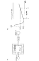
図1に示されるように、鋳造システム10は、相互に直交するXYZの3軸を含む多軸に変位可能なアーム12aを有するロボットからなる搬送装置12と、前記ロボットのアーム12aの先端部に連結されて前記アーム12aと一体的に変位し汲み入れられた溶湯を搬送するラドル(一方の容器)14とを含む。なお、本実施形態では、多軸ロボットによって構成された搬送装置12を例示しているが、例えば、ローダー等を用いてもよい。
As shown in FIG. 1, a
さらに、鋳造システム10は、溶湯が貯留された貯留炉16と、図示しないエアブロー装置及び回転ブラシを含みラドル14の突出口18(後記する図2、図3参照)を清掃する清掃部20と、図示しない複数の金型を開閉する型締め部や溶湯を前記金型内に圧入する射出部とを有するダイカストマシン22とを備える。なお、溶湯は、例えば、アルミニウム又はアルミニウム合金が溶融した流動体からなる。
Further, the
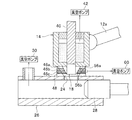
前記射出部には、図2及び図3に示されるように、給湯口24が設けられた円筒状の射出スリーブ(他方の容器)26や、前記射出スリーブ26内を軸方向に沿って摺動することで射出スリーブ26内に供給された溶湯を押圧するプランジャ28等が設けられる。このダイカストマシン22は、貯留炉16と射出部とが分離されたコールドチャンバ式で構成され、射出スリーブ26には、射出スリーブ26内を減圧する真空ポンプ(減圧手段)30が設けられる。
As shown in FIGS. 2 and 3, the injection portion slides along the axial direction in a cylindrical injection sleeve (the other container) 26 provided with a hot
搬送装置12は、貯留炉16と清掃部20とダイカストマシン22(射出スリーブ26)とからなる三者の間に配置され、ロボットのアーム12aの変位によってラドル14が、貯留炉16と清掃部20との間、清掃部20とダイカストマシン22(射出スリーブ26)との間を往復移動可能に設けられている。
The
ラドル14の底部には、外形形状が下端に向かって徐々に縮径するテーパ面32を有する突出口18が設けられ、この突出口18には、ラドル14内の室14aと連通するポート36が設けられる。なお、突出口18は、ラドル本体と一体的に構成し、又はラドル本体と別体で構成された突出口を、例えば、ボルト等で一体的に締結してもよい。
The bottom of the
ラドル14には、ラドル14内の室14aとポート36とを連通させる連通路38を開閉する栓部材40が設けられる。例えば、図示しないアクチュエータを介して栓部材40を所定長だけ上昇させることにより、連通路38が開口してラドル14内の室14aとポート36とが連通する。一方、図示しないアクチュエータを介して栓部材40を所定長だけ下降させることにより、連通路38が閉塞してラドル14内の室14aとポート36との連通が遮断される。
The
さらに、ラドル14の室14a内に汲み入れられた溶湯を真空引きする真空ポンプ(減圧手段)42が、例えば、ロボットのアーム12aに付設される。この真空ポンプ42によってラドル14の室14a内の溶湯を減圧することにより、真空下での給湯が行われる。なお、図1中では、真空ポンプ42を省略している。
Further, a vacuum pump (decompression unit) 42 for evacuating the molten metal pumped into the
貯留炉16からラドル14の室14a内に汲み入れられた溶湯をダイカストマシン22まで搬送し、ラドル14の室14a内の溶湯を溶湯口24から射出スリーブ26内に導入する際、ラドル14の底部に設けられた突出口18と射出スリーブ26の溶湯口24とが接続される。この接続部位には、本発明の実施形態に係るシール構造が適用される。
When the molten metal pumped from the
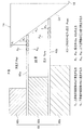
このシール構造は、射出スリーブ26に形成された給湯口24の近傍部位に設けられる。前記シール構造は、中心部に円形状の異径の孔部44a、44bが貫通してそれぞれ形成され、上下方向に所定間隔離間して積層配置された2枚の板状体(シール部材)46a、46bと、前記2枚の板状体46a、46bを支持する支持部材48とを有する。板状体46a、46bの孔部44a、44bには、外形形状がテーパ状に形成されたラドル14の突出口18が嵌挿される。
This seal structure is provided in the vicinity of the hot
上部側の板状体46aは、大径の孔部44aが形成された円板状の鋼材によって弾性変形可能に形成される。下部側の板状体46bは、小径の孔部44bが形成された円板状の鋼材によって弾性変形可能に形成される。2枚の板状体46a、46bの孔部44a、44bの内周縁部45は、図3(d)に示されるように、面取りされた断面R形状に形成され、断面R形状とすることにより、嵌合されるラドル14の突出口18のテーパ面32との間でクリアランスの発生を抑制してシール部が形成される。この2枚の板状体46a、46bは、支持部材48によって弾性変形可能に支持される。
The
支持部材48は、分割された3つの環状ブロック体48a〜48cによって構成され、複数のボルト50によって一体的に締結される。上下方向に隣接する各環状ブロック体48a(48b、48c)の間で2枚の板状体46a、46bが挟持される。最下部の環状ブロック体48aの上面部には、下部側の板状体46bを支持する第1環状段部52aが形成される。下部側の板状体46bの内径部には、最下部の環状ブロック体48aの上面との間でクリアランスを有し弾性変形可能な第1撓み部54aが設けられる。
The
中間の環状ブロック体48bの上面部には、上部側の板状体46aを支持する第2環状段部52bが形成される。上部側の板状体46aの内径部には、中間の環状ブロック体48bの上面との間でクリアランスを有し弾性変形可能な第2撓み部54bが設けられる。
A second
この場合、図3(a)中において、第1撓み部54aにおける径方向の寸法D1と、第2撓み部54bにおける径方向の寸法D2とは、同一に設定されているが(D1=D2)、後記するように、上部側の第2撓み部54bにおける径方向の寸法D2が、下部側の第1撓み部54aにおける径方向の寸法D1よりも短くなるように設定されるとよい(D1>D2)。
In this case, in FIG. 3A, the radial dimension D1 of the
テーパ状に形成されたラドル14の突出口18が2枚の板状体46a、46bの孔部44a、44b内に嵌合されたとき、上下方向に積層された2枚の板状体46a、46bの間に密封された室56が設けられ、中間の環状ブロック体48bに形成された真空ポート58を介して、この室56内のエアを真空引きする真空ポンプ60(減圧手段)が設けられる。
When the projecting
この真空ポンプ60によって室56内のエアを真空引きすることにより、外部から室56内へ進入したエアが、射出スリーブ26内へリークされることを抑制して、シール性能を向上させることができる(図6参照)。この点については、後記で詳細に説明する。
By evacuating the air in the
なお、本実施形態では、2枚の板状体46a、46bの中心に形成された異径の孔部44a、44bによってラドル14の突出口18のテーパ面32の傾斜角度を約45度に設定しているが、これに限定されるものではない。
In the present embodiment, the inclination angle of the tapered
本実施形態に係るシール構造が適用された鋳造システム10は、基本的に以上のように構成されるものであり、次にその動作並びに作用効果について説明する。
The
先ず、図4(a)〜(e)のシステム工程図及び図5のフローチャートに基づいて、鋳造システム10の動作を概略説明する。併せて、適宜、図1〜図3を参照する。また、図6は、2枚の板状体間の室を真空引きする状態を示す説明図である。
First, the operation of the
図4(a)に示されるように、ラドル14の栓部材40を上昇させた状態で貯留炉16内にラドル14を浸漬し、ポート36からラドル14の室14a内に溶湯を汲み入れる(ステップS1)。ラドル14の室14a内に所定量の溶湯が汲み入れられた後、図示しないアクチュエータを駆動させて栓部材40を下降させポート36を閉塞し、ロボットのアーム12aを変位させてラドル14を貯留炉16から引き揚げる。
As shown in FIG. 4A, the
続いて、搬送装置12の支柱を回動中心としてアーム12aを周方向に向かって所定角度だけ回動させ、ラドル14を清掃部20まで移動させる(ステップS2、図1の矢印A参照)。この清掃部20では、ラドル14の突出口18のテーパ面32に付着した溶湯を図示しないエアブロー装置によってエアブローすると共に、図示しない回転ブラシによって除去する(ステップS3、図4(b)参照)。
Subsequently, the
清掃部20においてラドル14のシール部を清掃した後、搬送装置12の支柱を回動中心としてロボットのアーム12aを周方向に向かって所定角度だけ回動させ、ラドル14をダイカストマシン22の射出スリーブ26の給湯口24の上方位置まで移動させる(ステップS4、図1の矢印B参照)。さらに、ロボットのアーム12aを下降させてテーパ面32を有するラドル14の突出口18を、支持部材48によって上下方向に沿って所定距離だけ離間して積層された2枚の板状体46a、46bの孔部44a、44b内に嵌挿する(ステップS5、図4(c)参照)。その際、2枚の板状体46a、46bの第1撓み部54a及び第2撓み部54bは、ラドル15のテーパ面32からの押圧力によって弾性変形した状態でシールする。その際、2枚の板状体46a、46bの第1撓み部54a及び第2撓み部54bが弾性変形することにより、ラドル15の突出口18のテーパ面32を押圧する反力が発生する。なお、この反力については、後記で詳細に説明する。
After cleaning the sealing portion of the
ラドル14のテーパ面32が2枚の板状体46a、46bによってシールされた状態において、各真空ポンプ30、42、60をそれぞれ駆動させ、射出スリーブ26内、溶湯が汲み入れられたラドル14の室14a内、及び、2枚の積層された板状体46a、46b間の室56内が、それぞれ同時に又は略同時に真空引きされる(ステップS6)。この場合、射出スリーブ26内の圧力とラドル14の室14a内の圧力の関係は、射出スリーブ26内の圧力よりもラドル14の室14a内の圧力が高くなる、又は、射出スリーブ26内の圧力とラドル14の室14a内の圧力が同圧となるように設定される。また、射出スリーブ26内の圧力よりも板状体46a、46b間の室56内の圧力が低くなるように設定される。
In a state where the
この場合、図6に示されるように、本実施形態では、上下方向に沿って所定間隔だけ離間して積層された2枚の板状体46a、46bの間の室56が、真空ポンプ60によって真空引きされる。この板状体46a、46b間の室56が真空引きされることにより、大気中から板状体46a、46b間の室56内に進入するエア(図6中の進入エア参照)を吸引して、室56内から射出スリーブ56内へリークされるエア(図6中のスリーブ内リーク参照)のエア量を抑制することができる。
In this case, as shown in FIG. 6, in the present embodiment, a
各真空ポンプ30、42、60によって射出スリーブ26内、溶湯が汲み入れられたラドル14の室14a内、及び、2枚の積層された板状体46a、46b間の室56内が減圧されて、所望の圧力関係に到達したときに図示しないアクチュエータを駆動させてラドル14の栓部材40を上昇させ(ステップS7)、ラドル14の連通路38、ポート36、及び、給湯口24を介して、射出スリーブ26内に溶湯を供給する(図4(d)参照)。
The vacuum pumps 30, 42, 60 depressurize the inside of the
ラドル14の室14a内の溶湯が射出スリーブ26内に供給された後、ロボットのアーム12aの変位によってラドル14を射出スリーブ26から上昇させ、ラドル14の突出口18を2枚の板状体46a、46bの孔部44a、44bから脱抜して離間させる。さらに、ロボットのアーム12aの回動動作によってラドル14をダイカストマシン22の射出スリーブ26から後退させて、ラドル14を清掃部20まで移動させる(ステップS8、図1の矢印C参照)。
After the molten metal in the
清掃部20では、ラドル14の突出口18のポート36、連通路38や栓部材40の先端部に付着した溶湯をエアブローすると共に、回転ブラシによって除去する(ステップS9、図4(e)参照)。
In the
清掃部20による清掃工程が終了した後、ロボットのアーム12aの回動動作によってラドル14を貯留炉16の上方位置まで移動し、次のショットまで待機する(ステップS10、図1の矢印D参照))。
After the cleaning process by the
本実施形態では、ラドル14(一方の容器)の突出口18を、射出スリーブ26(他方の容器)に支持部材48を介して支持された弾性変形可能な2枚の板状体46a、46bの孔部44a、44b内に嵌挿してシールすることにより、前記板状体46a、46bが弾性変形して突出口18のテーパ面32を密着することで、好適にシールすることができる。また、前記板状体46a、46bを鋼材で形成することにより、高温な溶湯に対応する耐熱性を有し、繰り返し使用することができる。
In the present embodiment, the protruding
また、本実施形態では、所定間隔離間して配置された2枚の板状体46a、46b間に形成された室56を、真空ポンプ60によって真空引きすることで、外部から室56内に進入するエアを吸引すると共に、射出スリーブ26側へのリーク(図6中のスリーブ内リーク)を抑制することができる。
Further, in this embodiment, the
さらに、本実施形態では、各真空ポンプ30、60の真空引きにより、射出スリーブ26内の圧力よりも板状体46a、46b間の室56内の圧力が低くなるように設定され、上部側の板状体46の反力が、下部側の板状体46bの反力よりも高くなるように設定されることで、高いシール性能を得ることができる。この点については、後記する。この場合、例えば、上部側の板状体46aの第2撓み部54bの長さD2を、下部側の板状体46bの第1撓み部54aの長さD1よりも短く設定するとよい(D1>D2)。または、上部側の板状体46aの板厚が下部側の板状体46bの板厚と比較して大きくなるように設定されるとよい。
Further, in the present embodiment, the vacuum in each of the
本実施形態では、このようなシール構造を鋳造システム10に適用することで、ラドル14と射出スリーブ26との嵌合部が好適にシールされた状態で、ラドル14内の高温な溶湯を射出スリーブ26内に繰り返し供給することができる。また、真空ポンプ42、30によってラドル14内の溶湯や射出スリーブ26内に供給された溶湯を真空引きすることで、例えば、湯廻り不良やガスによる鋳巣の発生を回避することができる。
In this embodiment, by applying such a sealing structure to the
さらにまた、本実施形態では、2枚の板状体46a、46b間に形成される室56内の圧力が、射出スリーブ26内の圧力よりも低く設定されることにより、シール力を高めてより一層シール性能を向上させることができる。この点については、後記で詳細に説明する。
Furthermore, in the present embodiment, the pressure in the
また、本実施形態では、溶湯が貯留された貯留炉14からラドル14内に溶湯を汲み入れた後、ラドル14を射出スリーブ26まで移動させ、ラドル14の底部に設けられたテーパ状の突出口18を、射出スリーブ26に設けられた弾性変形可能な板状体46a、46bの孔部44a、44bに対し嵌挿してシールする。そして、前記シールが保持された状態で真空引きし、ラドル14内の溶湯を射出スリーブ26内に供給した後、ラドル14を射出スリーブ26から離間させる。このような鋳造方法を採用することで、高品質な鋳造成形品を得ることができる。
Further, in the present embodiment, after the molten metal is pumped into the
次に、2枚の板状体46a、46bに発生する力及び板状体46a、46bの寸法設定について説明する。
結論として、シール部におけるシール性能を向上させるためには、ラドル14の突出口18のテーパ面32と2枚の板状体46a、46b間の室56内で発生する圧力Ppreよりも、射出スリーブ26内のキャビティ圧力Pcaviの圧力が大きいことが好ましい(Ppre<Pcavi)。なお、図7、図8中において、Pairは、大気中の圧力(大気圧)を示している。
Next, the force generated in the two plate-
In conclusion, in order to improve the sealing performance in the sealing portion, the injection sleeve is more than the pressure Ppre generated in the
図7(a)に示されるように、2枚の板状体46a、46b間の室56内で発生する圧力Ppreよりも、射出スリーブ26内のキャビティ圧力Pcaviの圧力が大きい場合(Ppre<Pcavi)、上下空間部の圧力差(Pcavi−Ppre)によって発生する力P2(図9参照)は、上部側の板状体46aではラドル14のテーパ面32から離間する方向に発生し(PA2参照)、下部側の板状体46bでは、ラドル14のテーパ面32側に向かって押圧する方向に発生する。すなわち、下部側の板状体46bに発生する力PBは、PB1、PB2ともに下部側の板状体46bをラドル14のテーパ面32に押圧する方向に発生し、これにより所望の押圧力(シール力)が確保される。
As shown in FIG. 7A, when the pressure of the cavity pressure Pcavi in the
一方、上部側の板状体46aに発生するPAのうち、上下空間部の圧力差によって生じるPA2は、板状体46aを離間させる方向に大きくなるため、所望の押圧力PAを得るためには、PA1が大きくなるように設定する必要がある。
On the other hand, among the P A generated in the upper side of the plate-
これに対して、図7(b)に示されるように、射出スリーブ26内のキャビティ圧力Pcaviよりも、2枚の板状体46a、46b間の室56内で発生する圧力Ppreが大きい場合(Ppre>Pcavi)、上下空間部の圧力差(Ppre−Pcavi)により発生するP2は、上部側の板状体46a及び下部側の板状体46bともに板状体46a、46bをラドル14のテーパ面32から離間させる方向に発生する。以下の各場合に分けて説明する。
Ppre=(Pair−Pcavi)/2の場合
この場合、上部側の板状体46aと下部側の板状体46bにそれぞれ発生するP2は同一となり、P1(板状体の撓み反力)の設定は、前記の場合と同様である。
Ppre>(Pair−Pcavi)/2の場合
この場合、P2(板状体を離間させる方向に作用する力)について、PB2>PA2となり、P1(板状体の撓み反力)は、PB1>PA1となるように設定することが好ましい。
Ppre<(Pair−Pcavi)/2の場合
この場合、P2(板状体を離間させる方向に作用する力)について、PB2<PA2となり、P1(板状体の撓み反力)は、PB1<PA2となるように設定することが好ましい。
In contrast, as shown in FIG. 7B, when the pressure Ppre generated in the
In the case of Ppre = (Pair−Pcavi) / 2 In this case, P 2 generated in the upper plate-
In the case of Ppre> (Pair−Pcavi) / 2 In this case, for P 2 (force acting in the direction of separating the plate-like body), P B2 > P A2 is satisfied, and P 1 (the bending reaction force of the plate-like body) is , P B1 > P A1 is preferably set.
In the case of Ppre <(Pair−Pcavi) / 2 In this case, with respect to P 2 (force acting in the direction of separating the plate-like body), P B2 <P A2 holds, and P 1 (the bending reaction force of the plate-like body) is , P B1 <P A2 is preferably set.
次に、板状体46a、46bの押圧力の設定方法について、以下説明する。
ラドル14の突出口18のテーパ面32に対する、板状体46a、46bの孔部44a、44bの内周縁部45の密着力(シール力)は、板状体46a、46bの板厚、第1撓み部54a及び第2撓み部54bの長さ、板状体46a、46bの材質によって設定される。
また、板状体46a、46bの弾性変形量は、板状体46a、46bの板厚、第1撓み部54a及び第2撓み部54bの長さ、変形量、及び板状体46a、46bの材質によって決定する。
この結果、板状体46a、46bの変形を、塑性変形することを回避して弾性変形内とし繰り返し使用することが可能となる。なお、これらは、例えば、有限要素法のCAEによるシミュレーション解析やテスト治具等によって確認したものである。
Next, a method for setting the pressing force of the plate-
The adhesion force (seal force) of the inner
The elastic deformation amounts of the plate-
As a result, the deformation of the plate-
次に、図9に基づいて、シール部におけるシール力について説明する。
ラドル14の突出口18のテーパ面32に対する、板状体46a、46bの孔部44a、44bの内周縁部45の密着力P(シール力P)は、以下のパラメータにより、P1及びP2を調整することで設定されるとよい。
但し、P1;板状体の撓み反力
P2;上下空間部の圧力差によって発生する力
P;板状体の内周縁部をラドルのテーパ面に密着させる力(シール力)
P=P1−P2
なお、P1∝1/a、v、E、I
(a;撓み部の長さ、v;撓み量、E;ヤング率、I;断面2次モーメント)
P2∝A、ΔP(Pcavi−Ppre、又は、Ppre−Pair)
A;板状体の板面積
Next, the sealing force at the seal portion will be described with reference to FIG.
For the tapered
Where P 1 ; reaction force of bending of the plate-like body P 2 ; force generated by the pressure difference between the upper and lower spaces
P: Force that seals the inner peripheral edge of the plate-like body to the tapered surface of the ladle (seal force)
P = P 1 −P 2
Note that P 1 ∝1 / a, v, E, I
(A: Length of the bending portion, v: Deflection amount, E: Young's modulus, I: Secondary moment of section)
P 2 ∝A, ΔP (Pcavi-Ppre or Ppre-Pair)
A: Plate area of plate
板状体46a、46bの撓み反力P1は、板状体46a、46b及び支持部材48の形状設計によってa(撓み部の長さ)、v(撓み量)を設定し、板状体46a、46bの材質によってE(ヤング率)を設定することが好ましい。
Plate-
また、上下空間部の圧力差によって発生する力P2は、各真空ポンプ30、42、60によって減圧される各空間部の圧力、板状体46a、46b、及び、支持部材48の形状設計によってA(板状体の板面積)を設定することが好ましい。
Further, the force P 2 generated by the pressure difference between the upper and lower space portions depends on the pressure in each space portion reduced by each
なお、シール力Pが矢印Z方向に対してマイナスの値となるとき、板状体46a、46bの内周縁部45とラドル14のテーパ面32との間にクリアランスが発生して、シール構造が成立しない。この結果、板状体46a、46b及び支持部材48の形状設計によって、P=P1−P2>0となることが必要である。
When the sealing force P has a negative value in the direction of the arrow Z, a clearance is generated between the inner
次に、他の実施形態に係るシール構造を図10及び図11に示す。
図2及び図3に示される前記実施形態では、2枚の板状体46a、46bが上下方向に所定間隔離間して積層配置されているが、これに限定されるものではなく、1枚以上の板状体を用いてシール構造とすることが可能である。なお、前記実施形態と同一の構成要素には、同一の参照符号を用い、その詳細な説明を省略する。
Next, a seal structure according to another embodiment is shown in FIGS.
In the embodiment shown in FIGS. 2 and 3, the two plate-
例えば、図10に示されるシール構造では、弾性変形可能な1枚の板状体46で構成されている点に特徴がある。また、図11に示されるシール構造では、弾性変形可能な3枚の板状体46a〜46cを上下方向に所定間隔離間して積層配置している点に特徴がある。この場合、板状体46a〜46c間に形成される2つ室56a、56b内のエアが真空ポンプ60によってそれぞれ真空引きされる。
For example, the seal structure shown in FIG. 10 is characterized in that it is composed of a single plate-
次に、本発明の効果を確認した実施例について説明する。
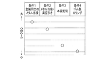
図12(a)に示されるようなテスト治具を創作して、以下のような試験を行った。
テスト治具は、内部にチャンバが形成された容器と、前記チャンバを閉塞するカバー部材と、前記容器とカバー部材との間に配置されてチャンバをシールする各種シール手段と、チャンバ内の圧力を検出する圧力センサと、スイッチとして機能するバルブを介してチャンバ内を減圧する真空ポンプとによって構成される。
Next, examples in which the effects of the present invention have been confirmed will be described.
A test jig as shown in FIG. 12A was created, and the following test was performed.
The test jig includes a container in which a chamber is formed, a cover member that closes the chamber, various sealing means that are disposed between the container and the cover member and seal the chamber, and a pressure in the chamber. It comprises a pressure sensor for detection and a vacuum pump for reducing the pressure in the chamber through a valve that functions as a switch.
試験方法としては、真空ポンプによってチャンバ内を5kPa以下まで真空引きして減圧した後、5〜30kPaまでの復圧時間(t1〜t2)を測定し、この復圧時間にチャンバ体積を乗算してリーク量Qを求めた。なお、図12(b)は、圧力センサによって検出された一つの検出データ例を示したものである。 As a test method, the inside of the chamber is evacuated to 5 kPa or less by a vacuum pump, and then the return pressure time (t1 to t2) from 5 to 30 kPa is measured, and this return pressure time is multiplied by the chamber volume. The leak amount Q was obtained. FIG. 12B shows an example of one detection data detected by the pressure sensor.
各種シール手段としては、条件1;金属同士のメタル当接によるシール、条件2;金属同士のメタル当接によるシール+真空引き、条件3;2枚の板状体+真空引き(本実施形態と同一)、条件4;ゴム製のOリングによるシール、の4つの条件を設定した。 Various sealing means are as follows: condition 1; seal by metal contact between metals, condition 2; seal by metal contact between metals + evacuation, condition 3; two plate-like bodies + evacuation (with this embodiment) The same four conditions were set: the same), condition 4; sealing with a rubber O-ring.
図13に示される試験結果により、本実施例(条件3)では、リーク量を抑制することができ、ゴム製のOリングと略同等のシール能力が得られた。 From the test results shown in FIG. 13, in this example (Condition 3), the amount of leakage could be suppressed, and a sealing ability substantially equivalent to that of a rubber O-ring was obtained.
10 鋳造システム
12 搬送装置
12a アーム
14 ラドル(一方の容器)
14a 室
16 貯留炉
18 突出口
22 ダイカストマシン
26 射出スリーブ(他方の容器)
30、42、60 真空ポンプ(減圧手段)
32 テーパ面
44a、44b 孔部
46、46a〜46c 板状体
54a、54b 撓み部
DESCRIPTION OF
30, 42, 60 Vacuum pump (pressure reduction means)
32
Claims (12)
前記一方の容器には、外形がテーパ状からなる突出口を設け、
前記他方の容器には、前記テーパ状の突出口が嵌合する孔部を有し、鋼材で形成される弾性変形可能な板状体からなるシール部材が設けられ、
前記シール部材は、円板状で所定間隔離間して配置され、支持部材によって弾性変形可能に支持される上部側の板状体と下部側の板状体からなり、
前記上部側の板状体の内径部には、弾性変形可能な第2撓み部が設けられ、
前記下部側の板状体の内径部には、弾性変形可能な第1撓み部が設けられ、
前記第2撓み部における径方向の寸法(D2)は、前記第1撓み部における径方向の寸法(D1)よりも短くなるように設定される(D1>D2)ことを特徴とするシール構造。 A seal structure that seals a fitting portion in which one container and the other container are fitted when the fluid is conveyed in an airtight state from one container to the other container,
The one container is provided with a protruding opening whose outer shape is tapered,
The other container has a hole portion into which the tapered protrusion is fitted , and is provided with a sealing member made of an elastically deformable plate-like body formed of a steel material ,
The sealing member is a disc-like shape and is arranged at a predetermined interval, and is composed of an upper-side plate-like body and a lower-side plate-like body that are supported so as to be elastically deformable by a support member,
On the inner diameter portion of the plate member on the upper side, a second bending portion capable of elastic deformation is provided,
The inner diameter portion of the lower plate-like body is provided with a first flexible portion that can be elastically deformed,
A radial structure (D2) in the second flexible part is set to be shorter than a radial dimension (D1) in the first flexible part (D1> D2) .
前記一方の容器には、外形がテーパ状からなる突出口を設け、
前記他方の容器には、前記テーパ状の突出口が嵌合する孔部を有し、鋼材で形成される弾性変形可能な板状体からなるシール部材が設けられ、
前記シール部材は、円板状で所定間隔離間して配置され、支持部材によって弾性変形可能に支持される上部側の板状体と下部側の板状体からなり、
前記上部側の板状体の板厚は、前記下部側の板状体の板厚と比較して大きく設定されることを特徴とするシール構造。 A seal structure that seals a fitting portion in which one container and the other container are fitted when the fluid is conveyed in an airtight state from one container to the other container,
The one container is provided with a protruding opening whose outer shape is tapered,
The other container has a hole portion into which the tapered protrusion is fitted , and is provided with a sealing member made of an elastically deformable plate-like body formed of a steel material ,
The sealing member is a disc-like shape and is arranged at a predetermined interval, and is composed of an upper-side plate-like body and a lower-side plate-like body that are supported so as to be elastically deformable by a support member,
The thickness of the upper plate member is set to be larger than the plate thickness of the lower plate member.
前記上部側及び前記下部側の板状体間に形成された室を減圧する減圧手段が設けられることを特徴とするシール構造。 The seal structure according to claim 1 or 2,
A seal structure characterized in that a decompression means for decompressing a chamber formed between the plate bodies on the upper side and the lower side is provided.
前記減圧手段は、前記他方の容器内の圧力よりも前記板状体間の室内の圧力が低くなるように設定され、前記上部側の板状体の反力が、前記下部側の板状体の反力よりも高くなるように設定されることを特徴とするシール構造。 The seal structure according to claim 3.
Said pressure reducing means, the pressure in the chamber between the plate-shaped body than the pressure in the other vessel is set to be lower, the reaction force of the upper side of the plate-like body is, the lower side of the plate-like body The seal structure is characterized by being set to be higher than the reaction force of.
前記流動体は、溶湯からなり、
前記一方の容器は、前記溶湯が汲み入れられる可動式のラドルからなり、
前記他方の容器は、ダイカストマシンの射出スリーブからなることを特徴とするシール構造。 The seal structure according to any one of claims 1 to 4,
The fluid consists of a molten metal,
The one container consists ladle moveable which the molten metal is pumped,
The other container is formed of an injection sleeve of a die casting machine.
前記ラドル及び前記射出スリーブには、他の減圧手段がそれぞれ設けられていることを特徴とするシール構造。 The seal structure according to claim 5 ,
The ladle and the injection sleeve are provided with other pressure reducing means, respectively.
前記上部側及び前記下部側の板状体間に形成される室内の圧力は、前記他方の容器内の圧力よりも低く設定されることを特徴とするシール構造。 A seal structure according to claim 3 ,
A seal structure characterized in that the pressure in the chamber formed between the upper and lower plate-like bodies is set lower than the pressure in the other container.
多軸に変位可能なアームを有する搬送装置と、
前記アームに連結されて前記アームと一体的に変位し、前記貯留炉から汲み入れられた溶湯を搬送するラドルと、
前記ラドル内に汲み入れられた溶湯が供給される射出スリーブを有するダイカストマシンと、
を備え、
前記ラドルは、前記搬送装置のアームの変位によって、前記貯留炉と前記射出スリーブとの間を往復移動可能に設けられ、
前記ラドルの底部には、外形形状が下端に向かって徐々に縮径するテーパ面を有する突出口が設けられ、
前記射出スリーブには、前記突出口が嵌合する孔部を有し鋼材で形成される弾性変形可能な板状体からなるシール部材が設けられ、
前記シール部材は、円板状で所定間隔離間して配置され、支持部材によって弾性変形可能に支持される上部側の板状体と下部側の板状体からなり、
前記上部側の板状体の内径部には、弾性変形可能な第2撓み部が設けられ、
前記下部側の板状体の内径部には、弾性変形可能な第1撓み部が設けられ、
前記第2撓み部における径方向の寸法(D2)は、前記第1撓み部における径方向の寸法(D1)よりも短くなるように設定される(D1>D2)ことを特徴とする鋳造システム。 A storage furnace in which molten metal is stored;
A transport device having arms that are displaceable in multiple axes;
A ladle connected to the arm and integrally displaced with the arm to convey the molten metal pumped from the storage furnace;
A die casting machine having an injection sleeve to which molten metal pumped into the ladle is supplied;
With
The ladle is provided so as to be able to reciprocate between the storage furnace and the injection sleeve by the displacement of the arm of the transfer device,
The bottom of the ladle is provided with a protruding opening having a tapered surface whose outer shape gradually decreases in diameter toward the lower end,
The injection sleeve is provided with a seal member made of an elastically deformable plate-like body formed of a steel material having a hole portion into which the protruding port is fitted ,
The sealing member is a disc-like shape and is arranged at a predetermined interval, and is composed of an upper-side plate-like body and a lower-side plate-like body that are supported so as to be elastically deformable by a support member,
On the inner diameter portion of the plate member on the upper side, a second bending portion capable of elastic deformation is provided,
The inner diameter portion of the lower plate-like body is provided with a first flexible portion that can be elastically deformed,
The radial dimension (D2) in the second flexible part is set to be shorter than the radial dimension (D1) in the first flexible part (D1> D2) .
多軸に変位可能なアームを有する搬送装置と、
前記アームに連結されて前記アームと一体的に変位し、前記貯留炉から汲み入れられた溶湯を搬送するラドルと、
前記ラドル内に汲み入れられた溶湯が供給される射出スリーブを有するダイカストマシンと、
を備え、
前記ラドルは、前記搬送装置のアームの変位によって、前記貯留炉と前記射出スリーブとの間を往復移動可能に設けられ、
前記ラドルの底部には、外形形状が下端に向かって徐々に縮径するテーパ面を有する突出口が設けられ、
前記射出スリーブには、前記突出口が嵌合する孔部を有し鋼材で形成される弾性変形可能な板状体からなるシール部材が設けられ、
前記シール部材は、円板状で所定間隔離間して配置され、支持部材によって弾性変形可能に支持される上部側の板状体と下部側の板状体からなり、
前記上部側の板状体の板厚は、前記下部側の板状体の板厚と比較して大きく設定されることを特徴とする鋳造システム。 A storage furnace in which molten metal is stored;
A transport device having arms that are displaceable in multiple axes;
A ladle connected to the arm and integrally displaced with the arm to convey the molten metal pumped from the storage furnace;
A die casting machine having an injection sleeve to which molten metal pumped into the ladle is supplied;
With
The ladle is provided so as to be able to reciprocate between the storage furnace and the injection sleeve by the displacement of the arm of the transfer device,
The bottom of the ladle is provided with a protruding opening having a tapered surface whose outer shape gradually decreases in diameter toward the lower end,
The injection sleeve is provided with a seal member made of an elastically deformable plate-like body formed of a steel material having a hole portion into which the protruding port is fitted ,
The sealing member is a disc-like shape and is arranged at a predetermined interval, and is composed of an upper-side plate-like body and a lower-side plate-like body that are supported so as to be elastically deformable by a support member,
The casting system is characterized in that a plate thickness of the upper plate member is set to be larger than a plate thickness of the lower plate member.
前記上部側及び前記下部側の板状体の間には室が形成され、前記室内を真空引きする減圧手段が設けられることを特徴とする鋳造システム。 A casting system, wherein a chamber is formed between the upper and lower plate-like bodies, and a decompression means for evacuating the chamber is provided.
前記ラドルを射出スリーブまで移動させ、前記ラドルの底部に設けられたテーパ状の突出口を、前記射出スリーブに設けられた弾性変形可能な板状体の孔部に対し嵌挿してシールする工程と、
前記シールが保持された状態で真空引きし、前記ラドル内の溶湯を前記射出スリーブ内に供給する工程と、
前記ラドルを前記射出スリーブから離間させる工程と、
を有し、
前記板状体は、円板状で所定間隔離間して配置され、支持部材によって弾性変形可能に支持される上部側の板状体と下部側の板状体からなり、
前記上部側の板状体の内径部には、弾性変形可能な第2撓み部が設けられ、
前記下部側の板状体の内径部には、弾性変形可能な第1撓み部が設けられ、
前記第2撓み部における径方向の寸法(D2)は、前記第1撓み部における径方向の寸法(D1)よりも短くなるように設定される(D1>D2)ことを特徴とする鋳造方法。 A process of pumping molten metal into a ladle from a storage furnace in which the molten metal is stored;
Moving the ladle to the injection sleeve, and inserting and sealing a taper-like projecting opening provided in the bottom of the ladle into a hole of an elastically deformable plate provided in the injection sleeve; ,
Evacuating in a state where the seal is held, and supplying molten metal in the ladle into the injection sleeve;
Separating the ladle from the injection sleeve;
I have a,
The plate-like body is arranged in a disc-like shape at a predetermined interval and is composed of an upper-side plate-like body and a lower-side plate-like body that are supported by a support member so as to be elastically deformable.
On the inner diameter portion of the plate member on the upper side, a second bending portion capable of elastic deformation is provided,
The inner diameter portion of the lower plate-like body is provided with a first flexible portion that can be elastically deformed,
The radial dimension (D2) in the second flexible part is set to be shorter (D1> D2) than the radial dimension (D1) in the first flexible part (D1> D2) .
前記ラドルを射出スリーブまで移動させ、前記ラドルの底部に設けられたテーパ状の突出口を、前記射出スリーブに設けられた弾性変形可能な板状体の孔部に対し嵌挿してシールする工程と、
前記シールが保持された状態で真空引きし、前記ラドル内の溶湯を前記射出スリーブ内に供給する工程と、
前記ラドルを前記射出スリーブから離間させる工程と、
を有し、
前記板状体は、円板状で所定間隔離間して配置され、支持部材によって弾性変形可能に支持される上部側の板状体と下部側の板状体からなり、
前記上部側の板状体の板厚は、前記下部側の板状体の板厚と比較して大きく設定されることを特徴とする鋳造方法。 A process of pumping molten metal into a ladle from a storage furnace in which the molten metal is stored;
Moving the ladle to the injection sleeve, and inserting and sealing a taper-like projecting opening provided in the bottom of the ladle into a hole of an elastically deformable plate provided in the injection sleeve; ,
Evacuating in a state where the seal is held, and supplying molten metal in the ladle into the injection sleeve;
Separating the ladle from the injection sleeve;
I have a,
The plate-like body is arranged in a disc-like shape at a predetermined interval and is composed of an upper-side plate-like body and a lower-side plate-like body that are supported by a support member so as to be elastically deformable.
The thickness of the plate member on the upper side is set larger than the plate thickness of the plate member on the lower side.
Priority Applications (1)
| Application Number | Priority Date | Filing Date | Title |
|---|---|---|---|
| JP2011231844A JP5770062B2 (en) | 2011-10-21 | 2011-10-21 | Seal structure, sealing method, casting system using the same, and casting method |
Applications Claiming Priority (1)
| Application Number | Priority Date | Filing Date | Title |
|---|---|---|---|
| JP2011231844A JP5770062B2 (en) | 2011-10-21 | 2011-10-21 | Seal structure, sealing method, casting system using the same, and casting method |
Publications (2)
| Publication Number | Publication Date |
|---|---|
| JP2013086169A JP2013086169A (en) | 2013-05-13 |
| JP5770062B2 true JP5770062B2 (en) | 2015-08-26 |
Family
ID=48530640
Family Applications (1)
| Application Number | Title | Priority Date | Filing Date |
|---|---|---|---|
| JP2011231844A Expired - Fee Related JP5770062B2 (en) | 2011-10-21 | 2011-10-21 | Seal structure, sealing method, casting system using the same, and casting method |
Country Status (1)
| Country | Link |
|---|---|
| JP (1) | JP5770062B2 (en) |
Families Citing this family (2)
| Publication number | Priority date | Publication date | Assignee | Title |
|---|---|---|---|---|
| KR102046542B1 (en) * | 2018-02-26 | 2019-11-19 | 주식회사 세진씰 | Centrifugal casting device for the manufacture of floating seal |
| MX2020008373A (en) * | 2018-04-12 | 2020-09-25 | Ahresty Corp | Casting device, method for manufacturing casting, and seal structure. |
Family Cites Families (8)
| Publication number | Priority date | Publication date | Assignee | Title |
|---|---|---|---|---|
| US4146081A (en) * | 1976-08-14 | 1979-03-27 | Walter Reis | Apparatus for die casting |
| JPS61190350U (en) * | 1985-05-20 | 1986-11-27 | ||
| FI112448B (en) * | 2001-05-21 | 2003-12-15 | Jarkko Laine | Casting vessel for molten treatment and casting method |
| JP2003129125A (en) * | 2001-10-15 | 2003-05-08 | Daido Steel Co Ltd | Continuous heat treatment furnace for strip |
| JP3900422B2 (en) * | 2002-08-09 | 2007-04-04 | 晃由 梅村 | Hot water supply method in vacuum die casting method and hot water supply device used therefor |
| JP2007016880A (en) * | 2005-07-07 | 2007-01-25 | Kayaba Ind Co Ltd | Valve structure of pneumatic buffer |
| JP4817339B2 (en) * | 2009-02-17 | 2011-11-16 | 信越化学工業株式会社 | Sealing material for heating furnace |
| JP5605792B2 (en) * | 2010-01-27 | 2014-10-15 | 宇部興産機械株式会社 | Hot water supply apparatus for vacuum casting and hot water supply method |
-
2011
- 2011-10-21 JP JP2011231844A patent/JP5770062B2/en not_active Expired - Fee Related
Also Published As
| Publication number | Publication date |
|---|---|
| JP2013086169A (en) | 2013-05-13 |
Similar Documents
| Publication | Publication Date | Title |
|---|---|---|
| JP2012187754A (en) | Structure and method for clamping built-in component in hollow container | |
| JP6417548B2 (en) | Mold assembly with concentric tubes for hermetically supplying fluid and vacuum | |
| JP5770062B2 (en) | Seal structure, sealing method, casting system using the same, and casting method | |
| EP2758193B1 (en) | Die casting device | |
| TWI361173B (en) | ||
| EP3366446B1 (en) | Wax injection molding machine and injection nozzle used in lost-wax casting | |
| JP2008093719A (en) | Die for blow molding | |
| CA2475024A1 (en) | Method for the production of parts by means of diffusion bonding and superplastic forming, and mold for carrying out said method | |
| US11799178B2 (en) | Liquid injection device | |
| JP2010046876A (en) | Injection molding system and its method | |
| JP6724336B2 (en) | Pneumatic tire vulcanizing apparatus and method | |
| CN204934303U (en) | The high-pressure molding system of sheet metal | |
| JP4394985B2 (en) | Assemblies for the manufacture of hollow mechanical parts by diffusion bonding and superplastic forming, the use of such assemblies and processes for manufacturing such mechanical parts | |
| TWI532543B (en) | Tube hydraulic compound forming system and hydraulic compound forming method | |
| JP2007290306A (en) | Gas injection molding method and apparatus | |
| TWI446401B (en) | Vacuum evacuating head | |
| JP2017517400A (en) | Mold device for forming metal in high vacuum environment | |
| JP2003275858A (en) | Casting apparatus | |
| JP4581502B2 (en) | Casting method and casting apparatus | |
| TWI404583B (en) | A method for diffusion bonding | |
| CN113319185B (en) | Fluid pressure forming device and method for large-diameter thin-wall cylindrical part | |
| KR101298484B1 (en) | Method for Forming Dome and Port of Pressure Vessel Liner | |
| KR102492546B1 (en) | Molding dies with vacuum block | |
| CN116197353A (en) | Device for improving photosensitive resin investment roasting shell expansion for precision casting | |
| JP2010083045A (en) | Mold structure, injection molding apparatus, and molding method |
Legal Events
| Date | Code | Title | Description |
|---|---|---|---|
| A621 | Written request for application examination |
Free format text: JAPANESE INTERMEDIATE CODE: A621 Effective date: 20131127 |
|
| A977 | Report on retrieval |
Free format text: JAPANESE INTERMEDIATE CODE: A971007 Effective date: 20141107 |
|
| A131 | Notification of reasons for refusal |
Free format text: JAPANESE INTERMEDIATE CODE: A131 Effective date: 20141202 |
|
| A521 | Written amendment |
Free format text: JAPANESE INTERMEDIATE CODE: A523 Effective date: 20150130 |
|
| TRDD | Decision of grant or rejection written | ||
| A01 | Written decision to grant a patent or to grant a registration (utility model) |
Free format text: JAPANESE INTERMEDIATE CODE: A01 Effective date: 20150526 |
|
| A61 | First payment of annual fees (during grant procedure) |
Free format text: JAPANESE INTERMEDIATE CODE: A61 Effective date: 20150624 |
|
| R150 | Certificate of patent or registration of utility model |
Ref document number: 5770062 Country of ref document: JP Free format text: JAPANESE INTERMEDIATE CODE: R150 |
|
| LAPS | Cancellation because of no payment of annual fees |