JP5769552B2 - connector - Google Patents
connector Download PDFInfo
- Publication number
- JP5769552B2 JP5769552B2 JP2011187631A JP2011187631A JP5769552B2 JP 5769552 B2 JP5769552 B2 JP 5769552B2 JP 2011187631 A JP2011187631 A JP 2011187631A JP 2011187631 A JP2011187631 A JP 2011187631A JP 5769552 B2 JP5769552 B2 JP 5769552B2
- Authority
- JP
- Japan
- Prior art keywords
- housing
- terminal
- fitting
- housings
- electric wire
- Prior art date
- Legal status (The legal status is an assumption and is not a legal conclusion. Google has not performed a legal analysis and makes no representation as to the accuracy of the status listed.)
- Expired - Fee Related
Links
- 230000013011 mating Effects 0.000 claims description 12
- 230000007246 mechanism Effects 0.000 claims description 12
- 230000008878 coupling Effects 0.000 claims description 8
- 238000010168 coupling process Methods 0.000 claims description 8
- 238000005859 coupling reaction Methods 0.000 claims description 8
- 239000002184 metal Substances 0.000 description 14
- 238000003780 insertion Methods 0.000 description 5
- 230000037431 insertion Effects 0.000 description 5
- 238000005452 bending Methods 0.000 description 4
- 238000000605 extraction Methods 0.000 description 4
- 238000000034 method Methods 0.000 description 3
- 230000008569 process Effects 0.000 description 3
- 239000012212 insulator Substances 0.000 description 2
- 230000000630 rising effect Effects 0.000 description 2
- 230000004308 accommodation Effects 0.000 description 1
- 239000004020 conductor Substances 0.000 description 1
- 238000010586 diagram Methods 0.000 description 1
- 230000006872 improvement Effects 0.000 description 1
- 238000004519 manufacturing process Methods 0.000 description 1
- 230000009466 transformation Effects 0.000 description 1
Images


Landscapes
- Details Of Connecting Devices For Male And Female Coupling (AREA)
- Coupling Device And Connection With Printed Circuit (AREA)
Description
本発明は、第1ハウジングに収容された第1の端子金具の平板状端子接続部と第2ハウジングに収容された第2の端子金具の端子挟持部との接続を、2通りのハウジング嵌合操作から選択することができるコネクタに関する。 According to the present invention, the connection between the flat terminal connection portion of the first terminal fitting housed in the first housing and the terminal clamping portion of the second terminal fitting housed in the second housing is made in two housing fittings. The present invention relates to a connector that can be selected from operations.
図11及び図12は下記特許文献1に開示されたコネクタを示し、図13及び図14は下記特許文献2に開示されたコネクタを示している。 11 and 12 show a connector disclosed in Patent Document 1 below, and FIGS. 13 and 14 show a connector disclosed in Patent Document 2 below.
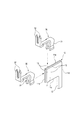
図11に示すように、特許文献1に開示されたコネクタ101は、相手の端子金具に接続される平板状端子接続部111が一端に備えられた第1の端子金具110と、第1の端子金具110を収容保持する第1ハウジング120と、平板状端子接続部111を挟持する端子挟持部131が一端に備えられた第2の端子金具130(図12参照)と、第2の端子金具130を収容保持する第2ハウジング150と、を備えている。
As shown in FIG. 11, the
第2の端子金具130は、図12に示すように、電線140を接続する電線接続部132が、他端に備えられている。
As shown in FIG. 12, the
第2ハウジング150は、図11に示すように、第2の端子金具130に接続された電線140が、ハウジング後端の開口151から後方(図11のX1方向)に延出する。
In the
第1ハウジング120は、回路基板160に搭載されるハウジングである。この第1ハウジング120は、第2ハウジング150における電線140の延出方向と直交する方向(図11の矢印Y1方向)に、第2ハウジング150が嵌合接続される。そのため、第2ハウジング150を収容するハウジング収容空間121が、上方(矢印Y1と逆方向)に開放して形成されている。
The
第1ハウジング120は、ハウジング収容空間121内に平板状端子接続部111が突出するように、第1の端子金具110を保持している。ハウジング収容空間121内に突出する平板状端子接続部111は、相手ハウジングの嵌合方向に向かって起立した状態に保持されていて、第2ハウジング150を矢印Y1方向に嵌合させた際に、平板状端子接続部111が第2の端子金具130の端子挟持部131間に挿入されて挟持される。
The
第1ハウジング120は、ハウジング収容空間121を挟んで対向配置された両側壁122,122の内面部に、ハウジング係止突起123が備えられている。ハウジング係止突起123は、ハウジング相互の嵌合によって端子挟持部131と平板状端子接続部111との接続が完了した時に、第2ハウジング150の両側面に装備された係合部153と係合して、ハウジング相互を結合する。
The
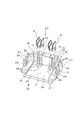
図13に示すように、特許文献2に開示されたコネクタ201は、相手の端子金具に接続される平板状端子接続部111が一端に備えられた第1の端子金具110と、第1の端子金具110を収容保持する第1ハウジング220と、平板状端子接続部111を挟持する端子挟持部231,231が一端に備えられた第2の端子金具230(図14参照)と、第2の端子金具230を収容保持する第2ハウジング250と、を備えている。
As shown in FIG. 13, the
特許文献2のコネクタ201は、第1ハウジング220を図13の矢印Y2方向から第2ハウジング250に嵌合接続する場合、及び第1ハウジング220を図13の矢印X2方向から第2ハウジング250に嵌合接続する場合の2通りで、平板状端子接続部111を端子挟持部231,231に接続できるように、第2の端子金具230や第2ハウジング250の構造を工夫している。
In the
例えば、端子挟持部231,231は、矢印Y2方向及び矢印X2方向の何れから平板状端子接続部111が挿入されても、摺動摩擦等に大きな差異が生じないように、平板状端子接続部111側に凸のコーン形状に成形されている。
For example, the
また、端子挟持部231,231が突出した状態に配置される第2ハウジング250の端子収容空間251は、矢印Y2と対向する側、及び矢印X2と対向する側、の2方を、平板状端子接続部111が挿通可能に開放している。
Further, the
但し、この特許文献2のコネクタ201の場合、ハウジング相互を嵌合接続する際に、ハウジング相互の嵌合を誘導するガイド構造や、嵌合接続が完了した時にハウジング相互を結合するロック手段は、何ら開示されていない。
However, in the case of the
ところで、特許文献1のコネクタ101の場合、ハウジング相互の嵌合接続方向が、電線140の延出方向と直交する方向に限られており、第1ハウジング120の上方(嵌合方向)には、第2ハウジング150を嵌合操作するための作業空間を確保しておく必要がある。言い換えると、特許文献1に開示されたコネクタ101の場合、利用できる配索環境が、固定側である第1ハウジング120の上方に嵌合操作用の作業空間を確保することができる配索環境に限られてしまうという問題があった。
By the way, in the case of the
また、図示はしていないが、従来のコネクタには、電線の延出方向に沿ってハウジング相互を嵌合させる構造のものが多種開発されている。電線の延出方向に沿ってハウジング相互を嵌合させる構造のものは、固定側のハウジングの上方に嵌合操作用の作業空間を確保することができない省スペースの配索環境でも、ハウジング相互の挿抜が可能である。 Although not shown, various types of conventional connectors have been developed in which the housings are fitted together in the extending direction of the electric wires. The structure in which the housings are fitted to each other along the direction in which the wires extend extends, even in a space-saving routing environment in which a working space for the fitting operation cannot be secured above the fixed housing. Insertion and extraction are possible.
しかし、電線の延出方向に沿ってハウジング相互を挿抜する際には、電線に延出方向の撓みが必要になる。従って、電線の延出方向に沿ってハウジング相互を嵌合させる構造のコネクタの場合は、利用できる配索環境が、電線が延出方向に撓み変形可能なように電線の布設経路に余裕を持たせた配索環境に限られてしまうという問題がある。 However, when the housings are inserted and removed along the extending direction of the electric wires, the electric wires need to bend in the extending direction. Therefore, in the case of a connector having a structure in which housings are fitted to each other along the extending direction of the electric wire, the wiring environment that can be used has a margin in the laying path of the electric wire so that the electric wire can be bent and deformed in the extending direction. There is a problem that it is limited to the cabling environment.
即ち、ハウジング相互の挿抜方向が、電線の延出方向又は延出方向と直交する方向の何れか一方に限られているコネクタの場合は、いずれにしても、配索環境が限られてしまうという問題があった。 That is, in the case of a connector in which the housing insertion / extraction direction is limited to either one of the extending direction of the electric wires or the direction orthogonal to the extending direction, the wiring environment is limited in any case. There was a problem.
一方、特許文献2のコネクタ201の場合、電線の延出方向又は延出方向と直交する方向の2方向にハウジング相互の挿抜が可能であるため、上記のような配索環境の制限がなく、配索環境に柔軟に対応することができる。
On the other hand, in the case of the
しかし、ハウジング相互の挿抜を2方向に可能にしたコネクタの場合は、ハウジング相互を嵌合接続する際にハウジング相互の嵌合を誘導するガイド構造や、ハウジング相互の嵌合接続が完了した時にハウジング相互を結合するロック手段を、ハウジング相互の挿抜方向毎に装備する必要があり、ハウジング構造の複雑化を招くため、上記ガイド構造やロック手段の装備が困難になる。実際、特許文献2のコネクタ201では、上記のガイド構造やロック手段については一切開示されていない。上記のガイド構造やロック手段を未装備のコネクタの場合は、嵌合操作時にこじりが発生して挿抜操作が困難になったり、外部からの振動によりハウジング相互の嵌合が緩んで端子金具相互の接触不良を招くおそれがあった。
However, in the case of a connector that allows the housings to be inserted and removed in two directions, a guide structure that guides the fitting of the housings when the housings are fitted and connected, and the housing when the fitting and connecting of the housings are completed. Since it is necessary to equip the locking means for coupling each other in each insertion / extraction direction of the housing, the housing structure becomes complicated, and thus the above guide structure and the locking means are difficult to equip. Actually, the
そこで、本発明の目的は、上記課題を解消することに係り、第1ハウジングに収容された第1の端子金具の平板状端子接続部と第2ハウジングに収容された第2の端子金具の端子挟持部との接続に必要なハウジング相互の嵌合操作が2方向から可能なために、電線の配索環境に柔軟に対応することができ、しかも、端子金具相互の接続が完了した時にハウジング相互を結合状態にロックして、ハウジング相互の嵌合の緩みを防止することができるコネクタを提供することにある。 SUMMARY OF THE INVENTION Accordingly, an object of the present invention is to solve the above-described problems, and a flat terminal connection portion of a first terminal fitting housed in the first housing and a terminal of the second terminal fitting housed in the second housing. Since the housing can be fitted in two directions, which is necessary for the connection with the clamping part, it is possible to flexibly cope with the cable routing environment, and when the connection between the terminal fittings is completed, the housings It is an object of the present invention to provide a connector that can be locked in a coupled state to prevent loose fitting of housings.
本発明の前述した目的は、下記の構成により達成される。
(1) 相手の端子金具に接続される平板状端子接続部が一端に備えられた第1の端子金具と、
相手ハウジングの嵌合方向に向かって前記平板状端子接続部が突出するように前記第1の端子金具を収容保持する第1ハウジングと、
前記平板状端子接続部を挟持する端子挟持部が一端に備えられると共に電線を接続する電線接続部が他端に備えられた第2の端子金具と、
前記第1ハウジングと接続した際に前記平板状端子接続部が前記端子挟持部に挿入されて挟持されるように、前記第2の端子金具を収容保持する第2ハウジングと、
を備えるコネクタであって、
前記第1ハウジング及び第2ハウジングの内の一方のハウジングに突設された嵌合ガイド突起と、
前記第2ハウジングから延出する前記電線の延出方向に沿って前記第1ハウジングと第2ハウジングとを突き合わせた時に、前記嵌合ガイド突起を電線の延出方向に沿って誘導して前記平板状端子接続部と端子挟持部とを接続状態に導くように他方のハウジングに装備された第1ガイド溝と、
前記第2ハウジングから延出する前記電線の延出方向と直交する方向に沿って前記第1ハウジングと第2ハウジングとを突き合わせた時に、前記嵌合ガイド突起を前記電線の延出方向と直交する方向に誘導して前記平板状端子接続部と端子挟持部とを接続状態に導くように他方のハウジングに装備された第2ガイド溝と、
ハウジング相互の突き合わせによって前記平板状端子接続部と端子挟持部との接続が完了した時にハウジング相互の結合状態をロックするハウジングロック機構と、
を備えることを特徴とするコネクタ。
The above-described object of the present invention is achieved by the following configuration.
(1) a first terminal fitting provided at one end with a flat terminal connecting portion connected to a mating terminal fitting;
A first housing that accommodates and holds the first terminal fitting so that the flat terminal connection portion protrudes in the mating direction of the mating housing;
A second terminal fitting provided with a terminal holding part for holding the flat plate terminal connecting part at one end and a wire connecting part for connecting an electric wire at the other end;
A second housing that accommodates and holds the second terminal fitting so that the flat terminal connecting portion is inserted into the terminal clamping portion when being connected to the first housing;
A connector comprising:
A fitting guide protrusion protruding from one of the first housing and the second housing;
When the first housing and the second housing are abutted along the extending direction of the electric wire extending from the second housing, the fitting guide protrusion is guided along the extending direction of the electric wire, and the flat plate A first guide groove provided on the other housing so as to guide the terminal-like terminal connecting portion and the terminal clamping portion to a connected state;
When the first housing and the second housing are brought into contact with each other along a direction orthogonal to the extending direction of the electric wire extending from the second housing, the fitting guide protrusion is orthogonal to the extending direction of the electric wire. A second guide groove provided in the other housing so as to guide the plate-like terminal connecting portion and the terminal clamping portion to a connected state by guiding in a direction;
A housing locking mechanism that locks the coupling state between the housings when the connection between the flat-plate terminal connecting portion and the terminal clamping portion is completed by abutting the housings;
A connector comprising:
(2)前記端子挟持部は、前記端子挟持部と前記電線接続部との間を繋いでいる細幅帯状板の端部の両側に延出する一対の舌状片を、前記平板状端子接続部を挟む間隔で対向するように折り曲げることで形成されていることを特徴とする上記(1)に記載のコネクタ。 (2) The terminal pinching portion is formed by connecting a pair of tongue-like pieces extending on both sides of an end portion of a narrow strip plate connecting the terminal pinching portion and the wire connection portion to the flat plate terminal connection. The connector according to (1), wherein the connector is formed by being bent so as to face each other with an interval between the portions.
上記(1)の構成によれば、第1ハウジングに収容された第1の端子金具の平板状端子接続部と第2ハウジングに収容された第2の端子金具の端子挟持部との接続に必要なハウジング相互の嵌合操作が、電線の延出方向に沿う第1の方向、或いは電線の延出方向と直交する第2の方向の2方向から可能である。そのため、例えば、第1ハウジングの上方に嵌合操作用の作業空間が確保することができない配索環境に設置する場合には、電線の延出方向に沿う第1の方向からのハウジング相互の突き合わせによりハウジング相互を嵌合接続させ、電線に延出方向の撓みを確保することができないような配索環境に設置する場合には、電線の延出方向と直交する第2の方向からのハウジング相互の突き合わせによりハウジング相互を嵌合接続させることができ、電線の配索環境に柔軟に対応することができる。 According to the configuration of (1) above, it is necessary for the connection between the flat terminal connection portion of the first terminal fitting housed in the first housing and the terminal clamping portion of the second terminal fitting housed in the second housing. The fitting operation between the housings can be performed from two directions: a first direction along the extending direction of the electric wires, or a second direction orthogonal to the extending direction of the electric wires. Therefore, for example, when installing in a routing environment in which a working space for fitting operation cannot be secured above the first housing, the housings face each other from the first direction along the extending direction of the wires. When installing in a routing environment where the housings can be fitted and connected with each other and bending in the extending direction cannot be secured to the electric wires, the housings from the second direction orthogonal to the extending direction of the electric wires Thus, the housings can be fitted and connected to each other to flexibly cope with the wiring environment.
また、何れの方向からハウジング相互を突き合わせる場合でも、一方のハウジングに突設された嵌合ガイド突起が、他方のハウジングに装備された第1ガイド溝又は第2ガイド溝の何れかによって誘導されて、第1の端子金具の平板状端子接続部と第2の端子金具の端子挟持部とが接続された状態に導かれる。言い換えれば、ハウジング相互の突き合わせ操作時には、一方のハウジングに突設された嵌合ガイド突起が他方のハウジングに装備された第1ガイド溝又は第2ガイド溝の何れかに係合して、突き合わせ方向へ誘導されるため、ハウジング相互の嵌合操作時にこじりの発生を防止することができる。従って、ハウジング相互の挿抜操作を容易にすることができる。 In addition, in the case where the housings are abutted with each other from any direction, the fitting guide protrusion protruding from one housing is guided by either the first guide groove or the second guide groove provided on the other housing. Thus, the flat terminal connection portion of the first terminal fitting and the terminal clamping portion of the second terminal fitting are led to a connected state. In other words, during the abutting operation between the housings, the fitting guide protrusions protruding from one housing are engaged with either the first guide groove or the second guide groove provided on the other housing, and the abutting direction Therefore, it is possible to prevent twisting during the fitting operation between the housings. Therefore, the housing can be easily inserted and removed.
また、ハウジング相互の突き合わせにより端子金具相互の接続が完了した時には、ハウジングロック機構によりハウジング相互の結合状態がロックされる。そのため、外部からの振動によりハウジング相互の嵌合が緩むことを防止することができる。従って、ハウジング相互の嵌合の緩みによって端子金具相互の接触不良が発生することを防止することができる。 Further, when the connection of the terminal fittings is completed by the butting of the housings, the coupling state of the housings is locked by the housing lock mechanism. Therefore, it is possible to prevent loosening of the fitting between the housings due to vibration from the outside. Therefore, it is possible to prevent a contact failure between the terminal fittings due to loose fitting between the housings.
上記(2)の構成によれば、第2の端子金具の端子挟持部は、該端子挟持部と電線接続部との間を繋いでいる細幅帯状板の端部の両側に延出する一対の舌状片を、前記平板状端子接続部を挟む間隔で対向するように折り曲げることで形成されたもので、構造が単純である。そのため、第2の端子金具の構造の単純化により、第2の端子金具の生産性を向上させることができる。 According to the configuration of (2) above, the terminal pinching portion of the second terminal fitting is a pair that extends to both sides of the end of the narrow strip plate connecting the terminal pinching portion and the wire connection portion. The tongue-shaped piece is bent so as to be opposed to each other at an interval between which the flat-plate terminal connecting portion is sandwiched, and the structure is simple. Therefore, the productivity of the second terminal fitting can be improved by simplifying the structure of the second terminal fitting.
本発明によるコネクタによれば、それぞれのハウジングに収容保持されている端子金具相互の接続に必要なハウジング相互の嵌合操作が、電線の延出方向に沿う第1の方向、或いは電線の延出方向と直交する第2の方向の2方向から可能である。そのため、配索環境に応じてハウジング相互の嵌合操作を選択することができ、電線の配索環境に柔軟に対応することができる。 According to the connector of the present invention, the fitting operation between the housings necessary for the connection between the terminal fittings accommodated and held in the respective housings is the first direction along the extending direction of the electric wires, or the extending of the electric wires. It is possible from two directions, a second direction orthogonal to the direction. Therefore, the fitting operation between the housings can be selected according to the wiring environment, and the wiring environment of the electric wire can be flexibly dealt with.
また、何れの方向からハウジング相互を突き合わせる場合でも、一方のハウジングに突設された嵌合ガイド突起が、他方のハウジングに装備された第1ガイド溝又は第2ガイド溝の何れかによって誘導される。そのため、ハウジング相互の嵌合操作時にこじりの発生を防止することができる。従って、ハウジング相互の挿抜操作を容易にすることができる。 In addition, in the case where the housings are abutted with each other from any direction, the fitting guide protrusion protruding from one housing is guided by either the first guide groove or the second guide groove provided on the other housing. The Therefore, it is possible to prevent the occurrence of a twist during the fitting operation between the housings. Therefore, the housing can be easily inserted and removed.
また、ハウジング相互の突き合わせにより端子金具相互の接続が完了した時には、ハウジングロック機構によりハウジング相互の結合状態がロックされる。そのため、外部からの振動によりハウジング相互の嵌合が緩むことを防止することができる。従って、ハウジング相互の嵌合の緩みによって端子金具相互の接触不良が発生することを防止することができる。 Further, when the connection of the terminal fittings is completed by the butting of the housings, the coupling state of the housings is locked by the housing lock mechanism. Therefore, it is possible to prevent loosening of the fitting between the housings due to vibration from the outside. Therefore, it is possible to prevent a contact failure between the terminal fittings due to loose fitting between the housings.
以下、本発明に係るコネクタの好適な実施形態について、図面を参照して詳細に説明する。 DESCRIPTION OF EMBODIMENTS Hereinafter, preferred embodiments of a connector according to the present invention will be described in detail with reference to the drawings.
図1〜図10は本発明に係るコネクタの一実施形態の説明図で、図1は本発明に係るコネクタの一実施形態のハウジング相互を嵌合接続することができる2通りの嵌合操作の説明図、図2は図1に示した第1の端子金具と、該第1の端子金具に接続される第2の端子金具の拡大斜視図、図3は図1に示した第1の端子金具と第1ハウジングの分解斜視図、図4は図2に示した第2の端子金具の説明図で、図4(a)は端子全体の斜視図、図4(b)は電線接続部として端子金具に装備された圧接刃の拡大図、図4(c)は端子金具の一端に装備された端子挟持部の拡大斜視図である。また、図5は図1に示した第2ハウジングの分解斜視図、図6は図5に示した第2ハウジングのハウジング本体への第2の端子金具の取り付け構造を示す斜視図、図7は図5に示した第2ハウジングにリボン電線を接続する工程の説明図、図8は図7(c)に示した第2ハウジングにおけるC部(ロックアーム)の拡大図、図9は図7(c)に示した第2ハウジングのD矢視図、図10は図9のE−E断面図である。 FIGS. 1-10 is explanatory drawing of one Embodiment of the connector based on this invention, FIG. 1 is two types of fitting operation which can carry out fitting connection of the housing of one Embodiment of the connector based on this invention. FIG. 2 is an explanatory view, FIG. 2 is an enlarged perspective view of the first terminal fitting shown in FIG. 1 and a second terminal fitting connected to the first terminal fitting, and FIG. 3 is the first terminal shown in FIG. 4 is an exploded perspective view of the metal fitting and the first housing, FIG. 4 is an explanatory view of the second terminal metal fitting shown in FIG. 2, FIG. 4A is a perspective view of the entire terminal, and FIG. FIG. 4C is an enlarged perspective view of a terminal clamping portion provided at one end of the terminal fitting. 5 is an exploded perspective view of the second housing shown in FIG. 1, FIG. 6 is a perspective view showing a structure for attaching the second terminal fitting to the housing body of the second housing shown in FIG. 5, and FIG. FIG. 8 is an explanatory view of a process of connecting a ribbon electric wire to the second housing shown in FIG. 5, FIG. 8 is an enlarged view of a portion C (lock arm) in the second housing shown in FIG. 7C, and FIG. FIG. 10 is a cross-sectional view taken along the line E-E in FIG. 9.
この一実施形態のコネクタ1は、第1の端子金具10と、複数の第1の端子金具10を収容保持する第1ハウジング20と、第2の端子金具30(図2参照)と、複数の第2の端子金具30を収容保持する第2ハウジング40と、を備える。
The connector 1 according to this embodiment includes a first terminal fitting 10, a
第1の端子金具10は、図2に示すように、相手の端子金具に接続される平板状端子接続部11が一端に備えられ、且つ、他端には回路基板の導体に接続されるリード部12が備えられている。
As shown in FIG. 2, the first terminal fitting 10 is provided with a flat
平板状端子接続部11は、矩形の平板状で、上縁11aと該上縁11aに直交する前縁11bの2辺には、後述する第2の端子金具30の端子挟持部31への挿入を容易にするための面取り13が設けられている。
The flat
第1ハウジング20は、相手ハウジングである第2ハウジング40が突き合わせられるハウジング収容空間21を有している。ハウジング収容空間21は、底壁部21aと、該底壁部21aの両側に立ち上がる左右の側壁部21bと、底壁部21aの後縁から立ち上がる後部壁21cとで、上方及び前方を開放した空間に形成されている。
The
本実施形態の第1ハウジング20の場合、底壁部21aの表面211と、後部壁21cの内面212とは、後述する第2ハウジング40との突き合わせ面となる。また、図3において、底壁部21aの表面211と直交する矢印Y3方向と、後部壁21cの内面212と直交する矢印X3方向と、の2方向が、後述する第2ハウジング40の嵌合方向となる。
In the case of the
第1ハウジング20の底壁部21a及び後部壁21cには、第1の端子金具10を収容保持する複数の端子保持溝23a,23cが装備されている。
The
底壁部21aに形成された端子保持溝23aは、平板状端子接続部11の下縁11cを収容保持する。後部壁21cに形成された端子保持溝23cは、平板状端子接続部11の後縁11dとリード部12とを収容保持する。
The
端子保持溝23a及び端子保持溝23cは、図3の矢印Y3方向に沿って第1の端子金具10を挿入することで、平板状端子接続部11が嵌合方向(矢印X3方向及び矢印Y3方向)に向かってハウジング収容空間21に突出するように、第1の端子金具10を支持する。
The
端子保持溝23a及び端子保持溝23cにおいて、リード部12が挿通する部分は、底壁部21aの下面側に貫通している。第1の端子金具10のリード部12の先端(図2では下端)は、底壁部21aを挿通して、底壁部21aの下面側に突出した状態に支持される。
In the
一実施形態の第1ハウジング20は、第1ハウジング20の幅方向に所定の間隔を開けて、6個の第1の端子金具10を支持する。各第1の端子金具10を支持する端子保持溝23a,23cは、隣接する第1の端子金具10相互が平面視で千鳥状の配置となるように、形成されている。
The
本実施形態の第1ハウジング20には、第1ガイド溝25と、第2ガイド溝26と、ロック用係止穴27と、が備えられている。
The
第1ガイド溝25は、第2ハウジング40から延出するリボン電線50の延出方向に沿って延在する溝で、図3に示すように、第1ハウジング20の底壁部21aの両側部に、装備されている。この第1ガイド溝25は、図1の領域R1において矢印Bで示すように、リボン電線50の延出方向(図1の矢印X4方向)に沿って第1ハウジング20と第2ハウジング40とを突き合わせた時に、後述の嵌合ガイド突起45をリボン電線50の延出方向に沿って誘導して、平板状端子接続部11と端子挟持部31とを接続状態に導く。
The
第2ガイド溝26は、第2ハウジング40から延出するリボン電線50の延出方向と直交する方向に沿って延在する溝で、図3に示すように、第1ハウジング20の後部壁21cの両側部に、装備されている。この第2ガイド溝26は、図1の領域R2において矢印Aで示すように、リボン電線50の延出方向と直交する方向に沿って第1ハウジング20と第2ハウジング40とを突き合わせた時に、後述の嵌合ガイド突起45をリボン電線50の延出方向と直交する方向に誘導して、平板状端子接続部11と端子挟持部31とを接続状態に導く。
The
ロック用係止穴27は、図3に示すように、第1ハウジング20の両側壁部21bに装備されている。このロック用係止穴27は、ハウジング相互の突き合わせによって平板状端子接続部11と端子挟持部31との接続が完了した時に、後述の第2ハウジング40上のロック突起46bと係合して、ハウジング相互の結合状態をロックする。
As shown in FIG. 3, the
ロック用係止穴27が装備された側壁部21bの前縁及び上縁には、後述の第2ハウジング40上のロック突起46bを側壁部21bの内側に入り易くするための面取り215が形成されている。
A
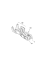
第2の端子金具30は、図4に示すように、平板状端子接続部11を挟持する端子挟持部31が一端に備えられると共に、リボン電線50を圧接接続する電線接続部としての一対の圧接刃32,32が他端に備えられている。
As shown in FIG. 4, the second terminal fitting 30 is provided with a
本実施形態の第2の端子金具30は、端子挟持部31と一対の圧接刃32,32との間は、リボン電線50の延出方向に沿って延在する細幅帯状板33が繋いでいる。細幅帯状板33は、図4(a)に示すように、端子挟持部31や一対の圧接刃32,32の部位と比較すると幅寸法が小さい帯状である。
In the second terminal fitting 30 of the present embodiment, a
端子挟持部31は、リボン電線50の延出方向に沿って第2の端子金具30の一端寄りに延在する細幅帯状板33の端部の両側に延出する一対の舌状片31aを、平板状端子接続部11を挟む間隔で対向するように折り曲げることで形成されている。
The
端子挟持部31は、先端側に、幅を拡げる方向に曲げられた曲げ部31bを有している。曲げ部31bは、リボン電線50の延出方向と直交する方向にハウジング相互を嵌合接続させた時に、端子挟持部31間に平板状端子接続部11を入り易くする。
The
また、本実施形態の端子挟持部31は、リボン電線50の延出方向に沿ってハウジング相互を嵌合接続させた時に、最初に平板状端子接続部11の前縁11bに当たる先端側の角部に、図4(c)に示すように、面取り313を備えている。この面取り313は、一対の舌状片31a,31a間に平板状端子接続部11を挿入し易くする。
Moreover, the
電線接続部として装備された圧接刃32は、図4(b)に示すように、先端側が3角形状に尖っている。また、図4(b)に示すように、一対の圧接刃32の互いに対向する内縁側の角部には、リボン電線50の被覆を切断し易くするために肉厚を薄くしたテーパ面32aが形成されている。
As shown in FIG. 4B, the
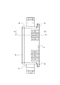
第2ハウジング40は、図5〜図7に示すように、複数の第2の端子金具30と該第2の端子金具30に接続されるリボン電線50とを収容するハウジング本体41と、ハウジング本体41に収容された第2の端子金具30及びリボン電線50をハウジング本体41の底壁41aに押圧固定するカバー43と、を備える。
As shown in FIGS. 5 to 7, the
ハウジング本体41の底壁41aには、図6に示すように、複数の第2の端子金具30を位置決めする複数の端子嵌合凹部411と、リボン電線50を位置決めする電線位置決め突起412とが設けられている。
The
端子嵌合凹部411は、図7(a)に示すように、第2の端子金具30を、圧接刃32がカバー43側に向いた姿勢に位置決めする。また、複数の端子嵌合凹部411は、図6に示すように、隣接する第2の端子金具30相互が千鳥状に並ぶように、設けられている。千鳥状の配置では、第2の端子金具30の細幅帯状板33に、隣接する第2の端子金具30の圧接刃32の部位が並ぶように、配置が工夫されている。このような千鳥状配置にすることにより、複数の第2の端子金具30を狭ピッチで実装することが可能になる。
As shown in FIG. 7A, the terminal
ハウジング本体41に収容されるリボン電線50は、図7に示すように、幅方向の中央に、幅広の絶縁体部52が装備されている。この絶縁体部52には、ハウジング本体41の底壁41aに装備した電線位置決め突起412に嵌合する位置決め穴521が貫通形成されている。リボン電線50は、図7(a)に示すように、位置決め穴521を電線位置決め突起412に嵌合させることで、底壁41a上に位置決めされ、構成している電線53の端部が、第2の端子金具30の一対の圧接刃32,32に圧接可能な位置に位置決めされる。
As shown in FIG. 7, the ribbon
ハウジング本体41に装着されたリボン電線50や第2の端子金具30は、図10に示すように、ハウジング本体41の上に装着されるカバー43によって底壁41aに押圧固定される。底壁41aに押圧固定された第2の端子金具30の端子挟持部31は、図10に示すように、底壁41aの外側に突出する。端子挟持部31が突出する位置は、第1ハウジング20上のハウジング収容空間21における第1の端子金具10の位置に対応している。
The ribbon
即ち、ハウジング本体41は、第1ハウジング20と接続した際に平板状端子接続部11が端子挟持部31に挿入されて挟持されるように、第2の端子金具30を収容保持する。
That is, the
以上に説明したハウジング本体41は、一対の嵌合ガイド突起45と、一対のロックアーム46と、を備えている。
The housing
一対の嵌合ガイド突起45は、図5に示すように、ハウジング本体41の前端側両側面に突設されている。この嵌合ガイド突起45は、図1の領域R1に示すようにリボン電線50の延出する方向に沿ってハウジング相互を突き合わせる際には、第1ハウジング20の第1ガイド溝25に、突き合わせ方向に沿って摺動可能に嵌合する。また、嵌合ガイド突起45は、図1の領域R2に示すようにリボン電線50の延出する方向と直交する方向に沿ってハウジング相互を突き合わせる際には、第1ハウジング20の第2ガイド溝26に、突き合わせ方向に沿って摺動可能に嵌合する。
As shown in FIG. 5, the pair of
ロックアーム46は、ハウジング本体41の両外側面に装備されている。このロックアーム46は、第1ハウジング20の両側壁部21bに形成されたロック用係止穴27との協働で、ハウジングロック機構を構成する。
The
ハウジングロック機構は、ハウジング相互の突き合わせによって平板状端子接続部11と端子挟持部31との接続が完了した時に、ハウジング相互の結合状態をロックする機構である。
The housing locking mechanism is a mechanism that locks the coupling state between the housings when the connection between the flat
ロックアーム46は、図5及び図6に示すように、一端がハウジング本体41の外側面の前端寄りに接合し、他端がハウジング本体41の外側面の後端寄りに接合した両持ち梁構造の弾性アーム46aと、弾性アーム46aの中間部に突設されて第1ハウジング20のロック用係止穴27に係合可能なロック突起46bと、を備えている。
As shown in FIGS. 5 and 6, the
ロック突起46bは、図8に示すように、前端面461と下面462が、テーパ面になっている。
As shown in FIG. 8, the
ロック突起46bの前端面461は、図1の領域R1に示すようにリボン電線50の延出する方向に沿ってハウジング相互を突き合わせる際に、最初に第1ハウジング20の側壁部21bの前縁の面取り215(図3参照)に当接する部分で、弾性アーム46aの撓み変形を容易にする。
The
ロック突起46bの下面462は、図1の領域R2に示すようにリボン電線50の延出する方向と直交する方向に沿ってハウジング相互を突き合わせる際に、最初に第1ハウジング20の側壁部21bの上縁の面取り215(図3参照)に当接する部分で、弾性アーム46aの撓み変形を容易にする。
The
ロックアーム46は、ハウジング相互の突き合わせによって平板状端子接続部11と端子挟持部31との接続が完了した時に、ロック突起46bが第1ハウジング20のロック用係止穴27に係合することで、ハウジング相互の結合状態をロックする。
The
以上に説明した一実施形態のコネクタ1では、第1ハウジング20に収容された第1の端子金具10の平板状端子接続部11と第2ハウジング40に収容された第2の端子金具30の端子挟持部31との接続に必要なハウジング相互の嵌合操作が、図1に示したように、リボン電線50の延出方向に沿う第1の方向、或いはリボン電線50の延出方向と直交する第2の方向の2方向から可能である。
In the connector 1 of the embodiment described above, the flat
そのため、例えば、第1ハウジング20の上方に嵌合操作用の作業空間が確保することができない配索環境に設置する場合には、リボン電線50の延出方向に沿う第1の方向からのハウジング相互の突き合わせによりハウジング相互を嵌合接続させ、リボン電線50に延出方向の撓みを確保することができないような配索環境に設置する場合には、リボン電線50の延出方向と直交する第2の方向からのハウジング相互の突き合わせによりハウジング相互を嵌合接続させることができ、リボン電線50の配索環境に柔軟に対応することができる。
Therefore, for example, when installing in a routing environment where a working space for fitting operation cannot be secured above the
また、何れの方向からハウジング相互を突き合わせる場合でも、第2ハウジング40に突設された嵌合ガイド突起45が、第1ハウジング20に装備された第1ガイド溝25又は第2ガイド溝26の何れかによって誘導されて、第1の端子金具10の平板状端子接続部11と第2の端子金具30の端子挟持部31とが接続された状態に導かれる。言い換えれば、ハウジング相互の突き合わせ操作時には、第2ハウジング40に突設された嵌合ガイド突起45が第1ハウジング20に装備された第1ガイド溝25又は第2ガイド溝26の何れかに係合して、突き合わせ方向へ誘導されるため、ハウジング相互の嵌合操作時にこじりの発生を防止することができる。従って、ハウジング相互の挿抜操作を容易にすることができる。
Further, even when the housings are abutted with each other from any direction, the
また、ハウジング相互の突き合わせにより端子金具相互の接続が完了した時には、第1ハウジング20上のロック用係止穴27と第2ハウジング40上のロックアーム46とで構成されるハウジングロック機構により、ハウジング相互の結合状態がロックされる。そのため、外部からの振動によりハウジング相互の嵌合が緩むことを防止することができる。従って、ハウジング相互の嵌合の緩みによって端子金具相互の接触不良が発生することを防止することができる。
Further, when the connection between the terminal fittings is completed by the butting of the housings, the housing locking mechanism configured by the locking
また、以上に説明した一実施形態のコネクタ1では、第2の端子金具30の端子挟持部31は、端子挟持部31と電線接続部である一対の圧接刃32,32との間を繋いでいる細幅帯状板33の端部の両側に延出する一対の舌状片31aを、平板状端子接続部11を挟む間隔で対向するように折り曲げることで形成されたもので、図12や図14に示した端子金具と比較して、構造が著しく単純である。そのため、第2の端子金具30の構造の単純化により、第2の端子金具30の生産性を向上させることができる。
Moreover, in the connector 1 of one Embodiment demonstrated above, the
なお、本発明のコネクタは、前述した実施形態に限定されるものでなく、適宜、変形、改良等が可能である。 In addition, the connector of this invention is not limited to embodiment mentioned above, A deformation | transformation, improvement, etc. are possible suitably.
例えば、嵌合ガイド突起45を装備するハウジングは、第2ハウジング40に限るものではなく、第1ハウジング20の内側面に装備するようにしても良い。その場合に、第1ハウジング20に装備された嵌合ガイド突起45の配置に対応して、第2ハウジング40の外側面に、第1ガイド溝25や第2ガイド溝26を形成することになる。
For example, the housing provided with the
また、上記実施形態においてハウジングロック機構を構成しているロックアームやロック用係止穴の配置や形状も、本発明の目的を達成できるものであれば、任意であり、前述した実施形態に限定されない。 In addition, the arrangement and shape of the lock arm and the locking hole forming the housing lock mechanism in the above embodiment are arbitrary as long as the object of the present invention can be achieved, and is limited to the above-described embodiment. Not.
1 コネクタ
10 第1の端子金具
11 平板状端子接続部
20 第1ハウジング
25 第1ガイド溝
26 第2ガイド溝
27 ロック用係止穴(ハウジングロック機構)
30 第2の端子金具
31 端子挟持部
31a 舌状片
40 第2ハウジング
45 嵌合ガイド突起
46 ロックアーム(ハウジングロック機構)
46b ロック突起(ハウジングロック機構)
50 リボン電線(電線)
DESCRIPTION OF SYMBOLS 1
30 Second terminal fitting 31
46b Lock protrusion (Housing lock mechanism)
50 Ribbon wire (wire)
Claims (2)
相手ハウジングの嵌合方向に向かって前記平板状端子接続部が突出するように前記第1の端子金具を収容保持する第1ハウジングと、
前記平板状端子接続部を挟持する端子挟持部が一端に備えられると共に電線を接続する電線接続部が他端に備えられた第2の端子金具と、
前記第1ハウジングと接続した際に前記平板状端子接続部が前記端子挟持部に挿入されて挟持されるように、前記第2の端子金具を収容保持する第2ハウジングと、
を備えるコネクタであって、
前記第1ハウジング及び第2ハウジングの内の一方のハウジングに突設された嵌合ガイド突起と、
前記第2ハウジングから延出する前記電線の延出方向に沿って前記第1ハウジングと第2ハウジングとを突き合わせた時に、前記嵌合ガイド突起を電線の延出方向に沿って誘導して前記平板状端子接続部と端子挟持部とを接続状態に導くように他方のハウジングに装備された第1ガイド溝と、
前記第2ハウジングから延出する前記電線の延出方向と直交する方向に沿って前記第1ハウジングと第2ハウジングとを突き合わせた時に、前記嵌合ガイド突起を前記電線の延出方向と直交する方向に誘導して前記平板状端子接続部と端子挟持部とを接続状態に導くように他方のハウジングに装備された第2ガイド溝と、
ハウジング相互の突き合わせによって前記平板状端子接続部と端子挟持部との接続が完了した時にハウジング相互の結合状態をロックするハウジングロック機構と、
を備えることを特徴とするコネクタ。 A first terminal fitting provided at one end with a flat terminal connecting portion connected to a mating terminal fitting;
A first housing that accommodates and holds the first terminal fitting so that the flat terminal connection portion protrudes in the mating direction of the mating housing;
A second terminal fitting provided with a terminal holding part for holding the flat plate terminal connecting part at one end and a wire connecting part for connecting an electric wire at the other end;
A second housing that accommodates and holds the second terminal fitting so that the flat terminal connecting portion is inserted into the terminal clamping portion when being connected to the first housing;
A connector comprising:
A fitting guide protrusion protruding from one of the first housing and the second housing;
When the first housing and the second housing are abutted along the extending direction of the electric wire extending from the second housing, the fitting guide protrusion is guided along the extending direction of the electric wire, and the flat plate A first guide groove provided on the other housing so as to guide the terminal-like terminal connecting portion and the terminal clamping portion to a connected state;
When the first housing and the second housing are brought into contact with each other along a direction orthogonal to the extending direction of the electric wire extending from the second housing, the fitting guide protrusion is orthogonal to the extending direction of the electric wire. A second guide groove provided in the other housing so as to guide the plate-like terminal connecting portion and the terminal clamping portion to a connected state by guiding in a direction;
A housing locking mechanism that locks the coupling state between the housings when the connection between the flat-plate terminal connecting portion and the terminal clamping portion is completed by abutting the housings;
A connector comprising:
Priority Applications (1)
| Application Number | Priority Date | Filing Date | Title |
|---|---|---|---|
| JP2011187631A JP5769552B2 (en) | 2011-08-30 | 2011-08-30 | connector |
Applications Claiming Priority (1)
| Application Number | Priority Date | Filing Date | Title |
|---|---|---|---|
| JP2011187631A JP5769552B2 (en) | 2011-08-30 | 2011-08-30 | connector |
Publications (2)
| Publication Number | Publication Date |
|---|---|
| JP2013051080A JP2013051080A (en) | 2013-03-14 |
| JP5769552B2 true JP5769552B2 (en) | 2015-08-26 |
Family
ID=48012980
Family Applications (1)
| Application Number | Title | Priority Date | Filing Date |
|---|---|---|---|
| JP2011187631A Expired - Fee Related JP5769552B2 (en) | 2011-08-30 | 2011-08-30 | connector |
Country Status (1)
| Country | Link |
|---|---|
| JP (1) | JP5769552B2 (en) |
Families Citing this family (2)
| Publication number | Priority date | Publication date | Assignee | Title |
|---|---|---|---|---|
| KR101562810B1 (en) | 2014-05-29 | 2015-11-09 | 케이유엠 주식회사 | Flat cable connector |
| CN117293575A (en) * | 2020-03-26 | 2023-12-26 | 上海莫仕连接器有限公司 | Electric connection device and terminal |
Family Cites Families (3)
| Publication number | Priority date | Publication date | Assignee | Title |
|---|---|---|---|---|
| JPS636693U (en) * | 1986-06-30 | 1988-01-18 | ||
| DE602005005392T2 (en) * | 2004-06-30 | 2009-04-23 | Tyco Electronics Nederland B.V. | Connector for electronic components |
| JP4565027B2 (en) * | 2008-07-24 | 2010-10-20 | 日本圧着端子製造株式会社 | Socket connector |
-
2011
- 2011-08-30 JP JP2011187631A patent/JP5769552B2/en not_active Expired - Fee Related
Also Published As
| Publication number | Publication date |
|---|---|
| JP2013051080A (en) | 2013-03-14 |
Similar Documents
| Publication | Publication Date | Title |
|---|---|---|
| JP6051242B2 (en) | Circuit board electrical connector | |
| JP6034339B2 (en) | Circuit board electrical connector | |
| JP5683284B2 (en) | Board connection terminal | |
| CN213753127U (en) | Electrical connection device | |
| JP2009283233A (en) | Stacking connector | |
| JP5437498B2 (en) | Electrical connector | |
| JP6352676B2 (en) | connector | |
| JP2012234773A (en) | Connector terminal and card edge type connector containing connector terminal | |
| CN201829692U (en) | Electric connector | |
| JP5769552B2 (en) | connector | |
| JP2009193764A (en) | Electric connector, and male and female terminals having the same shape | |
| JP6259003B2 (en) | Circuit board plug electrical connector | |
| JP2016076318A (en) | Flat electrical connector with conductor | |
| JP5804041B2 (en) | Electrical connector | |
| JP2019046699A (en) | Connector housing and connector | |
| JP2012054206A (en) | Connector | |
| JP3175505U (en) | Cable connector | |
| JP7246616B2 (en) | Connector and electrical connection structure using the same | |
| CN111342248A (en) | Wire Connectors with Parallel Capability | |
| JP7837663B2 (en) | Connector unit | |
| CN103299485A (en) | Connector | |
| TWI380519B (en) | Power connector | |
| KR20240002588A (en) | connector assembly | |
| JP4977731B2 (en) | Connector housing | |
| JP5786932B2 (en) | Terminal bracket for electrical connector |
Legal Events
| Date | Code | Title | Description |
|---|---|---|---|
| A621 | Written request for application examination |
Free format text: JAPANESE INTERMEDIATE CODE: A621 Effective date: 20140724 |
|
| RD02 | Notification of acceptance of power of attorney |
Free format text: JAPANESE INTERMEDIATE CODE: A7422 Effective date: 20150122 |
|
| A131 | Notification of reasons for refusal |
Free format text: JAPANESE INTERMEDIATE CODE: A131 Effective date: 20150317 |
|
| TRDD | Decision of grant or rejection written | ||
| A01 | Written decision to grant a patent or to grant a registration (utility model) |
Free format text: JAPANESE INTERMEDIATE CODE: A01 Effective date: 20150526 |
|
| A61 | First payment of annual fees (during grant procedure) |
Free format text: JAPANESE INTERMEDIATE CODE: A61 Effective date: 20150623 |
|
| R150 | Certificate of patent or registration of utility model |
Ref document number: 5769552 Country of ref document: JP Free format text: JAPANESE INTERMEDIATE CODE: R150 |
|
| R250 | Receipt of annual fees |
Free format text: JAPANESE INTERMEDIATE CODE: R250 |
|
| R250 | Receipt of annual fees |
Free format text: JAPANESE INTERMEDIATE CODE: R250 |
|
| R250 | Receipt of annual fees |
Free format text: JAPANESE INTERMEDIATE CODE: R250 |
|
| LAPS | Cancellation because of no payment of annual fees |