JP5766421B2 - Disposable pants-type wearing articles - Google Patents
Disposable pants-type wearing articles Download PDFInfo
- Publication number
- JP5766421B2 JP5766421B2 JP2010223228A JP2010223228A JP5766421B2 JP 5766421 B2 JP5766421 B2 JP 5766421B2 JP 2010223228 A JP2010223228 A JP 2010223228A JP 2010223228 A JP2010223228 A JP 2010223228A JP 5766421 B2 JP5766421 B2 JP 5766421B2
- Authority
- JP
- Japan
- Prior art keywords
- panel
- sheet
- side edge
- central
- melt adhesive
- Prior art date
- Legal status (The legal status is an assumption and is not a legal conclusion. Google has not performed a legal analysis and makes no representation as to the accuracy of the status listed.)
- Expired - Fee Related
Links
- 239000004831 Hot glue Substances 0.000 claims description 48
- 239000011248 coating agent Substances 0.000 claims description 23
- 238000000576 coating method Methods 0.000 claims description 23
- 239000011162 core material Substances 0.000 claims description 13
- 239000002250 absorbent Substances 0.000 claims description 8
- 239000004745 nonwoven fabric Substances 0.000 description 9
- 230000002745 absorbent Effects 0.000 description 5
- 239000002985 plastic film Substances 0.000 description 5
- 229920006255 plastic film Polymers 0.000 description 5
- 210000003371 toe Anatomy 0.000 description 4
- 210000001624 hip Anatomy 0.000 description 3
- 239000012209 synthetic fiber Substances 0.000 description 3
- 229920002994 synthetic fiber Polymers 0.000 description 3
- 229920001169 thermoplastic Polymers 0.000 description 3
- 239000004416 thermosoftening plastic Substances 0.000 description 3
- PPBRXRYQALVLMV-UHFFFAOYSA-N Styrene Chemical compound C=CC1=CC=CC=C1 PPBRXRYQALVLMV-UHFFFAOYSA-N 0.000 description 2
- 239000000853 adhesive Substances 0.000 description 2
- 230000001070 adhesive effect Effects 0.000 description 2
- 230000000694 effects Effects 0.000 description 2
- 239000007788 liquid Substances 0.000 description 2
- 239000002174 Styrene-butadiene Substances 0.000 description 1
- 239000011358 absorbing material Substances 0.000 description 1
- -1 acryl Chemical group 0.000 description 1
- 230000004888 barrier function Effects 0.000 description 1
- 239000011324 bead Substances 0.000 description 1
- 210000001124 body fluid Anatomy 0.000 description 1
- FACXGONDLDSNOE-UHFFFAOYSA-N buta-1,3-diene;styrene Chemical compound C=CC=C.C=CC1=CC=CC=C1.C=CC1=CC=CC=C1 FACXGONDLDSNOE-UHFFFAOYSA-N 0.000 description 1
- MTAZNLWOLGHBHU-UHFFFAOYSA-N butadiene-styrene rubber Chemical compound C=CC=C.C=CC1=CC=CC=C1 MTAZNLWOLGHBHU-UHFFFAOYSA-N 0.000 description 1
- 238000010586 diagram Methods 0.000 description 1
- 239000000155 melt Substances 0.000 description 1
- 239000000203 mixture Substances 0.000 description 1
- 239000002245 particle Substances 0.000 description 1
- 230000002093 peripheral effect Effects 0.000 description 1
- 230000002265 prevention Effects 0.000 description 1
- 239000007921 spray Substances 0.000 description 1
- 239000011115 styrene butadiene Substances 0.000 description 1
- 229920003048 styrene butadiene rubber Polymers 0.000 description 1
- 229920000468 styrene butadiene styrene block copolymer Polymers 0.000 description 1
- 229920000247 superabsorbent polymer Polymers 0.000 description 1
Images


Classifications
-
- A—HUMAN NECESSITIES
- A61—MEDICAL OR VETERINARY SCIENCE; HYGIENE
- A61F—FILTERS IMPLANTABLE INTO BLOOD VESSELS; PROSTHESES; DEVICES PROVIDING PATENCY TO, OR PREVENTING COLLAPSING OF, TUBULAR STRUCTURES OF THE BODY, e.g. STENTS; ORTHOPAEDIC, NURSING OR CONTRACEPTIVE DEVICES; FOMENTATION; TREATMENT OR PROTECTION OF EYES OR EARS; BANDAGES, DRESSINGS OR ABSORBENT PADS; FIRST-AID KITS
- A61F13/00—Bandages or dressings; Absorbent pads
- A61F13/15—Absorbent pads, e.g. sanitary towels, swabs or tampons for external or internal application to the body; Supporting or fastening means therefor; Tampon applicators
- A61F13/15577—Apparatus or processes for manufacturing
- A61F13/15585—Apparatus or processes for manufacturing of babies' napkins, e.g. diapers
-
- A—HUMAN NECESSITIES
- A61—MEDICAL OR VETERINARY SCIENCE; HYGIENE
- A61F—FILTERS IMPLANTABLE INTO BLOOD VESSELS; PROSTHESES; DEVICES PROVIDING PATENCY TO, OR PREVENTING COLLAPSING OF, TUBULAR STRUCTURES OF THE BODY, e.g. STENTS; ORTHOPAEDIC, NURSING OR CONTRACEPTIVE DEVICES; FOMENTATION; TREATMENT OR PROTECTION OF EYES OR EARS; BANDAGES, DRESSINGS OR ABSORBENT PADS; FIRST-AID KITS
- A61F13/00—Bandages or dressings; Absorbent pads
- A61F13/15—Absorbent pads, e.g. sanitary towels, swabs or tampons for external or internal application to the body; Supporting or fastening means therefor; Tampon applicators
- A61F13/45—Absorbent pads, e.g. sanitary towels, swabs or tampons for external or internal application to the body; Supporting or fastening means therefor; Tampon applicators characterised by the shape
- A61F13/49—Absorbent articles specially adapted to be worn around the waist, e.g. diapers
- A61F13/496—Absorbent articles specially adapted to be worn around the waist, e.g. diapers in the form of pants or briefs
-
- A—HUMAN NECESSITIES
- A61—MEDICAL OR VETERINARY SCIENCE; HYGIENE
- A61F—FILTERS IMPLANTABLE INTO BLOOD VESSELS; PROSTHESES; DEVICES PROVIDING PATENCY TO, OR PREVENTING COLLAPSING OF, TUBULAR STRUCTURES OF THE BODY, e.g. STENTS; ORTHOPAEDIC, NURSING OR CONTRACEPTIVE DEVICES; FOMENTATION; TREATMENT OR PROTECTION OF EYES OR EARS; BANDAGES, DRESSINGS OR ABSORBENT PADS; FIRST-AID KITS
- A61F13/00—Bandages or dressings; Absorbent pads
- A61F13/15—Absorbent pads, e.g. sanitary towels, swabs or tampons for external or internal application to the body; Supporting or fastening means therefor; Tampon applicators
- A61F13/45—Absorbent pads, e.g. sanitary towels, swabs or tampons for external or internal application to the body; Supporting or fastening means therefor; Tampon applicators characterised by the shape
- A61F13/49—Absorbent articles specially adapted to be worn around the waist, e.g. diapers
- A61F13/49058—Absorbent articles specially adapted to be worn around the waist, e.g. diapers characterised by the modular concept of constructing the diaper
- A61F13/4906—Absorbent articles specially adapted to be worn around the waist, e.g. diapers characterised by the modular concept of constructing the diaper the diaper having an outer chassis forming the diaper and an independent absorbent structure attached to the chassis
- A61F13/49061—Absorbent articles specially adapted to be worn around the waist, e.g. diapers characterised by the modular concept of constructing the diaper the diaper having an outer chassis forming the diaper and an independent absorbent structure attached to the chassis the diaper having one or two waist members forming the diaper waist region and an independent absorbent structure attached to the one or two waist members forming the crotch region
-
- A—HUMAN NECESSITIES
- A61—MEDICAL OR VETERINARY SCIENCE; HYGIENE
- A61F—FILTERS IMPLANTABLE INTO BLOOD VESSELS; PROSTHESES; DEVICES PROVIDING PATENCY TO, OR PREVENTING COLLAPSING OF, TUBULAR STRUCTURES OF THE BODY, e.g. STENTS; ORTHOPAEDIC, NURSING OR CONTRACEPTIVE DEVICES; FOMENTATION; TREATMENT OR PROTECTION OF EYES OR EARS; BANDAGES, DRESSINGS OR ABSORBENT PADS; FIRST-AID KITS
- A61F13/00—Bandages or dressings; Absorbent pads
- A61F13/15—Absorbent pads, e.g. sanitary towels, swabs or tampons for external or internal application to the body; Supporting or fastening means therefor; Tampon applicators
- A61F13/53—Absorbent pads, e.g. sanitary towels, swabs or tampons for external or internal application to the body; Supporting or fastening means therefor; Tampon applicators characterised by the absorbing medium
- A61F13/539—Absorbent pads, e.g. sanitary towels, swabs or tampons for external or internal application to the body; Supporting or fastening means therefor; Tampon applicators characterised by the absorbing medium characterised by the connection of the absorbent layers with each other or with the outer layers
Description
この発明は、使い捨てのパンツ型着用物品に関する。 The present invention relates to a disposable pants-type wearing article.
前胴回りを被覆する前パネルと、後胴回りを被覆する後パネルと、股部を被覆する中央パネルとを有する使い捨てのパンツ型着用物品は公知である。 Disposable pants-type wearing articles having a front panel that covers the front waistline, a rear panel that covers the back waistline, and a central panel that covers the crotch are known.
たとえば、特許第4240463号公報(特許文献1)に記載のパンツ型おむつは、前後胴回りを被覆する環状の帯部材と、股部を被覆する吸収性本体とを含んでいる。吸収性本体は、バックシートの外面に不織布シートが接合され、その不織布シートの幅方向両側が内向きに折り返されてフラップを形成している。フラップは、外面がその外面と対向する帯部材に接合されている。 For example, a pants-type diaper described in Japanese Patent No. 4240463 (Patent Document 1) includes an annular belt member that covers the front and back waists and an absorbent main body that covers the crotch portion. In the absorbent main body, a nonwoven fabric sheet is bonded to the outer surface of the back sheet, and both sides of the nonwoven fabric sheet in the width direction are folded inward to form a flap. The flap is joined to a belt member whose outer surface faces the outer surface.
特表2006−525857号公報(特許文献2)に記載の使い捨てプルオン衣類は、着用者の前胴回りと後胴回りとを被覆する環様弾性ベルトと、股部を被覆する吸収性本体とを有する。吸収性本体は、長手方向側縁部にバリアレッグカフが形成されている。吸収性本体は、長手方向の両端部が弾性ベルトの内面に取り付けられている。 The disposable pull-on garment described in JP-T-2006-525857 (Patent Document 2) has a ring-like elastic belt that covers the front waistline and the back waistline of the wearer, and an absorbent main body that covers the crotch part. The absorptive main body has a barrier leg cuff formed on the side edge in the longitudinal direction. The absorbent main body has both longitudinal ends attached to the inner surface of the elastic belt.
特開2006−51240号公報(特許文献3)に記載の簡易おむつは、着用者の胴回りに密着する環状の胴回り部材と、着用者の股部を覆う股間部材とを有する。胴回り部材の外面には、股間部材の両端部それぞれを着脱させる係止部が形成されている。 The simple diaper described in JP 2006-51240 A (Patent Document 3) includes an annular waistline member that is in close contact with the wearer's waistline and a crotch member that covers the wearer's crotch part. The outer surface of the waistline member is formed with a locking portion for attaching and detaching both end portions of the crotch member.
パンツ型着用物品は、それを着用しようとするときに、着用物品の股下域を形成している中央パネル等に対して着用者のつま先が引っ掛かるということがある。このような場合に、中央パネルの長さ方向における両端部が胴回りを被覆する前パネルと後パネルとの内面に取り付けられていたり、両端部それぞれが前パネルとその外側に位置する外側シートとの間および後パネルとその外側に位置する外側シートの間に挿入されていたりすると、両端部は前パネルや後パネルの外側に向かっての動きを抑えられるので、前パネルや後パネルからの剥離を防ぐことが容易になる。しかし、中央パネルの両端部が前パネルや後パネルの外面に取り付けられている従来の着用物品では、着用物品を着用するときに中央パネルにつま先が引っ掛かると、その両端部が前パネルや後パネルから剥離し易いという場合がある。 When the pants-type wearing article is intended to be worn, the wearer's toes may be caught on the center panel or the like forming the crotch region of the wearing article. In such a case, both end portions in the length direction of the center panel are attached to the inner surfaces of the front panel and the rear panel covering the waistline, or both end portions of the front panel and the outer sheet positioned outside the front panel If it is inserted between the middle and rear panels and the outer sheet located outside, both ends will be restrained from moving toward the outside of the front panel and rear panel, so peeling from the front panel and rear panel will not occur. It becomes easy to prevent. However, in the conventional wearing article in which both ends of the center panel are attached to the outer surface of the front panel and the rear panel, when the toe is caught on the center panel when wearing the wearing article, both ends of the front panel and the rear panel It may be easy to peel off.
そこで、この発明は、中央パネルの両端部が前パネルと後パネルの外面に取り付けられているパンツ型着用物品であっても、その着用物品を着用するときに中央パネルの両端部が前パネルや後パネルから簡単に剥離することがないように使い捨てのパンツ型着用物品に改良を施すことを課題にしている。 Therefore, even if the present invention is a pants-type wearing article in which both ends of the center panel are attached to the outer surface of the front panel and the rear panel, both ends of the center panel are It is an object to improve a disposable pants-type wearing article so that it does not easily peel from the rear panel.
前記課題を解決するために、この発明が対象とするのは、前パネルと後パネルと中央パネルとを含み、前記パネルのそれぞれが互いに直交する幅方向と上下方向とを有し、前記前パネルと前記後パネルとは前記幅方向の両側で互いに接合することにより周方向がつながった状態の胴回り域を形成し、前記中央パネルは前記上下方向においてU字形を画くように曲げられていて前記上下方向の上方に位置する両端部のうちの一方の少なくとも一部分が前記胴回り域の外側から前記前パネルに接合し、前記両端部のうちのもう一方の少なくとも一部分が前記外側から前記後パネルに接合している使い捨てのパンツ型着用物品である。 In order to solve the above problems, the present invention is directed to a front panel, a rear panel, and a center panel, each of the panels having a width direction and a vertical direction perpendicular to each other, and the front panel And the rear panel are joined to each other on both sides in the width direction to form a waistline region in which the circumferential direction is connected, and the center panel is bent so as to form a U shape in the vertical direction, At least a part of one of both ends located in the upper direction is joined to the front panel from the outside of the waistline region, and at least a part of the other end is joined to the rear panel from the outside. It is a disposable pants-type wearing article.
かかる着用物品において、この発明が特徴とするところは、以下のとおりである。すなわち、前記前パネルと前記後パネルと前記中央パネルとは、前記着用物品の着用者の肌と向かい合う内面と、その反対面である外面とを有する。前記中央パネルは、内面シートと、外面シートと、前記内面シート及び前記外面シートの間に介在する吸液性の芯材とを含み、前記幅方向において、中央域と、前記内面シートを内側にし、折曲線において折曲された側縁部とを有する。前記中央パネルの前記側縁部は、前記幅方向の両側それぞれにおいて前記両端部間に延び、前記折曲線で折曲されることにより前記中央域の前記内面シートに重ねられる。前記中央パネルは、前記中央域の前記内面シートと前記側縁部の前記内面シートとが、前記両端部において第1ホットメルト接着剤を介して接合される。前記中央パネルにおける前記内面シートと前記外面シートとは、第2ホットメルト接着剤を介して接合される。前記中央パネルの前記側縁部において、前記内面シートと前記外面シートとの間には伸長状態で前記上下方向へ延びている複数条の弾性部材が介在する。前記中央パネルは、折曲されている前記側縁部それぞれの外面と、前記幅方向において前記側縁部どうしの間に位置する前記中央域の内面とにおいて、第3ホットメルト接着剤を介して前記前パネルと前記後パネルとに接合する。前記中央パネルの前記側縁部における前記第2ホットメルト接着剤の前記内面シート及び前記外面シートに対する塗布域には、1m2当たりの塗布量が多い高密度塗布域と、1m2当りの塗布量が少ない低密度塗布域とが含まれ、前記高密度塗布域が前記両端部のうちの前記少なくとも一部分に含まれている。 In such a wearing article, the present invention is characterized as follows. That is, the said front panel, the said back panel, and the said center panel have the inner surface which faces the wearer's skin of the said wearing article, and the outer surface which is the opposite surface. The central panel includes an inner surface sheet, an outer surface sheet, and a liquid-absorbent core material interposed between the inner surface sheet and the outer surface sheet, and in the width direction, the central region and the inner surface sheet are disposed inside. And side edges that are bent along the folding line. The side edge portion of the central panel extends between the both end portions on both sides in the width direction, and is overlapped with the inner sheet in the central region by being bent along the folding line. In the central panel, the inner surface sheet in the central region and the inner surface sheet in the side edge portion are joined to each other at both end portions via a first hot melt adhesive. The inner sheet and the outer sheet in the center panel are joined via a second hot melt adhesive. In the side edge portion of the center panel, a plurality of elastic members extending in the up-down direction in an extended state are interposed between the inner sheet and the outer sheet. The center panel has a third hot melt adhesive interposed between an outer surface of each of the bent side edges and an inner surface of the center area located between the side edges in the width direction. The front panel and the rear panel are joined. The side of the coating zone to said inner sheet and said outer sheet of the second hot-melt adhesive at the edge, dense coating zone coating amount is large per 1 m 2 and, 1 m 2 per coating amount of said central panel And a low-density coating area, and the high-density coating area is included in the at least part of the both end portions.
この発明の実施態様の一つにおいて、前記第2ホットメルト接着剤の前記低密度塗布域は、前記側縁部の前記上下方向のうちで、前記弾性部材が介在している範囲に含まれている。 In one embodiment of the present invention, the low density application region of the second hot melt adhesive is included in a range where the elastic member is interposed in the vertical direction of the side edge portion. Yes.
この発明の実施態様の他の一つにおいて、前記第2ホットメルト接着剤の前記高密度塗布域は、前記側縁部において、前記幅方向の中央部分にのみ形成されている。 In another embodiment of the present invention, the high-density application area of the second hot melt adhesive is formed only at the central portion in the width direction at the side edge.
この発明の実施態様の他の一つにおいて、前記前パネルと前記後パネルとは、前記上下方向上方の上縁と下方の下縁とを有し、前記第1ホットメルト接着剤を介して前記側縁部の内面と前記中央域の内面とが接合している範囲は、前記前パネルと前記後パネルとのうちの少なくとも一方において、前記下縁を越えて前記下方向へ延びている。 In another embodiment of the present invention, the front panel and the rear panel have an upper upper edge and a lower lower edge in the vertical direction, and the first hot melt adhesive is used to The range where the inner surface of the side edge portion and the inner surface of the central region are joined extends in the downward direction beyond the lower edge in at least one of the front panel and the rear panel.
この発明に係る使い捨てのパンツ型着用物品は、前パネルと後パネルとの外面に接合している中央パネルの側縁部が少なくとも二枚のシート状部材を重ね合せ第2ホットメルト接着剤を介して互いに接合することにより形成されている。二枚のシート状部材に対する第2ホットメルト接着剤の塗布域には、高密度塗布域と低密度塗布域とが含まれている。前パネルと後パネルとに接合している中央パネルの両端部それぞれの少なくとも一部分には、高密度塗布域が含まれている。その両端部では、高密度塗布域で接合されている二枚のシート状部材の剥離防止効果を高めることができる。 In the disposable pants-type wearing article according to the present invention, the side edge of the central panel joined to the outer surface of the front panel and the rear panel overlaps at least two sheet-like members, and the second hot melt adhesive is interposed. Are formed by joining together. The application area of the second hot melt adhesive to the two sheet-like members includes a high density application area and a low density application area. At least a part of each of both end portions of the central panel joined to the front panel and the rear panel includes a high-density coating area. At both end portions, it is possible to enhance the peeling prevention effect of the two sheet-like members joined in the high-density coating area.
添付の図面を参照して、使い捨てのパンツ型着用物品の一例であるパンツ型おむつによってこの発明の実施形態を説明すると、以下のとおりである。 With reference to the attached drawings, an embodiment of the present invention will be described below with a pant-type diaper that is an example of a disposable pant-type wearing article.
図1は、使い捨てのパンツ型着用物品の一例である使い捨てのパンツ型おむつ1が着用状態にあるときの部分破断斜視図であるが、着用者の図示は便宜上省略されている。おむつ1は、前パネル7と、後パネル8と、中央パネル6を含んでいる。おむつ1はまた、幅方向Xと前後方向Yと上下方向Zとを有していて、前後方向Yの前方に位置する前パネル7と後方に位置する後パネル8との側縁部7a,8aが幅方向Xの両側それぞれで合掌状に重なり合い、接合部9において互いに接合することにより環状の胴回り域11と胴回り開口12とを形成している。中央パネル6は、前後端部42,43(図2参照)のそれぞれが上方に位置してU字形を画くように曲げられている。前端部42は、胴回り域11の外側から前パネル7に第3ホットメルト接着剤63を介して接合し、後端部43は、胴回り域11の外側から後パネル8に第3ホットメルト接着剤63を介して接合している(図2を併せて参照)。このように接合している前後パネル7,8と中央パネル6とは一対の脚回り開口13を形成している。中央パネル6には、脚回り開口13を半周するように延びる脚回り弾性部材39が含まれている。
FIG. 1 is a partially broken perspective view of a disposable pant-type diaper 1 which is an example of a disposable pant-type wearing article in a worn state, but illustration of the wearer is omitted for convenience. The diaper 1 includes a
図1において、前パネル7は、おむつ着用者(図示せず)の肌と向かい合う内面シート16と、着衣と向かい合う外面シート17と、これら内外面シート16,17にサンドウィッチされている前方胴回り弾性部材18とを含んでいる。内外面シート16,17は、第4ホットメルト接着剤64(図2参照)を介して互いに接合し、前方胴回り弾性部材18は内外面シート16,17の少なくとも一方にホットメルト接着剤(図示せず)を介して伸長状態で接合している。図1における前方胴回り弾性部材18は、胴回り域11の周方向において収縮した状態にあって、外面シート17には周方向において山部と谷部とが反復した状態にあるひだ70が形成されている。
In FIG. 1, a
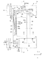
図2は、前パネル7と後パネル8とを接合部9において剥離して前後パネル7,8と中央パネル6とを幅方向Xと前後方向Yとに伸展して得られる展開おむつ1aの部分破断平面図である。前後パネル7,8と中央パネル6とは、図1において上下方向Zへ向いていた向きが図2では前後方向Yへ向くように、その向きが変化している。図2において、これら前パネル7、後パネル8、中央パネル6の形状は幅方向Xの寸法を二等分する中心線Pに関して対称である。
FIG. 2 shows a
図2の前パネル7における前方胴回り弾性部材18は、図1において胴回り開口12の縁12aに沿って胴回り方向へ延びる互いに接近した複数条の上方弾性部材18aと、図1において上下方向Zへ互いに大きく離間して胴回り方向へ延びる複数条の下方弾性部材18bとを含んでいる。図2において、前方胴回り弾性部材18は幅方向Xに伸長された状態にあり、前パネル7の通気性内面シート16と通気性外面シート17とは平坦な状態にあるが、その前方胴回り弾性部材18が収縮すると図1の内外面シート16,17にはひだ70が形成される。
The front waistline
図2の後パネル8は、着用者の肌と向かい合う内面シート21と、着衣と向かい合う通気性外面シート22と、これら内外面シート21,22にサンドウィッチされている後方胴回り弾性部材23とを含んでいる。後方胴回り弾性部材23は、図1において胴回り開口12の縁に沿って胴回り方向へ延びる互いに接近した複数条の上方弾性部材23aと、図1において上方弾性部材23aよりも下方にあって上下方向Zへ互いに大きく離間して胴回り方向へ延びる複数条の下方弾性部材23bとを含んでいる。内外面シート21,22は第4ホットメルト接着剤64を介して互いに接合しており、後方胴回り弾性部材23は内外面シート21,22のうちの少なくとも一方にホットメルト接着剤(図示せず)を介して幅方向Xへ伸長された状態で接合している。図2において内面シート21と外面シート22とは平坦な状態にあるが、前パネル7の場合と同様に、後方胴回り弾性部材23が収縮すると図1の内外面シー21,22にひだ70が形成される。
2 includes an
中央パネル6は、透液性の内面シート31と不透液性の外面シート32と、これら両シート31,32の間に介在する吸液性の芯材33とを含んでいる。内面シート31と外面シート32とは、第2ホットメルト接着剤62を介して接合してある。より、具体的には、内面シート31と外面シート32とは、芯材33の周縁から延出し、第2ホットメルト接着剤62を介して互いに接合して幅方向延出部41と前後方向延出部42とを形成している。幅方向延出部41には中央パネル6の側縁部34が含まれ、その側縁部34は、その内面を形成している内面シート31を内側にし、中心線Pに並行する折曲線38において折曲されている。側縁部34は、幅方向Xの両側それぞれにおいて両端部36,37間に延びている。中央パネル6の幅方向Xにおいて、側縁部34と側縁部34との間に位置する部分は中央パネル6の中央域35であって、中央域35の内面を形成している内面シート31と側縁部34の内面シート31とは、側縁部34のうちの前端部36と後端部37とにおいて、第1ホットメルト接着剤61を介して接合している。側縁部34のうちの前端部36は、前パネル7と中央域35とが側縁部34を介して重なり合う部分であり、後端部37は、後パネル8と中央域35とが側縁部34を介して重なり合う部分である。
The
中央パネル6では、側縁部34を形成している内面シート31と外面シート32との少なくとも二枚のシート部材の間に複数条の脚回り弾性部材39が介在している。弾性部材39には、側縁部34の縁34aに沿って直状に延びる複数条の第1弾性部材39aと、折曲線38の近傍にあって縁34aに向かって凸曲線を画く複数条の第2弾性部材39bとが含まれている。第1,第2弾性部材39a,39bは、前後方向Yへ伸長された状態でホットメルト接着剤(図示せず)を介して内面シート31および/または外面シート32に接合していて、好ましくは側縁部34の前後端部36,37には届くことがない程度に前後方向Yへ延びている。展開おむつ1aが図1のおむつ1に組み立てられて着用されるときには、中央パネル6の中央域35が垂れ下がる一方、弾性部材39が収縮して、側縁部34のうちの前端部36と後端部37との間の部位を中央域35から離間させ、着用者の肌に接近させるように作用する。弾性部材39のうちの第2弾性部材39bは、それを縁34aに向かって凸曲線を画くように側縁部34の内面シート31または外面シート32に取り付けるときに、長さ方向の中央に位置する凸部40aと、長さ方向の両端に位置する直状部40bとの間において伸長率を徐々に変化させることが可能であって、凸部40aの伸長率を特に高くしてある側縁部34では、着用者の肌に対する側縁部34の接触圧をその凸部40aの近傍において特に高くすることができる。
In the
このような側縁部34において、内面シート31と外面シート32とを接合するための第2ホットメルト接着剤62は、低密度塗布域71と高密度塗布域72とを形成するように塗り分けられている。低密度塗布域71においては、側縁部34においての1m2当たりの第2ホットメルト接着剤62の塗布量を高密度塗布域72における塗布量よりも小さくする。図2についていえば、低密度塗布域71は、側縁部34の前後方向Yにおいて、好ましくは前パネル7と後パネル8との間に形成されて、おむつ1の着用中に肌と接触する可能性の高い部分が第2ホットメルト接着剤62の存在によって柔軟性が乏しくなることを防ぐとともに、そのような部分において弾性部材39が伸長・収縮し難くなることを防いでいる。高密度塗布域72は、側縁部34のうちの前端部36および後端部37それぞれの少なくとも一部分に形成されて、おむつ1を着用するときに、内面シート31と外面シート32とが剥離することを防いでいる。高密度塗布域72は、前端部36および後端部37それぞれの面積の全体を占有するように形成されていてもよいのであるが、図示例では幅方向Xの中央部分にのみ形成されている。図示例ではまた、弾性部材39a,39bそれぞれの延長上にあたる部分に低密度塗布域71が形成されているのであるが、弾性部材39a、39bそれぞれの延長上にあたる部分に高密度塗布域72が形成されていると、弾性部材39a,39bがその塗布域72にまで延びているときに、これら弾性部材39a、39bを側縁部34のうちの前端部36と後端部37との間の部分に確実に保持しておくことができる。高密度塗布域72はまた、中央パネル6の側縁部34と中央域35とを強固に接合することに役立つ一方、これらを柔軟性に乏しい部位にすることがあるが、この発明に係るおむつ1においてはそのような部位が生じたとしても、その部位は前パネル7や後パネル8の外側にあって、着用者の肌に接触することがない。
In such a
図3は、図2のIII−III線切断面を示す図である。図3に示された側縁部34の前端部36では、側縁部34と中央域35との間には第1ホットメルト接着剤61の塗布域が形成され、側縁部34には後端部37におけると同様に第2ホットメルト接着剤62の高密度塗布域72が形成され、その高密度塗布域72の両側に低密度塗布域71が形成されている。ちなみに、図示の中央パネル6は、中央パネル6における幅方向延出部41と前後方向延出部42とを含む部分である。
FIG. 3 is a view showing a cross section taken along line III-III in FIG. 2. In the
図3においてはまた、側縁部34の内面と中央パネル6の中央域35における内面とが第1ホットメルト接着剤61を介して接合している。中央域35では、内面シート31と外面シート32とが第2ホットメルト接着剤62を介して接合し、ここでは、第2ホットメルト接着剤62が低密度塗布域71を形成している。中央パネル6は、第3ホットメルト接着剤63を介して前パネル7に接合している。より具体的には、中央パネル6は、折曲されている側縁部34それぞれの外面と、幅方向Xにおいて側縁部34どうしの間に位置する中央域35の内面とにおいて、第3ホットメルト接着剤63を介して前パネル7と後パネル8とに接合してある。前パネル7では、通気性の内面シート16と通気性の外面シート17とが第4ホットメルト接着剤64を介して接合している。
In FIG. 3, the inner surface of the
図4は、図2のIV−IV線切断面を示す図であって、IV−IV線は前パネル7の下縁7d(図1参照)の近傍にある。図4に示された側縁部34の前端部36では、中央パネル6と前パネル7とが接合しておらず、図1のおむつ1では、中央パネル6と前パネル7とが互いに離間可能な状態にある。中央パネル6と前パネル7とについてのその他の構造は、図3と同様な構造である。
FIG. 4 is a diagram showing a section taken along the line IV-IV in FIG. 2, and the line IV-IV is in the vicinity of the
図5は、図3のV−V線切断面を示している。図示の中央パネル6は、体液吸収性の芯材33と、幅方向延出部41とを含んでいる。幅方向延出部41の一部分は折曲線38で折曲されていて、弾性部材39を含む側縁部34を形成している。その側縁部34では、第2ホットメルト接着剤62が低密度塗布域71を形成している。中央パネル6の中央域35には、体液吸収性の芯材33と、幅方向延出部41の一部分とが含まれている。展開おむつ1aが組み立てられて図1のおむつ1になると、中央域35が仮想線の如く垂れ下がる一方、弾性部材39が収縮することに伴い、側縁部34が仮想線の如き状態になる。
FIG. 5 shows a cross section taken along the line VV of FIG. The illustrated
このように形成されているおむつ1およびおむつ1aにおいて、第1〜第4ホットメルト接着剤61〜64には、スチレン系、スチレン・ブタジエン系、スチレン・ブタジエン・スチレン系、アクリル系等の当該分野において慣用のものを使用することができる。これら第1〜第4ホットメルト接着剤61〜64の塗布には、スパイラルスプレーコータやバーコータ等の慣用の塗布機を使用することができ、ドット状やスパイラル状、ビード状等の塗布パターンを採用することができる。これらホットメルト接着剤の塗布量は、接合すべき面積1m2当たりについて5〜30gであることが好ましい。ただし、第2ホットメルト接着剤62については、低密度塗布域71においての1m2当たりの塗布量が0.3〜3gの範囲にあり、高密度塗布域72においての1m2当たりの塗布量が5〜30gの範囲にあるように塗布量を調整することが好ましい。
In the diaper 1 and the
図1のおむつ1は、それを着用するときに、着用者のつま先が側縁部34に引っ掛かるとか、つま先で中央パネル6の中央域35をおむつ1の外側に向かって押すとかということがある。両手で前パネル7や後パネル8を持っているときにそうしたことが生じると、中央パネル6は、例えば前パネル7に対して図1に矢印Rで示されている方向へ動いて前パネル7から剥離するような作用を受けるとか、中央域35が側縁部34から剥離するような作用を受けるとか、側縁部34において内面シート31と外面シート32とが剥離するような作用を受けるとかということがある。これらの作用によるシートどうしの剥離を防ぐには、おむつ1において、第1〜第4ホットメルト接着剤61〜64の塗布量と塗布範囲とを大きくするような対策を講じればよいのであるが、側縁部34の内面シート31と外面シート32とに単純にそのような対策を適用すると、側縁部34を柔軟性の乏しいものにしかねないという問題がある。しかし、図1のおむつ1を例とするこの発明の着用物品では、側縁部34に使用する第2ホットメルト接着剤62を低密度塗布域71と高密度塗布域72との間において塗り分けるので、そのような問題の発生を防ぐことができる。
The diaper 1 of FIG. 1 may be that the wearer's toe is caught on the
図6,7は、この発明の実施態様の一例を示す図2と同様な図と、図6のVII−VII線切断面を示す図であって、図7は図5と同様な図でもある。ただし、図6の展開おむつ1aは、図2の展開おむつ1aと異なり、中央パネル6において側縁部34と中央域35とを接合するための第1ホットメルト接着剤61の塗布域が側縁部34のうちの前端部36のみならず、後パネル8に向かって前パネル7の下縁7dを越えるように広がっている。図示してはいないが、側縁部34の後端部37における第1ホットメルト接着剤61の塗布状態は、前端部36における図6の状態と同様であって、第1ホットメルト接着剤61の塗布域は後端部37のみならず、前パネル7に向かって後パネル8の下縁8d(図1,2参照)を越えるように広がっている。おむつ1がこのような態様にあると、おむつ1が着用されるときや着用しているときの側縁部34と中央域35との剥離を防ぐ効果が向上する。なお、図7の側縁部34における外面シート32の態様は、外面シート32が側縁部34の縁34aで折曲されて、内面シート31に重なるとともに第2ホットメルト接着剤62を介して接合していることにおいて、図5における外面シート32の態様と異なっている。
6 and 7 are views similar to FIG. 2 showing an example of the embodiment of the present invention and a view taken along the line VII-VII in FIG. 6, and FIG. 7 is also a view similar to FIG. . However, the unfolded
図8もまた、この発明の実施態様の一例を示す図5と同様な図である。図8の構造を有する展開おむつ1aは、中央パネル6の内面シート31と外面シート32との間に図2,5に例示の芯材33を含んでおらず、その芯材33に代わる芯材33よりも幅の広い体液吸収性のパッド75がその一部分を側縁部34と中央域35との間に挿入された状態で中央パネル6の内面にセットされている。パッド75は、体液吸収性の芯材76を液透過性の内面シート77と液不透過性の外面シート78とでサンドウィッチすることにより形成されている。パッド75は、中央パネル6に対して自由にセットしたり外したりすることができるもので、中央パネル6に対してのセット状態を安定化させるために、中央パネル6と対向する部位に粘着剤を塗布したり、メカニカルファスナを取り付けたりすることができる。このような展開おむつ1aから得るおむつ1は、パッド75が交換可能であるおむつ、またはパッド75を使用するためのおむつカバーと呼ぶことができるものでもある。
FIG. 8 is also a view similar to FIG. 5 showing an example of the embodiment of the present invention. The unfolded
図示例のおむつ1およびおむつ1aにおいて、前パネル7の内面シート16や外面シート17,後パネル8の内面シート21や外面シート22には、熱可塑性合成繊維で形成された不織布やプラスチックフィルム、これら不織布とプラスチックフィルムとの積層シート等を使用することができる。中央パネルにおける内面シート31には、熱可塑性合成繊維で形成された透液性の不織布や開孔プラスチックフィルム等を使用することができる。外面シート32には不透液性のプラスチックフィルムを使用することができるが、そのプラスチックフィルムの外面に対して熱可塑性合成繊維で形成された不織布を積層しておくと、中央パネル6の外面の肌触りを布様のものにすることができる。また、不織布が積層してあるときのプラスチックフィルムは、図2における幅方向Xと前後方向Yとの寸法を芯材33の寸法よりも僅かに大きい程度にしておいて、積層してある不織布を幅方向延出部41における内面シート31として使用することができる。図2の芯材33および図8のパッド75における芯材76は、粉砕パルプや粉砕パルプと高吸水性ポリマー粒子との混合物等の吸水性材料の集合体をティッシュペーパや透液性の不織布等で形成されたラッピングシートで被覆することにより得ることができる。
In the illustrated diaper 1 and
1 使い捨てのパンツ型着用物品(おむつ)
6 中央パネル
7 前パネル
8 後パネル
34 側縁部
35 中央域
36 端部
37 端部
61 第1ホットメルト接着剤
62 第2ホットメルト接着剤
71 低密度塗布域
72 高密度塗布域
X 幅方向
Y 前後方向
Z 上下方向
1 Disposable pants-type wearing articles (diapers)
6
Claims (4)
前記前パネルと前記後パネルと前記中央パネルとは、前記着用物品の着用者の肌と向かい合う内面と、その反対面である外面とを有し、
前記中央パネルは、内面シートと、外面シートと、前記内面シート及び前記外面シートの間に介在する吸液性の芯材とを含み、前記幅方向において、中央域と、前記内面シートを内側にし、折曲線において折曲された側縁部とを有し、
前記中央パネルの前記側縁部は、前記幅方向の両側それぞれにおいて前記両端部間に延び、前記折曲線で折曲されることにより前記中央域の前記内面シートに重ねられ、
前記中央パネルは、前記中央域の前記内面シートと前記側縁部の前記内面シートとが、前記両端部において第1ホットメルト接着剤を介して接合され、
前記中央パネルにおける前記内面シートと前記外面シートとは、第2ホットメルト接着剤を介して接合され、
前記中央パネルの前記側縁部において、前記内面シートと前記外面シートとの間には伸長状態で前記上下方向へ延びている複数条の弾性部材が介在し、
前記中央パネルは、折曲されている前記側縁部それぞれの外面と、前記幅方向において前記側縁部どうしの間に位置する前記中央域の内面とにおいて、第3ホットメルト接着剤を介して前記前パネルと前記後パネルとに接合し、
前記中央パネルの前記側縁部における前記第2ホットメルト接着剤の前記内面シート及び前記外面シートに対する塗布域には、1m2当たりの塗布量が多い高密度塗布域と、1m2当りの塗布量が少ない低密度塗布域とが含まれ、前記高密度塗布域が前記両端部のうちの前記少なくとも一部分に含まれていることを特徴とする前記着用物品。 Including a front panel, a rear panel, and a center panel, each of the panels having a width direction and a vertical direction perpendicular to each other, and the front panel and the rear panel are joined to each other on both sides in the width direction. Forming a waistline region in a state in which the circumferential direction is connected, wherein the central panel is bent so as to form a U-shape in the vertical direction, and at least a part of one of both end portions located above the vertical direction is A disposable pants-type wearing article that is joined to the front panel from the outside of the waistline region, and at least a part of the other end portion is joined to the rear panel from the outside,
The front panel, the rear panel, and the center panel have an inner surface facing the skin of a wearer of the wearing article, and an outer surface that is the opposite surface.
The central panel includes an inner surface sheet, an outer surface sheet, and a liquid-absorbent core material interposed between the inner surface sheet and the outer surface sheet, and in the width direction, the central region and the inner surface sheet are disposed inside. A side edge bent at the folding line,
The side edge portion of the central panel extends between the both end portions on both sides in the width direction, and is overlapped with the inner surface sheet in the central region by being bent along the folding line.
In the central panel, the inner surface sheet of the central region and the inner surface sheet of the side edge portion are joined via a first hot melt adhesive at the both end portions,
The inner sheet and the outer sheet in the center panel are bonded via a second hot melt adhesive,
In the side edge portion of the central panel, a plurality of elastic members extending in the up-down direction in an expanded state are interposed between the inner sheet and the outer sheet,
The center panel has a third hot melt adhesive interposed between an outer surface of each of the bent side edges and an inner surface of the center area located between the side edges in the width direction. Bonding to the front panel and the rear panel,
The side of the coating zone to said inner sheet and said outer sheet of the second hot-melt adhesive at the edge, dense coating zone coating amount is large per 1 m 2 and, 1 m 2 per coating amount of said central panel And the low-density coating area is included, and the high-density coating area is included in the at least part of the both ends.
Priority Applications (5)
| Application Number | Priority Date | Filing Date | Title |
|---|---|---|---|
| JP2010223228A JP5766421B2 (en) | 2010-09-30 | 2010-09-30 | Disposable pants-type wearing articles |
| CN201180047134.3A CN103140202B (en) | 2010-09-30 | 2011-09-08 | Disposable pant-type clothing article |
| EP11828749.9A EP2623080B1 (en) | 2010-09-30 | 2011-09-08 | Disposable pant-type clothing article |
| US13/823,442 US9101511B2 (en) | 2010-09-30 | 2011-09-08 | Disposable pants-type wearing article |
| PCT/JP2011/070513 WO2012043188A1 (en) | 2010-09-30 | 2011-09-08 | Disposable pant-type clothing article |
Applications Claiming Priority (1)
| Application Number | Priority Date | Filing Date | Title |
|---|---|---|---|
| JP2010223228A JP5766421B2 (en) | 2010-09-30 | 2010-09-30 | Disposable pants-type wearing articles |
Publications (3)
| Publication Number | Publication Date |
|---|---|
| JP2012075648A JP2012075648A (en) | 2012-04-19 |
| JP2012075648A5 JP2012075648A5 (en) | 2013-10-24 |
| JP5766421B2 true JP5766421B2 (en) | 2015-08-19 |
Family
ID=45892661
Family Applications (1)
| Application Number | Title | Priority Date | Filing Date |
|---|---|---|---|
| JP2010223228A Expired - Fee Related JP5766421B2 (en) | 2010-09-30 | 2010-09-30 | Disposable pants-type wearing articles |
Country Status (5)
| Country | Link |
|---|---|
| US (1) | US9101511B2 (en) |
| EP (1) | EP2623080B1 (en) |
| JP (1) | JP5766421B2 (en) |
| CN (1) | CN103140202B (en) |
| WO (1) | WO2012043188A1 (en) |
Families Citing this family (7)
| Publication number | Priority date | Publication date | Assignee | Title |
|---|---|---|---|---|
| JP5297862B2 (en) * | 2009-03-31 | 2013-09-25 | ユニ・チャーム株式会社 | Wearing article |
| JP5822475B2 (en) * | 2011-01-31 | 2015-11-24 | ユニ・チャーム株式会社 | Disposable pants-type wearing articles |
| JP5968117B2 (en) * | 2012-06-26 | 2016-08-10 | ユニ・チャーム株式会社 | Disposable wearing items |
| JP2014147565A (en) * | 2013-02-01 | 2014-08-21 | Uni Charm Corp | Absorbent article |
| JP6211777B2 (en) | 2013-03-18 | 2017-10-11 | 株式会社リブドゥコーポレーション | Absorbent articles |
| CN112789018B (en) * | 2018-10-01 | 2022-04-05 | 花王株式会社 | Disposable diaper having a disposable diaper |
| CN113576762B (en) * | 2021-08-11 | 2022-04-29 | 上海护理佳实业有限公司 | Breast pad |
Family Cites Families (13)
| Publication number | Priority date | Publication date | Assignee | Title |
|---|---|---|---|---|
| JPH071860Y2 (en) | 1989-05-29 | 1995-01-18 | 株式会社ケンウッド | Signal level adjuster |
| JP2511428Y2 (en) * | 1990-07-11 | 1996-09-25 | 株式会社資生堂 | Disposable diapers |
| JP2774441B2 (en) | 1993-12-16 | 1998-07-09 | トーヨー衛材株式会社 | Disposable pants |
| JP2003102785A (en) * | 2001-10-01 | 2003-04-08 | Uni Charm Corp | Disposable diaper |
| TWI224963B (en) * | 2002-05-31 | 2004-12-11 | Kao Corp | Briefs-type diaper and briefs-type absorbent article |
| US7837665B2 (en) * | 2002-10-01 | 2010-11-23 | Kimberly-Clark Worldwide, Inc. | Three-piece disposable undergarment with folded crotch member |
| JP4240463B2 (en) | 2003-04-30 | 2009-03-18 | 株式会社リブドゥコーポレーション | Pants-type diapers |
| JP4298377B2 (en) * | 2003-05-22 | 2009-07-15 | ユニ・チャーム株式会社 | Disposable pants-type wearing articles |
| CL2004001285A1 (en) | 2003-05-27 | 2005-04-15 | Procter & Gamble | A DISPOSABLE GARMENT THAT IS REMOVED AND SET, WITH OPENINGS FOR WAIST AND LEGS, WHICH INCLUDES; MAIN ABSORBENT BODY WITH UPPER LEAF, LOWER LEAF AND NUCELO; ELASTIC BELT SIMILAR TO A RING WITH CENTRAL AND SIDE PANEL; AND CAPE CUB |
| JP2006051240A (en) | 2004-08-13 | 2006-02-23 | Uni Charm Corp | Simple diaper |
| EP2120828B1 (en) * | 2006-12-22 | 2013-12-18 | Sca Hygiene Products AB | A pant-type absorbent article and a method for producing pant-type absorbent articles |
| JP5002373B2 (en) * | 2007-08-29 | 2012-08-15 | ユニ・チャーム株式会社 | Composite sheet |
| CN101835443B (en) * | 2007-09-05 | 2014-03-05 | 尤妮佳股份有限公司 | Absorptive article |
-
2010
- 2010-09-30 JP JP2010223228A patent/JP5766421B2/en not_active Expired - Fee Related
-
2011
- 2011-09-08 WO PCT/JP2011/070513 patent/WO2012043188A1/en active Application Filing
- 2011-09-08 US US13/823,442 patent/US9101511B2/en not_active Expired - Fee Related
- 2011-09-08 EP EP11828749.9A patent/EP2623080B1/en not_active Not-in-force
- 2011-09-08 CN CN201180047134.3A patent/CN103140202B/en not_active Expired - Fee Related
Also Published As
| Publication number | Publication date |
|---|---|
| WO2012043188A1 (en) | 2012-04-05 |
| EP2623080B1 (en) | 2017-03-15 |
| US20130172841A1 (en) | 2013-07-04 |
| CN103140202B (en) | 2015-04-15 |
| CN103140202A (en) | 2013-06-05 |
| EP2623080A1 (en) | 2013-08-07 |
| US9101511B2 (en) | 2015-08-11 |
| JP2012075648A (en) | 2012-04-19 |
| EP2623080A4 (en) | 2015-06-24 |
Similar Documents
| Publication | Publication Date | Title |
|---|---|---|
| EP2760407B1 (en) | Disposable wearing article | |
| JP5766421B2 (en) | Disposable pants-type wearing articles | |
| CN106794090B (en) | Disposable wearing article | |
| TWI584793B (en) | Dispose of items with disposable dessert | |
| WO2011102427A1 (en) | Disposable wearing article | |
| KR102179940B1 (en) | Wearing article | |
| JP5525254B2 (en) | Disposable diapers | |
| JP4920892B2 (en) | Disposable pants-type wearing articles | |
| JP5777271B2 (en) | Wearing article | |
| JP2017148111A (en) | Underpants type absorbent article | |
| JP2007097920A (en) | Disposable diaper | |
| JP5907603B2 (en) | Disposable wearing items | |
| JP6230351B2 (en) | Disposable wearing items | |
| JP2004350809A (en) | Pants-shaped disposable diaper | |
| JP6830134B2 (en) | Disposable diapers and how to make them | |
| JP6057505B2 (en) | Disposable wearing items | |
| JP2016000116A (en) | Disposable clothing article | |
| JP2014108271A (en) | Absorbent article | |
| JP6006373B1 (en) | Pants-type absorbent article | |
| JP6415399B2 (en) | Disposable wearing items | |
| JP5906045B2 (en) | Disposable wearing items | |
| CN110536667B (en) | Method for manufacturing absorbent article | |
| JP6436771B2 (en) | Disposable wearing articles | |
| JP6415319B2 (en) | Disposable diapers | |
| JP6316707B2 (en) | Pants-type absorbent article |
Legal Events
| Date | Code | Title | Description |
|---|---|---|---|
| A521 | Request for written amendment filed |
Free format text: JAPANESE INTERMEDIATE CODE: A523 Effective date: 20130909 |
|
| A621 | Written request for application examination |
Free format text: JAPANESE INTERMEDIATE CODE: A621 Effective date: 20130909 |
|
| A131 | Notification of reasons for refusal |
Free format text: JAPANESE INTERMEDIATE CODE: A131 Effective date: 20140924 |
|
| A521 | Request for written amendment filed |
Free format text: JAPANESE INTERMEDIATE CODE: A523 Effective date: 20141117 |
|
| TRDD | Decision of grant or rejection written | ||
| A01 | Written decision to grant a patent or to grant a registration (utility model) |
Free format text: JAPANESE INTERMEDIATE CODE: A01 Effective date: 20150519 |
|
| A61 | First payment of annual fees (during grant procedure) |
Free format text: JAPANESE INTERMEDIATE CODE: A61 Effective date: 20150617 |
|
| R150 | Certificate of patent or registration of utility model |
Ref document number: 5766421 Country of ref document: JP Free format text: JAPANESE INTERMEDIATE CODE: R150 |
|
| R250 | Receipt of annual fees |
Free format text: JAPANESE INTERMEDIATE CODE: R250 |
|
| R250 | Receipt of annual fees |
Free format text: JAPANESE INTERMEDIATE CODE: R250 |
|
| R250 | Receipt of annual fees |
Free format text: JAPANESE INTERMEDIATE CODE: R250 |
|
| R250 | Receipt of annual fees |
Free format text: JAPANESE INTERMEDIATE CODE: R250 |
|
| R250 | Receipt of annual fees |
Free format text: JAPANESE INTERMEDIATE CODE: R250 |
|
| LAPS | Cancellation because of no payment of annual fees |