JP5763783B2 - Method and apparatus for compiling regular expressions - Google Patents
Method and apparatus for compiling regular expressions Download PDFInfo
- Publication number
- JP5763783B2 JP5763783B2 JP2013550669A JP2013550669A JP5763783B2 JP 5763783 B2 JP5763783 B2 JP 5763783B2 JP 2013550669 A JP2013550669 A JP 2013550669A JP 2013550669 A JP2013550669 A JP 2013550669A JP 5763783 B2 JP5763783 B2 JP 5763783B2
- Authority
- JP
- Japan
- Prior art keywords
- automaton
- state
- states
- quantification
- netlist
- Prior art date
- Legal status (The legal status is an assumption and is not a legal conclusion. Google has not performed a legal analysis and makes no representation as to the accuracy of the status listed.)
- Active
Links
Images


Classifications
-
- G—PHYSICS
- G06—COMPUTING; CALCULATING OR COUNTING
- G06F—ELECTRIC DIGITAL DATA PROCESSING
- G06F8/00—Arrangements for software engineering
- G06F8/40—Transformation of program code
-
- G—PHYSICS
- G06—COMPUTING; CALCULATING OR COUNTING
- G06F—ELECTRIC DIGITAL DATA PROCESSING
- G06F8/00—Arrangements for software engineering
- G06F8/40—Transformation of program code
- G06F8/41—Compilation
-
- G—PHYSICS
- G06—COMPUTING; CALCULATING OR COUNTING
- G06F—ELECTRIC DIGITAL DATA PROCESSING
- G06F30/00—Computer-aided design [CAD]
- G06F30/30—Circuit design
-
- G—PHYSICS
- G06—COMPUTING; CALCULATING OR COUNTING
- G06F—ELECTRIC DIGITAL DATA PROCESSING
- G06F30/00—Computer-aided design [CAD]
- G06F30/30—Circuit design
- G06F30/34—Circuit design for reconfigurable circuits, e.g. field programmable gate arrays [FPGA] or programmable logic devices [PLD]
-
- G—PHYSICS
- G06—COMPUTING; CALCULATING OR COUNTING
- G06F—ELECTRIC DIGITAL DATA PROCESSING
- G06F30/00—Computer-aided design [CAD]
- G06F30/30—Circuit design
- G06F30/34—Circuit design for reconfigurable circuits, e.g. field programmable gate arrays [FPGA] or programmable logic devices [PLD]
- G06F30/343—Logical level
-
- G—PHYSICS
- G06—COMPUTING; CALCULATING OR COUNTING
- G06F—ELECTRIC DIGITAL DATA PROCESSING
- G06F30/00—Computer-aided design [CAD]
- G06F30/30—Circuit design
- G06F30/34—Circuit design for reconfigurable circuits, e.g. field programmable gate arrays [FPGA] or programmable logic devices [PLD]
- G06F30/347—Physical level, e.g. placement or routing
-
- G—PHYSICS
- G06—COMPUTING; CALCULATING OR COUNTING
- G06F—ELECTRIC DIGITAL DATA PROCESSING
- G06F8/00—Arrangements for software engineering
- G06F8/40—Transformation of program code
- G06F8/41—Compilation
- G06F8/42—Syntactic analysis
- G06F8/427—Parsing
-
- G—PHYSICS
- G06—COMPUTING; CALCULATING OR COUNTING
- G06F—ELECTRIC DIGITAL DATA PROCESSING
- G06F8/00—Arrangements for software engineering
- G06F8/40—Transformation of program code
- G06F8/41—Compilation
- G06F8/44—Encoding
- G06F8/443—Optimisation
-
- G—PHYSICS
- G06—COMPUTING; CALCULATING OR COUNTING
- G06F—ELECTRIC DIGITAL DATA PROCESSING
- G06F8/00—Arrangements for software engineering
- G06F8/40—Transformation of program code
- G06F8/41—Compilation
- G06F8/44—Encoding
- G06F8/447—Target code generation
-
- G—PHYSICS
- G06—COMPUTING; CALCULATING OR COUNTING
- G06F—ELECTRIC DIGITAL DATA PROCESSING
- G06F9/00—Arrangements for program control, e.g. control units
- G06F9/06—Arrangements for program control, e.g. control units using stored programs, i.e. using an internal store of processing equipment to receive or retain programs
- G06F9/44—Arrangements for executing specific programs
- G06F9/448—Execution paradigms, e.g. implementations of programming paradigms
- G06F9/4498—Finite state machines
Description
〔優先権主張〕
本特許出願は、2011年1月25日に出願された、「METHOD AND APPARATUS FOR COMPILING REGULAR EXPRESSIONS」という名称の米国仮特許出願整理番号61/436,013に対する優先権の利益を主張し、これによって、参照によりその全体として本明細書に組み込まれる。
[Priority claim]
This patent application claims priority benefit to US Provisional Patent Application Serial No. 61 / 436,013, filed January 25, 2011, entitled “METHOD AND APPARATUS FOR COMPILING REGULAR EXPRESSIONS”. , Incorporated herein by reference in its entirety.
有限状態機械(FSM)(有限状態オートマトン、オートマトン、または単に状態機械とも呼ばれる)は、状態、状態と動作との間の遷移の表現である。有限状態機械は、並列マシン用のデジタル論理、コンピュータプログラム、またはイメージを設計するために使用できる。有限状態機械は、有限数の状態、それら状態間の遷移、および出力から成る挙動のモデルである。有限状態機械は、グラフとして表すことができ、グラフのバーテックスが有限状態機械の状態に対応し、グラフのエッジが、有限状態機械に対する1つまたは複数の入力に起因して生じる状態間の遷移に対応する。有限状態機械は、確率的遷移、ファジー状態、または他の奇妙な事柄(oddity)も持つことができる。有限状態機械は、有限の内部メモリ、入力特徴、および随意の出力特徴を有する。出力を有する有限状態機械は、有限状態トランスデューサと呼ぶことができる。 A finite state machine (FSM) (also called a finite state automaton, an automaton, or simply a state machine) is a representation of transitions between states, states and actions. Finite state machines can be used to design digital logic, computer programs, or images for parallel machines. A finite state machine is a model of behavior consisting of a finite number of states, transitions between those states, and outputs. A finite state machine can be represented as a graph, where the vertex of the graph corresponds to the state of the finite state machine, and the edges of the graph represent transitions between states caused by one or more inputs to the finite state machine. Correspond. A finite state machine can also have stochastic transitions, fuzzy states, or other oddities. A finite state machine has a finite internal memory, input features, and optional output features. A finite state machine having an output can be referred to as a finite state transducer.
有限状態機械の用途には、コンピュータによる電子設計の自動化、通信プロトコル設計、生物学および人工知能研究、ならびに自然言語の文法を説明する言語学を含む。 Applications of finite state machines include computerized electronic design automation, communication protocol design, biology and artificial intelligence research, and linguistics describing natural language grammar.
以下の説明および図は、特定の実施形態を当業者が実施できるように十分に説明する。他の実施形態は、構造的、論理的、電気的、プロセス、および他の変更を包含し得る。いくつかの実施形態の部分および特徴は、他の実施形態に含まれ得るか、または他の実施形態のそれらと置き換えられ得る。請求項に規定される実施形態は、それらの請求項の全ての利用可能な均等物を包含する。 The following description and figures sufficiently describe certain embodiments to enable those skilled in the art to practice the embodiments. Other embodiments may include structural, logical, electrical, process, and other changes. Parts and features of some embodiments may be included in other embodiments or replaced with those of other embodiments. Embodiments defined in the claims encompass all available equivalents of those claims.
本文書では、特に、並列マシンを構成する(例えば、プログラム化する)ために、ソースコード(例えば、正規表現)を機械コード(例えば、イメージ)に変換するためのコンパイラを説明する。コンパイラによって生成されたイメージ(出力ファイル)は、ある機能を実行するために並列マシンをプログラムできる。ある例では、並列マシンは、有限状態機械(FSM)エンジン、フィールドプログラマブルゲートアレイ(FPGA)、およびそれらの変形形態を含み得る。 This document specifically describes a compiler for converting source code (eg, regular expressions) to machine code (eg, images) to configure (eg, program) a parallel machine. The image (output file) generated by the compiler can program a parallel machine to perform certain functions. In one example, the parallel machine may include a finite state machine (FSM) engine, a field programmable gate array (FPGA), and variations thereof.
図1は、対象装置(例えば、並列マシン100)の一例を示す。並列マシン100は、入力データを受信し、その入力データに基づいて出力を提供できる。並列マシン100は、入力データを受信するためのデータ入力ポート110および出力を別の装置に提供するための出力ポート114を含むことができる。データ入力ポート110は、並列マシン100に入力されるデータ用のインタフェースを提供する。
FIG. 1 shows an example of a target device (for example, a parallel machine 100). The
並列マシン100は、汎用要素102および専用要素112を含む、複数のプログラム可能要素を含む。汎用要素102は、1つまたは複数の入力104および1つまたは複数の出力106を含み得る。汎用要素102は、複数の状態のうちの1つにプログラムされ得る。汎用要素102の状態は、汎用要素102が、所与の入力に基づいて、何の出力を提供するかを決定する。すなわち、汎用要素102の状態は、プログラム可能要素が所与の入力に対してどのように反応する(例えば、応答する)かを決定する。データ入力ポート110に対するデータ入力は、汎用要素102にそれに対する処置を取らせるため、複数の汎用要素102に提供され得る。汎用要素102の例には、例えば、他のプログラム可能要素の中で、状態機械要素(SME)、以下で詳細に説明するように、カウンタ、および/または構成可能論理ブロックを含むことができる。一例では、SMEは、所与の入力がデータ入力ポート110で受信される場合に、特定の出力(例えば、高信号つまり「1」信号)を提供するようにプログラム(例えば、設定)され得る。所与の入力以外の入力がデータ入力ポート110で受信される場合、SMEは異なる出力(例えば、低信号つまり「0」信号)を提供し得る。一例では、構成可能論理ブロックは、データ入力ポート110で受信された入力に基づいて、ブール論理関数(例えば、AND、OR、NORなど)を実行するように設定できる。カウンタの例については、本明細書において後で説明する。専用要素112は、メモリ(例えば、RAM)、論理ゲート、カウンタ、ルックアップテーブル、フィールドプログラマブルゲートアレイ(FPGA)、および他のハードウェア要素を含むことができる。専用要素112は、汎用要素102とやりとりすることができ、専用機能を実行する。
並列マシン100は、プログラム(例えば、イメージ)を並列マシン100上にロードするためのプログラミングインタフェース111も含むことができる。イメージは、汎用要素102の状態をプログラム(例えば、設定)できる。すなわち、イメージは、所与の入力に対して特定の方法で反応するように汎用要素102を構成できる。例えば、汎用要素102は、文字‘a’がデータ入力ポート110で受信される場合、高信号を出力するように設定できる。いくつかの例では、並列マシン100は、汎用要素102の動作のタイミングを制御するためのクロック信号を使用できる。いくつかの実施形態では、データ入力ポート110で受信されるデータは、長い時間をかけて、もしくは一度にそろって受信されたデータの一定のセット、または長い時間をかけて受信されたデータのストリームを含むことができる。データは、並列マシン100に結合された、データベース、センサー、ネットワークなどの任意のソースから受信され得るか、またはそれらによって生成され得る。
The
並列マシン100は、並列マシン100の異なる要素(例えば、汎用要素102、データ入力ポート110、出力ポート114、プログラミングインタフェース111、および専用要素112)を選択的に共に結合するための複数のプログラム可能スイッチ108も含む。その結果、並列マシン100は、要素間で形成されたプログラム可能マトリックス(programmable matrix)を含む。一例では、汎用要素102の入力104、データ入力ポート110、プログラミングインタフェース111、または専用要素112が、1つまたは複数のプログラム可能スイッチ108を通して、汎用要素102の出力106、出力ポート114、プログラミングインタフェース111、または専用要素112に結合できるように、プログラム可能スイッチ108が、2つ以上の要素を選択的に互いに結合できる。従って、要素間の信号のルーティングが、プログラム可能スイッチ108を設定することによって制御できる。図1は、所与の要素とプログラム可能スイッチ108との間の特定数の導体(例えば、ワイヤー)を示しているが、他の例では、異なる数の導体が使用できることが理解されるはずである。また、図1は、個別にプログラム可能スイッチ108に結合された各汎用要素102を示しているが、他の例では、複数の汎用要素102がグループ(例えば、図2に示すような、ブロック202)としてプログラム可能スイッチ108に結合できる。一例では、データ入力ポート110、データ出力ポート114、および/またはプログラミングインタフェース111はレジスタとして実装でき、レジスタへの書込みが、それぞれの要素にデータを提供するか、またはそれぞれの要素からデータを提供するようにする。
一例では、単一の並列マシン100が物理デバイス上に実装されるが、他の例では、2つ以上の並列マシン100が単一の物理デバイス(例えば、物理チップ)上に実装できる。一例では、複数の並列マシン100の各々が、別個のデータ入力ポート110、別個の出力ポート114、別個のプログラミングインタフェース111、および汎用要素102の別個のセットを含むことができる。さらに、汎用要素102の各セットは、それらの対応する入力データポート110でデータに反応(例えば、高信号または低信号を出力)できる。例えば、第1の並列マシン100に対応する汎用要素102の第1のセットは、第1の並列マシン100に対応する第1のデータ入力ポート110でデータに反応できる。第2の並列マシン100に対応する汎用要素102の第2のセットは、第2の並列マシン100に対応する第2のデータ入力ポート110に反応できる。その結果、各並列マシン100は、1セットの汎用要素102を含み、異なるセットの汎用要素102は、異なる入力データに反応できる。同様に、各並列マシン100、および汎用要素102の各対応するセットは、別個の出力を提供できる。いくつかの例では、第2の並列マシン100に対する入力データが、第1の並列マシン100からの出力データを含むことができるように、第1の並列マシン100からの出力ポート114が、第2の並列マシン100の入力ポート110に結合できる。
In one example, a single
一例では、並列マシン100上にロードするためのイメージは、汎用要素102の状態を設定するため、プログラム可能スイッチ108をプログラミングするため、および並列マシン100内で専用要素112を構成するための複数のビットの情報を含む。一例では、ある入力に基づいて所望の出力を提供するように並列マシン100をプログラムするために、イメージが並列マシン100上にロードできる。出力ポート114は、入力ポート110で受信されたデータに対する汎用要素102の反応に基づいて、並列マシン100からの出力を提供できる。出力ポート114からの出力は、所与のパターンの一致を示す単一ビット、複数のパターンに対する一致および不一致を示す複数のビットを含むワード(word)、ならびに所与の時に全てまたは特定の汎用要素102の状態に対応する出力ベクトルを含むことができる。
In one example, an image for loading on
並列マシン100に関する使用例には、パターン認識(例えば、音声認識、画像認識など)、信号処理、画像処理、コンピュータビジョン、暗号化、およびその他を含む。ある例では、並列マシン100は、有限状態機械(FSM)エンジン、フィールドプログラマブルゲートアレイ(FPGA)、およびそれらの変形を含むことができる。さらに、並列マシン100は、コンピュータ、ポケットベル、携帯電話、電子手帳、携帯音楽プレーヤ、ネットワーク装置(例えば、ルータ、ファイアウォール、スイッチ、またはそれらの任意の組合せ)、制御回路、カメラなどの、大きな装置内のコンポーネントであり得る。
Examples of uses for
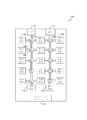
図2〜図5は、有限状態機械(FSM)エンジン200として実装された別の並列マシンを示す。一例では、FSMエンジン200は、有限状態機械のハードウェア実装を含む。その結果、FSMエンジン200は、FSM内の複数の状態に対応する、複数の選択的に結合可能なハードウェア要素(例えば、プログラム可能要素)を実装する。FSM内の状態と同様に、ハードウェア要素は、入力ストリームを分析し、その入力ストリームに基づいて下流のハードウェア要素をアクティブにできる。
2-5 illustrate another parallel machine implemented as a finite state machine (FSM)
FSMエンジン200は、汎用要素および専用要素を含む、複数のプログラム可能要素を含む。汎用要素は、多数の異なる機能を実装するようにプログラムされ得る。これらの汎用要素は、行(row)206(図3および図4に示す)およびブロック202(図2および図3に示す)に階層的に編成されているSME 204、205(図5に示す)を含む。階層的に編成されたSME 204、205間で信号をルーティングするために、ブロック間スイッチ203(図2および図3に示す)、ブロック内スイッチ208(図3および図4に示す)、ならびに行内(intra−row)スイッチ212(図4に示す)を含む、プログラム可能スイッチの階層が使用される。SME 204、205は、FSMエンジン200によって実装されたFSMの状態に対応できる。SME 204、205は、以下で説明するように、プログラム可能スイッチの使用によって共に結合できる。その結果、FSMは、状態の機能に対応するようにSME 204、205をプログラミングすることにより、また、FSM内の状態間の遷移に対応するため、SME 204、205を選択的に共に結合することにより、FSMエンジン200上に実装できる。
The
図2は、FSMエンジン例200の全体図を示す。FSMエンジン200は、プログラム可能ブロック間スイッチ203と選択的に共に結合できる複数のブロック202を含む。さらに、ブロック202は、信号(例えば、データ)を受信するため、およびデータをブロック202に提供するために、入力ブロック209(例えば、データ入力ポート)に選択的に結合できる。ブロック202は、ブロック202から外部デバイス(例えば、別のFSMエンジン200)に信号を提供するために、出力ブロック213(例えば、出力ポート)にも選択的に結合できる。FSMエンジン200は、プログラム(例えば、イメージ)をFSMエンジン200上にロードするために、プログラミングインタフェース211も含み得る。イメージは、SME 204、205の状態をプログラム(設定)できる。すなわち、イメージは、入力ブロック209で所与の入力に対して特定の方法で反応するように、SME 204、205を構成できる。例えば、SME 204は、入力ブロック209で文字「a」が受信される場合、高信号を出力するように設定できる。
FIG. 2 shows an overall view of an
一例では、入力ブロック209、出力ブロック213、および/またはプログラミングインタフェース211はレジスタとして実装でき、そのレジスタへの書込みがそれぞれの要素に対して、またはそれぞれの要素から、データを提供できるようにする。その結果、プログラミングインタフェース211に対応するレジスタ内に格納されているイメージからのビットが、SME 204、205上にロードできる。図2は、ブロック202、入力ブロック209、出力ブロック213、およびブロック間スイッチ203の間に特定数の導体(例えば、ワイヤ、線)を示しているが、他の例では、もっと少ないかまたは多い導体が使用できることが理解されるはずである。
In one example, the
図3は、ブロック202の一例を示す。ブロック202は、プログラム可能ブロック内スイッチ208と選択的に共に結合できる複数の行206を含むことができる。その結果、行206は、ブロック間スイッチ203で、別のブロック202内の別の行206と選択的に結合できる。一例では、バッファ201は、ブロック間スイッチ203への/ブロック間スイッチ203からの信号のタイミングを制御するために含まれる。行206は、本明細書で2つのグループ(GOT:group of two)210として参照される要素のペアに編成された複数のSME 204、205を含む。一例では、ブロック202は、16個の行206を含む。
FIG. 3 shows an example of the
図4は、行206の一例を示す。GOT 210は、プログラム可能行内スイッチ212によって、行206内の他のGOT 210および任意の他の要素224と選択的に結合できる。また、GOT 210は、ブロック内スイッチ208で他の行206内の他のGOT 210と、またはブロック間スイッチ203で他のブロック202内の他のGOT 210とも結合できる。一例では、GOT 210は、第1および第2の入力214、216ならびに出力218を有する。第1の入力214は、GOT 210の第1のSME 204と結合され、第2の入力214は、GOT 210の第2のSME 204と結合される。
FIG. 4 shows an example of the
一例では、行206は、第1および第2の複数の行相互接続導体220、222を含む。一例では、GOT 210の入力214、216は、1つまたは複数の行相互接続導体220、222に結合でき、出力218は、1つの行相互接続導体220、222に結合できる。一例では、第1の複数の行相互接続導体220は、行206内の各GOT 210の各SME 204に結合できる。第2の複数の行相互接続導体222は、行206内の各GOT 210の1つのSME 204に結合できるが、そのGOT 210の他のSME 204には結合できない。一例では、第2の複数の行相互接続導体222の半分の第1の方が、行206内のSME 204の半分の第1の方(各GOT 210からの1つのSME 204)と結合でき、第2の複数の行相互接続導体222の半分の第2の方が、行206内のSME 204の半分の第2の方(各GOT 210からのその他のSME 204)と結合できる。第2の複数の行相互接続導体222とSME 204、205との間の制限された接続性は、本明細書では「パリティ」と呼ばれる。
In one example,
一例では、行206は、カウンタ、プログラム可能ブール論理要素、フィールドプログラマブルゲートアレイ(FPGA)、特定用途向け集積回路(ASIC)、プログラム可能プロセッサ(例えば、マイクロプロセッサ)、および他の要素などの、専用要素224も含むことができる。追加として、一例では、専用要素224は、異なる行206内では異なる。例えば、ブロック202内の4つの行206が、専用要素224としてブール論理を含むことができ、ブロック202内の他の8つの行206が、専用要素224としてカウンタを含むことができる。
In one example,
一例では、専用要素224は、カウンタ(本明細書ではカウンタ224とも呼ばれる)を含む。一例では、カウンタ224は、12ビットのプログラマブル減算カウンタを含む。12ビットのプログラマブルカウンタ224は、カウント入力、リセット入力、およびゼロカウント出力を有する。カウント入力は、アサート時に、カウンタ224の値を1だけ減算する。リセット入力は、アサート時に、カウンタ224に、関連したレジスタから初期値をロードさせる。12ビットのカウンタ224に対して、最大で12ビット数が初期値としてロードできる。カウンタ224の値がゼロ(0)に減算されると、ゼロカウント出力がアサートされる。カウンタ224は、少なくとも2つのモード、パルスおよび保留(hold)を有する。カウンタ224がパルスモードに設定されている場合、カウンタ224がゼロに減算されると、第1のクロック周期中にゼロカウント出力がアサートされ、また、次のクロック周期では、たとえカウント入力がアサートされても、ゼロカウント出力はもはやアサートされない。この状態は、カウンタ224が、アサートされているリセット入力によってリセットされるまで、継続する。カウンタ224が保留モードに設定されている場合、カウンタ224がゼロに減算されると、第1のクロック周期中にゼロカウント出力がアサートされ、また、カウント入力がアサートされる場合、カウンタ224が、アサートされているリセット入力によってリセットされるまで、アサートされたままである。
In one example,
図5は、GOT 210の一例を示す。GOT 210は、入力214、216を有し、かつORゲート230および3対1マルチプレクサ242に結合されたそれらの出力226、228を有する、第1のSME 204および第2のSME 205を含む。3入力マルチプレクサ242は、GOT 210の出力218を、第1のSME 204、第2のSME 205、またはORゲート230のいずれかに結合するように設定できる。ORゲート230は、GOT 210の共通の出力218を形成するため、出力226、228の両方を共に結合するために使用できる。一例では、前述したように、第1および第2のSME 204、205はパリティを示し、そこで、第1のSME 204の入力214は、行相互接続導体222のいくつかに結合でき、第2のSME 205の入力216は、他の行相互接続導体222に結合できる。一例では、GOT 210内の2つのSME 204、205は、スイッチ240の一方または両方を設定することにより、カスケード接続できるか、かつ/またはそれら自身にループバックできる。SME 204、205は、SME 204、205の出力226、228を他のSME 204、205の入力214、216に結合することにより、カスケード接続できる。SME 204、205は、出力226、228をそれら自身の入力214、216に結合することにより、自身にループバックできる。その結果、第1のSME 204の出力226は、第1のSME 204の入力214および第2のSME 205の入力216のどちらとも結合できないか、一方または両方と結合できる。
FIG. 5 shows an example of
一例では、状態機械要素204、205は、検出線234と平行に結合された、ダイナミックランダムアクセスメモリ(DRAM)でしばしば使用されるような、複数のメモリセル232を含む。1つのかかるメモリセル232は、高値または低値(例えば、1または0)のいずれかに対応するものなどの、データ状態に設定できるメモリセルを含む。メモリセル232の出力は、検出線234に結合され、メモリセル232への入力は、データストリーム線236上のデータに基づいて、信号を受信する。一例では、データストリーム線236上の入力が、メモリセル232の1つを選択するために復号される。選択されたメモリセル232は、その格納されたデータ状態を出力として検出線234上に提供する。例えば、データ入力ポート209で受信されたデータがデコーダ(図示せず)に提供でき、デコーダは、データストリーム線236のうちの1本を選択できる。一例では、デコーダは、ASCII文字を256ビットのうちの1つに変換できる。
In one example,
メモリセル232は、それ故、メモリセル232が高値に設定され、かつ、データストリーム線236上のデータがメモリセル232に対応する場合、高信号を検出線234に出力する。データストリーム線236上のデータがメモリセル232に対応し、メモリセル232が低値に設定されている場合、メモリセル232は、低信号を検出線234に出力する。メモリセル232からの検出線234上への出力は、検出回路238によって検知される。一例では、入力線214、216上の信号は、それぞれの検出回路238をアクティブ状態または非アクティブ状態のいずれかに設定する。非アクティブ状態に設定されると、検出回路238は、それぞれの検出線234上の信号にかかわらず、低信号をそれぞれの出力226、228上に出力する。アクティブ状態に設定されると、高信号がそれぞれのSME 204、205のメモリセル234の1つから検出される場合、検出回路238は、高信号をそれぞれの出力線226、228上に出力する。アクティブ状態にある場合、それぞれのSME 204、205のメモリセル234の全てからの信号が低ければ、検出回路238は、低信号をそれぞれの出力線226、228上に出力する。
The
一例では、SME 204、205は、256のメモリセル232を含み、各メモリセル232は、異なるデータストリーム線236に結合される。それ故、SME 204、205は、選択された1つまたは複数のデータストリーム線236がその上に高信号を有する場合、高信号を出力するようにプログラムされ得る。例えば、SME 204は、第1のメモリセル232(例えば、ビット0)を高に設定し、他の全てのメモリセル232(例えば、ビット1〜255)を低に設定できる。それぞれの検出回路238がアクティブ状態にあるとき、SME 204は、ビット0に対応するデータストリーム線236がその上に高信号を有する場合、高信号を出力226上に出力する。他の例では、複数のデータストリーム線236のうちの1本が、適切なメモリセル232を高値に設定することにより、その上に高信号を有する場合、SME 204は、高信号を出力するように設定できる。
In one example,
一例では、メモリセル232は、関連したレジスタからビットを読み取ることにより、高値または低値に設定できる。その結果、SME 204は、コンパイラによって作成されたイメージをレジスタ内に格納し、レジスタ内のビットを関連したメモリセル232にロードすることにより、プログラムされ得る。一例では、コンパイラによって作成されたイメージは、高および低(例えば、1および0)ビットのバイナリイメージを含む。イメージは、SME 204、205をカスケード接続することにより、FSMエンジン200をFSMとして動作するようにプログラムできる。例えば、第1のSME 204は、検出回路238をアクティブ状態に設定することにより、アクティブ状態に設定できる。第1のSME 204は、ビット0に対応するデータストリーム線236がその上に高信号を有する場合、高信号を出力するように設定できる。第2のSME 205は、最初は非アクティブ状態に設定できるが、アクティブなとき、ビット1に対応するデータストリーム線236がその上に高信号を有する場合、高信号を出力するように設定できる。第1のSME 204および第2のSME 205は、第1のSME 204の出力226を第2のSME 205の入力216に結合するように設定することにより、カスケード接続できる。従って、高信号が、ビット0に対応するデータストリーム線236上で検知される場合、第1のSME 204は、高信号を出力226上に出力し、第2のSME 205の検出回路238をアクティブ状態に設定する。高信号が、ビット1に対応するデータストリーム線236上で検知される場合、第2のSME 205は、別のSME 205をアクティブにするため、またはFSMエンジン200からの出力のため、高信号を出力228上に出力する。
In one example, the
図6は、コンパイラがソースコードを、並列マシンをプログラムするように構成されたイメージに変換するための方法600の一例を示す。方法600は、ソースコードを構文木に解析すること(ブロック602)、構文木をオートマトンに変換すること(ブロック604)、オートマトンを最適化すること(ブロック606)、オートマトンをネットリストに変換すること(ブロック608)、ネットリストをハードウェア上に配置すること(ブロック610)、ネットリストをルーティングすること(ブロック612)、および結果として生じるイメージを公開すること(ブロック614)を含む。
FIG. 6 shows an example of a
一例では、コンパイラは、ソフトウェア開発者がFSMエンジン600上でFSMを実装するために、イメージを作成できるようにする、アプリケーションプログラミングインタフェース(API)を含む。コンパイラは、ソースコード内の正規表現の入力セットを、FSMエンジン600をプログラムするように構成されているイメージに変換するための方法を提供する。コンパイラは、フォンノイマン型アーキテクチャを有するコンピュータ用の命令によって実装できる。これらの命令は、コンピュータ上のプロセッサにコンパイラの機能を実装させることができる。例えば、命令は、プロセッサによって実行される場合、プロセッサがアクセス可能なソースコード上のブロック602、604、606、608、610、612、および614に記載する動作をプロセッサに実行させることができる。フォンノイマン型アーキテクチャを有するコンピュータ例が図16に示され、以下で説明される。
In one example, the compiler includes an application programming interface (API) that allows software developers to create images for implementing FSM on
一例では、ソースコードは、シンボルグループ内のシンボルのパターンを識別するための検索文字列を記述する。検索文字列を記述するため、ソースコードは、複数の正規表現(regex)を含むことができる。正規表現は、シンボル検索パターンを記述するための文字列であり得る。正規表現は、プログラミング言語、テキストエディタ、ネットワークセキュリティ、およびその他などの、様々なコンピュータドメインで幅広く使用されている。一例では、コンパイラによってサポートされる正規表現は、非構造化データを検索するための検索基準を含む。非構造化データは、自由形式のデータを含み得、データ内のワード(word)に適用された指標付けがない。ワードは、データ内に、印刷可能および印字不能な、バイトの任意の組合せを含み得る。一例では、コンパイラは、Perl(例えば、Perl互換正規表現(PCRE))、PHP、Java(登録商標)、および、NET言語を含む、正規表現を実装するための、複数の異なるソースコード言語をサポートできる。 In one example, the source code describes a search string for identifying a pattern of symbols within a symbol group. To describe a search string, the source code can include multiple regular expressions (regex). The regular expression can be a character string for describing a symbol search pattern. Regular expressions are widely used in various computer domains, such as programming languages, text editors, network security, and others. In one example, the regular expression supported by the compiler includes search criteria for searching unstructured data. Unstructured data can include free-form data, and there is no indexing applied to words in the data. A word may include any combination of bytes in the data, printable and non-printable. In one example, the compiler supports multiple different source code languages to implement regular expressions, including Perl (eg, Perl Compatible Regular Expressions (PCRE)), PHP, Java, and NET languages. it can.
図6を再度参照すると、ブロック602で、コンパイラは、ソースコードを解析して、関係的に結合された演算子の配置を形成でき、そこでは、異なるタイプの演算子は、ソースコードによって実装された異なる機能(例えば、ソースコード内の正規表現によって実装された異なる機能)に対応する。ソースコードの解析により、ソースコードの一般的表現を作成できる。一例では、一般的表現は、ソースコード内の正規表現の、構文木として知られているツリーグラフの形でコード化された表現を含む。本明細書で説明する例は、その配列を構文木(「抽象構文木」としても知られている)と呼ぶが、しかし、他の例では、具象構文木または他の配列も使用できる。
Referring again to FIG. 6, at
前述したように、コンパイラは、複数言語のソースコードをサポートできるので、解析は、その言語にかかわらず、ソースコードを、例えば、構文木などの、言語固有でない表現に変換する。従って、コンパイラによるさらなる処理(ブロック604、606、608、610)は、ソースコードの言語にかかわらず、共通の入力構造から動作できる。
As mentioned above, since the compiler can support source code in multiple languages, the analysis converts the source code into a non-language specific representation, such as a syntax tree, regardless of the language. Thus, further processing by the compiler (
前述したように、構文木は、関係的に結合されている複数の演算子を含む。構文木は、複数の異なるタイプの演算子を含むことができる。すなわち、異なる演算子は、ソースコード内の正規表現によって実装された異なる機能に対応できる。 As described above, the syntax tree includes a plurality of operators that are related in relation. The syntax tree can contain several different types of operators. That is, different operators can correspond to different functions implemented by regular expressions in the source code.
ブロック604で、構文木はオートマトンに変換される(例えば、変形される)。一例では、オートマトンは、FSMのソフトウェアモデルを含み、それに応じて、決定性または非決定性として分類できる。決定性オートマトンは、一時に、単一経路の実行を有するが、他方、非決定性オートマトンは、複数の並列経路の実行を有する。オートマトンは、ノードによって表すことができる複数の状態を含む。構文木をオートマトンに変換するために、構文木内の演算子および演算子間の関係が、オートマトン内の状態間の遷移(有向エッジによって表される)をもつ状態(ノードによって表される)に変換される。一例では、オートマトンは、FSMエンジン200のハードウェアに一部基づいて変換され得る。
At
一例では、オートマトンに対する入力シンボルは、アルファベット、0〜9の数字、および他の印刷可能な文字のシンボルを含む。一例では、入力シンボルは、バイト値0〜255で表される。一例では、オートマトンは、グラフのノードが状態の集合に対応する有向グラフとして表され得る。一例では、オートマトンによって受け入れられた(例えば、一致した)データは、オートマトンに連続して入力される場合に、最終状態に達し得る全ての可能な文字データの集合である。オートマトンによって受け入れられたデータ内の各シンボルは、開始状態から1つまたは複数の最終状態への経路を辿る。 In one example, input symbols for an automaton include alphabets, numbers 0-9, and other printable character symbols. In one example, the input symbol is represented by a byte value 0-255. In one example, an automaton can be represented as a directed graph in which the nodes of the graph correspond to a set of states. In one example, the data accepted (eg, matched) by the automaton is a collection of all possible character data that can reach a final state when continuously input to the automaton. Each symbol in the data accepted by the automaton follows a path from the starting state to one or more final states.
一例では、オートマトンは、汎用状態ならびに専用状態を含む。汎用状態および専用状態は、コンパイラがそれに対して機械コードを生成している対象装置によってサポートされる汎用要素および専用要素に対応する。異なるタイプの対象装置は、異なるタイプの汎用要素ならびに1つまたは複数の異なるタイプの専用要素をサポートできる。汎用要素は、通常、幅広い範囲の機能を実装するために使用でき、他方、専用要素は、通常、もっと狭い範囲の機能を実装するために使用できる。しかし、一例では、専用要素は、例えば、その狭い範囲の機能内でより大きな効果を得ることができる。その結果、専用要素は、例えば、対象装置において特定の機能を実装するために必要なマシンサイクルまたはマシンリソースを削減するために使用できる。いくつかの例では、対象装置は、単に専用要素をサポートし、そこで、複数の異なるタイプの専用要素がサポートされる。 In one example, an automaton includes a general state as well as a dedicated state. The generic state and dedicated state correspond to the generic and dedicated elements supported by the target device for which the compiler is generating machine code. Different types of target devices can support different types of generic elements as well as one or more different types of dedicated elements. A generic element can usually be used to implement a wider range of functions, while a dedicated element can usually be used to implement a narrower range of functions. However, in one example, a dedicated element can achieve a greater effect, for example, within its narrow range of functions. As a result, the dedicated element can be used, for example, to reduce machine cycles or machine resources required to implement a particular function in the target device. In some examples, the target device simply supports dedicated elements, where multiple different types of dedicated elements are supported.
コンパイラがFSMエンジン200に対して機械コードを生成している例では、汎用状態はSME 204、205に対応でき、汎用状態はそれに応じて本明細書では「SME状態」と呼ばれる。さらに、コンパイラがFSMエンジン600に対して機械コードを生成している場合、専用状態は、カウンタ224に対応でき、それに応じて本明細書では「カウンタ状態」と呼ばれる。一例では、オートマトン内のSME状態は、SMEにマッピングしないオートマトンの開始状態を除いて、FSMエンジン200内のSME(例えば、SME 204、205)に1:1でマッピングする。カウンタ224は、カウンタ状態に1:1でマッピングすることもあれば、しないこともある。
In the example where the compiler generates machine code for the
一例では、入力シンボル範囲外の特別な遷移シンボルが、オートマトン内で使用され得る。これらの特別な遷移シンボルは、例えば、専用要素224の使用を可能にするために使用できる。さらに、特別な遷移シンボルは、入力シンボル以外の何かを受けて起こる遷移を提供するために使用できる。例えば、特別な遷移シンボルは、第2の状態および第3の状態の両方が有効な場合に、第1の状態が有効にされる(例えば、遷移される)ことを示し得る。その結果、第1の状態は、第2の状態および第3の状態の両方がアクティブにされる場合にアクティブにされ、また、第1の状態への遷移は、入力シンボルに直接依存しない。特に、第2の状態および第3の状態の両方が有効な場合に、第1の状態が有効にされることを示す特別な遷移シンボルは、例えば、専用要素224としてのブール論理によって実行されるブールAND関数を表すために使用できる。一例では、特別な遷移シンボルは、カウンタ状態がゼロに達したこと、従って下流の状態への遷移を示すために使用できる。
In one example, special transition symbols outside the input symbol range may be used in the automaton. These special transition symbols can be used, for example, to allow the use of
一例では、構文木から作成されたオートマトンは、均質な(homogenous)オートマトンである。均質なオートマトンは、一般的なオートマトン定義に関する制限である。その制限は、1つの状態に入る全ての遷移が同じ入力シンボルに関して起こらなければならないことを必要とする。均質なオートマトンは、以下の条件を満足する:任意の2つの状態、q1およびq2に対して、r∈δ(q1)∩δ(q2)であれば、S1={a|a∈Σ,r∈δ(q1,a)}、S2={a|a∈Σ,r∈δ(q2,a)}を示す。S1は、q1がrに遷移できるようにするシンボルの集合であり、S2は、q2がrに遷移できるようにするシンボルの集合である。ここで、S1=S2、すなわち、状態q1および状態q2が両方とも状態rに遷移する場合、均質な制限は、遷移が同じシンボルを受けて起こらなければならないことである。 In one example, the automaton created from the syntax tree is a homogenous automaton. A homogeneous automaton is a restriction on the general automaton definition. That limitation requires that all transitions that enter a state must occur for the same input symbol. A homogeneous automaton satisfies the following condition: For any two states, q 1 and q 2 , if rεδ (q 1 ) ∩δ (q 2 ), then S 1 = {a | a∈Σ, r∈δ (q 1 , a)}, S 2 = {a | a∈Σ, r∈δ (q 2 , a)}. S 1 is a set of symbols that allows q 1 to transition to r, and S 2 is a set of symbols that allows q 2 to transition to r. Here, S 1 = S 2 , that is, if both state q 1 and state q 2 transition to state r, the homogeneous restriction is that the transition must occur in response to the same symbol.
構文木のオートマトンへの変換についてのさらなる詳細は、図7に関連する以下の説明を参照されたい。 For further details on converting a syntax tree to an automaton, see the following description associated with FIG.
ブロック606で、オートマトンが構築された後、オートマトンは、とりわけ、その複雑性およびサイズを縮小するように最適化される。オートマトンは、重複する状態を結合することにより最適化できる。 At block 606, after the automaton is built, the automaton is optimized to reduce, among other things, its complexity and size. Automata can be optimized by combining overlapping states.
ブロック608で、オートマトンがネットリストに変換される。オートマトンのネットリストへの変換は、オートマトンの状態をFSMエンジン200のハードウェア要素(例えば、SME 204、205、GOT 210、専用要素224)のインスタンスにマッピングし、インスタンス間の関係を決定する。一例では、ネットリストは、複数のインスタンスを含み、各インスタンスは、FSMエンジン200のハードウェア要素に対応する(例えば、表す)。各インスタンスは、別のインスタンスへの接続のための1つまたは複数の接続点(本明細書では「ポート」とも呼ばれる)を持つことができる。ネットリストは、インスタンスに対応するハードウェア要素を結合する導体に対応する(例えば、表す)インスタンスのポート間の複数の接続も含む。一例では、ネットリストは、異なるタイプのハードウェア要素に対応する異なるタイプのインスタンスを含む。例えば、ネットリストは、汎用ハードウェア要素に対応する汎用インスタンスおよび専用ハードウェア要素に対応する専用インスタンスを含むことができる。一例として、汎用状態は汎用インスタンスに変換することができ、専用状態は、専用インスタンスに変換することができる。一例では、汎用インスタンスは、SME 204、205に対するSMEインスタンス、およびSMEのグループを含むハードウェア要素に対するSMEグループインスタンスを含むことができる。一例では、SMEグループインスタンスは、GOT 210に対応するGOTインスタンスを含むが、他の例では、SMEグループインスタンスは、3つ以上のSMEのグループを含むハードウェア要素に対応できる。専用インスタンスは、カウンタ224に対するカウンタインスタンス、および論理要素224に対する論理インスタンスを含み得る。GOT 210は2つのSME 204、205を含むので、GOTインスタンスは、2つのSMEインスタンスを含む。
At
ネットリストを作成するために、オートマトン内の状態が、ネットリスト内のインスタンスに変換されるが、開始状態が対応するインスタンスを持たないことを除く。SME状態は、GOTインスタンスに変換され、カウンタ状態はカウンタインスタンスに変換される。その上、第1のインスタンスから第2のインスタンスへの対応する接続が、第1のインスタンスに対応する状態から第2のインスタンスに対応する状態への遷移に対して作成される。FSMエンジン200内のSME 204、205が、GOT 210と呼ばれるペアにグループ化されるので、コンパイラは、SME状態を、GOTインスタンス内のペアにグループ化できる。GOT 210の物理的設計に起因して、SMEインスタンスの全てがGOT 210を形成するために共にペア形成できるわけではない。その結果、コンパイラは、どのSME状態がGOT 210内で共にマッピングできるかを判断し、次いで、その判断に基づいてSME状態をGOTインスタンスにペア形成する。オートマトンをネットリストに変換する方法例についてのさらなる詳細は、図15Aおよび図15Bに関連して以下で説明される。
To create a netlist, the state in the automaton is converted to an instance in the netlist, except that the start state does not have a corresponding instance. The SME state is converted to a GOT instance, and the counter state is converted to a counter instance. Moreover, a corresponding connection from the first instance to the second instance is created for the transition from the state corresponding to the first instance to the state corresponding to the second instance. Since
ブロック610で、ネットリストが生成されると、ネットリストの各ハードウェア要素インスタンスに対して、対象装置の特定のハードウェア要素(例えば、SME 204、205、他の要素224)を選択するために、ネットリストが位置付けられる。本発明の一実施形態によれば、位置付けると、そのハードウェア要素に対する一般的な入力および出力制約に基づいて各特定のハードウェア要素を選択する。
At
位置付けは厄介な問題であり得、通常、ヒューリスティックスを使用して解決される。それは、力指向法(force directed technique)、分割技法、焼き鈍し法(simulted annealing)、または前述した技法の組合せなどの方法を使用して実行できる。 Positioning can be a tricky problem and is usually solved using heuristics. It can be performed using methods such as force directed technique, segmentation technique, simulated annealing, or a combination of the techniques described above.
一例では、大規模な組合せ最適化問題を解決するために2つの方法が使用できるが;これらは、焼き鈍し法およびマルチレベルハイパーグラフ分割である。これら方法の間でのトレードオフは、正確性対速度である。焼き鈍し法は、超高品質の位置付けを生成できるが、中央処理装置(CPU)時間に関して極めて高コストである。その一方、ハイパーグラフ分割は、何桁か高速であり得るが、最善ではない位置付けを生成する傾向がある。一例では、対象ハードウェア装置の要求を満足する高品質の位置付けを確実するために、焼き鈍し法が使用できる。別の例では、ハイパーグラフ分割が第1段階として使用でき、ハイパーグラフ分割段階で作成された位置付けを精緻化するために、焼き鈍し法がその後に続く。いくつかの例では、各ヒューリスティックスの長所を十分に利用するために、焼き鈍し法およびマルチレベルハイパーグラフ分割の両方の組合せが使用される。 In one example, two methods can be used to solve large combinatorial optimization problems; these are annealing and multi-level hypergraph partitioning. The trade-off between these methods is accuracy versus speed. Annealing methods can produce ultra-high quality positioning, but are very expensive in terms of central processing unit (CPU) time. On the other hand, hypergraph partitioning can be orders of magnitude faster, but tends to produce sub-optimal positioning. In one example, an annealing method can be used to ensure a high quality positioning that satisfies the requirements of the target hardware device. In another example, hypergraph partitioning can be used as the first stage, followed by an annealing method to refine the positioning created in the hypergraph partitioning stage. In some examples, a combination of both annealing and multi-level hypergraph partitioning is used to take full advantage of each heuristic.
ブロック612で、ネットリストによって記述された接続を達成するために、選択されたハードウェア要素を共に結合するため、位置付けられたネットリストが、プログラム可能スイッチ(例えば、ブロック間スイッチ203、ブロック内スイッチ208、および行内スイッチ212)に対する設定を決定するようにルーティングされる。一例では、プログラム可能スイッチに対する設定が、選択されたハードウェア要素を接続するために使用されるFSMエンジン200の特定の導体を決定することにより決定される。ルーティングは、ブロック610で位置付けられたハードウェア要素間の接続のさらに具体的な制限を考慮に入れることができる。その結果、ルーティングは、FSMエンジン200上の導体の実際の制限を前提として、適切な接続を行うために、グローバルな位置付けによって決定されたように、いくつかのハードウェア要素の位置付けを調整し得る。
At
ネットリストが位置付けられルーティングされると、位置付けられルーティングされたネットリストは、FSMエンジン200のプログラム化のために複数のビットに変換できる。複数のビットはここではイメージと呼ばれる。
Once the netlist is located and routed, the located and routed netlist can be converted to multiple bits for programming of the
いくつかの例では、ブロック608で、オートマトンをネットリストに変換する前に、オートマトンは、複数のさらに小さいオートマトンに分割され、各小さいオートマトンは、ブロック608で、個々にネットリストに変換される。ブロック610で、位置付けの複雑性が、インスタンス数の増加につれて増加するので、オートマトンを、複数のさらに小さいオートマトンに分割し、小さいオートマトンを個々のネットリストに変換すると、ブロック610およびブロック612で、位置付けおよびルーティングのために小さいネットリストが提供できる。その結果、小さいネットリストの位置付けは、許容可能な構成を決定するために必要な時間を削減できる。一例では、オートマトンは、グラフ理論を使用して、複数のさらに小さいオートマトンに分割される。各小さいオートマトンは、次いで、個々にネットリストに変換され(ブロック608)、割り当てられた領域内で位置付けられ(ブロック610)得る。その結果、利用可能な領域は、分割され、異なるネットリストに割り当てられ得、各ネットリストは、その割り当てられた部分内に個々に位置付けられている。前述したように、利用可能な領域のいくつかの部分は、割り当てられていないままであり得、従って、他のネットリストの位置付け用に利用可能である。一例では、小さいオートマトンから形成された各ネットリストは、全体の処理時間を削減するために、同時に判断される構成をもつことができる。
In some examples, before converting the automaton to a netlist at
ブロック614で、イメージがコンパイラによって公開される。イメージは、FSMエンジン200の特定のハードウェア要素および/またはプログラム可能スイッチをプログラミングするための複数のビットを含む。イメージが複数のビット(例えば、0および1)を含む実施形態では、イメージは、バイナリイメージと呼ぶことができる。ビットは、プログラム化されたFSMエンジン200が、ソースコードによって記述された機能を有するFSMを実装するように、SME 204、205の状態、専用要素224、およびプログラム可能スイッチをプログラムするためにFSMエンジン200上にロードできる。位置付け(ブロック610)およびルーティング(ブロック612)は、特定のハードウェア要素をFSMエンジン200内の特定の位置で、オートマトン内の特定の状態にマッピングできる。その結果、イメージ内のビットは、特定のハードウェア要素および/またはプログラム可能スイッチを所望の機能を実装するようにプログラムできる。一例では、イメージは、機械コードをコンピュータ可読媒体に保存することにより公開できる。別の例では、イメージは、イメージをディスプレイ装置上に表示することにより公開できる。さらに別の例では、イメージは、イメージをFSMエンジン200上にロードするためのプログラミング装置などの、別の装置にイメージを送信することにより、公開できる。さらにまた別の例では、イメージは、イメージを並列マシン(例えば、FSMエンジン200)上にロードすることにより、公開できる。
At
一例では、イメージは、イメージからのビット値をSME 204、205、および他のハードウェア要素224に直接ロードするか、またはイメージを1つまたは複数のレジスタにロードし、次いで、レジスタからのビット値をSME 204、205、および他のハードウェア要素224に書き込むかのいずれかにより、FSMエンジン200上にロードできる。一例では、FSMエンジン200のハードウェア要素(例えば、SME 204、205、他の要素224、プログラム可能スイッチ203、208、212)が、コンピュータ(例えば、そのコンピュータに結合されているか、またはそのコンピュータと一体になっているプログラミング装置)が、イメージを1つまたは複数のメモリアドレスに書き込むことにより、イメージをFSMエンジン200上にロードできるように、メモリマップされる。
In one example, the image loads a bit value from the image directly into
図7は、コンパイラが構文木をオートマトンに変換するための方法例604に含めることができる様々な追加の動作を示す。方法604は、シンボルの挿入(710)、対象装置内で動作するための構文木の処理(720)、構文木要素の分類(730)、および非決定性演算子の位置付け(740)のための動作を含むことができる。図7に示される方法604は、1つまたは複数の構文木を1つまたは複数のオートマトンに変換している間に実行できる様々な動作を示す。図7に示された動作の順序は、例示に過ぎず、動作は様々な順番で実行できる。さらに、ある例では、動作の異なる組合せが使用できる。
FIG. 7 illustrates various additional operations that can be included in the
一例では、方法700は、構文木をオートマトンに変換している間に、特別な遷移シンボルをオートマトンに挿入する。1つのかかる例では、特別な遷移シンボルが、オートマトン状態に1:1でマッピングしない演算子に対応する。前述したように、特別な遷移シンボルは、特に、ブール演算子、カウンタ、およびデータ終了機能に対して確保され得る。
In one example, the
720で、方法700は、対象ハードウェア装置の制約を考慮して、構文木を調整するための動作を含むことができる。一例では、対象ハードウェア装置(例えば、FSMエンジン200)の制約は、オートマトンの構造に制限を課すことができる。かかる制約が制限を課す状況では、コンパイラは、ハードウェア制約に従うために、変換段階で、オートマトン内に作成された状態および/または遷移を調整するための動作を含むことができる。
At 720,
730で、方法700は、属性のセットを使用して、各構文木を分類するための動作を含むことができる。一例では、動作は、グルシコフの方法などの、標準的技法の1つを使用して分類できる。
At 730,
740で、方法700は、構文木の非決定性演算子を同等な決定性演算子と置き換えるための動作を含むことができる。一例では、ループなど、あるタイプの非決定性演算子は、標準的なプログラム可能要素とともにカウンタを使用して実装できる。一例では、非決定性演算子が、カウンタなどの専用ハードウェア要素での実装に適していない場合、非決定性演算子は展開できる。演算子の展開は、非決定性演算子に対応する状態の全ての可能な組合せを順番に並べることにより達成できる。
At 740,
ある正規表現は、オートマトンに変換される場合、多数の状態という結果になり得る。多数の状態は、実装するために多数の汎用要素102を使用し得る。状態の数、従って、使用される汎用要素102の数を減らすために、専用ハードウェア要素112が、ある正規表現を実装するために使用できる。例えば、標準的な汎用要素102に変換される場合に多数の状態を必要とし得る一正規表現は、数量化表現である。数量化表現は、1つまたは複数の式を何回も繰り返すループ構造に対応する。数量化表現は、展開され、多数の汎用状態で順番に実装できる。しかし、一例では、カウンタなどの専用ハードウェア要素(例えば、他の要素112)が、数量化表現内の繰返し式を活用するために使用でき、数量化表現を実装するために使用される状態数を削減する。
A regular expression can result in multiple states when converted to an automaton. Multiple states can use multiple
数量化は、当技術分野で周知であり、繰返しパターンを記述するために使用される。一例として、“A(B){n1,n2}C”は、一般的な正規表現であり、ここで、A、BおよびCは部分式であり、また、“(B){n1,n2}”は数量化を含む。本明細書では、大文字は、正規表現または正規表現の一部(例えば、部分式)を表すために使用される。混乱を避けるために、二重引用符が、正規表現または部分式の前後に追加され得る。その結果、式を記述する大文字は、複数の入力シンボルに対する検索文字列に対応できる。例えば、式“A”は、入力文字列‘abbc’に対応できる。 Quantification is well known in the art and is used to describe repetitive patterns. As an example, “A (B) {n1, n2} C” is a general regular expression, where A, B, and C are subexpressions, and “(B) {n1, n2} “Includes quantification. In this specification, capital letters are used to represent regular expressions or parts of regular expressions (eg, subexpressions). To avoid confusion, double quotes can be added around the regular expression or subexpression. As a result, uppercase letters that describe expressions can correspond to search character strings for a plurality of input symbols. For example, the expression “A” can correspond to the input character string “abbc”.
さらに、本明細書では、式および部分式という用語が関係記述(例えば、部分式は式の一部である)のみのために使用されること、ならびに式および部分式という用語は、いかなる特定の長さ、構文、または文字数に限定されるべきではないことが理解されるはずである。特に、ソースコードは、文字セット全体またはその任意の個々の部分が「式」と考えられる多数の文字(メタ文字および検索文字を含む)を含むことができる。例えば、以下の各々は、式と見なされ得る:“a(bb|d?){5,20}c”、“(b){0,10}”、“(b|d)”、および“b”。 Further, in this specification, the terms formula and sub-expression are used only for relational description (eg, sub-expression is part of a formula), and the terms formula and sub-expression may be used in any particular way. It should be understood that it should not be limited to length, syntax, or number of characters. In particular, the source code can include a number of characters (including metacharacters and search characters) that the entire character set or any individual part of which is considered an “expression”. For example, each of the following may be regarded as an expression: “a (bb | d?) {5,20} c”, “(b) {0,10}”, “(b | d)”, and “ b ".
数量化は、“(B){n1,n2}”のような正規表現で表され、ここで、Bは、部分式であり、n1およびn2は、先行する部分式が何回出現できるかを指定する整数である。Bは、n1およびn2によって指定された回数だけ繰り返される部分式なので、Bは、本明細書では、繰返し部分式と呼ばれる。数量化“(B){n1,n2}”と一致するには、繰返し部分式Bは、n1〜n2回、一致しなければならない。例えば、正規表現“(B){5,7}”は、部分式Bが5、6、または7回、一致することを必要とするであろう。正規表現“A(B){n1,n2}C”では、部分式Aは、一致する場合、数量化に遷移するので、部分式Aは本明細書では、駆動式(drive expression)と呼ばれる。さらに、数量化に対する繰返しおよびカウントの増分を継続するため、数量化の繰返し部分式が連続して一致しなければならない。つまり、数量化の所与のループ中、繰返し部分式が一致しない場合、数量化が終了する。一例では、シンボル‘?’も数量化に対応し、ここで、‘?’に先行するシンボルは、1回またはゼロ回のどちらかに識別できる。 The quantification is represented by a regular expression such as “(B) {n1, n2}”, where B is a subexpression, and n1 and n2 indicate how many times the preceding subexpression can appear. An integer that you specify. Since B is a subexpression that is repeated the number of times specified by n1 and n2, B is referred to herein as a repeating subexpression. To match the quantification “(B) {n1, n2}”, the repeated subexpression B must match n1 to n2 times. For example, the regular expression “(B) {5,7}” would require subexpression B to match 5, 6, or 7 times. In the regular expression “A (B) {n1, n2} C”, the sub-expression A transitions to quantification if they match, so the sub-expression A is referred to as a drive expression in this specification. Furthermore, in order to continue the iteration and count increment for quantification, the quantification iteration subexpression must match continuously. That is, quantification ends if the repeated subexpressions do not match during a given quantification loop. In one example, the symbol '? 'Also corresponds to quantification, where'? The symbol preceding the 'can be identified either once or zero times.
対象装置がFSMエンジン200である場合、方法800は、ある数量化を識別し、FSMエンジン200上のカウンタ224にマッピングできる。ある数量化をカウンタ224で実装すると、状態機械要素204、205での数量化の実装よりも効率化をもたらし得る。その結果、オートマトンおよびFSMエンジン200に対して結果として得られるイメージが単純化される。例えば、数量化を実装する構文木の部分は、実装するために大量のSME 204、205を必要とし得る。しかし、一例では、これらの数量化のいくつかは、SME 204、205によって必要とされ得るよりも少ない状態で、カウンタ224を使用して実装できる。
If the target device is the
ブロック802で、コンパイラは、FSMエンジン200内のカウンタ224を用いて可能な実装のため、数量化に対応する構文木の部分を識別する。構文木の部分が数量化に対応しない場合、方法800はブロック803に進み、そこで、部分が、SME 204、205での実装のために汎用状態に変換される。構文木の部分が数量化に対応する場合には、識別された部分がカウンタ224で実装できるかどうかを判断するため、数量化がさらに解析される。
At
数量化がおそらくカウンタ224で実装できるかどうかを判断する前に、£(B)と書かれる、パターン‘B’の言語(すなわち、‘B’が一致する全ての文字列)が空文字列を含む場合、“B{n1,n2}”の数量化が“B´{0,n2}”として書き換えられ、ここで、B´は、Bの非空文字列バージョンであり、£(B´)=£(B)−Φである。例えば、“(bc|){10,20}”は“(bc){0,20}”と書き換えられるが、これは、これらの正規表現が全く同じデータを受け付けるからである。次いで、所与の数量化B{n1,n2}に対して、以下の条件に従って、数量化がカウンタでおそらく実装できる(方法はブロック804に進む)か、あるいは、SMEで、カウンタを使用せずに実装できる(方法はブロック808に進む):
1) (n1=0,n2=−1)の場合、数量化は、SME 204、205で、かつカウンタ224なしで展開される(ブロック808)。ここで、カウンタ224は必要ない。
2) (n1=1,n2=−1)の場合、数量化は、SME 204、205で、かつカウンタ224なしで展開される(ブロック808)。ここで、カウンタ224は必要ない。
3) (n1>1,n2=−1)の場合、B{n,−1}がB{n1−1}B+と等しいので、数量化は2つの正規表現B{n1−1}およびB+に分割される。数量化B{n1−1}は、次いで、カウンタでおそらく実装でき(ブロック804)、他方B+は、SME 204、205で、かつカウンタ224なしで実装される(ブロック808)。B+に対して、カウンタ224は必要ない。
4) (n1=0,n2>0)の場合、(B{1,n2})?がB{0,n2}と等しいので、数量化は(B{1,n2})?に修正される。空値不能なB{1,n2}が、次いで、おそらくはカウンタ224で実装できる(ブロック804)。
5) (n1>0,n2>0)の場合、数量化は、カウンタ224でB{n1,n2}としておそらく実装され得る(ブロック804)。
要約として、修正することなく、カウンタ224でおそらく実装できる(ブロック804)数量化は、B{n1,n2}として記述でき、ここで、Bは空値可能でなく、n1>0、n2>0、およびn1≦n2である。
Before deciding if quantification can possibly be implemented with
1) If (n1 = 0, n2 = −1), the quantification is expanded with
2) If (n1 = 1, n2 = −1), the quantification is expanded with
3) For (n1> 1, n2 = −1), B {n, −1} is equal to B {n1-1} B +, so the quantification is made into two regular expressions B {n1-1} and B + Divided. The quantification B {n1-1} can then possibly be implemented with a counter (block 804), while B + is implemented with the
4) If (n1 = 0, n2> 0), (B {1, n2})? Is equal to B {0, n2}, so the quantification is (B {1, n2})? To be corrected. A non-nullable B {1, n2} can then possibly be implemented with counter 224 (block 804).
5) If (n1> 0, n2> 0), quantification may possibly be implemented as B {n1, n2} in counter 224 (block 804).
In summary, a quantification that could possibly be implemented with
ブロック804で、コンパイラが、カウンタ224でおそらく実装できる数量化を識別すると、コンパイラは、その識別された部分に対応する構文木の部分が決定性であるかどうかを判断する。識別された部分が決定性である場合、識別された部分は1つまたは複数のカウンタ224で実装でき、方法800はブロック806およびブロック807に進み、そこで、識別された部分が、1つまたは複数のSME状態とともに、1つまたは複数のカウンタ状態に変換される。識別された部分が非決定性である場合、識別された部分はカウンタ224を使用して実装されず、方法800はブロック808に進み、そこで、識別された部分が、図13に関連して以下で説明するように、1つまたは複数のSME状態を使用して展開される。
At
一般に、ブロック806およびブロック808、810は、数量化をオートマトンに変換する2つの方法に対応する。ブロック806では、数量化をループとして実装するため、おそらくは1つまたは複数のSME状態とともに、数量化が1つまたは複数のカウンタ状態を使用して変換される。ブロック808、810では、数量化は、SME状態の使用を含むがカウンタ状態のない数量化を「展開する」ことによって変換される。展開することは、数量化を非数量化構文で書き換えることを含む。例えば、正規表現“(b|c){1,2}”は、“(b|c)(b|c)?”と展開できる。展開の利点は、(1)結果として得られるオートマトンが有向非巡回グラフ(DAG)であり、解析および実装が容易であり得ること、ならびに(2)結果として得られるオートマトンが、専用要素の代わりに、汎用要素、特に、状態機械要素で実装できることを含む。しかし、展開された数量化を実装するために使用される汎用状態の数、従って状態機械要素は、n1およびn2に対して線形である。従って、状態の数は、n1またはn2が多数である場合、多数であり得る。特に、実際のリソースには制限があり、それ故、いくつかの例では、この展開技法は、数量化の限られたカテゴリに対してのみ使用される。数量化の展開に関するさらなる詳細が、ブロック808、810および図13A〜図13Cに関連して以下で提供される。
In general, block 806 and blocks 808, 810 correspond to two methods for converting quantification to automaton. At
しかし、対象装置が、カウンタ224などの、カウント機能を実装するように設計された専用要素を有する場合、展開は、ある状況において回避できる。この方法の利点は、オートマトン内で必要とされる繰返し式のコピーが少ないことであり、また、コピーの数は、n1およびn2とは無関係である。従って、かなりのリソースが節約できる。例えば、繰返し式および1つまたは複数のカウンタ224をもつループを作成することにより、1つまたは複数のカウンタ224が、数量化を実装するために使用できる。繰返し式が一致するたびに、カウンタ224が増分できる(または減分できる)。繰返し式は、次いで、別の一致を探すために再度アクティブにされる。カウンタ224が、数量化によって提示された回数に等しい回数増分される(または減分される)と、カウンタ224は、数量化に続く状態をアクティブにできる。その結果、繰返し式を実装するために使用されたSMEが再度使用されるので、数量化は、より少ないSME 204、205で実装できる。しかし、オートマトン全体(例えば、構文木全体に対応する)の並行性、すなわち、同時にアクティブにできる複数の状態、に起因して、いくつかの例では、カウンタ224のみが、オートマトン全体の決定性部分に対応する数量化で使用できる。
However, if the target device has a dedicated element designed to implement a counting function, such as
図9は、数量化を実装するために、専用カウンタ状態902を使用して、オートマトン900に変換された正規表現の一例を示す。オートマトン900は、正規表現“A(B){n1,n1}C”に対応し、ここで、数量化の両方のカウント値(例えば、n1、n2)は等しい。両方のカウント値が等しいので、数量化を実装するために単一のカウンタ224が使用される。図9に示すように、オートマトン900は、グラフのノードが状態の集合に対応する、有向グラフとして表すことができる。
FIG. 9 shows an example of a regular expression converted to an
正規表現“A(B){n1,n1}C”は、いくつかのSME状態904、906、910、908、およびカウンタ状態902に変換される。SME状態904、906、908、910は、部分式“A”、“B”、および“C”に対応する。SME状態904、906、910、908は、SME 204、205で実装できるが、他方、カウンタ状態902は、カウンタ224で実装できる。オートマトン910が、FSMエンジン200上で実装される場合、カウンタ状態902に対応するカウンタ224は、最初は値n1でロードされ、カウンタ224内の値がゼロに達すると、ゼロカウント出力をアサートするように設定される。n1がn2に等しい場合、カウンタ224は、ストップ0およびパルス出力モードに設定できるが、これは、カウンタ224は、その値がゼロに達すると、その出力をアサートすることを意味し、また、カウンタ224がリセットされるまで、カウンタ224はゼロのままで、いかなる信号も出さない。
The regular expression “A (B) {n1, n1} C” is converted into several SME states 904, 906, 910, 908 and a
オートマトン900は、状態904から始まり、部分式“A”に一致すると、状態906に遷移する。状態906での間、部分式“B”が一致するたびに、カウンタ状態902のINポートがアクティブにされ、カウンタ状態902が1だけ減分される。さらに、部分式“B”が一致するたびに、状態906は、状態910をアクティブにするだけでなく、自分自身をアクティブにする。カウンタ状態902がゼロに達すると、出力がアクティブにされ、オートマトン900は、次いで、部分式“C”を探す。次のサイクルでは、2つのシナリオが生じるであろう:第1のシナリオは、“〜B”が一致する場合に生じる。〜B”が一致すると、カウンタ状態902がリセットされ、その値がn1に再度設定される。その結果、部分式“A”が次に一致するとき、プロセスは状態904からやり直す。第2のシナリオでは、状態906の自己ループが依然としてアクティブであり、部分式“B”が一致すると、カウンタ902のINポートが、継続してトリガーされる。カウンタ状態902はパルスモードで構成されているので、状態906の自己ループはアクティブなままであるが、カウンタ状態902は、その出力を再度アクティブにしないであろう。
The
部分式“B”の否定バージョンは、本明細書では“〜B”としても参照される。一例では、部分式“B”の否定バージョンは、カウンタ状態902のリセットポートをアクティブにするために使用される。これは、“B”が、数量化“(B){n1,n1}”の繰返し式であるからであり、B以外の何か(例えば、“B”の否定バージョン)が入力で受信される場合(状態906がアクティブにされていると)、数量化が終了し、カウンタがそれに応じてリセットされる。その結果、状態910がアクティブにされると、部分式“B”の否定バージョンが一致する場合、カウンタ状態902がリセットされ、数量化は一致しない。一例では、繰返し式は、標準的なオートマトン理論を使用して否定される。
The negative version of sub-expression “B” is also referred to herein as “˜B”. In one example, a negative version of sub-expression “B” is used to activate the reset port of
n1がn2に等しい場合、単一のカウンタ状態224が示されて、数量化を実装するように説明されているが、単一のカウンタ224によってサポートされるよりも多くの数をカウントするように、複数のカウンタ224がカスケード接続できることが認識されるはずである。
If n1 is equal to n2, a
図10は、数量化のある正規表現を実装するために、複数の専用カウンタ状態1002、1004を使用して、オートマトン1000に変換された正規表現の別の例を示す。オートマトン1000は、正規表現“A(B){n1,n2}C”に対応し、ここで、n1はn2より小さい。数量化“(B){n1,n2}”においてn1はn2より小さいので、2つのカウンタ状態1002、1004が使用される。カウンタ状態1002、1004は、ストップ0および保留(Hold)モードに構成されており、それは、カウンタ状態1002、1004がゼロに達すると、カウンタ状態1002、1004がそれらの出力をアクティブにすることを意味し、また、カウンタ状態1002、1004がリセットされる前、カウンタ状態1002、1004はゼロのままに維持され、INポートがアクティブにされるたびにそれらの出力をアクティブに保つ。この例では、カウンタ状態1002からカウンタ状態1004への待ち時間は、2サイクルかかる。
FIG. 10 shows another example of a regular expression converted to an
カウンタ状態1002は、最初はn1に設定され、また、カウンタ状態1004は、最初はn2に設定される。オートマトンは、部分式“A”が一致する場合に、状態1006から状態1008に遷移する。状態1008がアクティブにされると、部分式“B”が一致するたびに、カウンタ状態1002およびカウンタ状態1004の両方のINポートがアクティブにされる。その結果、カウンタ状態1002およびカウンタ状態1004の両方が1だけ減分される。カウンタ状態1002がゼロに達すると、その出力がアクティブにされ、オートマトン1000は、次いで、部分式“C”の一致を探し、状態1010をアクティブにする。部分式“B”がn1回一致していると、カウンタ状態1004の値は、n2−n1である。その後、部分式“B”が一致するたびに、カウンタ状態1002のINポートがアクティブにされ、カウンタ状態1002の値がゼロのままに維持され、その出力は依然としてアクティブにされている。その一方で、カウンタ状態1004は継続して減分される。部分式“B”がn2回一致するとき、カウンタ状態1004もゼロに達し、その出力がアクティブにされて、カウンタ状態1002のリセットポートを駆動する。カウンタ状態1004からカウンタ状態1002への待ち時間は2サイクルであるので、カウンタ状態1002は、状態1010へのその出力を継続してアクティブにする。次のサイクルで、カウンタ状態1002が、カウンタ状態1004の出力からリセットされ、カウンタ状態1002からのどの出力もアサートされない。次のサイクルでは、2つのシナリオが生じるであろう。第1のシナリオでは、“〜B”が一致する。カウンタ状態1002およびカウンタ状態1004の両方が、状態1012によってリセットされ、それらの値が、それぞれn1およびn2に設定される。その結果、状態1006が次にアクティブにされるとき、および部分式“A”が次に一致するときに、状態1008がアクティブにされ、カウンタ状態1002、1004が再度減分される。第2のシナリオでは、状態1008の自己ループがアクティブのままに維持され、カウンタ状態1002、1004の両方のINポートがアクティブにされる。カウンタ状態1004は、その出力を継続してアクティブにするので、カウンタ状態1002は継続してリセットされ、状態1008の自己ループがアクティブである限り、その出力をアクティブにしない。
The
さらに、状態1008がアクティブである間に部分式“B”が一致すると、状態1012をアクティブにする。状態1012がアクティブにされ、かつ、“〜B”が一致すると、カウンタ状態1002、1004がリセットされ、数量化は一致しない。“B”は、数量化“(B){n1,n2}”の繰返し式であるため、部分式“B”の否定バージョンが使用される。その結果、状態1008で、式‘B’が、n1〜n2回まで繰り返して一致できる。単一のカウンタが示され、それぞれ、下限(例えば、n1)および上限(例えば、n2)の閾値を実装するように説明されているが、単一のカウンタによってサポートされるよりも多くの数をカウントするために、当業者には知られているように、複数のカウンタがカスケード接続できることが認識されるはずである。
Further, if sub-expression “B” matches while
カウンタ状態を使用して数量化を変換する前に、コンパイラは、ブロック804で、数量化に対応するオートマトンが決定性であるかどうかを判断する。一例では、式が、以下で説明する、プレフィックスなし条件および再入なし(no re−entrance)条件の両方を満足する場合、オートマトンは決定性である。すなわち、数量化がカウンタ224にマッピングされるために、数量化は、以下で説明するように、プレフィックスなし条件および再入なし条件を満足しなければならない。
Prior to converting the quantification using the counter state, the compiler determines at
図10のオートマトン1000を参照すると、再入なし条件は、カウンタ状態1002がアクティブである間(例えば、カウンタ状態1002がカウントしている間)、状態1006から状態1008へのエッジがアクティブにできないことを必要とする。すなわち、数量化が既に処理されている間に、数量化に対する駆動式が一致できるかどうかが判断される。駆動式に一致することは、数量化の直前の状態が、数量化に対応する状態に遷移することを意味する。その結果、カウンタ状態が繰返し式をまだ処理している間に、数量化が「再入」される。FSMエンジン200のこの例では、カウンタ224は、いつでも単一ループしか実装できないので、ループが既に処理されている間に数量化に遷移することは、所与のループ中に、カウンタ224に間違ってカウントさせ得る。
Referring to the
図11Aおよび図11Bは、再入なし条件をさらに説明するために使用できる、オートマトン1100および1114を示す。図11Aは、構文木内の数量化に対応するオートマトン例1100を示し、そこで、コンパイラは、数量化に対応するオートマトンが決定性であるかどうかを判断するために解析できる。
FIGS. 11A and
オートマトン1100は、正規表現“abb?(b|c){1,2}”に対応し、開始状態1102および最終状態1112、1104を含む。最終状態は、図11Aでは、二重丸で識別される。開始状態1102が最初にアクティブにされ、入力シンボル‘a’で、状態1106に遷移する。状態1106は、入力シンボル‘b’で、状態1108および状態1110の両方に遷移する。状態1108は、入力シンボル‘b’で状態1110に遷移し、状態1110は、入力シンボル‘b’または‘c’のどちらかで、状態1112に遷移する。オートマトン1100は、入力シンボル‘b’または‘c’のどちらかで、状態1112から状態1104に遷移する。
The
オートマトン1100は、正規表現“abb?(b|c){1,2}”に対するオートマトンを含むが、それは、再入なし条件の順守をチェックされる。オートマトン1114は、オートマトン1100の正規表現“abb?(b|c){1,2}”から導出された正規表現SS(“abb?”,“(b|c){2}”)のオートマトンを含む。SS(M,N)は、M,Nから導出された正規表現として定義される。導出ステップは次を含む:1)MおよびNを連結し、結果が“MN”として示される。2)“MN”に対するオートマトンを構築し、A(MN)として示される。3)A(MN)を以下のように修正する:a)他の全ての状態を駆動するA(MN)の開始状態を作成し、そして、b)“N”に対応する全ての状態を最終状態にする。最後に、4)修正されたオートマトンに対する正規表現をSS(M,N)として示す。SS(M,N)の受け入れられたデータは、“MN”の任意の状態から始まり、Nの任意の状態で終了する、部分文字列から成る。
The
再入なし条件は、以下のように定義できる。数量化“AB{n1,n2}C”のある正規表現を仮定すると、再入なし条件は、£(SS(A,B{n1,n2})∩£(A)=φであることを必要とする。言い換えれば、部分式“A”が一致し、カウンタ状態1002がカウントを開始すると、再入なし条件を満足するために、“B{n1,n2}”が完了する(一致または失敗する)まで、状態1006から状態1008へのエッジは再度アクティブにされないであろう。例えば、“abb”∈£(“abb?”)∩£(SS(“abb?”,“(b|c){2}”)、従って、“abb?(b|c){1,2}”は、カウンタ224で正しく実装されないであろう。
The no reentry condition can be defined as follows: Assuming a regular expression with quantification “AB {n1, n2} C”, the no-reentry condition needs to be £ (SS (A, B {n1, n2}) ∩ £ (A) = φ In other words, when the sub-expression “A” matches and the
ここで図12を参照すると、プレフィックスなし条件が、オートマトン1200に関連して説明される。プレフィックスなし条件は、£(B)の任意の文字列が、£(B)の別の文字列のプレフィックスであってはならないことを提示し、それは、Bがカウンタに2回以上カウントさせないことを保証する。言い換えれば、数量化の第1の繰返し部分式が、数量化の第2の繰返し部分式のプレフィックスである場合、数量化は、カウンタ224として実装されない(従って、それに変換されない)。正式なステートメントは、全てのli、lj∈£(B)、li≠ljに対して、{li.*}∩{lj.*}=Φであることを必要とする。
Referring now to FIG. 12, the no prefix condition is described in connection with the
例えば、正規表現“a(b|bc){3}”は、プレフィックスなし条件を満足しない。その結果、正規表現“a(b|bc){3}”は、カウンタ状態を使用して変換されず、従って、カウンタ224で実装されないであろう。代わりに、正規表現“a(b|bc){3}”は、カウンタ状態のない、汎用状態に変換されるであろう。
For example, the regular expression “a (b | bc) {3}” does not satisfy the no prefix condition. As a result, the regular expression “a (b | bc) {3}” is not converted using the counter state and therefore will not be implemented in the
正規表現“a(b|bc){3}”がカウンタ224で実装された場合、入力“abbc”は、誤って一致するであろう。例えば、オートマトン1200は、カウンタ状態1212を使用して、正規表現“a(b|bc){3}”を仮想的に変換した結果である。以下で説明するように、この変換は、カウンタ状態1212の誤動作という結果となる。状態1202が最初にアクティブにされ、入力‘“a”で、状態1202が状態1204をアクティブにする。状態1204をアクティブにして、入力シンボル“b”で、状態1204が、状態1206、1208をアクティブにし、そして、それ自身、つまり、状態1204を再度アクティブにする。また、入力シンボル“b”で、状態1204は、カウンタ1212のINポートをアクティブにするが、そこで、カウンタ状態1212の初期値が3であり、次いで、2に減らされる。状態1204、1206、および1208をアクティブにして、別の入力“b”で、カウンタ状態1212のINポートが、状態1204によって再度アクティブにされ、カウンタ状態1212の値が1に減らされる。この時点で、状態1204、1406、および1208はアクティブにされている。次いで、入力値“c”で、状態1208によってアクティブにされるカウンタ状態1212のINポートが、カウンタ1212内の値を0に減らす。カウンタ1212内の値がゼロで、出力がアクティブにされ、状態1214がアクティブにされて、一致を示す。しかし、シーケンス“abbc”が正規表現“a(b|bc){3}”を満足しない場合に、入力“abbc”が一致を引き起こしているので、この一致は誤判定である。その結果、正規表現“a(b|bc){3}”は、プレフィックスなし条件を満足せず、カウンタ状態を使用して変換されるべきではなく、また、カウンタ224で実装されるべきではない。
If the regular expression “a (b | bc) {3}” is implemented in the
ブロック804で、数量化が、プレフィックスなし条件および再入なし条件の両方を満足する場合、数量化は、ブロック806で、専用カウンタ状態を使用して変換される。数量化は、上で図10および図11に関連して説明したように、変換できる。しかし、数量化が、プレフィックスなし条件または再入なし条件のどちらかを満足しない場合、数量化は、ブロック808、810で、数量化を展開し、カウンタ状態224なしで、汎用状態に変換することにより、変換される。数量化は、その結果、カウンタ224ではなく、SME 204、205で実装される。
If the quantification satisfies both the no-prefix and no-re-entry conditions at
ブロック808を再度参照すると、単一のある個数のループと一致し得る数量化は、連続的にリンクされた、複数の繰返し部分式を有するオートマトンを形成するように展開される。単一のある個数のループを有する数量化は、n1がn2に等しい数量化に対応する。例えば、数量化“B{n1}”は、Bのn1個のコピーを有する、“BB...B”として展開できる。 Referring back to block 808, the quantifications that may be consistent with a single number of loops are expanded to form an automaton having a plurality of repeated subexpressions linked together. A quantification with a single number of loops corresponds to a quantification where n1 equals n2. For example, the quantification “B {n1}” can be expanded as “BB... B” with n1 copies of B.
ブロック810で、n1がn2と等しくない場合、およびn1が1と等しく、かつn2が1より大きい場合、複数のある個数のループと一致できる数量化が展開される。n1が1より大きい場合、数量化は、n1−1個のループと一致できる第1の数量化、および1〜n2−n1+1個までのループと一致できる第2の数量化に分割される。例えば、数量化B{n1,n2}(ここで、n1>1、n2>1、およびn1<n2)は複数のある個数のループ、特に、n1〜n2個までのループと一致できる。この数量化、B{n1,n2}は、以下の数量化B{n1−1}B{1,n2−n1+1}に分割できる。第1の数量化は、n1−1に等しい、いくつかのループに一致できる繰返し部分式Bである。この第1の数量化は、1〜n2−n1+1までのいくつかのループによって一致できる繰返し部分式を有する第2の数量化と連結される。第1の数量化B{n1−1}は、1302で提示されるように展開される。
At
第2の数量化B{1,n2−n1+1}は、結果として生じるオートマトンの入次数(in−degree)および/または出次数(out−degree)に基づいて展開できる。数量化の展開では、多数の入次数または多数の出次数を有する状態を作成できる。一例では、入次数はオートマトンの状態への遷移数に対応し、出次数はオートマトンの状態からの遷移数に対応する。その結果、第2の数量化は、第2の数量化をオートマトンに変換する際に、状態への遷移(入次数)または状態からの遷移(出次数)を制御するように展開できる。例えば、数量化は、各展開された状態の入次数を閾値数未満に制限するように展開できる。入次数の制限は、例えば、対象装置内の要素の態様および/または制限を考慮に入れるように実行できる。さらに、展開中に入次数を制限すると、コンパイラのために、以降の処理を削減できる。 The second quantification B {1, n2-n1 + 1} can be expanded based on the resulting automaton in-degree and / or out-degree. In the quantification development, a state having a large number of incoming orders or a large number of outgoing orders can be created. In one example, the incoming order corresponds to the number of transitions to the state of the automaton, and the outgoing order corresponds to the number of transitions from the state of the automaton. As a result, the second quantification can be developed to control the transition to the state (incoming order) or the transition from the state (outgoing order) when converting the second quantification to an automaton. For example, quantification can be deployed to limit the incoming order of each deployed state to less than a threshold number. The in-order restriction can be performed, for example, to take into account aspects and / or restrictions within the target device. Furthermore, if the input order is limited during expansion, subsequent processing can be reduced for the compiler.
一例では、数量化B{1,n2−n1+1}を展開する際に、入次数と出次数との間のトレードオフとしてオートマトンが生成される。その結果、入次数を減らすと出次数が増加し得、また、出次数を減らすと入次数が増加し得る。一例では、数量化B{1,n2−n1+1}のループ構造を展開するため、展開された状態への、または展開された状態からのどちらかの、いくつかの遷移が作成されて、オートマトンがk(ここで、1<=k<=n2−n1+1)個の連結されたBの任意の文字列を受け入れるようにする。展開された状態への遷移、または展開された状態からの遷移が作成されるかの制御は、オートマトンに対する入次数/出次数を制御するために使用できる。 In one example, when developing the quantification B {1, n2-n1 + 1}, an automaton is generated as a trade-off between the incoming order and the outgoing order. As a result, decreasing the incoming order can increase the outgoing order, and reducing the outgoing order can increase the incoming order. In one example, to expand the loop structure of the quantification B {1, n2-n1 + 1}, several transitions are created, either to or from the expanded state, so that the automaton is It accepts k (where 1 <= k <= n2-n1 + 1) arbitrary strings of B connected. Control over whether a transition to or from a deployed state is created can be used to control the incoming / outgoing order for the automaton.
方法800は、単一の数量化に対応するものとして説明されているが、方法800は、構文木内の複数の数量化に対して繰り返すことができ、結果として生じる別個のオートマトンが、次いで、さらに大きなオートマトンにリンクできる。
Although the
図13Aは、式AB{1,4}が入次数を最小限にするように展開されるオートマトン1300の一例を示す。入次数を最小限にするように展開された数量化から生じたオートマトンは、本明細書では、散乱パターン(scatter pattern)とも呼ばれる。式AB{1,4}の展開されたバージョンの散乱パターンは、式A((((B?)B)?B)?B)に直接対応し、それにオートマトン1300が対応する。オートマトン1300は、数量化B{1,4}に対する駆動状態1302および、数量化の第1の状態1304および数量化の最終状態1308を含め、複数の展開された状態1304〜1308を含む。一例では、式AおよびBの各々は、図示されていない、もっと小さいオートマトンに対する複数の状態に対応できる。オートマトン1300の入次数を最小限にするために、数量化に対する遷移が、第1の状態1304から他の展開された状態1305〜1308への出遷移(out−transition)として割り当てられる。その結果、第1の状態1304は、多数の出次数(4つの出遷移)を有し、また、全ての数量化状態1304〜1308が少ない入次数(1つまたは2つの入遷移)を有する。
FIG. 13A shows an example of an
図13Bは、式AB{1,4}が出次数を最小限にするように展開されるオートマトン1310の一例を示す。出次数を最小限にするように展開された数量化から生じたオートマトンは、本明細書では、マージパターン(merge pattern)とも呼ばれる。式AB{1,4}の展開されたバージョンのマージパターンは、展開された式AB(B(B(B)?)?)?に直接対応する。オートマトン1308は、状態1302、1304〜1308の間で異なる遷移をもつオートマトン1300と同じ状態1302、1304〜1308を含む。オートマトン1310の出次数を最小限にするために、数量化に対する遷移が、数量化の最終状態1308への入遷移(in−transition)として割り当てられる。入遷移は、展開された状態1304〜1307の各々から来る。その結果、数量化状態1304〜1308の全ては少ない出次数(1つまたは2つの出遷移)を有するが、数量化の最終状態1308は多数の入次数(4つの入遷移)を有する。
FIG. 13B shows an example of an
一例では、数量化を有する式は、出次数または入次数のうちの1つを閾値未満に制限するように展開される。一例では、式AB{1,n1}を、入次数を閾値に制限するように展開するために、数量化B{1,n1}に対する閾値までのいくつかの遷移を、入遷移として、数量化B{1,n1}の最終状態に割り当てることができ、また、他の遷移を、出遷移として、数量化B{1,n1}の第1の状態に対して割り当てることができる。逆に、式AB{1,n1}を、出次数を閾値に制限するように展開するために、数量化B{1,n1}に対する閾値までのいくつかの遷移を、出遷移として、数量化に対する第1の状態に割り当てることができ、また、他の遷移を、出遷移として、数量化B{1,n1}の最終状態に対して割り当てることができる。 In one example, an expression with quantification is expanded to limit one of the outgoing or incoming orders below a threshold. In one example, in order to expand the expression AB {1, n1} to limit the incoming order to a threshold, some transitions up to the threshold for quantification B {1, n1} are quantified as incoming transitions. B {1, n1} can be assigned to the final state, and other transitions can be assigned as outgoing transitions to the first state of quantification B {1, n1}. Conversely, in order to expand the expression AB {1, n1} so as to limit the outgoing order to a threshold value, some transitions up to the threshold value for the quantification B {1, n1} are quantified as outgoing transitions. And the other transition can be assigned as the outgoing transition to the final state of quantification B {1, n1}.
図13Cは、式AB{1,4}が、任意の状態に対する入遷移を3以下に制限するように展開されるオートマトン1312の別の例を示す。オートマトン1312は、状態1302、1304〜1308の間で異なる遷移をもつオートマトン1300および1308と同じ状態1302、1304〜1308を含む。一例では、オートマトン1312の入次数を3以下の入遷移に制限するために、数量化に対する遷移が、最初は、数量化B{1,4}の最終状態1308への入遷移として、制限の3に達するまで割り当てられ、また、他の遷移が、数量化状態1304〜1308からの出遷移として割り当てられる。従って、数量化の最終状態1308ならびに他の数量化状態1304〜1307が、制限の3つ以下の入次数を有し、また、第1の状態1304が3つの出次数を有する。
FIG. 13C shows another example of an
他の例では、式の入次数および出次数は、互いを特定の割合(例えば、1対1、2対1)に設定できる。さらに別の例では、式の入次数および出次数は、入遷移または出遷移のどちらかに対して閾値に達するまで、互いを特定の割合に設定でき、次いで、別の割合が使用できるか、または遷移の全てが、それぞれ入遷移または出遷移として割り当てられ得る。 In other examples, the incoming and outgoing orders of the formula can be set to a specific ratio (eg, 1: 1, 2: 1) with respect to each other. In yet another example, the ingress and egress orders of the expression can be set to a certain percentage of each other until a threshold is reached for either the incoming or outgoing transition, and then another percentage can be used, Or all of the transitions can be assigned as incoming or outgoing transitions, respectively.
ネットリストは、接続性インスタンスであり、そこで、インスタンスはハードウェア要素に対応し、有向エッジは、そのハードウェア要素を接続するネットである。状態が別の状態を駆動する場合、これら2つの状態が割り当てられるSME間に電気的接続があるであろう。ほとんどの物理装置は、ハードウェアコンポーネント間の接続数に関して何らかの制限を有する。オートマトンから物理装置への実現可能なマッピングを得るために、オートマトンは、全ての状態の入次数がハードウェア接続制限を満足するように、変換される必要がある。 A netlist is a connectivity instance, where an instance corresponds to a hardware element, and a directed edge is a net that connects that hardware element. If a state drives another state, there will be an electrical connection between the SMEs to which these two states are assigned. Most physical devices have some limitation on the number of connections between hardware components. In order to obtain a feasible mapping from automata to physical devices, the automaton needs to be transformed so that the incoming orders of all states satisfy the hardware connection limit.
前述したように、コンパイラは、もしあれば、FSMエンジン200の制限に基づいて、どのSMEが共にグループ化できるかを判断する。それに応じて、コンパイラは、GOT 210に対して、GOT 210内のSME 204、205に対する出力制約に基づいて、どのSMEが一緒にペアにできるかを判断する。
As described above, the compiler determines which SMEs can be grouped together based on the limitations of the
1つのかかる実施形態では、FSMエンジン200は、全てのハードウェアコンポーネントに対して制限された接続を有する。オートマトンからFSMエンジン200への実現可能なマッピングを得るために、オートマトンは、全ての状態の入次数が接続制限を満足するように、変換される必要がある。
In one such embodiment,
従って、一例では、オートマトンの入次数は、対象装置のハードウェア制約に基づいて制限され得る。一例では、SME 204、205の駆動イン(drive−in)を制限するために、2段階方式がFSMエンジン200とともに使用できる。第1に、GOT 210によって提供されたORゲート230を利用できるが、それは、SME状態からの出力を単一の出力にペア形成することにより、入次数を最大で50%削減するであろう。他のコンポーネントはブールであり、それは、複雑な論理関数を提供するように構成できる。この例では、それを単純なORコンポーネントと見なすだけである。以下のアルゴリズムでは、GOT 210の使用を保守的な方法で推定する。アルゴリズムでは、推定された入次数が、FSMエンジン200の制約より多い場合、いくつかの状態が複数の状態に分割されるか、または、必要に応じて、入次数を削減するためにブールORが挿入される。
Thus, in one example, the order of entry of the automaton can be limited based on the hardware constraints of the target device. In one example, a two-stage scheme can be used with the
状態分割の根本概念は、状態を複数の状態に分割し、各分割状態の入次数が制約を満足するように、分割前状態(pre−split state)の駆動インを分割状態に分散する。オートマトンが有向非巡回グラフ(DAG)である場合、オートマトンの単純な幅優先のたどりが問題を解決できる。しかし、ループ(例えば、数量化)が存在するとき、分割は、状態数を飛躍的に増加させ得るか、または実行可能な解決策が可能でない状況を作り出し得る。ブール論理は、増加した状態を減らすのに役立ち、従って、この状況を緩和できる。一実施形態では、ループ条件を処理するために、ブールOR、またはその相当物が使用される。 The basic concept of state division divides a state into a plurality of states, and distributes the drive-in of the pre-split state to the divided states so that the input order of each divided state satisfies the constraints. If the automaton is a directed acyclic graph (DAG), a simple breadth-first tracing of the automaton can solve the problem. However, when a loop (eg, quantification) exists, splitting can dramatically increase the number of states, or create a situation where no viable solution is possible. Boolean logic helps to reduce the increased state and thus can alleviate this situation. In one embodiment, a Boolean OR, or equivalent, is used to handle the loop condition.
状態分割の一例が図14Aおよび図14Bに示されている。図9Aに示す例では、8つの状態1430が、1つの状態1432に入力を与え、それは、次いで、2つの状態1434に入力を与える。図9Bに示すように、上で詳述したように分割された状態は、2つの新しい状態1436(C2およびC3)の追加という結果になる。ここでは、しかし、3つの状態が2つの状態1434に入力を与える。
An example of state splitting is shown in FIGS. 14A and 14B. In the example shown in FIG. 9A, eight
図5を再度参照すると、GOT 210は、SME 204、205に関する出力制約を有する。特に、GOT 210は、2つのSME 204、205によって共有される単一の出力218を有する。その結果、GOT 210内の各SME 204、205は、出力218を独立して駆動できない。この出力制約は、どのSME状態がGOTインスタンス内で共にペア形成できるかを制限する。特に、外部のSME状態(例えば、GOTインスタンスの外部のSMEに対応するSME状態)の異なる集合を駆動する(例えば、遷移する、アクティブにする)2つのSME状態は、GOTインスタンス内で共にペア形成できない。しかし、GOT 210は、この機能をスイッチ240で内部で提供できるので、この制約は、2つのSME状態が互いに駆動するか、または自己ループを駆動するかを制限しない。FSMエンジン200は、SME 204、205に対応する特定の物理的設計を有するとして説明されているが、他の例では、SME 204、205は、他の物理的設計を有し得る。例えば、SME 204、205は、SME 204、205の3つ以上のセットに共にグループ化され得る。さらに、いくつかの例では、SME 204、205からの出力226、228に関する制限の有無にかかわらず、SME 204、205に対する入力214、216に関する制限があり得る。
Referring back to FIG. 5,
しかし、いずれにせよ、コンパイラは、FSMエンジン200の物理的設計に基づいてどのSME状態が共にグループ化できるかを判断する。その結果、GOTインスタンスに対して、コンパイラは、GOT 210内のSME 204、205に対する出力制約に基づいて、どのSME状態が共にペア形成できるかを判断する。一例では、GOT 210の物理的設計に基づいて、GOT 210を形成するために、2つのSME状態が共にペア形成できる5つの状況がある。
In any case, however, the compiler determines which SME states can be grouped together based on the physical design of the
第1および第2のSME状態がGOT 210内に共にペア形成できる第1の状況は、第1または第2のSME状態のどちらも最終状態でなく、かつ、第1および第2のSME状態の一方が、第1または第2のSME状態以外のどの状態も駆動しない場合に起こる。一例として、第1の状態が第2の状態に遷移する場合、第1の状態が第2の状態を駆動すると考えられる。この第1の状況が起こる場合、最大で、第1および第2のSME状態のうちの1つが外部の状態を駆動している。その結果、第1および第2のSME状態が、GOT 210の出力制約によって影響を受けることなく、共にペア形成できる。しかし、SME 204、205を内部で互いに結合するGOT 210の能力に起因して、第1および第2のSME状態は、互いに駆動するか、または自身を駆動するために自己ループすることが可能にされる。オートマトンの用語では、第1のSME状態(状態q1に対応する)および第2のSME状態(状態q2に対応する)は、q1およびq2のどちらも最終状態ではなく、かつδ(q1)−{q1,q2}が空であるか、またはδ(q2)−{q1,q2}が空である場合、共にペア形成できる。
The first situation in which the first and second SME states can be paired together in
第1および第2のSME状態がGOT 210内に共にペア形成できる第2の状況は、第1または第2のSME状態のどちらもオートマトン内の最終状態でない場合、ならびに、第1および第2のSME状態の両方が同じ外部状態を駆動する場合に起こる。本明細書では、外部状態は、例えば、GOT インスタンス内の第1および第2のSME状態が互いに駆動するか、または自己ループするかに関わらず、GOTインスタンスの外部の状態に対応する。ここで再度、第1および第2のSME状態が同じ外部状態を駆動するので、GOT 210の出力制約は、第1および第2のSME状態に影響を及ぼさない。また、SME 204、205を内部で互いに結合するGOT 210の能力に起因して、同じ状態の駆動に関する制限が、第1の状態および第2の状態が互いに駆動するか、または自己ループするかを含まない。オートマトンの用語を使用すると、第1のSME状態(状態q1に対応する)および第2のSME状態(状態q2に対応する)は、q1およびq2のどちらも最終状態ではなく、かつδ(q1)−{q1,q2}=δ(q2)−{q1,q2}である場合に、共にペア形成できる。
A second situation in which the first and second SME states can be paired together in
第1および第2のSME状態がGOT 210内に共にペア形成できる第3および第4の状況は、第1および第2のSME状態の一方が最終状態であり、かつ、第1および第2のSME状態の他方がどの外部状態も駆動しない場合に起こる。すなわち、第1のSME状態(状態q1に対応する)および第2のSME状態(状態q2に対応する)は、q1が最終状態であり、かつδ(q2)−{q1,q2}が空であるか、またはq2が最終状態に対応し、かつδ(q1)−{q1,q2}が空である場合、共にペア形成できる。最終状態は正規表現との一致の表示を出力するので、最終状態に対応するSME状態は、一致を示すためにGOT 210の出力218を独立して使用すべきである。その結果、GOT 210内の他のSME状態は、出力218の使用を許可されない。
The third and fourth situations in which the first and second SME states can be paired together in
第1および第2のSME状態がGOT 210内に共にペア形成できる第5の状況は、第1および第2のSME状態の両方がオートマトン内の最終状態に対応し、かつ、第1および第2のSME状態の両方が同じ外部状態を駆動する場合に起こる。オートマトンの用語を使用すると、第1の状態(状態q1に対応する)および第2のSME状態(状態q2に対応する)は、q1およびq2の両方が最終状態であり、かつδ(q1)−{q1,q2}=δ(q2)−{q1,q2}である場合に、共にペア形成できる。
A fifth situation in which the first and second SME states can be paired together in
1つまたは複数のSME状態が共にペア形成できるかどうかをコンパイラが判断すると、コンパイラは、そのSME状態をGOTインスタンスにペア形成する。一例では、コンパイラは、SME状態が、GOTインスタンスを形成するためにペア形成することができると判断される順に、SME状態をGOTインスタンスにペア形成する。すなわち、2つの特定のSME状態が共にペア形成することができると判断されると、これら2つのSME状態がGOTインスタンスにペア形成できる。2つのSME状態がペア形成されてGOTインスタンスを形成すると、これらペア形成されたSME状態は、他のSME状態とペア形成するために利用できない。このプロセスは、ペア形成するSME状態がもうなくなるまで継続され得る。 When the compiler determines whether one or more SME states can be paired together, the compiler pairs the SME state to the GOT instance. In one example, the compiler pairs SME states to GOT instances in the order in which it is determined that SME states can be paired to form a GOT instance. That is, if it is determined that two specific SME states can be paired together, these two SME states can be paired to a GOT instance. When two SME states are paired to form a GOT instance, these paired SME states are not available for pairing with other SME states. This process can continue until there are no more SME states to pair.
一例では、コンパイラは、どのSMEをGOTインスタンスに共にペア形成できるかを判断するためにグラフ理論を使用する。特定のSMEのみが共にペア形成できるので、あるSMEのペア形成は、結果として、他のSMEがそれら自身のGOTインスタンス内で実装される必要があり、GOTインスタンス内の他のSME位置が未使用で、従って無駄になり得る。グラフ理論は、ネットリストのGOTインスタンス内の未使用のSMEインスタンスの数を減らすことにより、GOT 210内でのSME利用(例えば、未使用のSMEの数を減らす)を最適化するために使用できる。グラフ理論を使用するため、コンパイラは、まず、前述したFSMエンジン200の物理的設計に従って、SME状態間で全ての可能なペア形成を判断する。コンパイラは、次いで、グラフのバーテックス(vertex)がSME状態に対応し、グラフのエッジがSME状態の可能なペア形成に対応するグラフを作成する。すなわち、2つのSME状態がGOTインスタンス内で共にペア形成することができると判断されると、その2つの対応するバーテックスがエッジと結合される。従って、グラフは、SME状態の全ての可能なペア形成を含む。
In one example, the compiler uses graph theory to determine which SMEs can be paired together with a GOT instance. Since only certain SMEs can be paired together, pairing of one SME results in other SMEs needing to be implemented in their own GOT instances, and other SME locations in the GOT instance are unused So it can be wasted. Graph theory can be used to optimize SME utilization (eg, reduce the number of unused SMEs) within
コンパイラは、次いで、どのSME状態をGOT 210内で共にペア形成するかを識別するため、グラフに対して、一致するバーテックスを見つけることができる。すなわち、グラフの一致するバーテックス間のどの2つのエッジも共通のバーテックスを共有しないように、コンパイラがエッジ(および従ってバーテックスのペア)を識別する。一例では、コンパイラは、グラフに対して最大限のマッチング(maximal matching)を見つけることができる。別の例では、コンパイラは、グラフに対して最大マッチング(maximum matching)を見つけることができる。最大マッチングは、できる限り多くのエッジを含むマッチングである。多数の最大マッチングがあり得る。一般グラフの最大マッチングを見つける問題は、多項式時間で解決できる。
The compiler can then find a matching vertex for the graph to identify which SME states to pair together in
全ての一致するバーテックスが(例えば、最大マッチングとして)識別されると、一致するバーテックスに対応するSME状態の各ペアが、GOTインスタンスにマッピングされる。一致しないバーテックスに対応するSME状態は、それら自身のGOTインスタンスにマッピングされる。すなわち、一致しないバーテックスに対応するSME状態は、GOTインスタンス内のSME位置の1つにマッピングされ、GOTインスタンス内の他方のSME位置は未使用となる。その結果、ネットリストNおよびその一致するバーテックスの対応する集合Mを前提として、使用されたNのGOTインスタンスの数が|Q|−1−|M|に等しく、式中Qはオートマトンの状態の集合であり、「−1」は、この例では、オートマトンの開始状態がSME状態に対応しないからである。 Once all matching vertices have been identified (eg, as maximum matching), each pair of SME states corresponding to the matching vertices is mapped to a GOT instance. SME states corresponding to non-matching vertices are mapped to their own GOT instances. That is, the SME state corresponding to the non-matching vertex is mapped to one of the SME locations in the GOT instance, and the other SME location in the GOT instance is unused. As a result, given the netlist N and the corresponding set M of its matching vertices, the number of N GOT instances used is equal to | Q | -1− | M |, where Q is the state of the automaton This is because the start state of the automaton does not correspond to the SME state in this example.
一例では、Gの最大マッチングMから構築されているネットリストNは、最小数のGOTインスタンスを使用する。これは、以下によって示され得る:さらに少ない数のGOTインスタンスを使用する別のネットリストN´が存在する場合、対応する一致はM´として示される。N´のGOTインスタンスの数が|Q|−1−|M´|に等しいので、|M|<|M´|となる。これは、Mが最大マッチングであるという事実と矛盾する。従って、ネットリストNは、GOTインスタンスの最小数を使用する。 In one example, the netlist N built from the largest matching M of G uses the minimum number of GOT instances. This can be shown by: If there is another netlist N ′ that uses a smaller number of GOT instances, the corresponding match is indicated as M ′. Since the number of GOT instances of N ′ is equal to | Q | −1− | M ′ |, | M | <| M ′ |. This is inconsistent with the fact that M is a maximum match. Thus, netlist N uses the minimum number of GOT instances.
SME状態がGOTインスタンスにペア形成されると、GOTインスタンス、カウンタインスタンス、および論理インスタンスが、オートマトン内の状態間の遷移に従って、結合される。各GOT 210は、単一の出力を有するので、ネットリスト内の各GOTインスタンスは、他のインスタンスに結合するための単一の出力ポートを有する。その結果、第1のGOTインスタンス内のどちらか一方のSME状態が第2のGOTインスタンス内のSME状態を駆動する場合、第1のGOTインスタンスの出力ポートが第2のGOTインスタンスの入力に結合される。
When an SME state is paired to a GOT instance, the GOT instance, counter instance, and logical instance are combined according to transitions between states in the automaton. Since each
図15Aおよび図15Bは、均質なオートマトンから作成されたネットリスト例1500、1502を示す。ネットリスト1500、1502は、SMEインスタンス1506、1508、1510、1512、および1514を含む。ネットリスト1500は、非最適のネットリストの例である。ネットリスト1500は、4つのGOTインスタンス1516を使用するが、3つのSMEインスタンス1518を未使用のまま残している。しかし、ネットリスト1502は、最大マッチングを識別するために、グラフ理論を使用して作成された最適なネットリストの例である。ネットリスト1502は、3つのGOTインスタンス1516を使用し、未使用のSMEインスタンス1518が1つある。ネットリスト1502では、インスタンス1510は、GOTインスタンス内部の接続(例えば、スイッチ240を介して)で、インスタンス1512に接続できる。
FIGS. 15A and 15B show example netlists 1500, 1502 created from a homogeneous automaton.
本明細書で説明する方法例は、少なくとも一部は、機械またはコンピュータ実装できる。いくつかの例は、上の例で説明した方法を実行する電子装置を構成するように動作可能な命令でコード化されたコンピュータ可読媒体または機械可読媒体を含み得る。かかる方法の実装は、マイクロコード、アセンブリ言語コード、高水準言語コード、または同様のものなどの、コードを含み得る。かかるコードは、様々な方法を実行するためのコンピュータ可読命令を含み得る。コードは、コンピュータプログラム製品の一部を形成し得る。さらに、コードは、実行中または他の時に、1つもしくは複数の揮発性または不揮発性のコンピュータ可読媒体上に有形的に格納され得る。これらのコンピュータ可読媒体は、ハードディスク、取り外し可能磁気ディスク、取り外し可能光ディスク(例えば、コンパクトディスクおよびデジタルビデオディスク)、磁気カセット、メモリカードまたはメモリスティック、ランダムアクセスメモリ(RAM)、読取り専用メモリ(ROM)、および同様のものを含み得るが、これらに限定されない。 The example methods described herein can be machine or computer-implemented at least in part. Some examples may include a computer-readable or machine-readable medium encoded with instructions operable to configure an electronic device that performs the methods described in the above examples. An implementation of such a method may include code, such as microcode, assembly language code, high level language code, or the like. Such code may include computer readable instructions for performing various methods. The code may form part of a computer program product. Further, the code may be tangibly stored on one or more volatile or non-volatile computer readable media during execution or at other times. These computer readable media include hard disks, removable magnetic disks, removable optical disks (eg, compact disks and digital video disks), magnetic cassettes, memory cards or memory sticks, random access memory (RAM), read only memory (ROM). , And the like, but is not limited to these.
図16は、フォンノイマン型アーキテクチャを有するコンピュータ1600の例をおおまかに示す。本開示の内容を読んで理解すると、当業者であれば、ソフトウェアプログラム内に定義された機能を実行するために、ソフトウェアプログラムが、コンピュータベースシステム内のコンピュータ可読媒体から起動できる方法を理解するであろう。当業者は、さらに、本明細書で開示する方法を実装および実行するように設計された1つまたは複数のソフトウェアプログラムを作成するために採用できる様々なプログラム言語を理解するであろう。プログラムは、Java、C++、または1つもしくは複数の他の言語などのオブジェクト指向言語を使用して、オブジェクト指向フォーマットで構造化できる。代替として、プログラムは、アセンブリ、C、などの手続き型言語を使用して、手続き指向フォーマットで構造化できる。ソフトウェアコンポーネントは、リモートプロシージャコールまたはその他を含む、アプリケーションプログラムインタフェースまたはプロセス間通信技術など、当業者に周知の任意の数の機構を使用して、通信できる。様々な実施形態の技術は、任意の特定のプログラム言語または環境に制限されない。
FIG. 16 roughly illustrates an example of a
このようにして、他の実施形態が実現できる。例えば、コンピュータ、メモリシステム、磁気ディスクもしくは光ディスク、何らかの他の記憶装置、または任意のタイプの電子装置もしくはシステムなどの、製品は、その上に格納された命令1624(例えば、コンピュータプログラム命令)を有するメモリ(例えば、取り外し可能記憶媒体、ならびに電気導体、光導体、または電磁導体を含む任意のメモリ)などの、コンピュータ可読媒体1622に結合された1つまたは複数のプロセッサ1602を含み得、それは、1つまたは複数のプロセッサ1602で実行される場合に、上の方法に関して説明した動作のいずれかを実行する結果となる。
In this way, other embodiments can be realized. For example, a product such as a computer, memory system, magnetic disk or optical disk, some other storage device, or any type of electronic device or system has instructions 1624 (eg, computer program instructions) stored thereon. One or
コンピュータ1600は、いくつかのコンポーネントに直接、および/またはバス1608を使用して、結合されたプロセッサ1602を有するコンピュータシステムの形をとることができる。かかるコンポーネントには、メインメモリ1604、スタティックまたは不揮発性メモリ1606、および大容量記憶1616を含み得る。プロセッサ1602に結合された他のコンポーネントには、ビデオディスプレイなどの出力装置1610、キーボードなどの入力装置1612、およびマウスなどのカーソル制御装置1614を含み得る。プロセッサ1602および他のコンポーネントをネットワーク1626に結合するためのネットワークインタフェース装置1620は、バス1608にも結合できる。命令1624は、いくつかの周知の転送プロトコル(例えば、HTTP)のうちの任意の1つを利用するネットワークインタフェース装置1620を経由し、ネットワーク1626を通して、さらに転送または受信され得る。バス1608に結合されたこれら要素のいずれかは、実現される特定の実施形態に応じて、存在しないか、単独で存在し得るか、または複数で存在し得る。
一例では、1つまたは複数のプロセッサ1602、メモリ1604、1606、または記憶装置1616は各々、コンピュータ1600に、実行時に、本明細書に記載する方法のいずれか1つまたは複数を実行させ得る、命令1624を含むことができる。代替実施形態では、コンピュータ1600は、スタンドアロン装置として動作するか、または他の装置に接続(例えば、ネットワーク接続)できる。ネットワーク化された環境では、コンピュータ1600は、サーバークライアントネットワーク環境内のサーバーもしくはクライアント装置の資格で、または、ピアツーピア(もしくは分散)ネットワーク環境内のピア装置として、動作できる。コンピュータ1600には、パーソナルコンピュータ(PC)、タブレットPC、セットトップボックス(STB)、携帯情報端末(PDA)、携帯電話、ウェブアプライアンス、ネットワークルーター、スイッチもしくはブリッジ、またはその装置によってとられる動作を指定する命令のセットを(連続して、もしくは他の方法で)実行可能な任意の装置を含み得る。さらに、単一のコンピュータ1600のみが示されているが、「コンピュータ」という用語は、本明細書で説明する方法のいずれか1つまたは複数を実行するための命令のセット(または複数のセット)を単独に、または一緒に実行する装置の任意の集合を含むようにも解釈されるものとする。
In one example, one or
コンピュータ1600は、1つまたは複数の通信プロトコル(例えば、ユニバーサルシリアルバス(USB)、IEEE 1394など)を使用して周辺機器と通信するための出力コントローラ1628も含むことができる。出力コントローラ1628は、例えば、コンピュータ1600に通信的に結合されているプログラミング装置1630にイメージを提供できる。プログラミング装置1630は、並列マシン(例えば、並列マシン100、FSMエンジン200)をプログラムするように構成できる。他の例では、プログラミング装置1630は、コンピュータ1600と統合されて、バス1608に結合できるか、またはネットワークインタフェース装置1620または別の装置を経由してコンピュータ1600と通信できる。
The
コンピュータ可読媒体1624は単一の媒体として示されているが、「コンピュータ可読媒体」という用語は、命令1624の1つまたは複数のセットを格納する単一の媒体または複数の媒体(例えば、集中型もしくは分散型データベース、または関連するキャッシュおよびサーバー、ならびに/またはプロセッサ1602レジスタ、メモリ1604、1606、および記憶装置1616などの様々な記憶媒体)を含むように解釈されるべきである。「コンピュータ可読媒体」という用語は、コンピュータによって実行するための命令のセットを格納、コード化、または運搬可能であり、かつ、コンピュータに本発明の方法のいずれか1つまたは複数を実行させるか、または命令のかかるセットによって利用されるか、またはそれに関連したデータ構造を格納、コード化、または運搬可能である、任意の媒体を含むように解釈されるものとする。「コンピュータ可読媒体」という用語は、その結果、ソリッドステートメモリ、光媒体、および磁気媒体などの、有形的媒体を含むように解釈されるものとするが、それらに限定されない。
Although computer readable medium 1624 is illustrated as a single medium, the term “computer readable medium” refers to a single medium or multiple media (eg, centralized) that store one or more sets of
要約は、読者が技術的開示の本質および要点を確認できるようにする要約を要求する米国特許規則(37 C.F.R)1.72(b)項に準拠するために提供されている。それは、請求項の範囲または意味を制限または解釈するために使用されないという理解で提示されている。以下の請求項は、これによって詳細な説明に組み込まれ、各請求項が別個の実施形態として権利を主張する。 The abstract is provided to comply with 37 CFR 1.72 (b) requiring an abstract that allows the reader to ascertain the nature and gist of the technical disclosure. It is presented with the understanding that it will not be used to limit or interpret the scope or meaning of the claims. The following claims are hereby incorporated into the detailed description, with each claim standing on its own as a separate embodiment.
〔実施形態例〕
例1は、命令がその上に格納されたメモリを含むコンピュータを含む。コンピュータは、そのメモリに通信的に結合されたプロセッサも含み、命令は、プロセッサによって実行される際に、そのプロセッサに、ソースコードを、状態および状態間の遷移を含むオートマトンに変換させ、オートマトン内の状態は、専用ハードウェア要素に対応する専用状態を含む。命令は、また、プロセッサに、オートマトンをネットリストに変換させ、対象装置を構成するための機械コードを提供するために、そのネットリストを位置付けさせ、ルーティングさせる。
[Example Embodiment]
Example 1 includes a computer that includes a memory having instructions stored thereon. The computer also includes a processor communicatively coupled to the memory, and when instructions are executed by the processor, cause the processor to convert source code into an automaton that includes states and transitions between states, and within the automaton. The state includes a dedicated state corresponding to a dedicated hardware element. The instructions also cause the processor to locate and route the netlist to convert the automaton to a netlist and provide machine code for configuring the target device.
例2は、1つまたは複数のプロセッサを使用して、ソースコードを構文木に解析することを含む、コンピュータ実装方法を含む。本方法は、1つまたは複数のプロセッサを使用して、構文木をオートマトンに変換することも含み、オートマトンは、複数の状態および複数の状態間の遷移を有する動作のモデルを定義し、また、オートマトンの構造は、対象ハードウェア装置によって決定される。本方法は、1つまたは複数のプロセッサを使用して、オートマトンをネットリストに変換することも含み、ネットリストは複数のインスタンスを含み、各インスタンスは対象装置のハードウェア要素に対応する。本方法は、1つまたは複数のプロセッサを使用して、インスタンスの各々を位置付けることも含み、位置づけは、ネットリスト内の各インスタンスを対象装置のハードウェア要素に割り当てることを含む。本方法は、1つまたは複数のプロセッサを使用し、ネットリストに応じてハードウェア要素間の接続をルーティングすること、ならびに位置付けおよびルーティングに基づいて対象装置をプログラムするために使用されるプログラミングデータを作成することも含む。 Example 2 includes a computer-implemented method that includes using one or more processors to parse source code into a syntax tree. The method also includes transforming the syntax tree into an automaton using one or more processors, the automaton defining a model of behavior having multiple states and transitions between the states, and The structure of the automaton is determined by the target hardware device. The method also includes using one or more processors to convert the automaton to a netlist, where the netlist includes a plurality of instances, each instance corresponding to a hardware element of the target device. The method also includes locating each of the instances using one or more processors, and locating includes assigning each instance in the netlist to a hardware element of the target device. The method uses one or more processors to route connections between hardware elements according to a netlist, and programming data used to program a target device based on positioning and routing. Includes creating.
例3は、1つまたは複数の入力および1つまたは複数の出力を含む、複数のプログラム可能要素を含む、プログラム可能装置を含む。プログラム可能装置は、複数のプログラム可能要素の部分の外部回路に対するインタフェースをとるための入力ブロックおよび出力ブロックも含む。プログラム可能装置は、複数のプログラム可能要素と、入力ブロックおよび出力ブロックを通信的に接続する複数のプログラム可能スイッチも含み、1つまたは複数のプログラム可能スイッチの設定が、複数のプログラム可能要素および複数のプログラム可能スイッチの任意の2つ以上の間をルーティングする信号を選択的に制御する。プログラム可能装置は、複数のプログラム可能要素および複数のプログラム可能スイッチを構成できるプログラミングデータを格納するように構成された複数のレジスタも含み、そのプログラミングデータは、1つまたは複数のプロセッサを使用して、ソースコードを構文木に解析すること;1つまたは複数のプロセッサを使用して、構文木をオートマトンに変換することであって、オートマトンが、複数の状態および複数の状態間の遷移を有する動作のモデルを定義し、また、オートマトンの構造が、対象ハードウェア装置によって決定される、構文木をオートマトンに変換すること;1つまたは複数のプロセッサを使用して、オートマトンをネットリストに変換することであって、ネットリストが複数のインスタンスを含み、各インスタンスが対象装置のハードウェア要素に対応する、オートマトンをネットリストに変換すること;1つまたは複数のプロセッサを使用して、インスタンスの各々を位置付けることであって、位置付けることが、ネットリスト内の各インスタンスを対象装置のハードウェア要素に割り当てることを含む、インスタンスの各々を位置付けること;1つまたは複数のプロセッサを使用し、ネットリストに応じてハードウェア要素間の接続をルーティングすること;ならびに、位置付けおよびルーティングに基づいて対象装置をプログラムするために使用されるプログラミングデータを作成すること;によって作成される。 Example 3 includes a programmable device that includes a plurality of programmable elements including one or more inputs and one or more outputs. The programmable device also includes an input block and an output block for interfacing to external circuitry of portions of the plurality of programmable elements. The programmable device also includes a plurality of programmable elements and a plurality of programmable switches that communicatively connect the input block and the output block, wherein the setting of the one or more programmable switches includes the plurality of programmable elements and the plurality of programmable elements. Selectively control signals routed between any two or more of the programmable switches. The programmable device also includes a plurality of registers configured to store programming data capable of configuring a plurality of programmable elements and a plurality of programmable switches, the programming data using one or more processors. Parsing source code into a syntax tree; using one or more processors to convert the syntax tree into an automaton, wherein the automaton has multiple states and transitions between multiple states Transforming a syntax tree into an automaton where the automaton structure is determined by the target hardware device; using one or more processors to transform the automaton into a netlist Where the netlist contains multiple instances and each instance Converting an automaton into a netlist, corresponding to the hardware element of the target device; locating each of the instances using one or more processors, Locating each of the instances, including assigning each instance to a hardware element of the target device; using one or more processors to route connections between the hardware elements according to the netlist; and Creating programming data used to program the target device based on positioning and routing;
例4は、命令を含むコンピュータ可読媒体を含み、それは、1つまたは複数のプロセッサによって実装されるときに、以下の動作:ソースコードを構文木に解析すること;構文木をオートマトンに変換することであって、オートマトンが、複数の状態および複数の状態間の遷移を有する動作のモデルを定義し、また、オートマトンの構造が、対象ハードウェア装置によって決定される、構文木をオートマトンに変換すること;オートマトンをネットリストに変換することであって、ネットリストが、対象装置に関連した、複数のハードウェア要素を含み、かつ、ネットリストがハードウェア要素間の接続を定義する、オートマトンをネットリストに変換すること;ハードウェア要素の各々を位置付けることであって、位置づけが、ネットリスト内の各ハードウェア要素を対象装置内の位置に割り当てることを含む、ハードウェア要素の各々を位置付けること;ネットリストに応じてハードウェア要素間の接続をルーティングすること;ならびに、位置付けおよびルーティングを反映するように対象装置をプログラムするために使用されるプログラミングデータを作成すること、を実行する。 Example 4 includes a computer-readable medium containing instructions that, when implemented by one or more processors, perform the following operations: parsing source code into a syntax tree; converting a syntax tree into an automaton An automaton defines a model of behavior having multiple states and transitions between multiple states, and the structure of the automaton is determined by the target hardware device, converting the syntax tree to an automaton Converting the automaton into a netlist, wherein the netlist includes a plurality of hardware elements associated with the target device, and the netlist defines a connection between the hardware elements. To position each of the hardware elements, where the positioning is a netlist Locating each of the hardware elements, including assigning each hardware element in the device to a position in the target device; routing connections between the hardware elements according to the netlist; and reflecting positioning and routing Creating programming data to be used to program the target device.
例5は、コンピュータ実装方法を含み、その方法は、1つまたは複数のプロセッサを使用して、ソースコードを構文木に解析すること;その変換を使用し、1つまたは複数のプロセッサを使用して、構文木をオートマトンに変換することであって、変換することが、対象装置に基づいてオートマトンの構造を制限することを含み、その対象ハードウェア装置が、2つのグループ(group of two)にペア形成された状態機械要素を含む、構文木をオートマトンに変換することを含む。本方法は、1つまたは複数のプロセッサを使用して、オートマトンをネットリストに変換することであって、ネットリストが、対象装置に関連付けられた複数のハードウェア要素を含み、ネットリストがハードウェア要素間の接続を定義する、オートマトンをネットリストに変換すること;1つまたは複数のプロセッサを使用して、ハードウェア要素の各々を位置付けることであって、位置付けることが、ネットリスト内の各ハードウェア要素を対象装置内の位置に割り当てることを含む、ハードウェア要素の各々を位置付けること;1つまたは複数のプロセッサを使用し、ネットリストに応じてハードウェア要素間の接続をルーティングすること;ならびに位置付けおよびルーティングを反映するように対象装置をプログラムするために使用される、複数のビットを作成することも含む。 Example 5 includes a computer-implemented method that uses one or more processors to parse the source code into a syntax tree; uses the transformation and uses one or more processors. Converting the syntax tree into an automaton, the converting includes restricting the structure of the automaton based on the target device, and the target hardware device is divided into two groups (group of two). It involves converting a syntax tree containing paired state machine elements into an automaton. The method uses one or more processors to convert an automaton into a netlist, the netlist including a plurality of hardware elements associated with the target device, wherein the netlist is a hardware Defining connections between elements, converting automata to netlists; using one or more processors to locate each of the hardware elements, where each hardware in the netlist is located Locating each of the hardware elements, including assigning a hardware element to a location within the target device; using one or more processors to route connections between the hardware elements in response to a netlist; and Used to program the target device to reflect positioning and routing It is the also includes creating a plurality of bits.
例6では、例1〜5のいずれかの主題が、数量化が専用ハードウェア要素にマッピングされるための条件を満足する場合、ソースコードを変換することが、数量化を、専用ハードウェア状態を含む、複数の状態に変換することを含むこと、を随意に含み得る。 In Example 6, if any of the subjects of Examples 1-5 satisfies the condition for quantification to be mapped to a dedicated hardware element, transforming the source code may cause the quantification to be performed in a dedicated hardware state. Including optionally converting to a plurality of states.
例7では、例1〜6のいずれかの主題が、数量化が専用ハードウェア要素にマッピングされるための条件を満足しない場合、ソースコードを変換することが、数量化を、複数の汎用状態に展開することを含むこと、を随意に含み得る。 In Example 7, if any of the subjects of Examples 1-6 does not satisfy the condition for the quantification to be mapped to a dedicated hardware element, converting the source code may cause the quantification to be Can optionally include deploying to.
例8では、例1〜7のいずれかの主題が、展開することが、オートマトンの入次数を制御するように数量化を展開することを含むこと、を随意に含み得る。 In Example 8, the subject matter of any of Examples 1-7 may optionally include that developing includes developing quantification to control the order of entry of the automaton.
例9では、例1〜8のいずれかの主題が、オートマトンを最適化することであって、最適化することが、特定の状態の推定された入次数が対象装置の制約よりも多い場合に、オートマトンの特定の状態を複数の状態に分割することを含むこと、を随意に含み得る。 In Example 9, if the subject matter of any of Examples 1-8 is to optimize the automaton, the optimization is when the estimated input order for a particular state is greater than the constraints of the target device Optionally including splitting a particular state of the automaton into a plurality of states.
例10では、例1〜9のいずれかの主題が、特定の状態を分割することが、複数の状態の各々の入次数が制約を満足するように、特定の状態の駆動状態を複数の状態に分散することを含むこと、を随意に含み得る。 In Example 10, the subject matter of any of Examples 1-9 divides a particular state, and the drive state of a particular state is set to a plurality of states such that each order of the plurality of states satisfies the constraints. Including optionally dispersing.
例11では、例1〜10のいずれかの主題が、オートマトンをネットリストに変換することが、状態をネットリストのインスタンスにマッピングすることを含み、マッピングすることが、専用状態を、専用要素に対応する専用インスタンスにマッピングすることを含むこと、を随意に含み得る。 In Example 11, the subject matter of any of Examples 1-10 includes converting the automaton to a netlist including mapping the state to an instance of the netlist, wherein mapping the dedicated state to the dedicated element Optionally including mapping to a corresponding dedicated instance.
例12では、例1〜11のいずれかの主題が、オートマトンをネットリストに変換することが、対象装置の物理的設計に基づいて状態をともにグループ化することを含むこと、を随意に含み得る。 In Example 12, the subject matter of any of Examples 1-11 may optionally include converting the automaton to a netlist including grouping states together based on the physical design of the target device. .
例13では、例1〜12のいずれかの主題が、インスタンスが、状態機械要素(SME)ハードウェア要素に対応するSMEインスタンスおよびSMEのグループを含むハードウェア要素に対応するSMEグループインスタンスを含み、かつ、グループ化することが、状態をSMEグループインスタンスにグループ化することを含むこと、を随意に含み得る。 In Example 13, the subject matter of any of Examples 1-12 includes an SME group instance corresponding to a hardware element, where the instance includes an SME instance corresponding to a state machine element (SME) hardware element and a group of SMEs; And grouping may optionally include grouping states into SME group instances.
例14では、例1〜13のいずれかの主題が、構文木をオートマトンに変換することが、ソースコード内の数量化を、対象装置のカウンタ要素に対応する専用状態を含む、複数の状態に変換することを含むこと、を随意に含み得る。 In Example 14, any subject of Examples 1-13 converts the parse tree into an automaton into multiple states, including quantification in the source code, including dedicated states corresponding to the counter elements of the target device. Including optionally converting.
例15では、例1〜14のいずれかの主題が、SMEに対応する複数の汎用状態が、GOTハードウェア要素の出力制約に基づいてGOTインスタンスを形成するために、ともにグループ化されること、を随意に含み得る。 In Example 15, the subject matter of any of Examples 1-14 is that multiple generic states corresponding to SMEs are grouped together to form a GOT instance based on the output constraints of the GOT hardware element; Can optionally be included.
例16では、例1〜15のいずれかの主題が、オートマトンの入次数を制限することであって、入次数を制限することが、オートマトンの状態への遷移数を制限することを含むこと、を随意に含み得る。 In Example 16, the subject matter of any of Examples 1-15 is to limit the input order of the automaton, where limiting the input order includes limiting the number of transitions to the state of the automaton. Can optionally be included.
例17では、例1〜16のいずれかの主題が、入次数を制限することが、特定の状態を複数の状態に分割すること、および複数の状態の各々の入次数が制約を満足するように、特定の状態の駆動状態を複数の状態に分散することを含むこと、を随意に含み得る。 In Example 17, any subject of Examples 1-16 restricts the incoming order, divides a particular state into multiple states, and each incoming order of the multiple states satisfies the constraints. Optionally including distributing the driving state of a particular state into a plurality of states.
例18では、例1〜17のいずれかの主題が、入次数を制限することが、数量化を複数の展開された状態に展開すること、および任意の展開された状態に対する入遷移数を制限することを含むこと、を随意に含み得る。 In Example 18, any subject of Examples 1-17 restricts the incoming order, expands the quantification into multiple expanded states, and limits the number of incoming transitions for any expanded state Optionally including.
例19では、例1〜18のいずれかの主題が、変換することが、ソースコード内の数量化が、対象装置のカウンタにマッピングされるための条件を満足するかどうかを判断することを含み;数量化が条件を満足する場合に、数量化を、カウンタ状態を含む複数の状態に変換し;また、数量化が条件を満足しない場合に、数量化を展開することにより、数量化を、複数のSME状態に変換すること、を随意に含み得る。 In Example 19, the subject matter of any of Examples 1-18 includes determining whether the quantification in the source code satisfies a condition for mapping to a counter of the target device. If the quantification satisfies the condition, convert the quantification to multiple states including the counter state; and if the quantification does not satisfy the condition, expand the quantification to Converting to multiple SME states may optionally be included.
例20では、例1〜19のいずれかの主題が、数量化が条件を満足するかどうかを判断することが、その数量化に対する駆動式が、数量化が処理されている間に一致できるかどうかを判断することを含むこと、を随意に含み得る。 In Example 20, whether any subject of Examples 1-19 can determine whether a quantification satisfies a condition can match the driving formula for that quantification while the quantification is being processed. Including optionally determining whether or not.
例21では、例1〜20のいずれかの主題が、数量化が条件を満足するかどうかを判断することが、数量化の繰返し式が数量化の別の繰返し式のプレフィックスであるかどうかを判断することを含むこと、を随意に含み得る。 In Example 21, if any subject of Examples 1-20 determines whether the quantification satisfies the condition, it determines whether the quantification iteration is a prefix of another quantification iteration. Including optionally determining may be included.
例22では、例1〜21のいずれかの主題が、数量化を、カウンタ状態を含む複数の状態に変換することが、複数の状態を、数量化の繰返し式およびカウンタ状態を含むループとして実装することを含み、カウンタ状態が、その繰返し式が一致する回数をカウントするように構成されていて、かつ、繰返し式が、数量化によって指定された回数一致する場合に、カウンタ状態が、下流の状態をアクティブにすること、を随意に含み得る。 In Example 22, any subject of Examples 1-21 converts quantification to a plurality of states including a counter state, wherein the plurality of states is implemented as a loop including a quantification iteration and a counter state If the counter state is configured to count the number of times that the iteration formula matches and the iteration formula matches the number of times specified by quantification, the counter status is Activating the state may optionally include.
例23では、例1〜22のいずれかの主題が、展開することが、対象装置の入次数制約に基づいて、オートマトンの入次数を制御するように数量化を展開することを含むこと、を随意に含み得る。 In Example 23, the subject matter of any of Examples 1-22 includes expanding to include quantification to control the order of the automaton based on the input order constraint of the target device. Optionally included.
例24では、例1〜23のいずれかの主題が、変換することが、共通の出力を共有する2つのグループに基づいて、オートマトンの構造を制限することを含むこと、を随意に含み得る。 In Example 24, the subject matter of any of Examples 1-23 can optionally include transforming includes restricting the structure of the automaton based on two groups sharing a common output.
例25では、例1〜24のいずれかの主題が、制限することが、対象装置のカウンタ要素に基づいて、オートマトンの構造を制限することを含むこと、を随意に含み得る。 In Example 25, the subject matter of any of Examples 1-24 can optionally include that limiting includes limiting the structure of the automaton based on the counter element of the target device.
例26では、例1〜25のいずれかの主題が、複数のビットを公開すること、を随意に含み得る。 In Example 26, the subject matter of any of Examples 1-25 can optionally include exposing multiple bits.
例27では、例1〜26のいずれかの主題が、複数の状態を削減するためにオートマトンを最適化すること、を随意に含み得る。 In Example 27, the subject matter of any of Examples 1-26 can optionally include optimizing the automaton to reduce multiple states.
例28は、請求項1〜請求項27のいずれかの主題を使用して生成されたイメージによってプログラム化された並列マシンを含む。 Example 28 includes a parallel machine programmed with an image generated using any of the subject matter of claims 1-27.
Claims (29)
前記メモリに通信的に結合され、対象装置をプログラムするためにソースコードを機械コードに変換するプロセッサであって、前記命令が、前記プロセッサによって実行される際に、前記プロセッサに:
前記ソースコードを、状態および前記状態間の遷移を含むオートマトンに変換することであって、前記オートマトン内の前記状態が、専用ハードウェア要素に対応する専用状態を含む、ソースコードをオートマトンに変換することと、
前記オートマトンをネットリストに変換することと、
前記機械コードを提供するために、前記ネットリストを位置付けて、ルーティングすることとを
させる、プロセッサと
を備えるコンピュータ。 Memory with instructions stored thereon;
A processor communicatively coupled to the memory and converting source code to machine code for programming a target device , wherein when the instructions are executed by the processor, the processor:
The source code, the method comprising: converting the automaton including a transition between the states and the state, the state of said automaton comprises a dedicated state corresponding to a dedicated hardware element, for converting a source code into automaton And
Converting the automaton into a netlist;
A computer comprising: a processor for positioning and routing the netlist to provide the machine code.
前記数量化が前記専用ハードウェア要素にマッピングされるための条件を満足する場合、ソースコードを変換することが、前記数量化を、前記専用状態を含む、複数の状態に変換することを前記プロセッサに実行させることを含む、
請求項1に記載のコンピュータ。 If said source code includes a quantification, and satisfies the condition for the quantification is mapped to the dedicated hardware elements, converting the source code, the quantification, the dedicated state Including causing the processor to convert to a plurality of states.
The computer according to claim 1.
1つまたは複数のプロセッサを使用して、前記ソースコードを構文木に解析することと、
前記1つまたは複数のプロセッサを使用して、前記構文木をオートマトンに変換することであって、前記オートマトンが、複数の状態および前記複数の状態間の遷移を有する動作のモデルを定義し、かつ、前記オートマトンの構造が、前記対象ハードウェア装置によって決定される、前記構文木をオートマトンに変換することと、
前記1つまたは複数のプロセッサを使用して、前記オートマトンをネットリストに変換することであって、前記ネットリストが複数のインスタンスを含み、各インスタンスが対象ハードウェア装置のハードウェア要素に対応する、前記オートマトンをネットリストに変換することと、
前記1つまたは複数のプロセッサを使用して、前記インスタンスの各々を位置付けることであって、位置付けることが、前記ネットリスト内の各インスタンスを前記対象ハードウェア装置のハードウェア要素に割り当てることを含む、前記インスタンスの各々を位置付けることと、
前記1つまたは複数のプロセッサを使用し、前記ネットリストに応じて前記ハードウェア要素間の接続をルーティングすることと、
位置付けおよびルーティングに基づいて前記プログラミングデータを作成することと
を含む、コンピュータ実装方法。 A computer-implemented method for creating programming data from source code to program a target hardware device ,
Using one or more processors, the method comprising: analyzing the source code syntax tree,
Converting the syntax tree into an automaton using the one or more processors, wherein the automaton defines a model of behavior having a plurality of states and transitions between the plurality of states; and , and that the structure of the automaton is determined by the target hardware device, it converts the syntax tree automaton,
Converting the automaton into a netlist using the one or more processors, wherein the netlist includes a plurality of instances, each instance corresponding to a hardware element of a target hardware device; Converting the automaton into a netlist;
Locating each of the instances using the one or more processors, the locating comprising assigning each instance in the netlist to a hardware element of the target hardware device; Positioning each of the instances;
Using the one or more processors to route connections between the hardware elements in response to the netlist;
Based on the positioning and routing and a creating the programming data, the computer implemented method.
1つまたは複数の入力および1つまたは複数の出力を含む、複数のプログラム可能要素と、
前記複数のプログラム可能要素の部分の外部回路に対するインタフェースのための入力ブロックおよび出力ブロックと、
前記複数のプログラム可能要素と、前記入力ブロックおよび前記出力ブロックを通信的に接続する複数のプログラム可能スイッチであって、1つまたは複数のプログラム可能スイッチの設定が、前記複数のプログラム可能要素および前記複数のプログラム可能スイッチのうちの任意の2つ以上の間をルーティングする信号を選択的に制御する、複数のプログラム可能スイッチと、
前記複数のプログラム可能要素および前記複数のプログラム可能スイッチを構成するためにソースコードから変換されるプログラミングデータを格納するように構成された複数のレジスタであって、前記プログラミングデータが:
1つまたは複数のプロセッサを使用して、前記ソースコードを構文木に解析することと;
前記1つまたは複数のプロセッサを使用して、前記構文木をオートマトンに変換することであって、前記オートマトンが、複数の状態および前記複数の状態間の遷移を有する動作のモデルを定義し、かつ、前記オートマトンの構造が、前記プログラム可能装置によって決定される、前記構文木をオートマトンに変換することと;
前記1つまたは複数のプロセッサを使用して、前記オートマトンをネットリストに変換することであって、前記ネットリストが複数のインスタンスを含み、各インスタンスが前記プログラム可能装置のハードウェア要素に対応する、前記オートマトンをネットリストに変換することと;
前記1つまたは複数のプロセッサを使用して、前記インスタンスの各々を位置付けることであって、位置付けることが、前記ネットリスト内の各インスタンスを前記プログラム可能装置のハードウェア要素に割り当てることを含む、前記インスタンスの各々を位置付けることと;
前記1つまたは複数のプロセッサを使用し、前記ネットリストに応じて前記ハードウェア要素間の接続をルーティングすることと;
位置付けおよびルーティングに基づいて、前記プログラミングデータを作成することと
によって作成される、複数のレジスタと
を含む、プログラム可能装置。 A programmable device,
A plurality of programmable elements including one or more inputs and one or more outputs;
An input block and an output block for interfacing to an external circuit of the portion of the plurality of programmable elements;
Wherein a plurality of programmable elements, a plurality of programmable switches that communicatively connects the input block and the output block, setting the one or more programmable switches, said plurality of programmable elements and A plurality of programmable switches for selectively controlling signals routed between any two or more of the plurality of programmable switches;
A plurality of registers configured to store programming data converted from source code to configure the plurality of programmable elements and the plurality of programmable switches, the programming data comprising:
Using one or more processors, and to analyze the source code syntax tree;
Converting the syntax tree into an automaton using the one or more processors, wherein the automaton defines a model of behavior having a plurality of states and transitions between the plurality of states; and Converting the syntax tree into an automaton, wherein the structure of the automaton is determined by the programmable device;
Converting the automaton into a netlist using the one or more processors, wherein the netlist includes a plurality of instances, each instance corresponding to a hardware element of the programmable device; Converting the automaton into a netlist;
Locating each of the instances using the one or more processors, the locating comprising assigning each instance in the netlist to a hardware element of the programmable device; Positioning each of the instances;
It said one or multiple processors, and to route the connections between the hardware elements in accordance with the netlist;
Based on the positioning and routing said created by the creating a programming data, and a plurality of registers, a programmable device.
前記命令が、1つまたは複数のプロセッサによって実装され、対象装置をプログラムするためにソースコードからプログラミングデータを作成するときに:
前記ソースコードを構文木に解析することと;
前記構文木をオートマトンに変換することであって、前記オートマトンが、複数の状態および前記複数の状態間の遷移を有する動作のモデルを定義し、かつ、前記オートマトンの構造が、対象装置によって決定される、前記構文木をオートマトンに変換することと;
前記オートマトンをネットリストに変換することであって、前記ネットリストが、前記対象装置に関連した、複数のハードウェア要素を含み、かつ、前記ネットリストが前記ハードウェア要素間の接続を定義する、前記オートマトンをネットリストに変換することと;
前記ハードウェア要素の各々を位置付けることであって、位置付けることが、前記ネットリスト内の各ハードウェア要素を前記対象装置内の位置に割り当てることを含む、前記ハードウェア要素の各々を位置付けることと;
前記ネットリストに応じて前記ハードウェア要素間の前記接続をルーティングすることと;
位置付けおよびルーティングを反映するように前記プログラミングデータを作成することと
を含む動作を実行する、
コンピュータ可読媒体。 A computer-readable medium containing instructions that are not temporary transmission signals,
Wherein the instructions are implemented by one or more processors, from the source code to program the target device when creating a programming data:
And analyzing the source code syntax tree;
Converting the syntax tree into an automaton, wherein the automaton defines a model of behavior having a plurality of states and transitions between the plurality of states, and the structure of the automaton is determined by a target device. Converting the syntax tree into an automaton;
Converting the automaton into a netlist, wherein the netlist includes a plurality of hardware elements associated with the target device, and the netlist defines a connection between the hardware elements; Converting the automaton into a netlist;
Locating each of the hardware elements, wherein locating includes assigning each hardware element in the netlist to a position in the target device;
Routing the connection between the hardware elements in response to the netlist;
Performing operations comprising the creating the programming data to reflect the positioning and routing,
Computer readable medium.
前記数量化が前記条件を満足する場合に、前記数量化を、カウンタ状態を含む複数の状態に変換し;かつ
前記数量化が前記条件を満足しない場合に、前記数量化を展開することにより、前記数量化を、複数のSME状態に変換する、
請求項17に記載のコンピュータ可読媒体。 Converting the syntax tree to an automaton includes determining whether a quantification in the source code satisfies a condition to be mapped to a counter of the target device;
Transforming the quantification into a plurality of states including a counter state if the quantification satisfies the condition; and expanding the quantification if the quantification does not satisfy the condition, Converting the quantification into a plurality of SME states;
The computer readable medium of claim 17.
1つまたは複数のプロセッサを使用して、前記ソースコードを構文木に解析することと;
前記1つまたは複数のプロセッサを使用して、前記構文木をオートマトンに変換することであって、前記変換することが:
前記対象ハードウェア装置に基づいて前記オートマトンの構造を制限することであって、前記対象ハードウェア装置が、2つのグループにペア形成された状態機械要素を含む、前記オートマトンの構造を制限すること
を含む、前記構文木をオートマトンに変換することと、
前記1つまたは複数のプロセッサを使用して、前記オートマトンをネットリストに変換することであって、前記ネットリストが、前記対象ハードウェア装置に関連付けられた複数のハードウェア要素を含み、かつ、前記ネットリストが前記ハードウェア要素間の接続を定義する、前記オートマトンをネットリストに変換することと;
前記1つまたは複数のプロセッサを使用して、前記ハードウェア要素の各々を位置付けることであって、位置付けることが、前記ネットリスト内の各ハードウェア要素を前記対象装置内の位置に割り当てることを含む、前記ハードウェア要素の各々を位置付けることと;
前記1つまたは複数のプロセッサを使用し、前記ネットリストに応じて前記ハードウェア要素間の前記接続をルーティングすることと;
位置付けおよびルーティングを反映するように前記プログラミングデータを作成することと
を含む、コンピュータ実装方法。 A computer-implemented method for creating programming data from source code to program a target hardware device ,
Using one or more processors, and to analyze the source code syntax tree;
Using the one or more processors to convert the syntax tree to an automaton, wherein the converting is:
The method comprising: limiting the structure of the automaton on the basis of the target hardware device, that the target hardware device, including a state machine element that is paired formed into two groups, to limit the structure of the automaton Including converting the syntax tree to an automaton;
Converting the automaton into a netlist using the one or more processors, the netlist including a plurality of hardware elements associated with the target hardware device; and Converting the automaton into a netlist, wherein a netlist defines connections between the hardware elements;
Locating each of the hardware elements using the one or more processors, the locating comprising assigning each hardware element in the netlist to a position in the target device; Positioning each of the hardware elements;
Using the one or more processors to route the connections between the hardware elements in response to the netlist;
Creating the programming data to reflect positioning and routing.
請求項24に記載の方法。 Further comprising exposing the programming data ;
25. A method according to claim 24.
Applications Claiming Priority (3)
| Application Number | Priority Date | Filing Date | Title |
|---|---|---|---|
| US201161436013P | 2011-01-25 | 2011-01-25 | |
| US61/436,013 | 2011-01-25 | ||
| PCT/US2012/022435 WO2012103143A2 (en) | 2011-01-25 | 2012-01-24 | Method and apparatus for compiling regular expressions |
Publications (3)
| Publication Number | Publication Date |
|---|---|
| JP2014504767A JP2014504767A (en) | 2014-02-24 |
| JP2014504767A5 JP2014504767A5 (en) | 2015-03-19 |
| JP5763783B2 true JP5763783B2 (en) | 2015-08-12 |
Family
ID=46545129
Family Applications (1)
| Application Number | Title | Priority Date | Filing Date |
|---|---|---|---|
| JP2013550669A Active JP5763783B2 (en) | 2011-01-25 | 2012-01-24 | Method and apparatus for compiling regular expressions |
Country Status (7)
| Country | Link |
|---|---|
| US (4) | US8726253B2 (en) |
| EP (1) | EP2668575B1 (en) |
| JP (1) | JP5763783B2 (en) |
| KR (1) | KR101640295B1 (en) |
| CN (1) | CN103547998B (en) |
| TW (1) | TWI506556B (en) |
| WO (1) | WO2012103143A2 (en) |
Cited By (1)
| Publication number | Priority date | Publication date | Assignee | Title |
|---|---|---|---|---|
| US9792097B2 (en) | 2011-01-25 | 2017-10-17 | Micron Technology, Inc. | Method and apparatus for compiling regular expressions |
Families Citing this family (81)
| Publication number | Priority date | Publication date | Assignee | Title |
|---|---|---|---|---|
| US9710384B2 (en) | 2008-01-04 | 2017-07-18 | Micron Technology, Inc. | Microprocessor architecture having alternative memory access paths |
| US8972958B1 (en) * | 2012-10-23 | 2015-03-03 | Convey Computer | Multistage development workflow for generating a custom instruction set reconfigurable processor |
| US8938590B2 (en) | 2008-10-18 | 2015-01-20 | Micron Technology, Inc. | Indirect register access method and system |
| US8209521B2 (en) | 2008-10-18 | 2012-06-26 | Micron Technology, Inc. | Methods of indirect register access including automatic modification of a directly accessible address register |
| US7970964B2 (en) | 2008-11-05 | 2011-06-28 | Micron Technology, Inc. | Methods and systems to accomplish variable width data input |
| US7917684B2 (en) | 2008-11-05 | 2011-03-29 | Micron Technology, Inc. | Bus translator |
| US8402188B2 (en) | 2008-11-10 | 2013-03-19 | Micron Technology, Inc. | Methods and systems for devices with a self-selecting bus decoder |
| US9164945B2 (en) | 2008-12-01 | 2015-10-20 | Micron Technology, Inc. | Devices, systems, and methods to synchronize parallel processing of a single data stream |
| US9348784B2 (en) | 2008-12-01 | 2016-05-24 | Micron Technology, Inc. | Systems and methods for managing endian mode of a device |
| US20100138575A1 (en) | 2008-12-01 | 2010-06-03 | Micron Technology, Inc. | Devices, systems, and methods to synchronize simultaneous dma parallel processing of a single data stream by multiple devices |
| US8140780B2 (en) | 2008-12-31 | 2012-03-20 | Micron Technology, Inc. | Systems, methods, and devices for configuring a device |
| US20100174887A1 (en) | 2009-01-07 | 2010-07-08 | Micron Technology Inc. | Buses for Pattern-Recognition Processors |
| US8214672B2 (en) | 2009-01-07 | 2012-07-03 | Micron Technology, Inc. | Method and systems for power consumption management of a pattern-recognition processor |
| US8281395B2 (en) | 2009-01-07 | 2012-10-02 | Micron Technology, Inc. | Pattern-recognition processor with matching-data reporting module |
| US9836555B2 (en) * | 2009-06-26 | 2017-12-05 | Micron Technology, Inc. | Methods and devices for saving and/or restoring a state of a pattern-recognition processor |
| US9501705B2 (en) | 2009-12-15 | 2016-11-22 | Micron Technology, Inc. | Methods and apparatuses for reducing power consumption in a pattern recognition processor |
| US9323994B2 (en) * | 2009-12-15 | 2016-04-26 | Micron Technology, Inc. | Multi-level hierarchical routing matrices for pattern-recognition processors |
| US8601013B2 (en) | 2010-06-10 | 2013-12-03 | Micron Technology, Inc. | Analyzing data using a hierarchical structure |
| JP5848778B2 (en) | 2011-01-25 | 2016-01-27 | マイクロン テクノロジー, インク. | Use of dedicated elements to implement FSM |
| CN103430148B (en) | 2011-01-25 | 2016-09-28 | 美光科技公司 | The status packet utilized for element |
| JP5857072B2 (en) | 2011-01-25 | 2016-02-10 | マイクロン テクノロジー, インク. | Expansion of quantifiers to control the order of entry and / or exit of automata |
| US8648621B2 (en) | 2011-12-15 | 2014-02-11 | Micron Technology, Inc. | Counter operation in a state machine lattice |
| US9443156B2 (en) | 2011-12-15 | 2016-09-13 | Micron Technology, Inc. | Methods and systems for data analysis in a state machine |
| US8782624B2 (en) | 2011-12-15 | 2014-07-15 | Micron Technology, Inc. | Methods and systems for detection in a state machine |
| US8593175B2 (en) | 2011-12-15 | 2013-11-26 | Micron Technology, Inc. | Boolean logic in a state machine lattice |
| US8680888B2 (en) | 2011-12-15 | 2014-03-25 | Micron Technologies, Inc. | Methods and systems for routing in a state machine |
| US9116947B2 (en) * | 2012-03-15 | 2015-08-25 | Hewlett-Packard Development Company, L.P. | Data-record pattern searching |
| US20130275709A1 (en) | 2012-04-12 | 2013-10-17 | Micron Technology, Inc. | Methods for reading data from a storage buffer including delaying activation of a column select |
| US10430190B2 (en) | 2012-06-07 | 2019-10-01 | Micron Technology, Inc. | Systems and methods for selectively controlling multithreaded execution of executable code segments |
| US9389841B2 (en) | 2012-07-18 | 2016-07-12 | Micron Technology, Inc. | Methods and systems for using state vector data in a state machine engine |
| US9235798B2 (en) | 2012-07-18 | 2016-01-12 | Micron Technology, Inc. | Methods and systems for handling data received by a state machine engine |
| US9524248B2 (en) | 2012-07-18 | 2016-12-20 | Micron Technology, Inc. | Memory management for a hierarchical memory system |
| US9304968B2 (en) | 2012-07-18 | 2016-04-05 | Micron Technology, Inc. | Methods and devices for programming a state machine engine |
| US9063532B2 (en) | 2012-08-31 | 2015-06-23 | Micron Technology, Inc. | Instruction insertion in state machine engines |
| US9501131B2 (en) | 2012-08-31 | 2016-11-22 | Micron Technology, Inc. | Methods and systems for power management in a pattern recognition processing system |
| US9075428B2 (en) | 2012-08-31 | 2015-07-07 | Micron Technology, Inc. | Results generation for state machine engines |
| US10061573B2 (en) | 2013-01-29 | 2018-08-28 | Mobilize.Net Corporation | User interfaces of application porting software platform |
| US10019259B2 (en) | 2013-01-29 | 2018-07-10 | Mobilize.Net Corporation | Code transformation using extensibility libraries |
| US9465608B2 (en) * | 2013-03-15 | 2016-10-11 | ArtinSoft Corporation | Code separation with semantic guarantees |
| US9459862B2 (en) | 2013-01-29 | 2016-10-04 | ArtinSoft Corporation | Automated porting of application to mobile infrastructures |
| US9448965B2 (en) | 2013-03-15 | 2016-09-20 | Micron Technology, Inc. | Receiving data streams in parallel and providing a first portion of data to a first state machine engine and a second portion to a second state machine |
| US9703574B2 (en) | 2013-03-15 | 2017-07-11 | Micron Technology, Inc. | Overflow detection and correction in state machine engines |
| US9742739B2 (en) * | 2013-04-25 | 2017-08-22 | Secretskydb Ltd. | Accumulating automata and cascaded equations automata for non-interactive and perennial secure multi-party computation |
| US9489215B2 (en) * | 2013-08-01 | 2016-11-08 | Dell Software Inc. | Managing an expression-based DFA construction process |
| US10229104B2 (en) | 2013-08-01 | 2019-03-12 | Sonicwall Inc. | Efficient DFA generation for non-matching characters and character classes in regular expressions |
| US9405652B2 (en) * | 2013-10-31 | 2016-08-02 | Red Hat, Inc. | Regular expression support in instrumentation languages using kernel-mode executable code |
| US10275553B2 (en) * | 2014-01-15 | 2019-04-30 | Oracle International Corporation | Custom circuit power analysis |
| US20190113542A1 (en) * | 2014-12-17 | 2019-04-18 | Tektronix, Inc. | Hardware trigger generation from a declarative protocol description |
| US10769099B2 (en) | 2014-12-30 | 2020-09-08 | Micron Technology, Inc. | Devices for time division multiplexing of state machine engine signals |
| US11366675B2 (en) | 2014-12-30 | 2022-06-21 | Micron Technology, Inc. | Systems and devices for accessing a state machine |
| WO2016109570A1 (en) | 2014-12-30 | 2016-07-07 | Micron Technology, Inc | Systems and devices for accessing a state machine |
| US10691964B2 (en) | 2015-10-06 | 2020-06-23 | Micron Technology, Inc. | Methods and systems for event reporting |
| US10977309B2 (en) | 2015-10-06 | 2021-04-13 | Micron Technology, Inc. | Methods and systems for creating networks |
| US10846103B2 (en) | 2015-10-06 | 2020-11-24 | Micron Technology, Inc. | Methods and systems for representing processing resources |
| US9792907B2 (en) | 2015-11-24 | 2017-10-17 | Intel IP Corporation | Low resource key phrase detection for wake on voice |
| US10198646B2 (en) | 2016-07-01 | 2019-02-05 | International Business Machines Corporation | Hardware compilation of cascaded grammars |
| US10146555B2 (en) | 2016-07-21 | 2018-12-04 | Micron Technology, Inc. | Adaptive routing to avoid non-repairable memory and logic defects on automata processor |
| AU2016228166A1 (en) * | 2016-09-13 | 2018-03-29 | Canon Kabushiki Kaisha | Visualisation for guided algorithm design to create hardware friendly algorithms |
| US10268602B2 (en) | 2016-09-29 | 2019-04-23 | Micron Technology, Inc. | System and method for individual addressing |
| US10019311B2 (en) | 2016-09-29 | 2018-07-10 | Micron Technology, Inc. | Validation of a symbol response memory |
| US10929764B2 (en) | 2016-10-20 | 2021-02-23 | Micron Technology, Inc. | Boolean satisfiability |
| US20180113951A1 (en) * | 2016-10-20 | 2018-04-26 | Micron Technology, Inc. | Graph traversal using automata processor |
| US10592450B2 (en) | 2016-10-20 | 2020-03-17 | Micron Technology, Inc. | Custom compute cores in integrated circuit devices |
| KR20180080463A (en) * | 2017-01-04 | 2018-07-12 | 삼성전자주식회사 | Semiconductor device and method for operating the same |
| US9996328B1 (en) * | 2017-06-22 | 2018-06-12 | Archeo Futurus, Inc. | Compiling and optimizing a computer code by minimizing a number of states in a finite machine corresponding to the computer code |
| US10481881B2 (en) * | 2017-06-22 | 2019-11-19 | Archeo Futurus, Inc. | Mapping a computer code to wires and gates |
| CN108874394A (en) * | 2018-04-17 | 2018-11-23 | 上海达野智能科技有限公司 | The means of interpretation and interpreting means of robotic user program |
| US10714122B2 (en) | 2018-06-06 | 2020-07-14 | Intel Corporation | Speech classification of audio for wake on voice |
| US10635419B2 (en) * | 2018-07-13 | 2020-04-28 | Fungible, Inc. | Incremental compilation of finite automata for a regular expression accelerator |
| US10983721B2 (en) | 2018-07-13 | 2021-04-20 | Fungible, Inc. | Deterministic finite automata node construction and memory mapping for regular expression accelerator |
| US10656949B2 (en) | 2018-07-13 | 2020-05-19 | Fungible, Inc. | Instruction-based non-deterministic finite state automata accelerator |
| US10650807B2 (en) | 2018-09-18 | 2020-05-12 | Intel Corporation | Method and system of neural network keyphrase detection |
| US11127394B2 (en) | 2019-03-29 | 2021-09-21 | Intel Corporation | Method and system of high accuracy keyphrase detection for low resource devices |
| US11636115B2 (en) | 2019-09-26 | 2023-04-25 | Fungible, Inc. | Query processing using data processing units having DFA/NFA hardware accelerators |
| US11263190B2 (en) | 2019-09-26 | 2022-03-01 | Fungible, Inc. | Data ingestion and storage by data processing unit having stream-processing hardware accelerators |
| US11636154B2 (en) | 2019-09-26 | 2023-04-25 | Fungible, Inc. | Data flow graph-driven analytics platform using data processing units having hardware accelerators |
| US20210216879A1 (en) * | 2020-01-13 | 2021-07-15 | International Business Machines Corporation | Methods and systems for improving heuristic searches for artificial intelligence planning |
| US11934964B2 (en) | 2020-03-20 | 2024-03-19 | Microsoft Technology Licensing, Llc | Finite automata global counter in a data flow graph-driven analytics platform having analytics hardware accelerators |
| US11630729B2 (en) | 2020-04-27 | 2023-04-18 | Fungible, Inc. | Reliability coding with reduced network traffic |
| US11704460B2 (en) * | 2020-06-10 | 2023-07-18 | University Of Florida Research Foundation, Incorporated | System and method for fast and accurate netlist to RTL reverse engineering |
| US11385876B1 (en) * | 2021-04-01 | 2022-07-12 | Salesforce.Com, Inc. | Infrastructure control interface for database systems |
Family Cites Families (90)
| Publication number | Priority date | Publication date | Assignee | Title |
|---|---|---|---|---|
| US5081608A (en) | 1988-04-18 | 1992-01-14 | Matsushita Electric Industrial Co., Ltd. | Apparatus for processing record-structured data by inserting replacement data of arbitrary length into selected data fields |
| JP3130326B2 (en) | 1991-03-20 | 2001-01-31 | 富士通株式会社 | Hierarchical network configuration arithmetic element |
| US5586266A (en) | 1993-10-15 | 1996-12-17 | International Business Machines Corporation | System and method for adaptive, active monitoring of a serial data stream having a characteristic pattern |
| US5537580A (en) * | 1994-12-21 | 1996-07-16 | Vlsi Technology, Inc. | Integrated circuit fabrication using state machine extraction from behavioral hardware description language |
| US5831853A (en) | 1995-06-07 | 1998-11-03 | Xerox Corporation | Automatic construction of digital controllers/device drivers for electro-mechanical systems using component models |
| US5729678A (en) | 1996-03-04 | 1998-03-17 | Ag Communication Systems Corporation | Bus monitor system |
| EP0938701B1 (en) | 1996-11-14 | 2003-11-05 | Alcatel USA Sourcing, L.P. | Generic software state machine and method of constructing dynamic objects for an application program |
| US5966534A (en) | 1997-06-27 | 1999-10-12 | Cooke; Laurence H. | Method for compiling high level programming languages into an integrated processor with reconfigurable logic |
| US6748588B1 (en) | 1999-03-31 | 2004-06-08 | Microsoft Corporation | One-pass greedy-pattern-matching finite-state-machine code generation |
| US6262594B1 (en) | 1999-11-05 | 2001-07-17 | Ati International, Srl | Apparatus and method for configurable use of groups of pads of a system on chip |
| US6564336B1 (en) | 1999-12-29 | 2003-05-13 | General Electric Company | Fault tolerant database for picture archiving and communication systems |
| US6507903B1 (en) | 2000-06-20 | 2003-01-14 | International Business Machines Corporation | High performance non-blocking parallel storage manager for parallel software executing on coordinates |
| US6832378B1 (en) | 2000-06-20 | 2004-12-14 | International Business Machines Corporation | Parallel software processing system |
| US7140018B1 (en) | 2000-06-20 | 2006-11-21 | International Business Machines Corporation | Method of using a distinct flow of computational control as a reusable abstract data object |
| GB2367917A (en) | 2000-10-12 | 2002-04-17 | Qas Systems Ltd | Retrieving data representing a postal address from a database of postal addresses using a trie structure |
| US7010476B2 (en) | 2000-12-18 | 2006-03-07 | Xerox Corporation | Method and apparatus for constructing finite-state networks modeling non-concatenative processes |
| US7020850B2 (en) * | 2001-05-02 | 2006-03-28 | The Mathworks, Inc. | Event-based temporal logic |
| JP4846924B2 (en) | 2001-05-31 | 2011-12-28 | キヤノン株式会社 | Pattern recognition device |
| US7546354B1 (en) | 2001-07-06 | 2009-06-09 | Emc Corporation | Dynamic network based storage with high availability |
| JP2003044184A (en) | 2001-08-01 | 2003-02-14 | Canon Inc | Data processor and method for controlling power |
| US7170891B2 (en) | 2001-08-30 | 2007-01-30 | Messenger Terabit Networks, Inc. | High speed data classification system |
| US20030066050A1 (en) | 2001-09-26 | 2003-04-03 | Wang Douglas W. | Method and system for programming devices using finite state machine descriptions |
| US6957371B2 (en) * | 2001-12-04 | 2005-10-18 | Intellitech Corporation | Method and apparatus for embedded built-in self-test (BIST) of electronic circuits and systems |
| US6785872B2 (en) | 2002-01-22 | 2004-08-31 | Hewlett-Packard Development Company, L.P. | Algorithm-to-hardware system and method for creating a digital circuit |
| US20040127207A1 (en) * | 2002-09-25 | 2004-07-01 | Interdigital Technology Corporation | Programmable radio interface |
| US7124392B2 (en) * | 2002-09-27 | 2006-10-17 | Stmicroelectronics, Pvt. Ltd. | Mapping of programmable logic devices |
| US7171561B2 (en) | 2002-10-17 | 2007-01-30 | The United States Of America As Represented By The Secretary Of The Air Force | Method and apparatus for detecting and extracting fileprints |
| US7464254B2 (en) | 2003-01-09 | 2008-12-09 | Cisco Technology, Inc. | Programmable processor apparatus integrating dedicated search registers and dedicated state machine registers with associated execution hardware to support rapid application of rulesets to data |
| CN1894559A (en) | 2003-03-17 | 2007-01-10 | 索尼电子有限公司 | A method and apparatus to implement an errands engine |
| JP4620944B2 (en) | 2003-10-16 | 2011-01-26 | キヤノン株式会社 | Product-sum operation circuit and method thereof |
| ATE542176T1 (en) | 2003-10-16 | 2012-02-15 | Canon Kk | OPERATING CIRCUIT AND OPERATIONAL CONTROL METHOD THEREOF |
| US7487542B2 (en) | 2004-01-14 | 2009-02-03 | International Business Machines Corporation | Intrusion detection using a network processor and a parallel pattern detection engine |
| US20050268258A1 (en) | 2004-06-01 | 2005-12-01 | Tera Systems, Inc. | Rule-based design consultant and method for integrated circuit design |
| US20050283743A1 (en) | 2004-06-07 | 2005-12-22 | Mulholland Philip J | Method for generating hardware information |
| US20060020589A1 (en) | 2004-07-26 | 2006-01-26 | Nokia Corporation | System and method for searching for content stored by one or more media servers |
| US8135652B2 (en) | 2004-10-29 | 2012-03-13 | Nec Laboratories America, Inc. | Parallel support vector method and apparatus |
| US7392229B2 (en) | 2005-02-12 | 2008-06-24 | Curtis L. Harris | General purpose set theoretic processor |
| US7761851B2 (en) | 2005-05-31 | 2010-07-20 | International Business Machines Corporation | Computer method and system for integrating software development and deployment |
| US7805301B2 (en) | 2005-07-01 | 2010-09-28 | Microsoft Corporation | Covariance estimation for pattern recognition |
| US20070112701A1 (en) | 2005-08-15 | 2007-05-17 | Microsoft Corporation | Optimization of cascaded classifiers |
| WO2007055181A1 (en) | 2005-11-11 | 2007-05-18 | Matsushita Electric Industrial Co., Ltd. | Interaction support device |
| JP4528728B2 (en) | 2006-01-31 | 2010-08-18 | 株式会社東芝 | Digital circuit automatic design apparatus, automatic design method, and automatic design program |
| US7427871B2 (en) * | 2006-06-21 | 2008-09-23 | Element Cxi, Llc | Fault tolerant integrated circuit architecture |
| US7809723B2 (en) | 2006-06-26 | 2010-10-05 | Microsoft Corporation | Distributed hierarchical text classification framework |
| CN1877531A (en) * | 2006-06-30 | 2006-12-13 | 浙江大学 | Embedded compiled system scanner accomplishing method |
| US8065249B1 (en) | 2006-10-13 | 2011-11-22 | Harris Curtis L | GPSTP with enhanced aggregation functionality |
| US7774286B1 (en) | 2006-10-24 | 2010-08-10 | Harris Curtis L | GPSTP with multiple thread functionality |
| US7962428B2 (en) | 2006-11-30 | 2011-06-14 | Siemens Medical Solutions Usa, Inc. | System and method for joint optimization of cascaded classifiers for computer aided detection |
| US20080168013A1 (en) | 2006-12-05 | 2008-07-10 | Paul Cadaret | Scalable pattern recognition system |
| US8656381B2 (en) | 2006-12-07 | 2014-02-18 | International Business Machines Corporation | Presenting machine instructions in a machine-independent tree form suitable for post-link optimizations |
| US7899977B2 (en) | 2006-12-08 | 2011-03-01 | Pandya Ashish A | Programmable intelligent search memory |
| WO2008073824A1 (en) | 2006-12-08 | 2008-06-19 | Pandya Ashish A | Dynamic programmable intelligent search memory |
| CN101013452A (en) | 2007-02-05 | 2007-08-08 | 江苏大学 | Symbolized model detection method |
| US7693806B2 (en) | 2007-06-21 | 2010-04-06 | Microsoft Corporation | Classification using a cascade approach |
| CN101360088B (en) | 2007-07-30 | 2011-09-14 | 华为技术有限公司 | Regular expression compiling, matching system and compiling, matching method |
| US8561037B2 (en) | 2007-08-29 | 2013-10-15 | Convey Computer | Compiler for generating an executable comprising instructions for a plurality of different instruction sets |
| CN101201836B (en) * | 2007-09-04 | 2010-04-14 | 浙江大学 | Method for matching in speedup regular expression based on finite automaton containing memorization determination |
| JP4957500B2 (en) | 2007-10-12 | 2012-06-20 | 日本電気株式会社 | String matching circuit |
| CN101499065B (en) | 2008-02-01 | 2011-11-02 | 华为技术有限公司 | Table item compression method and device based on FA, table item matching method and device |
| CN101339501B (en) | 2008-08-12 | 2012-07-18 | 北京航空航天大学 | WS-BPEL control loop detection method based on directed graph |
| JP5321589B2 (en) | 2008-08-13 | 2013-10-23 | 日本電気株式会社 | Finite automaton generating device, pattern matching device, finite automaton circuit generating method and program |
| US8095494B2 (en) | 2008-10-16 | 2012-01-10 | International Business Machines Corporation | Rules-based cross-FSM transition triggering |
| US8209521B2 (en) | 2008-10-18 | 2012-06-26 | Micron Technology, Inc. | Methods of indirect register access including automatic modification of a directly accessible address register |
| US8938590B2 (en) | 2008-10-18 | 2015-01-20 | Micron Technology, Inc. | Indirect register access method and system |
| WO2010051542A2 (en) | 2008-10-31 | 2010-05-06 | Melodis Corporation | Melodis crystal decoder method and device |
| US7970964B2 (en) | 2008-11-05 | 2011-06-28 | Micron Technology, Inc. | Methods and systems to accomplish variable width data input |
| US7917684B2 (en) | 2008-11-05 | 2011-03-29 | Micron Technology, Inc. | Bus translator |
| US9639493B2 (en) | 2008-11-05 | 2017-05-02 | Micron Technology, Inc. | Pattern-recognition processor with results buffer |
| US20100118425A1 (en) | 2008-11-11 | 2010-05-13 | Menachem Rafaelof | Disturbance rejection in a servo control loop using pressure-based disc mode sensor |
| US20100138575A1 (en) | 2008-12-01 | 2010-06-03 | Micron Technology, Inc. | Devices, systems, and methods to synchronize simultaneous dma parallel processing of a single data stream by multiple devices |
| US9164945B2 (en) | 2008-12-01 | 2015-10-20 | Micron Technology, Inc. | Devices, systems, and methods to synchronize parallel processing of a single data stream |
| US9348784B2 (en) | 2008-12-01 | 2016-05-24 | Micron Technology, Inc. | Systems and methods for managing endian mode of a device |
| US10007486B2 (en) | 2008-12-01 | 2018-06-26 | Micron Technology, Inc. | Systems and methods to enable identification of different data sets |
| TWI395103B (en) | 2008-12-31 | 2013-05-01 | C Media Electronics Inc | Automatic-execution signal processing method and apparatus having automatic-execution function |
| US8140780B2 (en) | 2008-12-31 | 2012-03-20 | Micron Technology, Inc. | Systems, methods, and devices for configuring a device |
| US8281395B2 (en) | 2009-01-07 | 2012-10-02 | Micron Technology, Inc. | Pattern-recognition processor with matching-data reporting module |
| US20100174887A1 (en) | 2009-01-07 | 2010-07-08 | Micron Technology Inc. | Buses for Pattern-Recognition Processors |
| US8214672B2 (en) | 2009-01-07 | 2012-07-03 | Micron Technology, Inc. | Method and systems for power consumption management of a pattern-recognition processor |
| US8843523B2 (en) | 2009-01-12 | 2014-09-23 | Micron Technology, Inc. | Devices, systems, and methods for communicating pattern matching results of a parallel pattern search engine |
| US20100325633A1 (en) | 2009-06-19 | 2010-12-23 | Microsoft Corporation | Searching Regular Expressions With Virtualized Massively Parallel Programmable Hardware |
| US9836555B2 (en) | 2009-06-26 | 2017-12-05 | Micron Technology, Inc. | Methods and devices for saving and/or restoring a state of a pattern-recognition processor |
| US9501705B2 (en) | 2009-12-15 | 2016-11-22 | Micron Technology, Inc. | Methods and apparatuses for reducing power consumption in a pattern recognition processor |
| US9323994B2 (en) | 2009-12-15 | 2016-04-26 | Micron Technology, Inc. | Multi-level hierarchical routing matrices for pattern-recognition processors |
| US8489534B2 (en) | 2009-12-15 | 2013-07-16 | Paul D. Dlugosch | Adaptive content inspection |
| US8766666B2 (en) * | 2010-06-10 | 2014-07-01 | Micron Technology, Inc. | Programmable device, hierarchical parallel machines, and methods for providing state information |
| US8601013B2 (en) | 2010-06-10 | 2013-12-03 | Micron Technology, Inc. | Analyzing data using a hierarchical structure |
| JP5848778B2 (en) | 2011-01-25 | 2016-01-27 | マイクロン テクノロジー, インク. | Use of dedicated elements to implement FSM |
| EP2668575B1 (en) | 2011-01-25 | 2021-10-20 | Micron Technology, INC. | Method and apparatus for compiling regular expressions |
| JP5857072B2 (en) | 2011-01-25 | 2016-02-10 | マイクロン テクノロジー, インク. | Expansion of quantifiers to control the order of entry and / or exit of automata |
| CN103430148B (en) | 2011-01-25 | 2016-09-28 | 美光科技公司 | The status packet utilized for element |
-
2012
- 2012-01-24 EP EP12739626.5A patent/EP2668575B1/en active Active
- 2012-01-24 KR KR1020137022309A patent/KR101640295B1/en active IP Right Grant
- 2012-01-24 JP JP2013550669A patent/JP5763783B2/en active Active
- 2012-01-24 CN CN201280012402.2A patent/CN103547998B/en active Active
- 2012-01-24 US US13/357,472 patent/US8726253B2/en active Active
- 2012-01-24 WO PCT/US2012/022435 patent/WO2012103143A2/en active Application Filing
- 2012-01-30 TW TW101102912A patent/TWI506556B/en active
-
2014
- 2014-04-14 US US14/252,542 patent/US9146714B2/en active Active
-
2015
- 2015-09-28 US US14/868,047 patent/US9792097B2/en active Active
-
2017
- 2017-08-11 US US15/675,391 patent/US10089086B2/en active Active
Cited By (2)
| Publication number | Priority date | Publication date | Assignee | Title |
|---|---|---|---|---|
| US9792097B2 (en) | 2011-01-25 | 2017-10-17 | Micron Technology, Inc. | Method and apparatus for compiling regular expressions |
| US10089086B2 (en) | 2011-01-25 | 2018-10-02 | Micron Technologies, Inc. | Method and apparatus for compiling regular expressions |
Also Published As
| Publication number | Publication date |
|---|---|
| US10089086B2 (en) | 2018-10-02 |
| CN103547998B (en) | 2016-11-09 |
| JP2014504767A (en) | 2014-02-24 |
| US9146714B2 (en) | 2015-09-29 |
| US8726253B2 (en) | 2014-05-13 |
| KR20140006913A (en) | 2014-01-16 |
| US20160019034A1 (en) | 2016-01-21 |
| EP2668575A2 (en) | 2013-12-04 |
| WO2012103143A2 (en) | 2012-08-02 |
| KR101640295B1 (en) | 2016-07-15 |
| TW201246081A (en) | 2012-11-16 |
| US20140229925A1 (en) | 2014-08-14 |
| US9792097B2 (en) | 2017-10-17 |
| CN103547998A (en) | 2014-01-29 |
| US20170364337A1 (en) | 2017-12-21 |
| US20120192163A1 (en) | 2012-07-26 |
| WO2012103143A3 (en) | 2012-11-15 |
| EP2668575B1 (en) | 2021-10-20 |
| TWI506556B (en) | 2015-11-01 |
| EP2668575A4 (en) | 2014-07-16 |
Similar Documents
| Publication | Publication Date | Title |
|---|---|---|
| JP5763783B2 (en) | Method and apparatus for compiling regular expressions | |
| JP5857072B2 (en) | Expansion of quantifiers to control the order of entry and / or exit of automata | |
| JP5848778B2 (en) | Use of dedicated elements to implement FSM | |
| JP5763784B2 (en) | Grouping states for element usage | |
| JP2014506693A5 (en) | ||
| US10846103B2 (en) | Methods and systems for representing processing resources |
Legal Events
| Date | Code | Title | Description |
|---|---|---|---|
| A521 | Request for written amendment filed |
Free format text: JAPANESE INTERMEDIATE CODE: A523 Effective date: 20150122 Free format text: JAPANESE INTERMEDIATE CODE: A821 Effective date: 20150122 |
|
| A621 | Written request for application examination |
Free format text: JAPANESE INTERMEDIATE CODE: A621 Effective date: 20150122 |
|
| A521 | Request for written amendment filed |
Free format text: JAPANESE INTERMEDIATE CODE: A821 Effective date: 20150206 |
|
| A871 | Explanation of circumstances concerning accelerated examination |
Free format text: JAPANESE INTERMEDIATE CODE: A871 Effective date: 20150206 |
|
| A975 | Report on accelerated examination |
Free format text: JAPANESE INTERMEDIATE CODE: A971005 Effective date: 20150304 |
|
| A131 | Notification of reasons for refusal |
Free format text: JAPANESE INTERMEDIATE CODE: A131 Effective date: 20150317 |
|
| A521 | Request for written amendment filed |
Free format text: JAPANESE INTERMEDIATE CODE: A523 Effective date: 20150501 Free format text: JAPANESE INTERMEDIATE CODE: A821 Effective date: 20150501 |
|
| TRDD | Decision of grant or rejection written | ||
| A01 | Written decision to grant a patent or to grant a registration (utility model) |
Free format text: JAPANESE INTERMEDIATE CODE: A01 Effective date: 20150609 |
|
| A61 | First payment of annual fees (during grant procedure) |
Free format text: JAPANESE INTERMEDIATE CODE: A61 Effective date: 20150611 |
|
| R150 | Certificate of patent or registration of utility model |
Ref document number: 5763783 Country of ref document: JP Free format text: JAPANESE INTERMEDIATE CODE: R150 |
|
| R250 | Receipt of annual fees |
Free format text: JAPANESE INTERMEDIATE CODE: R250 |
|
| R250 | Receipt of annual fees |
Free format text: JAPANESE INTERMEDIATE CODE: R250 |
|
| R250 | Receipt of annual fees |
Free format text: JAPANESE INTERMEDIATE CODE: R250 |
|
| R250 | Receipt of annual fees |
Free format text: JAPANESE INTERMEDIATE CODE: R250 |
|
| R250 | Receipt of annual fees |
Free format text: JAPANESE INTERMEDIATE CODE: R250 |
|
| R250 | Receipt of annual fees |
Free format text: JAPANESE INTERMEDIATE CODE: R250 |