JP5763177B2 - Distractor - Google Patents
Distractor Download PDFInfo
- Publication number
- JP5763177B2 JP5763177B2 JP2013510137A JP2013510137A JP5763177B2 JP 5763177 B2 JP5763177 B2 JP 5763177B2 JP 2013510137 A JP2013510137 A JP 2013510137A JP 2013510137 A JP2013510137 A JP 2013510137A JP 5763177 B2 JP5763177 B2 JP 5763177B2
- Authority
- JP
- Japan
- Prior art keywords
- distractor
- tissue
- tube
- width
- expanded
- Prior art date
- Legal status (The legal status is an assumption and is not a legal conclusion. Google has not performed a legal analysis and makes no representation as to the accuracy of the status listed.)
- Expired - Fee Related
Links
Images


Classifications
-
- A—HUMAN NECESSITIES
- A61—MEDICAL OR VETERINARY SCIENCE; HYGIENE
- A61B—DIAGNOSIS; SURGERY; IDENTIFICATION
- A61B17/00—Surgical instruments, devices or methods, e.g. tourniquets
- A61B17/02—Surgical instruments, devices or methods, e.g. tourniquets for holding wounds open; Tractors
- A61B17/0293—Surgical instruments, devices or methods, e.g. tourniquets for holding wounds open; Tractors with ring member to support retractor elements
-
- A—HUMAN NECESSITIES
- A61—MEDICAL OR VETERINARY SCIENCE; HYGIENE
- A61B—DIAGNOSIS; SURGERY; IDENTIFICATION
- A61B17/00—Surgical instruments, devices or methods, e.g. tourniquets
- A61B17/34—Trocars; Puncturing needles
- A61B17/3417—Details of tips or shafts, e.g. grooves, expandable, bendable; Multiple coaxial sliding cannulas, e.g. for dilating
- A61B17/3421—Cannulas
- A61B17/3439—Cannulas with means for changing the inner diameter of the cannula, e.g. expandable
Landscapes
- Health & Medical Sciences (AREA)
- Life Sciences & Earth Sciences (AREA)
- Surgery (AREA)
- Heart & Thoracic Surgery (AREA)
- Engineering & Computer Science (AREA)
- Biomedical Technology (AREA)
- Nuclear Medicine, Radiotherapy & Molecular Imaging (AREA)
- Medical Informatics (AREA)
- Molecular Biology (AREA)
- Animal Behavior & Ethology (AREA)
- General Health & Medical Sciences (AREA)
- Public Health (AREA)
- Veterinary Medicine (AREA)
- Surgical Instruments (AREA)
Description
本出願は、2010年5月10日出願の米国仮特許出願第61/333,042号および2010年5月28日出願の第61/349,331号、ならびに2011年1月26日出願の米国特許出願第13/014,473号の優先権を主張し、これらのそれぞれの全ての内容が参照により本明細書に組み込まれる。 This application includes US Provisional Patent Application No. 61 / 333,042 filed on May 10, 2010 and 61 / 349,331 filed on May 28, 2010, as well as the United States application filed on January 26, 2011. The priority of patent application 13 / 014,473 is claimed and the contents of each of these are hereby incorporated by reference.
本発明は、手術ディストラクタに関し、とりわけ脳組織を伸張させるディストラクタに関する。 The present invention relates to a surgical distractor relates distractor for especially stretching the brain tissue.
脳内の病変および他の異常は、大脳皮質(すなわち、脳の外側の層)を貫通して脳に入り、その下方にある異常または他の対象にアクセスすることにより、治療または除去が可能である。皮質は、感覚、随意筋のコントロール、思考、推理、および記憶を含む高次脳機能に関与するので、大脳皮質を貫通して入るとき、神経学的欠損をもたらす断裂および他の損傷が起こりうる。よって、皮質組織は、切除または切開するより伸張させる方が望ましい。しかし、脳のゼラチン状の性質により、皮質組織が元の形状に戻り、外科医が対象にアクセスするのを妨げる結果をもたらす。過去に、外科医はしばしば覆い隠す組織を切除および切開して、皮質の損傷を招いた。よって、組織を損傷することなく、および組織が手術中に元の位置に戻ることを防ぐ、脳組織の位置を移動させるディストラクタのニーズが存在する。 Lesions and other abnormalities in the brain, cerebral cortex (i.e., the outer layer of the brain) through the enter the brain, by accessing the abnormality or other object in its downward, can be treated or removed is there. Because the cortex is involved in higher brain functions including sensation, voluntary muscle control, thinking, reasoning, and memory, when entering through the cerebral cortex, ruptures and other damage can occur that result in neurological deficits. Thus, it is desirable to stretch the cortical tissue rather than excise or cut it . However, the gelatinous nature of the brain results in the cortical tissue returning to its original shape, preventing the surgeon from accessing the subject. In the past, surgeons often resected and incised the occluding tissue, resulting in cortical damage. Thus, there is a need for a distractor that moves the position of brain tissue without damaging the tissue and preventing the tissue from returning to its original position during surgery.
本発明は、患者の組織の下方にある構造にアクセスするため、患者の組織を伸張させる手術ディストラクタに関する。ディストラクタは、組織内の挿入に適した遠位端部と、遠位端部に対向する近位端部と、組織に接触するのに適した外表面と、外表面に対向し、遠位端部と近位端部の間に延びる、組織の下方にある構造にアクセスするための中空の内部を形成する内表面とを有するチューブを備える。ディストラクタは、チューブが遠位端部を組織内に挿入するための収縮した幅を有する収縮状態と、収縮した幅より大きく、中空内部が組織の下方にある構造にある構造にアクセスするのに十分な大きさを有するように拡張した幅を有する拡張状態との間で調節可能である。 The present invention, in order to access the structure at the bottom of the patient's tissue, to a surgical distractor to extend the patient's tissue. The distractor has a distal end suitable for insertion in tissue, a proximal end opposite the distal end, an outer surface suitable for contacting tissue, an outer surface opposite the distal end extending between the end and a proximal end, Ru comprises a tube having an interior surface forming an interior hollow for accessing the structure at the bottom of the tissue. The distractor has access to a contracted state where the tube has a contracted width for inserting the distal end into the tissue and a structure that is larger than the contracted width and has a hollow interior below the tissue. It is adjustable between an expanded state having a width expanded to have a sufficient size .
別の態様では、本発明は、患者の組織の下方にある構造にアクセスするため、患者の組織を伸張させる手術ディストラクタに関する。ディストラクタは、螺旋状の断面を有するよう形成されたシートを備え、シートは、組織に接触するのに適した外表面と、外表面に対向し、チューブ状の中空の内部を形成する内表面とを有し、螺旋状の断面は、組織内に挿入されるような収縮した幅をする収縮状態と、収縮した幅より大きく、中空の内部が組織の下方にある構造にある構造にアクセスできるような拡張した幅を有する拡張状態との間で調節可能である。 In another aspect, the present invention is to access the structure at the bottom of the patient's tissue, to a surgical distractor to extend the patient's tissue. The distractor comprises a sheet formed to have a helical cross section, the sheet being an outer surface suitable for contacting tissue and an inner surface opposite the outer surface to form a tubular hollow interior The spiral cross-section has access to a structure in a contracted state with a contracted width to be inserted into the tissue and a structure that is larger than the contracted width and has a hollow interior below the tissue It can be adjusted between an expanded state having such an expanded width .
さらに他の態様では、本発明は、患者の下方にある構造にアクセスするため、患者の組織を伸張させる手術ディストラクタを有する。ディストラクタは、導管を有する。ディストラクタは、導管に接合され、導管の周囲に巻かれて螺旋状の断面を有するシートであって、シートは、組織に接触するのに適した外表面と、外表面に対向する、チューブ状の中空の内部を形成する内表面とを有し、螺旋状の断面は、組織内に挿入されるような収縮した幅を有する収縮状態と、収縮した幅より大きく、中空内部が組織の下方にある構造にある構造にアクセスできるような拡張した幅を有する拡張状態との間で調節可能である。 In yet another aspect, the present invention includes a surgical distractor that stretches the patient's tissue to access the underlying structure of the patient. The distractor has a conduit. A distractor is a sheet joined to a conduit and wound around the conduit and having a helical cross-section, the sheet being an outer surface suitable for contacting tissue and a tubular shape opposite the outer surface An inner surface forming a hollow interior, and a spiral cross-section is in a contracted state with a contracted width to be inserted into the tissue, and is larger than the contracted width, and the hollow interior is below the tissue It is adjustable between an expanded state with an expanded width that allows access to a structure in a structure.
さらなる態様で、本発明は、患者の下方にある構造にアクセスするため、患者の組織を伸張させる方法を含む。この方法は、チューブの遠位端部を患者の組織内に挿入するステップを含む。チューブは、形状記憶性および前記患者の予想される体温より低い転移温度を有する素材で製造される。この方法は、チューブの拡張した幅を規制するため、チューブを取り囲むバンドを調整するステップも含む。この方法は、チューブが患者の組織に挿入されたことにより引き起こされる温度の上昇により、チューブ-を拡張させることを可能にするステップも含む。方法は、拡張させたチューブの中空の内部を通して、患者の組織の下方にある構造にアクセスするステップも含む。 In a further aspect, the present invention is to access the structure at the bottom of the patient, including a method of extending the patient's tissue. The method includes inserting the distal end of the tube into the patient's tissue. The tube is made of a material that has shape memory and a transition temperature that is lower than the expected body temperature of the patient. The method also includes adjusting a band surrounding the tube to regulate the expanded width of the tube. The method also includes the step of allowing the tube to expand due to the increased temperature caused by the tube being inserted into the patient's tissue. The method also includes accessing the structure underlying the patient's tissue through the hollow interior of the expanded tube.
対応する参照番号は、図全体を通して対応する部分を示す。 Corresponding reference numerals indicate corresponding parts throughout the drawings.
図1を参照すると、組織の下方にある構造にアクセスするため、大脳皮質組織のような組織を拡張させる手術ディストラクタが、通常参照番号10で示される。ディストラクタ10は、螺旋状に巻かれたシートから形成される、番号12で通常示すチューブを有する。チューブ12は、組織を極力傷つけることなく組織内に挿入されるような形状の遠位端部14を有する。例えば、遠位端部14の縁部を、挿入するとき組織の切断を防ぐように丸みをつけてもよい。チューブ12は、遠位端部14に対向する近位端部16も有する。チューブ12の外表面20は、使用時、組織に面して接触する。外表面20と反対側の内表面22(図2)は、遠位端部14と近位端部16の間に延びるチューブ12の中空の内部24を形成する。外科医は、ディストラクタ10により伸張させた組織の下方にある構造に、中空の内部24を通して入ることによりアクセスする。さらに詳しく後述するように、ディストラクタ10は、チューブ12が遠位端部14を組織内に挿入されるような収縮した幅30を有する、図3Aに示されるような収縮状態と、チューブ12が収縮した幅より大きい拡張した幅32を有する、図4に示されるような拡張状態との間で調節可能である。拡張した幅32は、組織の下方にある構造にアクセスするのに十分な大きさを有する中空の内部24を提供する。
Referring to FIG. 1, for accessing the structure at the bottom of the tissue, the surgical distractor tissue Ru was extended as cerebral cortical tissue is generally designated by
チューブ12は、ニチノールのような形状記憶性を有する素材で製造される。そのような素材は、ある温度で変形し、転移温度を超えて熱せられたときに元の変形していない形状に戻ることが可能である。チューブ12の製造に使用される素材は、患者の予想される体温より低い転移温度を有することが望ましい。そのような素材は当業者に公知で容易に可能であるので、さらに詳述はしない。
The
図1にさらに示されるように、バンド40のような拘束装置が、チューブの拡張した幅32を制限するため、チューブ12を取り囲む。いくつかの実施形態では、バンド40は、拡張した幅32を変化させる調節可能な周縁部を有する。例えば、1つの実施形態では、バンド40は、その一方の周縁端部に隣接して形成された、横方向に延びる一連のスロット42を有する。バンド40の対向する他方の端部は、バンドの一方の周縁端部を受容する大きさと形状を有する開口部44を有する。開口部44に隣接するハウジング46は、バンド40に形成されたスロット42と係合するウォームスクリュー(worm screw)48を受容する。当業者に明らかであるように、バンド40に形成されたスロット42はラック(歯竿)を構成する。ウォームスクリュー48をハウジング46内で回転させて、バンド40の周縁部の長さを調整することができる。
As further shown in FIG. 1, a restraining device such as a
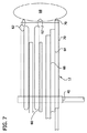
本発明の範囲を逸脱することなく、チューブは他の寸法を有してもよいが、1つの実施形態では、チューブは約1.5cmから約3.0cmの範囲の長さ50を有する。バンド40は、チューブ12を受け入れる突起52を有してもよい。1つの実施形態では、構成部品を一体に固定するために、チューブ12の短い区画(領域)が突起52に鑞付けされる。いくつかの実施形態では、バンド40は、ディストラクタ10を保持し、所定位置に操作するためのハンドル54を有する。チューブ12は、約2.5mmから約3.0mmの範囲の拡張した幅32、および約1.8cmから約2.0cmの範囲の収縮した幅30を有する。すなわちチューブ12は、拡張状態で、収縮した幅30より大きい拡張した幅32を有する。さらに図7に示されるように、拡張した幅は、伸張させた組織を損傷することなく、下方にある組織を修復、除去、外科的処置の実行、照明、吸引、洗浄、可視化、またはそれ以外のためにアクセスするための、器具を受け入れるのに十分な大きさを有する中空の内部24を提供するのに十分広い。そのような器具は、エンドエフェクタ62を有するロボット60のような自動制御装置、内視鏡64のような内視鏡検査装置、および対象領域68内の組織の治療に使用される洗浄管66のような液体処理装置を有してもよい。
Without departing from the scope of the present invention, the tube may have other dimensions, but in one embodiment, the tube has a
図2〜図4に示されるように、1つの実施形態のチューブ12は、拡張状態で略円筒状の形状を有する。さらに、拡張状態にある螺旋状の断面が少なくとも1周するので、ディストラクタ10の外表面20の周囲の組織が外表面と実質的に中断なく接触した状態にあるので、組織が収縮した状態に戻るのを防ぐことができる。この状態はまた、伸張させた(牽引した)組織の負荷を最小化し、損傷を抑制する。
As shown in FIGS. 2 to 4, the
いくつかの実施形態では、ディストラクタは、遠位端部14から近位端部16までチューブ12の中空の内部24を貫通して延びる導管70を有してもよい。1つの実施形態では、チューブ12の形成に使用されるシートは導管70に接合され、導管周辺に巻かれてチューブ状の中空の内部24を形成する。導管を用いて、流体を除去するために対象領域を吸引してもよい。バンド40および導管70を、本発明の範囲から逸脱することなく別の材質で製造してもよいが、1つの実施形態では、これらの構成部品はステンレス鋼で製造される。本発明の範囲から逸脱することなく、導管70を別の方法でシートに取り付けてもよいが、1つの実施形態では、導管はシートに鑞付けされる。チューブ12が脳内に挿入されるとき、導管の端部が脳を損傷するのを防ぐように、湾曲した端部を有する栓塞子72を導管70に挿入してもよいことが想定される。ディストラクタ10が所定位置に配置されると、栓塞子12を取り除き、導管70を用いて対象領域68から流体を吸引してもよい。
In some embodiments, distractors may have a
前述のディストラクタ10を使用して患者の組織を伸張させて、組織の下方にある構造にアクセスするため、外科医はチューブ12の遠位端部14を患者の組織内に導入する。図3Aに示されるように、バンド40は最初に、チューブ12の収縮した幅30に限定するよう調整される。患者の組織内に挿入後、図3Bに示されるように、バンド40はチューブ12の拡張した幅32に限定するよう調整される。外科医は、チューブが患者の組織内に導入されることにより上昇する温度の影響で、チューブ12を拡張させることができる。図4に示されるように拡張させると、外科医は拡張したチューブ12の中空の内部24を通して、患者の組織の下方にある構造にアクセスする。アクセスが必要でなくなった後、外科医は転移温度を下回る温度にチューブ12を冷却して、患者の組織からチューブを取り除く。
By stretching the patient's
1つの実施形態では、本発明のディストラクタ10を、ナビゲーション装置(例えば自動アクチュエータ)で手術プランを生成することにより使用し、望ましくは主要な神経索および皮質の重要な領域を避けて、脳内深くにある異常(例えば病変)にアクセスすることを可能にしてもよい。ディストラクタのハンドル54および/または近位端部16を保持するグリップ装置(図示せず)でディストラクタ10を保持することにより、または、深部の対象68のレベルまで収縮状態にしておき、ディストラクタを手術パスに正確に位置合わせして挿入する自動位置決め装置(図示せず)により、ディストラクタを手術パスに進めることが可能である。所定位置におさまると、バンド40は所望の直径に開く。脳の熱により、その金属部材が拡張状態に戻る。チューブ12が拡張し、脳に均一な圧力を対称的に加え、皮質への損傷を最小化する。
In one embodiment, the
ディストラクタ10が拡張すると、導管70が対象68への手術パスのベースとなる。この位置で、栓塞子72を導管70から取り除き、流体を対象から導管に取り付けられた吸引チューブ(図示せず)に吸引することができる。他の器具を用いて、照明および可視化(例えば、内視鏡64)を実現することができる。このようにして、対象への妨げのない、照明され、および安定したアクセスが実現される。さらに、マイクロ器具を用いて、異常(例えば、病変)を取り除くことができる。例えば、ミクロレベルの誘導および移動が可能なロボット装置60を、手術チャネル(すなわち、中空の内部24)を通して挿入でき、それらの制御部および電源(図示せず)を脳の外側に残すことが可能である。自動装置の制御および電源システムが脳の外側にあり、照明および可視化がディストラクタ10の遠位端部14へ行われるので、制御部および電源は、複数のロボット装置が使用されるときでも、照明および可視化を妨げない位置に配置される。
When the
最終的な開口部の直径は、手術を受ける身体の部分内で自由度を有する装置により切除が実行される場合の対象68の直径より小さくすることができる。手術パスの深部を曲げることで、ディストラクタ10の端部を通して直接的に見える領域を超えて組織を切除することができる。任意の力検出器をディストラクタ20の側面に埋め込み、ディストラクタの側面に及ぼされた力の量を測定することが可能である。脳に対して異なる程度の力が及ぼされた動物の研究での使用を通して、当業者は、神経索および血管の断裂を起こすことなくどれぐらいの力を及ぼすことが可能かを判断することが可能である。従って、力検出器は、ディストラクタにより加えられた力を測定し、過剰な力が脳に加えられた場合にユーザに警告することができる。
The final opening diameter can be smaller than the diameter of the subject 68 when the ablation is performed by a device having a degree of freedom within the body part undergoing surgery. By bending the deep surgical path, it is possible to ablate the tissue beyond the direct manner visible region through the end of the
処置の最後に、手術チャネルを生理食塩水のような冷たい流体で洗浄が可能であり、これで、金属が直径を少なくともわずかに再度減少させる。これは、ディストラクタを取り囲む脳組織から移動させ、脳への付加的な損傷を引き起こすことなく、抜き取りを可能にする。 At the end of the procedure, the surgical channel can be flushed with a cold fluid , such as saline, so that the metal at least slightly reduces the diameter again. It moves from the brain tissue surrounding the distractor, without causing additional damage to the brain, to allow extraction.
図5および図6に示されるように、本発明の手術ディストラクタの第2の実施形態は、通常参照番号110で示される。ディストラクタ110は、通常112で指定する、第1の実施形態のチューブ12と同様のチューブを有する。従って、チューブ112は、転移温度に達したとき、図5に示されるような収縮状態から図6に示されるような拡張状態に拡張する。ディストラクタ110は、チューブ112を通して延びる導管170(図6)も有する。第1の実施形態のように開いた遠位端部を有するよりむしろ、第2の実施形態の導管170は、湾曲した端部キャップ180を有し、ディストラクタ110が挿入されるときに組織への損傷を防ぎ、それによって栓塞子の必要をなくす。湾曲した端部キャップ180は開口部182に囲まれ、第1の実施形態のように、流体を導管170内に注入し、対象から吸引することを可能にする。タブ184が、チューブ112を導管170に取り付けるため、端部キャップ180から延びる。当業者が理解するように、端部キャップ180へのチューブ112の取り付けは、第2の実施形態のディストラクタ110が第1の実施形態のディストラクタ10とほぼ同じように作動することを可能にする。ディストラクタの他の機能は同様であるので、それらはさらに詳述しない。
As shown in FIGS. 5 and 6, the second embodiment of the surgical distractor of the present invention is indicated generally by the
要約すると、本発明の1つのタイプは、深部にある対象への手術アプローチパスの開発を広げる、感熱性ディストラクタ(必ずしも脳への使用に限定されない)を有する。この伸張システムは、近接組織および上部組織の損傷を最小にする一方で、治療(例えば、刺激、薬剤注入、ウィルス注入など)、または身体内の深部の対象組織の切除を可能にする「エンドリスト」(すなわち作業端部への自由度を有する手術アーム)で、ミニチュアロボットを身体の深部で使用することを可能にする。 In summary, one type of the present invention has a thermosensitive distractor (not necessarily limited to brain use) that expands the development of a surgical approach path to a deep subject. The decompression system, while minimizing damage to adjacent tissue and the upper tissue, treatment (e.g., stimulation, drug infusion, virus injection, etc.), or "end list to enable ablation of target tissue deep in the body (Ie, a surgical arm with freedom to the working end), allowing the miniature robot to be used deep in the body.
本発明を詳細に記載したが、添付の請求項に定義された本発明の範囲から逸脱することなく、改良および変形が可能であることが、明らかであろう。 Having described the invention in detail, it will be apparent that modifications and variations are possible without departing from the scope of the invention as defined in the appended claims.
本発明またはその望ましい実施形態の構成要素を紹介するとき、冠詞「1つ」「その」および「前記」は、1つまたは複数の構成要素があることを意味するよう意図される。「備える」、「含む」、および「有する」の語は、包含的であることが意図され、挙げられた構成要素以外の付加的な構成要素があってもよいことを意味する。 When introducing components of the present invention or a preferred embodiment thereof, the articles “one”, “its” and “above” are intended to mean that there are one or more components. The terms “comprising”, “including”, and “having” are intended to be inclusive and mean that there may be additional components other than the listed components.
本発明の範囲から逸脱することなく前述の構造、製品、および方法は種々の変更が可能なので、前記の記載に含まれ、および添付の図に示された全ての事柄は、一例であり、趣旨を限定するものではないと解釈されるべきであることを意図する。 Since various changes may be made in the structure, products, and methods described above without departing from the scope of the present invention, all matters contained in the foregoing description and shown in the accompanying drawings are examples and are intended to Is intended to be construed as not limiting.
Claims (18)
組織内の挿入に適した遠位端部と、前記遠位端部に対向する近位端部と、組織に接触するのに適した外表面と、前記外表面に対向し、前記遠位端部と前記近位端部の間に延びる、組織の下方にある前記構造にアクセスするための中空の内部を形成する内表面とを有するチューブを備え、
前記手術ディストラクタは、前記チューブが前記遠位端部を前記組織内に挿入するための収縮した幅を有する収縮状態と、収縮した幅より大きく、前記中空内部が組織の下方にある構造にある構造にアクセスするのに十分な大きさを有するように拡張した幅を有する拡張状態との間で調節可能であり、
前記手術ディストラクタは、さらにバンドを備え、
前記バンドは、前記チューブの拡張した幅を規制するために前記チューブの前記外表面を包囲する内側表面を有し、
前記バンドは、その周囲の長さを変えて、前記チューブの拡張した幅を調整可能に変えるウォームスクリューおよびラックを有する、
手術ディストラクタ。 A surgical distractor for stretching a patient's tissue to access a structure beneath the patient's tissue,
A distal end suitable for insertion in tissue, a proximal end opposite the distal end, an outer surface suitable for contacting tissue, and opposed to the outer surface, the distal end And a tube having a hollow interior extending between said portion and said proximal end to form a hollow interior for accessing said structure below tissue;
The surgical distractor has a contracted state in which the tube has a contracted width for inserting the distal end portion into the tissue, and a structure in which the hollow interior is larger than the contracted width and the hollow interior is below the tissue. Adjustable between an expanded state having an expanded width to have a sufficient size to access the structure;
The surgical distractor further comprises a band,
The band has an inner surface that surrounds the outer surface of the tube to regulate the expanded width of the tube;
The band has a worm screw and a rack that change its perimeter length to change the expanded width of the tube in an adjustable manner.
Surgery distractor.
螺旋状の断面を有するよう形成されたシートを備え、
前記シートは、組織に接触するのに適した外表面と、前記外表面に対向する、チューブ状の中空の内部を形成する内表面とを有し、
前記螺旋状の断面は、前記組織内に挿入するための収縮した幅を有する収縮状態と、収縮した幅より大きく、前記中空内部が組織の下方にある構造にある構造にアクセスするのに十分な大きさを有するように拡張した幅を有する拡張状態との間で調節可能であり、
前記シートは、転移温度以下に維持されるとき、収縮状態で維持され、転移温度より高い温度に加熱されたとき拡張状態に戻るような形状記憶合金から形成され、
前記手術ディストラクタは、前記シートの拡張した幅を規制するために前記シートを包囲するバンドを有し、
前記バンドは、その周囲の長さを変えて、前記チューブの拡張した幅を調整可能に変えるウォームスクリューおよびラックを有する、
手術ディストラクタ。 A surgical distractor for stretching a patient's tissue to access a structure beneath the patient's tissue,
Comprising a sheet formed to have a spiral cross-section;
The sheet has an outer surface suitable for contact with tissue, and an inner surface that forms a tubular hollow interior facing the outer surface;
The helical cross section is sufficient to access a contracted state having a contracted width for insertion into the tissue and a structure that is larger than the contracted width and wherein the hollow interior is below the tissue. Adjustable between an expanded state with a width expanded to have a size;
The sheet is formed from a shape memory alloy that maintains a contracted state when maintained below the transition temperature and returns to an expanded state when heated to a temperature above the transition temperature;
The surgical distractor has a band surrounding the sheet to regulate the expanded width of the sheet;
The band has a worm screw and a rack that change its perimeter length to change the expanded width of the tube in an adjustable manner.
Surgery distractor.
開口部を含む遠位端部と、前記遠位端部に対向する近位端部とを有し、前記遠位端部および前記近位端部の開口部の間が中空である硬い導管と、
前記導管に接合され、前記導管の周囲に巻かれて螺旋状の断面を有するシートとを備え、
前記シートは、組織に接触するのに適した外表面と、前記外表面に対向する、チューブ状の中空の内部を形成する内表面とを有し、
前記螺旋状の断面は、前記組織内に挿入されるような収縮した幅を有する収縮状態と、収縮した幅より大きく、前記中空内部が組織の下方にある構造にある構造にアクセスできるような拡張した幅を有する拡張状態との間で調節可能であり、
前記シートの拡張した幅を規制するために前記シートを包囲するバンドをさらに備え、
前記バンドは、その周囲の長さを変えて、前記チューブの拡張した幅を調整可能に変えるウォームスクリューおよびラックを有する、
手術ディストラクタ。 A surgical distractor for stretching a patient's tissue to access a structure beneath the patient's tissue,
A rigid conduit having a distal end including an opening and a proximal end opposite the distal end, the hollow being hollow between the distal end and the opening of the proximal end ,
A sheet joined to the conduit and wound around the conduit and having a spiral cross-section;
The sheet has an outer surface suitable for contact with tissue, and an inner surface that forms a tubular hollow interior facing the outer surface;
The spiral cross-section is expanded to allow access to a contracted state with a contracted width to be inserted into the tissue and a structure that is larger than the contracted width and the hollow interior is below the tissue Adjustable between an expanded state having a width
A band surrounding the sheet to regulate an expanded width of the sheet;
The band has a worm screw and a rack that change its perimeter length to change the expanded width of the tube in an adjustable manner.
Surgery distractor.
Applications Claiming Priority (7)
| Application Number | Priority Date | Filing Date | Title |
|---|---|---|---|
| US33304210P | 2010-05-10 | 2010-05-10 | |
| US61/333,042 | 2010-05-10 | ||
| US34933110P | 2010-05-28 | 2010-05-28 | |
| US61/349,331 | 2010-05-28 | ||
| US13/014,473 US8721538B2 (en) | 2010-05-10 | 2011-01-26 | Distractor |
| US13/014,473 | 2011-01-26 | ||
| PCT/US2011/035009 WO2011143011A1 (en) | 2010-05-10 | 2011-05-03 | Distractor |
Publications (3)
| Publication Number | Publication Date |
|---|---|
| JP2013526335A JP2013526335A (en) | 2013-06-24 |
| JP2013526335A5 JP2013526335A5 (en) | 2014-06-19 |
| JP5763177B2 true JP5763177B2 (en) | 2015-08-12 |
Family
ID=44902384
Family Applications (1)
| Application Number | Title | Priority Date | Filing Date |
|---|---|---|---|
| JP2013510137A Expired - Fee Related JP5763177B2 (en) | 2010-05-10 | 2011-05-03 | Distractor |
Country Status (4)
| Country | Link |
|---|---|
| US (1) | US8721538B2 (en) |
| EP (1) | EP2568895A4 (en) |
| JP (1) | JP5763177B2 (en) |
| WO (1) | WO2011143011A1 (en) |
Families Citing this family (11)
| Publication number | Priority date | Publication date | Assignee | Title |
|---|---|---|---|---|
| DE102013205519B4 (en) * | 2013-03-27 | 2019-05-23 | Fehling Instruments Gmbh & Co. Kg | Spreader for the atrium of the heart |
| WO2015138317A1 (en) | 2014-03-10 | 2015-09-17 | Stryker Corporation | Limb positioning system |
| WO2015164591A1 (en) | 2014-04-23 | 2015-10-29 | Applied Medical Resources Corporation | Systems and methods for tissue removal |
| WO2016028789A2 (en) | 2014-08-18 | 2016-02-25 | Applied Medical Resources Corporation | Systems and methods for tissue containment and retrieval |
| EP4248882A3 (en) | 2014-11-13 | 2023-12-06 | Applied Medical Resources Corporation | System for tissue removal |
| US9951904B2 (en) | 2015-03-24 | 2018-04-24 | Stryker Corporation | Rotatable seat clamps for rail clamp |
| EP3285664B1 (en) | 2015-04-23 | 2021-08-04 | Applied Medical Resources Corporation | Systems for tissue removal |
| AU2017209323B2 (en) | 2016-01-22 | 2022-03-10 | Applied Medical Resources Corporaton | Systems and methods for tissue removal |
| US10842371B2 (en) * | 2018-01-25 | 2020-11-24 | Maurice Andre Recanati | Vaginal speculum and side wall retractor |
| JP7235776B2 (en) * | 2018-06-12 | 2023-03-08 | テルモ カーディオバスキュラー システムズ コーポレイション | Circular retractor for cardiovascular valve procedures |
| EP4129203A1 (en) * | 2021-08-06 | 2023-02-08 | Fehling Instruments GmbH&Co. Kg | Surgical retractor for cardiac surgery |
Family Cites Families (38)
| Publication number | Priority date | Publication date | Assignee | Title |
|---|---|---|---|---|
| US2313164A (en) * | 1939-11-13 | 1943-03-09 | Walfred A Nelson | Self-retaining surgical retractor |
| US3030947A (en) * | 1960-05-16 | 1962-04-24 | Richard M Engelbert | Speculum |
| US4411655A (en) | 1981-11-30 | 1983-10-25 | Schreck David M | Apparatus and method for percutaneous catheterization |
| US4921479A (en) * | 1987-10-02 | 1990-05-01 | Joseph Grayzel | Catheter sheath with longitudinal seam |
| US4945896A (en) | 1989-01-24 | 1990-08-07 | Gade George F | Surgical retractor assembly having tissue viability sensor embedded therein |
| GB2240926A (en) * | 1990-02-14 | 1991-08-21 | Steven Streatfield Gill | An expansible cannula |
| US5133720A (en) | 1990-07-13 | 1992-07-28 | Greenberg Alex M | Surgical drill guide and retractor |
| US5147370A (en) | 1991-06-12 | 1992-09-15 | Mcnamara Thomas O | Nitinol stent for hollow body conduits |
| US5284129A (en) | 1992-08-28 | 1994-02-08 | Codman & Shurtleff, Inc. | Swivel ring surgical retractor |
| CA2106236A1 (en) | 1992-09-23 | 1994-03-24 | Jude S. Sauer | Apparatus and method for anchoring surgical instrumentation |
| US5792044A (en) | 1996-03-22 | 1998-08-11 | Danek Medical, Inc. | Devices and methods for percutaneous surgery |
| US6120535A (en) * | 1996-07-29 | 2000-09-19 | Radiance Medical Systems, Inc. | Microporous tubular prosthesis |
| US6102854A (en) | 1997-08-27 | 2000-08-15 | Coroneo Inc. | Sternum retractor for performing bypass surgery on a beating heart |
| US6162172A (en) * | 1998-01-30 | 2000-12-19 | Edwards Lifesciences Corporation | Methods and apparatus for retracting tissue |
| US6106642A (en) | 1998-02-19 | 2000-08-22 | Boston Scientific Limited | Process for the improved ductility of nitinol |
| US6475142B1 (en) | 1999-11-12 | 2002-11-05 | Genzyme Corporation | Curved stabilization arm for use with surgical retractor and tissue stabilization device and methods related thereto |
| US6364833B1 (en) | 1999-01-24 | 2002-04-02 | Genzyme Corpforation | Irrigator for use with surgical retractor and tissue stabilization device and methods related thereto |
| US7056321B2 (en) * | 2000-08-01 | 2006-06-06 | Endius, Incorporated | Method of securing vertebrae |
| US6599240B2 (en) | 2000-12-20 | 2003-07-29 | Genzyme Corporation | Segmented arm assembly for use with a surgical retractor and instruments and methods related thereto |
| FR2824723B1 (en) * | 2001-05-15 | 2003-08-15 | Univ Joseph Fourier | MOUTHPIECE FOR A PHARYNX SENSITIVITY ASSESSMENT DEVICE, DEVICE COMPRISING SAME AND METHOD OF USE |
| US20030069476A1 (en) * | 2001-10-09 | 2003-04-10 | Deslauriers Richard J. | Dilating inflatable speculum |
| US7052454B2 (en) * | 2001-10-20 | 2006-05-30 | Applied Medical Resources Corporation | Sealed surgical access device |
| US6932764B2 (en) * | 2001-11-20 | 2005-08-23 | Ravindra Kashyap | Multipurpose circular retractor |
| US20070270898A1 (en) | 2003-06-20 | 2007-11-22 | Lillehei Kevin O | Surgical Cannula |
| US7226451B2 (en) * | 2003-08-26 | 2007-06-05 | Shluzas Alan E | Minimally invasive access device and method |
| DE602004018342D1 (en) * | 2003-08-26 | 2009-01-22 | Zimmer Spine Inc | ACCESS SYSTEMS FOR MINIMALLY INVASIVE SURGERY |
| WO2005060837A2 (en) * | 2003-12-18 | 2005-07-07 | Depuy Spine, Inc. | Surgical retractor systems, illuminated cannulae, and methods of use |
| US7276047B2 (en) | 2003-12-23 | 2007-10-02 | Cytyc Corporation | Ductal lavage microcatheter with user activated valve and Nitinol introducer |
| US7699864B2 (en) * | 2004-03-18 | 2010-04-20 | Onset Medical Corporation | Expandable medical access device |
| US20060089536A1 (en) * | 2004-10-26 | 2006-04-27 | U.S. Spinal Technologies, Llc | Expandable surgical retractor system for minimal access surgery |
| US20070032703A1 (en) * | 2005-07-11 | 2007-02-08 | Sankaran Meera L | Radially expansive surgical instruments for tissue retraction and methods for using the same |
| EP1752106A1 (en) * | 2005-08-11 | 2007-02-14 | Cardio Life Research S.A. | Surgical retractor |
| EP1959844B1 (en) | 2005-12-15 | 2011-07-20 | Microdel Idea Center Ltd. | Improved radial expansible retractor for minimally invasive surgery |
| US20080058604A1 (en) * | 2006-08-31 | 2008-03-06 | Bradford Tyler Sorensen | Childbirth labor reduction device |
| US20080058605A1 (en) * | 2006-08-31 | 2008-03-06 | Bradford Tyler Sorensen | Tunnel vision gynocological examination device |
| US20080183044A1 (en) | 2007-01-26 | 2008-07-31 | Dennis Colleran | Flexible surgical retractor and method of use |
| US8202216B2 (en) | 2007-03-08 | 2012-06-19 | Warsaw Orthopedic, Inc. | Tissue retractor |
| US8545526B2 (en) * | 2007-12-26 | 2013-10-01 | Lazarus Effect, Inc. | Retrieval systems and methods for use thereof |
-
2011
- 2011-01-26 US US13/014,473 patent/US8721538B2/en not_active Expired - Fee Related
- 2011-05-03 JP JP2013510137A patent/JP5763177B2/en not_active Expired - Fee Related
- 2011-05-03 EP EP11781036.6A patent/EP2568895A4/en not_active Withdrawn
- 2011-05-03 WO PCT/US2011/035009 patent/WO2011143011A1/en active Application Filing
Also Published As
| Publication number | Publication date |
|---|---|
| US20110275902A1 (en) | 2011-11-10 |
| JP2013526335A (en) | 2013-06-24 |
| EP2568895A4 (en) | 2015-03-25 |
| US8721538B2 (en) | 2014-05-13 |
| EP2568895A1 (en) | 2013-03-20 |
| WO2011143011A1 (en) | 2011-11-17 |
Similar Documents
| Publication | Publication Date | Title |
|---|---|---|
| JP5763177B2 (en) | Distractor | |
| JP2013526335A5 (en) | ||
| JP7021211B2 (en) | Medical device | |
| JP3181396U (en) | Device for treating sinusitis | |
| JP5345318B2 (en) | Devices and methods for dilating and modifying sinuses and other intranasal or paranasal cavities | |
| US20180021056A1 (en) | Retractor cannula system for accessing and visualizing spine and related methods | |
| JP5709747B2 (en) | Penetration member with direct visualization | |
| EP1340467B1 (en) | A cavity retaining tool for general surgery | |
| US5100423A (en) | Ablation catheter | |
| US20120065659A1 (en) | Helical groove dilating device and related methods | |
| US20070032703A1 (en) | Radially expansive surgical instruments for tissue retraction and methods for using the same | |
| EP2032061A2 (en) | Directional introducer | |
| US20100125266A1 (en) | Methods and devices to treat compressive neuropathy and other diseases | |
| JP2010518988A (en) | Expandable rotation device and method for tissue aspiration | |
| JP2006511284A (en) | Guide catheter introduced into subarachnoid space and method of using the same | |
| KR20100047870A (en) | Balloon cannula system for accessing and visualizing spine and related methods | |
| JP2007534388A (en) | Apparatus and method for treatment or removal of an intervertebral disc | |
| JP2002506672A (en) | Catheter for delivering energy to the surgical site | |
| WO2007083305A2 (en) | Access enabling device for surgical procedures | |
| JP2008546486A (en) | Expandable surgical site access system | |
| US20040199154A1 (en) | Device for tissue ablation | |
| US9918786B2 (en) | Spinal disk herniation repositioning and radiofrequency ablation (RFA) device and method for treating vertebral disc herniation | |
| US11510662B2 (en) | Free standing bag with integrated cutting guard interface | |
| EP3267909A1 (en) | Manipulating device with tube wall formations | |
| JP6751842B2 (en) | Biological heating equipment |
Legal Events
| Date | Code | Title | Description |
|---|---|---|---|
| A524 | Written submission of copy of amendment under section 19 (pct) |
Free format text: JAPANESE INTERMEDIATE CODE: A524 Effective date: 20140422 |
|
| A621 | Written request for application examination |
Free format text: JAPANESE INTERMEDIATE CODE: A621 Effective date: 20140422 |
|
| A977 | Report on retrieval |
Free format text: JAPANESE INTERMEDIATE CODE: A971007 Effective date: 20141024 |
|
| A131 | Notification of reasons for refusal |
Free format text: JAPANESE INTERMEDIATE CODE: A131 Effective date: 20141028 |
|
| A521 | Written amendment |
Free format text: JAPANESE INTERMEDIATE CODE: A523 Effective date: 20150128 |
|
| TRDD | Decision of grant or rejection written | ||
| A01 | Written decision to grant a patent or to grant a registration (utility model) |
Free format text: JAPANESE INTERMEDIATE CODE: A01 Effective date: 20150512 |
|
| A61 | First payment of annual fees (during grant procedure) |
Free format text: JAPANESE INTERMEDIATE CODE: A61 Effective date: 20150610 |
|
| R150 | Certificate of patent or registration of utility model |
Ref document number: 5763177 Country of ref document: JP Free format text: JAPANESE INTERMEDIATE CODE: R150 |
|
| LAPS | Cancellation because of no payment of annual fees |