JP5762006B2 - Image processing apparatus and image processing method - Google Patents
Image processing apparatus and image processing method Download PDFInfo
- Publication number
- JP5762006B2 JP5762006B2 JP2011005249A JP2011005249A JP5762006B2 JP 5762006 B2 JP5762006 B2 JP 5762006B2 JP 2011005249 A JP2011005249 A JP 2011005249A JP 2011005249 A JP2011005249 A JP 2011005249A JP 5762006 B2 JP5762006 B2 JP 5762006B2
- Authority
- JP
- Japan
- Prior art keywords
- motion vector
- telop
- block
- image
- area
- Prior art date
- Legal status (The legal status is an assumption and is not a legal conclusion. Google has not performed a legal analysis and makes no representation as to the accuracy of the status listed.)
- Expired - Fee Related
Links
Images


Description
本発明は、画像処理装置および画像処理方法に関する。 The present invention relates to an image processing apparatus and an image processing method.
入力された映像信号の時間的に連続する2つのフレーム間の動き情報(動きベクトル)を検出して、それらのフレーム間を補間する補間フレームの画像を生成することで、入力された映像信号のフレームレートを高める技術がある(フレームレート変換処理)。補間フレームの画像を生成する場合には、入力された映像信号の各フレームが複数のブロックに分割され、ブロック毎に動きベクトルが検出される。そして、検出された動きベクトルを用いて補間フレームが生成される。このような技術を用いれば、映像の動きを滑らかに表現することができる。 By detecting motion information (motion vector) between two temporally continuous frames of the input video signal and generating an interpolated frame image that interpolates between those frames, There is a technique for increasing the frame rate (frame rate conversion processing). When generating an image of an interpolation frame, each frame of the input video signal is divided into a plurality of blocks, and a motion vector is detected for each block. Then, an interpolation frame is generated using the detected motion vector. If such a technique is used, the motion of the video can be expressed smoothly.
ところで、映像にテロップが含まれる場合、視聴者はテロップに注目しやすい。そのため、補間フレームの画像を生成してテロップの動きを滑らかに表現することにより、大きな画質向上効果が期待できる。特許文献1には、映像信号からテロップの領域を検出し、テロップの領域に対応するブロックの動きベクトルとして該テロップの動きに基づく動きベクトルを用いて補間フレームの画像を生成する技術が開示されている。特許文献1に開示の技術によれば、テロップの動きを滑らかに表現することができる。
また、動きのある領域の端部分の画質劣化が抑制された補間フレームの画像を生成する技術もある。このような技術は、例えば、特許文献2や特許文献3に開示されている。
By the way, if the video includes a telop, the viewer can easily focus on the telop. Therefore, a large image quality improvement effect can be expected by generating an interpolated frame image and smoothly expressing the motion of the telop. Patent Document 1 discloses a technique for detecting a telop area from a video signal and generating an interpolated frame image using a motion vector based on the motion of the telop as a motion vector of a block corresponding to the telop area. Yes. According to the technique disclosed in Patent Document 1, the movement of a telop can be expressed smoothly.
There is also a technique for generating an image of an interpolated frame in which image quality deterioration at an end portion of a moving region is suppressed. Such a technique is disclosed in Patent Document 2 and Patent Document 3, for example.
しかしながら、テロップの端部分のブロック(端ブロック)では、テロップよりもテロップ以外の部分(以後、背景と呼ぶ)を多く含むことがしばしば生じる。さらに、テロップと背景とでは動きが異なる場合が多い。そのため、端ブロックでは、テロップの動きベクトルが検出されにくく、背景の動きベクトルが検出されやすい。テロップを含むブロックの動きベクトルとして背景の動きベクトルを用いて補間フレームの画像を生成すると、そのブロックでテロップが欠けたように見えてしまう。前述のように、テロップは注目されやすいオブジェクトであるため、テロップが崩れることによる画質の劣化は大きい。 However, a block at the end portion of a telop (end block) often includes a portion other than the telop (hereinafter referred to as background) more than the telop. In addition, there are many cases where the motion is different between the telop and the background. Therefore, in the end block, the motion vector of the telop is difficult to detect, and the background motion vector is easy to detect. When an interpolated frame image is generated using a background motion vector as a motion vector of a block including a telop, the block appears to lack a telop. As described above, since the telop is an object that attracts attention, the image quality is greatly deteriorated due to the collapse of the telop.
本発明は、テロップの領域での画質劣化が抑制された補間フレームの画像を生成することのできる画像処理装置及び画像処理方法を提供することを目的とする。 An object of the present invention is to provide an image processing apparatus and an image processing method capable of generating an interpolated frame image in which image quality deterioration in a telop area is suppressed.
本発明の第1の態様は、入力された映像信号のフレーム間に補間フレームを挿入してフレームレートを変換する画像処理装置であって、入力された映像信号のフレームを複数のブロックに分割し、ブロック毎の動きベクトルを検出する第1動きベクトル検出手段と、入力された映像信号のフレームの少なくとも一部の領域を、前記第1動きベクトル検出手段で分割したブロックよりも小さいブロックである複数の小ブロックに分割し、小ブロック毎の動きベクトルを検出する第2動きベクトル検出手段と、前記第1動きベクトル検出手段で分割したブロックのうち、テロップを含むブロックを検出するテロップ検出手段と、動きベクトルを用いて前記補間フレームの画像を生成する補間フレーム生成手段と、を有し、前記補間フレーム生成手段は、前記テロップを含むブロックのうち、テロップを含まないブロックが隣接するブロックの領域に対して、前記第2動きベクトル検出手段で検出された動きベクトルを用いて補間フレームの画像を生成し、残りのブロックの領域に対して、前記第1動きベクトル検出手段で検出された動きベクトルを用いて補間フレームの画像を生成することを特徴とする画像処理装置である。
A first aspect of the present invention is an image processing apparatus for converting a frame rate by inserting an interpolation frame between frames of an input video signal, and dividing the frame of the input video signal into a plurality of blocks. A first motion vector detecting means for detecting a motion vector for each block; and a plurality of blocks that are smaller than a block obtained by dividing at least a part of a frame of an input video signal by the first motion vector detecting means. A second motion vector detecting means for detecting a motion vector for each small block, and a telop detecting means for detecting a block including a telop among the blocks divided by the first motion vector detecting means, Interpolation frame generation means for generating an image of the interpolation frame using a motion vector, and the interpolation frame generation unit Among the block including the telop, to a region of the block that the block adjacent free of telop, using the motion vector detected by the second motion vector detecting means generates an image of the interpolation frame, the remaining An image processing apparatus is characterized in that an interpolation frame image is generated for the block area using the motion vector detected by the first motion vector detecting means.
本発明の第2の態様は、入力された映像信号のフレーム間に補間フレームを挿入してフレームレートを変換する画像処理装置であって、入力された映像信号のフレームを複数のブロックに分割し、ブロック毎の動きベクトルを検出する動きベクトル検出手段と、前記入力された映像信号に含まれるテロップの動きベクトルの情報を取得する取得手段と、動きベクトルを用いて前記補間フレームの画像を生成する補間フレーム生成手段と、を有し、前記動きベクトル検出手段は、時間的に連続する2つのフレームの一方のフレームのブロック毎に、そのブロック内の画像の画素値との差の絶対値の総和であるSADが最小となる画像の領域を他方のフレームから検出し、前記一方のフレームのブロック毎に、そのブロックと前記検出した領域との位置のずれ量を動きベクトルとして出力するとともに、前記最小となるSADを最小SADとして出力し、前記補間フレーム生成手段は、前記動きベクトル検出手段で検出された動きベクトルが前記取得手段で取得された前記テロップの動きベクトルと等しいブロック及びそのブロックに隣接するブロックのうち、自身の最小SADよりも少なくとも所定値だけ小さい最小SADのブロックが隣接するブロックの領域に対して、前記取得手段で取得された前記テロップの動きベクトルを用いて補間フレームの画像を生成し、残りのブロックの領域に対して、前記動きベクトル検出手段で検出された動きベクトルを用いて補間フレームの画像を生成することを特徴とする画像処理装置である。
According to a second aspect of the present invention, there is provided an image processing device for converting a frame rate by inserting an interpolated frame between frames of an input video signal, and dividing the frame of the input video signal into a plurality of blocks. A motion vector detection unit for detecting a motion vector for each block; an acquisition unit for acquiring information on a motion vector of a telop included in the input video signal; and generating an image of the interpolation frame using the motion vector. Interpolated frame generating means, wherein the motion vector detecting means is a sum of absolute values of differences between pixel values of images in the blocks for each block of one of two temporally continuous frames. A region of the image where SAD is minimum is detected from the other frame, and for each block of the one frame, the block and the detected region The positional deviation amount is output as a motion vector, and the minimum SAD is output as a minimum SAD. The interpolation frame generation means acquires the motion vector detected by the motion vector detection means by the acquisition means. Of the blocks equal to the motion vector of the telop and the blocks adjacent to the block, a block having a minimum SAD that is smaller than the minimum SAD by at least a predetermined value is acquired by the acquisition unit for the adjacent block area. An image of an interpolation frame is generated using the motion vector of the telop, and an image of the interpolation frame is generated using the motion vector detected by the motion vector detection means for the remaining block area. An image processing apparatus.
本発明の第3の態様は、入力された映像信号のフレーム間に補間フレームを挿入してフレームレートを変換する画像処理装置により実行される画像処理方法であって、入力された映像信号のフレームを複数のブロックに分割し、ブロック毎の動きベクトルを検出する第1動きベクトル検出ステップと、入力された映像信号のフレームの少なくとも一部の領域を、前記第1動きベクトル検出ステップで分割したブロックよりも小さいブロックである複数の小ブロックに分割し、小ブロック毎の動きベクトルを検出する第2動きベクトル検出ステップと、前記第1動きベクトル検出ステップで分割したブロックのうち、テロップを含むブロックを検出するテロップ検出ステップと、動きベクトルを用いて前記補間フレームの画像を生成する補間フレーム生成ステップと、を有し、前記補間フレーム生成ステップでは、前記テロップを含むブロックのうち、テロップを含まないブロックが隣接するブロックの領域に対して、前記第2動きベクトル検出ステップで検出された動きベクトルを用いて補間フレームの画像が生成され、残りのブロックの領域に対して、前記第1動きベクトル検出ステップで検出された動きベクトルを用いて補間フレームの画像が生成されることを特徴とする画像処理方法である。
According to a third aspect of the present invention, there is provided an image processing method executed by an image processing device for converting a frame rate by inserting an interpolated frame between frames of an input video signal. Are divided into a plurality of blocks, and a first motion vector detecting step for detecting a motion vector for each block, and a block obtained by dividing at least a partial area of a frame of an input video signal by the first motion vector detecting step. A block including a telop among the blocks divided in the first motion vector detection step, and a second motion vector detection step of detecting a motion vector for each small block, and dividing the block into a plurality of small blocks that are smaller blocks A telop detection step for detecting, and an interpolation frame for generating an image of the interpolation frame using a motion vector. Includes a chromatography beam generating step, a, in the interpolation frame generation step, the blocks including the telop, to a region of the block that the block adjacent free of telop is detected by the second motion vector detection step An image of an interpolation frame is generated using the obtained motion vector, and an image of the interpolation frame is generated using the motion vector detected in the first motion vector detection step for the remaining block area. This is an image processing method.
本発明の第4の態様は、入力された映像信号のフレーム間に補間フレームを挿入してフレームレートを変換する画像処理装置により実行される画像処理方法であって、入力された映像信号のフレームを複数のブロックに分割し、ブロック毎の動きベクトルを検出する動きベクトル検出ステップと、前記入力された映像信号に含まれるテロップの動きベクトルの情報を取得する取得ステップと、動きベクトルを用いて前記補間フレームの画像を生成する補間フレーム生成ステップと、を有し、前記動きベクトル検出ステップでは、時間的に連続する2つのフレームの一方のフレームのブロック毎に、そのブロック内の画像の画素値との差の絶対値の総和であるSADが最小となる画像の領域が他方のフレームから検出され、前記一方のフレームのブロック毎に、そのブロックと前記検出した領域との位置のずれ量が動きベクトルとして出力されるとともに、前記最小となるSADが最小SADとして出力され、前記補間フレーム生成ステップでは、前記動きベクトル検出ステップで検出された動きベクトルが前記取得ステップで取得された前記テロップの動きベクトルと等しいブロック及びそのブロックに隣接するブロックのうち、自身の最小SADよりも少なくとも所定値だけ小さい最小SADのブロックが隣接するブロックの領域に対して、前記取得ステップで取得された前記テロップの動きベクトルを用いて補間フレームの画像が生成され、残りのブロックの領域に対して、前記動きベクトル検出ステップで検出された動きベクトルを用いて補間フレームの画像が生成されることを特徴とする画像処理方法である。 According to a fourth aspect of the present invention, there is provided an image processing method executed by an image processing apparatus for converting a frame rate by inserting an interpolated frame between frames of an input video signal. Is divided into a plurality of blocks, a motion vector detection step for detecting a motion vector for each block, an acquisition step for acquiring motion vector information of a telop included in the input video signal, and the motion vector anda interpolation frame generation step of generating an image of the interpolation frame, and in the motion vector detection step, for each block of one frame of the two temporally successive frames, the pixel values of the image in the block An area of an image in which the SAD, which is the sum of absolute values of the differences between the two frames, is detected from the other frame, and the one frame For each block, the amount of positional deviation between the block and the detected area is output as a motion vector, and the minimum SAD is output as a minimum SAD. In the interpolation frame generation step, the motion vector detection step Among the blocks that are equal to the motion vector of the telop acquired in the acquisition step and the blocks adjacent to the block, the block having the minimum SAD that is smaller than the minimum SAD by at least a predetermined value is adjacent. For a block area, an interpolated frame image is generated using the motion vector of the telop acquired in the acquisition step, and for the remaining block area, the motion vector detected in the motion vector detection step. Can be used to generate an interpolated frame image. Which is the image processing method characterized.
本発明によれば、テロップの領域での画質劣化が抑制された補間フレームの画像を生成することができる According to the present invention, it is possible to generate an interpolated frame image in which image quality deterioration in the telop area is suppressed.
<実施例1>
以下、本発明の実施例1に係る画像処理装置および該装置により実行される画像処理方法について説明する。
本実施例に係る画像処理装置は、入力された映像信号のフレーム間に補間フレームを挿入してフレームレートを変換する。本実施例では、フレームレートが60fpsの映像信号のフレーム間に1枚の補間フレームが挿入され、該映像信号のフレームレートが2倍の120fpsに変換されるものとする。なお、変換前後のフレームレートはこれに限らない。例えば、変換前のフレームレートは120fpsであってもよい。また、フレーム間に2枚以上の補間フレームを挿入してもよい。具体的には、フレーム間に2枚の補間フレームを挿入して、入力された映像信号のフレームレートを3倍のフレームレートに変換してもよい。
また、本実施例では、映像信号がフレーム単位で入力されるものとする。
<Example 1>
Hereinafter, an image processing apparatus according to Embodiment 1 of the present invention and an image processing method executed by the apparatus will be described.
The image processing apparatus according to this embodiment converts the frame rate by inserting an interpolation frame between frames of the input video signal. In this embodiment, it is assumed that one interpolated frame is inserted between frames of a video signal having a frame rate of 60 fps, and the frame rate of the video signal is converted to 120 fps which is doubled. The frame rate before and after conversion is not limited to this. For example, the frame rate before conversion may be 120 fps. Two or more interpolation frames may be inserted between the frames. Specifically, two interpolation frames may be inserted between the frames, and the frame rate of the input video signal may be converted to a triple frame rate.
In this embodiment, it is assumed that a video signal is input in units of frames.
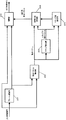
図1は、本実施例に係る画像処理装置の構成を示すブロック図である。
図1において、フレーム遅延部101は、入力された映像信号を1フレーム期間分だけ遅延させて、動きベクトル検出部102、小ブロック動きベクトル検出部103、及び、補間部104に出力する。
FIG. 1 is a block diagram illustrating the configuration of the image processing apparatus according to the present embodiment.
In FIG. 1, the
動きベクトル検出部102は、入力された映像信号のフレームを複数のブロックに分割し、ブロック毎の動きベクトルを検出する。本実施例では、入力された現在のフレーム(現フレーム)と、フレーム遅延部101から取得した1フレーム前のフレーム(前フレーム)との間の動きベクトルが検出される。検出された動きベクトルは、テロップ検出部105、および、補間方法制御部107に出力される。
The motion
以下に、ブロック毎の動きベクトルの検出方法の一例として、ブロックマッチング法について説明する。
ブロックマッチング法では、まず、時間的に連続する2フレーム(現フレームと前フレーム)の一方のフレームの画像がマトリクス状の複数のブロックに分割される。
そして、該複数のブロックのうち1つが注目ブロックとされる。
次に、注目ブロックと最も相関の高い画像の領域が他方のフレームから検出される。
そして、注目ブロックと検出された領域との(相対的な)位置のずれ量が動きベクトルとして検出される。
なお、上記一方のフレームと同様に、上記他方のフレームも複数のブロックに分割してもよい。そして、該複数のブロックから、注目ブロックと最も相関の高いブロックを検出し、注目ブロックと検出されたブロックの位置のずれ量を動きベクトルとして検出してもよい。
Hereinafter, a block matching method will be described as an example of a motion vector detection method for each block.
In the block matching method, first, an image of one frame of two temporally continuous frames (current frame and previous frame) is divided into a plurality of blocks in a matrix form.
One of the plurality of blocks is set as a target block.
Next, the region of the image having the highest correlation with the block of interest is detected from the other frame.
Then, the amount of positional shift between the target block and the detected area is detected as a motion vector.
Note that, similarly to the one frame, the other frame may be divided into a plurality of blocks. Then, a block having the highest correlation with the block of interest may be detected from the plurality of blocks, and a shift amount between the position of the block of interest and the detected block may be detected as a motion vector.
上記相関は、例えば、注目ブロック内の画像の画素値と検出された領域内の画像の画素値との差の絶対値の総和(SAD)によって表される。その場合、上記相関はSADが小さいほど高くなる。即ち、SADが最小となる画像の領域が最も相関の高い画像の領域となる。以後、このようなSAD(最小となるSAD)を最小SADと呼ぶ。
本実施例では、動きベクトル検出部102は、時間的に連続する2フレームの一方のフレームのブロック毎に、SADが最小となる画像の領域を他方のフレームから検出する。そして、一方のフレームのブロック毎に、そのブロックと検出した領域との位置のずれ量を動きベクトルとして出力する。
なお、ブロック毎の動きベクトルの検出方法は、上記方法に限らない。例えば、相関をSAD以外の値で表してもよい。具体的には、相関を注目ブロック内の画像の代表画素値と検出された領域内の画像の代表画素値との差の絶対値で表してもよい。代表画素値は画像の最大値、最小値、平均値、最頻値など、ブロック(領域)を代表する画素値である。また、動きベクトルは勾配法を用いて検出されてもよい。ブロック毎に動きベクトルが検出されればどのような方法を用いてもよい。
The correlation is represented, for example, by the sum of absolute values (SAD) of differences between the pixel values of the image in the block of interest and the pixel values of the image in the detected area. In that case, the correlation increases as the SAD decreases. That is, the image area where the SAD is minimum is the image area having the highest correlation. Hereinafter, such SAD (minimum SAD) is referred to as minimum SAD.
In the present embodiment, the motion
Note that the motion vector detection method for each block is not limited to the above method. For example, the correlation may be expressed by a value other than SAD. Specifically, the correlation may be represented by the absolute value of the difference between the representative pixel value of the image in the target block and the representative pixel value of the image in the detected area. The representative pixel value is a pixel value representing a block (region) such as a maximum value, a minimum value, an average value, or a mode value of an image. The motion vector may be detected using a gradient method. Any method may be used as long as a motion vector is detected for each block.
小ブロック動きベクトル検出部103は、入力された映像信号のフレームの少なくとも一部の領域を、動きベクトル検出部102で分割したブロックよりも小さいブロックである小ブロックに分割し、小ブロック毎の動きベクトル(小ブロック動きベクトル)を検出する。以下、動きベクトル検出部102で分割したブロックは“ブロック”と記載し、小ブロック動きベクトル検出部103で分割したブロックは“小ブロック”と記載する。また、動きベクトル検出部102で検出された動きベクトルは“動きベクトル”と記載し、小ブロック動きベクトル検出部103で検出された動きベクトルは“小ブロック動きベクトル”と記載する。小ブロック動きベクトルは、動きベクトル検出部102と同じ方法(ブロックマッチング法)を用いて検出されてもよいし、動きベクトル検出部102とは異なる方法を用いて検出されてもよい。
The small block motion
本実施例では、小ブロックの大きさを、動きベクトル検出部102で分割したブロックの大きさの4分の1とする。但し、小ブロックの大きさはこれに限らない。小ブロックの大きさは固定値でも、可変値でもよい。また、1フレーム内で小ブロックの大きさは均一でなくてもよい。
例えば、小ブロックの大きさを所定の大きさに設定する。そして、最小SADが十分に小さい小ブロックの領域に対しては、小ブロックの大きさをそのままとする。一方、最小SADが十分に小さくない(所定値以上である)小ブロックの領域に対しては、小ブロックの大きさをより小さくする。それにより、小ブロックの大きさを最適化することができる。この様子を、図3に示す。
また、小ブロック動きベクトル検出部103は、テロップ検出部105よりテロップの動き(動きベクトル)を取得し、小ブロック動きベクトルとして、該テロップの動きベク
トルを、優先的、あるいは、限定的に検出してもよい。
In this embodiment, the size of the small block is set to a quarter of the size of the block divided by the motion
For example, the size of the small block is set to a predetermined size. Then, the size of the small block is left as it is for a small block region having a sufficiently small minimum SAD. On the other hand, for the small block area where the minimum SAD is not sufficiently small (greater than a predetermined value), the size of the small block is made smaller. Thereby, the size of the small block can be optimized. This is shown in FIG.
Further, the small block motion
補間部104は、補間方法制御部107より取得した補間用動きベクトルを用いて補間フレームの画像を生成し(補間フレーム生成処理)、出力する。本実施例では、ブロック毎に、そのブロックの大きさの画像(補間フレームの画像)が生成される。
The
テロップ検出部105は、入力された映像信号からテロップの領域及び該テロップの動きを検出し、検出結果をテロップ端検出部106へ出力する。具体的には、テロップ検出部105は、テロップの領域(テロップ領域)として、動きベクトル検出部102で分割したブロックのうち、テロップを含むブロックを検出する。
テロップの領域とその動きは、例えば、特許文献1に開示されている技術のように、動きベクトルの空間分布を統計的に解析することにより、検出される。但し、テロップの領域とその動きの検出方法はこれに限らない。例えば、入力されたフレームの画像の画素値、フレーム間の画素値の差に関する特徴量、または、その他の付加情報を用いてテロップの領域とその動きが検出されてもよい。テロップの領域は、テロップを含むブロックの集合が検出されれば、どのような方法で検出されてもよい。
The
The telop area and its motion are detected by statistically analyzing the spatial distribution of motion vectors, as in the technique disclosed in Patent Document 1, for example. However, the detection method of the telop area and its movement is not limited to this. For example, the telop area and its motion may be detected using the pixel value of the image of the input frame, the feature amount regarding the difference in pixel value between frames, or other additional information. The telop area may be detected by any method as long as a set of blocks including the telop is detected.
テロップ端検出部106は、テロップ検出部105より取得したテロップ領域の検出結果を用いてテロップの端の領域(テロップ端領域)を検出し、検出結果を補間方法制御部107へ出力する。具体的には、テロップ領域内のブロック(テロップを含むブロック)のうち、テロップを含まないブロックが隣接するブロックの領域をテロップ端領域として検出する。テロップ端領域は、例えば、テロップ領域に相当するブロックでは1を、それ以外のブロックでは0を出力することで、テロップ領域の検出結果を表す2次元の2値データ配列を作成し、作成した2値データ配列に対して一般的なエッジ検出処理を行うなどして検出することができる。但し、テロップ端領域の検出方法は特に限定されない。例えば、テロップ領域内の各ブロックの位置座標を用いて、テロップ領域内のブロックのうちテロップ領域の端に位置するブロック(即ち、テロップ端領域)を検出してもよい。
The telop
補間方法制御部107は、動きベクトル検出部102から動きベクトルを、小ブロック動きベクトル検出部103から小ブロック動きベクトルを、テロップ端検出部106からテロップ端領域の情報を取得する。そして、テロップ端領域内のブロックの補間用動きベクトルとして、小ブロック動きベクトル検出部103から取得した小ブロック動きベクトルを出力する。そして、それ以外のブロックの補間用動きベクトルとして、動きベクトル検出部102から取得した動きベクトルを出力する。
The interpolation
従って、補間部104は、テロップを含むブロックのうち、テロップを含まないブロックが隣接するブロックの領域に対しては、小ブロック動きベクトル検出部103で検出された小ブロック動きベクトルを用いて補間フレームの画像を生成する。即ち、テロップを含むブロックのうち、テロップを含まないブロックが隣接するブロックの領域では、小ブロック毎に補間フレームの画像が生成される。
そして、補間部104は、テロップを含むブロックのうち、残りのブロックの領域に対しては、動きベクトル検出部102で検出された動きベクトルを用いて補間フレームの画像を生成する。即ち、テロップ端領域以外の領域では、動きベクトル検出部102で分割したブロック毎に補間フレームの画像が生成される。
Therefore, the
Then, the
以下、本実施例の効果について説明する。
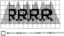
図2は、入力されたフレームの画像の一部の例を示す図である。図2の例では、複数の三角形のオブジェクトを含む静止した背景上を、テロップである文字「RRRR」が右から左へ移動する。図2において、太線で示した範囲内の領域はテロップ領域であり、該領域内のブロックはテロップを含んでいる。また、テロップ領域内のクロスパターン(バツ
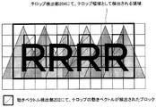
印)を付したブロックはテロップ端領域内のブロックを示している。図4,5は、図2のフレームの次に出力される補間フレームの画像の例を示す図である。なお、図4,5に示す画像の領域は図2の領域と同じ位置、大きさの領域である。
Hereinafter, the effect of the present embodiment will be described.
FIG. 2 is a diagram illustrating an example of a part of an input frame image. In the example of FIG. 2, the text “RRRR” that is a telop moves from right to left on a stationary background including a plurality of triangular objects. In FIG. 2, the area within the range indicated by the bold line is a telop area, and the blocks in the area include the telop. A block with a cross pattern (cross mark) in the telop area indicates a block in the telop edge area. 4 and 5 are diagrams showing examples of images of interpolation frames output next to the frames of FIG. 4 and 5 are regions having the same position and size as the region of FIG.
図4は、補間用動きベクトルとして動きベクトル検出部102で検出された動きベクトルを用いて生成された補間フレームの画像の例である。図2に示したテロップ領域内のブロックのうち、テロップ端領域内のブロックでは、背景の面積がテロップの面積に対して大きくなりやすいため、背景の動きベクトル(本実施例では0(静止))が検出されやすい。一方、テロップ領域内のブロックのうち、テロップ端領域外のブロックでは、テロップの動きベクトルが検出される。そのため、図4の例では、テロップ端領域にテロップの動きベクトルを用いた補間フレーム生成処理が行われないブロックが存在するため、画質が大きく劣化してしまう。
FIG. 4 is an example of an interpolated frame image generated using the motion vector detected by the motion
そこで、本実施例では、テロップ端領域に対しては、小ブロック動きベクトル検出部103で検出された小ブロック動きベクトルを用いて補間フレームの画像を生成する。一方、他の領域に対しては、動きベクトル検出部102で検出された動きベクトルを用いて補間フレームの画像を生成する。
Therefore, in this embodiment, for the telop edge region, an interpolation frame image is generated using the small block motion vector detected by the small block motion
本実施例により生成される補間フレームの画像の例を図5に示す。図5に示すように、テロップ端領域では、図2,4に示すブロックより小さい小ブロック(図2,4の場合の4分の1の大きさのブロック)毎に検出された動きベクトル(小ブロック動きベクトル)を用いて補間フレームの画像が生成される。図2に示すブロックよりも、図5に示す小ブロックの方が1つのブロックに含まれるテロップの面積の割合が大きくなりやすい。そのため、テロップを含む小ブロックでは、図2の場合よりも、テロップの動きベクトルが検出されやすくなる。その結果、図5に示すように、テロップの領域での画質の劣化(テロップの乱れ)が抑制された補間フレームを生成することが可能となる。 An example of an interpolated frame image generated by this embodiment is shown in FIG. As shown in FIG. 5, in the telop edge area, the motion vector (small) detected for each small block smaller than the block shown in FIGS. An image of an interpolation frame is generated using a block motion vector. Compared to the block shown in FIG. 2, the ratio of the area of the telop included in one block is likely to be larger in the small block shown in FIG. For this reason, in a small block including a telop, the motion vector of the telop is more easily detected than in the case of FIG. As a result, as shown in FIG. 5, it is possible to generate an interpolated frame in which image quality deterioration (telop disturbance) in the telop area is suppressed.
以上述べたように、本実施例によれば、テロップ端領域に対しては、小ブロック動きベクトル検出部103で検出された小ブロック動きベクトルを用いて補間フレームの画像が生成される。そして、テロップ領域のうち、テロップ端領域以外の領域に対しては、動きベクトル検出部102で検出された動きベクトルを用いて補間フレームの画像が生成される。そのため、テロップ端領域ではテロップを含むブロックか否かがより細かく判断される。それにより、テロップの端部分でテロップの動きベクトルを用いた補間フレーム生成処理が行われ易くなり、テロップの領域での画質の劣化(テロップの乱れ)が抑制された補間フレームを生成することができる。
As described above, according to the present embodiment, for the telop edge region, an image of an interpolation frame is generated using the small block motion vector detected by the small block motion
また、図2のテロップ領域内全体の動きベクトルをテロップの動きベクトルとして補間フレームを生成すると、テロップの周囲の背景がテロップの動きに引きずられ、画質が劣化する。本実施例によれば、テロップ端領域では、他の領域のブロックよりも小さい小ブロック毎に補間フレームの画像が生成される。そのため、テロップの動きベクトルが補間用動きベクトルとされる背景(テロップ以外の領域)の面積を低減することができ、テロップの周囲の背景がテロップの動きに引きずられることで生じる画質の劣化を低減することができる。
また、本実施例によれば、補間用動きベクトルとして小ブロック動きベクトルが使用されるブロックはテロップ端領域内のブロックに限定される。ブロックマッチングに用いるブロックの大きさを小さくすると、1つのブロックに含まれる情報量が少なくなるため、動きベクトルの誤検出が生じやすくなる。動きベクトルの誤検出は、画質の劣化をまねく。例えば、図2のテロップ領域全体に対して小ブロック動きベクトルを用いた補間フレーム生成処理を行うと、テロップ端部の画質が改善されたとしても、テロップ端部以外のブロックで動きベクトルの誤検出が生じ、図4の場合よりも画質が劣化する虞がある。本実
施例では、小ブロック動きベクトルを用いた補間フレーム生成処理はテロップ端領域に限定されるため、動きベクトルの誤検出を抑制することができ、ひいてはテロップの画質の劣化を抑制することができる。
Also, when an interpolated frame is generated using the entire motion vector in the telop area of FIG. 2 as the telop motion vector, the background around the telop is dragged by the telop motion, and the image quality deteriorates. According to the present embodiment, in the telop edge area, an image of an interpolation frame is generated for each small block smaller than the blocks in other areas. Therefore, it is possible to reduce the area of the background (region other than the telop) in which the telop motion vector is the motion vector for interpolation, and to reduce image quality degradation caused by the background around the telop being dragged by the motion of the telop. can do.
Further, according to the present embodiment, the blocks in which the small block motion vector is used as the interpolation motion vector are limited to the blocks in the telop edge region. If the size of the block used for block matching is reduced, the amount of information contained in one block is reduced, so that erroneous detection of motion vectors is likely to occur. An erroneous detection of a motion vector leads to degradation of image quality. For example, if interpolation frame generation processing using small block motion vectors is performed on the entire telop area in FIG. 2, even if the image quality at the telop edge is improved, motion vectors are erroneously detected in blocks other than the telop edge. As a result, the image quality may be deteriorated as compared with the case of FIG. In this embodiment, the interpolation frame generation process using the small block motion vector is limited to the telop edge region, so that it is possible to suppress erroneous detection of the motion vector and, in turn, deterioration of the image quality of the telop. .
なお、本実施例では、ブロック毎に、補間用動きベクトルが、小ブロック動きベクトル検出部103から取得した小ブロック動きベクトルと、動きベクトル検出部102から取得した動きベクトルとの間で切り替えられるが、本発明はこの構成に限らない。
例えば、補間部104は、小ブロック動きベクトル検出部103で検出された小ブロック動きベクトルを用いて第1の(補間フレームの)画像を生成し、動きベクトル検出部102で検出された動きベクトルを用いて第2の(補間フレームの)画像を生成してもよい。そして、補間部104は、テロップを含まないブロックが隣接するブロックの領域と他の領域との境界部では、第1の画像と第2の画像を合成して最終的な補間フレームの画像を生成してもよい。このような構成にすることにより、テロップ端領域を境界として、テロップ領域とその他の領域との間で急激に画像処理(動きベクトル)が変化することに起因して生じる違和感を低減できる。
In this embodiment, for each block, the interpolation motion vector is switched between the small block motion vector acquired from the small block motion
For example, the
なお、上述したように、小ブロック動きベクトル検出部103で分割した小ブロックでは、動きベクトル検出部102で分割したブロックよりも、テロップの動きベクトルが検出されやすい。そこで、境界部では、テロップ領域の内側に向かうにつれて第1画像の重みが大きくなるように、第1画像と第2画像を重み付け合成するとよい。
なお、上記境界部は、テロップ端領域全体であってもよいし、テロップ端領域の一部(例えば、テロップを含まないブロックが隣接する小ブロックの領域)であってもよい。また、上記境界部は、テロップ端領域の周囲の領域、例えば、テロップ端領域から所定範囲内にあるテロップを含まないブロックの領域、テロップを含むブロックの領域、または、それら両方の領域を含んでいてもよい。上記効果が得られれば、境界部はどのように定義されてもよい。
As described above, in the small block divided by the small block motion
The boundary portion may be the entire telop edge area or a part of the telop edge area (for example, a small block area adjacent to a block not including the telop). The boundary includes an area around the telop edge area, for example, an area of a block that does not include a telop within a predetermined range from the telop edge area, an area of a block that includes the telop, or both areas. May be. The boundary may be defined in any way as long as the above effect is obtained.
また、補間部104は、境界部では、小ブロック動きベクトル検出部103で検出された小ブロック動きベクトルと動きベクトル検出部102で検出された動きベクトルとを合成した動きベクトルを用いて補間フレームの画像を生成してもよい。そのような構成であっても、上記効果と同様の効果を得ることができる。
In addition, the
なお、小ブロック動きベクトル検出部103は、フレームの画像全体を複数の小ブロックに分割してもよいし、フレームの一部の領域(例えば、テロップ端領域のみ)を複数の小ブロックに分割してもよい。小ブロック動きベクトルを検出する領域を小さくすれば(例えば、小ブロック動きベクトルを検出する領域をテロップ端領域のみに制限すれば)、小ブロック動きベクトルを検出する処理の負荷を軽減することができる。また、上述した動きベクトルの誤検出を抑制することができる。
なお、“隣接する”とは、斜め方向に隣接することを含んでいてもよいし、水平方向と垂直方向に隣接することに限定されてもよい。
Note that the small block motion
Note that “adjacent” may include being adjacent in an oblique direction, and may be limited to being adjacent in the horizontal direction and the vertical direction.
<実施例2>
以下、本発明の実施例2に係る画像処理装置および該装置により実行される画像処理方法について説明する。
図6は本実施例に係る画像処理装置の構成を示すブロック図である。
<Example 2>
Hereinafter, an image processing apparatus according to Embodiment 2 of the present invention and an image processing method executed by the apparatus will be described.
FIG. 6 is a block diagram illustrating the configuration of the image processing apparatus according to the present embodiment.
図6において、フレーム遅延部201は、入力された映像信号を1フレーム期間分だけ遅延させて、動きベクトル検出部202、補間部203に出力する。
動きベクトル検出部202は、入力された映像信号の各フレームを複数のブロックに分割し、ブロック毎の動きベクトルを検出する。具体的には、動きベクトル検出部202は
、時間的に連続する2フレームの一方のフレームのブロック毎に、SADが最小となる画像の領域を他方のフレームから検出する。そして、一方のフレームのブロック毎に、そのブロックと検出した領域との位置のずれ量を動きベクトルとして出力するとともに、上記最小となるSADを最小SADとして出力する。なお、動きベクトルと最小SADは、テロップ検出部204、テロップ端検出部205、および、補間方法制御部206に出力される。
補間部203は、補間方法制御部206より取得した補間用動きベクトルを用いて補間フレームの画像を生成し(補間フレーム生成処理)、出力する。
In FIG. 6, the
The motion
The
テロップ検出部204は、入力された映像信号に含まれるテロップの動きベクトルの情報を取得する。本実施例では、入力された映像信号からテロップの領域及び該テロップの動き(動きベクトル)を検出する。検出結果はテロップ端検出部205へ出力される。
具体的には、テロップ検出部204は、動きベクトル検出部202より取得した動きベクトルのヒストグラムを生成する。
次に、テロップ検出部204は、ヒストグラムの水平または垂直方向の動きベクトルに相当するカテゴリの度数が所定数以上である場合、そのカテゴリの動きベクトルをテロップの動きベクトルとして検出する。なお、度数が所定数以上となる水平または垂直方向のベクトルのカテゴリに、大きさの異なる複数の動きベクトルが属す場合には、該カテゴリに属す動きベクトルの大きさの代表値をテロップの動きベクトルの大きさとすればよい。代表値は、例えば、最大値、最小値、平均値、最頻値などである。
そして、テロップ検出部204は、動きベクトル検出部202で検出された動きベクトルが上記検出したテロップの動きベクトルと等しいブロックの領域を、テロップの領域として検出する。なお、動きベクトル検出部202で検出された動きベクトルとテロップ検出部204で検出されたテロップの動きベクトルは完全に一致していなくてもよい。即ち、誤差を考慮してテロップの領域が検出されてもよい。
テロップ検出部204は、さらに、テロップの端では背景の動きベクトルが検出されていることを想定し、上記テロップの領域としたブロックに隣接するブロックもテロップの領域とする。即ち、本実施例では、動きベクトル検出部202で検出された動きベクトルがテロップ検出部204で取得されたテロップの動きベクトルと等しいブロック及びそのブロックに隣接するブロックの領域がテロップ領域とされる。
なお、テロップの領域およびその動きの検出方法はこれに限らない。テロップの領域やテロップの動きベクトルの情報は、外部から取得されてもよい。テロップの領域やテロップの動きベクトルの情報は、メタデータとして映像信号に付加されていてもよい。
The
Specifically, the
Next, when the frequency of the category corresponding to the horizontal or vertical motion vector of the histogram is equal to or greater than a predetermined number, the
Then, the
Further, the
Note that the telop area and its motion detection method are not limited thereto. Information on the telop area and the motion vector of the telop may be acquired from the outside. Information on the telop area and the motion vector of the telop may be added to the video signal as metadata.
テロップ端検出部205は、動きベクトル検出部202から取得した最小SADと、テロップ検出部204の出力と用いてテロップ端領域を検出し、検出結果を補間方法制御部206に出力する。具体的には、テロップ領域内のブロックのうち、自身の最小SADよりも少なくとも所定値だけ小さい最小SADのブロックが隣接するブロックの領域をテロップ端領域として検出する。
The telop
補間方法制御部206は、動きベクトル検出部202から動きベクトルを、テロップ検出部204からテロップの動きベクトルを、テロップ端検出部205からテロップ端領域の情報を取得する。そして、テロップ端領域内のブロックの補間用動きベクトルとして、テロップ検出部204から取得したテロップの動きベクトルを出力する。そして、それ以外のブロックの補間用動きベクトルとして、動きベクトル検出部202から取得した動きベクトルを出力する。
The interpolation
従って、補間部203は、テロップ領域内のブロックのうち、テロップ端領域内のブロックに対して、テロップ検出部204で取得されたテロップの動きベクトルを用いて補間フレームの画像を生成する。
そして、補間部203は、テロップ領域内のブロックのうち、残りのブロックの領域に対して、動きベクトル検出部202で検出された動きベクトルを用いて補間フレームの画像を生成する
Therefore, the
Then, the
以下、本実施例の作用効果について説明する。
図7は、入力されたフレームの画像の一部の例を示す図である。図7に示すように、本実施例では、動きベクトル検出部202で検出された動きベクトルがテロップ検出部204で取得されたテロップの動きベクトルと等しいブロック及びそのブロックに隣接するブロックの領域がテロップ領域とされる。このような構成の場合、図7に示すように、テロップ領域が、テロップを含むブロックからなる領域よりも大きくなってしまうことがある。即ち、テロップ領域にテロップを含まない(背景のみを含む)ブロックの領域が含まれることがある。このようなテロップ領域に対し実施例1と同じ方法でテロップ端領域を検出すると、背景のみを含むブロックがテロップ端領域とされ、テロップの周囲の背景がテロップの動きに引きずられることによる妨害が大きくなる虞がある。逆に、テロップの動きベクトルが検出されたブロックのみをテロップ領域として検出すると、テロップ領域が、テロップが含まれるブロックからなる領域よりも小さくなってしまうことがある。このように検出されたテロップ領域に対し実施例1と同じ方法でテロップ端領域を検出すると、テロップの端部分(テロップを含むブロック)で背景の動きベクトルを用いた補間フレーム生成処理が行われ、期待した画質改善効果が得られない。
Hereinafter, the effect of the present embodiment will be described.
FIG. 7 is a diagram illustrating an example of a part of an input frame image. As shown in FIG. 7, in this embodiment, a block in which the motion vector detected by the motion
そこで、本実施例では最小SADを分析して、テロップ端領域を精度良く検出する。
図7のフレームが入力されたときの各ブロックの最小SADの例を図8に示す。
テロップを含まない(背景の)ブロックは最小SADが0となっている。これは、該ブロックでは、フレーム間で完全なマッチングが取れており、非常に高い相関が得られていることを意味する。
一方、テロップが含まれるブロックの最小SADは、背景のブロックと比較して大きな値になっている(図8の例では、300)。これは、背景のブロックと比較して、テロップが含まれるブロックではフレーム間の相関が低いことを意味する。テロップが含まれるブロックではテロップ(前景)と背景が混在しており、かつ、それらの動きが異なるため、テロップと背景との相対的な位置関係がフレーム毎に変化する。また、テロップ(前景)が移動することにより、あるフレームではテロップの下に隠れていた背景が次のフレームで出現したり、逆に見えていた背景が次のフレームではテロップで隠れたりする。そのため、テロップが含まれるブロックではフレーム間の相関が低下し、背景のブロックと比べて最小SADが大きくなる。
Therefore, in this embodiment, the minimum SAD is analyzed to detect the telop edge region with high accuracy.
An example of the minimum SAD of each block when the frame of FIG. 7 is input is shown in FIG.
A block that does not include a telop (background) has a minimum SAD of zero. This means that in the block, perfect matching is obtained between frames, and a very high correlation is obtained.
On the other hand, the minimum SAD of the block including the telop is larger than that of the background block (300 in the example of FIG. 8). This means that the correlation between frames is lower in a block including a telop than in a background block. In a block including a telop, a telop (foreground) and a background are mixed and their movements are different, so that the relative positional relationship between the telop and the background changes for each frame. Also, by moving the telop (foreground), the background that was hidden under the telop in one frame appears in the next frame, or the background that was viewed in reverse is hidden in the telop in the next frame. Therefore, the correlation between frames is reduced in a block including a telop, and the minimum SAD is increased as compared with the background block.
テロップの端のブロックには、背景のブロックが隣接していると考えられる。即ち、テロップの端のブロックには、自身の最小SADよりも少なくとも所定値だけ小さい最小SADのブロックが隣接していると考えられる。
そこで、本実施例では、テロップ領域内のブロックのうち、自身の最小SADよりも少なくとも所定値だけ小さい最小SADのブロックが隣接するブロックの領域をテロップ端領域として検出する。これにより、テロップ端領域を精度良く検出できる。
そして、テロップ端領域に対しては、テロップ検出部204で取得されたテロップの動きベクトルを用いて補間フレーム生成処理が行われ、その他の領域に対しては、動きベクトル検出部202で検出された動きベクトルを用いて補間フレーム生成処理が行われる。
それにより、図9に示すように、テロップを含むブロックの領域に対しテロップの動きベクトルを用いた補間フレーム生成処理が行われ、テロップの領域での画質の劣化が抑制できる。
It is considered that the background block is adjacent to the block at the end of the telop. In other words, the block at the end of the telop is considered to be adjacent to a block having a minimum SAD that is at least a predetermined value smaller than its own minimum SAD.
Therefore, in the present embodiment, among the blocks in the telop area, the area of the block adjacent to the minimum SAD block that is at least a predetermined value smaller than its own minimum SAD is detected as the telop end area. Thereby, the telop edge region can be detected with high accuracy.
The telop edge region is subjected to interpolation frame generation processing using the telop motion vector acquired by the
As a result, as shown in FIG. 9, the interpolation frame generation processing using the motion vector of the telop is performed on the block area including the telop, and the deterioration of the image quality in the telop area can be suppressed.
以上述べたように、本実施例によれば、動きベクトル検出部202で検出された動きベクトルがテロップ検出部204で取得されたテロップの動きベクトルと等しいブロック及
びそのブロックに隣接するブロックの領域がテロップ領域とされる。そして、テロップ領域内のブロックのうち、自身の最小SADよりも少なくとも所定値だけ小さい最小SADのブロックが隣接するブロックの領域がテロップ端領域とされる。それにより、テロップ端領域を精度よく検出することができる。
また、テロップ端領域に対して、テロップ検出部204で取得されたテロップの動きベクトルを用いて補間フレームの画像が生成される。テロップ領域のうち、テロップ端領域以外の領域に対して、動きベクトル検出部202で検出された動きベクトルを用いて補間フレームの画像が生成される。それにより、テロップを含むブロックの領域に対してテロップの動きベクトルを用いた補間フレーム生成処理を行うことができ、テロップの領域での画質の劣化が抑制できる。
As described above, according to the present embodiment, a block in which the motion vector detected by the motion
An interpolation frame image is generated for the telop edge region using the telop motion vector acquired by the
なお、本実施例では、ブロック毎に、補間用動きベクトルが、テロップ検出部204から取得したテロップの動きベクトルと、動きベクトル検出部202から取得した動きベクトルとの間で切り替えられるが、本発明はこの構成に限らない。
例えば、補間部203は、テロップ検出部204で取得されたテロップの動きベクトルを用いて第1の(補間フレームの)画像を生成し、動きベクトル検出部202で検出された動きベクトルを用いて第2の(補間フレームの)画像を生成してもよい。そして、補間部203は、自身の最小SADよりも少なくとも所定値だけ小さい最小SADのブロックが隣接するブロックの領域と他の領域との境界部では、第1の画像と第2の画像を合成して最終的な補間フレームの画像を生成してもよい。このような構成にすることにより、テロップ端領域を境界として、テロップ領域とその他の領域との間で急激に画像処理(動きベクトル)が変化することに起因して生じる違和感を低減できる。
In this embodiment, the interpolation motion vector is switched between the telop motion vector acquired from the
For example, the
具体的には、境界部では、テロップ領域の内側に向かうにつれて第1画像の重みが大きくなるように、第1画像と第2画像を重み付け合成するとよい。
なお、上記境界部は、テロップ端領域であってもよいし、テロップ端領域以外の領域であってもよい。上記境界部は、テロップ端領域の周囲の領域、例えば、テロップ端領域から所定範囲内にあるテロップを含まないブロックの領域、テロップを含むブロックの領域、または、それら両方の領域を含んでいてもよい。上記効果が得られれば、境界部はどのように定義されてもよい。
Specifically, at the boundary portion, the first image and the second image may be weighted and synthesized so that the weight of the first image increases toward the inside of the telop area.
The boundary part may be a telop edge area or an area other than the telop edge area. The boundary portion may include an area around the telop edge area, for example, an area of a block not including a telop within a predetermined range from the telop edge area, an area of a block including the telop, or both areas. Good. The boundary may be defined in any way as long as the above effect is obtained.
また、補間部104は、境界部では、テロップ検出部204で取得されたテロップの動きベクトルと動きベクトル検出部202で検出された動きベクトルとを合成した動きベクトルを用いて補間フレームの画像を生成してもよい。そのような構成であっても、上記効果と同様の効果を得ることができる。
In addition, the
102 動きベクトル検出部
103 小ブロック動きベクトル検出部
104 補間部
105 テロップ検出部
202 動きベクトル検出部
203 補間部
204 テロップ検出部
102 motion
Claims (6)
入力された映像信号のフレームを複数のブロックに分割し、ブロック毎の動きベクトルを検出する第1動きベクトル検出手段と、
入力された映像信号のフレームの少なくとも一部の領域を、前記第1動きベクトル検出手段で分割したブロックよりも小さいブロックである複数の小ブロックに分割し、小ブロック毎の動きベクトルを検出する第2動きベクトル検出手段と、
前記第1動きベクトル検出手段で分割したブロックのうち、テロップを含むブロックを検出するテロップ検出手段と、
動きベクトルを用いて前記補間フレームの画像を生成する補間フレーム生成手段と、
を有し、
前記補間フレーム生成手段は、前記テロップを含むブロックのうち、
テロップを含まないブロックが隣接するブロックの領域に対して、前記第2動きベクトル検出手段で検出された動きベクトルを用いて補間フレームの画像を生成し、
残りのブロックの領域に対して、前記第1動きベクトル検出手段で検出された動きベクトルを用いて補間フレームの画像を生成する
ことを特徴とする画像処理装置。 An image processing apparatus for converting a frame rate by inserting an interpolation frame between frames of an input video signal,
First motion vector detection means for dividing a frame of an input video signal into a plurality of blocks and detecting a motion vector for each block;
The at least part of the frame of the input video signal is divided into a plurality of small blocks that are smaller than the blocks divided by the first motion vector detecting means, and a motion vector for each small block is detected. Two motion vector detection means;
A telop detection means for detecting a block including a telop among the blocks divided by the first motion vector detection means;
Interpolation frame generation means for generating an image of the interpolation frame using a motion vector;
Have
The interpolation frame generation means includes a block including the telop.
For an area of a block adjacent to a block that does not include a telop, an interpolation frame image is generated using the motion vector detected by the second motion vector detection unit,
An image processing apparatus for generating an interpolated frame image for the remaining block area using the motion vector detected by the first motion vector detecting means.
ことを特徴とする請求項1に記載の画像処理装置。 The interpolation frame generation means includes an image generated using the motion vector detected by the second motion vector detection means at a boundary portion between a block area adjacent to the block not including the telop and another area, and the image An image generated using the motion vector detected by the first motion vector detection means is synthesized, or the motion vector detected by the second motion vector detection means and the first motion vector detection means are detected. The image processing apparatus according to claim 1, wherein an image of the interpolation frame is generated by using a motion vector synthesized with a motion vector.
ことを特徴とする請求項1または2に記載の画像処理装置。 3. The second motion vector detecting means divides only a block area adjacent to a block not including a telop among the blocks including the telop into the plurality of small blocks. Image processing apparatus.
入力された映像信号のフレームを複数のブロックに分割し、ブロック毎の動きベクトルを検出する第1動きベクトル検出ステップと、
入力された映像信号のフレームの少なくとも一部の領域を、前記第1動きベクトル検出ステップで分割したブロックよりも小さいブロックである複数の小ブロックに分割し、小ブロック毎の動きベクトルを検出する第2動きベクトル検出ステップと、
前記第1動きベクトル検出ステップで分割したブロックのうち、テロップを含むブロックを検出するテロップ検出ステップと、
動きベクトルを用いて前記補間フレームの画像を生成する補間フレーム生成ステップと、
を有し、
前記補間フレーム生成ステップでは、前記テロップを含むブロックのうち、
テロップを含まないブロックが隣接するブロックの領域に対して、前記第2動きベクトル検出ステップで検出された動きベクトルを用いて補間フレームの画像が生成され、
残りのブロックの領域に対して、前記第1動きベクトル検出ステップで検出された動きベクトルを用いて補間フレームの画像が生成される
ことを特徴とする画像処理方法。 An image processing method executed by an image processing apparatus for converting a frame rate by inserting an interpolation frame between frames of an input video signal,
A first motion vector detection step of dividing a frame of the input video signal into a plurality of blocks and detecting a motion vector for each block;
First, a region of at least a part of the frame of the input video signal is divided into a plurality of small blocks that are smaller than the block divided in the first motion vector detection step, and a motion vector for each small block is detected. Two motion vector detection steps;
A telop detection step of detecting a block including a telop among the blocks divided in the first motion vector detection step;
An interpolation frame generation step of generating an image of the interpolation frame using a motion vector;
Have
In the interpolation frame generation step, among the blocks including the telop,
An interpolated frame image is generated using the motion vector detected in the second motion vector detection step for an area of a block adjacent to a block not including a telop,
An image processing method, wherein an image of an interpolation frame is generated for the remaining block area using the motion vector detected in the first motion vector detection step.
ことを特徴とする請求項4に記載の画像処理方法。 In the interpolation frame generation step, an image generated using the motion vector detected in the second motion vector detection step at a boundary portion between a block area adjacent to the block not including the telop and another area, and the block The image generated using the motion vector detected in the first motion vector detection step is synthesized, or the motion vector detected in the second motion vector detection step and the motion vector detected in the first motion vector detection step The image processing method according to claim 4 , wherein an image of the interpolation frame is generated by using a motion vector synthesized with a motion vector.
ことを特徴とする請求項4または5に記載の画像処理方法。 The said 2nd motion vector detection step WHEREIN: Only the area | region of the block which the block which does not contain a telop among the blocks which contain the said telop is adjacent is divided | segmented into these several small blocks, The Claim 4 or 5 characterized by the above-mentioned. The image processing method as described.
Priority Applications (1)
| Application Number | Priority Date | Filing Date | Title |
|---|---|---|---|
| JP2011005249A JP5762006B2 (en) | 2011-01-13 | 2011-01-13 | Image processing apparatus and image processing method |
Applications Claiming Priority (1)
| Application Number | Priority Date | Filing Date | Title |
|---|---|---|---|
| JP2011005249A JP5762006B2 (en) | 2011-01-13 | 2011-01-13 | Image processing apparatus and image processing method |
Publications (3)
| Publication Number | Publication Date |
|---|---|
| JP2012147336A JP2012147336A (en) | 2012-08-02 |
| JP2012147336A5 JP2012147336A5 (en) | 2014-02-27 |
| JP5762006B2 true JP5762006B2 (en) | 2015-08-12 |
Family
ID=46790423
Family Applications (1)
| Application Number | Title | Priority Date | Filing Date |
|---|---|---|---|
| JP2011005249A Expired - Fee Related JP5762006B2 (en) | 2011-01-13 | 2011-01-13 | Image processing apparatus and image processing method |
Country Status (1)
| Country | Link |
|---|---|
| JP (1) | JP5762006B2 (en) |
Families Citing this family (1)
| Publication number | Priority date | Publication date | Assignee | Title |
|---|---|---|---|---|
| KR101541077B1 (en) * | 2014-04-07 | 2015-07-31 | 아주대학교산학협력단 | Device and method for frame interpolation using block segmentation based on texture |
Family Cites Families (4)
| Publication number | Priority date | Publication date | Assignee | Title |
|---|---|---|---|---|
| JP3576618B2 (en) * | 1995-01-04 | 2004-10-13 | 日本放送協会 | Motion vector detection method and apparatus |
| JP2009055340A (en) * | 2007-08-27 | 2009-03-12 | Sharp Corp | Image display device and method, and image processing apparatus and method |
| JP4309453B2 (en) * | 2007-12-26 | 2009-08-05 | 株式会社東芝 | Interpolated frame generating apparatus, interpolated frame generating method, and broadcast receiving apparatus |
| JP2010098513A (en) * | 2008-10-16 | 2010-04-30 | Toshiba Corp | Apparatus and method for generating interpolated image |
-
2011
- 2011-01-13 JP JP2011005249A patent/JP5762006B2/en not_active Expired - Fee Related
Also Published As
| Publication number | Publication date |
|---|---|
| JP2012147336A (en) | 2012-08-02 |
Similar Documents
| Publication | Publication Date | Title |
|---|---|---|
| JP5687553B2 (en) | Image composition apparatus, image composition method, and image composition program | |
| JP5777311B2 (en) | How to generate high-resolution video from low-resolution video | |
| JP4375080B2 (en) | Image processing apparatus and method, recording medium, and program | |
| US20100123792A1 (en) | Image processing device, image processing method and program | |
| JP2003259374A (en) | Apparatus for and method of transforming scanning format | |
| US8675128B2 (en) | Image processing method and system with repetitive pattern detection | |
| JP2006287632A (en) | Noise reducer and noise reducing method | |
| US8615036B2 (en) | Generating interpolated frame of video signal with enhancement filter | |
| JPWO2009119347A1 (en) | Processing system, image processing method, and image processing program | |
| JP2012034327A5 (en) | ||
| US8836860B2 (en) | Method and apparatus for converting image rate by using image scaling | |
| US8213736B2 (en) | Image processing device and image processing method | |
| JP2008148315A (en) | Method and apparatus for reconstructing image | |
| JP2010081411A (en) | Frame interpolation device and frame interpolation method | |
| JP5192087B2 (en) | Image processing apparatus and image processing method | |
| JP4552691B2 (en) | Moving picture conversion apparatus, moving picture restoration apparatus and method, and computer program | |
| US9106926B1 (en) | Using double confirmation of motion vectors to determine occluded regions in images | |
| JP5762006B2 (en) | Image processing apparatus and image processing method | |
| JP5448983B2 (en) | Resolution conversion apparatus and method, scanning line interpolation apparatus and method, and video display apparatus and method | |
| JP2009157449A (en) | Image processing system, image processing method, and program for image processing | |
| JP5435242B2 (en) | Image processing method, image processing apparatus, and image processing program | |
| JP5400655B2 (en) | Image processing apparatus, image processing method, image processing program, and electronic apparatus | |
| JP4712495B2 (en) | Scan conversion device and program | |
| JP2004147281A (en) | Special video effect creation apparatus, special video effect creation method, and special video effect creation program | |
| JP2014033357A (en) | Video signal processor and video signal processing method |
Legal Events
| Date | Code | Title | Description |
|---|---|---|---|
| A521 | Written amendment |
Free format text: JAPANESE INTERMEDIATE CODE: A523 Effective date: 20140109 |
|
| A621 | Written request for application examination |
Free format text: JAPANESE INTERMEDIATE CODE: A621 Effective date: 20140109 |
|
| A977 | Report on retrieval |
Free format text: JAPANESE INTERMEDIATE CODE: A971007 Effective date: 20141028 |
|
| A131 | Notification of reasons for refusal |
Free format text: JAPANESE INTERMEDIATE CODE: A131 Effective date: 20141104 |
|
| A521 | Written amendment |
Free format text: JAPANESE INTERMEDIATE CODE: A523 Effective date: 20141202 |
|
| TRDD | Decision of grant or rejection written | ||
| A01 | Written decision to grant a patent or to grant a registration (utility model) |
Free format text: JAPANESE INTERMEDIATE CODE: A01 Effective date: 20150512 |
|
| A61 | First payment of annual fees (during grant procedure) |
Free format text: JAPANESE INTERMEDIATE CODE: A61 Effective date: 20150609 |
|
| R151 | Written notification of patent or utility model registration |
Ref document number: 5762006 Country of ref document: JP Free format text: JAPANESE INTERMEDIATE CODE: R151 |
|
| LAPS | Cancellation because of no payment of annual fees |