JP5761803B2 - Self-cleaning tank type membrane filtration device - Google Patents
Self-cleaning tank type membrane filtration device Download PDFInfo
- Publication number
- JP5761803B2 JP5761803B2 JP2011272104A JP2011272104A JP5761803B2 JP 5761803 B2 JP5761803 B2 JP 5761803B2 JP 2011272104 A JP2011272104 A JP 2011272104A JP 2011272104 A JP2011272104 A JP 2011272104A JP 5761803 B2 JP5761803 B2 JP 5761803B2
- Authority
- JP
- Japan
- Prior art keywords
- membrane
- tank
- membrane module
- water
- membrane filtration
- Prior art date
- Legal status (The legal status is an assumption and is not a legal conclusion. Google has not performed a legal analysis and makes no representation as to the accuracy of the status listed.)
- Active
Links
Images


Description
本発明は、膜モジュールを備えた膜ろ過装置であって、より詳しくは装置内に物理洗浄に使用する洗浄水槽を一体に設け、効率良く膜ろ過処理を継続できる自己洗浄槽保有型膜ろ過装置に関するものである。 The present invention is a membrane filtration apparatus provided with a membrane module, more specifically, a self-cleaning tank possessing type membrane filtration apparatus that is provided with a washing water tank used for physical cleaning in the apparatus and can continue the membrane filtration process efficiently It is about.
この種の膜ろ過装置のうち加圧型膜モジュールを採用する膜ろ過装置では、膜モジュールの出入口に直線の配管を配備し複数の膜モジュールを装着する直列配置方式が採用されている(以下の特許文献1参照)。 Among these types of membrane filtration devices, a membrane filtration device that employs a pressurized membrane module employs a series arrangement system in which straight piping is installed at the entrance and exit of the membrane module and a plurality of membrane modules are mounted (the following patents) Reference 1).
しかし、上記の従来例では、加圧型膜モジュールを直列配置しろ過を行うとき、装置に供給される原水入口から一本の配管で接続される。同様にろ過水を回収し洗浄水を供給する浄水管、返送水を回収し洗浄排水を排出する返送排水管も各々1本の配管で接続される。 However, in the above conventional example, when the pressure-type membrane modules are arranged in series and filtration is performed, they are connected by a single pipe from the raw water inlet supplied to the apparatus. Similarly, a purified water pipe that collects filtered water and supplies cleaning water, and a return drain pipe that collects return water and discharges washing waste water are connected by one pipe.
この時、原水供給管では、原水供給元から各膜モジュールに向けて原水を送水したとき、直近の膜モジュールには充分な供給圧力が確保されても、遠方に行くに従い供給圧力は低減し原水供給量も低下していくこととなる。また、ろ過された浄水管においても、装置流出側に近くなるほど圧力負荷が高くなり、膜モジュール間における流量バランスが崩れる原因となる。このように接続される各膜モジュール間でそれぞれ処理バランスが異なるため、それぞれの集合管を大口径の配管とするヘッダー管方式とし、あるいは、各膜モジュールの出入口にオリフィス等を設置し圧力、水量のバランスを整えてきた。 At this time, in the raw water supply pipe, when raw water is sent from the raw water supply source to each membrane module, even if sufficient supply pressure is secured for the nearest membrane module, the supply pressure decreases as it goes farther. The supply amount will also decrease. Moreover, also in the filtered water purification pipe | tube, a pressure load becomes so high that it is close to an apparatus outflow side, and it becomes the cause which the flow volume balance between membrane modules collapses. Since each membrane module connected in this way has a different processing balance, a header pipe system is adopted in which each collecting pipe is a large-diameter pipe, or an orifice or the like is installed at the entrance and exit of each membrane module. Has been balanced.
しかしながら、ヘッダー管方式では、ヘッダー管の大口径化により装置本体が大型化するという問題がある。また、オリフィス等を設置する方式では、オリフィス等による圧力損失の増大により動力負荷の増大が生じるという問題がある。 However, the header pipe method has a problem that the apparatus main body becomes large due to the large diameter of the header pipe. In addition, the method of installing an orifice or the like has a problem that the power load increases due to an increase in pressure loss due to the orifice or the like.
また、加圧型膜モジュールを採用する膜ろ過装置の他の問題は、膜モジュールの膜破断が確認された場合の修繕に際して、装置から膜モジュールを取り外す必要があったことである。以下に詳述する。即ち、膜モジュールの膜破断が確認された場合、その修繕方法としては、膜モジュールの膜ろ過水流出端において破断した膜チューブを専用の補修ピンで塞ぐことで修理を行っていた(1モジュールに束ねられている総本数は数千本の単位で、数本程度の膜チューブを塞いでも、その性能には殆ど影響はない。)。ところで、従来、膜モジュールを膜ろ過装置に装着するためのコネクタは、膜モジュールメーカーが専用のコネクタを提供しているケースが多い。その多くは、配管との接続をスムーズに行うために膜モジュール本体の径から流量特性に見合った配管径に絞り込むものが殆どであり、この形状のコネクタでは、前記の修繕を行うために運転を一旦停止して装置から膜モジュールを取り外す必要があり、そのため、膜ろ過装置の稼動率の低下を招来していた。 In addition, another problem of the membrane filtration device that employs the pressure-type membrane module is that it is necessary to remove the membrane module from the device when repairing when membrane breakage of the membrane module is confirmed. This will be described in detail below. That is, when the membrane breakage of the membrane module is confirmed, as a repair method, the membrane tube broken at the membrane filtrate outflow end of the membrane module is closed with a dedicated repair pin (one module is repaired). The total number of bundles is in the unit of thousands, and even if several membrane tubes are blocked, the performance is hardly affected.) By the way, conventionally, there are many cases where a membrane module manufacturer provides a dedicated connector for attaching a membrane module to a membrane filtration device. Most of them narrow down from the diameter of the membrane module body to the pipe diameter suitable for the flow characteristics in order to smoothly connect to the pipe, and this type of connector is operated to perform the above repairs. It is necessary to stop and remove the membrane module from the apparatus, which causes a reduction in the operating rate of the membrane filtration apparatus.
本発明は、上記課題に鑑みて考え出されたものであり、その目的は、装置本体を大型化することなく、動力負荷の増大が生じることもなく、各膜モジュール間に生じていた不均一なファウリングを確実に解消することができる自己洗浄槽保有型膜ろ過装置を提供することである。
また、本発明の他の目的は、膜モジュールの膜破断が確認された場合の修繕に際して、装置から膜モジュールを取り外す必要がなく、膜ろ過装置の稼動率を向上することができる自己洗浄槽保有型膜ろ過装置を提供することである。
The present invention has been devised in view of the above problems, and the purpose thereof is to increase the power load without increasing the size of the main body of the apparatus, and to cause unevenness between the membrane modules. It is an object of the present invention to provide a self-cleaning tank holding type membrane filtration device that can reliably eliminate fouling.
Another object of the present invention is to have a self-cleaning tank that can improve the operating rate of the membrane filtration device without the need to remove the membrane module from the device when repairing when membrane breakage of the membrane module is confirmed. It is to provide a mold membrane filtration device.
上記目的を達成するため本発明のうちの請求項1記載の発明は、自己洗浄槽保有型膜ろ過装置であって、装置中央部に、返送・排水槽、洗浄水槽及び逆洗計量槽とが一体的に形成され、装置下部には、原水が供給される原水供給ブロックが配置され、装置上部には、膜モジュールによってろ過された膜ろ過水を集める膜ろ過水集水ブロックが配置され、前記原水供給ブロックの外方側端部と前記膜ろ過水集水ブロック外方側端部との間には、複数個の膜モジュールが介在されており、これら膜モジュールは装置の中心部を中心とした円周上に立設されていることを特徴とする。
上記構成によれば、各膜モジュールに対して均一な原水の供給、膜ろ過水および循環水の流出、逆洗水の供給を行うことができる。この結果、従来の直管配置方式に比べると、膜モジュール間に生じていた不均一なファウリングを解消することができ、低動力で稼動することが可能となる。
In order to achieve the above-mentioned object, the invention according to
According to the said structure, the supply of uniform raw | natural water, the outflow of membrane filtration water and circulating water, and the supply of backwash water can be performed with respect to each membrane module. As a result, compared to the conventional straight pipe arrangement method, the non-uniform fouling that has occurred between the membrane modules can be eliminated, and it is possible to operate with low power.
また、請求項2記載の発明は、請求項1記載の自己洗浄槽保有型膜ろ過装置であって、前記原水供給ブロックは、中心部から放射線状に延び、中心部に流入された原水を各膜モジュールの下部に供給する原水供給流路を有し、前記膜ろ過水集水ブロックは、各膜モジュールの上部に連通すると共に洗浄水槽に向けて延び、各膜モジュールでろ過された膜ろ過水を洗浄水槽に集水する膜ろ過水集水流路を有し、前記各膜モジュールと前記返送・排水槽との間には、ろ過時には循環水を膜モジュールから返送・排水槽に導き、逆洗浄時には洗浄水槽内の膜ろ過水を膜ろ過水集水流路から膜モジュールを経て返送・排水槽に導く連通管が設けられていることを特徴とする。
Further, the invention according to
また、請求項3記載の発明は、請求項1記載の自己洗浄槽保有型膜ろ過装置であって、物理的洗浄時に逆洗計量槽液面に圧力を供給する圧力供給手段を備えていることを特徴とする。
The invention described in
また、請求項4記載の発明は、請求項1記載の自己洗浄槽保有型膜ろ過装置であって、前記膜ろ過水集水ブロックに装着する膜モジュールの延長上に保守用の膜モジュール点検口が装備されていることを特徴とする。
このような構成であれば、膜モジュールの膜破断時の処理においても膜モジュールを装置から取り外すことなく、修理することが可能となり、膜ろ過装置の稼動率を向上することができる。
Further, the invention according to
With such a configuration, it is possible to repair the membrane module without removing it from the apparatus even in the process of breaking the membrane of the membrane module, and the operating rate of the membrane filtration apparatus can be improved.
本発明によれば、各膜モジュールに対して均一な原水の供給、膜ろ過水および循環水の流出、逆洗水の供給を行うことができる。この結果、従来の直管配置方式に比べると、膜モジュール間に生じていた不均一なファウリングを解消することができ、低動力で稼動することが可能となる。 According to the present invention, uniform raw water supply, membrane filtrate water and circulating water outflow, and backwash water can be supplied to each membrane module. As a result, compared to the conventional straight pipe arrangement method, the non-uniform fouling that has occurred between the membrane modules can be eliminated, and it is possible to operate with low power.
以下、本発明を実施の形態に基づいて詳述する。なお、本発明は、以下の実施の形態に限定されるものではない。 Hereinafter, the present invention will be described in detail based on embodiments. Note that the present invention is not limited to the following embodiments.
(実施の形態)
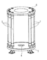
図1は本発明に係る自己洗浄槽保有型膜ろ過装置の全体構成の概念図、図2は膜モジュールの取付状態を示す斜視図、図3は自己洗浄槽保有型膜ろ過装置の平面図、図4は図3のa−a線矢視断面図、図5は図3のb−b線矢視断面図である。尚、図1は本発明に係る自己洗浄槽保有型膜ろ過装置の概念構成を示すものであり、該膜ろ過装置を構成する各構成部品や配管系統等の具体的な構成は図2〜図5に示されている。
膜ろ過装置1は、装置中央部に配置された返送・排水槽2、洗浄水槽3、及び逆洗計量槽4を有する。これら返送・排水槽2、洗浄水槽3、及び逆洗計量槽4は、下方から上方向に向けてこの順序で一体的に形成されている。尚、逆洗計量槽4の底部は、開口部4aを有しており、洗浄水槽3と逆洗計量槽4とは底部で連通している。従って、洗浄水槽3内に流入した膜ろ過水は逆洗計量槽4の底部から逆洗計量槽4内に流入するようになっている。
(Embodiment)
FIG. 1 is a conceptual diagram of the overall configuration of a self-cleaning tank-holding membrane filtration device according to the present invention, FIG. 2 is a perspective view showing a mounting state of a membrane module, and FIG. 3 is a plan view of the self-cleaning tank-holding membrane filtration device, 4 is a cross-sectional view taken along the line aa in FIG. 3, and FIG. 5 is a cross-sectional view taken along the line bb in FIG. In addition, FIG. 1 shows the conceptual structure of the self-cleaning tank holding type membrane filtration apparatus according to the present invention, and the specific structure of each component and piping system constituting the membrane filtration apparatus is shown in FIGS. 5.
The
膜ろ過装置1の下部には円盤状の原水供給ブロック5が配置され、膜ろ過装置1の上部には円盤状の膜ろ過水集水ブロック6が配置され、原水供給ブロック5の外方側端部と膜ろ過水集水ブロック6の外方側端部との間には複数個(本実施の形態では10個)の膜モジュール7が介在されている。これら膜モジュール7は、図2に示すように、膜ろ過装置1の中心部を中心とした円周上に立設されている。従って、各膜モジュール7と膜ろ過装置1の中心部との距離は、等しい。ここで、本発明で使用する膜モジュール7は、旭化成ケミカルズ(株)のケーシング収納型加圧型MF膜モジュールを選定しているが、メーカー、型式、膜種を限定するものではなく、加圧型MF膜モジュールであれば使用することができる互換性を有する構造としている。尚、図1においては図面の簡略化を図るため、1つの膜モジュール7のみが描かれている。
A disk-shaped raw water supply block 5 is disposed at the lower part of the
原水供給ブロック5は中央孔8を備えている。この中央孔8には、図4及び図5に示すように、排出管9及び排出管9の下端部付近を外装する外装管30が挿通している。排出管9の上端は返送・排水槽2の底部と連通している。また、外装管30は図4及び図5に示すように原水流入配管L10と接続されており、後述するように原水が外装管30を介して原水供給ブロック5の原水流入口5aから流入可能となっている。更に、外装管30は図3及び図4に示すように循環水配管L2と連通しており、後述するように循環水が外装管30を介して原水供給ブロック5の原水流入口5aから流入可能となっている。
原水供給ブロック5には、原水流入口5aと、原水流入口5aから放射線状に延び各膜モジュール7に至る原水供給流路11(図4及び図5参照)とが形成されている。原水流入口5aから原水供給ブロック5内に流入した原水は、各原水供給流路11を通って各膜モジュール7の下部に供給されるようになっている。
The raw water supply block 5 includes a
In the raw water supply block 5, a
膜ろ過水集水ブロック6は中央孔12を備えている。この中央孔12には逆洗計量槽4の上部が嵌り込み、逆洗計量槽4を収納する洗浄水槽3の上方開口を塞ぐようにして配置されている。膜ろ過水集水ブロック6は、各膜モジュール7の上部に連通し且つ洗浄水槽3に向けて延びる複数の膜ろ過水集水流路13(図4及び図5参照)が形成されている。このような構成により、各膜モジュール7でろ過された膜ろ過水は、各膜ろ過水集水流路13を通って洗浄水槽3に集水されることになる。
The membrane
また、各膜モジュール7と返送・排水槽2との間には連通管14が設けられている。この連通管14は、ろ過時には循環水を膜モジュール7から返送・排水槽2に導く働きをし、逆洗浄時には洗浄水槽3内の膜ろ過水を、膜ろ過水集水流路13から膜モジュール7を経て返送・排水槽2に導く働きをする。
A
また、返送・排水槽2の下方には空気槽15が設けられており、この空気槽15にはコンプレッサ16が接続されている。空気槽15は配管L1を介して逆洗計量槽4の上部に接続されている。
An
また、返送・排水槽2と原水供給ブロック5とは、排水管9、循環水配管L2及び外装管30を介して連通されている。この循環水配管L2には循環ポンプP1が設けられている。循環ポンプP1の駆動により、循環水は、返送・排水槽2→排水管9、循環水配管L2→外装管30→原水供給ブロック5→膜モジュール7→連通管14→返送・排水槽2の経路を経て循環されるようになっている。
また、膜モジュール7の上部には膜モジュール点検口20及び膜破断検出器21が備えられている。膜モジュール点検口20は膜モジュール7と同一径であり、従来例のような絞り込む形状のコネクタを用いていないので、膜モジュールの修繕の際に、装置から膜モジュールを取り外す必要がないという利点がある。尚、膜モジュールの修繕は、破断した膜チューブを専用の補修ピンで塞ぐことにより行われる。
また、膜ろ過水集水流路13には緊急遮断弁ASVが設けられている。後述するように、膜モジュール7の膜破断が膜破断検出器21によって検出されたときは、緊急遮断弁ASVは「閉」状態となり、膜モジュール点検口20から膜を修繕することができるようになっている。
Further, the return /
In addition, a membrane
The membrane
また、逆洗計量槽4の上部開口は天板22によって閉止されており、この天板22には、逆洗計量槽4内の液面レベルを計測する逆洗計量槽レベル計A1が設けられている。レベル計A1は、液面レベルがハイレベルからローレベルまでのレベルを計測可能となっている。また、天板22には膜ろ過水流出管41が接続されている。原水供給ブロック5内の各原水供給流路11には、膜モジュール供給元弁V20が設けられている。
Further, the upper opening of the
尚、図1において、V1は原水流入弁、V2はろ過水流出弁、V3は循環水弁、V4はエア供給弁、V5は洗浄排水弁、V6は返送・排水槽エア抜弁、V7はエアスクラビング弁である。膜ろ過装置1は、必要に応じて、膜ろ過水サンプル弁、モジュールサンプル弁、原水流量調節弁、逆洗流量調節弁等の各種の弁が設けられ、必要に応じて、原水流入圧力計、膜モジュール入口圧力計、膜モジュール出口圧力計、膜ろ過水濁度計等の各種の計測器が設けられている。
In FIG. 1, V1 is a raw water inflow valve, V2 is a filtered water outflow valve, V3 is a circulating water valve, V4 is an air supply valve, V5 is a washing drain valve, V6 is a return / drain tank air vent valve, and V7 is air scrubbing. It is a valve. The
上記構成の膜ろ過装置では、原水供給ブロック5に供給された原水は各膜モジュール7に対して均一に分配供給され、また、各膜モジュール7からの膜ろ過水は膜ろ過水集水ブロック6を通って中心部に配置された洗浄水槽3に均一に集水され、更に、循環水は各膜モジュール7から各連通管14を介して中心部に配置された返送・排水槽2に均一に集水されることになる。このことは、各膜モジュール7に対して均一な原水の供給、膜ろ過水および循環水の流出、逆洗水の供給を行うことができることを意味する。従って、従来の直管配置方式に比べると、膜モジュール間に生じていた不均一なファウリングを解消することができ、低動力で稼動することが可能となる。
尚、本発明に係る膜ろ過装置ではストレーナ40を設け、膜モジュールでろ過する前段処理としてストレーナ40によって原水を予めろ過しておくことが好ましい。
In the membrane filtration apparatus having the above configuration, the raw water supplied to the raw water supply block 5 is uniformly distributed and supplied to each
In addition, in the membrane filtration apparatus which concerns on this invention, it is preferable to provide the
次いで、上記構成の膜ろ過装置の運転動作について説明する。
A.ろ過工程
原水流入弁V1及びろ過水流出弁V2を「開」状態とする。これにより、原水は、原水供給ブロック5の原水供給流路11を経て膜モジュール7の下部に供給される。そして、原水は膜モジュール7を通過する際に膜ろ過処理される。膜ろ過水は、膜モジュール7の上部から膜ろ過水集水ブロック6の膜ろ過水集水流路13を通って洗浄水槽3に流入する。また、ろ過処理時においては、循環ポンプP1を「運転」状態とし、循環水弁V3を「開」状態とする。これにより、返送・排水槽2に貯留されている循環水が、原水供給ブロック5の原水供給流路11に流入し、膜モジュール7の膜表面を通り、連通管14から返送・排水槽2に戻る循環経路を巡る。そして、循環水が膜モジュール7の膜表面を通過することにより、クロスフローによるファウリング防止が行われる。このようなろ過工程が所定時間行われた後、物理洗浄工程に移る。
Next, the operation of the membrane filtration device having the above configuration will be described.
A. Filtration process The raw water inflow valve V1 and the filtrate water outflow valve V2 are set to the “open” state. Thereby, the raw water is supplied to the lower part of the
B.物理洗浄工程
物理洗浄工程はろ過継続時間30〜90分毎に1回当たり1〜2分間行われる。
原水流入弁V1、ろ過水流出弁V2及び循環水弁V3を「閉」状態とし、循環ポンプP1を「停止」する。また、エア供給弁V4及び洗浄排水弁V5を「開」状態とする。循環水弁V3を「閉」状態とし、循環ポンプP1を「停止」することにより、循環水の流れを停止する。また、エア供給弁V4を「開」状態とすることにより、逆洗計量槽4内のろ過水が洗浄水槽3上部から逆流して、膜ろ過水集水ブロック6の膜ろ過水集水流路13を通って膜モジュール7に供給され、膜モジュール7内が逆流洗浄されることになる。膜モジュール7からの流出水は、連通管14を通り返送・排水槽2に導かれ、洗浄排水弁V5を介して系外に排出される。この逆流洗浄処理と同時にエアスクラビング処理が実行される。即ち、エアスクラビング弁V7の「開」状態により、空気槽15内の圧縮空気が膜モジュール7の下部から流入し、膜モジュール7内の中空糸膜を振動させて膜面付着物を剥離・除去する。そして、所定時間経過後に、エアスクラビング弁V7を「閉」状態とし、エアスクラビング処理が終了する。このようにして、逆流洗浄処理及びエアスクラビング処理が終了した後は、フラッシング処理が実行される。
B. Physical cleaning process The physical cleaning process is performed for 1-2 minutes per filtration every 30-90 minutes of filtration duration.
The raw water inflow valve V1, the filtrate water outflow valve V2 and the circulating water valve V3 are set to the “closed” state, and the circulation pump P1 is “stopped”. Further, the air supply valve V4 and the cleaning drain valve V5 are set to the “open” state. The flow of the circulating water is stopped by setting the circulating water valve V3 to the “closed” state and “stopping” the circulation pump P1. Further, by setting the air supply valve V4 to the “open” state, the filtrate in the
フラッシング処理においては、原水流入弁V1を「開」状態とする。これにより、膜モジュール7に供給された原水はろ過膜を透過することなく膜表面をリンスし、返送・排水槽2に流入される。そして、フラッシング処理時間経過後は、洗浄排水弁V5を「閉」状態とする。
こうして、物理洗浄工程が行われた後は原則的にはろ過工程に戻り、ろ過工程と物理洗浄工程とが繰り返し行われる。但し、1日1回程度、物理洗浄の逆流洗浄及びエアスクラビング処理が終了した後に、膜破断検出工程が行われる。
In the flushing process, the raw water inlet valve V1 is set to the “open” state. As a result, the raw water supplied to the
Thus, after the physical cleaning process is performed, the process returns to the filtration process in principle, and the filtration process and the physical cleaning process are repeated. However, the membrane rupture detection step is performed about once a day after the backwashing of the physical cleaning and the air scrubbing process are completed.
C.膜破断検出工程
全ての膜モジュール7について膜破断検出工程が行われる。以下、具体的に説明する。
上記したように、各膜モジュール7の鉛直上には各々膜破断検出器21が設置されており、この膜破断検出器21によって膜モジュールに膜破断が生じていないかの検出が行われる。膜破断検出工程は物理洗浄の逆流洗浄及びエアスクラビング処理が終了した後に引き続き行われる。即ち、エア供給弁V4を「開」とし逆流洗浄を停止し、エアスクラビング弁V7も「閉」とする。次に、返送・排水槽エア抜弁V6を一旦「開」とし装置内が大気圧となったのを確認し、洗浄排水弁V5および返送・排水槽エア抜弁V6を「閉」とする。次に、膜破断検出器21に装備された電磁弁を「開」とし、エアスクラビング弁V7を徐々に「開」とする。この時、膜モジュール原水供給側の圧力は100KPaで調整する。エアーによる加圧を行うと膜モジュール7内の水が膜破断検出器21から流出するが、膜破断我が有る場合は連続気泡が発生し、膜破断検出器21のフロートセンサーを押し下げ、異常検出する。異常検出した膜モジュール7は緊急遮断弁ASVが「閉」とされ、次工程から使用が禁止される(尚、他の膜モジュール7で運転は継続される)。一定時間(約1分間)の膜破断検査を行った後「開」の状態である弁を全て「閉」とし、引き続きフラッシング工程に移行する。このようにして膜破断検出工程が行われるので、従来のように運転を停止して膜モジュールの取替えを行う必要がなく、膜ろ過装置の稼動率を向上することができる。
C. Membrane rupture detection step The membrane rupture detection step is performed for all the
As described above, the
(その他の事項)
上記実施の形態では、物理洗浄時の圧力供給はコンプレッサで行なっていたが、空気圧シリンダ、油圧シリンダ、加圧給水ポンプ等を用いてもよい。
(Other matters)
In the above embodiment, the pressure supply during the physical cleaning is performed by the compressor. However, a pneumatic cylinder, a hydraulic cylinder, a pressurized water supply pump, or the like may be used.
本発明は、装置内に物理洗浄に使用する洗浄水槽を一体に設け、効率良く膜ろ過処理を継続できる自己洗浄槽保有型膜ろ過装置に適用される。 The present invention is applied to a self-cleaning tank holding type membrane filtration apparatus in which a cleaning water tank used for physical cleaning is integrally provided in the apparatus and the membrane filtration treatment can be continued efficiently.
1:膜ろ過装置
2:返送・排水槽
3:洗浄水槽
4:逆洗計量槽
5:原水供給ブロック
6:膜ろ過水集水ブロック
7:膜モジュール
1: Membrane filtration device 2: Return / drainage tank 3: Wash water tank 4: Backwash metering tank 5: Raw water supply block 6: Membrane filtrate collection block 7: Membrane module
Claims (4)
装置下部には、原水が供給される原水供給ブロックが配置され、
装置上部には、膜モジュールによってろ過された膜ろ過水を集める膜ろ過水集水ブロックが配置され、
前記原水供給ブロックの外方側端部と前記膜ろ過水集水ブロック外方側端部との間には、複数個の膜モジュールが介在されており、これら膜モジュールは装置の中心部を中心とした円周上に立設されていることを特徴とする自己洗浄槽保有型膜ろ過装置。 In the central part of the device, a return / drainage tank, a washing water tank and a backwashing measuring tank are integrally formed,
A raw water supply block for supplying raw water is arranged at the lower part of the device,
At the top of the device, a membrane filtration water collection block that collects the membrane filtrate filtered by the membrane module is placed,
A plurality of membrane modules are interposed between the outer end of the raw water supply block and the outer end of the membrane filtrate collection block, and these membrane modules are centered on the center of the apparatus. A self-cleaning tank-equipped membrane filtration device characterized by being erected on the circumference.
前記膜ろ過水集水ブロックは、各膜モジュールの上部に連通すると共に洗浄水槽に向けて延び、各膜モジュールでろ過された膜ろ過水を洗浄水槽に集水する膜ろ過水集水流路を有し、
前記各膜モジュールと前記返送・排水槽との間には、ろ過時には循環水を膜モジュールから返送・排水槽に導き、逆洗浄時には洗浄水槽内の膜ろ過水を膜ろ過水集水流路から膜モジュールを経て返送・排水槽に導く連通管が設けられている請求項1記載の自己洗浄槽保有型膜ろ過装置。 The raw water supply block has a raw water supply flow path that extends radially from the central portion and supplies the raw water flowing into the central portion to the lower part of each membrane module,
The membrane filtration water collection block communicates with the upper part of each membrane module and extends toward the washing water tank, and has a membrane filtration water collection flow path for collecting the membrane filtration water filtered by each membrane module in the washing water tank. And
Between each membrane module and the return / drainage tank, circulating water is led from the membrane module to the return / drainage tank at the time of filtration, and the membrane filtrate in the washing water tank is passed through the membrane filtration water collecting flow path at the time of backwashing. The self-cleaning tank holding type membrane filtration apparatus according to claim 1, further comprising a communication pipe that leads to a return / drain tank through a module.
The self-cleaning tank possession type membrane filtration apparatus according to claim 1, wherein a membrane module inspection port for maintenance is provided on an extension of the membrane module attached to the membrane filtration water collecting block.
Priority Applications (1)
| Application Number | Priority Date | Filing Date | Title |
|---|---|---|---|
| JP2011272104A JP5761803B2 (en) | 2011-12-13 | 2011-12-13 | Self-cleaning tank type membrane filtration device |
Applications Claiming Priority (1)
| Application Number | Priority Date | Filing Date | Title |
|---|---|---|---|
| JP2011272104A JP5761803B2 (en) | 2011-12-13 | 2011-12-13 | Self-cleaning tank type membrane filtration device |
Related Child Applications (1)
| Application Number | Title | Priority Date | Filing Date |
|---|---|---|---|
| JP2015114585A Division JP5987087B2 (en) | 2015-06-05 | 2015-06-05 | Self-cleaning tank type membrane filtration device |
Publications (3)
| Publication Number | Publication Date |
|---|---|
| JP2013123652A JP2013123652A (en) | 2013-06-24 |
| JP2013123652A5 JP2013123652A5 (en) | 2014-02-06 |
| JP5761803B2 true JP5761803B2 (en) | 2015-08-12 |
Family
ID=48775237
Family Applications (1)
| Application Number | Title | Priority Date | Filing Date |
|---|---|---|---|
| JP2011272104A Active JP5761803B2 (en) | 2011-12-13 | 2011-12-13 | Self-cleaning tank type membrane filtration device |
Country Status (1)
| Country | Link |
|---|---|
| JP (1) | JP5761803B2 (en) |
Families Citing this family (2)
| Publication number | Priority date | Publication date | Assignee | Title |
|---|---|---|---|---|
| JP5695727B2 (en) * | 2013-08-21 | 2015-04-08 | アタカ大機株式会社 | Self-cleaning tank type membrane filtration device |
| JP5855778B2 (en) * | 2013-08-21 | 2016-02-09 | 日立造船株式会社 | Self-cleaning tank type membrane filtration device |
Family Cites Families (5)
| Publication number | Priority date | Publication date | Assignee | Title |
|---|---|---|---|---|
| JP3602349B2 (en) * | 1998-10-22 | 2004-12-15 | 株式会社神鋼環境ソリューション | Hollow fiber membrane separation device and movable hollow fiber membrane separation device |
| JP3123456U (en) * | 2006-01-17 | 2006-07-20 | 久雄 泉 | Reverse cleaning filtration device |
| JP3123473U (en) * | 2006-02-20 | 2006-07-20 | 久雄 泉 | Filter housing filtration device |
| JP5175695B2 (en) * | 2008-11-25 | 2013-04-03 | アタカ大機株式会社 | Membrane separator |
| JP5244672B2 (en) * | 2009-03-27 | 2013-07-24 | メタウォーター株式会社 | Water treatment system and water treatment method |
-
2011
- 2011-12-13 JP JP2011272104A patent/JP5761803B2/en active Active
Also Published As
| Publication number | Publication date |
|---|---|
| JP2013123652A (en) | 2013-06-24 |
Similar Documents
| Publication | Publication Date | Title |
|---|---|---|
| KR100679231B1 (en) | Flexible-fiber filter module | |
| EP1463578A1 (en) | Methods for improving filtration performance of hollow fiber membranes | |
| JPS62262710A (en) | Hollow yarn membrane filter | |
| JP5695727B2 (en) | Self-cleaning tank type membrane filtration device | |
| JP5761803B2 (en) | Self-cleaning tank type membrane filtration device | |
| JP5855778B2 (en) | Self-cleaning tank type membrane filtration device | |
| JP5987087B2 (en) | Self-cleaning tank type membrane filtration device | |
| JP2002058969A (en) | Method of maintainance of managing immersion type membrane separator | |
| JP2003093808A (en) | Low pressure, self-washing type filtration apparatus | |
| JP6457904B2 (en) | Self-cleaning tank type membrane filtration device | |
| CN104805652B (en) | Washer | |
| JP5230073B2 (en) | Membrane damage detection test method for filtration membranes | |
| CN107626132B (en) | High-performance backwashing device of bundle tube type filter | |
| KR101100715B1 (en) | A water-treatment apparatus using membrane module, and method thereby | |
| KR100745121B1 (en) | Filtering apparatus | |
| CN104436774A (en) | Mechanical filter | |
| CN114364444B (en) | Water purifier and filter for water purifier | |
| JP2004216264A (en) | Hollow fiber membrane filteration apparatus provided with air tank for back washing | |
| JP7257824B2 (en) | Particle removal membrane device, ultrapure water production device, and ultrapure water production method | |
| JP5251522B2 (en) | Membrane separator | |
| KR102438222B1 (en) | Multichannel sampling filtering device | |
| JP2013123652A5 (en) | ||
| CN214319777U (en) | A wiper mechanism for RO membrane | |
| KR200420293Y1 (en) | Automatic Filter Cleaning and Fluid Temperature Maintenance Using Backflow | |
| CN211724872U (en) | Back-flushing anti-blocking device of precision filter |
Legal Events
| Date | Code | Title | Description |
|---|---|---|---|
| A521 | Request for written amendment filed |
Free format text: JAPANESE INTERMEDIATE CODE: A523 Effective date: 20131216 |
|
| A621 | Written request for application examination |
Free format text: JAPANESE INTERMEDIATE CODE: A621 Effective date: 20131216 |
|
| A977 | Report on retrieval |
Free format text: JAPANESE INTERMEDIATE CODE: A971007 Effective date: 20140821 |
|
| A131 | Notification of reasons for refusal |
Free format text: JAPANESE INTERMEDIATE CODE: A131 Effective date: 20140827 |
|
| TRDD | Decision of grant or rejection written | ||
| A01 | Written decision to grant a patent or to grant a registration (utility model) |
Free format text: JAPANESE INTERMEDIATE CODE: A01 Effective date: 20150507 |
|
| A711 | Notification of change in applicant |
Free format text: JAPANESE INTERMEDIATE CODE: A712 Effective date: 20150605 |
|
| A61 | First payment of annual fees (during grant procedure) |
Free format text: JAPANESE INTERMEDIATE CODE: A61 Effective date: 20150605 |
|
| R150 | Certificate of patent or registration of utility model |
Ref document number: 5761803 Country of ref document: JP Free format text: JAPANESE INTERMEDIATE CODE: R150 |
|
| R250 | Receipt of annual fees |
Free format text: JAPANESE INTERMEDIATE CODE: R250 |