JP5757397B2 - Exposure method, exposure apparatus, and device manufacturing method - Google Patents
Exposure method, exposure apparatus, and device manufacturing method Download PDFInfo
- Publication number
- JP5757397B2 JP5757397B2 JP2011048494A JP2011048494A JP5757397B2 JP 5757397 B2 JP5757397 B2 JP 5757397B2 JP 2011048494 A JP2011048494 A JP 2011048494A JP 2011048494 A JP2011048494 A JP 2011048494A JP 5757397 B2 JP5757397 B2 JP 5757397B2
- Authority
- JP
- Japan
- Prior art keywords
- moving body
- measurement
- measurement system
- measuring
- positioning
- Prior art date
- Legal status (The legal status is an assumption and is not a legal conclusion. Google has not performed a legal analysis and makes no representation as to the accuracy of the status listed.)
- Active
Links
Images


Landscapes
- Container, Conveyance, Adherence, Positioning, Of Wafer (AREA)
- Exposure Of Semiconductors, Excluding Electron Or Ion Beam Exposure (AREA)
- Exposure And Positioning Against Photoresist Photosensitive Materials (AREA)
Description
本発明は、露光方法及び露光装置、並びにデバイス製造方法に係り、さらに詳しくは、半導体素子等のマイクロデバイスを製造するリソグラフィ工程で用いられる露光方法及び露光装置、並びに前記露光方法を利用するデバイス製造方法に関する。 The present invention relates to an exposure method, an exposure apparatus, and a device manufacturing method, and more particularly, an exposure method and an exposure apparatus used in a lithography process for manufacturing a microdevice such as a semiconductor element, and a device manufacturing using the exposure method. Regarding the method.
半導体素子(集積回路等)、液晶表示素子等の電子デバイス(マイクロデバイス)を製造するリソグラフィ工程では、主として、ステップ・アンド・リピート方式の露光装置(いわゆるステッパ)、ステップ・アンド・スキャン方式の露光装置(いわゆるスキャニング・ステッパ(スキャナとも呼ばれる))等が用いられている。 In lithography processes for manufacturing electronic devices (microdevices) such as semiconductor elements (integrated circuits, etc.) and liquid crystal display elements, step-and-repeat exposure apparatuses (so-called steppers) and step-and-scan exposures are mainly used. An apparatus (a so-called scanning stepper (also called a scanner)) or the like is used.
この種の露光装置では、半導体素子の高集積化によるデバイスパターンの微細化に伴い、高い重ね合わせ精度(位置合わせ精度)が要求されるようになってきた。そのため、パターンが形成されるウエハ等(基板)の位置計測に一層高い精度が要求されるようになってきた。 In this type of exposure apparatus, a high overlay accuracy (positioning accuracy) has been required with the miniaturization of device patterns due to high integration of semiconductor elements. Therefore, higher accuracy has been required for position measurement of a wafer or the like (substrate) on which a pattern is formed.
かかる要求に応える装置として、例えば特許文献1には、基板テーブル上に搭載された複数のエンコーダタイプのセンサ(エンコーダヘッド)を用いる位置計測システムを備えた露光装置が提案されている。この露光装置では、エンコーダヘッドは、基板テーブルに対向して配置されたスケールに計測ビームを照射し、スケールからの戻りビームを受光することによって、基板テーブルの位置を計測する。スケールは、複数のエンコーダヘッドのそれぞれが対向する複数の部分から構成され、投影光学系直下の領域を除く基板テーブルの移動領域をカバーしている。
As an apparatus that meets such demands, for example,
また、露光装置では、高いスループットも求められる。かかる要請に応え得るものとして、基板ステージが複数、例えば2つ設けられたツインステージタイプの露光装置が知られている。この種の露光装置では、2つの基板ステージで、異なる動作、例えば露光動作とアライメント動作を並行して行うことで、スループットの向上が図られている。ツインステージタイプの露光装置では、それぞれの基板ステージの動きの自由度を最大限に確保するため、その駆動源として平面モータが採用される(例えば、特許文献2参照)。 The exposure apparatus is also required to have high throughput. A twin stage type exposure apparatus provided with a plurality of, for example, two substrate stages is known as a device that can meet such a demand. In this type of exposure apparatus, throughput is improved by performing different operations, for example, an exposure operation and an alignment operation in parallel on two substrate stages. In a twin stage type exposure apparatus, a planar motor is employed as a drive source in order to ensure the maximum degree of freedom of movement of each substrate stage (see, for example, Patent Document 2).
しかるに、最近になって、ツインステージタイプの露光装置では、一方の基板ステージの移動に伴って、他方の基板ステージの位置計測を行う位置計測系(エンコーダなど)の計測値が微小ではあるが影響を受けることが判明した。今後のデバイスルールが32nmよりさらに微細となる時代においては、かかる位置計測誤差も無視することができなくなる。 However, recently, in a twin stage type exposure apparatus, the measurement value of a position measurement system (such as an encoder) that measures the position of the other substrate stage is very small as the one substrate stage moves. Turned out to receive. In the era when device rules in the future become finer than 32 nm, such position measurement errors cannot be ignored.
発明者は、上記の位置計測誤差の主要因をつきとめるべく、鋭意研究を行った結果、基板ステージの位置の変化に起因する装置内の磁場変動(変化)が主要因であることが判明した。また、発明者は、さらにシミュレーション等を行った結果、2つの基板ステージの存在そのものが、お互いに影響を与えること、すなわち他方の基板ステージの位置が変化しない場合であっても、一方の基板ステージの位置が変化した場合に、その一方の基板ステージの位置を計測する位置計測系の計測値に、計測誤差が生じることが判明した。この場合、一方の基板ステージの位置が変化することによって、同一位置にとどまっている他方の基板ステージとの位置関係が変化するので、2つのステージ間での磁場が変動(変化)するため、上記の計測誤差が生じると考えられる。本発明は、かかる事情の下でなされたものである。 The inventor conducted intensive research to find out the main cause of the above-described position measurement error, and as a result, it was found that the magnetic field fluctuation (change) in the apparatus due to the change in the position of the substrate stage was the main factor. Further, as a result of further simulation and the like, the inventor also has an influence on one substrate stage even if the existence of the two substrate stages influences each other, that is, the position of the other substrate stage does not change. It has been found that a measurement error occurs in the measurement value of the position measurement system that measures the position of one of the substrate stages when the position of is changed. In this case, when the position of one substrate stage changes, the positional relationship with the other substrate stage that remains at the same position changes, so the magnetic field between the two stages fluctuates (changes). It is considered that a measurement error of The present invention has been made under such circumstances.
本発明の第1の態様によれば、エネルギビームで物体を露光して前記物体上にパターンを形成する露光方法であって、所定平面に平行なガイド面を有する定盤上で平面モータによって個別に駆動される第1、第2移動体のそれぞれに対する位置計測系による第1及び第2位置情報と、前記第1及び第2移動体の位置に応じた第1補正情報とに基づいて、前記物体を保持する前記第1移動体を駆動することを含む露光方法が、提供される。 According to the first aspect of the present invention, there is provided an exposure method in which an object is exposed with an energy beam to form a pattern on the object, and individually by a planar motor on a surface plate having a guide surface parallel to a predetermined plane. Based on the first and second position information by the position measurement system for each of the first and second moving bodies driven by the first and second correction information according to the positions of the first and second moving bodies, An exposure method including driving the first moving body that holds an object is provided.
これによれば、位置計測系によって計測される第1移動体の第1位置情報に含まれる第1及び第2移動体の位置に応じた計測誤差を補正することができ、結果的に第1移動体を高精度に駆動することが可能となる。 According to this, the measurement error according to the position of the 1st and 2nd moving body contained in the 1st position information of the 1st moving body measured by a position measuring system can be amended, and as a result, the 1st The moving body can be driven with high accuracy.
本発明の第2の態様によれば、本発明の露光方法を用いて、物体上にパターンを形成することと、前記パターンが形成された前記物体を現像することと、を含むデバイス製造方法が、提供される。 According to a second aspect of the present invention, there is provided a device manufacturing method comprising: forming a pattern on an object using the exposure method of the present invention; and developing the object on which the pattern is formed. Provided.
本発明の第3の態様によれば、エネルギビームで物体を露光して前記物体上にパターンを形成する露光装置であって、所定平面に平行なガイド面を有する定盤と、前記定盤内に設けられた固定子と、前記ガイド面を介して前記固定子に対向する第1及び第2可動子とを含んで構成される平面モータと、前記第1及び第2可動子をそれぞれ有し、前記平面モータにより前記ガイド面に沿って駆動される第1及び第2移動体と、前記第1及び第2移動体のそれぞれの位置を計測する位置計測系と、前記位置計測系からの前記第1移動体の位置情報と、前記位置計測系からの前記第2移動体の位置情報と、前記第1及び第2移動体の位置に応じた第1補正情報とに基づいて、前記物体を保持する前記第1移動体を駆動する駆動装置と、を備える露光装置が、提供される。 According to a third aspect of the present invention, there is provided an exposure apparatus that exposes an object with an energy beam to form a pattern on the object, the surface plate having a guide surface parallel to a predetermined plane; A planar motor configured to include a stator provided on the first and second movable elements facing the stator via the guide surface, and the first and second movable elements, respectively. The first and second moving bodies driven along the guide surface by the planar motor, the position measuring system for measuring the positions of the first and second moving bodies, and the position measuring system from the position measuring system. Based on the position information of the first moving body, the position information of the second moving body from the position measurement system, and the first correction information corresponding to the positions of the first and second moving bodies, the object is And a driving device that drives the first moving body to be held. Location is provided.
これによれば、位置計測系によって計測される第1移動体の第1位置情報に含まれる第1及び第2移動体の位置に応じた計測誤差を補正することができ、結果的に第1移動体を高精度に駆動することが可能となる。 According to this, the measurement error according to the position of the 1st and 2nd moving body contained in the 1st position information of the 1st moving body measured by a position measuring system can be amended, and as a result, the 1st The moving body can be driven with high accuracy.
以下、本発明の一実施形態について、図1〜図9に基づいて説明する。 DESCRIPTION OF EXEMPLARY EMBODIMENTS Hereinafter, an embodiment of the invention will be described with reference to FIGS.
図1には、一実施形態に係る露光装置100の概略構成が示されている。露光装置100は、ステップ・アンド・スキャン方式の投影露光装置、すなわち、いわゆるスキャナである。後述するように、本実施形態では投影光学系PLが設けられており、以下においては、投影光学系PLの光軸AXと平行な方向をZ軸方向、これに直交する面内でレチクルとウエハとが相対走査される方向をY軸方向、Z軸及びY軸に直交する方向をX軸方向とし、X軸、Y軸、及びZ軸回りの回転(傾斜)方向をそれぞれθx、θy、及びθz方向として説明を行なう。
FIG. 1 shows a schematic configuration of an
露光装置100は、照明系10、レチクルRを保持するレチクルステージRST、投影ユニットPU、ウエハWが載置されるウエハステージWST1,WST2を含むウエハステージ装置50、及びこれらの制御系等を備えている。
The
照明系10は、例えば米国特許出願公開第2003/0025890号明細書などに開示されるように、光源と、オプティカルインテグレータ等を含む照度均一化光学系、及びレチクルブラインド等(いずれも不図示)を有する照明光学系とを含む。照明系10は、レチクルブラインド(マスキングシステム)で規定されたレチクルR上のスリット状の照明領域IARを照明光(露光光)ILによりほぼ均一な照度で照明する。ここで、照明光ILとしては、一例としてArFエキシマレーザ光(波長193nm)が用いられている。
The
レチクルステージRST上には、回路パターンなどがそのパターン面(図1における下面)に形成されたレチクルRが、例えば真空吸着により固定されている。レチクルステージRSTは、例えばリニアモータ等を含むレチクルステージ駆動系11(図1では不図示、図6参照)によって、XY平面内で微少駆動可能であるとともに、走査方向(図1における紙面直交方向であるY軸方向)に所定の走査速度で駆動可能となっている。 On reticle stage RST, reticle R on which a circuit pattern or the like is formed on its pattern surface (the lower surface in FIG. 1) is fixed, for example, by vacuum suction. The reticle stage RST can be finely driven in the XY plane by a reticle stage drive system 11 (not shown in FIG. 1, refer to FIG. 6) including a linear motor, for example, and in the scanning direction (in the direction orthogonal to the paper surface in FIG. 1). It can be driven at a predetermined scanning speed in a certain Y-axis direction.
レチクルステージRSTのXY平面(移動面)内の位置情報(θz方向の位置(θz回転量)の情報を含む)は、図1に示される、移動鏡15(実際には、Y軸方向に直交する反射面を有するY移動鏡(あるいは、レトロリフレクタ)とX軸方向に直交する反射面を有するX移動鏡とが設けられている)に測長ビームを照射するレチクルレーザ干渉計(以下、「レチクル干渉計」という)16によって例えば0.25nm程度の分解能で常時検出される。なお、レチクルRの少なくとも3自由度方向の位置情報を計測するために、レチクル干渉計16の代わりに、あるいはそれと組み合わせて、例えば米国特許出願公開第2007/0288121号明細書などに開示されているエンコーダシステムを用いても良い。
Position information (including information on the position in the θz direction (θz rotation amount)) in the XY plane (moving plane) of reticle stage RST is shown in FIG. 1 as moving mirror 15 (actually perpendicular to the Y-axis direction). A reticle laser interferometer (hereinafter referred to as “a movable mirror having a reflecting surface that is provided with an X moving mirror having a reflecting surface orthogonal to the X-axis direction”). For example, it is always detected with a resolution of about 0.25 nm. In order to measure the position information of the reticle R in the direction of at least three degrees of freedom, it is disclosed in, for example, US Patent Application Publication No. 2007/0288121 instead of or in combination with the
投影ユニットPUは、レチクルステージRSTの図1における下方(−Z側)に配置され、不図示のボディの一部を構成するメインフレーム(メトロロジーフレーム)に保持されている。投影ユニットPUは、鏡筒40と、該鏡筒40に保持された複数の光学素子から成る投影光学系PLとを有している。投影光学系PLとしては、例えば、Z軸方向と平行な光軸AXに沿って配列された複数の光学素子(レンズエレメント)からなる屈折光学系が用いられている。投影光学系PLは、例えば両側テレセントリックで、所定の投影倍率(例えば1/4倍、1/5倍又は1/8倍など)を有する。このため、照明系10からの照明光ILによって照明領域IARが照明されると、投影光学系PLの第1面(物体面)とパターン面がほぼ一致して配置されるレチクルRを通過した照明光ILにより、投影光学系PLを介してその照明領域IAR内のレチクルRの回路パターンの縮小像(回路パターンの一部の縮小像)が、投影光学系PLの第2面(像面)側に配置される、表面にレジスト(感応剤)が塗布されたウエハW上の前記照明領域IARに共役な領域(露光領域)IAに形成される。そして、レチクルステージRSTとウエハステージWST1、WST2との同期駆動によって、照明領域IAR(照明光IL)に対してレチクルRを走査方向(Y軸方向)に相対移動させるとともに、露光領域IA(照明光IL)に対してウエハWを走査方向(Y軸方向)に相対移動させることで、ウエハW上の1つのショット領域(区画領域)の走査露光が行われ、そのショット領域にレチクルRのパターンが転写される。すなわち、本実施形態では照明系10、及び投影光学系PLによってウエハW上にレチクルRのパターンが生成され、照明光ILによるウエハW上の感応層(レジスト層)の露光によってウエハW上にそのパターンが形成される。
Projection unit PU is arranged below reticle stage RST in FIG. 1 (on the −Z side), and is held by a main frame (metrology frame) that forms part of a body (not shown). The projection unit PU has a
なお、メインフレームは、従来用いられている門型、及び例えば米国特許出願公開第2008/0068568号明細書などに開示される吊り下げ支持型のいずれであっても良い。 The main frame may be any of a conventionally used portal type and a suspension support type disclosed in, for example, US Patent Application Publication No. 2008/0068568.
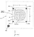
鏡筒40の−Z側端部の周囲には、例えば鏡筒40の下端面とほぼ同一面となる高さで、スケール板21がXY平面に平行に配置されている。スケール板21の中央には、図2に示されるように、矩形又は正方形の開口21aが形成され、開口21aの内部に鏡筒40の−Z側端部が配置されている。スケール板21のX軸方向及びY軸方向の幅はそれぞれA及びBである。この場合、AとBとは、同一であっても良い、すなわち。スケール板21は、正方形であっても良い。また、開口21aは、その内部に投影ユニットPUの鏡筒40の下端が配置できれば、矩形又は正方形に限らず、円形であっても良い。
Around the −Z side end of the
スケール板21は、投影ユニットPU及びアライメント系ALG等を支持するメインフレーム(メトロロジーフレーム)の下面(−Z側の面)に固定(又は吊り下げ支持)されている。
The
スケール板21から+X方向に所定距離離間した位置には、図1に示されるように、スケール板22が、メインフレーム(メトロロジーフレーム)の下面(−Z側の面)に固定(又は吊り下げ支持)されている。スケール板22は、図3に示されるように、スケール板21と同様に構成されており、その開口22aの内部の中央には、アライメント系ALGの−Z側端部が挿入されている(図1参照)。ここで、スケール板22は、必ずしもスケール板21と同様に構成する必要はなく、例えば開口22aは、開口21aと形状及び/又は大きさが異なっていても良い。要は、開口22aは、その内部にアライメント系ALGの−Z側端部が挿入可能であれば良い。なお、図1等ではスケール板21,22が固定されたメインフレーム(メトロロジーフレーム)23の一部が示されている。
As shown in FIG. 1, the
スケール板21,22の下面(−Z側の面)には、X軸を基準とする45度方向(Y軸を基準とする−45度方向)を周期方向とする所定ピッチ、例えば1μmの格子と、X軸を基準とする−45度方向(Y軸を基準とする−135度方向)を周期方向とする所定ピッチ、例えば1μmの格子とから成る反射型の2次元グレーティングRG(図2、図3及び図4参照)が形成されている。スケール板21,22の2次元グレーティングRGは、それぞれ、露光動作時及びアライメント(計測)時におけるウエハステージWST1,WST2の移動範囲をカバーしている。ここで、2次元グレーティングRGは、必ずしも上記の二方向を周期方向とする必要はなく、XY平面内の二軸方向であれば良い。従って、周期方向は、例えばX軸方向、Y軸方向であっても良い。
On the lower surfaces (surfaces on the −Z side) of the
ウエハステージ装置50は、床面上に複数(例えば3つ又は4つ)の防振機構(図示省略)によってほぼ水平に支持されたステージベース12、該ステージベース12上に配置されたウエハステージWST1,WST2、該ウエハステージWST1,WST2を駆動するウエハステージ駆動系27(図1では一部のみ図示、図6参照)、及びウエハステージWST1,WST2の位置を計測する計測系等を備えている。計測系は、図6に示される、エンコーダシステム70,71及びウエハレーザ干渉計システム(以下、ウエハ干渉計システムと略記する)18等を備えている。なお、エンコーダシステム70,71及びウエハ干渉計システム18については、さらに後述する。
ステージベース12は、平板状の外形を有する部材からなり、その上面は平坦度が非常に高く仕上げられ、ウエハステージWST1,WST2の移動の際のガイド面とされている。ステージベース12の内部には、XY平面内でXY二次元配列された複数の磁石から成る磁石ユニット14aが収容されている。
The
ウエハステージWST1は、図1に示されるように、ステージ本体91と、該ステージ本体91の上方に配置され、Z・チルト駆動機構28(図1では不図示、図6参照)によって、ステージ本体91に対して非接触で支持されたウエハテーブルWTB1とを有している。Z・チルト駆動機構28は、例えばウエハテーブルWTB1をそれぞれ支持するとともに、各支持点で独立してZ軸方向に駆動する3つのボイスコイルモータなどで構成することができる。この場合、ウエハテーブルWTB1は、Z・チルト駆動機構28によって、電磁力等の上向きの力(斥力)と、自重を含む下向きの力(引力)との釣り合いを3点で調整することで、非接触で支持されるとともに、Z軸方向、θx方向、及びθy方向の3自由度方向に微小駆動される。ステージ本体91の底部には、スライダ部91aが設けられている。スライダ部91aは、XY二次元方向を行方向、列方向としてマトリックス状に配置された複数のコイルを含むコイルユニット(不図示)と、該コイルユニットを収容する筐体と、該筐体の底面の周囲に設けられた複数のエアベアリングとを有している。コイルユニットは、前述の磁石ユニット14aとともに、例えば米国特許第6,437,463号明細書及び米国特許第4,654,571号明細書などに開示されるローレンツ電磁力駆動による平面モータ30を構成している。
As shown in FIG. 1, wafer stage WST1 is arranged above stage
ウエハステージWST1は、上記複数のエアベアリングによってステージベース12上に所定のクリアランス、例えば数μm程度のクリアランスを介して浮上支持され、平面モータ30によって、X軸方向、Y軸方向及びθz方向に駆動される。従って、ウエハテーブルWTB1(ウエハW)は、ステージベース12に対して、6自由度方向(X軸方向、Y軸方向、Z軸方向、θx方向、θy方向及びθz方向(以下、X,Y,Z,θx、θy、θz)と略記する)に駆動可能である。
Wafer stage WST1 is levitated and supported on
本実施形態では、コイルユニットを構成する各コイル(不図示)に供給される電流の大きさ及び方向が、主制御装置20によって制御される。図6に示されるように、平面モータ30と、前述のZ・チルト駆動機構28とを含んで、ウエハステージ駆動系27が構成されている。また、例えば米国特許第6,437,463号明細書に開示されるXY方向のみでなく、Z方向の力をも発生させる平面モータ(磁気浮上型の平面モータ)を用いることで、ウエハステージWST1を6自由度方向に駆動することとしても良い。また、ウエハテーブルWTB1を、X軸方向、Y軸方向、θz方向のうちの少なくとも一方向に微動可能としても良い。
In the present embodiment, the
ウエハテーブルWTB1上には、不図示のウエハホルダを介してウエハWが載置され、不図示のチャック機構によって例えば真空吸着(又は静電吸着)され、固定されている。また、ウエハテーブルWTB1上の1つの角部近傍には、アライメント系ALGにより検出される第2基準マークと、該第2基準マークを挟んでX軸方向の両側に配置された一対の第1基準マークとがその表面に形成された基準マーク板FMが、固定されている。一対の第1基準マークは、後述する一対のレチクルアライメント系により検出される。基準マーク板FMはその表面がウエハWとほぼ同一面となるように設定されている。 On wafer table WTB1, wafer W is placed via a wafer holder (not shown), and, for example, vacuum chucked (or electrostatic chucked) is fixed by a chuck mechanism (not shown). Further, in the vicinity of one corner on wafer table WTB1, there are a second reference mark detected by alignment system ALG and a pair of first reference marks arranged on both sides in the X-axis direction across the second reference mark. A reference mark plate FM on which a mark is formed is fixed. The pair of first reference marks is detected by a pair of reticle alignment systems described later. The reference mark plate FM is set so that its surface is substantially flush with the wafer W.
ウエハステージWST2も、ウエハステージWST1と同様に構成されている。 Wafer stage WST2 is configured similarly to wafer stage WST1.
エンコーダシステム70,71は、それぞれ、投影光学系PL直下の領域を含む露光時移動領域とアライメント系ALG直下の領域を含むアライメント時移動領域におけるウエハステージWST1,WST2の6自由度方向(X,Y,Z,θx,θy,θz)の位置情報を求める(計測する)。ここで、エンコーダシステム70,71の構成等について詳述する。
ウエハテーブルWTB1,WTB2には、それぞれ図2及び図3の平面図に示されるように、その4隅のそれぞれにエンコーダヘッド(以下、適宜、ヘッドと略称する)601〜604が配置されている。ここで、ヘッド601,602間のX軸方向の離間距離とヘッド603,604間のX軸方向の離間距離は互いに等しくAである。また、ヘッド601,604間のY軸方向の離間距離とヘッド602,603間のY軸方向の離間距離は互いに等しくBである。これらヘッドの離間距離A,Bは、スケール板21の開口21aのX軸、Y軸方向の幅よりも大きい。ヘッド601〜604は、図4にヘッド601を代表的に採り上げて示されるように、ウエハテーブルWTB1,WTB2に形成されたZ軸方向の所定深さの穴の内部にそれぞれ収容されている。
The wafer table WTBl, WTB2, as shown in a plan view, respectively, of FIG. 2 and FIG. 3, the four corners of the encoder heads each (hereinafter appropriately abbreviated as the head) 60 1 to 60 4 is arranged Yes. The
ヘッド601は、図5に示されるように、X軸を基準とする135度方向(すなわちX軸を基準とする−45度方向)及びZ軸方向を計測方向とする2次元ヘッドである。同様に、ヘッド602〜604は、それぞれ、X軸を基準とする225度方向(すなわちX軸を基準とする45度方向)及びZ軸方向、X軸を基準とする315度方向(すなわちX軸を基準とする−45度方向)及びZ軸方向、X軸を基準とする45度方向及びZ軸方向を計測方向とする2次元ヘッドである。ヘッド601〜604としては、例えば米国特許第7,561,280号明細書に開示される変位計測センサヘッドを用いることができる。ヘッド601〜604は、スケール板21,22の表面に形成された2次元グレーティングRGに計測ビームを照射し、2次元グレーティングRGからの反射・回折ビームを受光することにより、それぞれの計測方向についてのウエハテーブルWTB1,WTB2(ウエハステージWST1,WST2)の位置を計測する。
Head 60 1, as shown in FIG. 5, is a two-dimensional head to the (-45 ° direction with respect to the other words the X-axis) and Z-axis direction 135 degree direction relative to the X-axis measurement direction. Similarly, the heads 60 2 to 60 4 respectively have a 225 degree direction with respect to the X axis (that is, a 45 degree direction with respect to the X axis), a Z axis direction, and a 315 degree direction with respect to the X axis (that is, This is a two-dimensional head in which the measurement direction is the −45 degree direction with respect to the X axis) and the Z axis direction, the 45 degree direction with respect to the X axis and the Z axis direction. As the heads 60 1 to 60 4 , for example, a displacement measurement sensor head disclosed in US Pat. No. 7,561,280 can be used. The heads 60 1 to 60 4 irradiate the two-dimensional grating RG formed on the surfaces of the
上述のようにして構成されたヘッド601〜604では、計測ビームの空気中での光路長が極短いため、空気揺らぎの影響が殆ど無視できる。ただし、本実施形態では、光源及び光検出器は各ヘッドの外部、具体的には、ステージ本体91の内部(又は外部)に設けられ、光学系のみが各ヘッドの内部に設けられている。そして、光源及び光検出器と、光学系とは、不図示の光ファイバを介して光学的に接続されている。なお、ウエハテーブルWTB1(微動ステージ)の位置決め精度を向上させるため、ステージ本体91(粗動ステージ)とウエハテーブルWTB1(微動ステージ)との間(以下、粗微動ステージ間と略述する)で、レーザ光等を空中伝送しても良いし、あるいはヘッドをステージ本体91(粗動ステージ)に設けて、該ヘッドによりステージ本体91(粗動ステージ)の位置を計測し、かつ別のセンサで粗微動ステージ間の相対変位を計測する構成としても良い。
In the head 60 through 603 4 configured as described above, since the optical path length in air of the measuring beam is extremely short, the influence of air fluctuation can mostly be ignored. However, in this embodiment, the light source and the photodetector are provided outside each head, specifically, inside (or outside) the stage
ウエハステージWST1,WST2が投影光学系PL直下の領域を含む露光時移動領域内に位置する際には、ヘッド601は、スケール板21に計測ビーム(計測光)を照射し、スケール板21の表面(下面)に形成されたX軸を基準とする135度方向を周期方向とする格子からの回折ビームを受光して、ウエハステージWST1,WST2の135度方向及びZ軸方向の位置を計測する2次元エンコーダ701(図6参照)を構成する。同様に、ヘッド602〜604は、それぞれ、スケール板21に計測ビーム(計測光)を照射し、スケール板21の表面(下面)に形成されたX軸を基準とする225度方向、315度方向、及び45度方向を周期方向とする格子からの回折ビームを受光して、ウエハステージWSTの225度方向及びZ軸方向の位置、315度方向及びZ軸方向の位置、及び45度方向及びZ軸方向の位置、を計測する2次元エンコーダ702〜704(図6参照)をそれぞれ構成する。
When wafer stages WST1, WST2 is positioned on the exposure time movement area including a region directly below the projection optical system PL, the head 60 1, the
また、ウエハステージWST1,WST2がアライメント系ALG直下の領域を含むアライメント時移動領域内に位置する際には、ヘッド601は、スケール板22に計測ビーム(計測光)を照射し、スケール板22の表面(下面)に形成されたX軸を基準とする135度方向を周期方向とする格子からの回折ビームを受光して、ウエハステージWST1,WST2の135度方向及びZ軸方向の位置を計測する2次元エンコーダ711(図6参照)を構成する。同様に、ヘッド602〜604は、それぞれ、スケール板22に計測ビーム(計測光)を照射し、スケール板22の表面(下面)に形成されたX軸を基準とする225度方向、315度方向、及び45度方向を周期方向とする格子からの回折ビームを受光して、ウエハステージWST1,WST2の225度方向及びZ軸方向の位置、315度方向及びZ軸方向の位置、及び45度方向及びZ軸方向の位置、を計測する2次元エンコーダ712〜714(図6参照)をそれぞれ構成する。
Further, when the wafer stages WST1, WST2 is positioned in alignment during movement area including a region immediately below the alignment system ALG, the head 60 1 irradiates a measurement beam (measurement light)
2次元エンコーダ(以下、適宜、エンコーダと略称する)701〜704,711〜714のそれぞれの計測値は、主制御装置20(図6参照)に供給される。主制御装置20は、2次元グレーティングRGが形成されたスケール板21の下面に対向する少なくとも3つのエンコーダ(すなわち、有効な計測値を出力している少なくとも3つのエンコーダ)の計測値に基づいて、投影光学系PL直下の領域を含む露光時移動領域内でのウエハテーブルWTB1,WTB2(ウエハステージWST1,WST2)の位置情報を求める。同様に、主制御装置20は、2次元グレーティングRGが形成されたスケール板22の下面に対向する少なくとも3つのエンコーダ(すなわち、有効な計測値を出力している少なくとも3つのエンコーダ)の計測値に基づいて、アライメント系ALG直下の領域を含むアライメント時移動領域内でのウエハテーブルWTB1,WTB2(ウエハステージWST1,WST2)の位置情報を求める。
2 dimensional encoder (hereinafter, appropriately abbreviated as encoder) 70 1-70 4 71 1-71 each of the measurement values of 4 is supplied to main controller 20 (see FIG. 6). Based on the measurement values of at least three encoders (that is, at least three encoders that output effective measurement values) facing the lower surface of the
また、本実施形態の露光装置100では、ウエハテーブルWTB1,WTB2(ウエハステージWST1,WST2)の位置は、ウエハ干渉計システム18(図6参照)によって、エンコーダシステム70,71とは独立して計測可能になっている。ウエハ干渉計システム18の計測結果は、エンコーダシステム70,71の計測値の長期的変動(例えばスケールの経時的な変形などによる)を補正(較正)する場合、あるいはエンコーダシステムの出力異常時のバックアップ用などとして補助的に用いられる。
Further, in
アライメント系ALGは、図1に示されるように、投影光学系PLの+X側に所定間隔を隔てて配置されたオフアクシス方式のアライメント系である。アライメント系ALGとして、一例としてハロゲンランプ等のブロードバンド(広帯域)光でマークを照明し、このマーク画像を画像処理することによってマーク位置を計測する画像処理方式のアライメントセンサの一種であるFIA(Field Image Alignment)系が用いられている。アライメント系ALGからの撮像信号は、不図示のアライメント信号処理系を介して主制御装置20(図6参照)に供給される。 As shown in FIG. 1, the alignment system ALG is an off-axis alignment system arranged at a predetermined interval on the + X side of the projection optical system PL. As an example of the alignment system ALG, FIA (Field Image) which is a kind of an image processing type alignment sensor that measures a mark position by illuminating a mark with broadband light such as a halogen lamp and processing the mark image. Alignment) system is used. The imaging signal from the alignment system ALG is supplied to the main controller 20 (see FIG. 6) via an alignment signal processing system (not shown).
なお、アライメント系ALGとしては、FIA系に限らず、例えばコヒーレントな検出光をマークに照射し、そのマークから発生する散乱光又は回折光を検出する、あるいはマークから発生する2つの回折光(例えば同次数の回折光、あるいは同方向に回折する回折光)を干渉させて検出するアライメントセンサを単独であるいは適宜組み合わせて用いることは勿論可能である。この他、アライメント系ALGとして、例えば米国特許出願公開第2008/0088843号明細書などに開示される複数の検出領域を有するアライメント系を採用しても良い。 The alignment system ALG is not limited to the FIA system. For example, the mark is irradiated with coherent detection light, and scattered light or diffracted light generated from the mark is detected, or two diffracted lights generated from the mark (for example, Of course, it is possible to use alignment sensors that detect and detect interference light of the same order or diffracted light diffracted in the same direction alone or in combination. In addition, as the alignment system ALG, for example, an alignment system having a plurality of detection regions disclosed in US Patent Application Publication No. 2008/0088843 may be adopted.
この他、本実施形態の露光装置100には、アライメント系ALGの近傍に、例えば米国特許第5,448,332号明細書等に開示されるものと同様の構成の斜入射方式の多点焦点位置検出系(以下、多点AF系と略述する)AF(図1では不図示、図6参照)が設けられている。多点AF系AFの検出信号は、AF信号処理系(不図示)を介して主制御装置20に供給される(図6参照)。主制御装置20は、ウエハアライメント時に、アライメントマークの検出と並行して、例えば、スケール板22の下面に対向する少なくとも3つのエンコーダ、(すなわち、有効な計測値を出力している少なくとも3つのエンコーダ)などを用いてウエハテーブル上面のZ軸方向の位置を検出しながら、多点AF系AFの検出信号に基づいて、各検出点におけるウエハW表面の面位置情報(凹凸情報)を取得する処理(以下、フォーカスマッピングと呼ぶ)を行う。そして、主制御装置20は、露光時には、フォーカスマッピングにより取得したウエハW表面の面位置情報と、スケール板21の下面に対向する少なくとも3つのエンコーダ(すなわち、有効な計測値を出力している少なくとも3つのエンコーダ)などを用いて検出したウエハテーブル上面のZ軸方向の位置情報とに基づいて、走査露光中のウエハWのいわゆるフォーカス・レベリング制御を実行する。
In addition, the
露光装置100では、さらに、レチクルRの上方に、例えば米国特許第5,646,413号明細書などに開示される露光波長の光を用いたTTR(Through The Reticle)方式の一対のレチクルアライメント系13A,13B(図1では不図示、図6参照)が設けられている。レチクルアライメント系13A,13Bの検出信号は、不図示のアライメント信号処理系を介して主制御装置20に供給される。
In
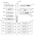
図6には、露光装置100のステージ制御に関連する制御系が一部省略して、ブロック図にて示されている。この制御系は、主制御装置20を中心として構成されている。主制御装置20は、CPU(中央演算処理装置)、ROM(リード・オンリ・メモリ)、RAM(ランダム・アクセス・メモリ)等からなるいわゆるマイクロコンピュータ(又はワークステーション)を含み、装置全体を統括して制御する。
FIG. 6 is a block diagram in which a part of the control system related to the stage control of the
上述のようにして構成された露光装置100では、デバイスの製造に際し、主制御装置20により、アライメント時移動領域内でウエハステージWST1,WST2上に保持されたウエハWに対して、アライメント系ALGを用いたウエハアライメント(例えば米国特許第4,780,617号明細書などに開示されるエンハンスト・グローバル・アライメント(EGA)など)が行われる。その際、エンコーダシステム71(エンコーダ711〜714)により、ウエハステージWST1,WST2の6自由度方向(X,Y,Z,θx,θy,θz)の位置情報が求められる(計測される)。
In the
ウエハアライメントの後、主制御装置20により、ウエハステージWST1、WST2は露光時移動領域に移動され、通常のスキャニング・ステッパと同様に、ウエハテーブルWTB1,WTB2上の基準マーク板FMの一対の第1基準マークとレチクルR上の対応する一対のレチクルアライメントマークとをレチクルアライメント系13A,13Bで検出するレチクルアライメント等が行われる。レチクルアライメントの手順については、例えば、米国特許第5,646,413号明細書などに開示されている。
After wafer alignment,
そして、主制御装置20により、ウエハアライメントの結果(EGAの結果得られたウエハW上の複数のショット領域の配列座標を基準マーク板FM上の第2基準マークの位置を基準に換算した配列座標)等に基づいて、ステップ・アンド・スキャン方式の露光動作が行われ、ウエハW上の複数のショット領域にレチクルRのパターンがそれぞれ転写される。ステップ・アンド・スキャン方式の露光動作は、レチクルステージRSTとウエハステージWST1,WST2との同期駆動を行う走査露光動作と、ウエハステージWST1,WST2をショット領域の露光のための加速開始位置に移動させるショット間移動(ステッピング)動作とを交互に繰り返すことで行われる。露光動作時には、エンコーダシステム70(エンコーダ701〜704)により、ウエハステージWST1,WST2の6自由度方向(X,Y,Z,θx,θy,θz)の位置情報が求められる(計測される)。
Then,
また、本実施形態の露光装置100は、2つのウエハステージWST1,WST2を備えている。そこで、一方のウエハステージ、例えばウエハステージWST1上にロードされたウエハに対してステップ・アンド・スキャン方式の露光を行うのと並行して、他方のウエハステージWST2上ではウエハ交換とその交換後のウエハに対するウエハアライメント(例えば米国特許出願公開第2008/0088843号明細書などに開示されるPri-BCHKの前半の処理同様の第2基準マークをアライメント系ALGを用いて検出する処理、及びEGA)を行う、並行処理動作が行われる。
Further, the
本実施形態の露光装置100では、前述の通り、主制御装置20は、露光時移動領域内ではエンコーダシステム70(図6参照)を用いて、アライメント時移動領域内ではエンコーダシステム71(図6参照)を用いて、ウエハテーブルWTB1,WTB2の6自由度方向(X,Y,Z,θx,θy,θz)の位置情報を求める(計測する)。
In the
ここで、エンコーダシステム70,71によるウエハテーブル(ウエハステージ)のXY平面内の3自由度方向(X軸方向,Y軸方向及びθz方向(X,Y,θz)とも略記する)の位置計測の原理などについてさらに説明する。ただし、ウエハテーブルWTB2(ウエハステージWST2)はウエハテーブルWTB1(ウエハステージWST1)と同様に構成されているので、ここではウエハテーブルWTB1(ウエハステージWST1)についてのみ説明する。
Here, the position measurement of the wafer table (wafer stage) in the XY plane in the three degrees of freedom direction (X-axis direction, Y-axis direction and θz direction (X, Y, θz)) is performed by the
本実施形態では、前述のようなエンコーダヘッド601〜604及びスケール板21の構成及び配置を採用したことにより、露光時移動領域内ではエンコーダヘッド601〜604のうちの少なくとも3つが、常時、スケール板21に対向する。
In the present embodiment, by employing the configuration and arrangement of the encoder heads 60 1 to 60 4 and
ウエハテーブルWTB1の中心(ウエハの中心に一致)が、露光時移動領域内の露光中心(投影光学系PLの光軸AXに一致)から+X側及び+Y側に位置する場合、ウエハテーブルWTB1上のヘッド604,601,602がスケール板21に対向する。この場合、これらのヘッド604,601,602(エンコーダ704,701,702)から有効な計測値が主制御装置20に送信される。なお、以下の説明において、ウエハテーブルWTB1の中心の位置(ウエハの中心位置)を、単に、ウエハテーブル(ウエハ)の位置と呼ぶ。
When the center of wafer table WTB1 (coincides with the center of the wafer) is located on the + X side and the + Y side from the exposure center (coincidence with optical axis AX of projection optical system PL) in the movement area during exposure, on wafer table WTB1 The heads 60 4 , 60 1 and 60 2 face the
同様に、ウエハテーブルWTB1が、露光中心(光軸AX)から−X側及び+Y側に位置する場合、ヘッド601,602,603がスケール板21に対向する。ウエハテーブルWTB1が、露光中心(光軸AX)から−X側及び−Y側に位置する場合、ヘッド602,603,604がスケール板21に対向する。ウエハテーブルWTB1が、露光中心Pから+X側及び−Y側に位置する場合、ヘッド603,604,601がスケール板21に対向する。さらに、ウエハテーブルWTB1が、露光中心(光軸AX)の極近傍に位置する場合、すべてのヘッド601〜604がスケール板21に対向する。スケール板21に対向しているヘッド(エンコーダ)から、有効な計測値が主制御装置20に送信される。
Similarly, wafer table WTB1 is, when located on the -X side and the + Y side from the exposure center (optical axis AX), the head 60 1, 60 2, 60 3 are opposed to the
主制御装置20は、ヘッド601〜604(エンコーダ701〜704)の計測結果に基づいて、ウエハテーブルWTB1(ウエハステージWST1)のXY平面内での位置(X,Y,θz)を算出する。ここで、エンコーダ701〜704の計測値(それぞれC1〜C4と表記する)は、ウエハテーブルWTB1の位置(X,Y,θz)に対して、次式(1)〜(4)のように依存する。
C1=−(cosθz+sinθz)X/√2
+(cosθz−sinθz)Y/√2+√2psinθz…(1)
C2=−(cosθz−sinθz)X/√2
−(cosθz+sinθz)Y/√2+√2psinθz…(2)
C3= (cosθz+sinθz)X/√2
−(cosθz−sinθz)Y/√2+√2psinθz…(3)
C4= (cosθz−sinθz)X/√2
+(cosθz+sinθz)Y/√2+√2psinθz…(4)
ただし、pは、図5に示されるように、ウエハテーブルWTB1(WTB2)の中心からのヘッドのX軸及びY軸方向に関する距離である。
C 1 = − (cos θz + sin θz) X / √2
+ (Cos θz−sin θ z) Y / √2 + √2 psin θz (1)
C 2 = − (cos θz−sin θz) X / √2
− (Cos θz + sin θz) Y / √2 + √2 psin θz (2)
C 3 = (cos θz + sin θz) X / √2
− (Cos θz−sin θz) Y / √2 + √2 psin θz (3)
C 4 = (cos θz−sin θz) X / √2
+ (Cos θz + sin θz) Y / √2 + √2 psin θz (4)
Here, p is a distance in the X-axis and Y-axis directions of the head from the center of wafer table WTB1 (WTB2), as shown in FIG.
主制御装置20は、ウエハテーブルWTB1(ウエハステージWST1)のXY平面内の位置に応じてスケール板21に対向する3つのヘッド(エンコーダ)を特定し、それらの計測値が従う式を上式(1)〜(4)から選択して連立方程式を組み、3つのヘッド(エンコーダ)の計測値を用いて連立方程式を解くことにより、ウエハテーブルWTB1のXY平面内での位置(X,Y,θz)を算出する。例えば、ウエハテーブルWTB1が露光中心(光軸AX)から+X側及び+Y側に位置する場合、主制御装置20は、ヘッド601,602,604(エンコーダ701,702,704)の計測値が従う式(1),(2),及び(4)から連立方程式を組み、それらの左辺に各ヘッドの計測値を代入して連立方程式を解く。なお、ウエハステージWST1が露光中心Pの極近傍に位置する場合、主制御装置20は、ヘッド601〜604(エンコーダ701〜704)から任意の3つを選択すれば良い。
主制御装置20は、上の算出結果(X,Y,θz)に基づいて、露光時移動領域内でウエハステージWST1を駆動(位置制御)する。
ウエハテーブルWTB1(ウエハステージWST1)が、アライメント時移動領域内に位置する場合、主制御装置20は、エンコーダシステム71を用いて3自由度方向(X,Y,θz)の位置情報を計測する。ここで、計測原理等は、露光中心がアライメント系ALGの検出中心に、スケール板21がスケール板22に置き換わる以外、先のエンコーダシステム70を用いる場合と同様である。
When wafer table WTB1 (wafer stage WST1) is positioned within the alignment movement region,
さらに、主制御装置20は、ウエハテーブルWTB1,WTB2(ウエハステージWST1,WST2)のX,Y平面内の位置に応じて、スケール板21,22に対向するヘッド601〜604のうちの3つを切り換えて使用する。ここで、エンコーダヘッドを切り換える際には、例えば米国特許出願公開第2008/0094592号明細書などに開示されているように、ウエハステージの位置計測結果の連続性を保証するためのつなぎ処理が行われる。
Furthermore, the
本実施形態の露光装置100では、ウエハステージWST1,WST2の軽量化及び位置制御性の向上等の観点から、ムービングコイル型の平面モータ30が採用されている。ムービングコイル型の平面モータ30の場合、ステージベース12内に設けられた固定子(磁石ユニット14a)により、例えば図7(A)に示されるように、露光装置100内に定常的な開放磁場が放出される。図7(A)では、開放磁場の力線(磁力線)が点線(破線)で示されている。
In the
投影ユニットPU、アライメント系ALG等の露光装置100の構成各部(ステージ装置を除く)を支持するメインフレーム(メトロロジーフレーム)23は、通常その素材として磁性体であるインバーが用いられる。勿論、セラミックス等の非磁性体をメインフレームの素材として用いることもできるが、メインフレームに支持される構成各部の全てを非磁性体とすることはほぼ不可能である。このため、磁石ユニット14aにより放出される開放磁場が媒体となってステージベース12とメインフレーム23(支持される構成各部を含む)との間に磁力が作用し、この磁力の作用によりメインフレーム23が極めて微量ではあるが歪み得る。このメインフレーム23の歪みにより、スケール板21,22の姿勢が変わる、あるいはスケール板21,22自体が歪み、結果的にエンコーダシステム70,71の計測誤差が発生し得る。
The main frame (metrology frame) 23 that supports the constituent parts (excluding the stage apparatus) of the
さらに、ウエハステージWST1,WST2も、永久磁石等の磁性体を含むZ・チルト駆動機構28等を含んで構成されている。また、平面モータ30を構成する可動子(コイルユニット(不図示))、またZ・チルト駆動機構28のコイルも磁場を発生する。このため、ウエハステージWST1,WST2がステージベース12上を移動することにより開放磁場が変化し、メインフレーム23(支持される構成各部を含む)に作用する磁力がウエハステージWST1,WST2の位置に応じて変わり得る。
Further, wafer stages WST1 and WST2 are also configured to include a Z /
図7(B)には、図7(A)と同様に、露光装置100内の開放磁場が示されている。図7(A)及び図7(B)は、ウエハステージWST2がアライメント時移動領域内で−X方向に移動することにより、ウエハステージWST1は露光時移動領域内のほぼ同じ位置にあるにもかかわらず、露光時移動領域内の開放磁場が図7(A)に示される状態から図7(B)に示される状態に変化する様子が示されている。この開放磁場の変化は、上述の通り、スケール板21の姿勢の変化あるいはスケール板21自体の歪みを生じさせる。上記と反対に、ウエハステージWST1が移動すると、ウエハステージWST2が停止していても、アライメント時移動領域内の磁場が変化し、スケール板22の姿勢の変化あるいはスケール板22自体の歪みを生じさせる。
FIG. 7B shows an open magnetic field in the
従って、一方のウエハステージの位置に応じて、他方のウエハテーブル(ウエハステージ)の位置を計測するエンコーダシステム70又は71の計測誤差が発生し得る。この計測誤差は、露光精度及びアライメント計測精度の低下を招き、ひいては重ね合わせ精度、フォーカス精度等が低下し、最終的には、半導体デバイスの歩留まりの低下をも招くこととなる。
Accordingly, a measurement error of the
以下、一方のウエハステージの移動に伴う磁場の変化に起因する他方のウエハテーブル(ウエハステージ)の位置を計測するエンコーダシステム70,71の計測誤差を補正する方法について説明する。
Hereinafter, a method of correcting the measurement error of the
主制御装置20により、露光装置100の起動時、アイドル時等に、エンコーダシステム70,71の計測誤差を補正するための補正マップが作成される。ここで、エンコーダシステム70用の補正マップは、以下の手順により作成される。なお、以下の補正マップの作成に関する説明中では、エンコーダシステム70によるウエハステージの位置の計測情報を(X,Y)とし、エンコーダシステム71によるウエハステージの位置の計測情報を(x,y)として、説明を行う。
The
ウエハテーブルWTB1(ウエハステージWST1)上には、テストウエハWT(図8(B)参照)がロードされているものとする。テストウエハWTの表面には、露光装置100にインライン接続された不図示のコータ・デベロッパ(C/D)によりレジストが塗布されている。 It is assumed that a test wafer W T (see FIG. 8B) is loaded on wafer table WTB1 (wafer stage WST1). On the surface of the test wafer W T, the resist is applied by coater developer inline (not shown) connected to the exposure apparatus 100 (C / D).
主制御装置20は、テストウエハWTがロードされたウエハテーブルWTB1上の基準マーク板FMが投影光学系PLの直下(露光中心(投影光学系PLの光軸AXと一致))に位置するよう、ウエハステージWST1を移動させる。このとき、ウエハステージWST2は、ウエハステージWST1から十分に離れた基準位置(x0、y0)、例えば、ウエハの交換が行われるロード・アンロード位置に位置しているものとする。
The
また、主制御装置20は、レチクル交換機構(不図示)を用いて、テストレチクルRTをレチクルステージRST上にロードする。テストレチクルRTには、矩形のパターン領域が形成され、その中央部に図8(A)に示されるような十字状の遮光パターン(又は開口パターン)から成るテストパターンMRが形成されている。また、テストレチクルRTには、レチクルセンタを通るパターン領域のX軸方向の両側に、一対のレチクルアライメントマーク(不図示)が形成されている。
Further,
テストレチクルRTのロード後、主制御装置20は、一対のレチクルアライメント系13A,13B及びウエハステージWST1の基準マーク板FMを用いて、前述と同様にしてテストレチクルRTのレチクルアライメントを行う。一対のレチクルアライメント系13A,13Bにより対応するレチクルアライメントマークと第1基準マークとが検出される状態で、主制御装置20は、エンコーダシステム70からの位置計測結果(X1,Y1,θz1)をリセットする。なお、以下のテスト露光中、レチクルステージRST(テストレチクルRT)は、その位置決め位置に留められる。
After loading test reticle RT ,
次に、主制御装置20は、ウエハテーブルWTB1の中心(テストウエハWTの中心)が投影光学系PLの下方(露光中心の近傍)に位置するよう、ウエハステージWST1を移動する。なお、この時のウエハステージWST1の位置を、露光時移動領域内の第1計測点での基準位置(X10,Y10)とする。移動後、主制御装置20は、エンコーダシステム70からの計測情報X,Yが一定に維持されるように、ウエハステージWST1をサーボ制御して、その位置決め状態を維持する(その位置に留める)。ただし、ウエハステージWST1のθz1方向の位置はリセット時の位置に維持されている。
Next,
上述の状態において、主制御装置20は、照明光ILをテストレチクルRTに照射して、テストパターンMRの像をテストウエハWTに転写する。
In the above state, the
転写後、主制御装置20は、ウエハステージWST1を−X方向に距離H、ステップ駆動する。このとき、主制御装置20は、エンコーダシステム70からの計測情報X,Yではなく、ウエハ干渉計システム18からの計測情報に基づいて、ウエハステージWST1をステップ駆動する。ステップ駆動の後、主制御装置20は、エンコーダシステム70からの計測情報X,Yが一定に維持されるようにサーボ制御して、その位置決め状態を維持する(その位置に留める)。ただし、ウエハステージWST1のθz1方向の位置はリセット時の位置に維持されている。この状態において、主制御装置20は、ウエハステージWST2をアライメント時移動領域内の第1計測位置(x1,y1)に移動させる。
After the transfer,
上述の状態において、主制御装置20は、先と同様に、照明光ILをテストレチクルRTに照射して、テストパターンMRの像をテストウエハWTに転写する。
In the above state, the
以降同様に、主制御装置20は、ウエハステージWST1を−X方向に距離Hステップ駆動し、エンコーダシステム70からの計測情報X,Yが一定に維持されるように、ウエハステージWST1をサーボ制御してその位置決め状態を維持している間に、ウエハステージWST2をアライメント時移動領域内の次の計測位置(xi+1,yi+1)に移動するとともに、テストパターンMRの像をテストウエハWTに転写する。この処理を、ウエハステージWST2をアライメント時移動領域内の計測位置(x2,y2)〜(xI、yI)への逐次移動に対して繰り返す。
Thereafter, similarly,
これにより、図8(B)及び図8(C)に示されるように、テストパターンMRに対応する(I+1)個の潜像(M10〜M1I)が、テストウエハWTの中央にX軸方向に並んで形成される。
Thus, as shown in FIG. 8 (B) and FIG. 8 (C), the corresponding test pattern M R (I + 1) pieces of the
なお、ステップ距離Hは、露光時移動領域内の計測点間の離間距離に対して十分小さく、例えば100μm程度に、選ぶこととする。 Note that the step distance H is selected to be sufficiently small, for example, about 100 μm with respect to the separation distance between the measurement points in the moving area during exposure.
露光時移動領域内の第1計測点(X1i,Y1i)(i=0〜i)におけるテスト露光が終了すると、続いて、主制御装置20は、露光時移動領域内の第2計測点(X2i,Y2i)(i=0〜i)におけるテスト露光を開始する。ここで、第2計測点は、その基準位置(X20,Y20)が、図8(B)に示されるウエハテーブルWTB1の中心(テストウエハWTの中心)から+X方向に距離HXの点が投影光学系PLの下方(露光中心の近傍)に位置するウエハテーブルWTB1(ウエハステージWST1)の位置である。
When the test exposure at the first measurement point (X 1i , Y 1i ) (i = 0 to i) in the movement area at the time of exposure is completed, the
露光時移動領域内の第2計測点(X2i,Y2i)(i=0〜i)におけるテスト露光に際しては、まず、主制御装置20は、ウエハステージWST1を、ウエハ干渉計システム18からの計測情報に基づいて、第2計測点の基準位置(X20,Y20)に移動させる。それと同時に、主制御装置20は、ウエハステージWST2を基準位置(x0,y0)に移動させる。移動後、主制御装置20は、エンコーダシステム70からの計測情報X,Yが一定に維持されるように、ウエハステージWST1をサーボ制御して、その位置状態を維持する。ただし、ウエハステージWST1のθz1方向の位置はリセット時の位置に維持されている。
At the time of test exposure at the second measurement point (X 2i , Y 2i ) (i = 0 to i) in the movement area during exposure, first,
上述の状態において、主制御装置20は、照明光ILをテストレチクルRTに照射して、テストパターンMRの像をテストウエハWTに転写する。
In the above state, the
以降同様に、主制御装置20は、ウエハステージWST1を−X方向に距離H、ステップ駆動し、エンコーダシステム70からの計測情報X,Yが一定に維持されるようにウエハステージWST1をサーボ制御してその位置決め状態を維持している間に、ウエハステージWST2をアライメント時移動領域内の次の計測位置(xi+1,yi+1)に移動するとともに、テストパターンMRの像をテストウエハWTに転写する。この処理を、ウエハステージWST2をアライメント時移動領域内の計測位置(x1,y1)〜(xI、yI)への逐次移動に対して繰り返す。
Thereafter, similarly,
これにより、図8(B)に示されるように、テストパターンMRに対応する(I+1)個の潜像(M20〜M2I)が、テストウエハWTの+X端近傍にX軸方向に並んで形成される。
Thus, as shown in FIG. 8 (B), corresponding to the test pattern M R (I + 1) pieces of the
以後、主制御装置20は、同様のテスト露光を露光時移動領域内の第3〜5計測点(X3i,Y3i)〜(X5i,Y5i)(i=0〜i)について行う。ここで、第3〜5計測点は、それぞれの基準位(X30,Y30)、(X40,Y40)、(X50,Y50)が、図8(B)に示されるウエハテーブルWTB1の中心(テストウエハWTの中心)から+Y方向に距離HYの点、−X方向に距離HXの点、及び−Y方向に距離HYの点が投影光学系PLの下方(露光中心の近傍)に位置するウエハステージWST1の位置である。これにより、図8(B)に示されるように、テストパターンMRに対応する潜像(M30〜M3I、M40〜M4I、及びM50〜M5I)が、テストウエハWTの+Y端近傍、−X端近傍、及び−Y端近傍にX軸方向に並んで形成される。
Thereafter, the
テスト露光の終了後、主制御装置20は、ウエハステージWST1をロード・アンロード位置に移動し、ウエハステージWST1からテストウエハWTをアンロードする。主制御装置20は、テストウエハWTを、前述のC/D(不図示)に搬送して現像する。これにより、テストウエハWT上に、図8(B)に示されるように、レジストパターンM10〜M1I、M20〜M2I、M30〜M3I、M40〜M4I、及びM50〜M5Iが形成される。主制御装置20は、現像されたテストウエハWTを、ロード・アンロード位置に待機しているウエハステージWST1に再度ロードし、ウエハステージWST1をアライメント時移動領域に移動する。なお、この時、ウエハステージWST2は、露光時移動領域等に退避している。
After the test the end of exposure,
上述のテストウエハWTの現像後、主制御装置20は、アライメント系ALGを用いてテストウエハWTに形成されたレジストパターンを検出する。
After development of the above-mentioned test wafer W T, the
主制御装置20は、テストウエハWTの中央に形成されたレジストパターンM10がアライメント系ALGの検出視野内に位置するよう、ウエハステージWST1を移動する。主制御装置20は、アライメント系ALGの検出中心(指標中心)にレジストパターンM10を一致させ、ウエハステージWST1を位置決めする。この時の指標中心からのレジストパターンM10のX軸方向及びY軸方向に関する位置ずれΔX10,ΔY10は、ΔX10=ΔY10=0と検出される。主制御装置20は、検出された位置ずれΔX10,ΔY10をレジストパターンM10に対応するテスト露光時のウエハステージWST1の位置(露光時移動領域内の第1計測点の位置(X1,Y1))とウエハステージWST2の位置(アライメント時移動領域内の基準位置x0,y0)とに対応付けて、記憶装置(不図示)に記憶する。ここで、第1計測点の位置(X1,Y1)は、先に説明した第1計測点における基準位置(X10,Y10)と同じである。
The
主制御装置20は、アライメント系ALGの検出中心(指標中心)とレジストパターンM10が一致した上の状態から、ウエハステージWST1を−X方向に距離Hステップ駆動する。この場合も、エンコーダシステム71からの計測情報X2,Y2ではなく、ウエハ干渉計システム18からの計測情報に基づいてウエハステージWST1をステップ駆動するのが望ましい。ステップ駆動後、主制御装置20は、アライメント系ALGを用いてレジストパターンM11を検出し、その指標中心からのX軸方向及びY軸方向に関する位置ずれΔX11,ΔY11を検出する。
The
ここで、テスト露光時に、ウエハステージWST2の位置に応じた磁場の変化に起因するエンコーダシステム70の計測誤差が発生していなければ、位置ずれはΔX11=ΔY11=0と検出される。しかし、図8(C)に示される例では、位置ずれはΔX11≠0,ΔY11≠0と検出される。なお、図中、レジストパターンM11(〜M1I)の検出時における指標マークの位置が、破線を用いて、レジストパターンとともに示されている。検出された位置ずれは、ウエハステージWST2の位置に応じた磁場の変化に起因するエンコーダシステム70の計測誤差を意味する。
Here, at the time of test exposure, if no measurement error of the
主制御装置20は、検出された位置ずれΔX11,ΔY11をレジストパターンM11に対応するテスト露光時のウエハステージWST1の位置(露光時移動領域内の第1計測点の位置(X1,Y1))とウエハステージWST2の位置(アライメント時移動領域内の基準位置(x0,y0))とに対応付けて、記憶装置(不図示)に記憶する。
The
以降、主制御装置20は、同様に、逐次、ウエハステージWST1を−X方向に距離Hステップ駆動し、アライメント系ALGを用いてレジストパターンM1i(i=2〜I)を検出する。検出毎に、主制御装置20は、レジストパターンM1i(i=2〜I)の指標中心からの位置ずれΔX1i,ΔY1i(i=2〜I)の検出結果を、レジストパターンM1iに対応するテスト露光時のウエハステージWST1の位置(露光時移動領域内の第1計測点の位置(X1,Y1)とウエハステージWST2の位置(アライメント時移動領域内の基準位置x0,y0)とに対応付けて、記憶装置(不図示)に記憶する。
Thereafter,
主制御装置20は、同様に、その他のレジストパターンM20〜M2I、M30〜M3I、M40〜M4I、及びM50〜M5Iを検出する。ここで、テスト露光時に、ウエハステージWST1の位置に応じた磁場の変化に起因するエンコーダシステム70の計測誤差が発生していなければ、ウエハステージWST2の位置が互いに等しいレジストパターンM1i〜M5iのそれぞれについての位置ずれΔXi,ΔYi(i=1〜I)が検出される。計測誤差が発生している場合、異なる位置ずれΔXki,ΔYki(k=1〜5、i=1〜I)が検出される。これにより、補正マップΔXi,ΔYiが、Xk,Yk,xi,yiについての関数ΔXi(Xk,Yk,xi,yi),ΔYi(Xk,Yk,xi,yi)として求められる。
なお、補正マップΔXi(Xk,Yk,xi,yi),ΔYi(Xk,Yk,xi,yi)はXk,Yk,xi,yiの複数の離散点についての離散データとして求められるので、線形補完等を用いてX,Y,x,yについての連続関数に変換しても良い。すなわち、補正情報を補正マップではなく、補正関数ΔXi(X,Y,x,y),ΔYi(X,Y,x,y)の形で持っておいても良い。 The correction maps ΔX i (X k , Y k , x i , y i ) and ΔY i (X k , Y k , x i , y i ) are a plurality of X k , Y k , x i , y i . Since it is calculated | required as discrete data about a discrete point, you may convert into the continuous function about X, Y, x, y using linear complementation etc. That is, the correction information may be held in the form of correction functions ΔX i (X, Y, x, y), ΔY i (X, Y, x, y) instead of the correction map.
主制御装置20は、露光時にウエハステージWST1を露光時移動領域内で駆動する際、エンコーダシステム70,71からのウエハステージWST1,WST2の位置計測情報X,Y,x,yを用いて補正マップΔXi(Xk,Yk,xi,yi),ΔYi(Xk,Yk,xi,yi)から補正値ΔXi,ΔYiを導出し、該補正値を用いてエンコーダシステム70からのウエハステージWST1の位置計測情報X,YをそれぞれX−ΔXi,Y−ΔYiと補正する。主制御装置20は、補正した位置計測情報X−ΔXi,Y−ΔYiを用いて、ウエハステージWST1を駆動(位置制御)する。
エンコーダシステム71用の補正マップは、形成位置が既知の複数のマークが設けられた基準ウエハW0を用いて、以下の手順により作成される。
Correction map for an
図9には、基準ウエハW0の一例が示されている。基準ウエハW0上には、5つの十字マークAM1〜AM5が形成されている。ここで、マークAM1〜AM5は、それぞれ、基準ウエハW0の中心、中心から+X方向に距離WXの位置、中心から+Y方向に距離WYの位置、中心から−X方向に距離WXの位置、中心から−Y方向に距離WYの位置に形成されている。基準ウエハW0は、ウエハテーブルWTB2(ウエハステージWST2)上にロードされているものとする。 Figure 9 shows an example of a reference wafer W 0 is shown. On the reference wafer W 0 is five cross marks AM 1-Am 5 are formed. Here, the marks AM 1 to AM 5 are respectively the center of the reference wafer W 0 , the position of the distance WX in the + X direction from the center, the position of the distance WY in the + Y direction from the center, and the position of the distance WX in the −X direction from the center. , At a distance WY in the −Y direction from the center. Reference wafer W 0 is assumed to be loaded on the wafer table WTB2 (wafer stage WST2).
主制御装置20は、基準ウエハW0がロードされたウエハステージWST2をアライメント時移動領域内に移動させる。また、主制御装置20は、ウエハステージWST1を、ウエハステージWST2から十分に離間させた基準位置(X0,Y0)に移動させる。
The
次に、主制御装置20は、基準ウエハW0に形成されたマークAM1がアライメント系ALGの検出視野内に位置するよう、ウエハステージWST2を移動させる。主制御装置20は、アライメント系ALGの検出中心(指標中心)にマークAM1を一致させる。この時のウエハステージWST2の位置を、アライメント時移動領域内の第1計測位置x1,y1と定める。この時の指標中心からのマークAM1のX軸方向及びY軸方向に関する位置ずれΔx10,Δy10は、Δx10=Δy10=0と検出される。主制御装置20は、検出された位置ずれΔx10,Δy10をウエハステージWST1の位置(露光時移動領域内の基準位置X0,Y0)とウエハステージWST2の位置(アライメント時移動領域内の第1計測位置x1,y1)とに対応付けて、記憶装置(不図示)に記憶する。
Next,
主制御装置20は、エンコーダシステム71からの計測情報(x,y)に基づいて、ウエハステージWST2をサーボ制御し、その位置決め状態を維持する(その位置(x1,y1)に留める)。ただし、ウエハステージWST2のθz方向の位置は基準位置(θz=0)に維持されている。
上述の状態において、主制御装置20は、ウエハステージWST1を露光時移動領域内の第1計測位置X1,Y1に移動する。移動後、主制御装置20は、アライメント系ALGを用いてマークAM1を検出し、その指標中心からのX軸方向及びY軸方向に関する位置ずれΔx11,Δy11を検出する。
In the above-described state,
ここで、ウエハステージWST1の位置に応じた磁場の変化に起因するエンコーダシステム71の計測誤差が発生している場合、位置ずれはΔx11≠0,Δy11≠0と検出される。主制御装置20は、検出された位置ずれΔx11,Δy11を、ウエハステージWST1の位置(露光時移動領域内の第1計測位置X1,Y1)とウエハステージWST2の位置(アライメント時移動領域内の第1計測位置x1,y1)とに対応付けて、記憶装置(不図示)に記憶する。
Here, when a measurement error of the
以降、主制御装置20は、同様に、逐次、ウエハステージWST1を露光時移動領域内の計測位置Xi,Yi(i=2〜I)に移動し、アライメント系ALGを用いてマークAM1を検出する。検出毎に、主制御装置20は、マークAM1の指標中心からの位置ずれΔx1i,Δy1i(i=2〜I)の検出結果を、ウエハステージWST1の位置(露光時移動領域内の第1計測位置Xi,Yi)とウエハステージWST2の位置(アライメント時移動領域内の第1計測位置x1,y1)とに対応付けて、記憶装置(不図示)に記憶する。
Thereafter,
主制御装置20は、同様に、その他のマークAMj(j=2〜5)を検出する。ここで、ウエハステージWST2の位置に応じた磁場の変化に起因するエンコーダシステム71の計測誤差が発生していなければ、ウエハステージWST1の位置が互いに等しいマークAMj(j=1〜5)のそれぞれについての位置ずれΔxi,Δyi(i=1〜I)が検出される。計測誤差が発生している場合、異なる位置ずれΔXjj,ΔYjj(j=1〜5、i=1〜I)が検出される。
Similarly,
主制御装置20は、マークAMjの指標中心からの位置ずれΔXjj,ΔYjj(j=2〜5)の検出結果を、ウエハステージWST1の位置(露光時移動領域内の計測位置Xi,Yi)とウエハステージWST2の位置(アライメント時移動領域内の計測位置xj,yj)とに対応付けて、記憶装置(不図示)に記憶する。これにより、補正マップΔxi,Δyiが、Xi,Yi,xj,yjについての関数Δxi(Xi,Yi,xj,yj),Δyi(Xi,Yi,xj,yj)として求められる。
The
なお、補正マップΔxi(Xi,Yi,xj,yj),Δyi(Xi,Yi,xj,yj)はXi,Yi,xj,yjの複数の離散点についての離散データとして求められるので、線形補完等を用いてX,Y,x,yについての連続関数に変換しても良い。すなわち、補正情報を補正マップではなく、補正関数Δxi(X,Y,x,y),Δy(X,Y,x,y)の形で持っておいても良い。 The correction maps Δx i (X i , Y i , x j , y j ) and Δy i (X i , Y i , x j , y j ) are a plurality of X i , Y i , x j , y j . Since it is calculated | required as discrete data about a discrete point, you may convert into the continuous function about X, Y, x, y using linear complementation etc. That is, the correction information may be held in the form of correction functions Δx i (X, Y, x, y), Δy (X, Y, x, y) instead of the correction map.
主制御装置20は、アライメント計測時にウエハステージWST2をアライメント時移動領域内で駆動する際、エンコーダシステム70,71からのウエハステージWST1,WST2の位置計測情報X,Y,x,yを用いて補正マップΔxi(Xi,Yi,xj,yj),Δyi(Xi,Yi,xj,yj)から補正値Δxi,Δyiを導出し、該補正値を用いてエンコーダシステム71からのウエハステージWST2の位置計測情報x,yをそれぞれx−Δxi,y−Δyiと補正する。主制御装置20は、補正した位置計測情報x−Δxi,y−Δyiを用いて、ウエハステージWST2を駆動(位置制御)する。
なお、本実施形態では露光時移動領域内の5つの計測位置及びアライメント時移動領域内のI+1の計測位置(基準位置を含む)を選択したが、補正マップの作成に費やす時間、要する補正精度等より、計測位置の数及び位置を定めることとする。 In this embodiment, five measurement positions in the movement area during exposure and I + 1 measurement positions (including the reference position) in the movement area during alignment are selected. However, the time required for creating the correction map, the correction accuracy required, and the like Therefore, the number and positions of measurement positions are determined.
本実施形態の露光装置100では、両ウエハステージWST1,WST2は同様に構成されているので、補正マップΔXi(Xk,Yk,xi,yi),ΔYi(Xk,Yk,xi,yi)及びΔxi(Xi,Yi,xj,yj),Δyi(Xi,Yi,xj,yj)は両方のウエハステージWST1,WST2に対して兼用することができる。なお、ウエハステージWST1,WST2間の個体差がある場合、両ステージのそれぞれに対して補正マップを作成することとする。作成手順は、ウエハステージWST1,WST2が入れ替わる以外、上述の手順と同様である。
In
なお、本実施形態では、一方のウエハステージの移動に伴う磁場の変化に起因する他方のウエハステージについてのエンコーダシステム70,71の計測誤差に注目しているため、補正マップを作成するに際し、一方のウエハステージを、逐一、計測位置に位置決めすることとした。ここで、一方のウエハステージを、各計測位置から、例えば単位加速度(単位駆動力)でX軸方向及びY軸方向のそれぞれに駆動することとしても良い。この場合、一方のウエハステージの移動に伴う雰囲気中の圧力変動等、力学的効果に起因する他方のウエハステージについてのエンコーダシステム70,71の計測誤差を補正することのできる補正マップが得られる。
In the present embodiment, attention is paid to the measurement error of the
次に、エンコーダシステム70,71による3自由度方向(Z,θx,θy)の位置計測の原理などについてさらに説明する。
Next, the principle of position measurement in the three degrees of freedom direction (Z, θx, θy) by the
本実施形態では、前述のようなエンコーダヘッド601〜604及びスケール板21の構成及び配置を採用したことにより、露光時移動領域内では、ウエハステージWST1(WST2)の位置に応じて、エンコーダヘッド601〜604のうちの少なくとも3つがスケール板21に対向する。スケール板21に対向するヘッド(エンコーダ)から有効な計測値が主制御装置20に送信される。
In the present embodiment, by employing the configuration and arrangement of the encoder heads 60 1 to 60 4 and
主制御装置20は、エンコーダ701〜704の計測結果に基づいて、ウエハテーブルWTB1(WTB2)の位置(Z,θx,θy)を算出する。ここで、エンコーダ701〜704のZ軸方向に関する計測値(前述のXY平面内の一軸方向についての計測値C1〜C4と区別して、それぞれ、D1〜D4と表記する)は、ウエハテーブルWTB1(WTB2)の位置(Z,θx,θy)に対して、次式(5)〜(8)のように依存する。
The
D1=−ptanθy+ptanθx+Z …(5)
D2= ptanθy+ptanθx+Z …(6)
D3= ptanθy−ptanθx+Z …(7)
D4=−ptanθy−ptanθx+Z …(8)
ただし、pは、ウエハテーブルWTB1(WTB2)の中心からのヘッドのX軸及びY軸方向に関する距離(図5参照)である。
D 1 = −ptan θy + ptan θx + Z (5)
D 2 = ptan θy + ptan θx + Z (6)
D 3 = ptan θy−ptan θx + Z (7)
D 4 = −ptan θy−ptan θx + Z (8)
However, p is the distance (refer FIG. 5) regarding the X-axis and Y-axis directions of the head from the center of wafer table WTB1 (WTB2).
主制御装置20は、ウエハテーブルWTB1(WTB2)の位置に応じて3つのヘッド(エンコーダ)の計測値の従う式を上式(5)〜(8)から選択し、それらから構成される連立方程式に3つのヘッド(エンコーダ)の計測値を代入して解くことにより、ウエハテーブルWTB1(WTB2)の位置(Z,θx,θy)を算出する。例えば、ウエハテーブルWTB1(WTB2)が露光中心(光軸AX)から+X側及び+Y側に位置する場合、主制御装置20は、ヘッド601,602,604(エンコーダ701,702,704)の計測値が従う式(5),(6),及び(8)から連立方程式を組み、それらの左辺に計測値を代入して解く。ウエハテーブルWTB1(WTB2)の位置(Z,θx,θy)の算出は、先に説明したようにウエハアライメント時のフォーカスマッピングの際、及び露光の際に行われる。
主制御装置20は、事前に取得したウエハの凹凸情報と、上記の算出結果(Z,θx,θy)とに基づいて、露光時移動領域内でウエハテーブルWTB1(WTB2)をフォーカス・レベリング制御する。
ウエハテーブルWTB1(WTB2)が、アライメント時移動領域内に位置する場合、主制御装置20は、エンコーダシステム71を用いて3自由度方向(Z,θx,θy)の位置情報を計測する。この場合の計測原理等は、露光中心がアライメント系ALGの検出中心に、スケール板21がスケール板22に置き換わる以外、先のエンコーダシステム70を用いる場合と同様である。主制御装置20は、エンコーダシステム71の計測結果に基づいて、露光時のフォーカス・レベリング制御のため、ウエハの面位置とウエハテーブルWTB1(WTB2)のZ位置との関係を取得する。
When wafer table WTB1 (WTB2) is located in the movement region during alignment,
さらに、主制御装置20は、ウエハステージWST1,WST2の位置に応じて、スケール板21,22に対向するヘッド601〜604のうちの3つを切り換えて使用する。ここで、エンコーダヘッドを切り換える際には、ウエハテーブルWTB1(WTB2)の位置の計測結果の連続性を保証するため、前述と同様のつなぎ処理が行われる。
Further,
エンコーダシステム70,71によるウエハテーブルWTB1(WTB2)の3自由度方向(Z,θx,θy)の位置計測においても、主制御装置20は、前述と同様に、補正マップを作成し、その補正マップを用いてエンコーダシステム70,71からのウエハテーブルWTB1(WTB2)の3自由度方向(Z,θx,θy)の位置計測情報を補正し、その補正した位置計測情報を用いて、例えば前述のフォーカス・レべリング制御などを行うことができる。
In the position measurement in the three-degree-of-freedom directions (Z, θx, θy) of wafer table WTB1 (WTB2) by
ただし、主制御装置20は、エンコーダシステム70用の補正マップを作成するに際し、エンコーダシステム70の少なくとも3つのエンコーダでウエハテーブルWTB1のZ位置を計測しながら、ウエハテーブルWTB1のZ位置を変更してフォーカス計測マークをウエハ上に転写し、そのウエハの現像後にレジストパターンを検出することで、マークのフォーカス情報(ウエハテーブルのZ軸方向の位置)を計測する。また、エンコーダシステム71用の補正マップを作成するに際し、アライメント時移動領域内(アライメント系ALG近傍)に設置された多点AF系AFを用いてウエハテーブルのZ軸方向の位置を計測する。
However,
以上説明したように、本実施形態の露光装置100によると、主制御装置20により、エンコーダシステム70で計測された一方のウエハステージWST1(又はWST2)の位置情報と、両方のウエハステージWST2及びWST1の位置に応じた補正情報(予め作成した補正マップ又は補正関数)とに基づいて、露光時移動領域内で、平面モータ30を介して一方のウエハステージWST1(又はWST2)が駆動される。ここで、補正マップ等から補正値を取り出すためのウエハステージWST2、WST1の位置情報は、エンコーダシステム71、70で計測された位置情報が用いられる。従って、露光時移動領域内では、一方のウエハステージWST1(又はWST2)を高精度に駆動することが可能となる。
As described above, according to the
また、主制御装置20により、エンコーダシステム71で計測された他方のウエハステージWST2(又はWST1)の位置情報と、両方のウエハステージWST2及びWST1の位置に応じた補正情報(予め作成した補正マップ又は補正関数)とに基づいて、アライメント時移動領域内で、平面モータ30を介して他方のウエハステージWST2(又はWST1)が駆動される。ここで、補正マップ等から補正値を取り出すためのウエハステージWST2、WST1の位置情報は、エンコーダシステム71、70で計測された位置情報が用いられる。従って、アライメント時移動領域内では、他方のウエハステージWST2(又はWST1)を高精度に駆動することが可能となる。本実施形態では、補正情報は、6自由度方向に関して求められている。
The
従って、本実施形態の露光装置100によると、アライメント時における高いアライメント計測精度及びフォーカスマッピング精度を確保することができ、これらの結果を用いて露光が行われるので、高い露光精度(重ね合わせ精度、フォーカス制御精度等)を実現して、最終的には、半導体デバイスの歩留まりを向上させることが可能となる。
Therefore, according to the
なお、上記実施形態では、エンコーダシステム70の補正マップ又は補正関数の作成のため、テストパターンMRの像をテストウエハWTに転写し、その転写像の位置計測を行うことで、補正マップ又は補正関数の作成のためのデータΔXki,ΔYki(k=1〜5、i=1〜I)を求める場合について説明したが、これに限らず、ウエハテーブルに少なくともその一部(空間像計測用スリットを含む)が配置された空間像計測装置を設け、該空間像計測装置を用いて、テストパターンMRの像を計測し、その空間像計測により得られる横軸をエンコーダシステム70の計測情報とする空間像プロファイルからテストパターンMRの像の結像位置を求めることで、上記のデータΔXki,ΔYki(k=1〜5、i=1〜I)を求めても良い。
In the above embodiment, since the creation of the correction map or the correction function of the
また、露光装置が上述の空間像計測装置を備えている場合、例えば、その空間像計測用スリット(以下、スリットと称する)を複数、例えば少なくともウエハステージWST1のウエハテーブルWTB1の四隅を含む複数箇所に配置して、それぞれのスリットでテストパターンの空間像を計測可能にすることができる。この場合、主制御装置20は、ウエハステージWST1(ウエハテーブルWTB1)を駆動して複数のスリットを順次に投影光学系PLの下方に位置させ、その都度、ウエハステージWST2を上記実施形態と同様にアライメント時移動領域内の複数箇所に順次位置決めし、位置決め位置毎に、投影光学系PLの下方に位置するスリットを用いて、テストパターンの空間像計測を、ウエハテーブルWTB1の位置をエンコーダシステム70で計測しつつ、スリットスキャン方式で行っても良いし、あるいは、主制御装置20は、ウエハステージWST2を上記実施形態と同様にアライメント時移動領域内の複数箇所に順次位置決めし、位置決め位置毎に、ウエハステージWST1(ウエハテーブルWTB1)を駆動して複数のスリットを順次に投影光学系PLの下方に位置させて、テストパターンの空間像計測を、ウエハテーブルWTB1の位置をエンコーダシステム70で計測しつつ、スリットスキャン方式で行っても良い。いずれにしても、計測されたテストパターンの空間像のプロファイルから求められるテストパターンの像の結像位置を求めることで、上記のデータΔXki,ΔYki(k=1〜5、i=1〜I)を求めることができる。
When the exposure apparatus includes the above-described aerial image measurement device, for example, a plurality of aerial image measurement slits (hereinafter referred to as slits), for example, a plurality of locations including at least four corners of wafer table WTB1 of wafer stage WST1. The aerial image of the test pattern can be measured with each slit. In this case,
同様に、上記実施形態と同様に、テストパターンMRの像をテストウエハWTに転写し、その転写像の位置計測を行う場合であっても、ウエハステージWST2をアライメント時移動領域内の複数の位置に位置決めする都度、ウエハテーブルWTBを露光時移動領域内の複数位置に位置決めし、位置決め位置毎にテストパターンMRの像をテストウエハWTに転写しても良い。 Similarly, as in the above embodiment, the images were transferred to the test pattern M R to the test wafer W T, even when performing position measurement of the transferred image, a plurality of time alignment to wafer stage WST2 movement area each time be positioned in the position to position the wafer table WTB in a plurality of positions of the exposure time movement area, it may be transferred to an image of the test pattern M R to the test wafer W T for each positioning position.
また、上記実施形態では、計測位置とは別に基準位置を定め、基準位置におけるマークの位置の実測値を基準として、各計測位置におけるマーク位置の差を求めるものとしたが、これに限らず、複数の計測位置の1つにおけるマークの位置の実測値を基準として、残りの各計測位置におけるマーク位置の差を求めることとしても良い。 In the above embodiment, the reference position is determined separately from the measurement position, and the difference between the mark positions at each measurement position is obtained based on the actual measurement value of the mark position at the reference position. The difference between the mark positions at the remaining measurement positions may be obtained with reference to the actual measurement value of the mark position at one of the plurality of measurement positions.
また、上記実施形態では、主としてエンコーダシステム70,71を用いてウエハステージWST1,WST2の位置情報を計測し、ウエハステージWST2,WST1の移動に伴う磁場変化を主要因とするエンコーダシステム70,71の計測誤差の補正に本発明を適用する場合を例示した。しかし、これに限らず、エンコーダシステム70,71ではなく、ウエハ干渉計システム18をウエハステージWST1,WST2の位置情報の計測に主として用いる場合に、上記の磁場変化を主要因とするウエハ干渉計システム18の計測誤差の補正にも本発明を適用することは有効である。ウエハ干渉計システム18では、干渉計ユニットからウエハステージWST1,WST2上に設けられた反射面(移動鏡等(不図示))に計測ビームが照射される。この場合、干渉計ユニットがメインフレームに取り付けられている場合は、ウエハステージWST2,WST1の移動に伴う磁場変化により上記実施形態と同様の理由によって干渉計システムに計測誤差が生じる。また、干渉計ユニットがメインフレームに取り付けられていない場合においても、ウエハステージWST1,WST2上の磁性体を含む構造物が磁場変化によって変形し、その構造物の変形に伴って反射面が変位又は変形する蓋然性が高いからである。
In the above-described embodiment, the
また、上記実施形態の露光装置100では、ムービングコイル型の平面モータ30を採用したウエハステージ装置50及びこれを備える露光装置100に本発明が適用された場合を例示した。しかし、ステージ装置では、ムービングコイル型の平面モータに代えて例えば米国特許第6,437,463号明細書などで開示されるムービングマグネット型の平面モータを採用することも可能である。この場合、ウエハステージWST1,WST2に永久磁石が設けられ、ステージベース12の内部にコイルが配置されることになる。この場合にも、ウエハステージWST1,WST2の移動に伴って磁場が変化することは明らかであり、この磁場の変化によって、ウエハステージWST1,WST2の位置を計測するエンコーダ又は干渉計等の計測装置に計測誤差が発生することは明らかである。従って、この場合にも、本発明を適用することは有効である。
Moreover, in the
なお、上記実施形態では、スケール板21,22のそれぞれの下面に2次元グレーティングRGが形成された場合について例示したが、これに限らず、対応するエンコーダヘッド601〜604の計測方向(XY平面内での一軸方向)のみを周期方向とする1次元回折格子が形成された場合においても、本発明は適用可能である。
In the above embodiment, while an example has been shown where a two-dimensional grating RG in each of the lower surface of
また、上記実施形態では、各ヘッド601〜604(エンコーダ701〜704)として、XY平面内の一軸方向とZ軸方向とを計測方向とする2次元ヘッドが採用された場合について例示したが、これに限らず、XY平面内の1軸方向を計測方向とする1次元エンコーダとZ軸方向を計測方向とするZセンサ(例えば光ピックアップ方式あるいはその他の方式の面位置センサなど)とを採用しても良い。また、Zセンサとともに、XY平面内で互いに直交する2軸方向を計測方向とする2次元エンコーダを採用しても良い。
In the above embodiment, illustrated for the case as each head 60 6O4 (
また、上記実施形態で説明したエンコーダシステムの構成は一例に過ぎず、本発明がこれに限定されないことは勿論である。例えば、ウエハテーブル(ウエハステージ)上に回折格子(スケール)を設け、これに対向してエンコーダヘッドをウエハステージの外部に配置する構成のエンコーダシステムを採用することも可能である。この場合においても、エンコーダヘッドとして、上記実施形態において採用したXY平面内の一軸方向とZ軸方向とを計測方向とする2次元ヘッドに限らず、XY平面内の1軸方向又は直交する2軸方向を計測方向とする1次元又は2次元のエンコーダとZセンサとの組み合わせを、採用しても良い。 The configuration of the encoder system described in the above embodiment is merely an example, and the present invention is of course not limited to this. For example, it is also possible to employ an encoder system in which a diffraction grating (scale) is provided on a wafer table (wafer stage) and an encoder head is disposed outside the wafer stage so as to face the diffraction grating. Even in this case, the encoder head is not limited to the two-dimensional head in which the measurement direction is the uniaxial direction and the Z-axis direction in the XY plane employed in the above embodiment, but the uniaxial direction in the XY plane or two axes orthogonal to each other A combination of a one-dimensional or two-dimensional encoder whose direction is the measurement direction and a Z sensor may be employed.
なお、上記実施形態では、スキャニング・ステッパ型のツインウエハステージを備えた露光装置(以下、ツインタイプ露光装置と略称する)に本発明が適用された場合について説明したが、これに限らず、ステッパなどの一括露光型のツインタイプ露光装置に本発明を適用しても良い。ステッパなどであっても、露光対象の物体が搭載されたステージの位置をエンコーダで計測することにより、空気揺らぎに起因する位置計測誤差の発生を殆ど零にすることができ、エンコーダの計測値に基づいて、ウエハステージを高精度に位置決めすることが可能になり、結果的に高精度なレチクルパターンのウエハ上への転写が可能になる。また、ショット領域とショット領域とを合成するステップ・アンド・スティッチ方式のツインタイプ露光装置にも本発明は適用することができる。また、例えば、米国特許出願公開第2007/0211235号明細書及び米国特許出願公開第2007/0127006号明細書などに開示されるようにウエハステージとは別に、計測部材(例えば、基準マーク、及び/又はセンサなど)を含む計測ステージを備える露光装置(計測ステージ付き露光装置と略称する)に本発明を適用しても良い。 In the above embodiment, the case where the present invention is applied to an exposure apparatus having a scanning / stepper type twin wafer stage (hereinafter abbreviated as a twin type exposure apparatus) has been described. The present invention may be applied to a batch exposure type twin type exposure apparatus such as the above. Even with a stepper, etc., measuring the position of the stage on which the object to be exposed is mounted with an encoder makes it possible to almost eliminate the occurrence of position measurement errors due to air fluctuations. Based on this, it becomes possible to position the wafer stage with high accuracy, and as a result, transfer of a highly accurate reticle pattern onto the wafer becomes possible. The present invention can also be applied to a step-and-stitch twin type exposure apparatus that combines a shot area and a shot area. Further, as disclosed in, for example, U.S. Patent Application Publication No. 2007/0211235 and U.S. Patent Application Publication No. 2007/0127006, measurement members (for example, fiducial marks, and / or Alternatively, the present invention may be applied to an exposure apparatus (abbreviated as an exposure apparatus with a measurement stage) including a measurement stage including a sensor or the like.
また、例えば国際公開第99/049504号、米国特許出願公開第2005/0259234号明細書などに開示される液浸型のツインタイプ露光装置又は計測ステージ付き露光装置に本発明を適用しても良い。なお、以下で説明する各種露光装置は、特に明示しないが、ツインタイプ露光装置又は計測ステージ付き露光装置などの複数ステージを備える露光装置である。 Further, the present invention may be applied to an immersion type twin type exposure apparatus or an exposure apparatus with a measurement stage disclosed in, for example, International Publication No. 99/049504, US Patent Application Publication No. 2005/0259234, and the like. . Note that various exposure apparatuses described below are exposure apparatuses including a plurality of stages such as a twin-type exposure apparatus or an exposure apparatus with a measurement stage, although not particularly specified.
また、上記実施形態の露光装置を含む本発明に係る投影露光装置では、投影光学系は縮小系のみならず等倍及び拡大系のいずれでも良いし、投影光学系PLは屈折系のみならず、反射系及び反射屈折系のいずれでも良いし、その投影像は倒立像及び正立像のいずれでも良い。 Further, in the projection exposure apparatus according to the present invention including the exposure apparatus of the above embodiment, the projection optical system may be not only a reduction system but also an equal magnification and an enlargement system, and the projection optical system PL is not only a refraction system, Either a reflection system or a catadioptric system may be used, and the projected image may be an inverted image or an erect image.
また、照明光ILは、ArFエキシマレーザ光(波長193nm)に限らず、KrFエキシマレーザ光(波長248nm)などの紫外光や、F2レーザ光(波長157nm)などの真空紫外光であっても良い。例えば米国特許第7,023,610号明細書に開示されているように、真空紫外光としてDFB半導体レーザ又はファイバーレーザから発振される赤外域、又は可視域の単一波長レーザ光を、例えばエルビウム(又はエルビウムとイッテルビウムの両方)がドープされたファイバーアンプで増幅し、非線形光学結晶を用いて紫外光に波長変換した高調波を用いても良い。 The illumination light IL is not limited to ArF excimer laser light (wavelength 193 nm), but may be ultraviolet light such as KrF excimer laser light (wavelength 248 nm) or vacuum ultraviolet light such as F 2 laser light (wavelength 157 nm). good. For example, as disclosed in US Pat. No. 7,023,610, single-wavelength laser light in the infrared region or visible region oscillated from a DFB semiconductor laser or fiber laser is used as vacuum ultraviolet light, for example, erbium. A harmonic which is amplified by a fiber amplifier doped with (or both erbium and ytterbium) and wavelength-converted into ultraviolet light using a nonlinear optical crystal may be used.
また、上記実施形態においては、光透過性の基板上に所定の遮光パターン(又は位相パターン・減光パターン)を形成した光透過型マスク(レチクル)を用いたが、このレチクルに代えて、例えば米国特許第6,778,257号明細書に開示されているように、露光すべきパターンの電子データに基づいて、透過パターン又は反射パターン、あるいは発光パターンを形成する電子マスク(可変成形マスク、アクティブマスク、あるいはイメージジェネレータとも呼ばれ、例えば非発光型画像表示素子(空間光変調器)の一種であるDMD(Digital Micro-mirror Device)などを含む)を用いても良い。かかる可変成形マスクを用いる場合には、ウエハ又はガラスプレート等が搭載されるステージが、可変成形マスクに対して走査されるので、そのステージの位置をエンコーダを用いて計測することで、上記実施形態と同等の効果を得ることができる。 In the above embodiment, a light transmissive mask (reticle) in which a predetermined light shielding pattern (or phase pattern / dimming pattern) is formed on a light transmissive substrate is used. Instead of this reticle, for example, As disclosed in US Pat. No. 6,778,257, based on electronic data of a pattern to be exposed, an electronic mask (a variable shaping mask, an active mask) that forms a transmission pattern, a reflection pattern, or a light emission pattern is disclosed. Also called a mask or an image generator, for example, a DMD (Digital Micro-mirror Device) which is a kind of non-light emitting image display element (spatial light modulator) may be used. When such a variable molding mask is used, the stage on which the wafer or glass plate or the like is mounted is scanned with respect to the variable molding mask. Therefore, by measuring the position of the stage using an encoder, the above-described embodiment The same effect can be obtained.
また、例えば国際公開第2001/035168号に開示されているように、干渉縞をウエハW上に形成することによって、ウエハW上にライン・アンド・スペースパターンを形成する露光装置(リソグラフィシステム)にも本発明を適用することができる。 Further, as disclosed in, for example, International Publication No. 2001/035168, an exposure apparatus (lithography system) that forms a line-and-space pattern on a wafer W by forming interference fringes on the wafer W. The present invention can also be applied.
さらに、例えば米国特許第6,611,316号明細書に開示されているように、2つのレチクルパターンを、投影光学系を介してウエハ上で合成し、1回のスキャン露光によってウエハ上の1つのショット領域をほぼ同時に二重露光する露光装置にも本発明を適用することができる。 Further, as disclosed in, for example, US Pat. No. 6,611,316, two reticle patterns are synthesized on a wafer via a projection optical system, and 1 on the wafer by one scan exposure. The present invention can also be applied to an exposure apparatus that double exposes two shot areas almost simultaneously.
なお、上記実施形態でパターンを形成すべき物体(エネルギビームが照射される露光対象の物体)はウエハに限られるものでなく、ガラスプレート、セラミック基板フィルム部材、あるいはマスクブランクスなど他の物体でも良い。 In the above embodiment, the object on which the pattern is to be formed (the object to be exposed to the energy beam) is not limited to the wafer, but may be another object such as a glass plate, a ceramic substrate film member, or a mask blank. .
露光装置の用途としては半導体製造用の露光装置に限定されることなく、例えば、角型のガラスプレートに液晶表示素子パターンを転写する液晶用の露光装置や、有機EL、薄膜磁気ヘッド、撮像素子(CCD等)、マイクロマシン及びDNAチップなどを製造するための露光装置にも広く適用できる。また、半導体素子などのマイクロデバイスだけでなく、光露光装置、EUV露光装置、X線露光装置、及び電子線露光装置などで使用されるレチクル又はマスクを製造するために、ガラス基板又はシリコンウエハなどに回路パターンを転写する露光装置にも本発明を適用できる。 The use of the exposure apparatus is not limited to the exposure apparatus for semiconductor manufacturing, but for example, an exposure apparatus for liquid crystal that transfers a liquid crystal display element pattern to a square glass plate, an organic EL, a thin film magnetic head, an image sensor (CCD, etc.), micromachines, and exposure apparatuses for manufacturing DNA chips can be widely applied. Further, in order to manufacture reticles or masks used in not only microdevices such as semiconductor elements but also light exposure apparatuses, EUV exposure apparatuses, X-ray exposure apparatuses, electron beam exposure apparatuses, etc., glass substrates or silicon wafers, etc. The present invention can also be applied to an exposure apparatus that transfers a circuit pattern.
なお、半導体デバイスは、デバイスの機能・性能設計を行うステップ、この設計ステップに基づいたレチクルを製作するステップ、シリコン材料からウエハを製作するステップ、上記実施形態の露光装置で、マスクに形成されたパターンをウエハ等の物体上に転写するリソグラフィステップ、露光されたウエハ(物体)を現像する現像ステップ、レジストが残存している部分以外の部分の露出部材をエッチングにより取り去るエッチングステップ、エッチングが済んで不要となったレジストを取り除くレジスト除去ステップ、デバイス組み立てステップ(ダイシング工程、ボンディング工程、パッケージ工程を含む)、検査ステップ等を経て製造される。この場合、リソグラフィステップで、上記実施形態の露光装置及び露光方法が用いられるので、高集積度のデバイスを歩留り良く製造することができる。 The semiconductor device was formed on the mask by the step of designing the function / performance of the device, the step of manufacturing a reticle based on this design step, the step of manufacturing a wafer from a silicon material, and the exposure apparatus of the above embodiment. A lithography step for transferring a pattern onto an object such as a wafer, a development step for developing an exposed wafer (object), an etching step for removing exposed members other than the portion where the resist remains by etching, and etching. It is manufactured through a resist removal step for removing unnecessary resist, a device assembly step (including a dicing process, a bonding process, and a package process), an inspection step, and the like. In this case, since the exposure apparatus and the exposure method of the above embodiment are used in the lithography step, a highly integrated device can be manufactured with a high yield.
以上説明したように、本発明の露光装置及び露光方法は、物体を露光するのに適している。また、本発明のデバイス製造方法は、半導体素子又は液晶表示素子などの電子デバイスを製造するのに適している。 As described above, the exposure apparatus and the exposure method of the present invention are suitable for exposing an object. The device manufacturing method of the present invention is suitable for manufacturing an electronic device such as a semiconductor element or a liquid crystal display element.
20…主制御装置、21,22…スケール板、27…ウエハステージ駆動系、30…平面モータ、50…ウエハステージ装置、601〜604…エンコーダヘッド、70,71…エンコーダシステム、701〜704,711〜714…エンコーダ、100…露光装置、ALG…アライメント系、WST1,WST2…ウエハステージ、WTB1,WTB2…ウエハテーブル、W…ウエハ、R…レチクル、PL…投影光学系、RG…2次元グレーティング。
20 ... main control unit, 21, 22 ... scale plate, 27 ... wafer
Claims (33)
所定平面に平行なガイド面を有する定盤上で平面モータによって個別に駆動される第1、第2移動体のそれぞれに対する位置計測系による第1及び第2位置情報と、前記第1及び第2移動体の位置に応じた第1補正情報とに基づいて、前記物体を保持する前記第1移動体を駆動することを含む露光方法。 An exposure method for exposing an object with an energy beam to form a pattern on the object,
First and second position information by a position measurement system for each of the first and second moving bodies individually driven by a plane motor on a surface plate having a guide surface parallel to a predetermined plane, and the first and second An exposure method comprising: driving the first moving body that holds the object based on first correction information corresponding to a position of the moving body.
前記物体上に形成された前記転写像の位置を計測した結果に基づいて前記第1補正情報を算出することをさらに含む請求項4又は5に記載の露光方法。 Prior to the driving, the position measuring system sequentially positions the first moving body at a plurality of positions on the guide surface while measuring the position by the position measuring system, and the position measuring system is in a positioning state with respect to each positioning position. The second moving body is positioned at a plurality of positions on the guide surface while measuring the position thereof, and the position measuring system is determined for each positioning position of the first moving body for each positioning position of the second moving body. Forming a transfer image of the mark on the object while controlling the position of the first moving body using the measurement information of
The exposure method according to claim 4 or 5 further includes calculating the first correction information based on a result of measuring the position of the transfer image formed on the object.
前記マーク像の位置は、前記第1移動体の各位置決め位置について、前記第2移動体の位置決め位置毎に、前記第1移動体上に少なくとも一部が設けられた空間像計測装置により計測された前記マークの空間像のプロファイルから求められる前記マーク像の結像位置を含む請求項6に記載の露光方法。 The mark image is an aerial image of a mark formed via the optical member on the first moving body whose position is measured by the first measurement system,
The position of the mark image is measured for each positioning position of the first moving body by an aerial image measuring device provided at least partially on the first moving body for each positioning position of the second moving body. The exposure method according to claim 6, further comprising an imaging position of the mark image obtained from a profile of the aerial image of the mark.
前記マーク像の位置は、前記第2移動体の各位置決め位置について、前記第1移動体の位置決め位置毎に、前記第1移動体上に少なくとも一部が設けられた空間像計測装置により計測された前記マークの空間像のプロファイルから求められる前記マーク像の結像位置を含む請求項7に記載の露光方法。 The mark image is an aerial image of a mark formed via the optical member on the first moving body whose position is measured by the first measurement system,
The position of the mark image is measured for each positioning position of the second moving body by an aerial image measuring device provided at least partially on the first moving body for each positioning position of the first moving body. The exposure method according to claim 7, further comprising an imaging position of the mark image obtained from a profile of the aerial image of the mark.
前記第1計測系でその位置を計測しつつ前記第1移動体を前記ガイド面上の複数位置に位置決めし、位置決め位置毎に、前記位置計測系と前記マーク検出系とを用いて所定のマークの位置情報を計測し、該位置情報を用いて前記第2補正情報を算出することをさらに含む請求項11に記載の露光方法。 Prior to driving the second moving body, positioning the second moving body at a plurality of positions on the guide surface while measuring the position by the position measurement system, in a positioning state with respect to each positioning position,
The first moving body is positioned at a plurality of positions on the guide surface while measuring the position by the first measurement system, and a predetermined mark is used for each positioning position using the position measurement system and the mark detection system. The exposure method according to claim 11, further comprising: measuring the position information of the second correction information, and calculating the second correction information using the position information.
前記パターンが形成された前記物体を現像することと、
を含むデバイス製造方法。 Using the exposure method according to any one of claims 1 to 13 to form a pattern on an object;
Developing the object on which the pattern is formed;
A device manufacturing method including:
所定平面に平行なガイド面を有する定盤と、
前記定盤内に設けられた固定子と、前記ガイド面に対向する第1及び第2可動子とを含んで構成される平面モータと、
前記第1及び第2可動子をそれぞれ有し、前記平面モータにより前記ガイド面に沿って駆動される第1及び第2移動体と、
前記第1及び第2移動体のそれぞれの位置を計測する位置計測系と、
前記位置計測系からの前記第1移動体の位置情報と、前記位置計測系からの前記第2移動体の位置情報と、前記第1及び第2移動体の位置に応じた第1補正情報とに基づいて、前記物体を保持する前記第1移動体を駆動する駆動装置と、を備える露光装置。 An exposure apparatus that exposes an object with an energy beam to form a pattern on the object,
A surface plate having a guide surface parallel to a predetermined plane;
A planar motor configured to include a stator provided in the surface plate, and first and second movers facing the guide surface ;
First and second movable bodies each having the first and second movers and driven along the guide surface by the planar motor;
A position measurement system for measuring the respective positions of the first and second moving bodies;
Position information of the first moving body from the position measuring system, position information of the second moving body from the position measuring system, and first correction information according to the positions of the first and second moving bodies; An exposure apparatus comprising: a driving device that drives the first moving body that holds the object.
前記第2移動体に存在するマークを検出するマーク検出系と、をさらに備え、
前記位置計測系は、前記エネルギビームの照射位置の近傍の領域で前記物体を保持する前記第1移動体の位置情報を計測する第1計測系と、前記マーク検出系の近傍の領域で前記第2移動体の位置情報を計測する第2計測系とを含む請求項15〜17のいずれか一項に記載の露光装置。 An optical member for irradiating the object with the energy beam;
A mark detection system for detecting a mark present on the second moving body,
The position measurement system includes: a first measurement system that measures position information of the first moving body that holds the object in a region in the vicinity of the energy beam irradiation position; and a first region in the vicinity of the mark detection system. The exposure apparatus according to claim 15, further comprising: a second measurement system that measures position information of the two moving bodies.
前記第1補正情報は、前記第1計測系でその位置を計測しつつ前記第1移動体を前記ガイド面上の複数の位置に順次位置決めし、各位置決め位置に対する位置決め状態で、前記第2計測系でその位置を計測しつつ前記第2移動体を前記ガイド面上の複数位置に位置決めし、位置決め位置毎に、前記第1移動体又は前記物体上に形成されたマーク像の位置を、前記第1計測系の計測情報を用いて求めることで予め算出される請求項18〜21のいずれか一項に記載の露光装置。 The first correction information includes the measurement error of the measurement error caused by the first measurement system and the second measurement system caused at least by a magnetic field variation caused by a change in position of the first and second moving bodies in the predetermined plane. Correction information corresponding to the positions of the first and second moving bodies,
The first correction information is obtained by sequentially positioning the first moving body at a plurality of positions on the guide surface while measuring the position by the first measurement system, and in the positioning state with respect to each positioning position, Positioning the second moving body at a plurality of positions on the guide surface while measuring its position with a system, and for each positioning position, the position of the mark image formed on the first moving body or the object, The exposure apparatus according to any one of claims 18 to 21, which is calculated in advance by using measurement information of the first measurement system.
前記第1補正情報は、前記第2計測系でその位置を計測しつつ前記第2移動体を前記ガイド面上の複数の位置に順次位置決めし、各位置決め位置に対する位置決め状態で、
前記第1計測系でその位置を計測しつつ前記第1移動体を前記ガイド面上の複数位置に位置決めし、位置決め位置毎に、前記第1移動体又は前記物体上に形成されたマーク像の位置を、前記第1計測系の計測情報を用いて求めることで予め算出される請求項18〜21のいずれか一項に記載の露光装置。 The first correction information includes the measurement error of the measurement error caused by the first measurement system and the second measurement system caused at least by a magnetic field variation caused by a change in position of the first and second moving bodies in the predetermined plane. Correction information corresponding to the positions of the first and second moving bodies,
The first correction information sequentially positions the second moving body at a plurality of positions on the guide surface while measuring the position by the second measurement system, and in a positioning state with respect to each positioning position,
The first moving body is positioned at a plurality of positions on the guide surface while measuring the position by the first measurement system, and a mark image formed on the first moving body or the object is determined for each positioning position. The exposure apparatus according to any one of claims 18 to 21, wherein the position is calculated in advance by obtaining the position using measurement information of the first measurement system.
前記第1補正情報は、
前記第1計測系でその位置を計測しつつ前記第1移動体を前記ガイド面上の複数の位置に順次位置決めし、各位置決め位置に対する位置決め状態で、前記第2計測系でその位置を計測しつつ前記第2移動体を前記ガイド面上の複数位置に位置決めし、
前記第1移動体の各位置決め位置について、前記第2移動体の位置決め位置毎に、前記第1計測系の計測情報を用いて前記第1移動体の位置を制御しつつ、前記物体上にマークの転写像を形成し、
前記物体上に形成された前記転写像の位置を計測した結果に基づいて予め求められる請求項18〜21のいずれか一項に記載の露光装置。 The first correction information includes the measurement error of the measurement error caused by the first measurement system and the second measurement system caused at least by a magnetic field variation caused by a change in position of the first and second moving bodies in the predetermined plane. Correction information corresponding to the positions of the first and second moving bodies,
The first correction information is
The first moving body is sequentially positioned at a plurality of positions on the guide surface while measuring the position by the first measurement system, and the position is measured by the second measurement system in a positioning state with respect to each positioning position. While positioning the second moving body at a plurality of positions on the guide surface,
For each positioning position of the first moving body, for each positioning position of the second moving body, the position of the first moving body is controlled using the measurement information of the first measurement system, and the position of the first moving body is set on the object . A transfer image of the
The exposure apparatus according to any one of claims 18 to 21 obtained in advance based on a result of measuring the position of the transfer image formed before SL on the object.
前記マーク像の位置は、前記第1移動体の各位置決め位置について、前記第2移動体の位置決め位置毎に、前記空間像計測装置により計測された前記マークの空間像のプロファイルから求められる前記マーク像の結像位置を含む請求項22に記載の露光装置。 An aerial image of a mark formed via the optical member is measured on the first moving body, at least a part of which is provided on the first moving body, and the position information is measured by the first measurement system. It further includes an aerial image measurement device,
The position of the mark image is determined from the aerial image profile of the mark measured by the aerial image measuring device for each positioning position of the second moving body for each positioning position of the first moving body. The exposure apparatus according to claim 22, comprising an image formation position of the image.
前記マーク像の位置は、前記第2移動体の各位置決め位置について、前記第1移動体の位置決め位置毎に、前記空間像計測装置により計測された前記マークの空間像のプロファイルから求められる前記マーク像の結像位置を含む請求項23に記載の露光装置。 An aerial image of a mark formed via the optical member is measured on the first moving body, at least a part of which is provided on the first moving body, and the position information is measured by the first measurement system. It further includes an aerial image measurement device,
The position of the mark image is obtained from the profile of the aerial image of the mark measured by the aerial image measuring device for each positioning position of the first moving body for each positioning position of the second moving body. The exposure apparatus according to claim 23, comprising an image formation position of the image.
前記第1計測系でその位置を計測しつつ前記第1移動体を前記ガイド面上の複数位置に位置決めし、位置決め位置毎に、前記第2計測系と前記マーク検出系とを用いて計測された所定のマークの位置情報を用いて、予め算出される請求項27に記載の露光装置。 The second correction information is obtained by positioning the second moving body at a plurality of positions on the guide surface while measuring the position by the second measurement system, and in a positioning state with respect to each positioning position.
The first moving body is positioned at a plurality of positions on the guide surface while measuring the position by the first measurement system, and is measured using the second measurement system and the mark detection system for each positioning position. 28. The exposure apparatus according to claim 27, which is calculated in advance using position information of the predetermined mark.
前記ヘッド部は、少なくとも前記一軸方向に関する前記第1移動体の位置を計測する請求項29又は30に記載の露光装置。 The measurement surface is provided with a diffraction grating whose periodic direction is at least one axial direction in the predetermined plane,
31. The exposure apparatus according to claim 29 or 30, wherein the head unit measures a position of the first moving body at least in the uniaxial direction.
The exposure apparatus according to any one of claims 15 to 32, wherein the planar motor is a moving coil type in which a coil is disposed on the first and second movers.
Applications Claiming Priority (2)
| Application Number | Priority Date | Filing Date | Title |
|---|---|---|---|
| US31843410P | 2010-03-29 | 2010-03-29 | |
| US61/318,434 | 2010-03-29 |
Publications (2)
| Publication Number | Publication Date |
|---|---|
| JP2011211181A JP2011211181A (en) | 2011-10-20 |
| JP5757397B2 true JP5757397B2 (en) | 2015-07-29 |
Family
ID=44941872
Family Applications (1)
| Application Number | Title | Priority Date | Filing Date |
|---|---|---|---|
| JP2011048494A Active JP5757397B2 (en) | 2010-03-29 | 2011-03-07 | Exposure method, exposure apparatus, and device manufacturing method |
Country Status (1)
| Country | Link |
|---|---|
| JP (1) | JP5757397B2 (en) |
Families Citing this family (1)
| Publication number | Priority date | Publication date | Assignee | Title |
|---|---|---|---|---|
| HK1215330A1 (en) * | 2012-11-20 | 2016-08-19 | Nikon Corporation | Exposure device, mobile device, and device manufacturing method |
Family Cites Families (8)
| Publication number | Priority date | Publication date | Assignee | Title |
|---|---|---|---|---|
| JP2001217183A (en) * | 2000-02-04 | 2001-08-10 | Nikon Corp | Motor apparatus, stage apparatus, exposure apparatus, and device manufacturing method |
| EP1918983A4 (en) * | 2005-08-05 | 2010-03-31 | Nikon Corp | PLATINUM APPARATUS AND EXPOSURE APPARATUS |
| JP2008021748A (en) * | 2006-07-11 | 2008-01-31 | Canon Inc | Exposure equipment |
| US7999912B2 (en) * | 2007-05-08 | 2011-08-16 | Asml Netherlands B.V. | Lithographic apparatus and sensor calibration method |
| US20090027141A1 (en) * | 2007-06-22 | 2009-01-29 | Taiyo Yuden Co., Ltd. | Filter circuit, filter circuit device, multilayered circuit board, and circuit module each including the filter circuit |
| JP5257832B2 (en) * | 2007-12-28 | 2013-08-07 | 株式会社ニコン | Calibration method, moving body driving method and moving body driving apparatus, exposure method and exposure apparatus, pattern forming method and pattern forming apparatus, and device manufacturing method |
| NL2006057A (en) * | 2010-02-24 | 2011-08-25 | Asml Netherlands Bv | Lithographic apparatus and method for correcting a position of an stage of a lithographic apparatus. |
| JP5861858B2 (en) * | 2010-03-29 | 2016-02-16 | 株式会社ニコン | Exposure method, exposure apparatus, and device manufacturing method |
-
2011
- 2011-03-07 JP JP2011048494A patent/JP5757397B2/en active Active
Also Published As
| Publication number | Publication date |
|---|---|
| JP2011211181A (en) | 2011-10-20 |
Similar Documents
| Publication | Publication Date | Title |
|---|---|---|
| US10401733B2 (en) | Exposure apparatus, exposure method, and device manufacturing method | |
| JP6107981B2 (en) | Exposure apparatus, exposure method, and device manufacturing method | |
| JP5861858B2 (en) | Exposure method, exposure apparatus, and device manufacturing method | |
| JP5757397B2 (en) | Exposure method, exposure apparatus, and device manufacturing method |
Legal Events
| Date | Code | Title | Description |
|---|---|---|---|
| A621 | Written request for application examination |
Free format text: JAPANESE INTERMEDIATE CODE: A621 Effective date: 20140304 |
|
| A977 | Report on retrieval |
Free format text: JAPANESE INTERMEDIATE CODE: A971007 Effective date: 20141113 |
|
| A131 | Notification of reasons for refusal |
Free format text: JAPANESE INTERMEDIATE CODE: A131 Effective date: 20141121 |
|
| A521 | Request for written amendment filed |
Free format text: JAPANESE INTERMEDIATE CODE: A523 Effective date: 20150120 |
|
| TRDD | Decision of grant or rejection written | ||
| A01 | Written decision to grant a patent or to grant a registration (utility model) |
Free format text: JAPANESE INTERMEDIATE CODE: A01 Effective date: 20150508 |
|
| A61 | First payment of annual fees (during grant procedure) |
Free format text: JAPANESE INTERMEDIATE CODE: A61 Effective date: 20150521 |
|
| R150 | Certificate of patent or registration of utility model |
Ref document number: 5757397 Country of ref document: JP Free format text: JAPANESE INTERMEDIATE CODE: R150 |
|
| R250 | Receipt of annual fees |
Free format text: JAPANESE INTERMEDIATE CODE: R250 |
|
| R250 | Receipt of annual fees |
Free format text: JAPANESE INTERMEDIATE CODE: R250 |
|
| R250 | Receipt of annual fees |
Free format text: JAPANESE INTERMEDIATE CODE: R250 |
|
| R250 | Receipt of annual fees |
Free format text: JAPANESE INTERMEDIATE CODE: R250 |
|
| R250 | Receipt of annual fees |
Free format text: JAPANESE INTERMEDIATE CODE: R250 |
|
| R250 | Receipt of annual fees |
Free format text: JAPANESE INTERMEDIATE CODE: R250 |
|
| R250 | Receipt of annual fees |
Free format text: JAPANESE INTERMEDIATE CODE: R250 |
|
| R250 | Receipt of annual fees |
Free format text: JAPANESE INTERMEDIATE CODE: R250 |