JP5755740B2 - Power source control device for internal combustion engine driven vehicle and internal combustion engine driven vehicle equipped with power source control device - Google Patents
Power source control device for internal combustion engine driven vehicle and internal combustion engine driven vehicle equipped with power source control device Download PDFInfo
- Publication number
- JP5755740B2 JP5755740B2 JP2013522457A JP2013522457A JP5755740B2 JP 5755740 B2 JP5755740 B2 JP 5755740B2 JP 2013522457 A JP2013522457 A JP 2013522457A JP 2013522457 A JP2013522457 A JP 2013522457A JP 5755740 B2 JP5755740 B2 JP 5755740B2
- Authority
- JP
- Japan
- Prior art keywords
- duty ratio
- internal combustion
- combustion engine
- lamp
- battery
- Prior art date
- Legal status (The legal status is an assumption and is not a legal conclusion. Google has not performed a legal analysis and makes no representation as to the accuracy of the status listed.)
- Active
Links
Images


Classifications
-
- B—PERFORMING OPERATIONS; TRANSPORTING
- B60—VEHICLES IN GENERAL
- B60Q—ARRANGEMENT OF SIGNALLING OR LIGHTING DEVICES, THE MOUNTING OR SUPPORTING THEREOF OR CIRCUITS THEREFOR, FOR VEHICLES IN GENERAL
- B60Q1/00—Arrangement of optical signalling or lighting devices, the mounting or supporting thereof or circuits therefor
- B60Q1/02—Arrangement of optical signalling or lighting devices, the mounting or supporting thereof or circuits therefor the devices being primarily intended to illuminate the way ahead or to illuminate other areas of way or environments
- B60Q1/04—Arrangement of optical signalling or lighting devices, the mounting or supporting thereof or circuits therefor the devices being primarily intended to illuminate the way ahead or to illuminate other areas of way or environments the devices being headlights
-
- B—PERFORMING OPERATIONS; TRANSPORTING
- B60—VEHICLES IN GENERAL
- B60Q—ARRANGEMENT OF SIGNALLING OR LIGHTING DEVICES, THE MOUNTING OR SUPPORTING THEREOF OR CIRCUITS THEREFOR, FOR VEHICLES IN GENERAL
- B60Q1/00—Arrangement of optical signalling or lighting devices, the mounting or supporting thereof or circuits therefor
- B60Q1/0088—Details of electrical connections
-
- H—ELECTRICITY
- H05—ELECTRIC TECHNIQUES NOT OTHERWISE PROVIDED FOR
- H05B—ELECTRIC HEATING; ELECTRIC LIGHT SOURCES NOT OTHERWISE PROVIDED FOR; CIRCUIT ARRANGEMENTS FOR ELECTRIC LIGHT SOURCES, IN GENERAL
- H05B39/00—Circuit arrangements or apparatus for operating incandescent light sources
- H05B39/04—Controlling
- H05B39/041—Controlling the light-intensity of the source
- H05B39/044—Controlling the light-intensity of the source continuously
- H05B39/047—Controlling the light-intensity of the source continuously with pulse width modulation from a DC power source
-
- Y—GENERAL TAGGING OF NEW TECHNOLOGICAL DEVELOPMENTS; GENERAL TAGGING OF CROSS-SECTIONAL TECHNOLOGIES SPANNING OVER SEVERAL SECTIONS OF THE IPC; TECHNICAL SUBJECTS COVERED BY FORMER USPC CROSS-REFERENCE ART COLLECTIONS [XRACs] AND DIGESTS
- Y02—TECHNOLOGIES OR APPLICATIONS FOR MITIGATION OR ADAPTATION AGAINST CLIMATE CHANGE
- Y02B—CLIMATE CHANGE MITIGATION TECHNOLOGIES RELATED TO BUILDINGS, e.g. HOUSING, HOUSE APPLIANCES OR RELATED END-USER APPLICATIONS
- Y02B20/00—Energy efficient lighting technologies, e.g. halogen lamps or gas discharge lamps
Description
本発明は、自動二輪車やバギー車等の内燃機関駆動車両の電源部を制御する電源部制御装置及びこの電源部制御装置を備えた内燃機関駆動車両に関するものである。 The present invention relates to a power supply control device for controlling a power supply portion of an internal combustion engine drive vehicle such as a motorcycle or a buggy, and to an internal combustion engine drive vehicle equipped with the power supply control device.
自動二輪車やバギー車等の内燃機関駆動車両においては、各種の電装品に電力を供給するために、内燃機関により回転駆動される交流発電機と、その出力で充電されるバッテリとを備えた電源部が設けられ、この電源部の出力でヘッドランプ等の負荷に電流を供給している。このような電源部が設けられた車両には、バッテリを適正に充電された状態に維持するために、内燃機関の運転中バッテリの端子電圧を設定値に保つようにバッテリの充電を制御するバッテリ充電制御部と、負荷への通電を制御する通電制御部とを備えた電源部制御装置が設けられる。 In an internal combustion engine-driven vehicle such as a motorcycle or a buggy, a power source including an AC generator that is rotated by the internal combustion engine and a battery that is charged by the output to supply power to various electrical components. And a current is supplied to a load such as a headlamp by the output of the power supply unit. In a vehicle provided with such a power supply unit, a battery that controls the charging of the battery so as to keep the terminal voltage of the battery at a set value during operation of the internal combustion engine in order to maintain the battery in a properly charged state. A power supply unit control device including a charge control unit and an energization control unit that controls energization to the load is provided.
自動二輪車やバギー車等の内燃機関駆動車両に搭載される交流発電機としては、専ら、永久磁石により界磁を構成した磁石回転子と、発電コイルを有する固定子とを備えた磁石式交流発電機が用いられている。磁石式交流発電機は、負荷電流が大きくなるとその出力電圧が低下する垂下特性を有している。そのため、内燃機関により駆動される磁石式交流発電機とその出力で充電されるバッテリとを備えた電源部の出力でヘッドランプを点灯させる車両においては、機関の低速時やアイドリング時にヘッドランプに大きな定格消費電流を流したままにしておくと、磁石式交流発電機の出力電圧が大きく低下して、バッテリ電圧よりも低くなってしまう。この状態では、発電機からバッテリに充電電流を流すことができないため、バッテリが充電されることがない状態で、バッテリからヘッドランプに大きな電流が流れることになり、バッテリが激しく消耗する。このような状態が頻繁に起ると、バッテリが過放電状態になるおそれがある。 As an AC generator mounted on an internal combustion engine-driven vehicle such as a motorcycle or a buggy, a magnet-type AC generator including a magnet rotor having a permanent magnet and a stator having a generator coil is exclusively used. The machine is used. The magnet type AC generator has a drooping characteristic that its output voltage decreases as the load current increases. Therefore, in a vehicle in which the headlamp is turned on by the output of the power supply unit including the magnet type AC generator driven by the internal combustion engine and the battery charged by the output, the headlamp is large when the engine is low speed or idling. If the rated current consumption is kept flowing, the output voltage of the magnet type AC generator will be greatly reduced, and will be lower than the battery voltage. In this state, since a charging current cannot flow from the generator to the battery, a large current flows from the battery to the headlamp in a state where the battery is not charged, and the battery is consumed violently. If such a state occurs frequently, the battery may be in an overdischarged state.
特許文献1に示された内燃機関駆動車両の電源部制御装置では、バッテリとヘッドランプとの間にランプ駆動用スイッチを設けて、このランプ駆動用スイッチをオンオフ制御することにより、ランプ駆動電流をPWM(Pulse Width Modulation :パルス幅変調)制御するようにしている。このように構成しておくと、バッテリの充電が行われなくなる機関の低速時やアイドリング時にバッテリからヘッドランプに流れる電流を制限するようにPWM制御のデューティ比を小さい値に設定することにより、バッテリの放電電流を制限して、バッテリの消耗を抑えるようにしている。 In the power source control device for an internal combustion engine-driven vehicle disclosed in Patent Document 1, a lamp driving switch is provided between the battery and the headlamp, and the lamp driving current is controlled by turning on and off the lamp driving switch. PWM (Pulse Width Modulation) control is performed. With this configuration, the duty ratio of the PWM control is set to a small value so as to limit the current flowing from the battery to the headlamp at the time of low engine speed or idling when the battery is not charged. The discharge current is limited to suppress battery consumption.
特許文献1に示された電源部制御装置によれば、発電機の出力電圧が低下して、バッテリの充電が行われなくなる機関の低速時やアイドリング時にバッテリからヘッドランプに流れる電流を制限するため、バッテリの消耗を抑えることができる。 According to the power supply unit control device disclosed in Patent Document 1, in order to limit the current flowing from the battery to the headlamp at the time of low speed or idling of the engine where the output voltage of the generator is lowered and the battery is not charged. Battery consumption can be suppressed.
しかしながら、特許文献1に示された発明によった場合には、例えば、車両を停止させるために制動をかけた際に、内燃機関の回転速度が低下していく過程でアイドリング回転速度に近づいたときに、ランプ駆動用スイッチのオンオフのデューティ比が小さい値にされて、ヘッドランプの光量が減少してしまうという問題が生じる。特に、ドライバーが車両を停止する際にクラッチを切って内燃機関をアイドリング状態にする運転をした場合に、ヘッドランプの光量が急激に減少する現象が顕著に生じる。 However, according to the invention disclosed in Patent Document 1, for example, when braking is performed to stop the vehicle, the idling rotational speed approaches the idling rotational speed in the process of decreasing the rotational speed of the internal combustion engine. Sometimes, the on / off duty ratio of the lamp driving switch is set to a small value, resulting in a problem that the light quantity of the headlamp is reduced. In particular, when the driver stops the vehicle and disengages the clutch to drive the internal combustion engine to an idling state, a phenomenon in which the amount of light of the headlamp rapidly decreases significantly occurs.
本発明の目的は、内燃機関が減速する過程でヘッドランプの光量が急激に減少するのを防いで、所定時間の間は高い光量を維持することができるようにした内燃機関駆動車両の電源部制御装置及びその装置を備えた車両を提供することにある。 An object of the present invention is to prevent the light quantity of the headlamp from abruptly decreasing while the internal combustion engine is decelerating, and to maintain a high light quantity for a predetermined time. A control device and a vehicle including the device are provided.
本発明は、車両を駆動する内燃機関により駆動される磁石式交流発電機と該交流発電機の出力で充電されるバッテリとを備えた内燃機関駆動車両の電源部の前記バッテリの充電を制御するバッテリ充電制御部と、前記バッテリから前記車両のヘッドランプに供給されるランプ駆動電流をオンオフするランプ駆動用スイッチと、前記ランプ駆動電流を磁石式交流発電機からバッテリの端子電圧以上の出力電圧を発生させることができる範囲の値に保つべく設定されたランプ駆動用スイッチのオンオフのデューティ比を正規デューティ比として、該正規デューティ比で前記ランプ駆動用スイッチをオンオフ制御することを基本として前記ランプ駆動電流をPWM制御するランプ通電制御部とを備えた内燃機関駆動車両の電源部制御装置を対象とする。 The present invention controls charging of the battery of a power supply unit of an internal combustion engine-driven vehicle including a magnetic AC generator driven by an internal combustion engine that drives the vehicle and a battery that is charged by the output of the AC generator. A battery charge control unit; a lamp drive switch for turning on / off a lamp drive current supplied from the battery to a headlamp of the vehicle; and an output voltage equal to or higher than a terminal voltage of the battery from the magnet type AC generator. The lamp driving based on the on / off control of the lamp driving switch with the normal duty ratio, with the on / off duty ratio of the lamp driving switch set to keep the value within the range that can be generated as a normal duty ratio. The present invention is directed to a power supply controller for an internal combustion engine-driven vehicle having a lamp energization controller that performs PWM control of current. .
本発明においては、ランプ通電制御部が、内燃機関の減速時にその回転速度がアイドリング回転速度に向けて低下していく過程で正規デューティ比でのランプ駆動用スイッチのオンオフ制御を中断して、ヘッドランプの光量の低下を抑えるために必要なランプ駆動電流をヘッドランプに流すようにランプ駆動用スイッチを制御する機関減速時ランプ通電制御を制限された時間の間だけ行なうように構成される。 In the present invention, the lamp energization control unit interrupts the on / off control of the lamp driving switch at the normal duty ratio in the process in which the rotation speed of the internal combustion engine decreases toward the idling rotation speed when the internal combustion engine decelerates, It is configured so that lamp energization control during engine deceleration for controlling the lamp driving switch is performed only for a limited time so that a lamp driving current necessary for suppressing a decrease in the amount of light of the lamp is supplied to the headlamp.
上記のように構成すると、内燃機関の減速時に、機関の回転速度がアイドリング回転速度に近づいていく過程で、磁石式交流発電機の出力電圧をバッテリの端子電圧以上に保つための(バッテリの充電を支障なく行わせるための)正規デューティ比でのランプ駆動用スイッチのオンオフ制御が中断されて、ヘッドランプの光量の低下を抑えるために必要なランプ駆動電流をヘッドランプに流すようにランプ駆動用スイッチを制御する機関減速時ランプ通電制御が行なわれる。従って、機関の減速時にその回転速度がアイドリング回転速度に向けて低下していく際にヘッドランプの光量が急減するのを防いで、ヘッドランプのちらつきをなくし、所定時間の間高い光量を確保することができる。また機関減速時ランプ通電制御は、制限された時間の間だけ行なわれ、当該制御が終了した後は、バッテリの充電量を増加させることができるため、バッテリの過放電を防止することができる。 With the above configuration, when the internal combustion engine is decelerating, the output voltage of the magnetic alternator is kept higher than the terminal voltage of the battery (in the process of charging the battery) while the engine speed approaches the idling rotation speed. For lamp driving, the on / off control of the lamp driving switch at a normal duty ratio is interrupted, and the lamp driving current necessary to suppress the decrease in the light quantity of the headlamp is passed to the headlamp. Lamp energization control during engine deceleration for controlling the switch is performed. Therefore, when the engine is decelerated, the headlamp light quantity is prevented from suddenly decreasing when the rotational speed decreases toward the idling rotational speed, thereby eliminating the headlamp flickering and securing a high light quantity for a predetermined time. be able to. The engine deceleration lamp energization control is performed only for a limited time, and after the control is completed, the amount of charge of the battery can be increased, so that overdischarge of the battery can be prevented.
上記ランプ通電制部は、内燃機関のアイドリング時の正規デューティ比よりも大きい値に設定された設定デューティ比でランプ駆動用スイッチをオンオフ制御することにより機関減速時ランプ通電制御を行うように構成してもよく、ランプ駆動用スイッチをオン状態に保持することにより機関減速時ランプ通電制御を行うように構成してもよい。 The lamp energization control unit is configured to perform lamp energization control during engine deceleration by performing on / off control of a lamp driving switch at a set duty ratio set to a value larger than a normal duty ratio during idling of the internal combustion engine. Alternatively, the lamp energization control during engine deceleration may be performed by holding the lamp driving switch in the ON state.
本発明の他の態様については、後述する発明の実施形態についての説明の中で明らかにされる。 Other aspects of the present invention will be clarified in the description of the embodiments of the invention described later.
本発明によれば、ランプ通電制御部が、内燃機関の減速時にその回転速度がアイドリング回転速度に向けて低下していく過程で、バッテリの充電を支障なく行わせるための正規デューティ比でのランプ駆動用スイッチのオンオフ制御を中断して、ヘッドランプの光量の低下を抑えるために必要なランプ駆動電流をヘッドランプに流すようにランプ駆動用スイッチを制御する機関減速時ランプ通電制御を制限された時間の間だけ行なうので、機関が減速する過程でアイドリング運転に入る際にヘッドランプの光量が急減する現象が生じるのを防いで、ランプのちらつきをなくし、所定時間の間高い光量を確保することができる。また機関減速時ランプ通電制御は、制限された時間の間だけ行なわれるため、バッテリが過放電状態になるのを防ぐことができる。 According to the present invention, the lamp energization control unit performs ramping at a normal duty ratio so that the battery can be charged without hindrance during the process in which the rotational speed of the internal combustion engine decreases toward the idling rotational speed. The on / off control of the drive switch is interrupted, and the lamp energization control during engine deceleration is controlled to control the lamp drive switch so that the lamp drive current necessary to suppress the decrease in the light quantity of the headlamp flows to the headlamp. Since it is performed only for a certain period of time, it prevents the phenomenon that the light quantity of the headlamp suddenly decreases when entering idling while the engine is decelerating, eliminates the flickering of the lamp, and ensures a high quantity of light for a predetermined time. Can do. In addition, since the lamp energization control during engine deceleration is performed only for a limited time, it is possible to prevent the battery from being overdischarged.
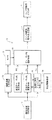
以下図面を参照して本発明の実施形態を説明する。以下に示す実施形態では、内燃機関駆動車両が自動二輪車であるとする。図1は、本発明の一実施形態を示したもので、同図において1は自動二輪車を駆動する内燃機関により回転駆動される磁石式交流発電機(以下単に交流発電機ともいう。)、2は交流発電機1の出力で充電されるバッテリ、3はバッテリ2からランプ駆動電流が与えられて点灯する車両のヘッドランプである。また5は、ダイオードとサイリスタとの混合ブリッジ回路からなっていて、交流発電機1の出力を整流してその出力電流を充電電流としてバッテリ2に供給する制御整流回路、6はバッテリ2の両端の電圧を設定値に保つように制御整流回路5を制御するバッテリ充電制御部、7はヘッドランプ3に供給される電流をオンオフするランプ駆動用スイッチ、8はランプ駆動用スイッチ7を所定のデューティ比でオンオフ制御して、ランプ駆動電流をバッテリ2の充電を妨げることがない値に保つようにPWM制御するランプ通電制御部である。
Embodiments of the present invention will be described below with reference to the drawings. In the embodiment described below, it is assumed that the internal combustion engine drive vehicle is a motorcycle. FIG. 1 shows an embodiment of the present invention. In FIG. 1, reference numeral 1 denotes a magnet type AC generator (hereinafter also simply referred to as an AC generator) that is driven to rotate by an internal combustion engine that drives a motorcycle. Is a battery charged by the output of the AC generator 1, and 3 is a vehicle headlamp that is turned on when a lamp driving current is applied from the battery 2. Reference numeral 5 denotes a mixed bridge circuit of a diode and a thyristor, which rectifies the output of the AC generator 1 and supplies the output current to the battery 2 as a charging current. A battery charge control unit that controls the control rectifier circuit 5 so as to keep the voltage at a set value, 7 is a lamp driving switch that turns on and off the current supplied to the
本実施形態では、交流発電機1と、バッテリ2とにより、ヘッドランプ3を含む各種の電装品に電力を供給する電源部が構成され、制御整流回路5と、バッテリ充電制御部6と、ランプ駆動用スイッチ7と、ランプ通電制御部8とにより、電源部を制御する電源部制御装置4が構成されている。
In the present embodiment, the AC generator 1 and the battery 2 constitute a power supply unit that supplies power to various electrical components including the headlamp 3, and includes a control rectifier circuit 5, a battery charge control unit 6, a lamp The
更に詳細に説明すると、磁石式交流発電機1は、自動二輪車の車体に搭載された図示しない内燃機関のクランク軸により回転駆動される回転子と、回転子の磁極にギャップを介して対向する磁極部を有する電機子鉄心に単相の電機子コイル100を巻装することにより構成された固定子とからなっていて、内燃機関の回転に同期して電機子コイル1aに単相の交流電圧を誘起する。磁石式交流発電機は、その出力電流に対する出力電圧の特性が垂下特性を有していて、出力電流の増大に伴って出力電圧が低下していく。従って、磁石式交流発電機と該磁石式交流発電機の出力で充電されるバッテリとにより電源部を構成して、バッテリの両端に負荷を接続する構成をとる場合に、低速回転時に、バッテリの両端に接続された負荷に大きな電流を流すと、交流発電機の出力電圧が低下して、バッテリの端子電圧を下回ってしまい、バッテリを充電することができなくなる。
More specifically, the magnetic AC generator 1 includes a rotor that is driven to rotate by a crankshaft of an internal combustion engine (not shown) mounted on a motorcycle body, and a magnetic pole that faces the magnetic pole of the rotor via a gap. And a stator constituted by winding a single-
電源部制御装置4は、ダイオードとサイリスタとの混合ブリッジ回路からなっていて、交流発電機1の出力を整流してその出力電流を充電電流としてバッテリ2に供給する制御整流回路5と、バッテリ2の両端の電圧を設定値に保つように制御整流回路5を制御するバッテリ充電制御部6と、バッテリ2とヘッドランプ3との間に設けられてヘッドランプ3に供給されるランプ駆動電流をオンオフするランプ駆動用スイッチ7と、ランプ駆動用スイッチ7を所定のデューティ比でオンオフ制御してランプ駆動電流をバッテリ2の充電を妨げることがない値に保つようにPWM制御するランプ通電制御部8とにより構成されている。
The power supply control unit 4 is composed of a mixed bridge circuit of a diode and a thyristor, rectifies the output of the AC generator 1 and supplies the output current to the battery 2 as a charging current, and the battery 2. A battery charge control unit 6 that controls the control rectifier circuit 5 so as to keep the voltage at both ends of the battery at a set value, and a lamp driving current that is provided between the battery 2 and the headlamp 3 and is supplied to the headlamp 3 is turned on / off. A
制御整流回路5は、アノードが接地回路に共通接続されたダイオードD1及びD2と、アノードがダイオードD1及びD2のカソードにそれぞれ接続され、カソードが共通接続されたサイリスタTh1及びTh2とにより構成されている。この制御整流回路においては、ダイオードD1及びD2のカソードとサイリスタTh1及びTh2のアノードとの接続点が交流入力端子5a及び5bとなっており、サイリスタTh1及びTh2のカソードの共通接続点及びダイオードD1及びD2のアノードの共通接続点(接地)がそれぞれプラス側直流出力端子5c及びマイナス側直流出力端子5dとなっている。交流入力端子5a及び5bはそれぞれ交流発電機1の一方の出力端子1a及び他方の出力端子1bに接続され、直流出力端子5c及び5dはそれぞれバッテリ2の正極端子及び負極端子に接続されている。
The control rectifier circuit 5 includes diodes D1 and D2 whose anodes are commonly connected to the ground circuit, and thyristors Th1 and Th2 whose anodes are connected to the cathodes of the diodes D1 and D2, respectively, and whose cathodes are commonly connected. . In this control rectifier circuit, the connection points between the cathodes of the diodes D1 and D2 and the anodes of the thyristors Th1 and Th2 are the
ランプ駆動用スイッチ7は、ソースがバッテリ2の正極端子に接続されたNチャンネル型のMOSFETからなっていて、そのドレインと接地間にヘッドランプ3が接続されている。
The
バッテリ充電制御部6は、バッテリ2の両端の電圧(バッテリ電圧)を検出する電圧検出回路と、電圧検出回路により検出されたバッテリ電圧が設定値未満のときにサイリスタTh1及びTh2のゲートにトリガ信号を与え、検出されたバッテリ電圧が設定値以上になったときにサイリスタTh1及びTh2へのトリガ信号の供給を停止するようにサイリスタへのトリガ信号の供給を制御するサイリスタトリガ制御部とを備えた公知の構成を有している。制御整流回路5は、バッテリ電圧が設定値未満で、バッテリ充電制御部からサイリスタTh1及びTh2にトリガ信号が与えられているときに、これらのサイリスタのうちアノードカソード間に順方向電圧が印加されている方のサイリスタがオン状態になって、交流発電機1の整流出力電流をバッテリ2に充電電流として供給する。バッテリ電圧が設定値以上になってサイリスタTh1及びTh2へのトリガ信号の供給が停止されると、サイリスタTh1及びTh2がそれぞれのアノード電流が保持電流以下になった時点でオフ状態になって、バッテリ2への充電電流の供給を停止する。バッテリ充電制御部6は、制御整流回路5にこれらの動作を行なわせることにより、バッテリ電圧を設定値に保つように制御する。バッテリ電圧の定格値が12[V]である場合、バッテリ電圧の設定値は、例えば14.5[V]に設定される。 The battery charge control unit 6 detects a voltage (battery voltage) across the battery 2 and a trigger signal to the gates of the thyristors Th1 and Th2 when the battery voltage detected by the voltage detection circuit is less than a set value. And a thyristor trigger control unit for controlling the supply of the trigger signal to the thyristor so as to stop the supply of the trigger signal to the thyristors Th1 and Th2 when the detected battery voltage becomes equal to or higher than the set value. It has a known configuration. When the battery voltage is less than the set value and the trigger signal is given to the thyristors Th1 and Th2 from the battery charge control unit, the control rectifier circuit 5 applies a forward voltage between the anode and cathode of these thyristors. The thyristor on the other side is turned on to supply the rectified output current of the AC generator 1 to the battery 2 as a charging current. When the supply of the trigger signal to the thyristors Th1 and Th2 is stopped when the battery voltage becomes equal to or higher than the set value, the thyristors Th1 and Th2 are turned off when the respective anode currents become lower than the holding current. 2 stops supplying charging current. The battery charge control unit 6 controls the battery voltage to be kept at a set value by causing the control rectifier circuit 5 to perform these operations. When the rated value of the battery voltage is 12 [V], the set value of the battery voltage is set to 14.5 [V], for example.
また本実施形態で用いているバッテリ充電制御部6は、上記の制御を行なう他、ドライバーにより車両を加速する操作が行なわれたことが検出されたときに、交流発電機1から内燃機関にかかる負荷を軽減して加速性能を向上させるために、サイリスタTh1及びTh2へのトリガ信号の供給を停止してバッテリの充電を停止する加速時充電停止制御を行なうように構成されている。加速操作が行なわれたか否かは、内燃機関の回転速度を監視して、該回転速度の上昇率が設定値を超えたか否かを見るか、又は車両に設けられているアクセルグリップ等のアクセル操作部材の変位を監視することにより検出することができる。内燃機関の回転速度は、交流発電機1の出力周波数から検出することができる。また内燃機関の点火時期の制御等を行なう際に必要とするクランク角情報を得るために、クランク軸の回転角度位置が設定された位置に達する毎にパルスを発生するパルス発生器が設けられている場合には、該パルス発生器が発生するパルスの発生間隔を検出することにより、機関の回転速度を検出することができる。 The battery charge control unit 6 used in the present embodiment performs the above-described control, and when it is detected that an operation for accelerating the vehicle is performed by the driver, the AC generator 1 applies to the internal combustion engine. In order to reduce the load and improve the acceleration performance, it is configured to perform charge stop control during acceleration in which the supply of the trigger signal to the thyristors Th1 and Th2 is stopped to stop the charging of the battery. Whether or not the acceleration operation has been performed is determined by monitoring the rotational speed of the internal combustion engine and checking whether or not the rate of increase of the rotational speed has exceeded a set value, or an accelerator such as an accelerator grip provided in the vehicle. It can be detected by monitoring the displacement of the operating member. The rotational speed of the internal combustion engine can be detected from the output frequency of the AC generator 1. In addition, in order to obtain crank angle information necessary for controlling the ignition timing of the internal combustion engine, a pulse generator is provided that generates a pulse every time the rotation angle position of the crankshaft reaches a set position. If so, the rotational speed of the engine can be detected by detecting the generation interval of the pulses generated by the pulse generator.
なお定常走行時に比較的ゆっくりと加速操作が行なわれた場合にも加速時充電停止制御を行なうようにバッテリ充電制御部6を構成すると、バッテリの充電を十分に行なうことができなくなるおそれがあるので、バッテリ充電制御部6は、設定された加速割合以上の加速割合で車両を急加速する加速操作(アクセル操作)が行なわれた場合にのみ加速時充電停止制御を行ない、比較的ゆっくりと加速操作が行なわれた際には、加速時充電停止制御を行なわないようにするのが好ましい。 If the battery charge control unit 6 is configured to perform the charge stop control during acceleration even when the acceleration operation is performed relatively slowly during steady running, the battery may not be sufficiently charged. The battery charge control unit 6 performs charge stop control during acceleration only when an acceleration operation (accelerator operation) for suddenly accelerating the vehicle at an acceleration rate higher than the set acceleration rate is performed, and the acceleration operation is performed relatively slowly. When this is done, it is preferable not to perform charge stop control during acceleration.
上記の説明から明らかなように、バッテリ充電制御部6を構成するためには、バッテリ電圧や機関の加速操作の有無の検出を行なう検出手段や、バッテリ電圧が設定値を超えたか否かを判定する判定処理、及び設定された加速割合以上で加速操作が行なわれたか否かを判定する判定処理等の各種の判定処理を行なう手段や、判定結果に基づいてサイリスタTh1,Th2に与えるトリガ信号を発生させたり消滅させたりする処理を行なう手段等の各種の機能実現手段を構成する必要がある。これらの手段は、アナログ回路により構成してもよく、マイクロプロセッサに所定のタスクを実行させることにより構成してもよい。内燃機関の点火装置や燃料噴射量などを制御するためにECU(電子制御ユニット)が設けられる場合には、当該ECU内に設けられるマイクロプロセッサに所定のプログラムを実行させることによりバッテリ充電制御部を構成するために必要な手段を実現することができる。なお上記のような制御動作を行なうバッテリ充電制御部自体は、既に当業者に広く知られているので、その回路構成や、マイクロプロセッサに実行させるタスク処理のアルゴリズム等についての詳細な説明は省略する。 As is apparent from the above description, in order to configure the battery charge control unit 6, it is determined whether or not the battery voltage or the acceleration operation of the engine is detected, or whether or not the battery voltage exceeds a set value. Means for performing various determination processes such as a determination process for determining whether or not an acceleration operation has been performed at a set acceleration rate or higher, and a trigger signal to be applied to the thyristors Th1 and Th2 based on the determination result It is necessary to configure various function realization means such as means for performing processing to be generated or extinguished. These means may be constituted by an analog circuit or may be constituted by causing a microprocessor to execute a predetermined task. When an ECU (electronic control unit) is provided to control an ignition device of an internal combustion engine, a fuel injection amount, etc., a battery charge control unit is controlled by causing a microprocessor provided in the ECU to execute a predetermined program. Means necessary to configure can be realized. Since the battery charge control unit itself that performs the control operation as described above is already widely known to those skilled in the art, a detailed description of its circuit configuration, algorithm for task processing executed by the microprocessor, and the like is omitted. .
本実施形態では、バッテリに供給する充電電流をオンオフするために制御整流回路5に設けるスイッチ手段としてサイリスタを用いているが、MOSFETやバイポーラトランジスタなどの他の半導体スイッチ素子を用いて制御整流回路5を構成してもよい。また交流発電機1として磁石発電機が用いられる場合には、制御整流回路5に替えて、発電機1の出力を整流する整流回路と、バッテリ電圧が設定値を超えたときに該整流回路の出力を半導体スイッチを通して短絡する出力短絡回路とを備えた周知の短絡式のレギュレータを用いることもできる。 In this embodiment, a thyristor is used as switch means provided in the control rectifier circuit 5 to turn on and off the charging current supplied to the battery. However, the control rectifier circuit 5 using other semiconductor switch elements such as MOSFETs and bipolar transistors. May be configured. When a magnet generator is used as the AC generator 1, a rectifier circuit that rectifies the output of the generator 1 instead of the control rectifier circuit 5, and a rectifier circuit when the battery voltage exceeds a set value, A well-known short-circuit regulator having an output short circuit for short-circuiting the output through the semiconductor switch can also be used.
ランプ通電制御部8は、バッテリ2からランプ駆動用スイッチ7を通してヘッドランプ3に流れるランプ駆動電流IL の平均値を所定の値に保つように、ランプ駆動用スイッチ7をオンオフ制御する部分である。ランプ通電制御部8は、ランプ駆動電流を、磁石式交流発電機1からバッテリ2の端子電圧以上の出力電圧を発生させることができる範囲の値に保つべく設定されたランプ駆動用スイッチ7のオンオフのデューティ比Dnを正規デューティ比として、この正規デューティ比でランプ駆動用スイッチをオンオフ制御することを基本としてランプ駆動電流をPWM制御する。正規デューティ比でランプ駆動用スイッチをPWM制御している限り、磁石式交流発電機の出力電流が、該発電機の出力電圧をバッテリの端子電圧以下に低下させる大きさになることはないため、バッテリの充電は支障なく行われる。
The lamp
本実施形態では、ランプ通電制御部8を、内燃機関の減速時にその回転速度がアイドリング回転速度に近づいていく過程で機関の回転速度がアイドリング回転速度よりも高く設定された設定回転速度まで低下した時に正規デューティ比でのランプ駆動用スイッチのオンオフ制御を中断して、内燃機関のアイドリング時の正規デューティ比Dniよりも大きい値に設定された設定デューティ比Dsでランプ駆動用スイッチ7をオンオフ制御する機関減速時ランプ通電制御を、制限された時間の間だけ行なうように構成する。設定デューティ比Dsは、内燃機関のアイドリング時の正規デューティ比Dnよりも十分大きい値に設定される。ランプ通電制御部8は、上記機関減速時ランプ通電制御を行うために、内燃機関の回転速度情報を必要とする。本実施形態では、内燃機関の回転速度情報をランプ通電制御部8に与えるため、交流発電機1の出力電圧の情報がランプ通電制御部8に入力されている。ランプ通電制御部8は、交流発電機1の出力周波数から内燃機関の回転速度情報を取得する。
In the present embodiment, when the internal combustion engine is decelerated, the lamp
本明細書では、ランプ駆動用スイッチのオンオフのデューティ比Dを、スイッチ7をオン状態にする期間が、スイッチ7のオンオフサイクルの1周期に対して占める割合を意味する語として用いる。即ち、図4に示すように、スイッチ7のオン期間をTon、オフ期間をToff とし、オンオフサイクルの1周期をT(=Ton+Toff )としたときに、D=(Ton/T)×100[%]で与えられる値をランプ駆動用スイッチのオンオフのデューティ比Dとする。
In this specification, the on / off duty ratio D of the lamp driving switch is used as a term meaning the ratio of the period during which the
図2を参照すると、本実施形態に係わる電源部制御装置のランプ通電制御部8の基本的な動作を示したもので、同図において、Igは交流発電機1から制御整流回路5を通して出力される出力電流を示し、IL はバッテリ2からランプ駆動用スイッチ7を通してヘッドランプ3に流れるランプ駆動電流を模式的に示している。またDn はランプ駆動用スイッチ7のオンオフの正規デューティ比の一例であり、Nは交流発電機1を駆動する内燃機関の回転速度[r/min ]の一例である。正規デューティ比Dn は、内燃機関の各回転速度Nにおいて、バッテリ2からランプ駆動用スイッチ7を通してヘッドランプ3に流れるランプ駆動電流ILを、バッテリ2の充電を妨げることがない(充電電流を支障なく流すことができる)値に保つように定められる。
Referring to FIG. 2, the basic operation of the lamp
図示の例では、正規デューティ比Dnを、回転速度Nの上昇に伴って段階的に増大させるようにしており、アイドリング時の正規デューティ比Dnを50[%]、機関の回転速度Nが2000[r/min ]のときの正規デューティ比Dnを90[%]に設定している。図2において、発電機の出力電流Ig とランプ駆動電流IL との差の電流Icがバッテリ2に流れる充電電流となる。本実施形態では、機関の始動が完了する回転速度を500[r/min ]、アイドリング回転速度をNi (>800[r/min ])としている。 In the illustrated example, the normal duty ratio Dn is increased stepwise as the rotational speed N increases, the normal duty ratio Dn at idling is 50 [%], and the engine rotational speed N is 2000 [%]. The normal duty ratio Dn at the time of [r / min] is set to 90 [%]. In FIG. 2, the current Ic, which is the difference between the output current Ig of the generator and the lamp driving current IL, becomes the charging current flowing through the battery 2. In the present embodiment, the rotational speed at which the engine start is completed is 500 [r / min], and the idling rotational speed is Ni (> 800 [r / min]).
ランプ通電制御部8は、機関の回転速度Nに対して正規デューティ比Dn を演算して、演算した正規デューティ比Dn でハイレベルとローレベルとの間を変化する矩形波状の駆動信号Vd をランプ駆動用スイッチ7を構成するMOSFETのゲートに供給する。これによりランプ駆動用スイッチ7が正規デューティ比Dn でオンオフして、バッテリ2からヘッドランプ3に供給されるランプ駆動電流IL をPWM制御する。この制御により、磁石式交流発電機1の出力電流が過大になって、その出力電圧がバッテリ2の端子電圧以下に低下するのを防き、バッテリの充電が行われなくなる状態が生じるのを防いでいる。
The lamp
本実施形態で用いているランプ通電制御部8は、例えば車両を減速又は停止させる際等に、機関を減速していく過程で、内燃機関の回転速度がアイドリング回転速度よりも所定回転速度だけ高く設定された設定回転速度まで低下したときにタイマに設定時間の計測を開始させ、タイマが設定時間の計測を行なっている間、ランプ駆動用スイッチのオンオフのデューティ比を設定デューティ比に固定するように構成される。
In the process of decelerating the engine, for example, when the vehicle is decelerated or stopped, the lamp
このように構成すると、機関減速時ランプ通電制御を行なう時間の設定を容易にすることができる。またタイマに計測させる時間を変更することにより、機関減速時ランプ通電制御を行なう時間を自在に調整することができる。 If comprised in this way, the setting of the time which performs lamp energization control at the time of engine deceleration can be made easy. Further, by changing the time to be measured by the timer, the time for performing the lamp energization control during engine deceleration can be freely adjusted.
上記設定デューティ比は、設定回転速度における正規デューティ比に等しく設定するのが好ましい。このように設定デューティ比を設定しておくと、機関減速時ランプ通電制御を開始する際にヘッドランプがちらつくのを防ぐことができる。 The set duty ratio is preferably set equal to the normal duty ratio at the set rotational speed. If the set duty ratio is set in this way, it is possible to prevent the headlamp from flickering when starting the lamp energization control during engine deceleration.
ランプ通電制御部8はまた、設定時間の計測が完了したときに、デューティ比をアイドリング時における正規デューティ比に向けて徐々に変化させるように構成されていることが好ましい。
The
このように構成しておくと、機関減速時ランプ通電制御を終了する際にヘッドランプの光量が急激に減少するのを防ぐことができるため、ドライバーに違和感を抱せることなく、ヘッドランプを徐々に減光させることができる。 By configuring in this way, it is possible to prevent the light quantity of the headlamp from abruptly decreasing when the lamp energization control at the time of engine deceleration is finished, so that the headlamp is gradually turned on without causing the driver to feel uncomfortable. Can be dimmed.
本実施形態で用いているランプ通電制御部8は、ドライバーが車両を発進させる操作を行なった際に、図3に示したように、機関の回転速度Nが2000[r/min ]に達したところで、ランプ駆動用スイッチ7のオンオフのデューティ比Dを50[%]から90[%]まで上昇させ、回転速度Nが3000[r/min ]に達したときにデューティ比Dを95[%]に、また回転速度Nが4000[r/min ]に達したときにデューティ比Dを100[%]に切り換える。ランプ通電制御部8は又、例えばドライバーが車両を停止させるために制動をかけたときに、機関が減速し、その回転速度がアイドリング回転速度に近づいていく過程で、回転速度Nがアイドリング回転速度よりも高く設定された設定速度Nsまで低下したときにタイマに設定時間Tcを計測する動作を行なわせ、タイマがこの計測動作を行なっている間ランプ駆動用スイッチ7のオンオフのデューティ比Dをアイドリング時の正規デューティ比(50[%])よりも高く設定された設定デューティ比Ds(図示の例では90%)に固定する機関減速時ランプ通電制御を行なう。本実施形態では、設定デューティ比Dsを、設定回転速度Nsにおける正規デューティ比に等しく設定している。
In the lamp
ランプ通電制御部8に上記のような制御を行なわせると、例えば車両を停止または減速する過程で、機関の回転速度が低下し、ランプ駆動用スイッチのオンオフのデューティ比がアイドリング時の正規デューティ比に切り替わる前に、正規デューティ比でのランプ駆動用スイッチのオンオフ制御を中断して、内燃機関のアイドリング時の正規デューティ比よりも大きい値に設定された設定デューティ比Dsでランプ駆動用スイッチをオンオフ制御することができる。従って、機関の減速時にその回転速度がアイドリング回転速度に近づいていく過程でヘッドランプの光量が急減する現象が生じるのを防いで、ランプのちらつきを防ぎ、所定時間の間ヘッドランプの光量を高い状態に保つことができる。また機関減速時ランプ通電制御は、制限された時間Tcの間だけ行なうので、バッテリが過放電状態になるのを防止できる。
When the lamp
上記のような機能を有するランプ通電制御部8は、車両に搭載されるECUに設けられているマイクロプロセッサに所定のプログラムを実行させることにより実現することができる。図5は、上記のランプ通電制御部8をマイクロプロセッサにより実現する場合にソフトウェア上で構成される機能ブロックの一例を示した機能ブロック図である。図5において、11は、内燃機関の回転速度を検出する回転速度検出手段で、本実施形態では、この回転速度検出手段が、磁石式交流発電機1の出力周波数から機関の回転速度を検出するように構成されている。なお回転速度検出手段11は、内燃機関の点火時期などを制御するために別途検出されている機関の回転速度情報を取得する手段により構成することもできる。
The lamp
12は回転速度検出手段11により検出された内燃機関の回転速度の変化から、機関が減速する過程でその回転速度がアイドリング回転速度よりも高い値に設定された設定回転速度まで低下したか否かを判定する機関減速判定手段、13は、機関減速判定手段12により、機関が減速する過程でその回転速度が設定回転速度まで低下したと判定されたときに設定時間Tcの計測を開始するタイマである。また14は、回転速度検出手段11により検出された機関の回転速度Nに対して、ランプ駆動電流ILを、バッテリ2の充電を妨げることがない(充電電流を支障なく流すことができる)値に保つことができる正規デューティ比Dnを演算する正規デューティ比演算手段である。正規デューティ比Dnの演算は、機関の回転速度Nと正規デューティ比Dnとの間の関係を与えるマップ(テーブル)を回転速度Nに対して検索することにより行なうことができる。
12 shows whether or not the rotational speed of the internal combustion engine detected by the rotational speed detection means 11 has decreased to a set rotational speed set to a value higher than the idling rotational speed in the course of deceleration of the engine. The engine deceleration determination means 13 for determining the engine speed is a timer that starts measuring the set time Tc when the engine deceleration determination means 12 determines that the rotational speed has decreased to the set rotational speed in the course of engine deceleration. is there. Further, 14 is a value that does not hinder the charging of the battery 2 (can flow the charging current without any trouble) with respect to the engine speed N detected by the
15は設定デューティ比Dsを決定する設定デューティ比決定手段で、この手段は、予め定めた設定デューティ比Dsを記憶させる記憶手段により構成することができる。また16はデューティ比選択手段で、この選択手段は、機関減速判定手段12により機関が減速中でないと判定されているとき、及び機関が減速中であるがその回転速度が設定回転速度までは低下していないと判定されていて、タイマ13が計時動作を行なっていないときに、正規デューティ比演算手段14により演算された正規デューティ比Dnをランプ駆動用スイッチ7のオンオフのデューティ比Dとして選択して出力し、機関減速判定手段12により機関が減速中に設定回転速度まで低下したと判定されて、タイマ13が計時動作を行なっているときに設定デューティ比Dsをランプ駆動用スイッチ7のオンオフのデューティ比Dとして選択して出力するように構成される。
デューティ比選択手段16は、選択したデューティ比Dをスイッチ駆動信号出力回路17に与える。スイッチ駆動信号出力回路17は、デューティ比選択回路16から与えられる信号をランプ駆動用スイッチ7を駆動するのに適した駆動信号(図4に示したような矩形波状の信号)として、該駆動信号をランプ駆動用スイッチ7の制御端子(図示の例ではMOSFETのゲート)に与える。図5に示した例では、回転速度検出手段11と、機関減速判定手段12と、タイマ13と、正規デューティ比演算手段14と、設定デューティ比決定手段15と、デューティ比選択手段16と、スイッチ駆動信号出力回路17とによりランプ通電制御部8が構成される。
The duty ratio selection means 16 gives the selected duty ratio D to the switch drive
図5に示したランプ通電制御部を構成するためにマイクロプロセッサに実行させるタスク処理のアルゴリズムの一例を図6に示した。図6に示した処理は、一定の時間間隔で発生するタスク処理タイミングが到来する毎に実行される。このタスク処理が開始されると、先ずステップS101で、内燃機関の現在の回転速度Nに対して正規デューティ比Dnが演算される。次いでステップS102で回転速度Nが、前回のタスク処理時よりも低下しているか否かを判定し、その結果低下していないと判定されたときにはステップS103に進んでデューティ比DをステップS101で演算した正規デューティ比Dnとしてこの処理を終了する。 FIG. 6 shows an example of a task processing algorithm executed by the microprocessor to configure the lamp energization control unit shown in FIG. The processing shown in FIG. 6 is executed every time task processing timing that occurs at regular time intervals arrives. When this task process is started, first, in step S101, a normal duty ratio Dn is calculated with respect to the current rotational speed N of the internal combustion engine. Next, in step S102, it is determined whether or not the rotational speed N is lower than that in the previous task processing. If it is determined that the rotational speed N has not decreased as a result, the process proceeds to step S103 and the duty ratio D is calculated in step S101. This processing is terminated as the normal duty ratio Dn.
ステップS102で回転速度が前回のタスク処理時よりも低下していると判定されたときには、ステップS104に進んで、現在の回転速度Nが設定回転速度Nsよりも低いか否かを判定する。その結果、回転速度Nが設定回転速度Ns以上であると判定されたときには、ステップS105でタイマの計測値Txを0にクリアしてステップS103に進み、デューティ比DをステップS101で演算した正規デューティ比Dnとしてこの処理を終了する。ステップS104で機関の回転速度Nが設定回転速度Nsよりも低いと判定されたときにはステップS106に進んでタイマの計測値Txを1だけインクリメントし、次いでステップS107でタイマの計測値Txが設定時間Tcに達しているか否かを判定する。その結果、タイマの計測値Txが設定時間Tcに達していないと判定されたとき(タイマが設定時間の計測を完了していないとき)には、ステップS108に進んで、デューティ比Dを設定デューティ比Dsとしてこの処理を終了する。ステップS107でタイマの計測値Txが設定値Tcに達している(設定時間の計測が完了している)と判定されたときには、ステップS109に進んでデューティ比DをステップS101で演算されているアイドリング時の正規デューティ比Dniとしてこの処理を終了する。 When it is determined in step S102 that the rotation speed is lower than that in the previous task processing, the process proceeds to step S104, and it is determined whether or not the current rotation speed N is lower than the set rotation speed Ns. As a result, when it is determined that the rotation speed N is equal to or higher than the set rotation speed Ns, the timer measurement value Tx is cleared to 0 in step S105, the process proceeds to step S103, and the normal duty calculated in step S101 is the duty ratio D. This processing is terminated as the ratio Dn. When it is determined in step S104 that the engine rotational speed N is lower than the set rotational speed Ns, the routine proceeds to step S106, where the timer measured value Tx is incremented by 1, and then in step S107 the timer measured value Tx is set to the set time Tc. It is determined whether or not. As a result, when it is determined that the measured value Tx of the timer has not reached the set time Tc (when the timer has not completed measuring the set time), the process proceeds to step S108, and the duty ratio D is set to the set duty. This processing is ended as the ratio Ds. If it is determined in step S107 that the measured value Tx of the timer has reached the set value Tc (measurement of the set time has been completed), the process proceeds to step S109, and the idling ratio D is calculated in step S101. This processing is terminated as the normal duty ratio Dni of the hour.
図6に示されたアルゴリズムによる場合、ステップS101により正規デューティ比演算手段14が構成され、ステップS102及びS104により、機関減速判定手段12が構成される。またステップS103,S107,S108及びS109により、デューティ比選択手段16が構成される。更にステップS105とS106とにより、機関の回転速度が設定回転速度Nsまで低下したときにタイマ13に設定時間をセットしてその計測を開始させ、タイマ13が設定時間を計測する計測動作を行なっている期間に回転速度Nが設定回転速度Ns以上になったときにはタイマ13をクリアするように、タイマ13を制御するタイマ制御手段(図5には図示せず。)が構成されている。
In the case of the algorithm shown in FIG. 6, the normal duty ratio calculation means 14 is configured by step S101, and the engine deceleration determination means 12 is configured by steps S102 and S104. Further, the duty ratio selection means 16 is constituted by steps S103, S107, S108 and S109. Further, in steps S105 and S106, when the engine speed decreases to the set speed Ns, the
バッテリを搭載した内燃機関駆動車両においては、車両を加速する際に、バッテリの充電が行なわれていると、交流発電機から機関にかかる負荷が重くなるため、加速性能が低下するのを避けられない。このような問題を解決するため、車両を加速する操作が行なわれたことが検出されたときにバッテリの充電を停止する加速時充電停止制御を行なうようにバッテリ充電制御部を構成することが行なわれている。加速時充電停止制御が行なわれているときには、バッテリの電圧が低下するため、ランプ駆動電流のPWM制御のデューティ比が一定であると、加速時充電停止制御が開始される際にヘッドランプの駆動電流が減少してちらつきが生じ、ドライバに違和感を抱かせることがある。 In an internal combustion engine-driven vehicle equipped with a battery, if the battery is charged when accelerating the vehicle, the load applied to the engine from the AC generator becomes heavy, so it is possible to avoid a decrease in acceleration performance. Absent. In order to solve such a problem, the battery charge control unit is configured to perform acceleration charge stop control for stopping charging of the battery when it is detected that an operation for accelerating the vehicle is performed. It is. When the acceleration charge stop control is performed, the battery voltage decreases. Therefore, if the duty ratio of the PWM control of the lamp drive current is constant, the head lamp drive is started when the acceleration charge stop control is started. The current decreases and flickering may cause the driver to feel uncomfortable.
そこで、バッテリ充電制御部が、車両を加速する操作が行なわれたことが検出されたときにバッテリの充電を停止する加速時充電停止制御を行なうように構成されている場合には、ランプ通電制御部を、加速時充電停止制御が行なわれているときに、デューティ比を、加速時充電停止制御が開始される直前の正規デューティ比以上の値に設定された加速制御時デューティ比まで増大させる加速時デューティ制御を行なうように構成するのが好ましい。 Therefore, when the battery charge control unit is configured to perform acceleration charge stop control for stopping charging of the battery when it is detected that an operation for accelerating the vehicle is performed, lamp energization control is performed. Acceleration for increasing the duty ratio to a duty ratio during acceleration control set to a value equal to or greater than the normal duty ratio immediately before the acceleration charge stop control is started when the acceleration charge stop control is performed It is preferable that the duty control is performed.
このように構成しておくと、加速時充電停止制御が行なわれてバッテリの電圧が低下したときにヘッドランプに流れる電流が減少するのを防ぐことができるため、ヘッドランプがちらつくのを防ぐことができる。 By configuring in this way, it is possible to prevent the current flowing in the headlamp from decreasing when the battery charge voltage is lowered due to the charge stop control during acceleration, thus preventing the headlamp from flickering. Can do.
ランプ通電制御部は、加速制御時の回転速度と充電停止制御時デューティ比との間の関係を与えるマップを用いて、このマップを回転速度に対して検索することにより上記加速制御時デューティ比を決定するように構成してもよく、加速時充電停止制御が開始される直前のデューティ比に一定値を加算することにより加速制御時デューティ比を決定するように構成してもよい。 The lamp energization control unit uses the map that gives the relationship between the rotation speed during acceleration control and the duty ratio during charge stop control, and searches the map for the rotation speed to obtain the duty ratio during acceleration control. The acceleration control duty ratio may be determined by adding a constant value to the duty ratio immediately before the acceleration charge stop control is started.
バッテリ充電制御部が、車両を加速する操作が行なわれたことが検出されたときにバッテリの充電を停止する加速時充電停止制御を行なうように構成されている場合、ランプ通電制御部は、加速時充電停止制御が行なわれているときにバッテリの電圧を監視して、ヘッドランプの光量を加速時充電停止制御が開始される直前の光量に保つべく、バッテリ電圧に応じてデューティ比を決定するように構成されてもよい。 When the battery charge control unit is configured to perform acceleration charge stop control for stopping charging of the battery when it is detected that an operation for accelerating the vehicle is performed, the lamp energization control unit is accelerated. The battery voltage is monitored when the on-time charge stop control is being performed, and the duty ratio is determined according to the battery voltage in order to keep the light quantity of the headlamp at the light quantity just before the acceleration charge stop control is started. It may be configured as follows.
図7は本発明の他の実施形態においてランプ通電制御部8をマイクロプロセッサを用いて構成する場合に、ソフトウェア上で構成される機能ブロックの一例を示した機能ブロック図である。本実施形態では、図1に示されたバッテリ充電制御部6が、車両を加速する操作が行なわれたことが検出されたときにバッテリの充電を停止する加速時充電停止制御を行なうように構成されている。加速操作が行なわれたときにバッテリの充電を停止させる加速時充電停止制御が行なわれると、バッテリ電圧が低下するため、ヘッドランプ3の光量が減少し、ドライバーに不快感を与えるおそれがある。本実施形態は、バッテリ充電制御部6が加速時充電停止制御を行なっているときにヘッドランプが減光するのを防ぐようにしたものである。本実施形態においては、加速時充電停止制御が行なわれているときに、ランプ通電制御部8が、ランプ駆動用スイッチ7のオンオフのデューティ比を、加速時充電停止制御が開始される直前の正規デューティ比以上の値に設定された加速制御時デューティ比まで増大させる加速時デューティ制御を行なうように構成されている。
FIG. 7 is a functional block diagram showing an example of functional blocks configured on software when the lamp
図7に示された実施形態では、図5に示された構成に加えて、加速制御情報を与える手段18と、加速制御時デューティ比決定手段19とが設けられている。加速情報は、バッテリ充電制御部6が加速時充電停止制御を行なっていることを示す情報であり、バッテリ充電制御部6から取得することができる。 In the embodiment shown in FIG. 7, in addition to the configuration shown in FIG. 5, means 18 for giving acceleration control information and duty ratio determining means 19 for acceleration control are provided. The acceleration information is information indicating that the battery charge control unit 6 is performing charge stop control during acceleration, and can be acquired from the battery charge control unit 6.
加速制御時デューティ比決定手段19は、加速時充電停止制御が行なわれているときに、該加速時充電停止制御が開始される直前の正規デューティ比以上の値を有する加速制御時デューティ比Daを決定する手段である。例えば、図3において、機関の回転速度Nが3500[r/min ]のときに加速時充電停止制御が行なわれた場合、加速制御時デューティ比決定手段19は、加速制御時デューティ比Daを3500[r/min ]のときの正規デューティ比(例えば95%)よりも大きいデューティ比(例えば100%)に設定する。加速時充電停止制御が開始される直前の正規デューティ比が100%である場合には、加速制御時デューティ比Daを100%とする。
The acceleration control duty
加速制御時デューティ比決定手段19は、加速制御時の内燃機関の回転速度と前記加速制御時デューティ比との間の関係を与えるマップを用いて、内燃機関の回転速度Nに対してマップを検索することにより加速制御時デューティ比Daを決定するように構成されている。 The acceleration control duty ratio determining means 19 uses a map that gives the relationship between the rotational speed of the internal combustion engine during acceleration control and the acceleration control duty ratio to search the map for the rotational speed N of the internal combustion engine. Thus, the acceleration control duty ratio Da is determined.
本実施形態のように、加速時充電停止制御が行なわれているときにランプ駆動用スイッチのオンオフのデューティ比を大きくする制御を行なうようにすると、充電が停止されたことによりバッテリ電圧が低下しても、ヘッドランプに供給する電力が低下しないようにすることができるため、加速時充電停止制御が行なわれたときにヘッドランプが減光するのを防ぐことができる。図7に示されたランプ通電制御部のその他の構成は、図5に示したものと同様である。 As in this embodiment, when the control for increasing the on / off duty ratio of the lamp driving switch is performed while the charge stop control during acceleration is performed, the battery voltage decreases due to the stop of the charge. However, since it is possible to prevent the power supplied to the headlamp from being reduced, it is possible to prevent the headlamp from dimming when the charge stop control during acceleration is performed. The other configuration of the lamp energization control unit shown in FIG. 7 is the same as that shown in FIG.
図7に示したランプ通電制御部を構成するためにマイクロプロセッサに実行させるタスク処理のアルゴリズムの一例を図8に示した。図8において、ステップS203ないしS210はそれぞれ図6のステップS102ないしS109と同じである。図8に示した処理も、一定の時間間隔で発生するタスク処理タイミングが到来する毎に実行される。このタスク処理が開始されると、先ずステップS201で、内燃機関の現在の回転速度Nに対して正規デューティ比Dnが演算される。次いでステップS202でバッテリ充電制御部が加速時充電停止制御を行なっているか否かを判定する。その結果、加速時充電停止制御が行なわれていないと判定されたときには、ステップS203に進む。ステップS202で加速時充電停止制御が行なわれていると判定されたときには、ステップS211に進んで回転速度Nに対して加速制御時デューティ比Daを演算し、加速時充電停止制御が開始される直前の正規デューティ比以上の値を有する加速制御時デューティ比Daを演算し、ステップS212で、ランプ駆動用スイッチのオンオフのデューティ比を演算された加速制御時デューティ比Daとしてこの処理を終了する。その他は図6に示した実施形態と同じである。 FIG. 8 shows an example of a task processing algorithm executed by the microprocessor to configure the lamp energization control unit shown in FIG. In FIG. 8, steps S203 to S210 are the same as steps S102 to S109 of FIG. The processing shown in FIG. 8 is also executed every time task processing timing that occurs at regular time intervals arrives. When this task process is started, first, in step S201, the normal duty ratio Dn is calculated with respect to the current rotational speed N of the internal combustion engine. Next, in step S202, it is determined whether or not the battery charge control unit is performing charge stop control during acceleration. As a result, when it is determined that the acceleration charge stop control is not performed, the process proceeds to step S203. If it is determined in step S202 that the acceleration charge stop control is being performed, the process proceeds to step S211 to calculate the acceleration control duty ratio Da for the rotational speed N, and immediately before the acceleration charge stop control is started. The acceleration control duty ratio Da having a value equal to or greater than the normal duty ratio is calculated, and in step S212, the on / off duty ratio of the lamp driving switch is set as the calculated acceleration control duty ratio Da. Others are the same as the embodiment shown in FIG.
図8に示されたアルゴリズムによる場合、ステップS201により正規デューティ比演算手段14が構成され、ステップS203及びS205により、機関減速判定手段12が構成される。またステップS204,S209,S210及びS212により、デューティ比選択手段16が構成される。更にステップS206とS207とにより、機関の回転速度が設定回転速度Nsまで低下したときにタイマ13に設定時間をセットしてその計測を開始させ、タイマ13が設定時間を計測する計測動作を行なっている期間に回転速度Nが設定回転速度Ns以上になったときにはタイマ13をクリアするように、タイマ13を制御するタイマ制御手段(図7には図示せず。)が構成される。またステップS211により、加速制御時デューティ比決定手段19が構成される。
In the case of the algorithm shown in FIG. 8, the normal duty ratio calculating means 14 is configured by step S201, and the engine
図9は本発明の更に他の実施形態において、ランプ通電制御部8をマイクロプロセッサを用いて構成する場合にソフトウェア上で構成される機能ブロックの一例を示した機能ブロック図である。本実施形態では、ランプ通電制御部8が、加速時充電停止制御が行なわれているときにバッテリの電圧を監視して、ヘッドランプの光量を加速時充電停止制御が開始される直前の光量に保つべく、バッテリ電圧に応じて加速制御時デューティ比を決定するように構成されている。そのため、図9に示されたバッテリ通電制御部8においては、バッテリ電圧を検出するバッテリ電圧検出手段20が設けられ、加速制御時充電停止制御が行なわれているときに、加速制御時デューティ比決定手段19が、バッテリ電圧検出手段20により検出されたバッテリ電圧に対してマップを検索することにより、加速制御時デューティ比を決定するように構成されている。その他の点は図7に示した例と同様である。
FIG. 9 is a functional block diagram showing an example of functional blocks configured on software when the lamp
図9に示したランプ通電制御部を構成するためにマイクロプロセッサに実行させるタスク処理のアルゴリズムの一例を図10に示した。図10において、ステップS301は図6のステップS101と同じであり、ステップS303ないしS310はそれぞれ図6のステップS101ないしS109と同じである。図10に示した処理も、一定の時間間隔で発生するタスク処理タイミングが到来する毎に実行される。このタスク処理が開始されると、先ずステップS301で、内燃機関の現在の回転速度Nに対して正規デューティ比Dnが演算される。次いでステップS302でバッテリ充電制御部が加速時充電停止制御を行なっているか否かを判定する。その結果、加速時充電停止制御が行なわれていないと判定されたときには、ステップS303に進む。ステップS302で加速時充電停止制御が行なわれていると判定されたときには、ステップS311に進んでバッテリ電圧に対してヘッドランプの光量を一定に保持するために必要な値を有する加速制御時デューティ比Daを演算し、ステップS312で、ランプ駆動用スイッチのオンオフのデューティ比を演算された加速制御時デューティ比Daとしてこの処理を終了する。その他は図6に示した実施形態と同じである。 FIG. 10 shows an example of a task processing algorithm executed by the microprocessor to configure the lamp energization control unit shown in FIG. 10, step S301 is the same as step S101 in FIG. 6, and steps S303 to S310 are the same as steps S101 to S109 in FIG. 6, respectively. The processing shown in FIG. 10 is also executed every time task processing timing that occurs at regular time intervals arrives. When this task processing is started, first, in step S301, the normal duty ratio Dn is calculated with respect to the current rotational speed N of the internal combustion engine. Next, in step S302, it is determined whether or not the battery charge control unit is performing charge stop control during acceleration. As a result, when it is determined that the acceleration charge stop control is not performed, the process proceeds to step S303. When it is determined in step S302 that the acceleration charge stop control is being performed, the process proceeds to step S311 and the acceleration control duty ratio having a value necessary for keeping the light quantity of the headlamp constant with respect to the battery voltage is obtained. Da is calculated, and in step S312, the on / off duty ratio of the lamp driving switch is set as the calculated acceleration control duty ratio Da, and the process ends. Others are the same as the embodiment shown in FIG.
図10に示されたアルゴリズムによる場合、ステップS301により正規デューティ比演算手段14が構成され、ステップS303及びS305により、機関減速判定手段12が構成される。またステップS304,S309,S310,及びS312により、デューティ比選択手段16が構成される。更にステップS306とS307とにより、機関の回転速度が設定回転速度Nsまで低下したときにタイマ13に設定時間をセットしてその計測を開始させ、タイマ13が設定時間を計測する計測動作を行なっている期間に回転速度Nが設定回転速度Ns以上になったときにはタイマ13をクリアするように、タイマ13を制御するタイマ制御手段が構成される。またステップS311により、加速制御時デューティ比決定手段19が構成される。
In the case of the algorithm shown in FIG. 10, the normal duty ratio calculation means 14 is configured by step S301, and the engine deceleration determination means 12 is configured by steps S303 and S305. Further, the duty ratio selection means 16 is configured by steps S304, S309, S310, and S312. Further, in steps S306 and S307, when the engine speed decreases to the set speed Ns, the
図11は本発明の更に他の実施形態においてランプ通電制御部8をマイクロプロセッサを用いて構成する場合に、ソフトウェア上で構成される機能ブロックの一例を示した機能ブロック図である。本実施形態では、回転速度検出手段11により検出された回転速度から、機関の回転速度が設定値以上であるか否かを判定する回転速度判定手段21が設けられている。またバッテリ電圧を検出するバッテリ電圧検出手段20が設けられ、正規デューティ比演算手段14は、内燃機関の回転速度が設定値未満のときに内燃機関の回転速度に対して正規デューティ比Dnを演算し、内燃機関の回転速度が設定値以上のときにはバッテリ電圧に対して正規デューティ比Dnを演算するように構成されている。その他の点は、図5に示された実施形態のランプ通電制御部8と同様に構成されている。
FIG. 11 is a functional block diagram showing an example of functional blocks configured on software when the lamp
図11に示したランプ通電制御部を構成するためにマイクロプロセッサに実行させるタスク処理のアルゴリズムの一例を図12に示した。図12において、ステップS402及びステップS404ないしS411はそれぞれ、図6のステップS101ないしS109と同一である。図12に示した処理も、一定の時間間隔で発生するタスク処理タイミングが到来する毎に実行される。このタスク処理が開始されると、先ずステップS401で、機関の回転速度Nが設定回転速度N1以上であるか否かを判定する。その結果、回転速度Nが設定値N1未満であると判定されたときには、ステップS402で現在の回転速度Nに対してマップを検索して正規デューティ比Dnを演算する。またステップS401で回転速度Nが設定値N1以上であると判定されたときにはステップS403でバッテリ電圧に対してマップを検索して正規デューティ比Dnを演算する。ステップS402または403を実行した後、ステップ404に進む。その他は図6に示した実施形態と同じである。 FIG. 12 shows an example of a task processing algorithm executed by the microprocessor in order to configure the lamp energization control unit shown in FIG. In FIG. 12, step S402 and steps S404 to S411 are the same as steps S101 to S109 of FIG. The processing shown in FIG. 12 is also executed every time task processing timing that occurs at regular time intervals arrives. When this task process is started, first, in step S401, it is determined whether or not the engine speed N is equal to or higher than the set speed N1. As a result, when it is determined that the rotational speed N is less than the set value N1, a normal duty ratio Dn is calculated by searching a map for the current rotational speed N in step S402. If it is determined in step S401 that the rotational speed N is greater than or equal to the set value N1, a map is searched for the battery voltage in step S403 to calculate the normal duty ratio Dn. After executing step S402 or 403, the process proceeds to step 404. Others are the same as the embodiment shown in FIG.
図12に示されたアルゴリズムによる場合、ステップS401により回転速度判定手段21が構成され、ステップS402及びS403により、正規デューティ比演算手段14が構成される。またステップS404及びS406により、機関減速判定手段12が構成され、ステップS405,S409,S410及びS411により、デューティ比選択手段16が構成される。更にステップS406とS407とにより、機関の回転速度が設定回転速度Nsまで低下したときにタイマ13に設定時間をセットしてその計測を開始させ、タイマ13が設定時間を計測する計測動作を行なっている期間に回転速度Nが設定回転速度Ns以上になったときにはタイマ13をクリアするように、タイマ13を制御するタイマ制御手段が構成される。
In the case of the algorithm shown in FIG. 12, the rotational
図11及び図12に示した実施形態のように、内燃機関の回転速度が設定値未満のときに内燃機関の回転速度に対して正規デューティ比Dnを演算し、内燃機関の回転速度が設定値以上のときにはバッテリ電圧に応じて正規デューティ比Dnを演算するようにランプ通電制御部8を構成しておくと、車両の走行中に、バッテリの電圧を低下させる原因となる如何なる制御(例えば加速時充電停止制御)が行なわれる場合でも、ヘッドランプ3の光量を一定に保つ制御を行なわせることができる。
As in the embodiment shown in FIGS. 11 and 12, when the rotational speed of the internal combustion engine is less than the set value, the normal duty ratio Dn is calculated with respect to the rotational speed of the internal combustion engine, and the rotational speed of the internal combustion engine is set to the set value. If the lamp
自動二輪車等のように、昼夜を問わず走行中ヘッドランプを点灯させたままの状態に保持することが義務づけらている場合には、始動時にキースイッチを閉じると同時にヘッドランプを点灯させるように構成されたり、内燃機関の始動を完了すると同時にヘッドランプを点灯させるように構成されたりすることがある。このような内燃機関駆動車両において、車両を長時間停止させておいた後、内燃機関を低温状態で始動する際には、内燃機関を始動した後しばらくの間アイドルアップが行なわれるため、ランプ駆動電流のPWM制御のデューティ比が大きい値にされてヘッドランプの光量が増加させられ、その後機関が暖まると機関の回転速度がアイドリング回転速度まで低下するため、ランプ駆動電流のPWM制御のデューティ比が小さい値に切り替えられてヘッドランプの光量が減少させられる。これに対し、機関を停止させた後、機関をすぐに再始動した際には、アイドルアップが行なわれないため、ランプ駆動電流のPWM制御のデューティ比が小さい値に切り替えられてランプが減光された状態で点灯される。このように、機関を暖かい状態で始動する際と、冷えた状態で始動する際とで、始動直後のヘッドランプの光量が異なるのは好ましいことではなく、ユーザに違和感を与える要因になる。 When it is obliged to keep the headlamps on during driving day and night, such as motorcycles, the headlamps should be turned on at the same time as the key switch is closed at start-up. The headlamp may be turned on at the same time as the start of the internal combustion engine is completed. In such an internal combustion engine-driven vehicle, when the internal combustion engine is started at a low temperature after the vehicle has been stopped for a long time, the engine is idled for a while after the internal combustion engine is started. When the duty ratio of the PWM control of the current is set to a large value, the light quantity of the headlamp is increased, and after that, when the engine is warmed up, the rotational speed of the engine decreases to the idling rotational speed. The light amount of the headlamp is reduced by switching to a smaller value. On the other hand, when the engine is restarted immediately after the engine is stopped, the idle ratio is not increased, so the duty ratio of the PWM control of the lamp driving current is switched to a small value and the lamp is dimmed. It is lit in the lit state. As described above, it is not preferable that the amount of light of the headlamp immediately after starting is different between when the engine is started in a warm state and when the engine is started in a cold state, which causes a sense of discomfort to the user.
そこで本発明の好ましい態様では、ランプ通電制御部が、内燃機関の始動完了後最初にヘッドランプに通電する際のオンオフのデューティ比を、アイドリング時の正規デューティ比よりも大きい値を有する初回点灯時デューティ比に設定する始動時デューティ制御を行なうように構成される。 Therefore, in a preferred aspect of the present invention, when the lamp energization control unit first energizes the headlamp after the completion of the start of the internal combustion engine, the on / off duty ratio is larger than the normal duty ratio at the time of idling for the first time of lighting. It is configured to perform start-up duty control that is set to the duty ratio.
このように構成すると、機関の始動時の温度の如何に関わりなく、機関が始動した直後のヘッドランプの光量を同じにすることができるため、ユーザーが違和感を抱くのを防ぐことができる。 If comprised in this way, since the light quantity of the headlamp immediately after starting an engine can be made the same irrespective of the temperature at the time of starting of an engine, it can prevent a user from feeling uncomfortable.
図13は本発明の更に他の実施形態においてランプ通電制御部8をマイクロプロセッサを用いて構成する場合に、ソフトウェア上で構成される機能ブロックの一例を示した機能ブロック図である。本実施形態では、ランプ通電制御部8が、内燃機関の始動完了後最初にヘッドランプに通電する際のオンオフのデューティ比を、アイドリング時の正規デューティ比よりも大きい値を有する初回点灯時デューティ比に設定する始動時デューティ制御を行なうように構成される。そのため、本実施形態では、回転速度検出手段11により検出された機関の回転速度から、内燃機関の始動が完了したか否かを判定する始動完了判定手段22と、始動完了判定手段により機関の始動が完了したと判定されたときに、アイドリング時の正規デューティ比Dniよりも大きい値を有する初回点灯時デューティ比Dstを決定する初回点灯時デューティ比決定手段23とが設けられている。その他の構成は、デューティ比選択手段16の機能が異なる点を除き、図5に示した例と同様である。
FIG. 13 is a functional block diagram showing an example of functional blocks configured on software when the lamp
本実施形態で用いるデューティ比選択手段16は、内燃機関の始動完了後最初にヘッドランプに通電する際に、アイドリング時の正規デューティ比よりも大きい値を有する初回点灯時デューティ比Dstを、ランプ駆動用スイッチ7のオンオフのデューティ比として選択して出力する。デューティ比選択手段16はまた、機関減速判定手段12により内燃機関が減速中でないと判定されるか、または減速中であるが機関の回転速度が設定速度まで低下していないと判定されていて、タイマ13が計時動作を行なっていないときに、正規デューティ比演算手段14により演算された正規デューティ比Dnをランプ駆動用スイッチ7のオンオフのデューティ比Dとして選択して出力し、機関減速判定手段12により、機関の減速中にその回転速度が設定速度まで低下したと判定されて、タイマ13が計時動作を行なっているときに設定デューティ比Dsをランプ駆動用スイッチ7のオンオフのデューティ比Dとして選択して出力する。
The duty ratio selection means 16 used in the present embodiment drives the initial lighting duty ratio Dst having a value larger than the normal duty ratio at idling when the headlamp is energized for the first time after the start of the internal combustion engine is completed. This is selected and output as the duty ratio for turning on / off the
図13に示したランプ通電制御部8を構成するためにマイクロプロセッサに実行させるタスク処理のアルゴリズムの一例を図14に示した。図14において、ステップS504ないしS512はそれぞれ図6のステップS101ないしS109と同一である。図14に示した処理も、一定の時間間隔で発生するタスク処理タイミングが到来する毎に実行される。このタスク処理が開始されると、先ずステップS501で、回転速度Nから機関の始動操作が行なわれているか否かを判定する。その結果始動操作中であると判定されたときにはステップS502に進んで機関の始動が完了したか否かを判定する。その結果、機関の始動が完了したと判定されたときには、ステップS503に進んで、ランプ駆動用スイッチのオンオフのデューティ比を初回点灯時デューティ比Dstとしてこの処理を終了する。ステップS501で機関の始動時ではないと判定されたときには、ステップS504に進む。その他は、図6に示した実施形態と同じである。
FIG. 14 shows an example of a task processing algorithm executed by the microprocessor to configure the lamp
図14に示されたアルゴリズムによる場合、ステップS501及びS502により、始動完了判定手段22が構成され、ステップS503により初回転倒時デューティ比決定手段が構成される。またステップS504により正規デューティ比演算手段14が構成され、ステップS505及びS507により、機関減速判定手段12が構成され、ステップS503,S506,S510,S511,及びS512により、デューティ比選択手段16が構成される。
In the case of the algorithm shown in FIG. 14, the start completion determination means 22 is configured by steps S501 and S502, and the initial rotation reverse duty ratio determination means is configured by step S503. Further, the normal duty ratio calculating means 14 is constituted by step S504, the engine
本実施形態のように構成すると、機関の始動時の温度の如何に関わりなく、機関が始動した直後のヘッドランプの光量を同じにすることができるため、ユーザーが違和感を抱くのを防ぐことができる。 When configured as in this embodiment, the amount of light of the headlamp immediately after starting the engine can be made the same regardless of the temperature at the time of starting the engine, thereby preventing the user from feeling uncomfortable. it can.
上記の各実施形態において、設定時間(機関減速時ランプ通電制御を行なう時間)は常に一定である必要はなく、適宜に変更し得るようにしてもよい。例えば、機関減速時ランプ通電制御を開始する際のバッテリの電圧が設定値以上であるときには設定時間(機関減速時ランプ通電制御を行なう時間)を長くし、機関減速時ランプ通電制御を開始する際のバッテリの電圧が設定値未満であるときには設定時間を短くするように、機関減速時ランプ通電制御を開始する際のバッテリの電圧に応じてタイマに計測させる設定時間を変更するようにランプ通電制御部を構成する。 In each of the above-described embodiments, the set time (time for performing the lamp energization control during engine deceleration) does not always have to be constant, and may be changed as appropriate. For example, when the voltage of the battery at the start of the engine deceleration lamp energization control is equal to or higher than a set value, the set time (time for performing the engine deceleration lamp energization control) is lengthened, and when the engine deceleration lamp energization control is started. Lamp energization control to change the set time to be measured by the timer according to the battery voltage when starting the engine decelerating lamp energization control so that the set time is shortened when the battery voltage is less than the set value Parts.
バッテリが劣化している場合や、バッテリが長時間使用されておらず、その充電が十分に行なわれていない状態では、アイドリング時にバッテリの端子電圧が設定値に達していない状態にあることがあり得る。このような状態では、機関減速時ランプ通電制御を行なう時間を短くすることが好ましい。一方、バッテリが劣化しておらず、バッテリが十分に充電されている状態では、車両停止時デューティ比制御を行なう時間を長くしても差し支えがない。従って、上記のように、機関減速時ランプ通電制御を開始する際のバッテリの電圧に応じてタイマに計測させる設定時間を変更するようにしておくと、バッテリに大きな負担をかけることなく、機関減速時ランプ通電制御を行なわせて、ヘッドランプのちらつきを防ぎ、所定時間の間ヘッドランプの光量を高い状態に保持することができる。 If the battery has deteriorated or the battery has not been used for a long time and is not fully charged, the battery terminal voltage may not reach the set value when idling. obtain. In such a state, it is preferable to shorten the time for performing the lamp energization control during engine deceleration. On the other hand, in a state where the battery is not deteriorated and the battery is sufficiently charged, there is no problem even if the time for performing the duty ratio control when the vehicle is stopped is extended. Therefore, as described above, if the set time to be measured by the timer is changed according to the battery voltage when starting the engine deceleration lamp energization control, the engine deceleration can be performed without imposing a heavy burden on the battery. By performing hour lamp energization control, flickering of the headlamp can be prevented, and the light amount of the headlamp can be kept high for a predetermined time.
また、図2及び図3に示した機関の回転速度やデューティ比の数値は、あくまでも一例であり、これらが適宜他の数値をとることも可能である。例えば、アイドリング時の正規デューティ比Dnを50〜80[%]の範囲に設定し、2000[r/min]のときの正規デューティ比Dnを81〜90[%]に設定するのが、ヘッドランプの光量の急激な減少を防ぐ上で好ましい。 The numerical values of the engine speed and the duty ratio shown in FIGS. 2 and 3 are merely examples, and other numerical values can be appropriately taken. For example, the normal duty ratio Dn at idling is set in the range of 50 to 80 [%], and the normal duty ratio Dn at 2000 [r / min] is set to 81 to 90 [%]. It is preferable for preventing a sudden decrease in the amount of light.
上記の実施形態では、内燃機関のアイドリング時の正規デューティ比よりも大きい値に設定された設定デューティ比でランプ駆動用スイッチをオンオフ制御することにより機関減速時ランプ通電制御を行うようにランプ通電制御部を構成したが、ランプ駆動用スイッチをオン状態に保持することにより(ランプ駆動用スイッチのオンオフのデューティ比を100%として)機関減速時ランプ通電制御を行うようにランプ通電制御部を構成してもよい。 In the above embodiment, the lamp energization control is performed such that the lamp energization control is performed during engine deceleration by performing on / off control of the lamp driving switch at a set duty ratio set to a value larger than the normal duty ratio during idling of the internal combustion engine. The lamp energization control unit is configured to perform lamp energization control during engine deceleration by maintaining the lamp driving switch in the on state (with the on / off duty ratio of the lamp driving switch being 100%). May be.
本発明は、大きな負荷電流が流れたときに出力電圧が低下する特性を有する磁石式交流発電機の出力でバッテリを充電する内燃機関駆動車両において、機関の低速回転時にバッテリの充電を支障なく行わせることを可能にするだけでなく、機関の回転速度がアイドリング速度に向けて低下していく過程でヘッドランプの光量が急激に減少するのを防ぐことができるため、内燃機関駆動車両の性能の向上に寄与するものであり、産業上の利用可能性が大である。 The present invention relates to an internal combustion engine-driven vehicle that charges a battery with the output of a magnet type AC generator having a characteristic that an output voltage decreases when a large load current flows. In addition, it is possible to prevent the light quantity of the headlamp from abruptly decreasing while the engine speed decreases toward the idling speed. It contributes to improvement and has great industrial applicability.
1 交流発電機
2 バッテリ
3 ヘッドランプ
4 電源部制御装置
5 制御整流回路
6 バッテリ充電制御部
7 ランプ駆動用スイッチ
8 ランプ通電制御部
11 回転速度検出手段
12 機関減速判定手段
13 タイマ
14 正規デューティ比演算手段
15 設定デューティ比決定手段
16 デューティ比選択手段
17 スイッチ駆動信号出力回路
19 加速制御時デューティ比決定手段
20 バッテリ電圧検出手段
21 回転速度判定手段
22 始動完了判定手段
23 初回点灯時デューティ比決定手段
DESCRIPTION OF SYMBOLS 1 AC generator 2 Battery 3 Head lamp 4 Power supply part control apparatus 5 Control rectifier circuit 6 Battery
17 Switch Drive
Claims (15)
前記ランプ通電制御部は、前記内燃機関の減速時にその回転速度がアイドリング回転速度に向けて低下していく過程で前記正規デューティ比でのランプ駆動用スイッチのオンオフ制御を中断して、前記ヘッドランプの光量の低下を抑えるために必要なランプ駆動電流を前記ヘッドランプに流すように前記ランプ駆動用スイッチを制御する機関減速時ランプ通電制御を制限された時間の間だけ行なうように構成されていることを特徴とする内燃機関駆動車両の電源部制御装置。A battery charge control unit for controlling charging of the battery of a power supply unit of an internal combustion engine driven vehicle, comprising a magnet type AC generator driven by an internal combustion engine driving the vehicle and a battery charged by an output of the AC generator A lamp driving switch for turning on and off a lamp driving current supplied from the battery to the headlamp of the vehicle, and generating an output voltage equal to or higher than the terminal voltage of the battery from the magnet type AC generator. The lamp driving current is PWMed based on the on / off control of the lamp driving switch at the normal duty ratio, with the on / off duty ratio of the lamp driving switch set to be kept within the range of A power source control device for an internal combustion engine driven vehicle comprising a lamp energization control unit for controlling,
The lamp energization control unit interrupts on / off control of the lamp driving switch at the normal duty ratio in a process in which the rotation speed of the internal combustion engine decreases toward the idling rotation speed when the internal combustion engine is decelerated, and the headlamp The lamp energization control at the time of engine deceleration for controlling the lamp driving switch so as to flow a lamp driving current necessary for suppressing a decrease in the amount of light to the headlamp is performed only for a limited time. A power source control device for an internal combustion engine driven vehicle.
前記ランプ通電制御部は、前記加速時充電停止制御が行なわれているときに、前記デューティ比を、加速時充電停止制御が開始される直前の正規デューティ比以上の値に設定された加速制御時デューティ比まで増大させる加速時デューティ制御を行なうように構成されていることを特徴とする請求項1に記載の内燃機関駆動車両の電源部制御装置。The battery charge control unit is configured to perform acceleration charge stop control for stopping charging of the battery when it is detected that an operation for accelerating the vehicle is performed,
The lamp energization control unit, when the acceleration charge stop control is being performed, during the acceleration control in which the duty ratio is set to a value equal to or greater than the normal duty ratio immediately before the acceleration charge stop control is started 2. The power source control device for an internal combustion engine-driven vehicle according to claim 1, wherein the acceleration duty control for increasing the duty ratio is performed. 3.
Priority Applications (1)
| Application Number | Priority Date | Filing Date | Title |
|---|---|---|---|
| JP2013522457A JP5755740B2 (en) | 2011-06-30 | 2012-06-29 | Power source control device for internal combustion engine driven vehicle and internal combustion engine driven vehicle equipped with power source control device |
Applications Claiming Priority (4)
| Application Number | Priority Date | Filing Date | Title |
|---|---|---|---|
| JP2011145821 | 2011-06-30 | ||
| JP2011145821 | 2011-06-30 | ||
| JP2013522457A JP5755740B2 (en) | 2011-06-30 | 2012-06-29 | Power source control device for internal combustion engine driven vehicle and internal combustion engine driven vehicle equipped with power source control device |
| PCT/JP2012/004228 WO2013001831A1 (en) | 2011-06-30 | 2012-06-29 | Power supply unit control device for internal combustion engine driven vehicle and internal combustion engine driven vehicle equipped with power supply unit control device |
Publications (2)
| Publication Number | Publication Date |
|---|---|
| JPWO2013001831A1 JPWO2013001831A1 (en) | 2015-02-23 |
| JP5755740B2 true JP5755740B2 (en) | 2015-07-29 |
Family
ID=47423748
Family Applications (1)
| Application Number | Title | Priority Date | Filing Date |
|---|---|---|---|
| JP2013522457A Active JP5755740B2 (en) | 2011-06-30 | 2012-06-29 | Power source control device for internal combustion engine driven vehicle and internal combustion engine driven vehicle equipped with power source control device |
Country Status (5)
| Country | Link |
|---|---|
| US (1) | US9216685B2 (en) |
| EP (1) | EP2727768B1 (en) |
| JP (1) | JP5755740B2 (en) |
| CN (1) | CN103796873B (en) |
| WO (1) | WO2013001831A1 (en) |
Families Citing this family (3)
| Publication number | Priority date | Publication date | Assignee | Title |
|---|---|---|---|---|
| US9327642B2 (en) * | 2013-02-25 | 2016-05-03 | Mechoptix, Inc. | Deceleration-triggered LED stop lamp |
| JP2018006187A (en) * | 2016-07-04 | 2018-01-11 | 株式会社オートネットワーク技術研究所 | Driving device |
| CN106773452B (en) * | 2017-02-17 | 2022-06-14 | 常熟博兴光电技术有限公司 | Camera light source linkage control digital power supply |
Family Cites Families (7)
| Publication number | Priority date | Publication date | Assignee | Title |
|---|---|---|---|---|
| JP3302386B2 (en) | 1991-12-17 | 2002-07-15 | 本田技研工業株式会社 | Drive circuit for vehicle load using high voltage battery |
| JP2001069667A (en) * | 1999-08-31 | 2001-03-16 | Yazaki Corp | Lamp lighting drive device for vehicle |
| JP2002087151A (en) * | 2000-09-19 | 2002-03-26 | Aisin Seiki Co Ltd | Vehicle lamp control device |
| JP2004319189A (en) * | 2003-04-14 | 2004-11-11 | Matsushita Electric Works Ltd | Vehicular discharge lamp lighting device |
| WO2008102378A2 (en) | 2007-02-23 | 2008-08-28 | India Nippon Electricals Limited | A device and method for efficient power utilization |
| JP5168164B2 (en) * | 2008-05-02 | 2013-03-21 | セイコーエプソン株式会社 | Radio correction clock and control method thereof |
| JP5449842B2 (en) * | 2009-04-23 | 2014-03-19 | 株式会社小糸製作所 | Lighting control device for vehicle lamp |
-
2012
- 2012-06-29 CN CN201280032511.0A patent/CN103796873B/en active Active
- 2012-06-29 US US14/124,575 patent/US9216685B2/en active Active
- 2012-06-29 WO PCT/JP2012/004228 patent/WO2013001831A1/en active Application Filing
- 2012-06-29 JP JP2013522457A patent/JP5755740B2/en active Active
- 2012-06-29 EP EP12803885.8A patent/EP2727768B1/en active Active
Also Published As
| Publication number | Publication date |
|---|---|
| WO2013001831A1 (en) | 2013-01-03 |
| EP2727768A1 (en) | 2014-05-07 |
| US20140142808A1 (en) | 2014-05-22 |
| CN103796873A (en) | 2014-05-14 |
| CN103796873B (en) | 2016-01-06 |
| JPWO2013001831A1 (en) | 2015-02-23 |
| US9216685B2 (en) | 2015-12-22 |
| EP2727768B1 (en) | 2017-08-16 |
| EP2727768A4 (en) | 2015-02-25 |
Similar Documents
| Publication | Publication Date | Title |
|---|---|---|
| JP4561792B2 (en) | Vehicle power generation control device | |
| JP4196953B2 (en) | Vehicle power generation control device and power generation state detection method | |
| JP4349418B2 (en) | Vehicle power generation control device | |
| CA2986482C (en) | Power boost regulator | |
| JPH08298732A (en) | Power generation apparatus for vehicle | |
| JP2012125105A (en) | Vehicle generation control device | |
| JP5755740B2 (en) | Power source control device for internal combustion engine driven vehicle and internal combustion engine driven vehicle equipped with power source control device | |
| JPH0937597A (en) | Generator for vehicle | |
| JP2003155968A (en) | Automatic starting system for engine | |
| JP5201196B2 (en) | Vehicle power generation control device | |
| WO2011061853A1 (en) | Vehicle ac generator control device | |
| JP3656870B2 (en) | Voltage control device for vehicle alternator | |
| JP2006087163A (en) | Power generation controller for vehicle | |
| JP5306642B2 (en) | Power generation control device | |
| JP5282952B2 (en) | Electric power control device for motorcycles | |
| JP4798196B2 (en) | Vehicle power generation control device | |
| JP4450085B2 (en) | Vehicle power generation control device | |
| JP4947033B2 (en) | Vehicle power generation control device and vehicle power generation control system | |
| JP2008259385A (en) | Vehicle control unit | |
| JP2009024657A (en) | Power generation control device and saddle type vehicle | |
| JPH06351173A (en) | Voltage controller of vehicle power generator | |
| JPH06343300A (en) | Generator controller for internal combustion engine | |
| JP5418287B2 (en) | Engine power generation system | |
| KR200363323Y1 (en) | Fuel reduction device and battery life for automobiles | |
| JP2005160129A (en) | Battery charge controller |
Legal Events
| Date | Code | Title | Description |
|---|---|---|---|
| A131 | Notification of reasons for refusal |
Free format text: JAPANESE INTERMEDIATE CODE: A131 Effective date: 20150303 |
|
| A521 | Request for written amendment filed |
Free format text: JAPANESE INTERMEDIATE CODE: A523 Effective date: 20150324 |
|
| TRDD | Decision of grant or rejection written | ||
| A01 | Written decision to grant a patent or to grant a registration (utility model) |
Free format text: JAPANESE INTERMEDIATE CODE: A01 Effective date: 20150519 |
|
| A61 | First payment of annual fees (during grant procedure) |
Free format text: JAPANESE INTERMEDIATE CODE: A61 Effective date: 20150527 |
|
| R150 | Certificate of patent or registration of utility model |
Ref document number: 5755740 Country of ref document: JP Free format text: JAPANESE INTERMEDIATE CODE: R150 |
|
| S533 | Written request for registration of change of name |
Free format text: JAPANESE INTERMEDIATE CODE: R313533 |
|
| R350 | Written notification of registration of transfer |
Free format text: JAPANESE INTERMEDIATE CODE: R350 |
|
| S111 | Request for change of ownership or part of ownership |
Free format text: JAPANESE INTERMEDIATE CODE: R313117 |
|
| R350 | Written notification of registration of transfer |
Free format text: JAPANESE INTERMEDIATE CODE: R350 |
|
| S111 | Request for change of ownership or part of ownership |
Free format text: JAPANESE INTERMEDIATE CODE: R313111 |
|
| R350 | Written notification of registration of transfer |
Free format text: JAPANESE INTERMEDIATE CODE: R350 |
|
| R250 | Receipt of annual fees |
Free format text: JAPANESE INTERMEDIATE CODE: R250 |