JP5755571B2 - Virtual viewpoint image generation device, virtual viewpoint image generation method, control program, recording medium, and stereoscopic display device - Google Patents
Virtual viewpoint image generation device, virtual viewpoint image generation method, control program, recording medium, and stereoscopic display device Download PDFInfo
- Publication number
- JP5755571B2 JP5755571B2 JP2012003575A JP2012003575A JP5755571B2 JP 5755571 B2 JP5755571 B2 JP 5755571B2 JP 2012003575 A JP2012003575 A JP 2012003575A JP 2012003575 A JP2012003575 A JP 2012003575A JP 5755571 B2 JP5755571 B2 JP 5755571B2
- Authority
- JP
- Japan
- Prior art keywords
- image
- virtual viewpoint
- viewpoint image
- image generation
- pixel
- Prior art date
- Legal status (The legal status is an assumption and is not a legal conclusion. Google has not performed a legal analysis and makes no representation as to the accuracy of the status listed.)
- Expired - Fee Related
Links
Images


Landscapes
- Processing Or Creating Images (AREA)
- Testing, Inspecting, Measuring Of Stereoscopic Televisions And Televisions (AREA)
Description
本発明は,視点位置の異なる2枚以上の画像から、任意の視点位置から見た仮想視点画像を生成する仮想視点画像生成装置、仮想視点画像生成方法、制御プログラム、記録媒体、および仮想視点画像生成装置を備えている立体表示装置に関する。 The present invention relates to a virtual viewpoint image generation device, a virtual viewpoint image generation method, a control program, a recording medium, and a virtual viewpoint image that generate a virtual viewpoint image viewed from an arbitrary viewpoint position from two or more images having different viewpoint positions. The present invention relates to a stereoscopic display device including a generation device.
従来、立体映像表示方式には様々な形態が提案されている。特に、多視点裸眼立体表示方式の研究が盛んになってきている。多視点裸眼立体表示方式とは、被写体に対して、複数の視点位置から見たときの画像(以下、多視点画像と称する)を生成して、特殊なレンズなどを介して、それぞれ異なった方向に向けて表示することで、立体表示を行う方式である。 Conventionally, various forms have been proposed for stereoscopic video display methods. In particular, research on a multi-view autostereoscopic display system has become active. In the multi-view autostereoscopic display method, an image when viewed from a plurality of viewpoint positions (hereinafter referred to as a multi-view image) is generated with respect to a subject, and different directions are provided through a special lens or the like. This is a method of performing stereoscopic display by displaying the image toward the screen.
多視点裸眼立体表示方式では、特殊な眼鏡をかけることなく立体映像を複数人数で視聴できるという利点がある。さらに、多視点裸眼立体表示方式では、多視点画像がそれぞれの視点位置に応じて表示されるため、見る位置に応じて画像が変わり、良好な運動視差が感じられる。なお、ここで、運動視差とは、顔の位置を左右に動かしたときに、見える物に距離に応じた動きが生じる状況のことであり、人間が立体感を感じる原因の1つである。例えば、電車に乗って窓の外を見たときに、遠くの物はゆっくり動いて見え、近くの物は速く動いて見えることは、運動視差の一例である。よって、多視点裸眼立体表示方式では、良好な運動視差が得られるという利点もある。従って、多視点裸眼立体表示方式の利用が広まりつつある。 The multi-view autostereoscopic display method has an advantage that a plurality of people can view a stereoscopic video without wearing special glasses. Furthermore, in the multi-viewpoint autostereoscopic display method, since multi-viewpoint images are displayed according to the respective viewpoint positions, the images change according to the viewing position, and a good motion parallax can be felt. Here, the motion parallax is a situation in which, when the position of the face is moved to the left or right, a movement corresponding to the distance occurs in the visible object, and is one of the causes for humans to feel a stereoscopic effect. For example, when looking on the outside of a window on a train, distant objects appear to move slowly, and nearby objects appear to move faster, which is an example of motion parallax. Therefore, the multi-viewpoint autostereoscopic display method has an advantage that good motion parallax can be obtained. Therefore, the use of the multi-viewpoint autostereoscopic display method is spreading.
多視点裸眼立体表示方式において、多視点画像を生成するために、複数台のカメラを使って被写体を撮影することが理想的であるが、撮像系の規模やカメラの光軸の設定等の制約により、実用的に用いられるカメラ台数には限界がある。また、カメラ台数の増大に比例して、伝送、蓄積過程における情報量も増えるため、時間、コストがかかる。そこで、カメラ台数を抑えつつ、多視点画像を生成する技術が望まれる。 In the multi-view autostereoscopic display method, it is ideal to shoot the subject using multiple cameras to generate multi-view images, but there are restrictions such as the size of the imaging system and the setting of the optical axis of the camera. Therefore, the number of cameras that can be used practically is limited. In addition, the amount of information in the transmission and storage process increases in proportion to the increase in the number of cameras, which takes time and cost. Therefore, a technique for generating a multi-viewpoint image while suppressing the number of cameras is desired.
現在、表示側において、視点位置の異なる複数の画像から、任意の視点位置で見えるべき仮想視点画像を生成する技術が次々と開発されている。 Currently, techniques for generating virtual viewpoint images that should be seen at an arbitrary viewpoint position from a plurality of images with different viewpoint positions on the display side are being developed one after another.
例えば、特許文献1には、複数の入力視差画像から立体画像を生成する方法が開示されている。具体的には、例えば、2つの視点で撮影した入力視差画像から、仮想視点画像生成におけるワープ量の指標となる視差値分布画像(または視差値分布画像から置換された奥行き画像)を生成し、前記入力視差画像の視点間を結ぶ直線上若しくはその延長線上の仮想視点における仮想視点画像を生成する。そして、前記入力視差画像および/または前記仮想視点画像から構成される多視点画像を利用し、立体画像を合成する。 For example, Patent Document 1 discloses a method for generating a stereoscopic image from a plurality of input parallax images. Specifically, for example, a parallax value distribution image (or a depth image replaced from the parallax value distribution image) serving as an index of the warp amount in virtual viewpoint image generation is generated from input parallax images captured from two viewpoints. A virtual viewpoint image is generated at a virtual viewpoint on a straight line connecting the viewpoints of the input parallax image or on an extension line thereof. Then, a multi-viewpoint image composed of the input parallax image and / or the virtual viewpoint image is used to synthesize a stereoscopic image.
上述のように、特許文献1に開示された技術では、仮想視点画像を生成するために、視差値分布画像または奥行き画像を生成することが必要である。具体的には、入力された入力視差画像(例えば、左画像および右画像)間で同一な被写体部分を点対点、画素対画素の対応として表す対応点を抽出して、前記入力視差画像間における対応点の座標値の違いから、対象画素に対する視差値または奥行き量を求める。 As described above, with the technique disclosed in Patent Document 1, it is necessary to generate a parallax value distribution image or a depth image in order to generate a virtual viewpoint image. Specifically, a corresponding point that represents the same subject portion as a point-to-point and pixel-to-pixel correspondence between input parallax images (for example, a left image and a right image) is extracted, and between the input parallax images The parallax value or depth amount for the target pixel is obtained from the difference in the coordinate values of the corresponding points.
しかしながら、前記対応点を抽出するために、入力視差画像における所定の点を中心として所定のサイズの部分領域から一致する領域を水平方向に見て探索するため、探索の精度が前記部分領域のサイズに左右される。すなわち、前記部分領域のサイズが大きいほど、前記探索の精度が低くなる。 However, in order to extract the corresponding points, a matching area is searched from a partial area of a predetermined size centered on a predetermined point in the input parallax image, so that the search accuracy is the size of the partial area. Depends on. That is, the search accuracy decreases as the size of the partial region increases.
なお、入力視差画像中の全点について前記対応点を求めてもよいが、画像サイズが大きい場合は時間が膨大になるため、望ましくない。従って、特に画像サイズが大きい場合には、前記視差値または奥行き量を精度よく算出することが難しいという問題がある。よって、精度の低い視差値または奥行き量に基づいて仮想視点画像を生成するとき、仮想視点画像の中にある物体の輪郭付近で、物体の一部分が欠けたり、または、物体の輪郭の周辺に余計な絵柄がついたりすることがある。このような状態は本来発生すべきではなく、画質の悪化につながる。 The corresponding points may be obtained for all points in the input parallax image. However, when the image size is large, the time is enormous, which is not desirable. Therefore, particularly when the image size is large, there is a problem that it is difficult to calculate the parallax value or the depth amount with high accuracy. Therefore, when generating a virtual viewpoint image based on an inaccurate parallax value or depth amount, a part of the object is missing in the vicinity of the outline of the object in the virtual viewpoint image or extraneous around the outline of the object May have a special pattern. Such a state should not occur originally and leads to deterioration of image quality.
次に、上記画質の悪化が発生する現象の一例、および、発生する原因の1つについて、図9および図10に基づいて説明する。図9は、従来技術による仮想視点画像の生成において、画質の悪化が発生する現象の一例を示す図である。図9の(a)は、左画像を示し、図9の(b)は、右画像を示し、図9の(c)は、図9の(a)に示された左画像を基準として計算された奥行き量(奥行き情報)の一例を示す。 Next, an example of the phenomenon in which the image quality deteriorates and one of the causes will be described with reference to FIGS. FIG. 9 is a diagram illustrating an example of a phenomenon in which deterioration in image quality occurs in the generation of a virtual viewpoint image according to the conventional technique. 9A shows the left image, FIG. 9B shows the right image, and FIG. 9C shows the calculation based on the left image shown in FIG. 9A. An example of the depth amount (depth information) is shown.
図9に示すように、まず、左画像(図9の(a))、および右画像(図9の(b))が入力された場合を挙げる。L字型の部分が手前側にある物体で、その他は背景で奥側に存在するとする。また、左画像上の部分Aに対して、右画像上で背景が同じ位置なのが部分Cで、手前部分が同じ位置なのが部分Bである。 As shown in FIG. 9, first, a case where a left image (FIG. 9A) and a right image (FIG. 9B) are input will be described. It is assumed that the L-shaped part is an object on the near side, and the other exists on the back side in the background. Also, with respect to the part A on the left image, the part C has the same background position on the right image, and the part B has the same position on the near side.
次に、左画像を基準に、右画像から、一致する部分(一致ブロック)を水平方向に見て検索する。すなわち、一致ブロック検索を行う。一致ブロック検索の結果によって、奥行き量を算出する。そして、得られた奥行き量を図で示すと、図9の(c)に示すような形状になる(画質の悪化につながる)ことが多い。図9の(c)では、奥行き量を色で表わしていて、白色が手前側と判断された奥行き量の部分であり、灰色が奥側と判断された奥行き量の部分である。 Next, on the basis of the left image, a matching portion (matching block) is searched from the right image by looking in the horizontal direction. That is, a matching block search is performed. The depth amount is calculated based on the result of matching block search. When the obtained depth amount is shown in the figure, it often has a shape as shown in (c) of FIG. 9 (leading to deterioration in image quality). In FIG. 9C, the depth amount is represented by a color, and white is the depth amount portion determined to be the near side, and gray is the depth amount portion determined to be the back side.
図9の(c)では、図9の(a)の部分Aに相当する部分の辺りにおいて、本来背景であって奥行き量が灰色にならなければならない部分が一部円弧状に白色になっている。これらの部分の奥行き量は、手前の物体の奥行き量にかなり近い値になる。 In (c) of FIG. 9, in the vicinity of the portion corresponding to the portion A in (a) of FIG. 9, a portion that is originally a background and the depth amount must be gray is partially white in an arc shape. Yes. The depth amounts of these portions are considerably close to the depth amount of the front object.
一方、手前側にあるL字型物体の上記以外のコーナーの部分は、丸く削られて、本来手前側の奥行き量にならなければならないところが奥側の奥行き量(灰色)になってしまう。これらの部分の奥行き量は、背景側の奥行き量にかなり近い値になる。 On the other hand, the corner portion other than the above of the L-shaped object on the near side is cut into a round shape, and the depth amount (gray) on the far side originally becomes the depth amount on the near side. The depth amount of these portions is a value that is very close to the depth amount on the background side.
次に、図10に基づいて、図9の(c)に示す現象が発生する原因の1つについて説明する。図10は、図9の(a)に示す左画像を基準に、図9の(b)に示す右画像から一致ブロック検索を行う説明図である。図10の(a)は、図9の(a)に示す左画像における部分Aの拡大図であり、図10の(b)は、図9の(b)に示す右画像における部分Cの拡大図であり、図10の(c)は、図9の(b)に示す右画像における部分Bの拡大図である。 Next, one of the causes of the phenomenon shown in FIG. 9C will be described with reference to FIG. FIG. 10 is an explanatory diagram for performing a matching block search from the right image shown in FIG. 9B based on the left image shown in FIG. 10A is an enlarged view of a portion A in the left image shown in FIG. 9A, and FIG. 10B is an enlarged view of a portion C in the right image shown in FIG. 9B. FIG. 10 (c) is an enlarged view of a portion B in the right image shown in FIG. 9 (b).
ここで、図10の(a)に示すように、予めm×m画素の範囲およびn×n画素の範囲が設定されている。m×m画素の範囲は、一致ブロック検索を行うときの検索範囲であり、n×n画素の範囲は、一致ブロック検索の結果に基づいて求められた奥行き量が割り当てられる領域である。なお、m×m画素の範囲およびn×n画素の範囲の詳細については後述する。 Here, as shown in FIG. 10A, a range of m × m pixels and a range of n × n pixels are set in advance. The m × m pixel range is a search range when a matching block search is performed, and the n × n pixel range is an area to which a depth amount obtained based on the result of the matching block search is assigned. Details of the m × m pixel range and the n × n pixel range will be described later.
図10の(a)に示すように、基準となる左画像上の検索範囲(すなわち、m×m画素の範囲)内で見ると、手前の物体の面積が背景の部分の面積より大きくなっている。 As shown in FIG. 10A, when viewed in the search range (that is, a m × m pixel range) on the reference left image, the area of the object in front is larger than the area of the background portion. Yes.
図10の(a)および(b)に示すように、一致ブロック検索で、背景部分が本来一致する位置において一致度の比較を行った場合は、背景部分については一致度が最小に(良く)なるが、それ以外の部分で一致度が大きく(悪く)なる。一方、図10の(a)および(c)に示すように、手前の物体が一致する位置で一致ブロック検索を行った場合、手前部分については一致度が最小に(良く)なるが、それ以外の部分では一致度が大きく(悪く)なる。全体的にみると、背景部分の面積より手前部分の面積の方が大きいことから、手前部分の一致度の方が良くなる。従って、一致ブロック検索の結果、図10の(a)に示す左画像上のm×m画素の範囲と一致する右画像上のブロックが、右画像において、上記手前の物体が一致する位置にあるブロックになる。 As shown in (a) and (b) of FIG. 10, in the matching block search, when the matching degree is compared at the position where the background part originally matches, the matching degree is minimized (good) for the background part. However, the degree of coincidence increases (becomes worse) in other parts. On the other hand, as shown in FIGS. 10A and 10C, when a matching block search is performed at a position where the front object matches, the matching degree is minimized (good) for the front portion, but otherwise The degree of coincidence increases (becomes worse) in the part. Overall, since the area of the front part is larger than the area of the background part, the degree of coincidence of the front part is better. Therefore, as a result of the matching block search, the block on the right image that matches the range of m × m pixels on the left image shown in FIG. 10A is located at the position where the object in the foreground matches in the right image. Become a block.
よって、上記一致ブロック検索の結果に基づいて奥行き量を求め、図10の(a)に示す左画像上のn×n画素の範囲に割り当てると、図9の(c)に示すように、部分A(図9の(a)を参照)に相当する円弧状部分の奥行き量は、手前の物体の奥行き量とかなり近い値になる。 Therefore, when the depth amount is obtained based on the result of the matching block search and is assigned to the range of n × n pixels on the left image shown in FIG. 10A, as shown in FIG. The depth amount of the arc-shaped portion corresponding to A (see FIG. 9A) is a value that is very close to the depth amount of the object in front.
なお、上記説明した理由以外にも何らかの理由で、物体の輪郭の位置と、言わば奥行き量の輪郭の位置が一致しないことは比較的よく発生する。 In addition to the reasons described above, it is relatively common that the position of the contour of the object does not coincide with the position of the contour of the depth amount for some reason.
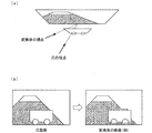
このような画質の悪化の他の例について、図11に基づいて説明する。図11は、入力視差画像から仮想視点画像に変換するときに、画質の悪化が発生する現象の一例を示す図である。図11の(a)は、物体を上から見たときの位置関係を示す図であり、元の視点位置および変換後の視点位置の関係を示す図である。図11の(b)は、入力視差画像から仮想視点画像に変換したとき、画質の悪化を示す図である。 Another example of such deterioration in image quality will be described with reference to FIG. FIG. 11 is a diagram illustrating an example of a phenomenon in which image quality deterioration occurs when an input parallax image is converted into a virtual viewpoint image. FIG. 11A is a diagram illustrating a positional relationship when an object is viewed from above, and is a diagram illustrating a relationship between an original viewpoint position and a converted viewpoint position. FIG. 11B is a diagram illustrating deterioration in image quality when an input parallax image is converted into a virtual viewpoint image.
まず、図11の(a)に示す元の視点の位置において、カメラで撮影して、図11の(b)の左図に示すような画像(以下、「元画像」と称する)を取得する。次に、元画像とは異なった視点(変換後の視点)から見たときの画像(以下、「変換後の画像」と称する)を作成する。具体的には、まず、元画像の各画素における奥行き量を求め、その奥行き量と変換後の視点位置とから内挿ベクトルを求める。次に、前記求められた内挿ベクトルに従って、図11の(b)に示すように、元画像の各画素を移動させることで、変換後の画像を生成する。 First, at the position of the original viewpoint shown in FIG. 11A, the image is taken by a camera, and an image as shown in the left figure of FIG. 11B (hereinafter referred to as “original image”) is acquired. . Next, an image (hereinafter referred to as “image after conversion”) when viewed from a different viewpoint from the original image (after-conversion viewpoint) is created. Specifically, first, a depth amount in each pixel of the original image is obtained, and an interpolation vector is obtained from the depth amount and the converted viewpoint position. Next, as shown in FIG. 11B, the converted image is generated by moving each pixel of the original image according to the obtained interpolation vector.
なお、前記奥行き量および内挿ベクトルの計算については、少なくとも2枚の元画像が必要であるが、詳細は後述するので、ここでその説明を省略する。 Note that the depth amount and the interpolation vector calculation require at least two original images, but details thereof will be described later, and the description thereof is omitted here.
しかし、前にも説明したように、奥行き量を精度よく計算することが難しい。そのため、奥行き量を求めるとき、物体の輪郭内であるにも関わらず、物体の輪郭の外側の奥行き量に近い値の奥行き量が算出されてしまう場合には、元画像上の物体輪郭外側における奥行き量が輪郭の内側に入り込む。その結果、その部分の画素の内挿ベクトルが物体の内挿ベクトルと違ってしまい、変換後の画像は物体の一部が欠けたような画像になる。 However, as described above, it is difficult to accurately calculate the depth amount. Therefore, when the depth amount is calculated, a depth amount close to the depth amount outside the object contour is calculated even though the depth amount is within the object contour. The amount of depth goes inside the contour. As a result, the interpolation vector of the pixel in that portion is different from the interpolation vector of the object, and the converted image becomes an image in which a part of the object is missing.
一方、奥行き量を求めるとき、物体の輪郭外であるにも関わらず、物体の輪郭の内側の奥行き量に近い値の奥行き量が算出されてしまう場合には、元画像上の物体輪郭内側における奥行き量が輪郭の外側にはみ出す。その結果、物体の周辺の画素が物体と一緒に移動してしまい、変換後の画像は物体の周辺に余計な絵柄がついたような画像になってしまう。図11の(b)の右図に示すように、変換後の画像では、手前の物体の下側が欠けており、一方、上側は背景の一部が手前の物体と一緒に移動してしまう。 On the other hand, when calculating the depth amount, if a depth amount close to the depth amount inside the contour of the object is calculated despite being outside the contour of the object, The depth amount protrudes outside the contour. As a result, the pixels around the object move together with the object, and the converted image becomes an image with an extra pattern around the object. As shown in the right diagram of FIG. 11B, in the converted image, the lower side of the foreground object is missing, while the upper side moves part of the background together with the foreground object.
このように、従来技術では、視差値または奥行き量を正確に計算することが難しいため、入力視差画像から仮想視点画像に変換するとき、画質の悪化が生じるという問題があった。 As described above, since it is difficult to accurately calculate the parallax value or the depth amount in the related art, there is a problem in that the image quality deteriorates when the input parallax image is converted into the virtual viewpoint image.
特許文献1には、複雑なシーンを撮影した入力視差画像に対して、画像内の特定範囲を選定し、その特定領域の視差値、もしくは奥行き量のみを調整することにより、期待しない領域の画素の視差値、もしくは奥行き量を変更しないようにすることが記載されているが、視差値または奥行き量が入力視差画像と正確に合っていない事によって発生する症状(画質の悪化)とその対策については記載されていない。 In Patent Document 1, a pixel in an unexpected region is selected by selecting a specific range in the image for an input parallax image obtained by capturing a complex scene and adjusting only the parallax value or the depth amount of the specific region. Although it is described that the parallax value or depth amount is not changed, symptoms (deterioration of image quality) that occur when the parallax value or depth amount does not match the input parallax image accurately and countermeasures Is not listed.
本発明は、上記の問題点に鑑みてなされたものであり、その目的は、入力視差画像から仮想視点画像に変換するときに生じる画質の悪化を軽減することのできる仮想視点画像生成装置、仮想視点画像生成方法、制御プログラム、記録媒体、および立体表示装置を提供することにある。 The present invention has been made in view of the above-described problems, and an object of the present invention is to provide a virtual viewpoint image generation apparatus, a virtual viewpoint that can reduce deterioration in image quality that occurs when an input parallax image is converted into a virtual viewpoint image. A viewpoint image generation method, a control program, a recording medium, and a stereoscopic display device are provided.
上記課題を解決するために、本発明に係る仮想視点画像生成装置は、仮想視点位置に応じた画像である新視点画像を生成する仮想視点画像生成装置であって、異なる視点位置での2以上の複数画像を取得する取得部と、前記取得部によって取得された画像のうち、1つの画像を基準画像として選択し、前記取得された複数画像から、新視点画像を生成するために前記基準画像の各画素の移動量を計算する移動量計算部と、前記移動量計算部によって計算された移動量に基づいて、前記基準画像の各画素を移動して、前記新視点画像を生成する新視点画像生成部と、前記新視点画像生成部によって生成された新視点画像の注目画素または複数の画素の集合である注目ブロックを特定し、前記注目画素または注目ブロックを含む所定の領域において、各画素における移動量のばらつきを求め、前記ばらつきの度合いに応じて、前記所定の領域に対する平滑化処理を実行し、前記注目画素または注目ブロックの値を、平滑化処理によって求めた平滑値に置き換える平滑化処理部とを備えていることを特徴としている。 In order to solve the above-described problem, a virtual viewpoint image generation device according to the present invention is a virtual viewpoint image generation device that generates a new viewpoint image that is an image corresponding to a virtual viewpoint position, and two or more at different viewpoint positions. An acquisition unit for acquiring a plurality of images, and selecting one image as a reference image from among the images acquired by the acquisition unit, and generating the new viewpoint image from the acquired plurality of images And a new viewpoint for generating the new viewpoint image by moving each pixel of the reference image based on the movement amount calculated by the movement amount calculator. An attention generating block which is a target pixel or a set of a plurality of pixels of the new viewpoint image generated by the image generation unit and the new viewpoint image generation unit is specified, and the target pixel or the target block is included in a predetermined region. Then, the variation of the movement amount in each pixel is obtained, and a smoothing process is performed on the predetermined area according to the degree of the variation, and the value of the target pixel or the target block is set to the smooth value obtained by the smoothing process. A smoothing processing unit to be replaced is provided.
また、上記課題を解決するために、本発明に係る仮想視点画像生成方法は、仮想視点位置に応じた画像である新視点画像を生成する仮想視点画像生成装置による仮想視点画像生成方法であって、異なる視点位置での2以上の複数画像を取得する取得ステップと、前記取得ステップにて取得された画像のうち、1つの画像を基準画像として選択し、前記取得された複数画像から、新視点画像を生成するために前記基準画像の各画素の移動量を計算する移動量計算ステップと、前記移動量計算ステップにて計算された移動量に基づいて、前記基準画像の各画素を移動して、前記新視点画像を生成する新視点画像生成ステップと、前記新視点画像生成ステップにて生成された新視点画像の注目画素または複数の画素の集合である注目ブロックを特定し、前記注目画素または注目ブロックを含む所定の領域において、各画素における移動量のばらつきを求め、前記ばらつきの度合いに応じて、前記所定の領域に対する平滑化処理を実行し、前記注目画素または注目ブロックの値を、平滑化処理によって求めた平滑値に置き換える平滑化処理ステップとを含むことを特徴としている。 In order to solve the above problems, a virtual viewpoint image generation method according to the present invention is a virtual viewpoint image generation method by a virtual viewpoint image generation device that generates a new viewpoint image that is an image according to a virtual viewpoint position. An acquisition step of acquiring two or more images at different viewpoint positions, and one image is selected as a reference image from the images acquired in the acquisition step, and a new viewpoint is selected from the acquired images A moving amount calculating step for calculating a moving amount of each pixel of the reference image to generate an image, and moving each pixel of the reference image based on the moving amount calculated in the moving amount calculating step; , A new viewpoint image generation step for generating the new viewpoint image, and a target block that is a target pixel or a set of a plurality of pixels of the new viewpoint image generated in the new viewpoint image generation step In the predetermined area including the target pixel or the target block, a variation in the movement amount in each pixel is obtained, and a smoothing process is performed on the predetermined area according to the degree of the variation, and the target pixel or the target block And a smoothing step that replaces the value with a smooth value obtained by the smoothing process.
新視点画像において、物体の一部分が欠けたり、物体の輪郭の周囲に余計な絵柄がついたりする症状は、複数画像の同じ被写体の部位同士で画素ごとに求めた移動量が物体の輪郭に沿っていないことが原因なので、物体の輪郭付近で生じやすい。つまり、物体の輪郭付近では、物体と背景とが隣接しているために、物体の輪郭を境として、移動量の差が大きくなりやすい。この差が、注目画素または注目ブロックが物体に属しているのか、背景に属しているのかについて、誤判定を誘発する。画素ごとの移動量の差(ばらつき)が大きい領域ほど、上記症状が目立ってくる。 In the new viewpoint image, the symptom that a part of the object is missing or an extra pattern is added around the outline of the object is that the amount of movement calculated for each pixel of the same subject part of the multiple images follows the outline of the object This is likely to occur near the contour of the object. That is, since the object and the background are adjacent to each other in the vicinity of the contour of the object, the difference in movement amount tends to increase with the contour of the object as a boundary. This difference induces an erroneous determination as to whether the pixel of interest or the block of interest belongs to the object or the background. The symptom becomes more conspicuous as the difference (variation) in the movement amount for each pixel is larger.
上記の構成によれば、上記の症状が目立ちやすい領域である、移動量のばらつきの大きい画素を含む領域において、上記領域に対する平滑化処理を実行することができる。よって、上記の症状が目立ちやすい領域における画像(特に、輪郭のずれ)が、上記平滑化処理によってぼかされ、目立たなくなるため、画質の悪化を軽減することができるという効果を奏する。 According to said structure, the smoothing process with respect to the said area | region can be performed in the area | region containing the pixel with the big variation | change_quantity of movement amount which is an area | region where said symptom is conspicuous. Therefore, an image (particularly, a contour shift) in an area in which the above-described symptom is conspicuous is blurred by the smoothing process and becomes inconspicuous, so that it is possible to reduce deterioration in image quality.
なお、異なる視点位置での画像が、少なくとも2枚あるならば、移動量計算部は、同じ被写体の同じ部位の各画像上での位置を比較することによって、その部位の奥行き情報を求めることができる。また、上記異なる視点位置とは別の新視点位置に対応して、上記部位の画素を移動させる必要のある移動量を、移動量計算部は、視点位置の変化量と求めた奥行き情報とを使って得ることができる。 If there are at least two images at different viewpoint positions, the movement amount calculation unit can obtain the depth information of the part by comparing the positions of the same part of the same subject on each image. it can. In addition, the movement amount calculation unit calculates the amount of movement required to move the pixels of the part corresponding to a new viewpoint position different from the different viewpoint position, and the amount of change of the viewpoint position and the obtained depth information. You can get it using.
なお、1つの注目画素ではなく、複数の画素の集合である注目ブロックを採用すると、画像のサイズが大きい(画素の数が多い)場合に、処理速度を向上することができるなどの効果を奏する。 In addition, when an attention block that is a set of a plurality of pixels is used instead of a single attention pixel, there is an effect that the processing speed can be improved when the image size is large (the number of pixels is large). .
また、上記仮想視点画像生成装置では、前記平滑化処理部は、前記ばらつきの度合いに応じて、平滑化の強度を決めておき、その強度に応じて平滑化することが好ましい。 In the virtual viewpoint image generation device, it is preferable that the smoothing processing unit determines a smoothing strength in accordance with the degree of variation, and performs smoothing in accordance with the strength.
上記の構成によれば、画質の悪化の目立つ程度に応じて画素の値を平滑化することができる。すなわち、画質の悪化が発生した場合、画質の悪化が発生した領域に含まれる注目画素または注目ブロックの値を一律に平滑化させず、画質の悪化の目立つ程度に応じて、平滑化の強さを変更することができる。よって、画像の明らかさを最大限に保つとともに画質の悪化を軽減することができるという効果を奏する。 According to the above configuration, the pixel value can be smoothed according to the degree of conspicuous deterioration in image quality. That is, when image quality deterioration occurs, the value of the target pixel or target block included in the area where the image quality deterioration has occurred is not uniformly smoothed. Can be changed. Therefore, there is an effect that image clarity can be kept to the maximum and deterioration of image quality can be reduced.
また、上記仮想視点画像生成装置では、前記平滑化処理部は、前記ばらつきの度合いとして、前記移動量の最大値および最小値の差の絶対値を求めることことが好ましい。 In the virtual viewpoint image generation device, it is preferable that the smoothing processing unit obtains an absolute value of a difference between the maximum value and the minimum value of the movement amount as the degree of variation.
上記の構成によれば、前記移動量のばらつきの度合いを移動量の最大値および最小値の差の絶対値によって求めることができる。よって、前記ばらつきの度合いを標準偏差などの演算によって求める場合に比べて、複雑な演算が要らず、処理速度が速くなる。さらに、前記平滑化処理部を回路で実現した場合には、演算器等が少なくて済むので、回路規模が小さくなるという効果を奏する。 According to said structure, the dispersion | variation degree of the said moving amount can be calculated | required with the absolute value of the difference of the maximum value of moving amount, and the minimum value. Therefore, compared to a case where the degree of variation is obtained by calculation such as standard deviation, no complicated calculation is required and the processing speed is increased. Further, when the smoothing processing unit is realized by a circuit, there is an effect that the circuit scale is reduced because fewer arithmetic units and the like are required.
なお、上記仮想視点画像生成装置は、コンピュータによって実現してもよく、この場合には、コンピュータを上記仮想視点画像生成装置の各手段として動作させることにより、上記仮想視点画像生成装置をコンピュータにて実現させる制御プログラム、およびそれを記録したコンピュータ読み取り可能な記録媒体も本発明の範疇に入る。 The virtual viewpoint image generation apparatus may be realized by a computer. In this case, the virtual viewpoint image generation apparatus is operated by the computer by causing the computer to operate as each unit of the virtual viewpoint image generation apparatus. A control program to be realized and a computer-readable recording medium on which the control program is recorded also fall within the scope of the present invention.
また、上記仮想視点画像生成装置を備え、前記仮想視点画像生成装置が生成した仮想視点画像を用いて、立体表示を行う立体表示装置であれば、上記仮想視点画像生成装置と同様の効果を奏する。 Further, if the stereoscopic display device includes the virtual viewpoint image generation device and performs stereoscopic display using the virtual viewpoint image generated by the virtual viewpoint image generation device, the same effects as the virtual viewpoint image generation device can be obtained. .
以上のように、本発明は、生成された新視点画像の注目画素または複数の画素の集合である注目ブロックを特定し、上記注目画素または注目ブロックを含む所定の領域において、各画素における移動量のばらつきの度合いに応じて、前記領域に対する平滑化処理を実行することを特徴としている。 As described above, the present invention identifies a target pixel of the generated new viewpoint image or a target block that is a set of a plurality of pixels, and moves in each pixel in a predetermined region including the target pixel or target block. A smoothing process is performed on the area in accordance with the degree of variation.
したがって、物体の一部分が欠けたり、物体の輪郭の周囲に余計な絵柄がついたりする症状が目立ちやすい領域における画像が、上記平滑化処理によってぼかされ、目立たなくなるため、画質の悪化を軽減することができるという効果を奏する。 Therefore, an image in an area where a symptom in which a part of the object is missing or an extra pattern around the outline of the object is easily noticeable is blurred by the above-described smoothing process and becomes inconspicuous. There is an effect that can be.
〔実施形態1〕
本発明の一実施形態に係る仮想視点画像生成装置1について、図1から図6に基づいて説明すれば、以下のとおりである。
Embodiment 1
The virtual viewpoint image generation device 1 according to an embodiment of the present invention will be described below with reference to FIGS.
(処理概要)
まず、本実施形態に係る仮想視点画像生成装置1が、画質の悪化を軽減する処理の概要を説明する。
(Outline of processing)
First, an outline of processing in which the virtual viewpoint image generation device 1 according to the present embodiment reduces deterioration in image quality will be described.
新視点画像において、物体の一部分が欠けたり、物体の輪郭の周囲に余計な絵柄がついたりする症状は、複数画像の同じ被写体の部位同士で画素ごとに求めた内挿ベクトル(移動量)が物体の輪郭に沿っていないことが原因なので、物体の輪郭付近で生じやすい。つまり、物体の輪郭付近では、物体と背景とが隣接しているために、物体の輪郭を境として、内挿ベクトルの差が大きくなりやすい。この差が、注目画素または注目ブロックが物体に属しているのか、背景に属しているのかについて、誤判定を誘発する。したがって、画素ごとの内挿ベクトルの差が大きくなるほど、上記症状が目立ってくる。 In the new viewpoint image, the symptom that a part of the object is missing or an extra pattern is added around the outline of the object is that the interpolation vector (movement amount) obtained for each pixel of the same subject part in multiple images is It is likely to occur near the contour of the object because it is not along the contour of the object. That is, since the object and the background are adjacent to each other in the vicinity of the contour of the object, the difference between the interpolation vectors tends to increase with the contour of the object as a boundary. This difference induces an erroneous determination as to whether the pixel of interest or the block of interest belongs to the object or the background. Therefore, the above-mentioned symptom becomes more conspicuous as the difference in the interpolation vector for each pixel increases.
ここで、内挿ベクトルとは、仮想視点画像を生成するために、入力視差画像における画素毎の移動量を示すものである。すなわち、内挿ベクトルは、仮想視点位置(以下、「新視点位置」と称する場合がある)から見た場合の画像を入力視差画像から生成する場合に、入力視差画像上の各画素をどれだけ動かせばよいかを表したパラメータである。 Here, the interpolation vector indicates a movement amount for each pixel in the input parallax image in order to generate a virtual viewpoint image. That is, the interpolation vector indicates how much each pixel on the input parallax image is generated when an image viewed from a virtual viewpoint position (hereinafter sometimes referred to as “new viewpoint position”) is generated from the input parallax image. This parameter indicates whether it should be moved.
また、上記入力視差画像とは、同一の物体を両眼で見た場合、あるいは2つのカメラで撮影した場合における、左目または左側カメラの視点位置に対応した左画像、および右目のまたは右側カメラの視点位置に対応した右画像の少なくとも一方を指す。 The input parallax images are the left image corresponding to the viewpoint position of the left eye or the left camera and the right eye or the right camera when the same object is viewed with both eyes or taken with two cameras. It refers to at least one of the right images corresponding to the viewpoint position.
よって、本発明に係る仮想視点画像生成装置1は、入力視差画像から変換された変換後の画像(以下、「新視点画像」と称する場合がある)に対して、所定の領域において、内挿ベクトルのばらつき(例えば最大値および最小値の差の絶対値)が大きい場合、その領域に対して平滑化処理を実行することによって、画像の当該領域がぼかされ、画質の悪化を軽減する。 Therefore, the virtual viewpoint image generation device 1 according to the present invention interpolates a converted image converted from an input parallax image (hereinafter sometimes referred to as “new viewpoint image”) in a predetermined region. When the variation of the vector (for example, the absolute value of the difference between the maximum value and the minimum value) is large, the region of the image is blurred by executing the smoothing process on the region, thereby reducing the deterioration of the image quality.
具体的には、仮想視点画像生成装置1は、まず、新視点画像を作成する際の画素毎の内挿ベクトルを、奥行き量と新視点位置とから求め、画素毎に保存しておく。 Specifically, the virtual viewpoint image generation device 1 first obtains an interpolation vector for each pixel when creating a new viewpoint image from the depth amount and the new viewpoint position, and stores the obtained interpolation vector for each pixel.
そして、前記求められた内挿ベクトルに従って、入力視差画像における各画素を移動させることで、新視点画像を生成する。次に、新視点画像に対して、ある画素を中心とする所定の領域内の内挿ベクトルを参照する。そのうち、内挿ベクトルのばらつき(例えば最小値および最大値の差の絶対値)が、あらかじめ決めておいた閾値以上の場合は、当該領域内における各画素値の平滑化された値(例えば、平均値)を求め、上記領域に含まれる注目画素の新しい画素値とする。なお、注目画素は1画素でもよいが、複数の画素の集合である注目ブロックを注目画素として扱ってもよい。 Then, a new viewpoint image is generated by moving each pixel in the input parallax image according to the obtained interpolation vector. Next, with respect to the new viewpoint image, an interpolation vector in a predetermined area centered on a certain pixel is referred to. Among them, when the variation of the interpolation vector (for example, the absolute value of the difference between the minimum value and the maximum value) is equal to or greater than a predetermined threshold value, a smoothed value (for example, an average value) of each pixel value in the region Value) to obtain a new pixel value of the target pixel included in the region. Note that the target pixel may be one pixel, but a target block that is a set of a plurality of pixels may be treated as the target pixel.
内挿ベクトルのばらつきを調べて必要に応じて平滑化する処理を、新視点画像を構成する全ての画素について繰り返す。 The process of examining the variation of the interpolation vector and smoothing as necessary is repeated for all the pixels constituting the new viewpoint image.
最後に、新視点画像の一部画素の画素値を前記平滑された値に変更して、仮想視点画像を生成する。 Finally, the virtual viewpoint image is generated by changing the pixel values of some pixels of the new viewpoint image to the smoothed values.
以上の処理によって、生成された仮想視点画像において、内挿ベクトルのばらつきが大きい領域の画像が、平滑化によってぼかされ、前記のような画質の悪化の症状が目立たなくなり、画質の悪化を軽減することができる。 By the above processing, in the generated virtual viewpoint image, the image of the region where the variation of the interpolation vector is large is blurred by the smoothing so that the above-mentioned symptoms of the deterioration of the image quality become inconspicuous and the deterioration of the image quality is reduced. can do.
(仮想視点画像生成装置1の構成)
以下では、仮想視点画像生成装置1の要部構成について、図1に基づいて説明する。
(Configuration of Virtual Viewpoint Image Generation Device 1)
Below, the principal part structure of the virtual viewpoint image generation apparatus 1 is demonstrated based on FIG.
図1は、仮想視点画像生成装置1の要部構成を示すブロック図である。図1に示すように、仮想視点画像生成装置1は、画像取得部10(取得部)、一致ブロック探索部20、奥行き量計算部30、新視点位置取得部40、内挿ベクトル計算部50(移動量計算部)、新視点画像生成部60、境界平滑部70(平滑化処理部)を備えている。
FIG. 1 is a block diagram showing a main configuration of the virtual viewpoint image generation device 1. As illustrated in FIG. 1, the virtual viewpoint image generation device 1 includes an image acquisition unit 10 (acquisition unit), a matching
各部(10〜70)が行う処理の具体例については、後で詳述するので、ここでは各部(10〜70)の概要を説明する。 A specific example of the processing performed by each unit (10 to 70) will be described in detail later, so the outline of each unit (10 to 70) will be described here.
画像取得部10は、異なる視点位置での2以上の複数画像、例えば、入力視差画像である左画像および右画像を取得するものである。ここで、左画像および右画像は、被写体の撮影面の水平方向と平行する線における2つの視点位置から該被写体を撮影して得られたものである。前記左画像および右画像の取得方法については、特に限定されず、例えば、仮想視点画像生成装置1に内蔵されている双眼カメラ(不図示)によって撮影された画像を取得してもよいし、通信手段(不図示)によって配信サーバから取得してもよい。画像取得部10は、取得した左画像および右画像を一致ブロック探索部20に送信する。
The
一致ブロック探索部20は、画像取得部10から受信した左画像と右画像とから、一致する部分(一致ブロック)を水平方向に見て探索するものである。具体的には、例えば、左画像を基準画像とする。一致ブロック探索部20は、まず、左画像を複数のブロックに分割し、右画像から前記分割されたブロックと一致するブロックを水平方向に見て探索する。そして、一致ブロック探索部20は、左画像および右画像のそれぞれにおける一致ブロックの左上の座標値を奥行き量計算部30に送信する。
The matching
奥行き量計算部30は、一致ブロック探索部20から受信した各左画像および右画像における座標値から、差を計算して、奥行き量を求めるものである。そして、奥行き量計算部30は、求めた奥行き量を内挿ベクトル計算部50に送信する。
The depth
新視点位置取得部40は、生成する新視点画像の新視点位置を取得する。なお、新視点位置の取得方法は特に限定されず、例えば、予め決められた視点位置を仮想視点画像生成装置1に備えられている記憶部(不図示)から取得してもよいし、ユーザから操作部(不図示)によって指定されたものを取得してもよい。そして、新視点位置取得部40は、取得した新視点位置を内挿ベクトル計算部50に送信する。
The new viewpoint
内挿ベクトル計算部50は、受信した奥行き量と新視点位置とから、前記新視点位置における新視点画像を生成するために、基準画像としての左画像における画素毎の移動量、すなわち内挿ベクトルを求めるものである。そして、内挿ベクトル計算部50は、求めた画素毎の内挿ベクトルを新視点画像生成部60に送信する。
The interpolation
新視点画像生成部60は、前記新視点位置から見た場合の新視点画像を生成するものである。具体的には、新視点画像生成部60は、画像取得部10から基準画像としての左画像を取得し、内挿ベクトル計算部50から受信した画素毎の内挿ベクトルに基づいて、前記左画像における各画素を移動させ、新視点画像を生成する。そして、新視点画像生成部60は、生成した新視点画像を、各画素の内挿ベクトルとともに、境界平滑部70に送信する。
The new viewpoint
境界平滑部70は、所定の領域内の各画素における内挿ベクトルの最大値および最小値の差が大きい場合、上記所定の領域に対する平滑化処理を実行し、上記注目画素または注目ブロックの値を、平滑化処理によって求めた平滑値に置き換えて、仮想視点画像を生成するものである。
When the difference between the maximum value and the minimum value of the interpolation vector at each pixel in the predetermined area is large, the
(処理の流れ)
以下では、仮想視点画像生成装置1の各部(10〜70)の処理詳細について、図2〜6に基づいて説明する。
(Process flow)
Hereinafter, processing details of each unit (10 to 70) of the virtual viewpoint image generation device 1 will be described with reference to FIGS.
まず、図2に基づいて、仮想視点画像生成装置1の処理の流れを説明する。図2は、仮想視点画像生成装置1が左画像および右画像を取得してから、仮想視点画像を生成するまでの処理の流れを示すフローチャートである。 First, the flow of processing of the virtual viewpoint image generation device 1 will be described with reference to FIG. FIG. 2 is a flowchart showing a flow of processing from when the virtual viewpoint image generation device 1 acquires a left image and a right image to when a virtual viewpoint image is generated.
<一致ブロック探索>
図2に示すように、まず、画像取得部10は、左画像および右画像を取得する(S101)。
<Match block search>
As shown in FIG. 2, first, the
そして、一致ブロック探索部20は、左画像および右画像のそれぞれにおける一致ブロックを探索する(S102)。
Then, the matching
具体的には、まず、一致ブロック探索部20は、図3に示すように、左画像をn×n画素(nは1以上の整数である)の矩形領域(n)に分割する。図3は、左画像を分割する例を示す図である。そして、一致ブロック探索部20は、分割した領域の1つと水平位置および垂直位置が同じであるn×n画素の矩形領域(n)を右画像上にも設定する。
Specifically, first, the matching
次に、一致ブロック探索部20は、左画像および右画像のそれぞれのn×n画素の矩形領域(n)を中心としたm×m画素の矩形領域(m)を設定する。ただし、mはn以上の整数である。
Next, the matching
以下では、n×n画素の矩形領域(n)とは別に、m×m画素の矩形領域(m)を設定する理由について説明する。 Hereinafter, the reason for setting the rectangular area (m) of m × m pixels separately from the rectangular area (n) of n × n pixels will be described.
一致ブロック探索部20が一致ブロック探索を行うときの矩形領域は、ある程度のサイズまではサイズが大きくなるほど一致の精度が上がると考えられる。これはサイズが大きい方が絵柄の情報量が多く、その多い情報量に対して一致具合を確認していくので、結果的に一致の精度が高くなるからである。そのため、探索するときの矩形のサイズは大きい方が有利である。
It is considered that the accuracy of matching increases as the size of the rectangular area when the matching
ところが、単純に矩形領域のサイズを大きくすると、結果の奥行き量の粒度が大きくなってしまう。例えば矩形領域のサイズを64×64画素(以下では、矩形領域(64)と称する)などと大きいサイズにすると、結果の奥行き量も矩形領域(64)内は同じ奥行き量になるので、奥行き量が64×64画素単位でガタガタのモザイク画像のような粗い結果になる。これではどんなに一致ブロック探索の精度が良くても、入力された画像の絵柄に細かく沿った奥行き量にはならない。 However, simply increasing the size of the rectangular area increases the granularity of the resulting depth. For example, when the size of the rectangular area is set to a large size such as 64 × 64 pixels (hereinafter, referred to as a rectangular area (64)), the resulting depth amount also becomes the same depth amount in the rectangular area (64). Produces a rough result like a rattling mosaic image in units of 64 × 64 pixels. In this way, no matter how accurate the matching block search is, the amount of depth along the pattern of the input image is not fine.
以上の2点(探索の精度および画質の鮮明さ)を両立させるために、一致ブロック探索の探索自体は大きいサイズのm×m画素で行い、それによって求められた奥行き量は小さいサイズのn×n画素に反映させる。これによって、探索の精度が良く、結果の奥行き量は細かく入力画像の絵柄に沿ったものにすることができる。 In order to achieve both of the above two points (search accuracy and image clarity), the matching block search itself is performed with m × m pixels of a large size, and the depth amount thus obtained is a small size of n × m. Reflected in n pixels. As a result, the accuracy of the search is good, and the resulting depth amount can be finely matched to the pattern of the input image.
小さい方の矩形領域(n)のサイズは、理想的には1×1画素である。しかしながら、ソフトウェアで行うときにはそれでも問題ないが、回路を組んでハードウェアで行う場合には、そうすると回路がずいぶん増えてしまう可能性があるため、nは1以上の整数であることが好ましい。 The size of the smaller rectangular area (n) is ideally 1 × 1 pixel. However, there is no problem when it is performed by software. However, when the circuit is assembled and performed by hardware, there is a possibility that the number of circuits may increase considerably. Therefore, n is preferably an integer of 1 or more.
そして、一致ブロック探索部20は、左画像上のm×m画素の矩形領域(m)と、右画像上のm×m画素の矩形領域(m)との一致度を計算する。前記一致度とは、左画像上の矩形領域(m)に含まれるm×m画素の各画素値と右画像上の矩形領域(m)に含まれるm×m画素の各画素値との違いの度合いを示す値である。前記一致度は、下記の式(1)のように矩形領域(m)の各画素値の差の絶対値の総和で求められる。
Then, the matching

ここで、RおよびLは、それぞれ右画像の矩形領域(m)および左画像の矩形領域(m)に含まれる各画素の画素値を示し、(x,y)は画素の座標値を示す。例えば、R(x,y)は右画像における座標(x,y)に位置する画素の画素値である。 Here, R and L indicate the pixel value of each pixel included in the rectangular area (m) of the right image and the rectangular area (m) of the left image, respectively, and (x, y) indicate the coordinate value of the pixel. For example, R (x, y) is a pixel value of a pixel located at coordinates (x, y) in the right image.
式(1)によれば、求めた一致度が0に近いほど、一致度が高いことになる。 According to Expression (1), the closer the calculated matching degree is to 0, the higher the matching degree.
さらに、一致ブロック探索部20は、右画像上のn×n画素の矩形領域(n)を、水平方向において予め設定された1画素以上のずらし量ずつ右へずらしながら、それぞれの矩形領域(n)を中心とするm×m画素の矩形領域(m)を新たに取得し、上記の方法で、前記取得された左画像における矩形領域(m)との一致度を計算する。
Further, the matching
上記ずらし量は、1画素以上の値であればよいが、計算された奥行き量の精度を高く求める場合には、より小さい値(例えば、1画素)を設定することが好ましい。 The shift amount may be a value of one pixel or more. However, when the calculated depth amount is highly accurate, it is preferable to set a smaller value (for example, one pixel).
その理由を、一致ブロック探索で左画像が基準の場合を例として説明する。左画像が基準の場合には、左画像についてはn×n画素毎に画面全体を分割する。よって、左画像について、n画素分ずつ処理を行う。一方、右画像において、左画像上の矩形領域(m)と同じサイズのm×m画素の矩形領域(m)を設定して、左画像上の矩形領域(m)との比較を行う。ここで、右画像上の矩形領域(m)をずらす画素数は任意に設定することができるが、ずらし量によって求められる奥行き量の細かさ(精度)が変わってくる。言い換えると、上記ずらし量が小さいほど、奥行き量の精度が高くなる。 The reason will be described by taking the case where the left image is the reference in the matching block search as an example. When the left image is a reference, the entire screen of the left image is divided every n × n pixels. Therefore, the left image is processed n pixels at a time. On the other hand, in the right image, a rectangular area (m) of m × m pixels having the same size as the rectangular area (m) on the left image is set and compared with the rectangular area (m) on the left image. Here, the number of pixels for shifting the rectangular area (m) on the right image can be arbitrarily set, but the fineness (accuracy) of the depth amount determined by the shift amount varies. In other words, the smaller the shift amount, the higher the accuracy of the depth amount.
従って、一致ブロック探索の処理速度の向上、および、求める奥行き量の精度の向上を両立するために、n×n画素(およびm×m画素)の矩形領域を粗く(大きく)設定するとともに、上記ずらし量を細かく(小さく)設定することが好ましい。 Therefore, in order to improve both the processing speed of the matching block search and the accuracy of the depth amount to be obtained, the rectangular area of n × n pixels (and m × m pixels) is set coarsely (largely), and the above It is preferable to set the shift amount finely (smallly).
次に、一致ブロック探索部20は、一致度が最も小さい右画像上の矩形領域(m)に含まれた矩形領域(n)と、前記左画像上の矩形領域(m)に含まれた矩形領域(n)とを、一致ブロックと判定する。そして、一致ブロック探索部20は、前記一致ブロックと判定した右画像における矩形領域(n)の左上座標値(xR,y)と、前記左画像における矩形領域(n)の左上座標値(xL,y)とを一致ブロック対応関係として対応付けて記憶する。
Next, the matching
あるいは、一致度が最も小さい矩形領域(m)を一致ブロックと判定し、一致ブロックと判定した右画像における矩形領域(m)の左上座標値(xR,y)と、前記左画像における矩形領域(m)の左上座標値(xL,y)とを一致ブロック対応関係として対応付けて記憶してもよい。 Alternatively, the rectangular area (m) having the smallest matching degree is determined as a matching block, and the upper left coordinate value (x R , y) of the rectangular area (m) in the right image determined to be the matching block, and the rectangular area in the left image The upper left coordinate value (x L , y) of (m) may be stored in association with the matching block correspondence.
それから、一致ブロック探索部20は、左画像上のすべての矩形領域(n)に対して、上述と同じように、右画像上の矩形領域(n)との一致ブロック対応関係を求める。最後に、一致ブロック探索部20は、前記記憶された一致ブロック対応関係を奥行き量計算部30に送信する。
Then, the matching
<奥行き量計算>
次に、奥行き量計算部30は、前記一致ブロック対応関係にある左画像の矩形領域(n)の左上座標値と、右画像の矩形領域(n)の左上座標値とから、奥行き量を計算する(S103)。具体的には、図4に基づいて説明する。図4は、一致ブロックにより奥行き量を計算する例を説明する図である。図4の(a)は右画像を示す図であり、図4の(b)は左画像を示す図である。
<Depth calculation>
Next, the depth
例えば、前記一致ブロック対応関係にある左画像の矩形領域(n)の左上座標値を(xL,y)とし、右画像の矩形領域(n)の左上座標値を(xR,y)とする。図4に示すように、奥行き量計算部30は、下記の式(2)によって奥行き量を求める。
For example, the upper left coordinate value of the rectangular area (n) of the left image in the matching block correspondence relationship is (x L , y), and the upper left coordinate value of the rectangular area (n) of the right image is (x R , y). To do. As shown in FIG. 4, the depth
奥行き量=xR−xL ・・・(2)
次に、奥行き量計算部30は、前記求めた奥行き量を、左画像において、注目していた矩形領域(n)に含まれた全ての画素、すなわちn×n個の各画素に割り当てる。
Depth amount = x R −x L (2)
Next, the depth
そして、奥行き量計算部30は、左画像上のすべての矩形領域(n)の左上座標値について奥行き量を求めることによって、左画像上のすべての画素に奥行き量が割り当てられる。それから、奥行き量計算部30は、左画像における各画素に割り当てられた奥行き量(以下、「各画素の奥行き量」と称する場合がある)を内挿ベクトル計算部50に送信する。
Then, the depth
なお、上の例では、矩形領域(n)および矩形領域(m)は、正方形であるが、それに限らず、長方形であってもよい。さらに、矩形領域(m)のサイズについては、矩形領域(n)と同じサイズであってもよい。 In the above example, the rectangular area (n) and the rectangular area (m) are squares, but are not limited thereto, and may be rectangular. Furthermore, the size of the rectangular area (m) may be the same size as the rectangular area (n).
<内挿ベクトル計算>
次に、新視点位置取得部40は、生成する新視点画像の新視点位置を取得する(S104)。前記新視点位置を表す値は、図5に基づいて説明する。図5は、視点位置を表す値を示す図である。
<Interpolation vector calculation>
Next, the new viewpoint
図5に示すように、左画像の視点位置に相当する新視点位置を0.0とし、右画像の視点位置に相当する新視点位置を1.0とする。また、他の新視点位置は、前記左画像および右画像の視点位置に対する相対値によって表される。 As shown in FIG. 5, the new viewpoint position corresponding to the viewpoint position of the left image is set to 0.0, and the new viewpoint position corresponding to the viewpoint position of the right image is set to 1.0. The other new viewpoint positions are represented by relative values with respect to the viewpoint positions of the left image and the right image.
例えば、図5に示すように、左画像および右画像の中間の位置から見た新視点画像を作成したい場合には、新視点位置を0.5と設定し、右画像よりさらに右側から見た画像を作成したい場合には、新視点位置を1.5と設定する。さらに、左画像よりさらに左側から見た画像を作成したい場合には、新視点位置を−0.5と設定する。 For example, as shown in FIG. 5, when creating a new viewpoint image viewed from an intermediate position between the left image and the right image, the new viewpoint position is set to 0.5 and viewed from the right side of the right image. When creating an image, the new viewpoint position is set to 1.5. Furthermore, when it is desired to create an image viewed from the left side of the left image, the new viewpoint position is set to -0.5.
そして、新視点位置取得部40は、取得した新視点位置を内挿ベクトル計算部50に送信する。
Then, the new viewpoint
次に、内挿ベクトル計算部50は、奥行き量検索部30から取得された各画素の奥行き量と、新視点位置取得部40から取得された新視点位置とから、左画像の各画素の内挿ベクトルを求める(S105)。具体的には、内挿ベクトル計算部50は、下記の式(3)に基づいて、各画素の内挿ベクトルを求める。
Next, the interpolation
(内挿ベクトル)=(奥行き量)×(新視点位置) ・・・(3)
そして、内挿ベクトル計算部50は、前記式(3)によって求めた各画素の内挿ベクトルを新視点画像生成部60に送信する。
(Interpolation vector) = (depth amount) × (new viewpoint position) (3)
Then, the interpolation
<新視点画像生成>
次に、新視点画像生成部60は、画像取得部10から左画像を取得する。また、新視点画像生成部60は、内挿ベクトル計算部50から、左画像における各画素の内挿ベクトルを取得する。
<New viewpoint image generation>
Next, the new viewpoint
続いて、新視点画像生成部60は、前記新視点位置から見た場合の新視点画像を生成する(S106)。具体的には、例えば、左画像の注目する1画素を(x,y)とし、その注目する1画素における内挿ベクトルをVとする。新視点画像生成部60は、前記注目する1画素(x,y)を(x+V,y)の位置に移動させる。そして、新視点画像生成部60は、前記と同じように、左画像におけるすべて画素について、上記の移動を行わせる。よって、新視点位置から見た場合の新視点画像が生成される。生成された新視点画像については、図6に基づいて説明する。
Subsequently, the new viewpoint
図6は、左画像における画素を移動させることで、新視点画像を生成し、平滑化を行うことで、仮想視点画像を生成する場合の画像の変化を示す図である。図6の(a)は、入力視差画像としての左画像を示す図である。図6の(b)は、左画像における画素を移動させることによって生成された新視点画像を示す図であり、例えば、図5に示す−0.5の新視点位置から上記左画像を見た場合の新視点画像を示している。また、図6の(c)は、仮想視点画像を生成するために、後述の平滑化処理を実行する対象領域を示す図である。 FIG. 6 is a diagram illustrating changes in an image when a virtual viewpoint image is generated by generating a new viewpoint image by moving pixels in the left image and performing smoothing. (A) of FIG. 6 is a figure which shows the left image as an input parallax image. FIG. 6B is a diagram illustrating a new viewpoint image generated by moving a pixel in the left image. For example, the left image is viewed from a new viewpoint position of −0.5 illustrated in FIG. In this case, a new viewpoint image is shown. Moreover, (c) of FIG. 6 is a figure which shows the object area | region which performs the below-mentioned smoothing process, in order to produce | generate a virtual viewpoint image.
図6に示すように、図6の(a)に示す左画像における各画素を内挿ベクトルによって移動させた後、図6の(b)に示す新視点画像が生成される。 As shown in FIG. 6, after each pixel in the left image shown in FIG. 6A is moved by the interpolation vector, a new viewpoint image shown in FIG. 6B is generated.
そして、新視点画像生成部60は、画素の移動と同時に、内挿ベクトルについても、元の画素から移動後の画素へ値を移しておく。つまり、移動後の画素と内挿ベクトルとが対応付けられて記憶される。この内挿ベクトルは、後述の境界平滑部70による平滑化処理で必要になる。
Then, the new viewpoint
それから、新視点画像生成部60は、生成された新視点画像、および、各画素の内挿ベクトルを境界平滑部70に送信する。
Then, the new viewpoint
なお、左画像における画素を移動させる際、複数の画素が同じ座標位置へ移動することが発生する場合がある。その場合には、それぞれの元の画素における奥行き量を参照して、移動することが好ましい。具体的には、奥行き量が最も小さい画素の移動を優先して行う。これは、奥行き量が小さいほど、その奥行き量に対応する画素がより手前にあることを表しており、異なる奥行き量に対応する複数の画素が重なったときは、奥の画素は手前の画素に隠されるべきであるためである。 In addition, when moving the pixel in the left image, a plurality of pixels may move to the same coordinate position. In that case, it is preferable to move by referring to the depth amount in each original pixel. Specifically, the movement of the pixel having the smallest depth amount is given priority. This means that the smaller the depth amount, the closer the pixel corresponding to that depth amount is, and when multiple pixels corresponding to different depth amounts overlap, the back pixel is replaced by the previous pixel. Because it should be hidden.
ここで、内挿ベクトルを参照するのではなく、それ以前に求めた奥行き量を確認する必要がある。それは、内挿ベクトルは奥行き量に加えて視点位置も加わった値であるため、奥行き量と視点位置との正負関係が逆になる場合には、内挿ベクトルの大小と奥行き量の関係が逆転してしまうからである。 Here, instead of referring to the interpolation vector, it is necessary to confirm the depth amount obtained before that. This is because the interpolation vector is a value in which the viewpoint position is added in addition to the depth amount. Therefore, when the positive / negative relationship between the depth amount and the viewpoint position is reversed, the relationship between the size of the interpolation vector and the depth amount is reversed. Because it will do.
例えば、
(A)手前の物体の奥行き量=20
(B)奥の背景の奥行き量=100
とし、新視点位置が左画像より左側の−1.5とすると、
(A’)手前の物体の内挿ベクトル=−30(=20×−1.5)
(B’)奥の背景の内挿ベクトル=−150(=100×−1.5)
となる。
For example,
(A) Front object depth = 20
(B) Depth amount of back background = 100
If the new viewpoint position is -1.5 on the left side of the left image,
(A ′) Interpolation vector of front object = −30 (= 20 × −1.5)
(B ′) Backside background interpolation vector = −150 (= 100 × −1.5)
It becomes.
この場合、奥行き量の大小関係と、内挿ベクトルの大小関係とは逆になっていることがわかる。 In this case, it can be seen that the magnitude relationship between the depth amounts is opposite to the magnitude relationship between the interpolation vectors.
次に、奥行き量が小さいほど、その奥行き量に対応する画素がより手前にある理由について説明する。 Next, the reason why the smaller the depth amount is, the closer the pixel corresponding to the depth amount is.
その前に、まず、画面に対して立体像が結像する位置について説明する。立体像が結像する位置は、同じ物体が左画像上と右画像上とで、どの位置に表示されているかによって決まる。例えば、
(A)左画像上の位置に比べて右画像上の位置が右側にある場合には、画面より奥側に結像される。
Before that, first, a position where a stereoscopic image is formed on the screen will be described. The position at which the stereoscopic image is formed is determined by the position where the same object is displayed on the left image and the right image. For example,
(A) When the position on the right image is on the right side compared to the position on the left image, the image is formed on the back side from the screen.
(B)左画像上の位置と右画像上の位置とが同じ場合には、画面の位置に結像される。 (B) When the position on the left image and the position on the right image are the same, an image is formed at the position of the screen.
(C)左画像上の位置に比べて右画像上の位置が左側にある場合には、画面より手前側に結像される。すなわち、画面から飛び出して見える。 (C) When the position on the right image is on the left side compared with the position on the left image, the image is formed on the near side of the screen. That is, it appears to jump out of the screen.
本実施形態では、一致ブロック探索をした後、上記式(2)によって、奥行き量を計算している。すなわち、奥行き量=(右画像上の位置)−(左画像上の位置)と計算して奥行き量を算出する。 In the present embodiment, after the matching block search, the depth amount is calculated by the above equation (2). That is, the depth amount is calculated by calculating the depth amount = (position on the right image) − (position on the left image).
したがって、上記(A)の場合、上記式(2)を用いて奥行き量を計算すると、奥行き量は正の値になり、奥行き量が大きいほど、より奥側に結像される。上記(C)の場合、上記式(2)を用いて奥行き量を計算すると、奥行き量は負の値になり、奥行き量が小さいほど、飛び出し量が大きくなり、より手前側に結像される。このように、本実施形態では、奥側の奥行き量は大きく、手前側の奥行き量は小さくなっている。 Therefore, in the case of (A) above, when the depth amount is calculated using the above equation (2), the depth amount becomes a positive value, and the larger the depth amount, the deeper the image is formed. In the case of (C), when the depth amount is calculated using the above equation (2), the depth amount becomes a negative value. The smaller the depth amount, the larger the pop-out amount, and the image is formed on the near side. . Thus, in this embodiment, the depth amount on the back side is large, and the depth amount on the near side is small.
なお、これは右画像上の位置から左画像上の位置を引く計算をしたからであって、逆方向に引き算をすることに決めれば奥行き量の前後関係は逆転する。 This is because the calculation is performed by subtracting the position on the left image from the position on the right image, and if the subtraction is determined in the reverse direction, the depth relationship is reversed.
この引き算の方向をどちらにするかは特に限定されず、プログラムや回路の設計仕様などによって決めればよい。 The direction of the subtraction is not particularly limited, and may be determined by a program or circuit design specification.
<平滑化>
次に、境界平滑部70は、所定の領域における内挿ベクトルの差が大きい場合に、当該領域に対して平滑化処理を実行する(S107)。
<Smoothing>
Next, when the difference between the interpolation vectors in the predetermined region is large, the
具体的には、境界平滑部70は、新視点画像生成部60によって生成された新視点画像に対して、ある注目画素(1画素)を中心とする一定領域(例えば、5×5画素の矩形領域)内の各画素における内挿ベクトルを参照する。
Specifically, the
そして、境界平滑部70は、前記領域における内挿ベクトルのばらつきが基準量を上回る場合、例えば、内挿ベクトルの最小値と最大値との差の絶対値が、あらかじめ決めておいた閾値以上の場合は、前記領域における画素値を平滑化した値(例えば、5×5画素の矩形領域内における各画素の平均値)を求め、その値を上記注目画素(1画素)の新しい画素値とする。これらの処理を前記新視点画像のすべての画素について行って、前記新視点画像の変更すべき画素の値を新しい画素値に変更して、仮想視点画像を生成する。
Then, the
なお、ここで、注目画素を1画素として説明したが、注目画素は1画素に限定されず、複数の画素の集合である注目ブロックであってもよい。よって、特に画像のサイズが大きい(画素の数が多い)場合には、処理速度を向上することができるなどの効果を奏する。 Here, the target pixel is described as one pixel, but the target pixel is not limited to one pixel, and may be a target block that is a set of a plurality of pixels. Therefore, particularly when the image size is large (the number of pixels is large), the processing speed can be improved.
また、平滑化処理については、特に限定されず、例えば一般的なローパスフィルタを用いることができる。このような細かい模様をある程度ぼかす平滑化処理には、新視点画像において、物体の輪郭を背景と融合させ、物体の一部分が欠けたり、物体の輪郭の周囲に余計な絵柄がついたりする症状がより目立たなくなり、画質の悪化を軽減する効果がある。 Further, the smoothing process is not particularly limited, and for example, a general low-pass filter can be used. In smoothing processing that blurs such fine patterns to some extent, in the new viewpoint image, there is a symptom that the outline of the object is fused with the background, part of the object is missing, or an extra pattern is added around the outline of the object. It is less noticeable and has the effect of reducing image quality deterioration.
その結果、図6の(c)に示すように、画像における物体の輪郭付近で内挿ベクトルの差が大きい部分がぼかされ、画質の悪化を軽減することができる。 As a result, as shown in FIG. 6C, a portion where the difference in the interpolation vector is large in the vicinity of the contour of the object in the image is blurred, and deterioration in image quality can be reduced.
〔変形例(1)〕
上記では、仮想視点画像生成装置1が所定の領域における内挿ベクトルの差が大きい場合には、当該領域に対して平滑化処理を実行する例を説明した。前にも説明したように、内挿ベクトルの差が大きくなるほど、画質の悪化がより目立ってくる。そこで、仮想視点画像生成装置1は、所定の領域における内挿ベクトルの差の絶対値に比例して平滑化の強さを変化させてもよい。つまり、仮想視点画像生成装置1が備えている境界平滑化部70は、所定の領域における内挿ベクトルの最小値と最大値との差の絶対値に基づいて、前記領域について平滑化する強さを調整する。
[Modification (1)]
In the above, an example has been described in which the virtual viewpoint image generation device 1 performs the smoothing process on a region when the difference between the interpolation vectors in the predetermined region is large. As described above, the larger the difference between the interpolation vectors, the more conspicuous the image quality is. Therefore, the virtual viewpoint image generation device 1 may change the strength of smoothing in proportion to the absolute value of the difference between the interpolation vectors in a predetermined region. That is, the
上記の構成によれば、画質の悪化の目立つ程度に応じて平滑化する強さを変えることができる。すなわち、画質の悪化が発生した場合、画質の悪化が発生した領域を一律に平滑化せず、領域内の画質の悪化の目立つ程度に応じて、領域内の部分ごとに平滑化の強さを変更することができる。よって、画像の鮮明さを最大限に保つとともに画質の悪化を軽減することができるという効果を奏する。 According to the above configuration, the strength of smoothing can be changed according to the conspicuous degree of deterioration in image quality. That is, when image quality deterioration occurs, the area where the image quality deterioration has occurred is not uniformly smoothed, and the smoothing strength is increased for each part in the area according to the degree of conspicuous deterioration in image quality in the area. Can be changed. Therefore, there is an effect that the sharpness of the image can be kept to the maximum and the deterioration of the image quality can be reduced.
また、上記では、仮想視点画像生成装置1は、入力視差画像として左画像および右画像を利用する例について説明したが、入力視差画像は、左画像および右画像に限定されず、2枚以上の複数の視点位置から見た画像であればよい。 In the above, the virtual viewpoint image generation device 1 has been described with respect to an example in which the left image and the right image are used as the input parallax image. However, the input parallax image is not limited to the left image and the right image, and two or more images are used. Any image viewed from a plurality of viewpoint positions may be used.
〔実施形態2〕
仮想視点画像生成装置1と、立体視するための専用メガネの左右目の位置を2つの新視点位置として検出する新視点位置検出部とを備え、仮想視点画像生成装置1によって、上記新視点位置検出部によって検出された2つの新視点位置に対応する2つの仮想視点画像を生成し、上記仮想視点画像生成装置1によって生成された2つの仮想視点画像を表示するメガネ式立体表示装置2についても、本発明の技術的範囲に含まれる。
[Embodiment 2]
A virtual viewpoint image generation apparatus 1 and a new viewpoint position detection unit that detects positions of left and right eyes of dedicated glasses for stereoscopic viewing as two new viewpoint positions. Regarding the glasses-type
以下では、メガネ式立体表示装置2の一例を図7に基づいて説明する。図7は、メガネ式立体表示装置2の一例を示す図であり、メガネ式立体表示装置2を上から見たときに、視聴者が2つの異なる視点位置で、専用メガネをかけて視聴する様子を示す。
Hereinafter, an example of the glasses-type
現在の3Dテレビにおいて、テレビ画面に向かってどこから見ても左画像と右画像とは変わらない。 In the current 3D television, the left image and the right image are the same regardless of where they are viewed from the TV screen.
これに対して、本実施形態に係るメガネ式立体表示装置2は、図7に示すように、専用メガネまたは視聴者の目の位置を検出して、そのメガネまたは目の位置(新視点位置)に応じて、それぞれ左目用仮想視点画像および右目用仮想視点画像を仮想視点画像生成装置1によって生成して表示する。よって、視聴者が頭を動かしたときでも、頭の位置(新視点位置)に応じた立体映像を視聴者に提供することができるという効果を奏する。
On the other hand, as shown in FIG. 7, the glasses-type
なお、上記では、本実施形態のメガネ式立体表示装置2は、市販されている3D対応テレビなどに付属している従来の専用メガネまたは視聴者の目の位置を検出することについて説明したが、検出の精度を良くしようとすれば、上記従来の専用メガネに、検出するための印をつけることが好ましい。そうすることによって、検出精度を向上させるとともに、複雑な検出方法がいらず、容易に検出することができるという効果を奏する。
In the above description, the glasses-type
また、上記の説明では、専用メガネまたは視聴者の目の位置を検出するのは、メガネ式立体表示装置2であるが、それに限定されず、例えば、専用メガネが自分の位置を新視点位置として検出して、メガネ式立体表示装置2に送信してもよい。上記のような専用メガネも、本発明の技術的範囲に含まれる。
In the above description, the glasses-type
〔実施形態3〕
仮想視点画像生成装置1を備え、上記仮想視点画像生成装置1によって、予め決められた複数の新視点位置に対応する複数の仮想視点画像を生成し、上記仮想視点画像生成装置1によって生成された仮想視点画像を、それぞれの視点位置に対応する方向に対して表示することによって、多視点裸眼立体表示を行う多視点裸眼立体表示装置3についても、本発明の技術的範囲に含まれる。
[Embodiment 3]
A virtual viewpoint image generation device 1 is provided. The virtual viewpoint image generation device 1 generates a plurality of virtual viewpoint images corresponding to a plurality of predetermined new viewpoint positions, and the virtual viewpoint image generation device 1 generates the virtual viewpoint image generation device 1. The multi-view
以下では、多視点裸眼立体表示装置3の一例を図8に基づいて説明する。図8は、多視点裸眼立体表示装置3の一例を示す図であり、多視点裸眼立体表示装置3を上から見たときに、9つの異なる視点位置における9つの仮想視点画像が表示されている様子を示す。
Hereinafter, an example of the multi-view
具体的には、図8に示すように、多視点裸眼立体表示装置3からは、異なった9つの方向(視点位置)に、それぞれ視点位置が異なった仮想視点画像を出力できるようになっており、それぞれの視点位置に応じて、仮想視点画像生成装置1で作成した仮想視点画像を出力する。視聴者は上記9つの仮想視点画像のうち、1つを左目で受け、他の1つを右目で受ける。左右の目で受けた画像は、適切に視点位置のずれを考慮して作成された画像であるため、視聴者にとって、両眼視差により映像が立体に感じられるという効果を奏する。
Specifically, as shown in FIG. 8, the multi-viewpoint
なお、上記予め決められた複数の新視点位置については、出荷時に記憶部に記憶されておいてもよいし、ユーザによって事前に入力されてもよい。 Note that the plurality of new viewpoint positions determined in advance may be stored in the storage unit at the time of shipment, or may be input in advance by the user.
〔変形例(2)〕
仮想視点画像生成装置1を備え、入力視差画像から、仮想視点画像を生成して、上記仮想視点画像を用いて、立体表示を行う立体表示装置についても、本発明の技術的範囲に含まれる。
[Modification (2)]
A stereoscopic display device that includes the virtual viewpoint image generation device 1, generates a virtual viewpoint image from an input parallax image, and performs stereoscopic display using the virtual viewpoint image is also included in the technical scope of the present invention.
また、上記立体表示装置が仮想視点画像生成装置1を備えることは、上記仮想視点画像生成装置1が上記立体表示装置に内蔵されることによって実現されてもよいし、上記立体表示装置が上記仮想視点画像生成装置1と別体になって、有線または無線の通信手段によって、上記仮想視点画像生成装置1と接続されることによって実現されてもよい。 Further, the stereoscopic display device including the virtual viewpoint image generation device 1 may be realized by incorporating the virtual viewpoint image generation device 1 in the stereoscopic display device, or the stereoscopic display device may be the virtual display device. It may be realized by being separated from the viewpoint image generation device 1 and connected to the virtual viewpoint image generation device 1 by wired or wireless communication means.
〔補足〕
本発明は上述した実施形態に限定されるものではなく、請求項に示した範囲で種々の変更が可能であり、異なる実施形態にそれぞれ開示された技術的手段を適宜組み合わせて得られる実施形態についても本発明の技術的範囲に含まれる。
[Supplement]
The present invention is not limited to the above-described embodiments, and various modifications can be made within the scope shown in the claims, and embodiments obtained by appropriately combining technical means disclosed in different embodiments. Is also included in the technical scope of the present invention.
最後に、仮想視点画像生成装置1の各ブロック、特に一致ブロック探索部20、奥行き量計算部30、内挿ベクトル計算部50、新視点画像生成部60、境界平滑部70は、ハードウェアロジックによって構成してもよいし、次のようにCPUを用いてソフトウェアによって実現してもよい。
Finally, each block of the virtual viewpoint image generation device 1, in particular, the matching
すなわち、仮想視点画像生成装置1は、各機能を実現する制御プログラムの命令を実行するCPU、上記プログラムを格納したROM、上記プログラムを展開するRAM、上記プログラムおよび各種データを格納するメモリ等の記憶装置(記録媒体)などを備えている。そして、本発明の目的は、上述した機能を実現するソフトウェアである仮想視点画像生成装置1の制御プログラムのプログラムコード(実行形式プログラム、中間コードプログラム、ソースプログラム)をコンピュータで読み取り可能に記録した記録媒体を、上記仮想視点画像生成装置1に供給し、そのコンピュータ(またはCPUやMPU)が記録媒体に記録されているプログラムコードを読み出し実行することによっても、達成可能である。 That is, the virtual viewpoint image generation device 1 includes a CPU that executes instructions of a control program that realizes each function, a ROM that stores the program, a RAM that expands the program, a memory that stores the program and various data, and the like. A device (recording medium) is provided. An object of the present invention is a recording in which the program code (execution format program, intermediate code program, source program) of the control program of the virtual viewpoint image generation device 1 which is software for realizing the above-described functions is recorded so as to be readable by a computer. This can also be achieved by supplying a medium to the virtual viewpoint image generating apparatus 1 and reading and executing the program code recorded on the recording medium by the computer (or CPU or MPU).
上記記録媒体としては、例えば、磁気テープやカセットテープ等のテープ系、フロッピー(登録商標)ディスク/ハードディスク等の磁気ディスクやCD−ROM/MO/MD/DVD/CD−R等の光ディスクを含むディスク系、ICカード(メモリカードを含む)/光カード等のカード系、あるいはマスクROM/EPROM/EEPROM/フラッシュROM等の半導体メモリ系などを用いることができる。 Examples of the recording medium include a tape system such as a magnetic tape and a cassette tape, a magnetic disk such as a floppy (registered trademark) disk / hard disk, and an optical disk such as a CD-ROM / MO / MD / DVD / CD-R. Card system such as IC card, IC card (including memory card) / optical card, or semiconductor memory system such as mask ROM / EPROM / EEPROM / flash ROM.
また、仮想視点画像生成装置1を通信ネットワークと接続可能に構成し、上記プログラムコードを通信ネットワークを介して供給してもよい。この通信ネットワークとしては、特に限定されず、例えば、インターネット、イントラネット、エキストラネット、LAN、ISDN、VAN、CATV通信網、仮想専用網(virtual private network)、電話回線網、移動体通信網、衛星通信網等が利用可能である。また、通信ネットワークを構成する伝送媒体としては、特に限定されず、例えば、IEEE1394、USB、電力線搬送、ケーブルTV回線、電話線、ADSL回線等の有線でも、IrDAやリモコンのような赤外線、Bluetooth(登録商標)、802.11無線、HDR、携帯電話網、衛星回線、地上波デジタル網等の無線でも利用可能である。なお、本発明は、上記プログラムコードが電子的な伝送で具現化された、搬送波に埋め込まれたコンピュータデータ信号の形態でも実現され得る。 The virtual viewpoint image generation device 1 may be configured to be connectable to a communication network, and the program code may be supplied via the communication network. The communication network is not particularly limited. For example, the Internet, intranet, extranet, LAN, ISDN, VAN, CATV communication network, virtual private network, telephone line network, mobile communication network, satellite communication. A net or the like is available. Further, the transmission medium constituting the communication network is not particularly limited. For example, even in the case of wired such as IEEE 1394, USB, power line carrier, cable TV line, telephone line, ADSL line, etc., infrared rays such as IrDA and remote control, Bluetooth ( (Registered trademark), 802.11 wireless, HDR, mobile phone network, satellite line, terrestrial digital network, and the like can also be used. The present invention can also be realized in the form of a computer data signal embedded in a carrier wave in which the program code is embodied by electronic transmission.
本発明は、入力視差画像から仮想視点画像を生成する装置に利用することができる。また、多視点画像を利用して立体表示を行う装置に利用することができる。特に、多視点画像を利用して立体表示を行う3Dテレビ、3Dカメラ、スマートフォン、タブレット端末、PDAなどに好適に利用することができる。 The present invention can be used for an apparatus that generates a virtual viewpoint image from an input parallax image. Moreover, it can utilize for the apparatus which performs a three-dimensional display using a multi-viewpoint image. In particular, it can be suitably used for 3D televisions, 3D cameras, smartphones, tablet terminals, PDAs, and the like that perform stereoscopic display using multi-viewpoint images.
1 仮想視点画像生成装置
2 メガネ式立体表示装置(立体表示装置)
3 多視点裸眼立体表示装置(立体表示装置)
10 画像取得部(取得手段)
50 内挿ベクトル計算部(移動量計算手段)
60 新視点画像生成部(新視点画像生成手段)
70 境界平滑部(画素平滑化手段)
DESCRIPTION OF SYMBOLS 1 Virtual viewpoint
3 Multi-viewpoint autostereoscopic display device (stereoscopic display device)
10 Image acquisition unit (acquisition means)
50 Interpolation vector calculation part (movement amount calculation means)
60 New viewpoint image generation unit (new viewpoint image generation means)
70 Boundary smoothing unit (pixel smoothing means)
Claims (10)
異なる視点位置での2以上の複数画像を取得する取得部と、
前記取得部によって取得された画像のうち、1つの画像を基準画像として選択し、前記取得された複数画像から、新視点画像を生成するために前記基準画像の各画素の移動量を計算する移動量計算部と、
前記移動量計算部によって計算された移動量に基づいて、前記基準画像の各画素を移動して、前記新視点画像を生成する新視点画像生成部と、
前記新視点画像生成部によって生成された新視点画像の注目画素または複数の画素の集合である注目ブロックを特定し、前記注目画素または注目ブロックを含む所定の領域において、各画素における移動量のばらつきを求め、前記ばらつきの度合いに応じて、前記所定の領域に対する平滑化処理を実行し、前記注目画素または注目ブロックの値を、平滑化処理によって求めた平滑値に置き換える平滑化処理部とを備えていること
を特徴とする仮想視点画像生成装置。 A virtual viewpoint image generation device that generates a new viewpoint image that is an image according to a virtual viewpoint position,
An acquisition unit for acquiring two or more images at different viewpoint positions;
A movement that selects one image as a reference image from among the images acquired by the acquisition unit, and calculates a movement amount of each pixel of the reference image to generate a new viewpoint image from the acquired plurality of images. A quantity calculator,
A new viewpoint image generation unit that generates the new viewpoint image by moving each pixel of the reference image based on the movement amount calculated by the movement amount calculation unit;
The target pixel of the new viewpoint image generated by the new viewpoint image generation unit or the target block that is a set of a plurality of pixels is identified, and the movement amount variation in each pixel in the predetermined region including the target pixel or the target block And a smoothing processing unit that executes a smoothing process on the predetermined region according to the degree of variation, and replaces the value of the target pixel or the target block with a smooth value obtained by the smoothing process. A virtual viewpoint image generation device characterized by comprising:
を特徴とする請求項1に記載の仮想視点画像生成装置。 The virtual viewpoint image generation apparatus according to claim 1, wherein the smoothing processing unit determines a smoothing strength in accordance with the degree of variation, and performs smoothing in accordance with the strength.
を特徴とする請求項1または2に記載の仮想視点画像生成装置。 3. The virtual viewpoint image generation apparatus according to claim 1, wherein the smoothing processing unit obtains an absolute value of a difference between the maximum value and the minimum value of the movement amount as the degree of variation.
異なる視点位置での2以上の複数画像を取得する取得ステップと、
前記取得ステップにて取得された画像のうち、1つの画像を基準画像として選択し、前記取得された複数画像から、新視点画像を生成するために前記基準画像の各画素の移動量を計算する移動量計算ステップと、
前記移動量計算ステップにて計算された移動量に基づいて、前記基準画像の各画素を移動して、前記新視点画像を生成する新視点画像生成ステップと、
前記新視点画像生成ステップにて生成された新視点画像の注目画素または複数の画素の集合である注目ブロックを特定し、前記注目画素または注目ブロックを含む所定の領域において、各画素における移動量のばらつきを求め、前記ばらつきの度合いに応じて、前記所定の領域に対する平滑化処理を実行し、前記注目画素または注目ブロックの値を、平滑化処理によって求めた平滑値に置き換える平滑化処理ステップとを含むこと
を特徴とする仮想視点画像生成方法。 A virtual viewpoint image generation method by a virtual viewpoint image generation device that generates a new viewpoint image that is an image according to a virtual viewpoint position,
An acquisition step of acquiring two or more images at different viewpoint positions;
From the images acquired in the acquisition step, one image is selected as a reference image, and a movement amount of each pixel of the reference image is calculated from the acquired images to generate a new viewpoint image. A movement amount calculating step;
A new viewpoint image generation step of generating the new viewpoint image by moving each pixel of the reference image based on the movement amount calculated in the movement amount calculation step;
A target block that is a target pixel or a set of a plurality of pixels of the new viewpoint image generated in the new viewpoint image generation step is specified, and in a predetermined region including the target pixel or the target block, a movement amount of each pixel A smoothing process step of obtaining a variation, executing a smoothing process on the predetermined region according to a degree of the variation, and replacing a value of the target pixel or the target block with a smooth value obtained by the smoothing process; A virtual viewpoint image generation method comprising:
前記仮想視点画像生成装置が生成した仮想視点画像を用いて、立体表示を行うことを特徴とする立体表示装置。 The virtual viewpoint image generation device according to any one of claims 1 to 3,
A stereoscopic display device that performs stereoscopic display using a virtual viewpoint image generated by the virtual viewpoint image generation device.
前記仮想視点画像生成装置によって、前記新視点位置検出部によって検出された2つの新視点位置に対応する2つの仮想視点画像を生成し、
前記仮想視点画像生成装置によって生成された2つの仮想視点画像を表示することを特徴とする請求項7に記載の立体表示装置。 A new viewpoint position detector that detects the positions of the left and right eyes of the dedicated glasses for stereoscopic viewing as two new viewpoint positions;
The virtual viewpoint image generation device generates two virtual viewpoint images corresponding to the two new viewpoint positions detected by the new viewpoint position detection unit,
The stereoscopic display device according to claim 7, wherein two virtual viewpoint images generated by the virtual viewpoint image generation device are displayed.
前記専用メガネによって検出された2つの新視点位置を受信する新視点位置受信部とをさらに備え、
前記仮想視点画像生成装置によって、前記新視点位置受信部によって受信された2つの新視点位置に対応する2つの仮想視点画像を生成し、
前記仮想視点画像生成装置によって生成された2つの仮想視点画像を表示することを特徴とする請求項7に記載の立体表示装置。 Dedicated glasses for stereoscopic viewing, with dedicated glasses that detect and transmit your left and right eye positions as two new viewpoint positions;
A new viewpoint position receiving unit that receives two new viewpoint positions detected by the dedicated glasses,
The virtual viewpoint image generation device generates two virtual viewpoint images corresponding to the two new viewpoint positions received by the new viewpoint position receiving unit,
The stereoscopic display device according to claim 7, wherein two virtual viewpoint images generated by the virtual viewpoint image generation device are displayed.
前記仮想視点画像生成装置によって生成された仮想視点画像を、それぞれの視点位置に対応する方向に対して表示することによって、多視点裸眼立体表示を行うことを特徴とする請求項7に記載の立体表示装置。 The virtual viewpoint image generation device generates a plurality of virtual viewpoint images corresponding to a plurality of predetermined new viewpoint positions,
The three-dimensional autostereoscopic display according to claim 7, wherein the multi-viewpoint autostereoscopic display is performed by displaying the virtual viewpoint image generated by the virtual viewpoint image generation device in a direction corresponding to each viewpoint position. Display device.
Priority Applications (1)
| Application Number | Priority Date | Filing Date | Title |
|---|---|---|---|
| JP2012003575A JP5755571B2 (en) | 2012-01-11 | 2012-01-11 | Virtual viewpoint image generation device, virtual viewpoint image generation method, control program, recording medium, and stereoscopic display device |
Applications Claiming Priority (1)
| Application Number | Priority Date | Filing Date | Title |
|---|---|---|---|
| JP2012003575A JP5755571B2 (en) | 2012-01-11 | 2012-01-11 | Virtual viewpoint image generation device, virtual viewpoint image generation method, control program, recording medium, and stereoscopic display device |
Publications (2)
| Publication Number | Publication Date |
|---|---|
| JP2013143702A JP2013143702A (en) | 2013-07-22 |
| JP5755571B2 true JP5755571B2 (en) | 2015-07-29 |
Family
ID=49040029
Family Applications (1)
| Application Number | Title | Priority Date | Filing Date |
|---|---|---|---|
| JP2012003575A Expired - Fee Related JP5755571B2 (en) | 2012-01-11 | 2012-01-11 | Virtual viewpoint image generation device, virtual viewpoint image generation method, control program, recording medium, and stereoscopic display device |
Country Status (1)
| Country | Link |
|---|---|
| JP (1) | JP5755571B2 (en) |
Families Citing this family (8)
| Publication number | Priority date | Publication date | Assignee | Title |
|---|---|---|---|---|
| US10607417B2 (en) | 2016-06-08 | 2020-03-31 | Sony Interactive Entertainment Inc. | Image generating apparatus and image generating method |
| ES2756677T3 (en) * | 2016-09-26 | 2020-04-27 | Canon Kk | Image processing apparatus, image processing procedure and program |
| WO2019026183A1 (en) * | 2017-08-01 | 2019-02-07 | 株式会社ソニー・インタラクティブエンタテインメント | Image generation device and image generation method |
| JP6920440B2 (en) * | 2017-08-01 | 2021-08-18 | 株式会社ソニー・インタラクティブエンタテインメント | Image generator and image generation method |
| JP7324605B2 (en) * | 2019-04-05 | 2023-08-10 | 日本放送協会 | 3D image generation device and its program |
| CN110264408B (en) * | 2019-07-05 | 2022-12-06 | 芋头科技(杭州)有限公司 | Near-eye display measurement method, device, system, controller and medium |
| CN111223188A (en) * | 2019-10-31 | 2020-06-02 | 中车青岛四方机车车辆股份有限公司 | Production process display method and device |
| CN111464804A (en) * | 2020-04-08 | 2020-07-28 | 北京小米松果电子有限公司 | Omnidirectional parallax view synthesis method and device and storage medium |
Family Cites Families (7)
| Publication number | Priority date | Publication date | Assignee | Title |
|---|---|---|---|---|
| JP3769850B2 (en) * | 1996-12-26 | 2006-04-26 | 松下電器産業株式会社 | Intermediate viewpoint image generation method, parallax estimation method, and image transmission method |
| JP3593466B2 (en) * | 1999-01-21 | 2004-11-24 | 日本電信電話株式会社 | Method and apparatus for generating virtual viewpoint image |
| US7031512B2 (en) * | 2002-04-18 | 2006-04-18 | Stmicroelectronics, Inc. | Method and system for 3D smoothing within the bound of error regions of matching curves |
| US7292735B2 (en) * | 2004-04-16 | 2007-11-06 | Microsoft Corporation | Virtual image artifact detection |
| US7324687B2 (en) * | 2004-06-28 | 2008-01-29 | Microsoft Corporation | Color segmentation-based stereo 3D reconstruction system and process |
| JP2006024141A (en) * | 2004-07-09 | 2006-01-26 | Sony Corp | Image processor and image processing method and program |
| JP2006126965A (en) * | 2004-10-26 | 2006-05-18 | Sharp Corp | Composite video generation system, method, program and recording medium |
-
2012
- 2012-01-11 JP JP2012003575A patent/JP5755571B2/en not_active Expired - Fee Related
Also Published As
| Publication number | Publication date |
|---|---|
| JP2013143702A (en) | 2013-07-22 |
Similar Documents
| Publication | Publication Date | Title |
|---|---|---|
| JP5755571B2 (en) | Virtual viewpoint image generation device, virtual viewpoint image generation method, control program, recording medium, and stereoscopic display device | |
| US20200051269A1 (en) | Hybrid depth sensing pipeline | |
| JP6094863B2 (en) | Image processing apparatus, image processing method, program, integrated circuit | |
| JP5887267B2 (en) | 3D image interpolation apparatus, 3D imaging apparatus, and 3D image interpolation method | |
| JP6021541B2 (en) | Image processing apparatus and method | |
| JP6027034B2 (en) | 3D image error improving method and apparatus | |
| JP5291755B2 (en) | Stereoscopic image generation method and stereoscopic image generation system | |
| US20130162861A1 (en) | Image processing device for generating reconstruction image, image generating method, and storage medium | |
| Cheng et al. | Spatio-temporally consistent novel view synthesis algorithm from video-plus-depth sequences for autostereoscopic displays | |
| US9338426B2 (en) | Three-dimensional image processing apparatus, three-dimensional imaging apparatus, and three-dimensional image processing method | |
| JP6195076B2 (en) | Different viewpoint image generation apparatus and different viewpoint image generation method | |
| JP2013527646A5 (en) | ||
| US9154762B2 (en) | Stereoscopic image system utilizing pixel shifting and interpolation | |
| JPWO2013038833A1 (en) | Image processing system, image processing method, and image processing program | |
| KR20130137000A (en) | Image processing device, image processing method, and program | |
| JP6033625B2 (en) | Multi-viewpoint image generation device, image generation method, display device, program, and recording medium | |
| WO2019050038A1 (en) | Image generation method and image generation device | |
| JP6128748B2 (en) | Image processing apparatus and method | |
| US20130194385A1 (en) | Stereoscopic image generation apparatus and stereoscopic image generation method | |
| JP2020518058A (en) | Apparatus and method for processing depth maps | |
| JP5464129B2 (en) | Image processing apparatus and parallax information generating apparatus | |
| JP5627498B2 (en) | Stereo image generating apparatus and method | |
| JP2014072809A (en) | Image generation apparatus, image generation method, and program for the image generation apparatus | |
| JP2012105172A (en) | Image generation device, image generation method, computer program, and record medium | |
| JP5689693B2 (en) | Drawing processor |
Legal Events
| Date | Code | Title | Description |
|---|---|---|---|
| A621 | Written request for application examination |
Free format text: JAPANESE INTERMEDIATE CODE: A621 Effective date: 20140918 |
|
| A977 | Report on retrieval |
Free format text: JAPANESE INTERMEDIATE CODE: A971007 Effective date: 20150428 |
|
| TRDD | Decision of grant or rejection written | ||
| A01 | Written decision to grant a patent or to grant a registration (utility model) |
Free format text: JAPANESE INTERMEDIATE CODE: A01 Effective date: 20150519 |
|
| A61 | First payment of annual fees (during grant procedure) |
Free format text: JAPANESE INTERMEDIATE CODE: A61 Effective date: 20150527 |
|
| R150 | Certificate of patent or registration of utility model |
Ref document number: 5755571 Country of ref document: JP Free format text: JAPANESE INTERMEDIATE CODE: R150 |
|
| LAPS | Cancellation because of no payment of annual fees |