JP5754500B2 - Electronic devices and programs for electronic devices - Google Patents

Electronic devices and programs for electronic devices Download PDF

Info

Publication number
JP5754500B2
JP5754500B2 JP2013265865A JP2013265865A JP5754500B2 JP 5754500 B2 JP5754500 B2 JP 5754500B2 JP 2013265865 A JP2013265865 A JP 2013265865A JP 2013265865 A JP2013265865 A JP 2013265865A JP 5754500 B2 JP5754500 B2 JP 5754500B2
Authority
JP
Japan
Prior art keywords
pairing
cpu
electronic device
image
electronic camera
Prior art date
Legal status (The legal status is an assumption and is not a legal conclusion. Google has not performed a legal analysis and makes no representation as to the accuracy of the status listed.)
Active
Application number
JP2013265865A
Other languages
Japanese (ja)
Other versions
JP2014057374A5 (en
JP2014057374A (en
Inventor
藤縄 展宏
展宏 藤縄
説 三橋
説 三橋
政一 関口
政一 関口
栗山 孝司
孝司 栗山
洋人 長嶺
洋人 長嶺
正生 竹本
正生 竹本
幹 外山
幹 外山
Current Assignee (The listed assignees may be inaccurate. Google has not performed a legal analysis and makes no representation or warranty as to the accuracy of the list.)
Nikon Corp
Original Assignee
Nikon Corp
Priority date (The priority date is an assumption and is not a legal conclusion. Google has not performed a legal analysis and makes no representation as to the accuracy of the date listed.)
Filing date
Publication date
Application filed by Nikon Corp filed Critical Nikon Corp
Priority to JP2013265865A priority Critical patent/JP5754500B2/en
Publication of JP2014057374A publication Critical patent/JP2014057374A/en
Publication of JP2014057374A5 publication Critical patent/JP2014057374A5/ja
Application granted granted Critical
Publication of JP5754500B2 publication Critical patent/JP5754500B2/en
Active legal-status Critical Current
Anticipated expiration legal-status Critical

Links

Images

Description

本発明は、電子機器および電子機器用プログラムに関する。   The present invention relates to an electronic device and a program for the electronic device.

ペアで動作するカメラが提案されている(特許文献1参照)。このカメラでは、ストロボ光の発光を利用してペアリングの設定が行われる。   A camera that operates in pairs has been proposed (see Patent Document 1). In this camera, pairing is set using the flash light emission.

特開2009−33494号公報JP 2009-33494 A

従来技術には、ペアリング開始後の動作について具体的な検討はなされていない。   The prior art does not specifically examine the operation after the pairing is started.

(1)請求項1に記載の発明による電子機器は、表示を行う第1表示装置と、撮影を行う撮影手段と表示を行う第2表示装置とを有した外部機器と接触もしくは非接触により、外部機器とのペアリングを行うペアリング手段と、ペアリング手段とは異なる通信手段と、ペアリング手段によ外部機器とのペアリング中に、ペアリング前に撮影手段が撮影した第1画像データを受信し、通信手段により撮影条件を示すデータを外部機器へ送信し、撮影条件を示すデータにより撮影手段で撮影された第2画像データを外部機器から受信し、第1、第2画像データによる再生画像を第1表示装置に表示させ、ペアリングをしていないときは第1、第2画像データによる再生画像を第1表示装置に表示させない制御手段と、を備える。
(2)請求項13に記載の発明による電子機器用プログラムは、撮影を行う撮影手段と表示を行う第2表示装置とを有した外部機器と接触もしくは非接触によりペアリングを行う処理と、ペアリング中に、ペアリング前に撮影手段が撮影した第1画像データを受信する処理と、ペアリング中に撮影条件を示すデータを外部機器へ通信手段により送信する処理と、ペアリング中に撮影条件を示すデータにより撮影手段で撮影された第2画像データを外部機器から受信する処理と、ペアリング中に第1、第2画像データによる再生画像を第1表示装置に表示させる処理と、ペアリングをしていないときに第1、第2画像データによる再生画像を第1表示装置に表示させない処理と、をコンピュータに実行させる。
(1) An electronic apparatus according to the invention described in claim 1 is in contact with or non-contact with an external apparatus having a first display device that performs display, a photographing unit that performs photographing, and a second display device that performs display. pairing means for performing pairing with an external device, a different communication means pairing means, while pairing with the external device that by the pairing means, first image capturing means has taken before pairing The data is received, the data indicating the shooting condition is transmitted to the external device by the communication means, the second image data captured by the shooting means is received from the external device by the data indicating the shooting condition, and the first and second image data And a control means for causing the first display device to display the reproduced image by the first display device and not displaying the reproduced image based on the first and second image data on the first display device when the pairing is not performed .
(2) Program electronic device according to the invention according to claim 13, a process of performing pairing by contact or non-contact and a second display device for displaying a photographing means for performing photographing with an external device having a pair Processing for receiving first image data taken by the photographing means before pairing during ringing, processing for transmitting data indicating photographing conditions to the external device during pairing by communication means , and photographing conditions during pairing Processing for receiving the second image data captured by the imaging means from the external device from the external device , processing for displaying the reproduced image based on the first and second image data on the first display device during pairing, and pairing And causing the computer to execute a process of not displaying the reproduced image based on the first and second image data on the first display device when the image is not displayed .

本発明によれば、ペアの状態に応じたペア動作をさせることができる。   According to the present invention, a pair operation according to the pair status can be performed.

本発明の一実施の形態による電子カメラのブロック図である。1 is a block diagram of an electronic camera according to an embodiment of the present invention. 電子カメラの背面図である。It is a rear view of an electronic camera. 操作メニュー画面を例示する図である。It is a figure which illustrates the operation menu screen. ペアリング成立条件設定画面を例示する図である。It is a figure which illustrates a pairing establishment condition setting screen. ペアリング人物設定画面を例示する図である。It is a figure which illustrates a pairing person setting screen. ペアリングを成立させる処理の流れを説明するフローチャートである。It is a flowchart explaining the flow of the process which establishes pairing. 上側判定テーブルを例示する図である。It is a figure which illustrates an upper judgment table. ペアリングオフタイマー設定画面を例示する図である。It is a figure which illustrates a pairing off timer setting screen. 登録撮影処理時の表示画面を例示する図である。It is a figure which illustrates the display screen at the time of a registration imaging | photography process. 「親機」の「フォルダ表示」画面を例示する図である。It is a figure which illustrates the "folder display" screen of "master". 「子機」の「フォルダ表示」画面を例示する図である。It is a figure which illustrates the "folder display" screen of "child". サムネイル一覧表示例を示す図である。It is a figure which shows the example of a thumbnail list display. 「親機」に表示されるスルー画像を例示する図である。It is a figure which illustrates the through image displayed on "master". 「子機」に表示されるスルー画像を例示する図である。It is a figure which illustrates the through image displayed on "child machine". 「親機」に表示されるスルー画像を例示する図である。It is a figure which illustrates the through image displayed on "master". 「子機」に表示されるスルー画像を例示する図である。It is a figure which illustrates the through image displayed on "child machine". CPUが連携撮影1を行う場合に行う処理の流れを例示するフローチャートである。It is a flowchart which illustrates the flow of the process performed when CPU performs the cooperation photography 1. FIG. CPUが連携撮影2を行う場合に行う処理の流れを例示するフローチャートである。It is a flowchart which illustrates the flow of the process performed when CPU performs cooperation photography 2. FIG. CPUが通常を行う場合に行う処理の流れを例示するフローチャートである。It is a flowchart which illustrates the flow of the process performed when CPU performs normal. 左側判定テーブルを例示する図である。It is a figure which illustrates the left side determination table.

以下、図面を参照して本発明を実施するための形態について説明する。
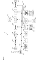
図1は、本発明の一実施の形態による電子カメラ1の構成例を説明するブロック図である。図1において、電子カメラ1は、撮影光学系11と、撮像素子12と、AFE(Analogfrontend)回路13と、画像処理回路14と、スピーカ駆動回路15と、スピーカ16と、LCDモニタ17と、RAM18と、フラッシュメモリ19と、CPU20と、メモリカードインターフェース(I/F)21と、通信制御回路22と、操作部材23と、姿勢センサ24と、音声処理回路25と、ステレオマイク26と、照明装置28と、電源回路29と、レンズ駆動回路30とを備える。
Hereinafter, embodiments for carrying out the present invention will be described with reference to the drawings.
FIG. 1 is a block diagram illustrating a configuration example of an electronic camera 1 according to an embodiment of the present invention. In FIG. 1, an electronic camera 1 includes an imaging optical system 11, an image sensor 12, an AFE (Analogfrontend) circuit 13, an image processing circuit 14, a speaker drive circuit 15, a speaker 16, an LCD monitor 17, and a RAM 18. A flash memory 19, a CPU 20, a memory card interface (I / F) 21, a communication control circuit 22, an operation member 23, an attitude sensor 24, an audio processing circuit 25, a stereo microphone 26, and a lighting device. 28, a power supply circuit 29, and a lens driving circuit 30.

CPU20、RAM18、フラッシュメモリ19、メモリカードインターフェース21、通信制御回路22、音声処理回路25、レンズ駆動回路30、画像処理回路14、照明装置28、スピーカ駆動回路15およびLCDモニタ17は、それぞれがバス27を介して接続されている。   The CPU 20, RAM 18, flash memory 19, memory card interface 21, communication control circuit 22, audio processing circuit 25, lens driving circuit 30, image processing circuit 14, lighting device 28, speaker driving circuit 15 and LCD monitor 17 are each a bus. 27 is connected.

撮影光学系11は、ズームレンズやフォーカシングレンズを含む複数のレンズ群で構成され、被写体像を撮像素子12の撮像面に結像させる。なお、図1を簡単にするため、撮影光学系11を単レンズとして図示している。   The photographic optical system 11 includes a plurality of lens groups including a zoom lens and a focusing lens, and forms a subject image on the imaging surface of the image sensor 12. In order to simplify FIG. 1, the photographing optical system 11 is shown as a single lens.

撮像素子12は、受光素子が撮像面に二次元配列されたCMOSイメージセンサなどによって構成される。撮像素子12は、撮影光学系11によって結像された被写体像を光電変換してアナログ画像信号を生成する。アナログ画像信号は、AFE回路13に入力される。   The imaging element 12 is configured by a CMOS image sensor or the like in which light receiving elements are two-dimensionally arranged on the imaging surface. The image sensor 12 photoelectrically converts the subject image formed by the photographing optical system 11 to generate an analog image signal. The analog image signal is input to the AFE circuit 13.

AFE回路13は、アナログ画像信号に対して相関二重サンプリングやゲイン調整などのアナログ処理を行うとともに、アナログ処理後の画像信号をデジタル画像データに変換する。デジタル画像データは画像処理回路14に入力される。画像処理回路14は、デジタル画像データに対して各種の画像処理(色補間処理、階調変換処理、輪郭強調処理、ホワイトバランス調整処理、画像圧縮処理、画像伸張処理など)を施す。   The AFE circuit 13 performs analog processing such as correlated double sampling and gain adjustment on the analog image signal, and converts the image signal after the analog processing into digital image data. The digital image data is input to the image processing circuit 14. The image processing circuit 14 performs various types of image processing (color interpolation processing, gradation conversion processing, contour enhancement processing, white balance adjustment processing, image compression processing, image expansion processing, etc.) on the digital image data.

スピーカ駆動回路15は、CPU20から送出された音声データに基づいて、たとえば操作音、注意音、音声メッセージなどの音声再生信号を生成する。スピーカ16は、音声再生信号に基づいて音声再生を行う。   The speaker drive circuit 15 generates a sound reproduction signal such as an operation sound, a caution sound, and a voice message based on the sound data sent from the CPU 20. The speaker 16 performs audio reproduction based on the audio reproduction signal.

LCDモニタ17は液晶パネルによって構成され、CPU20からの指示に応じて画像や操作メニュー画面などを表示する。RAM18はCPU20のワークメモリとして使用される。また、RAM18は、画像処理回路14による画像処理の前工程や後工程でのデジタル画像データを一時的に記憶する。フラッシュメモリ19は、CPU20に実行させるプログラムを記憶する他に、後述する参照用データを記憶する。   The LCD monitor 17 is composed of a liquid crystal panel, and displays an image, an operation menu screen, and the like according to an instruction from the CPU 20. The RAM 18 is used as a work memory for the CPU 20. The RAM 18 temporarily stores digital image data in the pre-process and post-process of image processing by the image processing circuit 14. The flash memory 19 stores reference data to be described later in addition to storing a program to be executed by the CPU 20.

CPU20は、フラッシュメモリ19が記憶するプログラムを実行することによって電
子カメラ1が行う動作を制御する撮影制御部である。CPU20は、AF(オートフォーカス)動作制御や、自動露出(AE)演算も行う。AF動作は、たとえば、スルー画像のコントラスト情報に基づいてフォーカシングレンズ(不図示)の合焦位置を求めるコントラスト検出方式を用いる。スルー画像は、撮影指示前に撮像素子12によって所定の時間間隔(たとえば30コマ/毎秒)で繰り返し取得されるモニタ用画像のことをいう。CPU20は、クロック信号に基づいて時刻を計時する計時機能も備える。
The CPU 20 is a photographing control unit that controls operations performed by the electronic camera 1 by executing a program stored in the flash memory 19. The CPU 20 also performs AF (autofocus) operation control and automatic exposure (AE) calculation. The AF operation uses, for example, a contrast detection method for obtaining a focus position of a focusing lens (not shown) based on contrast information of a through image. The through image refers to a monitor image that is repeatedly acquired by the image sensor 12 at a predetermined time interval (for example, 30 frames / second) before a shooting instruction. The CPU 20 also has a clocking function that clocks time based on the clock signal.

メモリカードインターフェース21はコネクタ(不図示)を有し、該コネクタにメモリカードなどの記憶媒体51が接続される。メモリカードインターフェース21は、接続された記憶媒体51に対するデータの書き込みや、記憶媒体51からのデータの読み込みを行う。記憶媒体51は、半導体メモリを内蔵したメモリカードなどで構成される。   The memory card interface 21 has a connector (not shown), and a storage medium 51 such as a memory card is connected to the connector. The memory card interface 21 writes data to the connected storage medium 51 and reads data from the storage medium 51. The storage medium 51 includes a memory card with a built-in semiconductor memory.

通信制御回路22は、CPU20からの指示に応じて外部機器との間での通信を制御する。通信制御回路22は、無線通信回路を備えており、アンテナ22aを介して電波を送受信する。本実施形態では、電子カメラ1と同様の構成を有する他の電子カメラ1との間で無線通信を行う例を説明する。なお、無線通信回路は、好適には、受信する信号の強度を測定したり、信号の送信範囲の制御を行うための回路、例えば、RSSI(Received Signal Strength Indicator)回路を備えている。   The communication control circuit 22 controls communication with an external device according to an instruction from the CPU 20. The communication control circuit 22 includes a wireless communication circuit, and transmits and receives radio waves via the antenna 22a. In the present embodiment, an example in which wireless communication is performed with another electronic camera 1 having the same configuration as the electronic camera 1 will be described. Note that the wireless communication circuit preferably includes a circuit for measuring the intensity of a received signal and controlling a transmission range of the signal, for example, a received signal strength indicator (RSSI) circuit.

通信制御回路22はさらに、CPU20からの指示に応じて人体を介して通信を行う人体通信機能を備える。具体的には、電子カメラ1の筐体の上下左右の面においてそれぞれ送受信用電極22b〜22eが露出するように配設される(図2)。電子カメラ1の使用者と、他の電子カメラ1の使用者とがそれぞれ少なくとも1つの送受信用電極に触れるように電子カメラ1を片手で把持し、両使用者が電子カメラ1を把持していない他方の手で互いに握手をすることにより、人体および人体間の容量結合によって形成される閉回路によって、両人体をアンテナとして電子カメラ1間の通信を行うものである(再表2006/054706号公報)。なお、通信制御部22は、CPU20からの指示に応じてケーブルを介して通信を行う有線通信機能を備えてもよい。この場合、不図示の有線LANポート等を有する。   The communication control circuit 22 further includes a human body communication function for performing communication via the human body in response to an instruction from the CPU 20. Specifically, the transmitting / receiving electrodes 22b to 22e are disposed so as to be exposed on the upper, lower, left and right surfaces of the casing of the electronic camera 1 (FIG. 2). The user of the electronic camera 1 and the user of the other electronic camera 1 hold the electronic camera 1 with one hand so that each user touches at least one transmission / reception electrode, and both users do not hold the electronic camera 1. By shaking hands with each other with the other hand, communication between the electronic cameras 1 is performed using both human bodies as antennas by a closed circuit formed by capacitive coupling between the human bodies (see Table 2006/054706). ). Note that the communication control unit 22 may have a wired communication function for performing communication via a cable in response to an instruction from the CPU 20. In this case, a wired LAN port (not shown) is provided.

操作部材23は、後述するレリーズボタン23a、ズームスイッチ23b 23c、十字スイッチ23g、メニュースイッチ23eなどを含む(図2)。操作部材23は、モード切替え操作やメニュー選択操作など、各操作に応じた操作信号をCPU20へ送出する。   The operation member 23 includes a release button 23a, a zoom switch 23b 23c, a cross switch 23g, a menu switch 23e, and the like which will be described later (FIG. 2). The operation member 23 sends an operation signal corresponding to each operation, such as a mode switching operation or a menu selection operation, to the CPU 20.

姿勢センサ24は、たとえば重力方向を検出し、検出信号をCPU20へ送出する。CPU20は、検出信号に基づいて電子カメラ1の姿勢を判定する。具体的には、電子カメラ1の縦位置、横位置だけでなく、上下逆さか否かも判定する。   The posture sensor 24 detects the direction of gravity, for example, and sends a detection signal to the CPU 20. The CPU 20 determines the attitude of the electronic camera 1 based on the detection signal. Specifically, it is determined whether the electronic camera 1 is upside down as well as the vertical and horizontal positions.

音声処理回路25は、マイク26で集音された音声信号を増幅し、増幅後の信号をA/D変換回路(不図示)によってデジタル音声データに変換する。照明装置28は、夜間の撮影時に被写体を照明するための装置である。電源回路29は、CPU20からの指示に応じて電池52による電圧を電子カメラ1内の各部へ供給するとともに、電池52の電圧を検出し、検出電圧を示す信号を電池残容量情報としてCPU20へ送出する。   The audio processing circuit 25 amplifies the audio signal collected by the microphone 26 and converts the amplified signal into digital audio data by an A / D conversion circuit (not shown). The illumination device 28 is a device for illuminating a subject during night photography. The power supply circuit 29 supplies the voltage from the battery 52 to each part in the electronic camera 1 in accordance with an instruction from the CPU 20, detects the voltage of the battery 52, and sends a signal indicating the detected voltage to the CPU 20 as remaining battery capacity information. To do.

レンズ駆動回路30は、撮影光学系11を構成するフォーカスレンズを光軸方向に進退移動させてピント調節するためのフォーカス調節用モータ(不図示)を駆動する回路と、撮影光学系11を構成するズームレンズを光軸方向に進退移動させて変倍比を調節するためのズーム調節用モータ(不図示)を駆動する回路とを含む。レンズ駆動回路30は、CPU20からの指示に応じてフォーカス調節用モータおよびズーム調節用モータをそれぞ
れ駆動する。
The lens driving circuit 30 constitutes the photographing optical system 11 and a circuit that drives a focus adjustment motor (not shown) for adjusting the focus by moving the focus lens constituting the photographing optical system 11 forward and backward in the optical axis direction. And a circuit for driving a zoom adjustment motor (not shown) for adjusting the zoom ratio by moving the zoom lens back and forth in the optical axis direction. The lens driving circuit 30 drives the focus adjustment motor and the zoom adjustment motor, respectively, in accordance with instructions from the CPU 20.

電子カメラ1のCPU20は、他の電子カメラ1(両者は同様の構成を有する)との間で通信を確立した状態で所定の協働処理を行う。電子カメラ1と他の電子カメラ1との間で通信が確立され、所定の協働処理が実行され得る状態を、以後、ペアリングとも呼ぶ。所定の協働処理が実行され得る状態とは、電子カメラ1と他の電子カメラ1との間で動作等にかかる指令を相互に送受信可能な状態である。また、協働処理としては、特に限定されるものではないが、例えば、電子カメラ1における動作と同一の動作を他の電子カメラ1に実行させたり、電子カメラ1における動作と異なる動作を他の電子カメラ1に実行させたり、他の電子カメラ1に画像データ等の情報を送信させたりする等が挙げられる。電子カメラ1のペアリングは、通常、電子カメラ1および他の電子カメラ1のうち一方から他方へコマンドおよびデータを送信し、これを受信した電子カメラ1がコマンド送信元の電子カメラ1へ返信して通信を確立後、後述する所定条件を満たすことによって成立する。なお、電子カメラ1と他の電子カメラ1との間での通信方式としては、例えば、有線通信、無線通信、人体通信等が挙げられる。また、これらの通信方式は、例えば、通信の確立までは人体通信とし、その後は無線通信とするなど、適宜組合せてもよい。   The CPU 20 of the electronic camera 1 performs a predetermined cooperative process in a state where communication is established with another electronic camera 1 (both having the same configuration). Hereinafter, a state in which communication is established between the electronic camera 1 and another electronic camera 1 and a predetermined cooperative process can be executed is also referred to as pairing. The state in which the predetermined cooperative process can be performed is a state in which commands relating to operations and the like can be transmitted and received between the electronic camera 1 and another electronic camera 1. In addition, the cooperative processing is not particularly limited, but for example, the same operation as that in the electronic camera 1 is executed by another electronic camera 1 or an operation different from the operation in the electronic camera 1 is performed. For example, it may be executed by the electronic camera 1 or information such as image data may be transmitted to another electronic camera 1. The pairing of the electronic camera 1 is usually performed by transmitting a command and data from one of the electronic camera 1 and the other electronic camera 1 to the other, and the electronic camera 1 that receives the command returns it to the electronic camera 1 that is the command transmission source. After establishing communication, it is established by satisfying a predetermined condition described later. Note that examples of the communication method between the electronic camera 1 and another electronic camera 1 include wired communication, wireless communication, and human body communication. Further, these communication methods may be appropriately combined, for example, human communication until the establishment of communication and wireless communication thereafter.

上記ペアリングを行うペアリングモードと、ペアリングを行わない通常モードとは切替え可能に構成される。このモード切替えは、たとえば、モードスイッチ23dの押下操作に応じて切替えてもよいし、メニュースイッチ23eの押下操作に応じて表示する「操作メニュー」画面の中で切替えを行うようにしてもよい。本説明では、ペアリングモードに切替えられている場合にCPU20が行う処理を中心に説明する。   The pairing mode in which the pairing is performed and the normal mode in which the pairing is not performed can be switched. This mode switching may be performed, for example, in accordance with the pressing operation of the mode switch 23d, or may be performed in an “operation menu” screen displayed in response to the pressing operation of the menu switch 23e. In this description, the processing performed by the CPU 20 when the mode is switched to the pairing mode will be mainly described.

<ペアリング成立条件>
ペアリング成立条件は、4つの条件の中から選択可能に構成される。ペアリング成立条件を選択する操作は、他の電子カメラ1との間で通信を行う前に、あらかじめ以下のように行われる。
<Pairing conditions>
The pairing establishment condition is configured to be selectable from four conditions. The operation for selecting the pairing establishment condition is performed in advance as follows before communication with another electronic camera 1 is performed.

図2は、電子カメラ1の背面図である。電子カメラ1の背面には、LCDモニタ17と、ズームスイッチ23b(T)と、ズームスイッチ23c(W)と、モードスイッチ23dと、メニュースイッチ23eと、削除スイッチ23fと、十字スイッチ23gと、OKスイッチ23hとが設けられている。また、電子カメラ1の筐体上面には上記送受信用電極22bが設けられる。また、筐体下面には上記送受信用電極22cが設けられる。そして、筐体右側面には上記送受信用電極22dが、筐体左側面には上記送受信用電極22dが、それぞれ設けられる。   FIG. 2 is a rear view of the electronic camera 1. On the back of the electronic camera 1, there are an LCD monitor 17, a zoom switch 23b (T), a zoom switch 23c (W), a mode switch 23d, a menu switch 23e, a deletion switch 23f, a cross switch 23g, and an OK. A switch 23h is provided. The transmission / reception electrode 22b is provided on the upper surface of the casing of the electronic camera 1. The transmission / reception electrode 22c is provided on the lower surface of the housing. The transmission / reception electrode 22d is provided on the right side of the casing, and the transmission / reception electrode 22d is provided on the left side of the casing.

CPU20は、メニュースイッチ23eが押下操作されると、図3に例示する「操作メニュー」画面をLCDモニタ17に表示させる。「操作メニュー」には、複数の選択項目、例えば、「登録撮影」項目171と、「ペアリング成立条件設定」項目172と、「ペアリングオフタイマー」項目173と、「ペアリング人物設定」項目174とが含まれる。CPU20は、「操作メニュー」画面を表示中に十字スイッチ23gが上下方向に押下操作されると、操作信号に応じて選択項目を上下に変更する。CPU20は、「ペアリング成立条件設定」項目172を選択した状態で十字スイッチ23gが決定方向(右決定)に押下操作されると、図4に例示する「ペアリング成立条件設定」画面をLCDモニタ17に表示させる。   When the menu switch 23 e is pressed, the CPU 20 displays an “operation menu” screen illustrated in FIG. 3 on the LCD monitor 17. The “operation menu” includes a plurality of selection items, for example, “registered photographing” item 171, “pairing establishment condition setting” item 172, “pairing off timer” item 173, and “pairing person setting” item. 174. When the cross switch 23g is pressed down while the “operation menu” screen is displayed, the CPU 20 changes the selection item up or down according to the operation signal. When the cross switch 23g is pressed in the determination direction (right determination) while the “pairing establishment condition setting” item 172 is selected, the CPU 20 displays the “pairing establishment condition setting” screen illustrated in FIG. 17 is displayed.

図4において、「ペアリング成立条件」として4つの選択項目、すなわち「通常」項目176と、「顔識別」項目177と、「握手」項目178と、「カメラタッチ」項目179とが表示される。CPU20は、図4に例示する画面を表示中に十字スイッチ23gが上下方向に押下操作されると、操作信号に応じて選択項目を上下に変更する。CPU20は、十字スイッチ23gが決定方向(右決定)に押下操作されると、その時点において選択している項目をペアリング成立条件として設定する。   In FIG. 4, four selection items, that is, a “normal” item 176, a “face identification” item 177, a “handshake” item 178, and a “camera touch” item 179 are displayed as the “pairing establishment condition”. . When the cross switch 23g is pressed down in the vertical direction while the screen illustrated in FIG. 4 is displayed, the CPU 20 changes the selection item up or down in accordance with the operation signal. When the cross switch 23g is pressed in the determination direction (right determination), the CPU 20 sets the item currently selected as a pairing establishment condition.

<通常>
ペアリング成立条件が「通常」に設定された場合、CPU20は、他の電子カメラ1との間の通信確立を条件にペアリングを成立させる。通信制御回路22は、所定範囲(たとえば、10m)で無線通信を行うようにあらかじめ送信電力が設定されている。なお、この送信電力は、CPU20からの指示によって段階的(たとえば、3m、50cm、3cm)に通信範囲を制限するように、あらかじめメニュー操作によって切替え可能に構成されている。
<Normal>
When the pairing establishment condition is set to “normal”, the CPU 20 establishes the pairing on the condition that communication with another electronic camera 1 is established. The communication control circuit 22 has transmission power set in advance so as to perform wireless communication within a predetermined range (for example, 10 m). The transmission power is configured to be switchable in advance by a menu operation so as to limit the communication range stepwise (for example, 3 m, 50 cm, 3 cm) according to an instruction from the CPU 20.

送信電力の切替えは、通信制御回路22における送信電力を切替える代わりに、通信制御回路22における送信電力を一定に保ったまま、通信制御回路22において受信の有無を判定する際の判定閾値を高低切替えるようにしてもよい。本実施の形態においては、いずれの場合も両電子カメラ1間は非接触である。   The switching of the transmission power is performed by switching the threshold value for determining whether or not there is reception in the communication control circuit 22 while keeping the transmission power in the communication control circuit 22 constant, instead of switching the transmission power in the communication control circuit 22. You may do it. In this embodiment, there is no contact between both electronic cameras 1 in any case.

<顔識別>
CPU20は、スルー画像に含まれる「顔」を検出し、その「顔」が所定人物の「顔」か否かを識別する機能を備える。本実施の形態においては、相手の「顔」を撮影するので、「顔」を識別する際の両電子カメラ1間は非接触である。顔検出処理および顔識別処理は、公知の技術であるため説明を省略する。ペアリング成立条件が「顔識別」に設定された場合、CPU20は、他の電子カメラ1との間の通信確立後、「顔識別」を条件にペアリングを成立させる。ペアリングを成立させる識別人物の設定操作は、他の電子カメラ1との間で通信を行う前に、あらかじめ以下のように行われる。
<Face identification>
The CPU 20 has a function of detecting a “face” included in the through image and identifying whether the “face” is a “face” of a predetermined person. In the present embodiment, since the “face” of the other party is photographed, there is no contact between the two electronic cameras 1 when identifying the “face”. Since the face detection process and the face identification process are well-known techniques, description thereof is omitted. When the pairing establishment condition is set to “face identification”, the CPU 20 establishes pairing on the condition of “face identification” after establishing communication with another electronic camera 1. The identification person setting operation for establishing the pairing is performed in advance as follows before communication with another electronic camera 1 is performed.

CPU20は、「操作メニュー」画面(図3)を表示中に「ペアリング人物設定」項目174を選択した状態で十字スイッチ23gが決定方向(右決定)に押下操作されると、図5に例示する「ペアリング人物設定」画面をLCDモニタ17に表示させる。CPU20は、フラッシュメモリ19内に記録(登録)されている全ての参照用データの中から「顔」のサムネイル画像データを読み出し、当該サムネイル画像を表示する。参照用データは、「顔」のサムネイル画像データと、当該画像データに基づいて生成された特徴量データとを含む。特徴量データは、上記「顔識別」に用いられる。「顔識別」に用いる参照用データは、あらかじめフラッシュメモリ19内に記録(登録)されている。登録手順については後述する。   When the cross switch 23g is pressed in the determination direction (right determination) while the “pairing person setting” item 174 is selected while the “operation menu” screen (FIG. 3) is displayed, the CPU 20 is illustrated in FIG. The “pairing person setting” screen is displayed on the LCD monitor 17. The CPU 20 reads the thumbnail image data of “face” from all the reference data recorded (registered) in the flash memory 19 and displays the thumbnail image. The reference data includes thumbnail image data of “face” and feature amount data generated based on the image data. The feature amount data is used for the “face identification”. The reference data used for “face identification” is recorded (registered) in the flash memory 19 in advance. The registration procedure will be described later.

図5において、人物A、人物B、および人物Cについての「顔」のサムネイル画像がそれぞれ表示されている。各サムネイル画像の左側には、それぞれチェックボックスが表示される。たとえば、サムネイル画像171の左側にはチェックボックス172が表示される。   In FIG. 5, thumbnail images of “faces” for person A, person B, and person C are displayed. A check box is displayed on the left side of each thumbnail image. For example, a check box 172 is displayed on the left side of the thumbnail image 171.

CPU20は、「ペアリング人物設定」画面を表示中に十字スイッチ23gが選択方向(上下方向)に押下操作されると、操作信号に応じてカーソル173の表示位置を上下に移動させる。CPU20は、OKスイッチ23hが押下操作された場合、カーソル173で囲まれているチェックボックス内にチェックマークを表示させる。CPU20は、チェックボックスにチェックマークを表示した状態でOKスイッチ23hが押下操作されると、当該チェックボックスのチェックマークを消す。CPU20は、「ペアリング人物設定」画面の中でチェックマークで示されるサムネイル画像の「顔」を、識別対象として設定する。   When the cross switch 23g is pressed in the selection direction (up and down direction) while the “pairing person setting” screen is displayed, the CPU 20 moves the display position of the cursor 173 up and down according to the operation signal. When the OK switch 23h is pressed, the CPU 20 displays a check mark in a check box surrounded by the cursor 173. When the OK switch 23h is pressed while the check mark is displayed in the check box, the CPU 20 deletes the check mark in the check box. The CPU 20 sets the “face” of the thumbnail image indicated by the check mark in the “pairing person setting” screen as an identification target.

<握手>
ペアリング成立条件が「握手」に設定された場合、CPU20は、他の電子カメラ1との間の通信確立後、上記人体通信によるデータ受信を条件にペアリングを成立させる。たとえば、上述したように通信確立した電子カメラ1および他の電子カメラ1の双方の使用者が握手(お互いの皮膚が触れればよい)をすると形成される閉回路により、電子カメラ1同士が所定のデータを送受してペアリングを成立させる。本実施の形態においては、握手の場合も両電子カメラ1間は非接触である。
<Handshake>
When the pairing establishment condition is set to “shake hands”, the CPU 20 establishes the pairing on the condition that the data reception by the human body communication is performed after establishing communication with the other electronic camera 1. For example, the electronic cameras 1 are connected to each other by a closed circuit formed when the users of both the electronic camera 1 and the other electronic camera 1 that have established communication as described above shake hands (simply touch each other's skin). Send and receive data to establish pairing. In the present embodiment, both electronic cameras 1 are not in contact with each other even when shaking hands.

<カメラタッチ>
ペアリング成立条件が「カメラタッチ」に設定された場合、CPU20は、他の電子カメラ1との間の通信確立後、両電子カメラ1間の直接接触を条件にペアリングを成立させる。上述したように、電子カメラ1の筐体の上下左右の面においてそれぞれ送受信用電極22b〜22eが露出するように配設されている(図2)。電子カメラ1同士がこれら送受信用電極22b〜22eのいずれかで直接接触する場合、人体を介する人体通信時に比べて閉回路のインピーダンスが低いために大きな電流が流れる。CPU20は、通信制御回路22を通してこの信号電流の発生を検知することにより、電子カメラ1相互の接触を判定する。なお、通信制御回路22は、送受信用電極22b〜22eのうちどの電極で接触したかを特定してCPU20へ知らせるように構成されている。
<Camera touch>
When the pairing establishment condition is set to “camera touch”, the CPU 20 establishes pairing on the condition of direct contact between the two electronic cameras 1 after establishing communication with the other electronic cameras 1. As described above, the transmission / reception electrodes 22b to 22e are disposed so as to be exposed on the upper, lower, left and right surfaces of the casing of the electronic camera 1 (FIG. 2). When the electronic cameras 1 are in direct contact with any of these transmission / reception electrodes 22b to 22e, a large current flows because the impedance of the closed circuit is lower than that during human body communication via the human body. The CPU 20 determines the contact between the electronic cameras 1 by detecting the generation of this signal current through the communication control circuit 22. The communication control circuit 22 is configured to identify which electrode of the transmission / reception electrodes 22b to 22e is in contact and notify the CPU 20 of the contact.

ペアリングモードに切替えられているCPU20がペアリングを成立させる処理の流れについて、図6に例示するフローチャートを参照して説明する。通信確立前の通信を無線通信で行う例である。電子カメラ1のCPU20および他の電子カメラ1のCPUは、ペアリングモードに切替えられると図6による処理を行うプログラムをそれぞれ起動させる。   The flow of processing for establishing the pairing by the CPU 20 that has been switched to the pairing mode will be described with reference to the flowchart illustrated in FIG. It is an example which performs communication before communication establishment by wireless communication. When the CPU 20 of the electronic camera 1 and the CPUs of the other electronic cameras 1 are switched to the pairing mode, the programs for performing the processing shown in FIG. 6 are started up.

図6のステップS11において、CPU20は、通信要求を行ってステップS12へ進む。たとえば、CPU20が通信制御回路22へ指示を送り、上記10m範囲に位置する他の電子カメラ1に届く送信電力で通信要求コマンドを送信させる。ステップS12において、CPU20は、通信要求に対する返信の有無を判定する。CPU20は、通信制御回路22で返信が受信された場合にステップS12を肯定判定してステップS13へ進む。CPU20は、返信が受信されない場合にはステップS12を否定判定してステップS17へ進む。   In step S11 of FIG. 6, the CPU 20 makes a communication request and proceeds to step S12. For example, the CPU 20 sends an instruction to the communication control circuit 22 to cause the communication request command to be transmitted with transmission power reaching the other electronic camera 1 located in the 10 m range. In step S12, the CPU 20 determines whether or not there is a reply to the communication request. When the reply is received by the communication control circuit 22, the CPU 20 makes a positive determination in step S12 and proceeds to step S13. If no reply is received, the CPU 20 makes a negative determination in step S12 and proceeds to step S17.

ステップS13において、CPU20は、ペアリング成立条件が「通常」か否かを判定する。CPU20は、ペアリング成立条件が「通常」に設定されている場合、ステップS13を肯定判定してステップS16へ進む。CPU20は、ペアリング成立条件が「通常」に設定されていない場合には、ステップS13を否定判定してステップS14へ進む。   In step S13, the CPU 20 determines whether or not the pairing establishment condition is “normal”. If the pairing establishment condition is set to “normal”, the CPU 20 makes a positive determination in step S13 and proceeds to step S16. If the pairing establishment condition is not set to “normal”, the CPU 20 makes a negative determination in step S13 and proceeds to step S14.

ステップS16において、CPU20は通信制御回路22へ指示を送り、他の電子カメラ1へ確認信号を送信させるとともに、送信先である他の電子カメラ1との間のペアリング成立回数を計数するカウンタを1つインクリメントさせてステップS27へ進む。確認信号は、ペアリングにおける「親機」が「子機」へ発する信号である。ここで、上記通信要求に通信要求側の識別情報(たとえば、電子カメラ1のID)を含め、上記返信に返信側の識別情報(他の電子カメラ1のID)を含めることにより、ペアリングの成立をIDごとに管理する。   In step S16, the CPU 20 sends an instruction to the communication control circuit 22, causes a confirmation signal to be transmitted to another electronic camera 1, and a counter that counts the number of times that pairing has been established with the other electronic camera 1 that is the transmission destination. Increment by one and go to step S27. The confirmation signal is a signal transmitted from the “master unit” to the “slave unit” in pairing. Here, the identification information of the communication request side (for example, the ID of the electronic camera 1) is included in the communication request, and the identification information of the return side (the ID of the other electronic camera 1) is included in the reply. The establishment is managed for each ID.

本実施形態では、「親機」と「子機」を以下のように決定する。ペアリング成立条件が「通常」に設定されている場合(ステップS13を肯定判定)は、最初に通信要求を送信(S11)した電子カメラ1をペアリングにおける「親機」とし、該通信要求に応じて返信(S18)した電子カメラ1をペアリングにおける「子機」とする。ペアリング成立条件が「顔認識」に設定されている場合(ステップS15を肯定判定)は、「顔識別」を行った方の電子カメラ1をペアリングにおける「親機」とし、「顔識別」された方の電子カメラ1をペアリングにおける「子機」とする。ペアリング成立条件が「握手」に設定されている場合(ステップS23を肯定判定)は、上記人体通信による閉回路を介して最初にコマンドおよびデータを送信した電子カメラ1をペアリングにおける「親機」とし、これを受信した電子カメラ1をペアリングにおける「子機」とする。「カメラタッチ」の場合の「親機」と「子機」の決定については後述する。   In the present embodiment, “master unit” and “slave unit” are determined as follows. When the pairing establishment condition is set to “normal” (Yes in step S13), the electronic camera 1 that first transmitted the communication request (S11) is set as the “master” in the pairing, and the communication request In response, the electronic camera 1 that has responded (S18) is set as a “slave unit” in pairing. When the pairing establishment condition is set to “face recognition” (Yes in step S15), the electronic camera 1 that has performed “face identification” is set as the “master” in pairing, and “face identification” The electronic camera 1 that has been used is referred to as a “slave” in pairing. When the pairing establishment condition is set to “shake handshake” (Yes in step S23), the electronic camera 1 that first transmitted the command and data via the closed circuit by the human body communication is set to “ The electronic camera 1 that has received this is referred to as a “slave unit” in pairing. The determination of “master unit” and “slave unit” in the case of “camera touch” will be described later.

ステップS27において、CPU20は、時刻合わせを行って図6による処理を終了する。時刻合わせは、たとえば、「親機」の時刻に「子機」の時刻を合わせることによって行う。具体的には、CPU20が通信制御回路22へ指示を送り、時刻情報を他の電子カメラ1へ送信させる。これにより、「親機」の時刻情報が「子機」へ伝えられて両者の時刻を揃えることができる。図6の処理の終了により、「親機」と「子機」との関係でペアリングが成立する。そして、時刻合わせのなされた「親機」と「子機」とは、ペアリング成立後、計時をそれぞれ開始する。CPU20は、ペアリング成立中において所定の処理を行う。ペアリング成立中の処理については後述する。   In step S27, the CPU 20 adjusts the time and ends the process of FIG. The time adjustment is performed, for example, by adjusting the time of the “child device” to the time of the “parent device”. Specifically, the CPU 20 sends an instruction to the communication control circuit 22 to transmit time information to another electronic camera 1. Thereby, the time information of the “master unit” is transmitted to the “slave unit”, and the time of both can be aligned. By completing the processing in FIG. 6, pairing is established by the relationship between the “master unit” and the “slave unit”. Then, the “master unit” and “slave unit” whose time has been set start timing after the pairing is established. The CPU 20 performs a predetermined process while pairing is established. The process during pairing establishment will be described later.

ステップS14において、CPU20は、ペアリング成立条件が「顔識別」か否かを判定する。CPU20は、ペアリング成立条件が「顔識別」に設定されている場合、ステップS14を肯定判定してステップS15へ進む。CPU20は、ペアリング成立条件が「顔識別」に設定されていない場合には、ステップS14を否定判定してステップS22へ進む。   In step S <b> 14, the CPU 20 determines whether the pairing establishment condition is “face identification”. When the pairing establishment condition is set to “face identification”, the CPU 20 makes a positive determination in step S14 and proceeds to step S15. If the pairing establishment condition is not set to “face identification”, the CPU 20 makes a negative determination in step S14 and proceeds to step S22.

ステップS15において、CPU20は、「顔識別」したか否かを判定する。CPU20は、登録されている顔を識別した場合にステップS15を肯定判定してステップS16へ進み、登録されている顔を識別しない場合にはステップS15を否定判定してステップS26へ進む。なお、CPU20は、「顔識別」に用いるスルー画像をLCDモニタ17にリアルタイムに再生表示させるとともに、「顔識別」した場合には、当該「顔」を示す表示(たとえば、「顔」を囲む枠など)をスルー画像に重ねて表示させる。CPU20は、複数の「顔」を識別した場合には、たとえば、1番大きい顔(スルー画像に占める割合が最大のもの)を選ぶ。   In step S15, the CPU 20 determines whether or not “face identification” has been performed. If the registered face is identified, the CPU 20 makes an affirmative decision in step S15 and proceeds to step S16. If the registered face is not identified, the CPU 20 makes a negative decision in step S15 and proceeds to step S26. The CPU 20 reproduces and displays the through image used for “face identification” on the LCD monitor 17 in real time. When “face identification” is performed, the CPU 20 displays the “face” (for example, a frame surrounding the “face”). Etc.) overlaid on the through image. When the CPU 20 identifies a plurality of “faces”, for example, the CPU 20 selects the largest face (having the largest ratio in the through image).

ステップS22において、CPU20は、ペアリング成立条件が「握手」か否かを判定する。CPU20は、ペアリング成立条件が「握手」に設定されている場合、ステップS22を肯定判定してステップS23へ進む。CPU20は、ペアリング成立条件が「握手」に設定されていない場合には、ステップS22を否定判定してステップS24へ進む。   In step S <b> 22, the CPU 20 determines whether the pairing establishment condition is “shake hands”. If the pairing establishment condition is set to “shake hands”, the CPU 20 makes a positive determination in step S22 and proceeds to step S23. If the pairing establishment condition is not set to “shake hands”, the CPU 20 makes a negative determination in step S22 and proceeds to step S24.

ステップS23において、CPU20は、通信制御回路22から人体通信にて所定のデータを受信したことを示す信号が送信されるとステップS23を肯定判定してステップS16へ進む。CPU20は、人体通信による所定のデータ受信を示す信号が通信制御回路22から送信されない場合には、ステップS23を否定判定してステップS26へ進む。なお、本実施形態では、人体通信の閉回路が形成されると、ペアリング成立可を示すデータを送るように構成されている。   In step S23, when a signal indicating that predetermined data has been received by human body communication is transmitted from the communication control circuit 22, the CPU 20 makes a positive determination in step S23 and proceeds to step S16. If the signal indicating reception of predetermined data by human body communication is not transmitted from the communication control circuit 22, the CPU 20 makes a negative determination in step S23 and proceeds to step S26. In this embodiment, when a closed circuit for human body communication is formed, data indicating that pairing can be established is transmitted.

ステップS24において、CPU20は、通信制御回路22から電子カメラ1相互の接触を示す信号を受信したか否かを判定する。CPU20は、通信制御回路22から電子カメラ1相互の接触を示す信号が入力されるとステップS24を肯定判定してステップS25へ進む。CPU20は、相互接触を示す信号が入力されない場合にはステップS24を否定判定してステップS26へ進む。   In step S <b> 24, the CPU 20 determines whether a signal indicating contact between the electronic cameras 1 is received from the communication control circuit 22. When a signal indicating contact between the electronic cameras 1 is input from the communication control circuit 22, the CPU 20 makes a positive determination in step S24 and proceeds to step S25. If a signal indicating mutual contact is not input, the CPU 20 makes a negative determination in step S24 and proceeds to step S26.

ステップS25において、CPU20は上側判定処理を行う。上側判定とは、電子カメラ1相互が接触した場合にどちらの電子カメラ1が上側に位置するかを判定するものであり、本実施形態では反重力方向に位置するものを「上」側とする。   In step S25, the CPU 20 performs an upper side determination process. The upper determination is to determine which electronic camera 1 is located on the upper side when the electronic cameras 1 are in contact with each other, and in this embodiment, the one located in the antigravity direction is defined as the “upper” side. .

CPU20は、姿勢センサ24からの検出信号に基づく重力方向、および通信制御回路22からの信号に基づく接触電極情報に基づいて、図7に例示する判定テーブルを参照して上側判定を行う。たとえば、電子カメラ1を縦位置(右側面を下方)に保持して、該右側面にて他の電子カメラ1の上面(正位置)をカメラタッチした場合を例に説明する。電子カメラ1のCPU20は、重力方向が送受信電極22d側であって、接触電極が該送受信電極22dであることから、「上」判定をする。本実施形態では、「上」判定した方をペアリングにおける「親機」とし、「下」判定した方をペアリングにおける「子機」とする。一方、上記電子カメラ1にカメラタッチされた他の電子カメラ1のCPUは、重力方向が送受信電極22c側(正位置)であって、接触電極が上面(該送受信電極22b)であることから、「下」判定をする。   Based on the gravity direction based on the detection signal from the attitude sensor 24 and the contact electrode information based on the signal from the communication control circuit 22, the CPU 20 performs the upper determination with reference to the determination table illustrated in FIG. For example, a case where the electronic camera 1 is held in a vertical position (right side is downward) and the upper surface (normal position) of another electronic camera 1 is touched with the right side will be described as an example. The CPU 20 of the electronic camera 1 determines “up” because the gravity direction is on the transmission / reception electrode 22d side and the contact electrode is the transmission / reception electrode 22d. In the present embodiment, the one determined as “up” is the “parent device” in pairing, and the one determined as “down” is the “child device” in pairing. On the other hand, the CPU of another electronic camera 1 touched by the electronic camera 1 has a gravitational direction on the transmission / reception electrode 22c side (normal position) and a contact electrode on the upper surface (the transmission / reception electrode 22b). Make “down” judgment.

「上」判定をした場合のCPU20は、ステップS25を肯定判定してステップS16へ進む。「上」判定をしなかったCPU20は、ステップS25を否定判定してステップS20へ進む。ステップS20へ進むのは、「子機」として「親機」からの確認信号を待ち受けるためである。   If the CPU 20 makes the “up” determination, it makes a positive determination in step S25 and proceeds to step S16. The CPU 20 that has not made the “up” determination makes a negative determination in step S25 and proceeds to step S20. The reason for proceeding to step S20 is to wait for a confirmation signal from the “master unit” as the “slave unit”.

ステップS26において、CPU20はタイムアウトか否かを判定する。CPU20は、所定のタイムアウト時間(たとえば、1分)を経過した場合にステップS26を肯定判定してステップS1へ戻り、上述した処理を繰り返す。CPU20は、上記タイムアウト時間を経過していない場合には、ステップS26を否定判定してステップS14へ戻り、上述した処理を繰り返す。   In step S26, the CPU 20 determines whether or not a timeout has occurred. When a predetermined timeout time (for example, 1 minute) has elapsed, the CPU 20 makes a positive determination in step S26, returns to step S1, and repeats the above-described processing. If the timeout time has not elapsed, the CPU 20 makes a negative determination in step S26, returns to step S14, and repeats the above-described processing.

ステップS12を否定判定して進むステップS17において、CPU20は、他の電子カメラ1からの通信要求の有無を判定する。CPU20は、通信制御回路22で通信要求コマンドが受信された場合にステップS17を肯定判定してステップS18へ進む。CPU20は、通信制御回路22で通信要求コマンドが受信されない場合には、ステップS17を否定判定してステップS11へ戻る。   In step S <b> 17 which proceeds after making a negative determination in step S <b> 12, the CPU 20 determines whether or not there is a communication request from another electronic camera 1. When the communication control circuit 22 receives a communication request command, the CPU 20 makes a positive determination in step S17 and proceeds to step S18. If the communication control circuit 22 does not receive a communication request command, the CPU 20 makes a negative determination in step S17 and returns to step S11.

ステップS18において、CPU20は、返信を行ってステップS19へ進む。たとえば、CPU20が通信制御回路22へ指示を送り、他の電子カメラ1へ向けて返信を行わせる。ステップS19において、CPU20は、接触を示す信号が受信されたか否かを判定する。CPU20は、通信制御回路22から電子カメラ1相互の接触を示す信号が入力されるとステップS19を肯定判定してステップS25へ進み、相互接触を示す信号が入力されない場合にはステップS19を否定判定してステップS20へ進む。   In step S18, the CPU 20 sends a reply and proceeds to step S19. For example, the CPU 20 sends an instruction to the communication control circuit 22 and makes a reply to another electronic camera 1. In step S19, the CPU 20 determines whether or not a signal indicating contact has been received. When a signal indicating contact between the electronic cameras 1 is input from the communication control circuit 22, the CPU 20 makes a positive determination in step S19 and proceeds to step S25. When a signal indicating mutual contact is not input, the CPU 20 determines negative in step S19. Then, the process proceeds to step S20.

ステップS20において、CPU20は、通信制御回路22で他の電子カメラ1からの確認信号を受信したか否かを判定する。CPU20は、確認信号が受信された場合にステップS20を肯定判定するとともに、ペアリングを成立させてステップS28へ進む。CPU20は、確認信号が受信されない場合はステップS20を否定判定してステップS21へ進む。   In step S <b> 20, the CPU 20 determines whether the communication control circuit 22 has received a confirmation signal from another electronic camera 1. When the confirmation signal is received, the CPU 20 makes an affirmative decision in step S20, establishes pairing, and proceeds to step S28. If the confirmation signal is not received, the CPU 20 makes a negative determination in step S20 and proceeds to step S21.

ステップS28において、CPU20は時刻合わせを行って図6による処理を終了する。時刻合わせは、「親機」から送信される時刻情報に時刻を合わせることによって行う。図6の処理の終了により、「子機」と「親機」との関係でペアリングが成立する。   In step S28, the CPU 20 adjusts the time and ends the process shown in FIG. The time adjustment is performed by adjusting the time to the time information transmitted from the “master unit”. By completing the processing in FIG. 6, pairing is established in the relationship between the “child device” and the “parent device”.

ステップS21において、CPU20はタイムアウトか否かを判定する。CPU20は、所定のタイムアウト時間(たとえば、1秒)を経過した場合にステップS21を肯定判定してステップS11へ戻り、上述した処理を繰り返す。CPU20は、上記タイムアウト時間を経過していない場合には、ステップS21を否定判定してステップS20へ戻り、上述した処理を繰り返す。   In step S21, the CPU 20 determines whether or not a timeout has occurred. When a predetermined timeout time (for example, 1 second) has elapsed, the CPU 20 makes a positive determination in step S21, returns to step S11, and repeats the above-described processing. When the time-out period has not elapsed, the CPU 20 makes a negative determination in step S21, returns to step S20, and repeats the above-described processing.

なお、ステップS16における確認信号の送信は、ペアリング成立条件が「握手」の場合には人体通信によって送信しても構わない。   Note that the transmission of the confirmation signal in step S16 may be performed by human body communication when the pairing establishment condition is “shake hands”.

以上説明したように成立したペアリングは、手動操作(たとえば、モードスイッチ23dの押下操作によるペアリングモード解除)によって終了する他、あらかじめ設定しておいたオフタイマーによって自動終了させる。また、記憶媒体51の空き容量が所定の空き容量より少ない場合、他の電子カメラ1側の記憶媒体51の空き容量が所定の空き容量より少ない旨の情報を通信によって取得した場合、電池52の残容量が所定の残容量より少ない場合、他の電子カメラ1側の電池52の残容量が所定の残容量より少ない旨の情報を通信によって取得した場合の少なくとも1つに該当する場合は、ペアリングを自動終了するようにしてもよいし、両電子カメラ1の記憶媒体51の空き容量や、電池52の残容量の少なくとも1つの情報に応じて、ペアリングモードの滞在時間やペアリングモードでの静止画の撮影枚数や画像モード(高画質、標準、エコノミーなどの記録画素数)および動画撮影時の撮影時間やフレームレートを設定するようにしてもよい。なお、電子カメラ1と他の電子カメラ1との距離が上記通信範囲外へ離れた場合にもペアリングを終了する。ペアリング終了する際のCPU20は、ペアリングを成立させた相手の識別情報(たとえば、電子カメラ1のID)、当該相手の電子カメラ1とのペアリング成立回数、および当該相手の電子カメラ1とのペアリング累積時間を、電子カメラ1のIDごとに関連づけてフラッシュメモリ19内に保存しておく。   The pairing established as described above is terminated by a manual operation (for example, cancellation of the pairing mode by depressing the mode switch 23d) or automatically terminated by a preset off timer. Further, when the free space of the storage medium 51 is smaller than the predetermined free space, when information indicating that the free space of the storage medium 51 on the other electronic camera 1 side is smaller than the predetermined free space is acquired by communication, If the remaining capacity is less than the predetermined remaining capacity, the pair of the battery 52 on the other electronic camera 1 side corresponds to at least one of the cases where information indicating that the remaining capacity is less than the predetermined remaining capacity is obtained by communication. The ring may be automatically terminated, or depending on at least one information of the free capacity of the storage medium 51 of both the electronic cameras 1 and the remaining capacity of the battery 52, the staying time in the pairing mode and the pairing mode The number of still images to be shot, the image mode (the number of recorded pixels such as high image quality, standard, economy, etc.), and the shooting time and frame rate for moving image shooting may be set. Note that pairing is also terminated when the distance between the electronic camera 1 and another electronic camera 1 is outside the communication range. When the pairing is completed, the CPU 20 identifies the other party's identification information (for example, the ID of the electronic camera 1), the number of times the pairing is established with the other party's electronic camera 1, and the other party's electronic camera 1. Is stored in the flash memory 19 in association with each ID of the electronic camera 1.

ここで、ペアリングオフタイマーの設定手順について図8を参照して説明する。CPU20は、「操作メニュー」画面(図3)を表示中に「ペアリングオフタイマー」項目173を選択した状態で十字スイッチ23gが決定方向(右方向)に押下操作されると、図8に例示する「ペアリングオフタイマー」設定画面をLCDモニタ17に表示させる。CPU20は、「ペアリングオフタイマー」設定画面を表示中に十字スイッチ23gが選択方向(上下方向)に押下操作されると、操作信号に応じて選択項目を上下に変更する。CPU20は、十字スイッチ23gが右方向に押下操作されると、その時点において選択している項目に決定する。   Here, the setting procedure of the pairing-off timer will be described with reference to FIG. When the cross switch 23g is pressed in the determination direction (right direction) while the “pairing off timer” item 173 is selected while the “operation menu” screen (FIG. 3) is displayed, the CPU 20 is illustrated in FIG. The “pairing off timer” setting screen is displayed on the LCD monitor 17. When the cross switch 23g is pressed in the selection direction (up and down direction) while the “pairing off timer” setting screen is displayed, the CPU 20 changes the selection item up or down according to the operation signal. When the cross switch 23g is pressed rightward, the CPU 20 determines the item selected at that time.

「オフ」項目71に決定した場合のCPU20は、ペアリングの終了を上記手動によるペアリング解除操作によって行う。「30分」項目72に決定されている場合のCPU20は、ペアリングの終了をペアリングモード解除操作、およびペアリング開始時から30分経過時のうち、いずれか早い方によって行う。ペアリング開始時は、ステップS27における時刻合わせ時点に相当する。また、「1時間」項目73に決定されている場合のCPU20は、ペアリングの終了をペアリングモード解除操作、およびペアリング開始時から1時間経過時のうち、いずれか早い方によって行う。   When the “off” item 71 is determined, the CPU 20 ends the pairing by the above-described manual pairing cancellation operation. When the “30 minutes” item 72 is determined, the CPU 20 performs the end of the pairing by the pairing mode canceling operation and when 30 minutes have elapsed from the start of the pairing, whichever comes first. The start of pairing corresponds to the time adjustment time in step S27. In addition, the CPU 20 in the case where the “1 hour” item 73 is determined performs the end of the pairing by the pairing mode canceling operation and when one hour has elapsed from the start of the pairing, whichever comes first.

<登録撮影処理>
「顔識別」に用いる参照用データをフラッシュメモリ19内に記録(登録)する処理について説明する。CPU20は、LCDモニタ17に表示中の「操作メニュー画面」(図3)において「登録撮影」項目171を選択した状態で十字スイッチ23gが右方向に押下操作されると、登録撮影処理を行うためのプログラムを起動する。
<Registered shooting process>
Processing for recording (registering) reference data used for “face identification” in the flash memory 19 will be described. When the cross switch 23g is pressed down in the right direction with the “Registered Shooting” item 171 selected on the “Operation Menu Screen” (FIG. 3) displayed on the LCD monitor 17, the CPU 20 performs registered shooting processing. Start the program.

登録撮影プログラムを起動したCPU20は、LCDモニタ17にアシスト枠Gを表示させる。図9は、LCDモニタ17の表示例を説明する図である。CPU20は、RAM18が記憶している直近のスルー画像データに基づく画像をLCDモニタ17に表示させるとともに、アシスト枠Gを表示中の画像に重ねて表示させる。撮影者は、登録しようとする被写体人物の顔がアシスト枠G内に収まるように電子カメラ1を構える。   The CPU 20 that has activated the registered photographing program displays an assist frame G on the LCD monitor 17. FIG. 9 is a diagram for explaining a display example of the LCD monitor 17. The CPU 20 displays an image based on the latest through image data stored in the RAM 18 on the LCD monitor 17 and displays the assist frame G so as to overlap the image being displayed. The photographer holds the electronic camera 1 so that the face of the subject person to be registered is within the assist frame G.

CPU20は、登録撮影処理を終了させる操作信号(たとえば、メニュースイッチ23eからの操作信号)を受けた場合には、アシスト枠Gの表示を終了させて登録撮影処理を終了する。一方、CPU20は、登録撮影処理を終了させる操作信号(たとえば、メニュースイッチ23eからの操作信号)を受けない場合には、レリーズスイッチがオンしたか否かを判定する。CPU20は、レリーズボタン23aが全押し操作された場合に撮影処理を行う。   When the CPU 20 receives an operation signal (for example, an operation signal from the menu switch 23e) for ending the registered shooting process, the CPU 20 ends the display of the assist frame G and ends the registered shooting process. On the other hand, when the CPU 20 does not receive an operation signal (for example, an operation signal from the menu switch 23e) for ending the registered photographing process, the CPU 20 determines whether or not the release switch is turned on. The CPU 20 performs a photographing process when the release button 23a is fully pressed.

そしてCPU20は、撮影処理で取得した画像データが顔識別に使えるか否かを判定する。CPU20は、画像データのうちアシスト枠G内に対応するデータに基づいて顔検出処理を行い、顔を検出した場合には当該顔が登録されている顔か否かを判定する。具体的には、検出した顔の領域の画像データと、フラッシュメモリ19内に登録されているサムネイル画像の「顔」に対応する参照用データとに基づいて顔識別処理を行うことにより、検出されている人物の顔と、参照用データに含まれている人物の顔とが同一人物のものであるか否かを識別する。   Then, the CPU 20 determines whether the image data acquired by the shooting process can be used for face identification. The CPU 20 performs face detection processing based on data corresponding to the assist frame G in the image data, and when a face is detected, the CPU 20 determines whether the face is a registered face. Specifically, it is detected by performing face identification processing based on the image data of the detected face area and the reference data corresponding to the “face” of the thumbnail image registered in the flash memory 19. The person's face and the person's face included in the reference data are identified as belonging to the same person.

CPU20は、既に登録されている顔の場合にはLCDモニタ17に、たとえば、「既に登録されています」と表示させる。登録されている顔でない場合には新たな人物の「顔」として参照用データをフラッシュメモリ19に記録(登録)する。具体的には、アシスト枠G内に対応する画像データに基づいてサムネイル画像データを生成し、上記画像データに基づいて特徴量データを生成する。そして、サムネイル画像データおよび特徴量データを含む参照用データをフラッシュメモリ19に記録する。これにより、ペアリング人物設定画面(図5)における人物Bのように、参照用データが登録される。   If the face is already registered, the CPU 20 causes the LCD monitor 17 to display, for example, “already registered”. If it is not a registered face, the reference data is recorded (registered) in the flash memory 19 as the “face” of the new person. Specifically, thumbnail image data is generated based on image data corresponding to the assist frame G, and feature amount data is generated based on the image data. Then, reference data including thumbnail image data and feature amount data is recorded in the flash memory 19. Thereby, the reference data is registered like the person B in the pairing person setting screen (FIG. 5).

<参照用データの削除>
フラッシュメモリ19に記録(登録)された参照用データは、以下のように削除可能である。LCDモニタ17にペアリング人物設定画面(図5)を表示した状態で削除スイッチ23fが押下操作されると、CPU20は、カーソル173で示される人物に関する参照用データを削除対象とする。
<Delete reference data>
The reference data recorded (registered) in the flash memory 19 can be deleted as follows. When the delete switch 23f is pressed while the pairing person setting screen (FIG. 5) is displayed on the LCD monitor 17, the CPU 20 sets the reference data related to the person indicated by the cursor 173 as a deletion target.

CPU20は、カーソル173で囲まれている人物Bについて、たとえば「人物Bのデータを削除しますか?」というメッセージをLCDモニタ17に表示する。CPU20は、再度削除スイッチ23fが押下操作されると、表示中のサムネイル画像データ、および対応する特徴量データを含む参照用データをフラッシュメモリ19から消去する。これにより、ペアリング人物設定画面(図5)から人物Bについての表示が削除される。   For example, the CPU 20 displays a message “Would you like to delete the data of the person B?” On the LCD monitor 17 for the person B surrounded by the cursor 173. When the delete switch 23 f is pressed again, the CPU 20 deletes the currently displayed thumbnail image data and the reference data including the corresponding feature amount data from the flash memory 19. Thereby, the display about the person B is deleted from the pairing person setting screen (FIG. 5).

<ペアリング成立中の処理>
1.画像閲覧
CPU20は、ペアリング成立中は、あらかじめ共有設定をしたファイルフォルダについて、その内容を相手側の電子カメラ1から無線通信(ペアリング成立条件が「握手」に設定されている場合は、無線通信または人体(上記「握手」などで形成された閉回路))を介して閲覧可能とする。本実施形態において閲覧は、ペアリング成立相手の電子カメラ1から受信した画像データによる再生画像をLCDモニタ17に再生表示することをいい、受信した画像データを電子カメラ1内の不揮発性メモリ(フラッシュメモリ19および記憶媒体51)へ記録保存することと異なる。共有設定は、たとえば、図3に例示した「操作メニュー」における設定項目に含めて行うことができる。
<Processing during pairing>
1. While viewing the pairing, the CPU 20 wirelessly communicates the contents of the file folder set in advance with the other electronic camera 1 (if the pairing establishment condition is set to “shake hands” It is possible to browse through communication or a human body (a closed circuit formed by the above-mentioned “handshake” or the like). In the present embodiment, browsing refers to reproducing and displaying a reproduction image based on image data received from the electronic camera 1 with which the pairing has been established on the LCD monitor 17, and the received image data is stored in a nonvolatile memory (flash memory) in the electronic camera 1. This is different from recording and saving in the memory 19 and the storage medium 51). For example, the sharing setting can be included in the setting items in the “operation menu” illustrated in FIG.

図10は、「親機」であるXさんの電子カメラ1のLCDモニタ17に表示された「フォルダ表示」画面の例である。図10において、自分(Xさん)のカメラ内のフォルダが表示されている。「自分のカメラ」側の「ペアフォルダ」は、ペアリング成立中にペアリングの相手(本例では「子機」であるBさんの電子カメラ1)に閲覧を許可するフォルダである。「自分のカメラ」側の「ペアフォルダ」内に記録されている画像ファイルは、確立している無線通信(ペアリング成立条件が「握手」に設定されている場合は、無線通信または人体通信)を介して「子機」であるBさんの電子カメラ1から閲覧できる。   FIG. 10 is an example of a “folder display” screen displayed on the LCD monitor 17 of the electronic camera 1 of Mr. X who is the “master”. In FIG. 10, a folder in the camera of the user (Mr. X) is displayed. The “pair folder” on the “my camera” side is a folder that permits browsing to the pairing partner (in this example, Mr. B's electronic camera 1 which is the “slave device”). The image file recorded in the “Pair Folder” on the “My Camera” side is the established wireless communication (when the pairing establishment condition is set to “shake hands”, wireless communication or human body communication) Can be viewed from the electronic camera 1 of Mr. B who is a “slave device”.

図10には、「子機」であるBさんの電子カメラ1内のフォルダも表示されている。「Bさんのカメラ」側の「ペアフォルダ」は、ペアリング成立中にペアリングの相手(本例では「親機」であるXさんの電子カメラ1)に閲覧を許可するフォルダである。   In FIG. 10, a folder in the electronic camera 1 of Mr. B who is a “slave” is also displayed. The “pair folder” on the “Mr. B's camera” side is a folder that allows browsing to the partner of pairing (in this example, Mr. X's electronic camera 1 which is “the parent”) during pairing establishment.

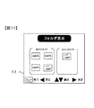
図11は、「子機」であるBさんの電子カメラ1のLCDモニタに表示された「フォルダ表示」画面の例である。図11において、自分(Bさん)のカメラ内のフォルダが表示されている。「自分のカメラ」側の「ペアフォルダ」は、ペアリング成立中にペアリングの相手(本例では「親機」であるXさんの電子カメラ1)に閲覧を許可するフォルダである。「自分のカメラ」側の「ペアフォルダ」内に記録されている画像ファイルは、確立している無線通信(ペアリング成立条件が「握手」に設定されている場合は、無線通信または人体通信)を介して「親機」であるXさんの電子カメラ1から閲覧できる。   FIG. 11 is an example of a “folder display” screen displayed on the LCD monitor of the electronic camera 1 of Mr. B who is the “child device”. In FIG. 11, a folder in the camera of the user (Mr. B) is displayed. The “pair folder” on the “your camera” side is a folder that permits browsing to the partner of pairing (in this example, Mr. X's electronic camera 1 which is the “master” in this example). The image file recorded in the “Pair Folder” on the “My Camera” side is the established wireless communication (when the pairing establishment condition is set to “shake hands”, wireless communication or human body communication) Can be viewed from the electronic camera 1 of Mr. X who is the “parent device”.

図11には、「親機」であるXさんの電子カメラ1内のフォルダも表示されている。「Xさんのカメラ」側の「ペアフォルダ」は、ペアリング成立中にペアリングの相手(本例では「子機」であるBさんの電子カメラ1)に閲覧を許可するフォルダである。   In FIG. 11, a folder in the electronic camera 1 of Mr. X who is the “parent device” is also displayed. The “pair folder” on the “Mr. X's camera” side is a folder that permits browsing to the other party of pairing (in this example, Mr. B's electronic camera 1 which is “slave device”).

ペアリング成立中の電子カメラ1は、「自分のカメラ」側の全てのフォルダと、ペアリングの相手である「○○さんのカメラ」側の「ペアフォルダ」とを閲覧できる。フォルダ選択操作(十字スイッチ23gの押下操作で選択、およびOKスイッチ23hの押下操作で決定)が行われた場合のCPU20は、選択決定したフォルダ内に記録されている画像ファイルによるサムネイル画像をLCDモニタ17に表示させる。   The paired electronic camera 1 can browse all the folders on the “own camera” side and the “pair folder” on the “XX's camera” side that is the partner of the pairing. When a folder selection operation (selected by pressing the cross switch 23g and determined by pressing the OK switch 23h) is performed, the CPU 20 displays a thumbnail image of the image file recorded in the selected folder on the LCD monitor. 17 is displayed.

図12は、サムネイル一覧表示例を示す図である。複数のサムネイルのうち1つにカーソル131が表示されている。カーソル位置は、サムネイル選択操作(十字スイッチ23gの押下操作)で上下左右に移動自在である。OKスイッチ23hが押下操作された場合、CPU20は、その時点でカーソルが位置するサムネイル画像に対応する再生画像をLCDモニタ17にフルスクリーン表示させる。   FIG. 12 is a diagram illustrating a thumbnail list display example. A cursor 131 is displayed on one of the plurality of thumbnails. The cursor position can be moved up and down and left and right by a thumbnail selection operation (operation of pressing the cross switch 23g). When the OK switch 23h is pressed, the CPU 20 causes the LCD monitor 17 to display a reproduction image corresponding to the thumbnail image at which the cursor is positioned at the full screen.

2.ペアリングのランクづけ
CPU20は、ペアリングを成立させた相手の情報(電子カメラ1の識別情報)にランク付けを行う。ランクは低い方から高い方へ、たとえばランク1〜ランク3の3段階に分ける。「親機」側のCPU20は、ペアリングを成立させた相手(本例では識別情報によって示される電子カメラ1)とのペアリング成立回数、およびペアリング累積時間に応じてランクを上げる。ランクを上げるか否かの判定に用いるペアリング成立回数およびペアリング累積時間は、あらかじめ電子カメラ1に対して設定され、設定内容がフラッシュメモリ19に保存されている。フラッシュメモリ19に記録保存されているペアリング成立回数やペアリング累積時間の設定変更は、たとえば、図3に例示した「操作メニュー」における設定項目に含めて行うことができる。
2. Ranking of Pairing The CPU 20 ranks the information (identification information of the electronic camera 1) of the partner who has established the pairing. The rank is divided into three levels of rank 1 to rank 3, for example, from the lowest to the highest. The CPU 20 on the “parent device” side raises the rank in accordance with the number of pairing establishments with the partner who established the pairing (in this example, the electronic camera 1 indicated by the identification information) and the accumulated pairing time. The number of pairing establishments and the accumulated pairing time used for determining whether or not to raise the rank are set in advance for the electronic camera 1, and the setting contents are stored in the flash memory 19. The setting change of the pairing establishment count and the pairing accumulated time recorded and stored in the flash memory 19 can be included in the setting items in the “operation menu” illustrated in FIG. 3, for example.

たとえば、ペアリング成立回数が20回を超える、およびペアリング累積時間が8時間を超える、のいずれかを達成した場合、「親機」側のCPU20はランク1からランク2へランクを変更し、変更内容をペアリング成立相手の識別情報に関連づけてフラッシュメモリ19に保存する。   For example, when the pairing establishment count exceeds 20 times and the accumulated pairing time exceeds 8 hours, the CPU 20 on the “master unit” side changes the rank from rank 1 to rank 2, The change contents are stored in the flash memory 19 in association with the identification information of the pairing partner.

CPU20はさらに、たとえば、ペアリング成立回数が50回を超える、およびペアリング累積時間が20時間を超える、のいずれかを達成した場合、「親機」側のCPU20はランク2からランク3へランクを変更し、変更内容をペアリング成立相手の識別情報に関連づけてフラッシュメモリ19に保存する。   Further, for example, when the CPU 20 achieves any of the pairing establishment count exceeding 50 times and the cumulative pairing time exceeding 20 hours, the CPU 20 on the “parent device” side ranks from rank 2 to rank 3 And the changed contents are stored in the flash memory 19 in association with the identification information of the pairing partner.

一般に、ペアリングの成立頻度が高い相手は、お互いをよく知った信頼できる相手や、家族や恋人など身近で親密度が高い人物であることが多い。ペアリング実績に応じてランクを分けるようにすることで、ペアリング相手を親密度に応じて自動的にグルーピングできる。   In general, a partner who has a high frequency of pairing is often a reliable partner who knows each other well, a family member or a lover who is familiar and highly familiar. By dividing the rank according to the pairing results, the pairing partners can be automatically grouped according to the intimacy.

3.ランクに応じた処理
CPU20は、ランク1である相手(本例では識別情報によって示される電子カメラ1)とペアリング成立中は、上述したように、あらかじめ共有設定をしたファイルフォルダについて、その内容を相手側の電子カメラ1から無線通信(ペアリング成立条件が「握手」に設定されている場合は、無線通信または人体通信)を介して閲覧可能とする。この場合、ペアリング成立中に撮影した撮影画像に限って閲覧可能とし、ペアリング非成立時に撮影した撮影画像については相手からの閲覧対象に含めない。
3. Processing according to the rank The CPU 20 determines the contents of the file folder that has been set in advance as described above while pairing is established with the other party of rank 1 (in this example, the electronic camera 1 indicated by the identification information). It is possible to browse from the electronic camera 1 on the other side via wireless communication (when the pairing establishment condition is set to “shake hands”, wireless communication or human body communication). In this case, it is possible to browse only the photographed image taken while the pairing is established, and the photographed image taken when the pairing is not established is not included in the viewing target from the partner.

CPU20はさらに、ランク2である相手(本例では識別情報によって示される電子カメラ1)とペアリング成立中は、あらかじめ共有設定をしたファイルフォルダに含まれるペアリング成立中に撮影した撮影画像だけでなく、当該共有設定をしたファイルフォルダに含まれるペアリング非成立時に撮影した撮影画像についても相手からの閲覧対象に含める。   In addition, the CPU 20 can only use the photographed image taken during the pairing establishment included in the file folder that is set in advance while the pairing is established with the other party of rank 2 (in this example, the electronic camera 1 indicated by the identification information). In addition, a captured image taken when pairing is not established included in the file folder with the sharing setting is also included in the viewing target from the other party.

そしてさらに、CPU20は、ランク3である相手(本例では識別情報によって示される電子カメラ1)とペアリング成立中は、あらかじめ共有設定をしたファイルフォルダに含まれる全画像について、閲覧だけでなくコピーも許可する。本実施形態においてコピーは、ペアリング成立相手の電子カメラ1側のファイルフォルダに含まれる撮影画像を複製し、自己の電子カメラ1側のファイルフォルダに記録保存することをいう。   Furthermore, the CPU 20 not only browses but also copies all the images included in the file folder that has been set in advance while pairing is established with the partner of rank 3 (in this example, the electronic camera 1 indicated by the identification information). Also allow. In the present embodiment, copying refers to copying a captured image included in the file folder on the electronic camera 1 side of the pairing establishment partner and recording and saving it in the file folder on the own electronic camera 1 side.

ペアリング成立相手ランク付けは、手動操作によってランクアップまたはランクダウンが可能に構成される。CPU20は、操作部材23からの操作信号によってランクアップまたはランクダウンを示す操作信号が入力された場合、操作信号に応じてランク1〜ランク3の範囲でランクの変更を行う。この場合にも、変更内容をペアリング成立相手の識別情報に関連づけてフラッシュメモリ19に保存するとともに、変更後のランクに応じて閲覧制限やコピー制限を行う。ランク情報は、「親機」から「子機」へ送信し、「親機」が管理する。   The pairing establishment opponent ranking is configured to be able to be ranked up or down by manual operation. When an operation signal indicating rank up or rank down is input by the operation signal from the operation member 23, the CPU 20 changes the rank in the range of ranks 1 to 3 according to the operation signal. Also in this case, the contents of the change are stored in the flash memory 19 in association with the identification information of the pairing partner, and browsing restrictions and copy restrictions are performed according to the rank after the change. The rank information is transmitted from the “master unit” to the “slave unit” and managed by the “master unit”.

上述したペアリング成立回数、およびペアリング累積時間に応じたランクの自動変更と手動操作によるランクの変更とが競合した場合は、手動操作による変更を優先させる。なお、CPU20は、操作部材23からの操作信号によってランクアップまたはランクダウンを示す操作信号が入力された場合、ペアリング成立相手側へランク変更要求を示す信号を送り、変更OKを示す信号が返信された場合に限りランク変更を行い、変更OKを示す信号が返信されない場合はランク変更を行わない。   If the automatic rank change according to the above-mentioned number of pairing establishments and the accumulated pairing time conflicts with the rank change by manual operation, priority is given to the change by manual operation. When an operation signal indicating rank up or rank down is input in response to an operation signal from the operation member 23, the CPU 20 sends a signal indicating a rank change request to the pairing partner, and a signal indicating change OK is returned. The rank is changed only when the rank is changed, and the rank is not changed when a signal indicating the change OK is not returned.

一方、ペアリング成立相手側からのランク変更要求を示す信号を受信したCPU20は、「ランク変更要求を受信しました。ランク変更してよいですか?」というメッセージをLCDモニタ17に表示させる。CPU20は、変更OKを示す操作信号が操作部材23から受信した場合に限り、ランク変更OKを示す信号をペアリング成立相手側へ送信する。   On the other hand, the CPU 20 that has received a signal indicating a rank change request from the other party on which the pairing has been established causes the LCD monitor 17 to display a message “Rank change request has been received. The CPU 20 transmits a signal indicating rank change OK to the pairing establishment partner side only when an operation signal indicating change OK is received from the operation member 23.

4.閲覧時のフィルタ処理
CPU20は、ランクの高低に応じて、閲覧時の表示解像度を変える。ペアリング成立した「親機」は、「子機」側に記録されている画像を「親機」側のLCDモニタに再生表示して閲覧させるとき、ランクによって異なるローパスフィルタ処理を行うことにより、ランクが低いほど低解像度閲覧、ランクが高いほど高解像度閲覧させるように表示解像度を変える。ペアリング成立した「子機」も同様に、「親機」側に記録されている画像を「子機」側のLCDモニタに再生表示して閲覧させるとき、ランクによって異なるローパスフィルタ処理を行うことにより、ランクが低いほど低解像度閲覧、ランクが高いほど高解像度閲覧させるように表示解像度を変える。
なお、閲覧時のフィルタ処理に関しては、そのほかに、無線通信回路により検出された電子カメラ1間での通信状態に応じてローパスフィルタ処理を行う。通信状態の例としては、電子カメラ1間での通信強度や、単位時間当たりの信号の伝送量が挙げられる。通信強度を例にすると、通信強度が低いほど低解像度閲覧、通信強度が高いほど高解像度閲覧させるように表示解像度を変える。ペアリング成立した「子機」も同様に、「親機」側に記録されている画像を「子機」側のLCDモニタに再生表示して閲覧させるとき、通信強度によって異なるローパスフィルタ処理を行うことにより、通信強度が低いほど低解像度閲覧、通信強度が高いほど高解像度閲覧させるように表示解像度を変える。このように構成すれば、LCDモニタに再生表示された画像の解像度によって、ユーザは、両電子カメラ1間の距離が近いのか、遠いのか、容易に判断が可能となる。
4). Filter processing during browsing The CPU 20 changes the display resolution during browsing according to the rank level. When the “parent” that has been paired is reproduced and displayed on the LCD monitor of the “parent” side, the low-pass filter process that differs depending on the rank is performed. The display resolution is changed so that the lower the rank, the lower the resolution, and the higher the rank, the higher the resolution. Similarly, when the “Slave unit” that has been paired is reproduced and displayed on the LCD monitor of the “Slave unit”, the low-pass filter processing that differs depending on the rank is performed. Thus, the display resolution is changed so that the lower the rank, the lower the resolution, and the higher the rank, the higher the resolution.
In addition, regarding the filtering process at the time of browsing, a low-pass filter process is performed according to the communication state between the electronic cameras 1 detected by the wireless communication circuit. Examples of the communication state include the communication intensity between the electronic cameras 1 and the signal transmission amount per unit time. Taking the communication strength as an example, the display resolution is changed such that the lower the communication strength, the lower the resolution viewing, and the higher the communication strength, the higher the resolution. Similarly, when the “slave unit” that has been paired is reproduced and displayed on the LCD monitor of the “slave unit” on the “slave unit” side, the low-pass filter process varies depending on the communication strength. Thus, the display resolution is changed such that the lower the communication strength is, the lower the resolution is, and the higher the communication strength is, the higher the resolution is. If comprised in this way, according to the resolution of the image reproduced | regenerated and displayed on the LCD monitor, a user can judge easily whether the distance between both the electronic cameras 1 is near or far.

5.撮影
ペアリング成立中は、「親機」側の電子カメラ1および「子機」側の電子カメラ1がそれぞれ単独で撮影処理を行う通常撮影と、「親機」側の電子カメラ1と「子機」側の電子カメラ1とを連携させて双方で撮影処理を行う連携撮影とを行うことができる。通常撮影を行うか、連携撮影を行うかの設定は、あらかじめ、図3に例示した「操作メニュー」における設定項目に含めて行うことができる。
5. While the pairing has been established, the normal camera in which the electronic camera 1 on the “main device” side and the electronic camera 1 on the “slave device” side each independently perform an imaging process, and the electronic camera 1 on the “main device” side and the It is possible to perform linked shooting in which the electronic camera 1 on the “machine” side is linked to perform shooting processing on both sides. The setting of whether to perform normal shooting or cooperative shooting can be included in advance in the setting items in the “operation menu” illustrated in FIG.

−通常撮影−
CPU20は、レリーズボタン23a(図2)の操作に基づいて撮影を行う。CPU20は、撮影処理前の情報および撮影処理で取得した画像データに基づいて、画像データおよび撮影情報を含むExif形式の画像ファイルを生成する。Exif形式の画像ファイルは、JPEG画像フォーマットの画像データ内にサムネイル画像や撮影情報などのデータを埋め込むようにしたものである。CPU20は、画像ファイルを記憶媒体51へ記録する。
-Normal shooting-
The CPU 20 performs shooting based on the operation of the release button 23a (FIG. 2). The CPU 20 generates an Exif format image file including the image data and the shooting information based on the information before the shooting process and the image data acquired in the shooting process. The Exif format image file is obtained by embedding data such as thumbnail images and shooting information in image data in the JPEG image format. The CPU 20 records the image file on the storage medium 51.

Exif形式の画像ファイルの構造は、画像の付属情報を記録するヘッダ領域と撮影画像データを記録する画像データ領域とを有する。CPU20は、画像ファイル内のヘッダ領域(タグ領域)に、ペアリング成立中に撮影した画像であることを示す情報を記録する。ペアリング成立中に撮影した画像であることを示す情報は、ペアリングの相手の識別情報および時刻合わせ後の計時に基づく撮影時刻情報を含む。   The structure of an Exif format image file has a header area for recording image auxiliary information and an image data area for recording captured image data. CPU20 records the information which shows that it is the image image | photographed during pairing establishment in the header area | region (tag area | region) in an image file. The information indicating that the image is taken while pairing is established includes identification information of the other party of pairing and shooting time information based on time keeping after time adjustment.

ペアリング成立中に撮影した画像であることを示す情報は、画像ファイルのヘッダ領域に記録する代わりに、画像ファイルに関連付けた別ファイルとして記録しても構わない。   Information indicating that the image was captured while pairing was established may be recorded as a separate file associated with the image file, instead of being recorded in the header area of the image file.

上記通常撮影の処理は、レリーズ操作された「親機」または「子機」がそれぞれ行う。ペアリング成立中に生成した画像ファイルは、あらかじめ共有設定をしたファイルフォルダ内に記録する。   The normal photographing process is performed by the “master” or “slave” that has been operated for release. The image file generated during pairing is recorded in a file folder that has been set in advance.

−連携撮影1−
ペアリング成立中において、「親機」側の電子カメラ1と「子機」側の電子カメラ1とが異なる撮影条件で撮影するように制御する。たとえば、「親機」のシャッター速度を「子機」のシャッター速度より速く制御する。連携撮影1を行う設定は、図3に例示した「操作メニュー」における設定項目に含めて行うことができる。
-Collaborative shooting 1-
While pairing is being established, control is performed so that the electronic camera 1 on the “master” side and the electronic camera 1 on the “slave” side shoot under different shooting conditions. For example, the shutter speed of the “master unit” is controlled to be faster than the shutter speed of the “slave unit”. Settings for performing linked shooting 1 can be included in the setting items in the “operation menu” illustrated in FIG.

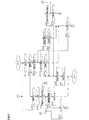
図17は、ペアリング成立中のCPU20が連携撮影1を行う場合に繰り返し実行する処理の流れを例示するフローチャートである。「親機」側の電子カメラ1と「子機」側の電子カメラ1の双方のCPU20がそれぞれ実行する。図17のステップS101において、CPU20は、ペアリングの相手の電子カメラ1から送信されるレリーズ信号を受信したか否かを判定する。レリーズ信号は、「親機」および「子機」のうちレリーズボタン23a(図2)が押下操作された電子カメラ1が他方の電子カメラ1へ撮影を指示する信号である。   FIG. 17 is a flowchart illustrating the flow of processing that is repeatedly executed when the CPU 20 that has established pairing performs cooperative shooting 1. The CPU 20 of each of the electronic camera 1 on the “parent device” side and the electronic camera 1 on the “child device” side executes. In step S101 in FIG. 17, the CPU 20 determines whether or not a release signal transmitted from the electronic camera 1 that is the other party of the pairing has been received. The release signal is a signal for instructing the other electronic camera 1 to take a picture when the release button 23a (FIG. 2) of the “master” and “slave” is pressed.

CPU20は、レリーズ信号を受信した場合にステップS101を肯定判定してステップS111へ進む。ステップS111〜ステップS115の処理は、ペアリング成立中に「親機」および「子機」のうちレリーズボタン23a(図2)が押下操作されなかった方の電子カメラ1のCPU20が行う処理に相当する。   When the release signal is received, the CPU 20 makes a positive determination in step S101 and proceeds to step S111. The processing in steps S111 to S115 corresponds to the processing performed by the CPU 20 of the electronic camera 1 in which the release button 23a (FIG. 2) is not pressed among “master” and “slave” during pairing establishment. To do.

CPU20は、レリーズ信号を受信しない場合にはステップS101を否定判定してステップS102へ進む。レリーズボタン23aが「親機」および「子機」のいずれかで操作されるまでは、双方の電子カメラ1のCPU20がそれぞれステップS101〜ステップS104の処理を繰り返す。   If the CPU 20 does not receive the release signal, the CPU 20 makes a negative determination in step S101 and proceeds to step S102. Until the release button 23a is operated by either “master” or “slave”, the CPUs 20 of both electronic cameras 1 repeat the processes of steps S101 to S104, respectively.

ステップS102において、CPU20は、構図ガイド機能がオンされているか否かを判定する。構図ガイドは、ペアリング成立中に「親機」および「子機」が共通の被写体を異なる撮影アングルで撮影するようにガイドを行う機能である。構図ガイドのオン/オフ設定は、あらかじめ、図3に例示した「操作メニュー」における設定項目に含めて行うことができる。   In step S102, the CPU 20 determines whether or not the composition guide function is turned on. The composition guide is a function that guides the “master” and “slave” to photograph a common subject at different photographing angles while pairing is established. The composition guide ON / OFF setting can be included in advance in the setting items in the “operation menu” illustrated in FIG.

CPU20は、構図ガイド機能がオン設定されている場合にステップS102を肯定判定してステップS103へ進み、構図ガイド機能がオン設定されていない場合にはステップS102を否定判定してステップS104へ進む。   If the composition guide function is set on, the CPU 20 makes an affirmative decision in step S102 and proceeds to step S103. If the composition guide function is not set on, the CPU 20 makes a negative decision in step S102 and proceeds to step S104.

ステップS103において、CPU20は構図ガイドを行う。図13および図15は、「親機」であるXさんの電子カメラ1のLCDモニタ17に表示されるスルー画像を例示する図である。図14および図16は、「子機」であるBさんの電子カメラ1のLCDモニタ17に表示されるスルー画像を例示する図である。   In step S103, the CPU 20 performs a composition guide. FIG. 13 and FIG. 15 are diagrams illustrating a through image displayed on the LCD monitor 17 of the electronic camera 1 of Mr. X who is the “parent device”. FIG. 14 and FIG. 16 are diagrams illustrating a through image displayed on the LCD monitor 17 of the electronic camera 1 of Mr. B who is a “slave device”.

「親機」および「子機」は、それぞれ自身で取得したスルー画像をLCDモニタ17に再生表示している。各CPU20は、スルー画像に基づいて「顔」検出処理を行い、「顔」を検出した場合には当該「顔」を示す枠をスルー画像に重ねて表示させる。CPU20は、「顔」領域のデータから得られる輪郭と目鼻の位置関係に基づいて、撮影方向を判定し、どちらへ動くべきかをLCDモニタ17上にガイド表示する。   Each of the “master unit” and “slave unit” reproduces and displays the through image acquired by itself on the LCD monitor 17. Each CPU 20 performs a “face” detection process based on the through image, and when “face” is detected, a frame indicating the “face” is displayed so as to overlap the through image. The CPU 20 determines the shooting direction based on the positional relationship between the contour and the eyes and nose obtained from the data of the “face” region, and displays a guide on the LCD monitor 17 as to which direction to move.

図13の場合、「親機」であるXさんが被写体人物の左へ回って電子カメラ1を構えるように促すべく、目安となる顔アイコンと矢印を点灯表示させ、さらにアングルガイド中であることを示す「アングルガイド」を点滅表示させる。図14の場合、「子機」であるBさんが被写体人物の右へ回って電子カメラ1を構えるように促すべく、目安となる顔アイコンと矢印を点灯表示させ、さらにアングルガイド中であることを示す「アングルガイド」を点滅表示させる。   In the case of FIG. 13, in order to prompt Mr. X who is the “main device” to turn to the left of the subject person and hold the electronic camera 1, a face icon and an arrow as a guide are lit and displayed and an angle guide is in progress. “Angle guide” indicating is blinking. In the case of FIG. 14, in order to encourage Mr. B who is a “slave unit” to turn to the right of the subject person and hold the electronic camera 1, a face icon and an arrow which are used as a guide are lit and displayed and an angle guide is being used. “Angle guide” indicating is blinking.

CPU20は、顔アイコンと目鼻の位置関係が合致したら、「OK」表示させて撮影を促す(図15、図16)。「OK」表示していない状態でも撮影は可能である。なお、顔アイコンや「アングルガイド」表示、「OK」表示が撮影画像に含まれるわけではない。   When the positional relationship between the face icon and the eyes and nose matches, the CPU 20 displays “OK” to prompt photographing (FIGS. 15 and 16). Shooting is possible even when “OK” is not displayed. Note that a face icon, “angle guide” display, and “OK” display are not included in the captured image.

ステップS104において、CPU20は、レリーズボタン23a(図2)が押下操作されたか否かを判定する。CPU20は、レリーズボタン23aの押下を示す操作信号が操作部材23から入力された場合にステップS104を肯定判定してステップS105へ進み、レリーズボタン23aの押下を示す操作信号が操作部材23から入力されない場合には、ステップS104を否定判定してステップS101へ戻る。ステップS101へ戻る場合は上述した処理を繰り返す。   In step S104, the CPU 20 determines whether or not the release button 23a (FIG. 2) has been pressed. When an operation signal indicating that the release button 23a is pressed is input from the operation member 23, the CPU 20 makes a positive determination in step S104 and proceeds to step S105, and an operation signal indicating that the release button 23a is pressed is not input from the operation member 23. In this case, a negative determination is made in step S104, and the process returns to step S101. When returning to step S101, the above-described processing is repeated.

ステップS105〜ステップS110の処理は、ペアリング成立中に「親機」および「子機」のうちレリーズボタン23aが押下操作された電子カメラ1のCPU20が行う処理である。   The processes in steps S105 to S110 are processes performed by the CPU 20 of the electronic camera 1 in which the release button 23a of the “master” and “slave” is pressed while pairing is established.

ステップS105において、CPU20は、所定の自動露出演算(AE)および自動焦点調節処理(AF)を行ってステップS106へ進む。ステップS106において、CPU20は通信制御回路22へ指示を送り、他方の電子カメラ1へレリーズ信号を送信させてステップS107へ進む。CPU20は、レリーズ信号とともに、露出演算結果を含む撮影条件(たとえば、シャッター速度、絞り値、感度、焦点距離、ホワイトバランス調整値、画質調整情報など)を示すデータを他方の電子カメラ1へ送信させる。   In step S105, the CPU 20 performs predetermined automatic exposure calculation (AE) and automatic focus adjustment processing (AF), and proceeds to step S106. In step S106, the CPU 20 sends an instruction to the communication control circuit 22, causes a release signal to be transmitted to the other electronic camera 1, and proceeds to step S107. The CPU 20 causes the other electronic camera 1 to transmit data indicating a shooting condition (for example, shutter speed, aperture value, sensitivity, focal length, white balance adjustment value, image quality adjustment information) including the exposure calculation result together with the release signal. .

画質調整情報は、どの画質調整アルゴリズムを適用するかを示す情報である。画質調整アルゴリズムとして、たとえば、「スタンダード」、「ニュートラル」、「ビビッド」、「モノクローム」をあらかじめ用意しておき、画像処理(ステップS108)において適用するアルゴリズムを示す。   The image quality adjustment information is information indicating which image quality adjustment algorithm is applied. As an image quality adjustment algorithm, for example, “standard”, “neutral”, “vivid”, and “monochrome” are prepared in advance, and an algorithm applied in image processing (step S108) is shown.

「スタンダード」は、標準的な画像に仕上げる画質調整アルゴリズムである。「ニュートラル」は、素材の自然な色あいを重視して仕上げる画質調整アルゴリズムである。「ビビッド」は、鮮やかな画像に仕上げる画質調整アルゴリズムである。具体的には、彩度を高めて赤色と緑色を鮮やかに加工するとともに、コントラストを高めてシャープな画像を得る。「モノクローム」は、白黒画像に仕上げる画質調整アルゴリズムである。   “Standard” is an image quality adjustment algorithm for finishing a standard image. “Neutral” is an image quality adjustment algorithm that finishes with emphasis on the natural color of the material. “Vivid” is an image quality adjustment algorithm that finishes a vivid image. Specifically, the saturation is increased and red and green are processed vividly, and the contrast is increased to obtain a sharp image. “Monochrome” is an image quality adjustment algorithm for finishing a monochrome image.

ステップS107において、CPU20は、撮像処理を行わせてステップS108へ進む。ステップS108において、CPU20は画像処理回路14に指示を送り、取得した画像データに対して所定の画像処理を行わせてステップS109へ進む。ステップS109において、CPU20は、画像処理後の画像データを含む画像ファイルを生成してステップS110へ進む。ステップS110において、CPU20はメモリカードインターフェース21へ指示を送り、画像ファイルを記憶媒体51に記録させて図17による処理を終了する。   In step S107, the CPU 20 performs an imaging process and proceeds to step S108. In step S108, the CPU 20 sends an instruction to the image processing circuit 14, performs predetermined image processing on the acquired image data, and proceeds to step S109. In step S109, the CPU 20 generates an image file including the image data after the image processing, and proceeds to step S110. In step S110, the CPU 20 sends an instruction to the memory card interface 21, causes the image file to be recorded in the storage medium 51, and ends the processing shown in FIG.

上述したステップS101を肯定判定した場合は、他方の電子カメラ1からのレリーズ信号に応じて撮影処理を行う。ステップS111において、CPU20は、所定の自動露出演算(AE)および自動焦点調節処理(AF)を行ってステップS112へ進む。この場合の自動露出演算(AE)では、レリーズボタン23aが押下操作された方の電子カメラ1から送信されている撮影条件を示すデータに基づいて、「親機」のシャッター速度を「子機」のシャッター速度より速くするように露光条件を異ならせる。たとえば、「親機」のシャッター速度が1/1000秒で、「子機」のシャッター速度が1/250秒とする。このため、CPU20は適正露出が得られるように絞り値または感度を変える。   When affirmative determination is made in step S101 described above, shooting processing is performed according to the release signal from the other electronic camera 1. In step S111, the CPU 20 performs predetermined automatic exposure calculation (AE) and automatic focus adjustment processing (AF), and proceeds to step S112. In the automatic exposure calculation (AE) in this case, the shutter speed of the “master unit” is set to “slave unit” based on the data indicating the shooting conditions transmitted from the electronic camera 1 on which the release button 23a is pressed. The exposure conditions are varied so as to be faster than the shutter speed. For example, the shutter speed of the “master unit” is 1/1000 seconds, and the shutter speed of the “slave unit” is 1/250 seconds. Therefore, the CPU 20 changes the aperture value or sensitivity so that proper exposure can be obtained.

ステップS112において、CPU20は、撮像処理を行わせてステップS113へ進む。ステップS113において、CPU20は画像処理回路14に指示を送り、取得した画像データに対して所定の画像処理を行わせてステップS114へ進む。レリーズボタン23aが押下操作された方の電子カメラ1から送信されている撮影条件を示すデータに基づいて、共通の画質調整アルゴリズムやホワイトバランス調整値を用いたり、異なる画質調整アルゴリズムやホワイトバランス調整値を用いたりすることができる。共通のアルゴリズムや調整値を使うか、あるいは異なるアルゴリズムや調整値を使うかは、あらかじめ、図3に例示した「操作メニュー」における設定項目に含めて行うことができる。   In step S112, the CPU 20 performs an imaging process and proceeds to step S113. In step S113, the CPU 20 sends an instruction to the image processing circuit 14, performs predetermined image processing on the acquired image data, and proceeds to step S114. Based on the data indicating the shooting conditions transmitted from the electronic camera 1 to which the release button 23a is pressed, a common image quality adjustment algorithm and white balance adjustment value are used, or different image quality adjustment algorithms and white balance adjustment values are used. Can be used. Whether to use a common algorithm or adjustment value or a different algorithm or adjustment value can be included in advance in the setting items in the “operation menu” illustrated in FIG.

ステップS114において、CPU20は、画像処理後の画像データを含む画像ファイルを生成してステップS115へ進む。ステップS115において、CPU20はメモリカードインターフェース21へ指示を送り、画像ファイルを記憶媒体51に記録させて図17による処理を終了する。   In step S114, the CPU 20 generates an image file including the image data after the image processing, and proceeds to step S115. In step S115, the CPU 20 sends an instruction to the memory card interface 21, causes the image file to be recorded in the storage medium 51, and ends the processing shown in FIG.

−連携撮影2−
ペアリング成立中において、「親機」側の電子カメラ1および「子機」側の電子カメラ1の一方が撮影中のときは、他方の電子カメラ1が待機し、撮影中の電子カメラ1の撮影が終了したら、待機中の電子カメラ1の撮影が可能になるように制御する。連携撮影2を行う設定は、図3に例示した「操作メニュー」における設定項目に含めて行うことができる。
-Collaborative shooting 2-
When one of the “main device” -side electronic camera 1 and the “slave device” -side electronic camera 1 is photographing while the pairing is being established, the other electronic camera 1 stands by and the electronic camera 1 being photographed When shooting is completed, control is performed so that the electronic camera 1 in standby can be shot. Settings for performing cooperative shooting 2 can be included in the setting items in the “operation menu” illustrated in FIG.

図18は、ペアリング成立中のCPU20が連携撮影2を行う場合に繰り返し実行する処理の流れを例示するフローチャートである。「親機」側の電子カメラ1と「子機」側の電子カメラ1の双方のCPU20がそれぞれ実行する。図18のステップS201において、CPU20は、ペアリングの相手の電子カメラ1から送信される撮像中信号を受信したか否かを判定する。撮像中信号は、「親機」および「子機」のうちレリーズボタン23a(図2)の押下操作に応じて撮像中の電子カメラ1が他方の電子カメラ1へ撮像中であることを知らせる信号である。   FIG. 18 is a flowchart illustrating the flow of processing that is repeatedly executed when the CPU 20 that has established pairing performs cooperative shooting 2. The CPU 20 of each of the electronic camera 1 on the “parent device” side and the electronic camera 1 on the “child device” side executes. In step S201 in FIG. 18, the CPU 20 determines whether or not an imaging signal transmitted from the paired partner electronic camera 1 has been received. The in-imaging signal is a signal that informs the other electronic camera 1 that the electronic camera 1 that is imaging is taking an image in response to the pressing operation of the release button 23a (FIG. 2) of the “master unit” and “slave unit”. It is.

CPU20は、撮像中信号を受信した場合にステップS201を肯定判定してステップS211へ進む。ステップS211およびステップS212の処理は、ペアリング成立中に「親機」および「子機」のうち待機する方の電子カメラ1のCPU20が行う処理に相当する。   When the CPU 20 receives the imaging signal, the CPU 20 makes a positive determination in step S201 and proceeds to step S211. The processing in step S211 and step S212 corresponds to the processing performed by the CPU 20 of the electronic camera 1 that is on standby among “master” and “slave” while pairing is established.

CPU20は、撮像中信号を受信しない場合にはステップS201を否定判定してステップS202へ進む。レリーズボタン23aが「親機」および「子機」のいずれかで操作されるまでは、双方の電子カメラ1のCPU20がそれぞれステップS201〜ステップS202の処理を繰り返す。   If the CPU 20 does not receive the imaging signal, the CPU 20 makes a negative determination in step S201 and proceeds to step S202. Until the release button 23a is operated by either “master” or “slave”, the CPUs 20 of both electronic cameras 1 repeat the processes of steps S201 to S202, respectively.

ステップS202において、CPU20は、レリーズボタン23a(図2)が押下操作されたか否かを判定する。CPU20は、レリーズボタン23aの押下を示す操作信号が操作部材23から入力された場合にステップS202を肯定判定してステップS203へ進み、レリーズボタン23aの押下を示す操作信号が操作部材23から入力されない場合には、ステップS202を否定判定してステップS201へ戻る。ステップS201へ戻る場合は上述した処理を繰り返す。   In step S202, the CPU 20 determines whether or not the release button 23a (FIG. 2) has been pressed. When the operation signal indicating that the release button 23a is pressed is input from the operation member 23, the CPU 20 makes a positive determination in step S202 and proceeds to step S203, and the operation signal indicating that the release button 23a is pressed is not input from the operation member 23. In this case, a negative determination is made in step S202, and the process returns to step S201. When returning to step S201, the above-described processing is repeated.

ステップS203〜ステップS210の処理は、ペアリング成立中に「親機」および「子機」のうちレリーズボタン23aが押下操作された電子カメラ1のCPU20が行う処理である。   The processes in steps S203 to S210 are processes performed by the CPU 20 of the electronic camera 1 in which the release button 23a of the “master” and “slave” is pressed while pairing is established.

ステップS203において、CPU20は通信制御回路22へ指示を送り、他方の電子カメラ1へ撮像中を示す信号を送信させてステップS204へ進む。ステップS204において、CPU20は、所定の自動露出演算(AE)および自動焦点調節処理(AF)を行ってステップS205へ進む。   In step S203, the CPU 20 sends an instruction to the communication control circuit 22, causes the other electronic camera 1 to transmit a signal indicating that imaging is in progress, and then proceeds to step S204. In step S204, the CPU 20 performs predetermined automatic exposure calculation (AE) and automatic focus adjustment processing (AF), and proceeds to step S205.

ステップS205において、CPU20は、撮像処理を行わせてステップS206へ進む。ステップS206において、CPU20は、レリーズボタン23a(図2)が押下操作されているか否かを判定する。CPU20は、レリーズボタン23aの押下を示す操作信号が操作部材23から継続して入力されている場合にステップS206を肯定判定してステップS204へ戻り、上述した処理を繰り返す(連写撮影)。   In step S205, the CPU 20 performs an imaging process and proceeds to step S206. In step S206, the CPU 20 determines whether or not the release button 23a (FIG. 2) is pressed. When the operation signal indicating the depression of the release button 23a is continuously input from the operation member 23, the CPU 20 makes a positive determination in step S206, returns to step S204, and repeats the above-described processing (continuous shooting).

CPU20は、レリーズボタン23aの押下を示す操作信号が操作部材23から入力されていない場合には、ステップS206を否定判定してステップS207へ進む。ステップS207において、CPU20は通信制御回路22へ指示を送り、他方の電子カメラ1へ撮像終了を示す信号を送信させてステップS208へ進む。   When the operation signal indicating that the release button 23a is pressed is not input from the operation member 23, the CPU 20 makes a negative determination in step S206 and proceeds to step S207. In step S207, the CPU 20 sends an instruction to the communication control circuit 22, causes the other electronic camera 1 to transmit a signal indicating the end of imaging, and proceeds to step S208.

ステップS208において、CPU20は画像処理回路14に指示を送り、取得した画像データに対して順番に所定の画像処理を行わせてステップS209へ進む。ステップS209において、CPU20は、画像処理後の画像データを含む画像ファイルを生成してステップS210へ進む。ステップS210において、CPU20はメモリカードインターフェース21へ指示を送り、画像ファイルを記憶媒体51に記録させて図18による処理を終了する。   In step S208, the CPU 20 sends an instruction to the image processing circuit 14, causes the acquired image data to be subjected to predetermined image processing in order, and proceeds to step S209. In step S209, the CPU 20 generates an image file including the image data after the image processing, and proceeds to step S210. In step S210, the CPU 20 sends an instruction to the memory card interface 21, causes the image file to be recorded in the storage medium 51, and ends the processing shown in FIG.

上述したステップS201を肯定判定した場合は、他方の電子カメラ1からの撮像終了を示す信号を受信するまで撮影処理を行わない。ステップS211において、CPU20は、ペアリングの相手の電子カメラ1から送信される撮像終了を示す信号を受信したか否かを判定する。CPU20は、撮像終了信号を受信した場合にステップS211を肯定判定してステップS212へ進む。CPU20は、撮像終了信号を受信しない場合にはステップS211を否定判定し、当該判定処理を繰り返しながら撮像終了信号を待つ。CPU20は、撮像終了信号を待っている間は、たとえば「待機中です」というメッセージをLCDモニタ17に表示させる。   When affirmative determination is made in step S201 described above, the imaging process is not performed until a signal indicating the end of imaging from the other electronic camera 1 is received. In step S <b> 211, the CPU 20 determines whether or not a signal indicating the end of imaging transmitted from the paired partner electronic camera 1 is received. When the CPU 20 receives the imaging end signal, the CPU 20 makes a positive determination in step S211 and proceeds to step S212. If the CPU 20 does not receive the imaging end signal, the CPU 20 makes a negative determination in step S211 and waits for the imaging end signal while repeating the determination process. While waiting for the imaging end signal, the CPU 20 displays, for example, a message “Waiting” on the LCD monitor 17.

ステップS212において、CPU20は、レリーズボタン23a(図2)が押下操作されたか否かを判定する。CPU20は、レリーズボタン23aの押下を示す操作信号が操作部材23から入力された場合にステップS212を肯定判定してステップS203へ進み、レリーズボタン23aの押下を示す操作信号が操作部材23から入力されない場合には、ステップS212を否定判定してステップS201へ戻る。ステップS201へ戻る場合は上述した処理を繰り返す。   In step S212, the CPU 20 determines whether or not the release button 23a (FIG. 2) has been pressed. When an operation signal indicating depression of the release button 23a is input from the operation member 23, the CPU 20 makes a positive determination in step S212 and proceeds to step S203, and an operation signal indicating depression of the release button 23a is not input from the operation member 23. In this case, a negative determination is made in step S212, and the process returns to step S201. When returning to step S201, the above-described processing is repeated.

−通常撮影−
ペアリング成立中において、「親機」側の電子カメラ1および「子機」側の電子カメラ1は、それぞれが単独で撮影可能に制御する。通常撮影を行う設定は、図3に例示した「操作メニュー」における設定項目に含めて行うことができる。
-Normal shooting-
While pairing is being established, the electronic camera 1 on the “master unit” side and the electronic camera 1 on the “slave unit” side are controlled so as to be capable of photographing independently. Settings for performing normal shooting can be included in the setting items in the “operation menu” illustrated in FIG.

図19は、ペアリング成立中のCPU20が通常撮影を行う場合に繰り返し実行する処理の流れを例示するフローチャートである。「親機」側の電子カメラ1と「子機」側の電子カメラ1の双方のCPU20が、それぞれ実行する。   FIG. 19 is a flowchart illustrating the flow of processing that is repeatedly executed when the CPU 20 that has established pairing performs normal shooting. The CPU 20 of both the electronic camera 1 on the “parent device” side and the electronic camera 1 on the “child device” side executes each.

図19のステップS301において、CPU20は、レリーズボタン23a(図2)が押下操作されたか否かを判定する。CPU20は、レリーズボタン23aの押下を示す操作信号が操作部材23から入力された場合にステップS301を肯定判定してステップS302へ進み、レリーズボタン23aの押下を示す操作信号が操作部材23から入力されない場合には、ステップS301を否定判定して当該処理を繰り返す。   In step S301 in FIG. 19, the CPU 20 determines whether or not the release button 23a (FIG. 2) has been pressed. When an operation signal indicating depression of the release button 23a is input from the operation member 23, the CPU 20 makes a positive determination in step S301 and proceeds to step S302, and an operation signal indicating depression of the release button 23a is not input from the operation member 23. In that case, a negative determination is made in step S301 and the process is repeated.

ステップS302において、CPU20は、所定の自動露出演算(AE)および自動焦点調節処理(AF)を行ってステップS303へ進む。ステップS303において、CPU20は、撮像処理を行わせてステップS304へ進む。ステップS304において、CPU20は画像処理回路14に指示を送り、取得した画像データに対して所定の画像処理を行わせてステップS305へ進む。ステップS305において、CPU20は、画像処理後の画像データを含む画像ファイルを生成してステップS306へ進む。ステップS306において、CPU20はメモリカードインターフェース21へ指示を送り、画像ファイルを記憶媒体51に記録させて図19による処理を終了する。   In step S302, the CPU 20 performs predetermined automatic exposure calculation (AE) and automatic focus adjustment processing (AF), and proceeds to step S303. In step S303, the CPU 20 performs an imaging process and proceeds to step S304. In step S304, the CPU 20 sends an instruction to the image processing circuit 14, performs predetermined image processing on the acquired image data, and proceeds to step S305. In step S305, the CPU 20 generates an image file including image data after image processing, and proceeds to step S306. In step S306, the CPU 20 sends an instruction to the memory card interface 21, causes the image file to be recorded in the storage medium 51, and ends the processing shown in FIG.

6.パスワードの共有
ペアリング成立中に「親機」および「子機」間でパスワードを共有してもよい。たとえば、ペアリング成立中に「親機」および「子機」のいずれか一方でパスワードを設定した場合、そのパスワード情報を他方の電子カメラ1へ送信し、「親機」および「子機」間でパスワードを共有する。パスワードの設定は、たとえば、メニュー画面において行う。
6). Password sharing The password may be shared between the “base unit” and “slave unit” while pairing is established. For example, if a password is set on one of the “base unit” and “slave unit” while pairing is established, the password information is transmitted to the other electronic camera 1 and between the “base unit” and “slave unit” Share your password with. The password is set on the menu screen, for example.

共有パスワードを設定した以降は、ペアリング成立中に「親機」および「子機」のいずれか一方で当該共有パスワードを入力して行った設定変更内容を、他方の電子カメラ1へ送信して該他方の電子カメラ1に反映させる。たとえば、上述した通常撮影を行うか、連携撮影を行うかの設定を「親機」側で行った場合、自動的に「子機」側にも適用させる。   After setting the shared password, the setting change made by inputting the shared password in one of the “master unit” and “slave unit” during pairing is sent to the other electronic camera 1 This is reflected in the other electronic camera 1. For example, if the above-described setting of whether to perform normal shooting or linked shooting is performed on the “parent device” side, it is automatically applied to the “child device” side.

共有パスワードを入力して行う設定変更項目には、上述したランクアップまたはランクダウン操作を含めてもよい。この場合には、操作部材23が操作された側の電子カメラ1からペアリング成立相手側の電子カメラ1へ上述したようなランク変更要求を示す信号を送ることなく、ランクアップまたはランクダウン後のランクを示す情報をペアリング成立相手側の電子カメラ1へ送る。   The setting change item performed by inputting the shared password may include the above-described rank up or rank down operation. In this case, the electronic camera 1 on the side on which the operation member 23 is operated does not send a signal indicating the rank change request as described above to the electronic camera 1 on the other side of the pairing establishment, and after rank up or down Information indicating the rank is sent to the electronic camera 1 on the partnering partner side.

ペアリング成立相手側から変更後のランクを示す情報を受信したCPU20は、受信情報に基づいてランクアップまたはランクダウンを行い、「ランク変更を行いました。」というメッセージをLCDモニタ17に表示させる。   The CPU 20 that has received the information indicating the changed rank from the partner who has completed pairing performs rank up or rank down based on the received information, and causes the LCD monitor 17 to display a message “Rank has been changed.” .

以上説明したようにパスワードを共有することで、「親機」および「子機」でそれぞれ同じ設定を行うことなく、一方から設定変更できるようになるので使い勝手を向上させることができる。   As described above, by sharing the password, it is possible to change the setting from one side without performing the same setting on each of the “base unit” and the “slave unit”, so that the usability can be improved.

以上説明した実施形態によれば、次の作用効果が得られる。
(1)電子カメラ1は、外部の電子カメラとの間で通信を行う通信制御回路22と、通信制御回路22を介して外部の電子カメラに対する指示を行うCPU20と、通信制御回路22を介して外部の電子カメラから指示を受付けるCPU20と、CPU20により指示する指示範囲およびCPU20により受付ける指示範囲の少なくとも一方を設定するCPU20とを備えるようにしたので、ペア状態に応じた内容でペア動作をさせることができる。
According to the embodiment described above, the following operational effects can be obtained.
(1) The electronic camera 1 includes a communication control circuit 22 that communicates with an external electronic camera, a CPU 20 that instructs the external electronic camera via the communication control circuit 22, and a communication control circuit 22. Since the CPU 20 that receives an instruction from the external electronic camera and the CPU 20 that sets at least one of the instruction range that is instructed by the CPU 20 and the instruction range that is received by the CPU 20 are provided, the pair operation is performed with the contents according to the pair state. Can do.

(2)通信制御回路22は、複数の外部の電子カメラと通信が可能であり、CPU20は、該CPU20により指示する指示範囲および該CPU20により受付ける指示範囲の少
なくとも一方が、通信制御回路22を介して通信を行う外部の電子カメラごとに異なるように設定するので、ペアとなる外部の電子カメラごとに異なる内容でペア動作をさせることができる。
(2) The communication control circuit 22 can communicate with a plurality of external electronic cameras, and the CPU 20 has at least one of an instruction range instructed by the CPU 20 and an instruction range accepted by the CPU 20 via the communication control circuit 22. Therefore, the pairing operation can be performed with different contents for each external electronic camera to be paired.

(3)通信制御回路22を介して通信を行った通信回数を外部の電子カメラごとに記録するフラッシュメモリ19、CPU20を備え、CPU20は、フラッシュメモリ19、CPU20により記録された通信回数に応じて外部機器に指示する指示範囲および受付ける指示範囲の少なくとも一方を設定するようにしたので、通信頻度に応じた内容でペア動作をさせることができる。 (3) The flash memory 19 and the CPU 20 that record the number of times of communication performed via the communication control circuit 22 for each external electronic camera are provided. The CPU 20 corresponds to the number of times of communication recorded by the flash memory 19 and the CPU 20. Since at least one of the instruction range to be instructed to the external device and the instruction range to be accepted is set, the pair operation can be performed with the content corresponding to the communication frequency.

(4)通信制御回路22を介して外部の電子カメラから受信した画像データに対して、CPU20により設定された画像処理(フィルタ処理)を行うCPU20と、CPU20により画像処理された画像データを表示するLCDモニタ17とを備え、指示範囲に応じたフィルタ処理を設定するので、画像データの送信元の外部の電子カメラごとに異なるフィルタ処理をさせることができる。 (4) The CPU 20 that performs image processing (filter processing) set by the CPU 20 on the image data received from the external electronic camera via the communication control circuit 22 and the image data image-processed by the CPU 20 are displayed. Since the LCD monitor 17 is provided and filter processing is set according to the designated range, different filter processing can be performed for each external electronic camera that is the transmission source of image data.

(5)フィルタ処理はぼかしを付加処理としたので、画像データの送信元の外部の電子カメラごとに異なるぼかし付加をさせることができる。 (5) Since the filtering process is an addition process of blurring, it is possible to add different blurring to each external electronic camera that is the transmission source of image data.

(6)電子カメラ1は、外部の電子カメラとの間で通信を行う通信制御回路22と、画像データを記憶媒体51に記録するメモリカードI/F21、CPU20と、画像データを表
示するLCDモニタ17と、通信制御回路22を介して通信を行う外部の電子カメラに応じて、該外部の電子カメラから取得される画像データについてのLCDモニタ17による再生表示の可否設定、該再生表示時の画像データに対するフィルタ処理の設定、および外部の電子カメラから取得される画像の記憶媒体51への記録の可否設定を設定するCPU20とを備えるようにした。これにより、再生表示の可否、該再生表示時のフィルタ処理、および外部の電子カメラから取得される画像の記録の可否について、通信相手の外部の電子カメラに応じて、それぞれ設定できる。
(6) The electronic camera 1 includes a communication control circuit 22 that communicates with an external electronic camera, a memory card I / F 21 that records image data in the storage medium 51, a CPU 20, and an LCD monitor that displays the image data. 17 and an external electronic camera that communicates with the communication control circuit 22 according to an external electronic camera, setting whether or not to reproduce the image data acquired from the external electronic camera on the LCD monitor 17, and an image at the time of the reproduction display The CPU 20 is configured to set a filter processing setting for data and a setting for whether or not an image acquired from an external electronic camera can be recorded in the storage medium 51. Accordingly, whether or not playback display is possible, filtering processing during playback display and whether or not an image acquired from an external electronic camera can be recorded can be set according to the external electronic camera of the communication partner.

以下、本発明に係るその他の実施形態を変形例として説明する。本発明は、上述の実施形態および下記の変形例に限定されるものではなく、上述の実施形態と以下の変形例とを組合せて構成されてもよいし、また、上述した実施形態の一部に代えて以下の変形例を採用して構成されてもよい。
(変形例1)
上述した図6の処理において、ステップS13(図6)を肯定判定した場合に、返信してきた(ステップS12)電子カメラ1の識別情報がフラッシュメモリ19内に保存されているか否かを調べるように構成してもよい。上述したように、CPU20は、ペアリング終了する際にペアリング成立相手を示す識別情報(たとえば、電子カメラ1のID)ごとに、ペアリング成立回数およびペアリング累積時間をフラッシュメモリ19内に保存している。そこで、この保存情報を参照することにより、返信してきた電子カメラ1の識別情報が保存されている場合には、ペアリング実績のある相手と判定してステップS16へ進み、ペアリングを成立させる。
Hereinafter, other embodiments according to the present invention will be described as modified examples. The present invention is not limited to the above-described embodiment and the following modified example, and may be configured by combining the above-described embodiment and the following modified example, or a part of the above-described embodiment. Instead of the above, the following modifications may be adopted.
(Modification 1)
In the processing of FIG. 6 described above, when an affirmative determination is made in step S13 (FIG. 6), it is checked whether or not the identification information of the electronic camera 1 returned (step S12) is stored in the flash memory 19. It may be configured. As described above, the CPU 20 stores, in the flash memory 19, the number of times that pairing has been established and the accumulated time of pairing for each piece of identification information (for example, the ID of the electronic camera 1) that indicates a pairing establishment partner when pairing is completed. doing. Therefore, by referring to the stored information, when the identification information of the electronic camera 1 that has returned is stored, it is determined that the other party has a pairing record, and the process proceeds to step S16 to establish pairing.

一方、返信してきた電子カメラ1の識別情報がフラッシュメモリ19内に保存されていない場合は、当該返信元の電子カメラ1に対して、返信元の電子カメラ1内に保存されているペアリング成立相手を示す識別情報を要求する。要求を受けた返信元の電子カメラ1が上記識別情報を含めて返信すると、この返信を受け取ったCPU20は、フラッシュメモリ19に保存されている識別情報と、返信に含まれる識別情報とを照合し、共通のペアリング相手が含まれているか否かを調べる。   On the other hand, if the identification information of the electronic camera 1 that has returned is not stored in the flash memory 19, the pairing that is stored in the electronic camera 1 that is the reply source is established for the electronic camera 1 that is the reply source. Requests identification information indicating the other party. When the electronic camera 1 of the reply source that received the request returns the response including the identification information, the CPU 20 that has received the response collates the identification information stored in the flash memory 19 with the identification information included in the reply. Check if a common pairing partner is included.

照合の結果、共通するペアリング相手が存在した場合のCPU20は、「友人の友人」である相手として判定し、「共通のペア相手がいます。新規ペアリングを行いますか?」というメッセージをLCDモニタ17に表示させる。CPU20は、「OK」操作を示す操作信号が操作部材23から入力された場合にペアリングを開始するべくステップS16へ進む。   If there is a common pairing partner as a result of the collation, the CPU 20 determines that the partner is a “friend of a friend” and displays a message “There is a common pair partner. Do you want to perform a new pairing?” It is displayed on the monitor 17. When the operation signal indicating the “OK” operation is input from the operation member 23, the CPU 20 proceeds to step S16 to start pairing.

上記メッセージをLCDモニタ17に表示させたものの「OK」操作を示す操作信号が操作部材23から入力されない場合、および上記照合の結果、共通するペアリング相手が存在しなかった場合のCPU20は、ペアリングを開始することなくステップS11へ戻る。以上説明した変形例1によれば、共通する友人を有する相手が所有する電子カメラ1との間のペアリングを促すことができる。   When the operation signal indicating the “OK” operation is not input from the operation member 23 although the message is displayed on the LCD monitor 17, and when there is no common pairing partner as a result of the verification, the CPU 20 The process returns to step S11 without starting the ring. According to the modified example 1 described above, pairing with the electronic camera 1 owned by a partner who has a common friend can be promoted.

(変形例2)
ペアリング成立中において、通信状態(通信距離)に応じて上述したペアリング時のランクをリアルタイムに変化させてもよい。「親機」側のCPU20は、受信信号レベルが通信距離に応じて変化することから、通信制御回路22における受信信号レベルに応じてランクを変化させる。メインCPU20は、ペアリング成立中であってランク3およびランク2の場合、それぞれ受信信号レベルが判定閾値より低下した場合にランクダウンさせる。この場合、変更内容をペアリング成立相手の識別情報に関連づけてフラッシュメモリ19に保存するとともに、変更後のランクに応じて閲覧制限やコピー制限を行う。ランク情報は、「親機」から「子機」へ送信し、「親機」が管理する。
(Modification 2)
During pairing establishment, the rank at the time of pairing described above may be changed in real time according to the communication state (communication distance). The CPU 20 on the “master” side changes the rank according to the received signal level in the communication control circuit 22 because the received signal level changes according to the communication distance. In the case of pairing being established and rank 3 and rank 2, the main CPU 20 ranks down when the received signal level falls below the determination threshold value. In this case, the change contents are stored in the flash memory 19 in association with the identification information of the pairing partner, and browsing restrictions and copy restrictions are performed according to the rank after the change. The rank information is transmitted from the “master unit” to the “slave unit” and managed by the “master unit”.

ペアリング時のランクをリアルタイムに変化させることで、ペアリング成立中に「親機」および「子機」間で行う画像閲覧時のローパスフィルタ処理がリアルタイムに変化する。このため、変形例2によれば、ペアリング成立相手側の電子カメラ1のファイルフォルダに含まれる撮影画像を自己の電子カメラ1に再生表示させて閲覧する場合に、自己の電子カメラ1のLCDモニタ17に再生表示される再生画像のぼけ具合が通信状態(通信距離)に応じて変化するので、ペアリング成立相手との距離を直感的につかむことができる。   By changing the rank at the time of pairing in real time, the low-pass filter processing at the time of image browsing performed between the “master unit” and the “slave unit” during the pairing is changed in real time. For this reason, according to the second modification, when the captured image included in the file folder of the electronic camera 1 on the other side of the pairing establishment is reproduced and displayed on the electronic camera 1, the LCD of the electronic camera 1 is displayed. Since the degree of blurring of the reproduced image reproduced and displayed on the monitor 17 changes according to the communication state (communication distance), it is possible to intuitively grasp the distance to the pairing partner.

(変形例3)
ペアリング成立中において、ペアリングの相手に閲覧許可(公開)する画像(自己側であらかじめ共有設定をしたファイルフォルダ内の画像)と、相手から閲覧許可された画像(相手側であらかじめ共有設定されたファイルフォルダ内の画像)との類似度に応じてペアリング時のランクを変化させてもよい。類似度の高低は、公知のパターンマッチング手法を用いて判定する。「親機」側のCPU20は、類似度が高いほどランクを上げ、類似度が低いほどランクを下げる。変更内容をペアリング成立相手の識別情報に関連づけてフラッシュメモリ19に保存するとともに、変更後のランクに応じて閲覧制限やコピー制限を行う点、ランク情報を「親機」から「子機」へ送信し、「親機」が管理する点は、上述した場合と同様である。
(Modification 3)
While pairing is in progress, images that are allowed to be viewed (published) to the other party of the pairing (images in a file folder that has been set in advance by the user) and images that have been permitted to be viewed by the other party (that is, the other party has been set in advance to share) The rank at the time of pairing may be changed according to the degree of similarity with the image in the file folder. The degree of similarity is determined using a known pattern matching method. The CPU 20 on the “parent device” side increases the rank as the similarity is higher, and lowers the rank as the similarity is lower. The content of the change is stored in the flash memory 19 in association with the identification information of the pairing partner, and the rank information is changed from “master unit” to “slave unit” in that browsing restriction and copy restriction are performed according to the changed rank. The point of transmission and management by the “base unit” is the same as in the case described above.

一般に、同じサークル等で活動する仲間同士や、行動を共にする友人は、同じような被写体を撮影する可能性が高い。撮影画像の類似度合いに応じてランクを分けるようにすることで、撮影に関して嗜好が近いペアリング相手を自動的にグルーピングできる。   In general, friends who are active in the same circle or friends who are acting together are likely to shoot similar subjects. By dividing the rank according to the degree of similarity of the captured images, it is possible to automatically group pairing partners with similar preferences regarding shooting.

(変形例4)
ペアリング成立中において、ペアリングの相手に閲覧許可(公開)する画像(自己側であらかじめ共有設定をしたファイルフォルダ内の画像)と、相手から閲覧許可された画像(相手側であらかじめ共有設定をしたファイルフォルダ内の画像)とで、撮影位置(GPS情報)を比較してペアリング時のランクを変化させてもよい。「親機」側のCPU20
は、撮影位置が近いほどランクを上げ、撮影位置が遠いほどランクを下げる。変更内容をペアリング成立相手の識別情報に関連づけてフラッシュメモリ19に保存するとともに、変更後のランクに応じて閲覧制限やコピー制限を行う点、ランク情報を「親機」から「子機」へ送信し、「親機」が管理する点は、上述した場合と同様である。
(Modification 4)
While pairing has been established, images that are allowed to be viewed (disclosed) by the pairing partner (images in a file folder that has been set in advance by the user) and images that have been permitted to be viewed by the partner (partner side that has been set in advance) The image in the file folder) and the shooting position (GPS information) may be compared to change the rank during pairing. CPU 20 on the “base unit” side
Increases the rank as the shooting position is closer, and lowers the rank as the shooting position is farther. The content of the change is stored in the flash memory 19 in association with the identification information of the pairing partner, and the rank information is changed from “master unit” to “slave unit” in that browsing restriction and copy restriction are performed according to the changed rank. The point of transmission and management by the “base unit” is the same as in the case described above.

一般に、同じサークル等で活動する仲間同士や、行動を共にする友人は、同じような場所で撮影する可能性が高い。撮影位置が合致する度合いに応じてランクを分けるようにすることで、撮影に関して嗜好が近いペアリング相手を自動的にグルーピングできる。   In general, friends who are active in the same circle or friends who are acting together are likely to shoot in the same place. By dividing the rank according to the degree to which the shooting positions match, pairing partners with similar preferences regarding shooting can be automatically grouped.

(変形例5)
ペアリング成立中において、ペアリングの相手に閲覧許可(公開)する画像(自己側であらかじめ共有設定をしたファイルフォルダ内の画像)と、相手から閲覧許可された画像(相手側であらかじめ共有設定をしたファイルフォルダ内の画像)とで、撮影条件を比較してペアリング時のランクを変化させてもよい。「親機」側のCPU20は、撮影条件が合致するほどランクを上げ、撮影条件が異なるほどランクを下げる。変更内容をペアリング成立相手の識別情報に関連づけてフラッシュメモリ19に保存するとともに、変更後のランクに応じて閲覧制限やコピー制限を行う点、ランク情報を「親機」から「子機」へ送信し、「親機」が管理する点は、上述した場合と同様である。
(Modification 5)
While pairing has been established, images that are allowed to be viewed (disclosed) by the pairing partner (images in a file folder that has been set in advance by the user) and images that have been permitted to be viewed by the partner (partner side that has been set in advance) The image in the file folder) and the shooting conditions may be compared to change the rank during pairing. The CPU 20 on the “parent device” side increases the rank as the shooting conditions are matched, and lowers the rank as the shooting conditions are different. The content of the change is stored in the flash memory 19 in association with the identification information of the pairing partner, and the rank information is changed from “master unit” to “slave unit” in that browsing restriction and copy restriction are performed according to the changed rank. The point of transmission and management by the “base unit” is the same as in the case described above.

一般に、同様の撮影条件で撮影する人は撮影に関して嗜好が近い可能性が高い。撮影条件が合致する度合いに応じてランクを分けるようにすることで、撮影に関して嗜好が近いペアリング相手を自動的にグルーピングできる。   In general, a person who shoots under the same shooting conditions is likely to have a close preference for shooting. By dividing the rank according to the degree to which the shooting conditions match, pairing partners with similar preferences regarding shooting can be automatically grouped.

(変形例6)
ペアリング成立条件によってランクを変化させてもよい。「親機」側のCPU20は、上述した「握手」によってペアリングを成立させた場合に、通常のランク(すなわち、フラッシュメモリ19に記録している管理情報であって、ペアリング成立回数およびペアリング累積時間に応じて決定されるランク)に比べて1段階ランクアップする。人体通信によってペアリング成立する場合は親密度が高いことが想定されるので、自動的にランクアップさせて使い勝手をよくする。このようにランクアップする場合も、変更内容をペアリング成立相手の識別情報に関連づけてフラッシュメモリ19に保存するとともに、変更後のランクに応じて閲覧制限やコピー制限を行う点、ランク情報を「親機」から「子機」へ送信し、「親機」が管理する点は、上述した場合と同様である。変形例6によれば、親密度が高いペアリング相手を自動的にグルーピングできる。
(Modification 6)
The rank may be changed according to the pairing establishment condition. When the pairing is established by the “handshake” described above, the CPU 20 on the “master unit” side is the normal rank (that is, the management information recorded in the flash memory 19, the number of pairing establishments and the pairing establishment number). Compared with the rank determined according to the ring accumulated time, the rank is increased by one level. When pairing is established by human body communication, it is assumed that the intimacy is high, so the rank is automatically raised to improve usability. Even in the case of ranking up in this way, the contents of the change are stored in the flash memory 19 in association with the identification information of the pairing partner, and the rank information is changed to “view restriction” or “copy restriction” according to the rank after the change. The point transmitted from the “master unit” to the “slave unit” and managed by the “master unit” is the same as described above. According to the modified example 6, pairing partners with high intimacy can be automatically grouped.

(変形例7)
ペアリング成立条件が「顔識別」である場合に、「顔識別」に用いたスルー画像から得られる笑顔度合いに応じてペアリング時のランクを変化させてもよい。「親機」側のCPU20は、「顔識別」に用いたスルー画像から得られる笑顔度合いが所定値より高い場合に、通常のランク(すなわち、フラッシュメモリ19に記録している管理情報であって、ペアリング成立回数およびペアリング累積時間に応じて決定されるランク)に比べて1段階ランクアップする。笑顔度合いが高い場合は親密度が高いことが想定されるので、自動的にランクアップさせて使い勝手をよくする。
(Modification 7)
When the pairing establishment condition is “face identification”, the rank at the time of pairing may be changed according to the smile degree obtained from the through image used for “face identification”. When the smile level obtained from the through image used for “face identification” is higher than a predetermined value, the CPU 20 on the “master” side is the normal rank (that is, the management information recorded in the flash memory 19). , The rank is determined according to the number of times the pairing is established and the pairing accumulated time). When the degree of smile is high, it is assumed that the closeness is high. Therefore, the rank is automatically raised to improve usability.

本実施形態では、笑顔度合いの判定を笑顔検出時に行う。CPU20は、スルー画像データのうち特定した人物の顔の領域に対応するデータに基づいて笑顔であるか否かを判定する。笑顔判定処理は、公知の技術であるため説明を省略する。CPU20はさらに、笑顔を判定した場合には当該笑顔についての笑顔レベルを判定する。笑顔レベルは、たとえば、2(大笑い)と、1(中笑い)と、0(微笑み)との3段階に分ける。CPU20は、笑顔レベルが2の場合に通常ランクより1段階ランクアップする。   In the present embodiment, the smile level is determined when a smile is detected. CPU20 determines whether it is a smile based on the data corresponding to the area | region of the specified person's face among through image data. Since the smile determination process is a known technique, a description thereof will be omitted. Further, when the CPU 20 determines a smile, the CPU 20 determines a smile level for the smile. The smile level is divided into three levels, for example, 2 (big laughter), 1 (medium laughter), and 0 (smile). When the smile level is 2, the CPU 20 moves up one rank from the normal rank.

(変形例8)
上述した連携撮影1において、「親機」の焦点距離を「子機」の焦点距離より長くするように撮影条件を異ならせてもよい。たとえば、「親機」の焦点距離が85mm相当の場合、「子機」の焦点距離を35mm相当とする。「親機」側の電子カメラ1および「子機」側の電子カメラ1による撮影画像がお互い似てしまうことが避けられる。そして、「ワイド」で撮影した方(本例では35mm相当)の電子カメラ1で用いるホワイトバランス調整値を、他方の電子カメラ1で用いるホワイトバランス調整値として用いるようにする。
(Modification 8)
In the cooperative shooting 1 described above, the shooting conditions may be varied so that the focal length of the “master unit” is longer than the focal length of the “slave unit”. For example, when the focal length of the “master unit” is 85 mm, the focal length of the “slave unit” is 35 mm. It is possible to avoid the images taken by the electronic camera 1 on the “parent device” side and the electronic camera 1 on the “child device” side from being similar to each other. Then, the white balance adjustment value used in the electronic camera 1 of the image taken in “wide” (corresponding to 35 mm in this example) is used as the white balance adjustment value used in the other electronic camera 1.

一般に、「ワイド」で撮影した方が「ズーム」で撮影した場合より撮影画面内の色情報が多いので、より適切なホワイトバランス調整値が得られる。このホワイトバランス調整値を「親機」および「子機」の双方で共通に用いることで、異なる調整値を用いる場合に比べて、両電子カメラ1で撮影された色合いを揃えることができる。このような制御は、同一被写体を略同一時刻で連携撮影するときに好適である。   In general, shooting with "Wide" has more color information in the shooting screen than shooting with "Zoom", so a more appropriate white balance adjustment value can be obtained. By using this white balance adjustment value in common for both the “master unit” and the “slave unit”, it is possible to align the colors photographed by the two electronic cameras 1 as compared to the case of using different adjustment values. Such control is suitable when cooperative shooting of the same subject is performed at approximately the same time.

また、「親機」と「子機」との間で異なる焦点距離に制御する場合は「親機」と「子機」との間で同じシャッター速度に揃えてもよい。撮像条件のこのような設定は、動いている同一被写体を略同一時刻で連携撮影するときに好適な設定である。例えば、被写体が止まっている画像または被写体が流れている画像のいずれかを同時に取得することができる。また、「親機」と「子機」との間で同じ焦点距離に制御する場合に「親機」と「子機」との間で異なる絞り値に制御してもよい。このような設定は、同一被写体を略同一時刻で連結撮影したときに好適な設定であり、例えば、ボケ感の異なる画像を同時に取得することができる。そのため、ユーザは撮影後に好みの画像を選択することができる。「親機」と「子機」との間で同じ焦点距離に制御する場合に「親機」と「子機」との間で異なるシャッター速度に設定してもよい。このような設定は、動いている同一被写体を略同一時刻で連携撮影するときに好適な設定である。例えば、被写体が止まっている画像と、被写体が流れている画像とを同時に取得することができる。上記は一例であり、撮影条件として「親機」と「子機」との間で任意に種々の組み合わせを行うようにしてもよい。撮影条件の例としては、上記のように、撮影光学系の変倍比、シャッター速度、絞り値、感度および色調整処理情報などが挙げられる。   Further, when controlling the focal length to be different between the “master unit” and the “slave unit”, the same shutter speed may be set between the “master unit” and the “slave unit”. Such a setting of the imaging condition is a preferable setting when cooperatively shooting the same moving subject at approximately the same time. For example, it is possible to simultaneously acquire either an image where the subject is stopped or an image where the subject is flowing. Further, when controlling the same focal length between the “master unit” and the “slave unit”, different aperture values may be controlled between the “master unit” and the “slave unit”. Such a setting is suitable when the same subject is linked and photographed at substantially the same time, and for example, images with different blurring feelings can be acquired simultaneously. Therefore, the user can select a favorite image after shooting. When controlling to the same focal length between the “master unit” and the “slave unit”, different shutter speeds may be set between the “master unit” and the “slave unit”. Such a setting is suitable when the same moving subject is photographed at approximately the same time. For example, it is possible to simultaneously acquire an image in which the subject is stopped and an image in which the subject is flowing. The above is an example, and various combinations may be arbitrarily performed between the “master unit” and the “slave unit” as imaging conditions. Examples of shooting conditions include the zoom ratio, shutter speed, aperture value, sensitivity, and color adjustment processing information of the shooting optical system as described above.

(変形例9)
上述した連携撮影2の説明では、レリーズボタン23aの押下操作が継続される間、連写撮影する例を説明した。この代わりに、レリーズボタン23aが押下操作されてから所定時間(たとえば10秒間)が経過するまで連写撮影してもよい。この場合のCPU20は、ステップ206(図18)において、ステップS202(またはS212)を肯定判定してからの経過時間が上記所定時間に達した場合に肯定判定させる。
(Modification 9)
In the description of the cooperative shooting 2 described above, an example in which continuous shooting is performed while the pressing operation of the release button 23a is continued has been described. Alternatively, continuous shooting may be performed until a predetermined time (for example, 10 seconds) elapses after the release button 23a is pressed. In this case, the CPU 20 makes an affirmative determination in step 206 (FIG. 18) when the elapsed time after the affirmative determination in step S202 (or S212) reaches the predetermined time.

(変形例10)
あるいは、レリーズボタン23aが押下操作されてからの連写撮影枚数が所定コマ(たとえば30コマ)に達するまで連写撮影してもよい。この場合のCPU20は、ステップ206において、ステップS202(またはS212)を肯定判定してからの連写コマ数が上記所定コマに達した場合に肯定判定させる。
(Modification 10)
Alternatively, continuous shooting may be performed until the number of continuous shots after the release button 23a is pressed down reaches a predetermined frame (for example, 30 frames). In this case, the CPU 20 makes an affirmative determination in step 206 when the number of continuously shot frames after the affirmative determination in step S202 (or S212) reaches the predetermined frame.

(変形例11)
上述した連写撮影画像を静止画像として記録する代わりに、動画ファイルを生成して記録する構成にしても構わない。また、一方の電子カメラ1が静止画像として記録し、他方の電子カメラ1が動画像として記録するようにしてもよい。
(Modification 11)
Instead of recording the above-described continuous shot image as a still image, a moving image file may be generated and recorded. Alternatively, one electronic camera 1 may record as a still image and the other electronic camera 1 may record as a moving image.

(変形例12)
一方の電子カメラ1で撮影中に、他方の電子カメラ1を撮影待機させるようにしたが、当該撮影待機中に録音させるように構成してもよい。この場合のCPU20は、ステップS201を肯定判定したらマイク26に録音のための集音を開始させ、ステップS211を肯定判定するまで集音を継続させる。
(Modification 12)
While the other electronic camera 1 is on standby for shooting while shooting with one electronic camera 1, it may be configured to record while waiting for shooting. In this case, if the CPU 20 makes a positive determination in step S201, the CPU 20 causes the microphone 26 to start collecting sound for recording, and continues sound collection until it makes a positive determination in step S211.

CPU20は音声処理回路25へ指示を送り、マイク26で集音された音声信号を逐次増幅、およびデジタル音声データに変換させる。CPU20は、音声ファイル内のヘッダ領域(タグ領域)に、ペアリング成立中に録音した音声であることを示す情報を含める。そして、メモリカードインターフェース21へ指示を送り、音声ファイルを記憶媒体51に記録させる。ペアリング成立中に録音した音声であることを示す情報は、ペアリングの相手の識別情報、録音および時刻合わせ後の計時に基づく録音時刻情報を含む。   The CPU 20 sends an instruction to the sound processing circuit 25 to sequentially amplify the sound signal collected by the microphone 26 and convert it into digital sound data. The CPU 20 includes, in the header area (tag area) in the audio file, information indicating that the audio is recorded during pairing establishment. Then, an instruction is sent to the memory card interface 21 to record the audio file in the storage medium 51. The information indicating that the voice is recorded while pairing is established includes identification information of the other party of pairing, recording time information based on recording and time keeping after time adjustment.

なお、ペアリング成立中に録音した音声であることを示す情報は、音声ファイルのヘッダ領域に記録する代わりに、音声ファイルに関連付けた別ファイルとして記録しても構わない。   Note that the information indicating that the voice is recorded while pairing is established may be recorded as a separate file associated with the voice file instead of being recorded in the header area of the voice file.

(変形例13)
上述した説明では、「カメラタッチ」の場合の「親機」と「子機」とを上下判定に基づいて決定するようにしたが、「親機」と「子機」とを左右判定に基づいて決定するようにしてもよい。この場合のCPU20は、ステップS25(図6)において、たとえば左側判定処理を行う。左側判定とは、電子カメラ1相互が接触した場合にどちらの電子カメラ1が左側に位置するかを判定するものであり、本変形例では電子カメラ1を背面側から見た場合に左手方向に位置するものを「左」側とする。
(Modification 13)
In the above description, “master unit” and “slave unit” in the case of “camera touch” are determined based on the up / down determination, but “master unit” and “slave unit” are determined based on the left / right determination. May be determined. In this case, the CPU 20 performs, for example, left side determination processing in step S25 (FIG. 6). The left side determination is to determine which electronic camera 1 is located on the left side when the electronic cameras 1 are in contact with each other. In this modification, the left side direction is obtained when the electronic camera 1 is viewed from the back side. The one located is the “left” side.

CPU20は、姿勢センサ24からの検出信号に基づく重力方向、および通信制御回路22からの信号に基づく接触電極情報に基づいて、図20に例示する判定テーブルを参照して左側判定を行う。たとえば、電子カメラ1を縦位置(右側面を下方)に保持して、レリーズボタン23aを有する面にて他の電子カメラ1の左側面(正位置)をカメラタッチした場合を例に説明する。電子カメラ1のCPU20は、重力方向が送受信電極22d側であって、接触電極が該送受信電極22bであることから、「左」判定をする。変形例13では、「左」判定した方をペアリングにおける「親機」とし、「右」判定した方をペアリングにおける「子機」とする。一方、上記電子カメラ1にカメラタッチされた他の電子カメラ1のCPUは、重力方向が送受信電極22c側(正位置)であって、接触電極が左側面(該送受信電極22e)であることから、「右」判定をする。   Based on the gravity direction based on the detection signal from the attitude sensor 24 and the contact electrode information based on the signal from the communication control circuit 22, the CPU 20 performs left side determination with reference to the determination table illustrated in FIG. For example, a case will be described as an example where the electronic camera 1 is held in the vertical position (the right side surface is downward) and the left side surface (normal position) of another electronic camera 1 is touched with the surface having the release button 23a. The CPU 20 of the electronic camera 1 determines “left” because the gravitational direction is on the transmission / reception electrode 22d side and the contact electrode is the transmission / reception electrode 22b. In the modified example 13, the one determined “left” is the “parent device” in pairing, and the one determined “right” is the “child device” in pairing. On the other hand, the CPU of the other electronic camera 1 touched by the electronic camera 1 has the gravitational direction on the transmission / reception electrode 22c side (normal position) and the contact electrode on the left side (the transmission / reception electrode 22e). , "Right" judgment.

「左」判定をした場合のCPU20は、ステップS25を肯定判定してステップS16へ進む。「左」判定をしなかったCPU20は、ステップS25を否定判定してステップS20へ進む。   If the CPU 20 makes the “left” determination, it makes a positive determination in step S25 and proceeds to step S16. The CPU 20 that has not determined “left” makes a negative determination in step S25 and proceeds to step S20.

(変形例14)
ペアリングにおける時刻合わせについて(図6のステップS27およびS28)、「親機」の時刻に「子機」の時刻を合わせる例を説明した。この代わりに、「親機」および「子機」の時刻のうち早い方に合わせたり、受信した標準電波に基づいて時刻補正する機能を備える方に合わせたりしてもよい。
(Modification 14)
Regarding the time adjustment in pairing (steps S27 and S28 in FIG. 6), an example in which the time of the “child device” is adjusted to the time of the “parent device” has been described. Instead, the time of the “master” and the “slave” may be set to the earlier time, or may be set to the one having the function of correcting the time based on the received standard radio wave.

(変形例15)
上述した説明において、CPU20は、記憶媒体51の空き容量が所定の空き容量より少ない場合、他の電子カメラ1側の記憶媒体51の空き容量が所定の空き容量より少ない旨の情報を通信によって取得した場合、電池52の残容量が所定の残容量より少ない場合、他の電子カメラ1側の電池52の残容量が所定の残容量より少ない旨の情報を通信によって取得した場合の少なくとも1つに該当する場合は、ペアリングを自動終了するようにした。これに加えて、CPU20は、ステップS11(図6)の処理を開始する前の時点で記憶媒体51の空き容量が所定の空き容量より少ない場合や、電池52の残容量が所定の残容量より少ない場合には、図6による処理を直ちに終了するとよい。
(Modification 15)
In the above description, when the free space of the storage medium 51 is smaller than the predetermined free space, the CPU 20 acquires information that the free space of the storage medium 51 on the other electronic camera 1 side is smaller than the predetermined free space by communication. If the remaining capacity of the battery 52 is smaller than the predetermined remaining capacity, the information indicating that the remaining capacity of the battery 52 on the other electronic camera 1 side is smaller than the predetermined remaining capacity is obtained by communication. When applicable, the pairing is automatically terminated. In addition to this, the CPU 20 determines that the remaining capacity of the storage medium 51 is less than the predetermined remaining capacity at the time before starting the process of step S11 (FIG. 6), or the remaining capacity of the battery 52 is less than the predetermined remaining capacity. If the number is small, the processing shown in FIG.

さらに、通信要求を受けた(ステップS17)CPU20は、返信(ステップS18)する前の時点で記憶媒体51の空き容量が所定の空き容量より少ない場合や、電池52の残容量が所定の残容量より少ない場合には、返信することなく図6による処理を終了するとよい。変形例15によれば、ペアリング成立中に記憶媒体51へ記録できなくなったり、ペアリング成立中に電池52が消耗して動作不能に陥ったりすることを避けることができる。   Further, the CPU 20 that has received the communication request (step S17) determines that the remaining capacity of the storage medium 51 is less than the predetermined remaining capacity at the time before the reply (step S18) or the remaining capacity of the battery 52 is the predetermined remaining capacity. If the number is smaller, the processing in FIG. 6 may be terminated without replying. According to the modified example 15, it is possible to avoid that recording to the storage medium 51 cannot be performed while the pairing is established, or that the battery 52 is consumed and cannot be operated while the pairing is established.

(変形例16)
上記実施形態では、ペアリングを成立させる外部機器をあらかじめ登録しておく一例として、外部機器を使用する人物の「顔」を登録する例を説明した。この代わりに、外部機器の名称等を登録するようにしてもよい。この場合は、「ペアリング人物設定」画面(図5)の代わりに「外部機器設定」画面をLCDモニタ17に表示させる。「外部機器設定」画面には、「顔」のサムネイル画像に代わる外部機器リストを表示させる。外部機器リストは、たとえば、各外部機器の名称や型番、IDなどを含む。
(Modification 16)
In the above embodiment, as an example of registering an external device that establishes pairing in advance, an example of registering a “face” of a person who uses the external device has been described. Instead, the name of the external device or the like may be registered. In this case, an “external device setting” screen is displayed on the LCD monitor 17 instead of the “pairing person setting” screen (FIG. 5). On the “external device setting” screen, an external device list replacing the thumbnail image of “face” is displayed. The external device list includes, for example, the name, model number, and ID of each external device.

CPU20は、図5と同様のチェックマークで示される外部機器をペアリング相手とすべき外部機器として設定する。そして、通信要求(ステップS11(図6))に応じて返信された情報に含まれるIDが、「外部機器設定」画面を用いて設定された外部機器のIDと一致することを条件として、ペアリングを成立させる。   The CPU 20 sets an external device indicated by a check mark similar to that in FIG. 5 as an external device to be paired with. Then, the pair included on the condition that the ID included in the information returned in response to the communication request (step S11 (FIG. 6)) matches the ID of the external device set using the “External Device Setting” screen. Establish the ring.

なお、この変形例では、通信要求(ステップS11)に応じて返信された情報に含まれるIDが「外部機器設定」画面を用いて設定された外部機器のIDと一致するか否かの判定を行う一例を説明したが、このステップは必要に応じて変形してもよい。例えば、通信制御回路22には常に電源が供給されるような回路構成にしておくことにより、「外部機器設定」で設定された外部機器から返信を検出できない場合に、CPU20は、当該外部機器が起動されていない、もしくは電源がオフであると判定し、通信制御回路22を介して当該外部機器を起動させる、もしくは電源をオンさせる信号を送信するようにしてもよい。そして、起動後の当該外部機器から返信された情報に基づき、当該外部機器が作動可能な状態にあるかを判定したうえで、作動可能な場合には、ペアリングを成立させる。外部機器が作動可能な状態にあるか否かの判定は、外部機器の筐体等に設けられた接触センサにより、ユーザによる筐体への接触が検知されたか否かや、ユーザによる外部機器への操作が検知されたか否かの情報を外部機器から受信して行う。なお、外部機器に設けられた送受信用電極22b〜22eを接触センサとして利用してもよい。
また、この通信要求(ステップS11)の変形例は、外部機器を使用する人物の「顔」を登録する例を説明した上記実施形態についても適用可能である。具体的には、CPU20は、ユーザが登録撮影されている顔をLCDモニタ17で認識し、例えばOKスイッチ23hを押下したときに、通信制御回路22を介して相手の電子カメラの電源をオンするようにすればよい。また、CPU20は、図5で示したように、ペアリング人物設定画面においてチェックボックスをチェックした人物が所有している電子カメラ1を通信制御回路22を介して起動させるようにしてもよい。この場合、チェックボックスをチェックした人物が近くにいるかどうかは不明な場合もあるので、通信距離を10〜100m以内に設定して通信するようにすればよい。
なお、電子カメラ1に被写界を認識するファインダーが備えられている場合には、LCDモニタ17で顔識別するのに代えて、このファインダーにより顔識別するようにしてもよい。
ペアリング要求により相手の電子カメラ1の電源を起動させるには、上述の顔識別に限定されるものではなく、人体通信やカメラタッチの際にも適用することができる。この場合、単なる握手やペアリング要求ではないカメラタッチと識別するために、OKスイッチ23hを利用するようにしてもよいし、握手の時間が所定時間、例えば、3秒以上続いたり、カメラタッチが所定時間、例えば、3秒以上続いたりした場合に通信制御回路22を介して相手の電子カメラ1の電源をオンにするようにしてもよい。なお、この場合、電子カメラ1の電源がオンの状態であっても、オフの状態であっても構わない。電子カメラ1および他の電子カメラ1が、主電源がオフの状態であっても通信制御回路22に電源が供給されるよう構成されておれば、電子カメラ1は、通信制御回路22により人体通信またはカメラタッチが検知された場合には、主電源をオンにして電子カメラ1を構成する各部を起動させることができる。
In this modification, it is determined whether or not the ID included in the information returned in response to the communication request (step S11) matches the ID of the external device set using the “external device setting” screen. Although an example of performing is described, this step may be modified as necessary. For example, when the communication control circuit 22 is configured so that power is always supplied, and when a reply cannot be detected from the external device set in the “external device setting”, the CPU 20 It may be determined that the device is not started or the power is off, and a signal for starting the external device or turning on the power may be transmitted via the communication control circuit 22. Then, based on the information returned from the external device after activation, it is determined whether the external device is in an operable state, and if it is operable, pairing is established. Whether or not the external device is in an operable state is determined based on whether or not the user has detected contact with the housing by a contact sensor provided in the housing or the like of the external device. Information on whether or not an operation is detected is received from an external device. In addition, you may utilize the electrodes 22b-22e for transmission / reception provided in the external apparatus as a contact sensor.
Further, the modified example of the communication request (step S11) can be applied to the above-described embodiment that describes an example of registering a “face” of a person who uses an external device. Specifically, the CPU 20 recognizes the face on which the user is registered and photographed on the LCD monitor 17, and turns on the power of the partner electronic camera via the communication control circuit 22 when, for example, the OK switch 23 h is pressed. What should I do? Further, as shown in FIG. 5, the CPU 20 may activate the electronic camera 1 owned by the person whose check box is checked on the pairing person setting screen via the communication control circuit 22. In this case, since it may be unknown whether the person who checked the check box is nearby, the communication distance may be set within 10 to 100 m.
When the electronic camera 1 is provided with a finder for recognizing the object scene, the face may be identified by this finder instead of the face identification by the LCD monitor 17.
Starting the power supply of the partner electronic camera 1 in response to a pairing request is not limited to the above-described face identification, but can also be applied to human body communication or camera touch. In this case, an OK switch 23h may be used to identify a camera touch that is not a simple handshake or pairing request, or the handshake time may continue for a predetermined time, for example, 3 seconds or more. The power supply of the partner electronic camera 1 may be turned on via the communication control circuit 22 when it continues for a predetermined time, for example, 3 seconds or more. In this case, the electronic camera 1 may be turned on or off. If the electronic camera 1 and the other electronic camera 1 are configured to be supplied with power to the communication control circuit 22 even when the main power is off, the electronic camera 1 is connected to the human body communication by the communication control circuit 22. Or when a camera touch is detected, the main power supply can be turned on and each part which comprises the electronic camera 1 can be started.

(変形例17)
また、上記実施形態では、CPU20が他の電子カメラ1との間の通信確立後、「顔識別」したことを条件にペアリングを成立させる例を説明した。この代わりに、ペアリングモード設定時において、通信確立前に「顔識別」をしてから、他の電子カメラ1との間で通信を開始するように構成してもよい。この場合は、上記実施形態のように、外部機器と通信を開始する前に、複数のペアリング成立条件の中からいずれか1のペアリング成立条件が予め設定されていてもよいし、いずれのペアリング成立条件も設定されておらずともよい。上述したように、CPU20は「顔識別」に用いるスルー画像をLCDモニタ17にリアルタイムに再生表示させるとともに、「顔識別」した場合には当該「顔」を示す枠などの表示をスルー画像に重ねて表示させる。CPU20は、この状態で自動的に通信を開始し、ペアリングを成立させてもよいし、「顔識別」した状態であって、かつOKスイッチ23hが押下操作された場合に通信を開始し、ペアリングを成立させてもよい。
(Modification 17)
In the above-described embodiment, an example in which pairing is established on the condition that the CPU 20 performs “face identification” after establishing communication with another electronic camera 1 has been described. Instead of this, at the time of setting the pairing mode, “face identification” may be performed before communication is established, and then communication with another electronic camera 1 may be started. In this case, as in the above-described embodiment, any one of the pairing establishment conditions may be set in advance before starting communication with the external device, The pairing establishment condition may not be set. As described above, the CPU 20 reproduces and displays the through image used for “face identification” on the LCD monitor 17 in real time. When “face identification” is performed, the CPU 20 superimposes a display of the frame indicating the “face” on the through image. To display. The CPU 20 may automatically start communication in this state to establish pairing, or start communication when the face is identified and the OK switch 23h is pressed. Pairing may be established.

また、CPU20は、複数の「顔」を識別した場合には、それぞれの「顔」を示す枠を表示させるとともに、1番大きい顔(表示画面に占める割合が最大)に対応する枠を選択し、他の枠と異なる態様(輝度もしくは色が異なる)で表示させる。選択枠は、十字スイッチ23gが操作された場合に、該操作方向に位置する「顔」を囲む枠と切り替える。CPU20は、OKスイッチ23hが押下操作された時点で選択している枠に対応する「顔」に関連づけられているIDと一致する外部機器との間で通信を開始し、ペアリングを成立させる。   In addition, when a plurality of “faces” are identified, the CPU 20 displays a frame indicating each “face” and selects a frame corresponding to the largest face (the ratio of the display screen is largest). , Display in a different mode (brightness or color is different) from the other frames. When the cross switch 23g is operated, the selection frame is switched to a frame surrounding the “face” positioned in the operation direction. The CPU 20 starts communication with the external device that matches the ID associated with the “face” corresponding to the frame selected when the OK switch 23h is pressed, and establishes pairing.

(変形例18)
また、上記実施形態では、外部機器と通信を開始する前に、複数のペアリング成立条件の中からいずれか1のペアリング成立条件を予め設定する一例を説明したが、通信の開始前に必ずペアリング成立条件を設定する構成でなくともよい。例えば、モードスイッチ23dの操作によりペアリングモードに設定されている場合には、CPU20は、「顔識別」、「握手」および「カメラタッチ」の少なくとも1つの判別処理を行うように構成されてもよい。CPU20は、通信制御回路22を介して「握手」または「カメラタッチ」を検出した場合には、他の電子カメラ1との間で自動的に通信を開始し、ペアリングを成立させるようにする。
また、ペアリング成立条件が、例えば「通常」に設定されていたとしても、CPU20が「握手」または「カメラタッチ」を検出した場合には、他の電子カメラ1との間で自動的に通信を開始し、ペアリングを成立させるようにしてもよい。
なお、これらの場合、自動的に通信を開始する代わりに、CPU20が「握手」および「カメラタッチ」を検出したならば、CPU20は、LCDモニタ17にペアリングを成立させてもよいか否かを問い合わせる旨の表示をし、OKスイッチ23hが押下操作された場合に通信を開始するようにしてもよい。本変形例においては、好適には、CPU20は、無線通信回路により検出された受信信号の強度が最も高いと判定された外部機器との間で無線通信を確立し、ペアリングを成立させる。
(Modification 18)
In the above embodiment, an example is described in which any one pairing establishment condition is preset from among a plurality of pairing establishment conditions before starting communication with an external device. It does not have to be a configuration for setting the pairing establishment condition. For example, when the pairing mode is set by operating the mode switch 23d, the CPU 20 may be configured to perform at least one discrimination process of “face identification”, “shake handshake”, and “camera touch”. Good. When the CPU 20 detects “handshake” or “camera touch” via the communication control circuit 22, the CPU 20 automatically starts communication with another electronic camera 1 to establish pairing. .
Even if the pairing establishment condition is set to “normal”, for example, if the CPU 20 detects “shake handshake” or “camera touch”, it automatically communicates with other electronic cameras 1. May be started and pairing may be established.
In these cases, instead of automatically starting communication, if the CPU 20 detects “handshake” and “camera touch”, the CPU 20 may establish the pairing on the LCD monitor 17 or not. May be displayed, and communication may be started when the OK switch 23h is pressed. In this modification, preferably, the CPU 20 establishes wireless communication with an external device determined to have the highest received signal strength detected by the wireless communication circuit, and establishes pairing.

(変形例19)
上記実施形態では、ペアリングモードの終了に関して、ペアリングオフタイマーの設定にしたがって終了する一例を説明した。この代わりに、「握手」している時間に応じてペアリングモードの滞在時間を設定してもよい。上述したように、通信制御回路22は、CPU20からの指示に応じて人体を介して通信を行う人体通信機能を備える。CPU20は、通信制御回路22を介して「握手」している時間を計測し、計測時間に応じてペアリングモードの滞在時間を設定する。また、この場合、CPU20は、ペアリングの終了をペアリングモード解除操作、および「握手」時間により決定されたペアリングモード滞在時間の経過時のいずれか早い方にペアリングを終了させるようにしてもよい。
また、ペアリングモードの滞在時間は、「カメラタッチ」している時間に応じて設定されてもよい。上述したように、CPU20は、電子カメラ1の筐体に設けられた送受信用電極22b〜22eおよび通信制御回路22を介して両電子カメラ1が直接接触したか否かを検出する。CPU20は、通信制御回路22を通して両電子カメラ1間の直接接触時間を計測し、計測時間に応じてペアリングモードの滞在時間を設定する。また、この場合、CPU20は、ペアリングの終了をペアリングモード解除操作、および「カメラタッチ」時間により決定されたペアリングモード滞在時間の経過時のいずれか早い方にペアリングを終了させるようにしてもよい。
また、ペアリングモードの滞在時間は、「カメラタッチ」している時間に応じて設定されてもよい。
(Modification 19)
In the above-described embodiment, an example of ending the pairing mode according to the setting of the pairing off timer has been described. Instead of this, the staying time in the pairing mode may be set according to the time of “handshake”. As described above, the communication control circuit 22 has a human body communication function for performing communication via the human body in response to an instruction from the CPU 20. The CPU 20 measures the time of “handshake” via the communication control circuit 22 and sets the staying time in the pairing mode according to the measurement time. In this case, the CPU 20 ends the pairing at the earlier of the pairing mode release operation and the elapse of the pairing mode stay time determined by the “handshake” time, whichever comes first. Also good.
The staying time in the pairing mode may be set according to the time during which “camera touch” is performed. As described above, the CPU 20 detects whether or not both electronic cameras 1 are in direct contact via the transmission / reception electrodes 22 b to 22 e and the communication control circuit 22 provided in the casing of the electronic camera 1. The CPU 20 measures the direct contact time between the two electronic cameras 1 through the communication control circuit 22 and sets the staying time in the pairing mode according to the measurement time. In this case, the CPU 20 ends the pairing at the earlier of the pairing mode release operation and the elapse of the pairing mode stay time determined by the “camera touch” time. May be.
The staying time in the pairing mode may be set according to the time during which “camera touch” is performed.

(変形例20)
無線通信は電波を送受信して行う他、赤外光を送受信して行うものでもよい。また、電子カメラ1を例に説明したが、電子カメラ1は機種の異なるカメラでもよく、また、カメラ付き携帯電話機、ビデオカメラ、ミュージックプレイヤ、などの電子機器に適用してよい。
(Modification 20)
Wireless communication may be performed by transmitting / receiving infrared light as well as transmitting / receiving radio waves. Although the electronic camera 1 has been described as an example, the electronic camera 1 may be a camera of a different model, and may be applied to electronic devices such as a camera-equipped mobile phone, a video camera, and a music player.

(変形例21)
以上の説明では、「親機」1台に対して「子機」が1台の例を説明したが、「親機」1台と複数の「子機」とがペアリングを成立させてもよい。
(Modification 21)
In the above description, an example has been described in which one “slave unit” is associated with one “master unit”. However, even if one “master unit” and a plurality of “slave units” are paired, Good.

以上の説明はあくまで一例であり、上記の実施形態の構成に何ら限定されるものではなく、実施形態の構成と、1または複数の変形例とを適宜組み合わせて構わない。   The above description is merely an example, and is not limited to the configuration of the above-described embodiment. The configuration of the embodiment and one or a plurality of modifications may be appropriately combined.

1…電子カメラ
11…撮影光学系
12…撮像素子
14…画像処理回路
17…LCDモニタ
19…フラッシュメモリ
20…CPU
21…メモリカードI/F
22…通信制御回路
22b〜22e…送受信用電極
23…操作部材
24…姿勢センサ
25…音声処理回路
29…電源回路
51…記憶媒体
52…電池


DESCRIPTION OF SYMBOLS 1 ... Electronic camera 11 ... Shooting optical system 12 ... Image pick-up element 14 ... Image processing circuit 17 ... LCD monitor 19 ... Flash memory 20 ... CPU
21 ... Memory card I / F
22 ... Communication control circuits 22b-22e ... Transmission / reception electrode 23 ... Operation member 24 ... Attitude sensor 25 ... Audio processing circuit 29 ... Power supply circuit 51 ... Storage medium 52 ... Battery


Claims (16)

表示を行う第1表示装置と、
撮影を行う撮影手段と表示を行う第2表示装置とを有した外部機器と接触もしくは非接触により、前記外部機器とのペアリングを行うペアリング手段と、
前記ペアリング手段とは異なる通信手段と、
前記ペアリング手段によ前記外部機器とのペアリング中に前記ペアリング前に前記撮影手段が撮影した第1画像データを受信し、前記通信手段により撮影条件を示すデータを前記外部機器へ送信し、前記撮影条件を示すデータにより前記撮影手段で撮影された第2画像データを前記外部機器から受信し、前記第1、第2画像データによる再生画像を前記第1表示装置に表示させ、前記ペアリングをしていないときは前記第1、第2画像データによる再生画像を前記第1表示装置に表示させない制御手段と、を備えた電子機器。
A first display device for displaying;
Pairing means for pairing with the external device by contact or non-contact with an external device having a photographing means for photographing and a second display device for displaying;
A communication means different from the pairing means;
During pairing with by that the external device to the pairing means, receiving the first image data to which the imaging means prior the pairing taken, the data indicating the photographing condition by the communication means to the external device Transmitting, receiving second image data taken by the photographing means from the data indicating the photographing condition from the external device, and displaying a reproduced image by the first and second image data on the first display device , And an electronic device comprising: control means for preventing the reproduced image based on the first and second image data from being displayed on the first display device when the pairing is not performed .
請求項1に記載の電子機器において、
前記ペアリング手段は、前記外部機器と接触もしくは非接触により、前記外部機器との通信を開始する電子機器。
The electronic device according to claim 1,
The pairing means is an electronic device that starts communication with the external device by contact or non-contact with the external device.
請求項1または2に記載の電子機器において、
前記ペアリング手段は、前記外部機器との接触により通信を行う電子機器。
The electronic device according to claim 1 or 2,
The pairing means is an electronic device that performs communication by contact with the external device.
請求項1から3のいずれか一項に記載の電子機器において、
前記制御手段は、前記撮影条件を示すデータとして前記撮影手段の絞り値を示すデータを前記外部機器へ送信する電子機器。
The electronic device according to any one of claims 1 to 3,
The control device is an electronic device that transmits data indicating an aperture value of the photographing device to the external device as data indicating the photographing condition.
請求項1から4のいずれか一項に記載の電子機器において、
前記制御手段は、前記撮影条件を示すデータとして前記撮影手段のシャッター速度を示すデータを前記外部機器へ送信する電子機器。
The electronic device according to any one of claims 1 to 4,
The control device is an electronic device that transmits data indicating a shutter speed of the image capturing device to the external device as data indicating the image capturing condition.
請求項1から5のいずれか一項に記載の電子機器において、
前記撮影手段は画像処理回路を有し、
前記制御手段は、前記撮影条件を示すデータとして前記画像処理回路の画質調整情報を前記外部機器へ送信する電子機器。
The electronic device according to any one of claims 1 to 5,
The photographing means has an image processing circuit,
The control means is an electronic device that transmits image quality adjustment information of the image processing circuit to the external device as data indicating the photographing condition.
請求項1から6のいずれか一項に記載の電子機器において、
前記制御手段は、操作部材の操作に基づいて、前記撮影条件を前記外部機器に送信する電子機器。
In the electronic device as described in any one of Claim 1 to 6,
The control means is an electronic device that transmits the photographing condition to the external device based on an operation of an operation member.
請求項7に記載の電子機器において、
前記操作部材は、レリーズスイッチである電子機器。
The electronic device according to claim 7,
The operation member is an electronic device that is a release switch.
請求項1から8のいずれか一項に記載の電子機器において、
前記通信手段は、無線通信である電子機器。
The electronic device according to any one of claims 1 to 8,
The communication means is an electronic device that is wireless communication.
請求項1から9のいずれか一項に記載の電子機器において、
前記撮影手段で撮影された画像データをコピーするコピー手段を備え
前記制御手段は、前記コピー手段によりコピーされた画像データについては、前記ペアリングをしていなくても前記第1表示装置に前記コピーされた画像データによる再生画像を表示する電子機器。
The electronic device according to any one of claims 1 to 9,
A copy means for copying image data photographed by the photographing means ;
Wherein, said the copied image data by copying means, the electronic device even without the pairing that displays a reproduced image by the copied image data to said first display device.
請求項10記載の電子機器において、The electronic device according to claim 10, wherein
前記コピー手段は、前記ペアリング中に前記第1画像データのコピー処理を行う電子機器。The copy means is an electronic device that performs a copy process of the first image data during the pairing.
請求項10または11記載の電子機器において、The electronic device according to claim 10 or 11,
前記コピー手段は、前記ペアリング中に前記第2画像データのコピー処理を行う電子機器。The copy means is an electronic device that performs a copy process of the second image data during the pairing.
撮影を行う撮影手段と表示を行う第2表示装置とを有した外部機器と接触もしくは非接触によりペアリングを行う処理と、
前記ペアリング中に、前記ペアリング前に前記撮影手段が撮影した第1画像データを受信する処理と
前記ペアリング中に撮影条件を示すデータを前記外部機器へ通信手段により送信する処理と、
前記ペアリング中に前記撮影条件を示すデータにより前記撮影手段で撮影された第2画像データを前記外部機器から受信する処理と
前記ペアリング中に前記第1、第2画像データによる再生画像を第1表示装置に表示させる処理と
前記ペアリングをしていないときに前記第1、第2画像データによる再生画像を前記第1表示装置に表示させない処理と、をコンピュータに実行させる電子機器用プログラム。
A process of performing pairing by contact or non-contact with an external device having a photographing means for photographing and a second display device for displaying;
During the pairing, a process of receiving first image data captured by the imaging unit before the pairing ;
A process of transmitting data indicating imaging conditions during the pairing to the external device by communication means;
A process of receiving second image data captured by the imaging unit from the external device using data indicating the imaging conditions during the pairing ;
Processing for displaying a reproduced image based on the first and second image data on the first display device during the pairing ;
A program for an electronic device that causes a computer to execute a process of not displaying a reproduced image based on the first and second image data on the first display device when the pairing is not performed.
請求項13記載の電子機器用プログラムにおいて、
前記撮影手段で撮影された画像データをコピーする処理と、
前記コピーされた画像データについては、前記ペアリングをしていなくても前記第1表示装置に前記コピーされた画像データによる再生画像を表示する処理と、をコンピュータに実行させる電子機器用プログラム。
The electronic device program according to claim 13,
A process of copying image data photographed by the photographing means;
An electronic device program that causes a computer to execute processing for displaying the reproduced image based on the copied image data on the first display device, even if the paired image data is not paired.
請求項14記載の電子機器用プログラムにおいて、The electronic device program according to claim 14, wherein
前記ペアリング中に前記第1画像データのコピー処理を行うコンピュータに実行させる電子機器用プログラム。An electronic device program executed by a computer that performs a copy process of the first image data during the pairing.
請求項14または15記載の電子機器用プログラムにおいて、The electronic device program according to claim 14 or 15,
前記ペアリング中に前記第2画像データのコピー処理を行うコンピュータに実行させる電子機器用プログラム。An electronic device program that is executed by a computer that performs a copy process of the second image data during the pairing.
JP2013265865A 2013-12-24 2013-12-24 Electronic devices and programs for electronic devices Active JP5754500B2 (en)

Priority Applications (1)

Application Number Priority Date Filing Date Title
JP2013265865A JP5754500B2 (en) 2013-12-24 2013-12-24 Electronic devices and programs for electronic devices

Applications Claiming Priority (1)

Application Number Priority Date Filing Date Title
JP2013265865A JP5754500B2 (en) 2013-12-24 2013-12-24 Electronic devices and programs for electronic devices

Related Parent Applications (1)

Application Number Title Priority Date Filing Date
JP2010035012A Division JP5448913B2 (en) 2010-02-19 2010-02-19 Electronic devices and programs for electronic devices

Related Child Applications (1)

Application Number Title Priority Date Filing Date
JP2014230519A Division JP2015039240A (en) 2014-11-13 2014-11-13 Electronic apparatus and program for electronic apparatus

Publications (3)

Publication Number Publication Date
JP2014057374A JP2014057374A (en) 2014-03-27
JP2014057374A5 JP2014057374A5 (en) 2014-05-15
JP5754500B2 true JP5754500B2 (en) 2015-07-29

Family

ID=50614244

Family Applications (1)

Application Number Title Priority Date Filing Date
JP2013265865A Active JP5754500B2 (en) 2013-12-24 2013-12-24 Electronic devices and programs for electronic devices

Country Status (1)

Country Link
JP (1) JP5754500B2 (en)

Cited By (1)

* Cited by examiner, † Cited by third party
Publication number Priority date Publication date Assignee Title
US9883290B2 (en) 2014-12-31 2018-01-30 Skullcandy, Inc. Audio driver assembly, headphone including such an audio driver assembly, and related methods

Families Citing this family (1)

* Cited by examiner, † Cited by third party
Publication number Priority date Publication date Assignee Title
TWI729064B (en) * 2016-01-28 2021-06-01 日商日本鼎意股份有限公司 Including a ball system with a built-in sensor, a mobile terminal program, and a method for monitoring the movement of the ball through the mobile terminal

Family Cites Families (8)

* Cited by examiner, † Cited by third party
Publication number Priority date Publication date Assignee Title
JP2005102025A (en) * 2003-09-26 2005-04-14 Konica Minolta Photo Imaging Inc Portable telephone set
US20080166966A1 (en) * 2004-12-20 2008-07-10 Shogo Hamasaki Wireless Communication Apparatus and Communication Control Method
US20060187230A1 (en) * 2005-01-31 2006-08-24 Searete Llc Peripheral shared image device sharing
JP2007266781A (en) * 2006-03-27 2007-10-11 Fujifilm Corp Photographing system
JP2008193457A (en) * 2007-02-06 2008-08-21 Fujifilm Corp Digital camera and control method of digital camera
JP2009033494A (en) * 2007-07-27 2009-02-12 Sony Corp Information processing apparatus and method, program, and recording medium
JP2009147497A (en) * 2007-12-12 2009-07-02 Nikon Corp Camera system and camera
JP2009147885A (en) * 2007-12-18 2009-07-02 Canon Inc Imaging apparatus and imaging method

Cited By (1)

* Cited by examiner, † Cited by third party
Publication number Priority date Publication date Assignee Title
US9883290B2 (en) 2014-12-31 2018-01-30 Skullcandy, Inc. Audio driver assembly, headphone including such an audio driver assembly, and related methods

Also Published As

Publication number Publication date
JP2014057374A (en) 2014-03-27

Similar Documents

Publication Publication Date Title
US11882249B2 (en) Electronic device, imaging device, image reproduction method, image reproduction program, recording medium with image reproduction program recorded thereupon, and image reproduction device
JP5392141B2 (en) Electronics
JP5446976B2 (en) Electronics
JP2016220261A (en) Electronic apparatus
JP5754500B2 (en) Electronic devices and programs for electronic devices
JP5448913B2 (en) Electronic devices and programs for electronic devices
JP5440240B2 (en) Electronics
JP5644976B2 (en) Electronic device and program for electronic device
JP5644932B2 (en) Electronics
JP5614487B2 (en) Electronic devices and programs for electronic devices
JP2023052626A (en) Electronic apparatus
JP2018125890A (en) Electronic apparatus and program for electronic apparatus
JP2019054521A (en) Electronic apparatus and program
JP2020036366A (en) Electronic apparatus and imaging method
JP2017060170A (en) Electronic apparatus and program
JP2015039240A (en) Electronic apparatus and program for electronic apparatus
JP2015035812A (en) Electronic apparatus and program for the same
JP2014233076A (en) Electronic apparatus and program for electronic apparatus
JP2021170808A (en) Electronic apparatus, control method, and recording medium
JP2014147087A (en) Electronic apparatus and program

Legal Events

Date Code Title Description
A621 Written request for application examination

Free format text: JAPANESE INTERMEDIATE CODE: A621

Effective date: 20131224

A521 Request for written amendment filed

Free format text: JAPANESE INTERMEDIATE CODE: A523

Effective date: 20140331

A977 Report on retrieval

Free format text: JAPANESE INTERMEDIATE CODE: A971007

Effective date: 20140829

A131 Notification of reasons for refusal

Free format text: JAPANESE INTERMEDIATE CODE: A131

Effective date: 20140924

A521 Request for written amendment filed

Free format text: JAPANESE INTERMEDIATE CODE: A523

Effective date: 20141113

TRDD Decision of grant or rejection written
A01 Written decision to grant a patent or to grant a registration (utility model)

Free format text: JAPANESE INTERMEDIATE CODE: A01

Effective date: 20150428

A61 First payment of annual fees (during grant procedure)

Free format text: JAPANESE INTERMEDIATE CODE: A61

Effective date: 20150511

R150 Certificate of patent or registration of utility model

Ref document number: 5754500

Country of ref document: JP

Free format text: JAPANESE INTERMEDIATE CODE: R150

R250 Receipt of annual fees

Free format text: JAPANESE INTERMEDIATE CODE: R250

R250 Receipt of annual fees

Free format text: JAPANESE INTERMEDIATE CODE: R250

R250 Receipt of annual fees

Free format text: JAPANESE INTERMEDIATE CODE: R250

R250 Receipt of annual fees

Free format text: JAPANESE INTERMEDIATE CODE: R250

R250 Receipt of annual fees

Free format text: JAPANESE INTERMEDIATE CODE: R250

R250 Receipt of annual fees

Free format text: JAPANESE INTERMEDIATE CODE: R250