JP5753186B2 - Multi-spot laser surgical probe using an optical element having a cut surface - Google Patents
Multi-spot laser surgical probe using an optical element having a cut surface Download PDFInfo
- Publication number
- JP5753186B2 JP5753186B2 JP2012543172A JP2012543172A JP5753186B2 JP 5753186 B2 JP5753186 B2 JP 5753186B2 JP 2012543172 A JP2012543172 A JP 2012543172A JP 2012543172 A JP2012543172 A JP 2012543172A JP 5753186 B2 JP5753186 B2 JP 5753186B2
- Authority
- JP
- Japan
- Prior art keywords
- optical
- cut surface
- cut
- handpiece
- optical adhesive
- Prior art date
- Legal status (The legal status is an assumption and is not a legal conclusion. Google has not performed a legal analysis and makes no representation as to the accuracy of the status listed.)
- Active
Links
- 230000003287 optical effect Effects 0.000 title claims description 138
- 239000000523 sample Substances 0.000 title claims description 31
- 239000000853 adhesive Substances 0.000 claims description 71
- 230000001070 adhesive effect Effects 0.000 claims description 71
- 238000000034 method Methods 0.000 claims description 18
- 238000000465 moulding Methods 0.000 claims description 8
- 238000004519 manufacturing process Methods 0.000 claims description 5
- 238000000151 deposition Methods 0.000 claims description 4
- 238000009826 distribution Methods 0.000 claims 1
- 239000000463 material Substances 0.000 description 7
- 238000001723 curing Methods 0.000 description 6
- 230000005855 radiation Effects 0.000 description 4
- 239000013307 optical fiber Substances 0.000 description 3
- 229910052594 sapphire Inorganic materials 0.000 description 3
- 239000010980 sapphire Substances 0.000 description 3
- FAPWRFPIFSIZLT-UHFFFAOYSA-M Sodium chloride Chemical compound [Na+].[Cl-] FAPWRFPIFSIZLT-UHFFFAOYSA-M 0.000 description 2
- 230000000649 photocoagulation Effects 0.000 description 2
- 239000011780 sodium chloride Substances 0.000 description 2
- 238000003848 UV Light-Curing Methods 0.000 description 1
- 239000003795 chemical substances by application Substances 0.000 description 1
- 230000000295 complement effect Effects 0.000 description 1
- 230000008021 deposition Effects 0.000 description 1
- 230000000694 effects Effects 0.000 description 1
- 238000012986 modification Methods 0.000 description 1
- 230000004048 modification Effects 0.000 description 1
- 238000003825 pressing Methods 0.000 description 1
- 239000010453 quartz Substances 0.000 description 1
- 230000002207 retinal effect Effects 0.000 description 1
- VYPSYNLAJGMNEJ-UHFFFAOYSA-N silicon dioxide Inorganic materials O=[Si]=O VYPSYNLAJGMNEJ-UHFFFAOYSA-N 0.000 description 1
- 239000000126 substance Substances 0.000 description 1
- 238000006467 substitution reaction Methods 0.000 description 1
- 238000001356 surgical procedure Methods 0.000 description 1
Images


Classifications
-
- A—HUMAN NECESSITIES
- A61—MEDICAL OR VETERINARY SCIENCE; HYGIENE
- A61B—DIAGNOSIS; SURGERY; IDENTIFICATION
- A61B18/00—Surgical instruments, devices or methods for transferring non-mechanical forms of energy to or from the body
- A61B18/18—Surgical instruments, devices or methods for transferring non-mechanical forms of energy to or from the body by applying electromagnetic radiation, e.g. microwaves
- A61B18/20—Surgical instruments, devices or methods for transferring non-mechanical forms of energy to or from the body by applying electromagnetic radiation, e.g. microwaves using laser
- A61B18/22—Surgical instruments, devices or methods for transferring non-mechanical forms of energy to or from the body by applying electromagnetic radiation, e.g. microwaves using laser the beam being directed along or through a flexible conduit, e.g. an optical fibre; Couplings or hand-pieces therefor
-
- A—HUMAN NECESSITIES
- A61—MEDICAL OR VETERINARY SCIENCE; HYGIENE
- A61F—FILTERS IMPLANTABLE INTO BLOOD VESSELS; PROSTHESES; DEVICES PROVIDING PATENCY TO, OR PREVENTING COLLAPSING OF, TUBULAR STRUCTURES OF THE BODY, e.g. STENTS; ORTHOPAEDIC, NURSING OR CONTRACEPTIVE DEVICES; FOMENTATION; TREATMENT OR PROTECTION OF EYES OR EARS; BANDAGES, DRESSINGS OR ABSORBENT PADS; FIRST-AID KITS
- A61F9/00—Methods or devices for treatment of the eyes; Devices for putting-in contact lenses; Devices to correct squinting; Apparatus to guide the blind; Protective devices for the eyes, carried on the body or in the hand
- A61F9/007—Methods or devices for eye surgery
- A61F9/008—Methods or devices for eye surgery using laser
-
- A—HUMAN NECESSITIES
- A61—MEDICAL OR VETERINARY SCIENCE; HYGIENE
- A61B—DIAGNOSIS; SURGERY; IDENTIFICATION
- A61B1/00—Instruments for performing medical examinations of the interior of cavities or tubes of the body by visual or photographical inspection, e.g. endoscopes; Illuminating arrangements therefor
- A61B1/00064—Constructional details of the endoscope body
- A61B1/0011—Manufacturing of endoscope parts
-
- A—HUMAN NECESSITIES
- A61—MEDICAL OR VETERINARY SCIENCE; HYGIENE
- A61B—DIAGNOSIS; SURGERY; IDENTIFICATION
- A61B90/00—Instruments, implements or accessories specially adapted for surgery or diagnosis and not covered by any of the groups A61B1/00 - A61B50/00, e.g. for luxation treatment or for protecting wound edges
- A61B90/30—Devices for illuminating a surgical field, the devices having an interrelation with other surgical devices or with a surgical procedure
-
- A—HUMAN NECESSITIES
- A61—MEDICAL OR VETERINARY SCIENCE; HYGIENE
- A61F—FILTERS IMPLANTABLE INTO BLOOD VESSELS; PROSTHESES; DEVICES PROVIDING PATENCY TO, OR PREVENTING COLLAPSING OF, TUBULAR STRUCTURES OF THE BODY, e.g. STENTS; ORTHOPAEDIC, NURSING OR CONTRACEPTIVE DEVICES; FOMENTATION; TREATMENT OR PROTECTION OF EYES OR EARS; BANDAGES, DRESSINGS OR ABSORBENT PADS; FIRST-AID KITS
- A61F9/00—Methods or devices for treatment of the eyes; Devices for putting-in contact lenses; Devices to correct squinting; Apparatus to guide the blind; Protective devices for the eyes, carried on the body or in the hand
- A61F9/007—Methods or devices for eye surgery
- A61F9/008—Methods or devices for eye surgery using laser
- A61F9/00821—Methods or devices for eye surgery using laser for coagulation
- A61F9/00823—Laser features or special beam parameters therefor
-
- A—HUMAN NECESSITIES
- A61—MEDICAL OR VETERINARY SCIENCE; HYGIENE
- A61B—DIAGNOSIS; SURGERY; IDENTIFICATION
- A61B17/00—Surgical instruments, devices or methods, e.g. tourniquets
- A61B2017/00526—Methods of manufacturing
-
- A—HUMAN NECESSITIES
- A61—MEDICAL OR VETERINARY SCIENCE; HYGIENE
- A61B—DIAGNOSIS; SURGERY; IDENTIFICATION
- A61B18/00—Surgical instruments, devices or methods for transferring non-mechanical forms of energy to or from the body
- A61B2018/00636—Sensing and controlling the application of energy
- A61B2018/00696—Controlled or regulated parameters
- A61B2018/00714—Temperature
-
- A—HUMAN NECESSITIES
- A61—MEDICAL OR VETERINARY SCIENCE; HYGIENE
- A61B—DIAGNOSIS; SURGERY; IDENTIFICATION
- A61B18/00—Surgical instruments, devices or methods for transferring non-mechanical forms of energy to or from the body
- A61B18/18—Surgical instruments, devices or methods for transferring non-mechanical forms of energy to or from the body by applying electromagnetic radiation, e.g. microwaves
- A61B18/20—Surgical instruments, devices or methods for transferring non-mechanical forms of energy to or from the body by applying electromagnetic radiation, e.g. microwaves using laser
- A61B18/22—Surgical instruments, devices or methods for transferring non-mechanical forms of energy to or from the body by applying electromagnetic radiation, e.g. microwaves using laser the beam being directed along or through a flexible conduit, e.g. an optical fibre; Couplings or hand-pieces therefor
- A61B2018/2255—Optical elements at the distal end of probe tips
- A61B2018/2261—Optical elements at the distal end of probe tips with scattering, diffusion or dispersion of light
-
- A—HUMAN NECESSITIES
- A61—MEDICAL OR VETERINARY SCIENCE; HYGIENE
- A61B—DIAGNOSIS; SURGERY; IDENTIFICATION
- A61B18/00—Surgical instruments, devices or methods for transferring non-mechanical forms of energy to or from the body
- A61B18/18—Surgical instruments, devices or methods for transferring non-mechanical forms of energy to or from the body by applying electromagnetic radiation, e.g. microwaves
- A61B18/20—Surgical instruments, devices or methods for transferring non-mechanical forms of energy to or from the body by applying electromagnetic radiation, e.g. microwaves using laser
- A61B18/22—Surgical instruments, devices or methods for transferring non-mechanical forms of energy to or from the body by applying electromagnetic radiation, e.g. microwaves using laser the beam being directed along or through a flexible conduit, e.g. an optical fibre; Couplings or hand-pieces therefor
- A61B2018/2255—Optical elements at the distal end of probe tips
- A61B2018/2272—Optical elements at the distal end of probe tips with reflective or refractive surfaces for deflecting the beam
- A61B2018/2277—Optical elements at the distal end of probe tips with reflective or refractive surfaces for deflecting the beam with refractive surfaces
-
- A—HUMAN NECESSITIES
- A61—MEDICAL OR VETERINARY SCIENCE; HYGIENE
- A61B—DIAGNOSIS; SURGERY; IDENTIFICATION
- A61B90/00—Instruments, implements or accessories specially adapted for surgery or diagnosis and not covered by any of the groups A61B1/00 - A61B50/00, e.g. for luxation treatment or for protecting wound edges
- A61B90/30—Devices for illuminating a surgical field, the devices having an interrelation with other surgical devices or with a surgical procedure
- A61B2090/306—Devices for illuminating a surgical field, the devices having an interrelation with other surgical devices or with a surgical procedure using optical fibres
-
- A—HUMAN NECESSITIES
- A61—MEDICAL OR VETERINARY SCIENCE; HYGIENE
- A61F—FILTERS IMPLANTABLE INTO BLOOD VESSELS; PROSTHESES; DEVICES PROVIDING PATENCY TO, OR PREVENTING COLLAPSING OF, TUBULAR STRUCTURES OF THE BODY, e.g. STENTS; ORTHOPAEDIC, NURSING OR CONTRACEPTIVE DEVICES; FOMENTATION; TREATMENT OR PROTECTION OF EYES OR EARS; BANDAGES, DRESSINGS OR ABSORBENT PADS; FIRST-AID KITS
- A61F9/00—Methods or devices for treatment of the eyes; Devices for putting-in contact lenses; Devices to correct squinting; Apparatus to guide the blind; Protective devices for the eyes, carried on the body or in the hand
- A61F9/007—Methods or devices for eye surgery
- A61F9/008—Methods or devices for eye surgery using laser
- A61F2009/00861—Methods or devices for eye surgery using laser adapted for treatment at a particular location
- A61F2009/00863—Retina
-
- Y—GENERAL TAGGING OF NEW TECHNOLOGICAL DEVELOPMENTS; GENERAL TAGGING OF CROSS-SECTIONAL TECHNOLOGIES SPANNING OVER SEVERAL SECTIONS OF THE IPC; TECHNICAL SUBJECTS COVERED BY FORMER USPC CROSS-REFERENCE ART COLLECTIONS [XRACs] AND DIGESTS
- Y10—TECHNICAL SUBJECTS COVERED BY FORMER USPC
- Y10T—TECHNICAL SUBJECTS COVERED BY FORMER US CLASSIFICATION
- Y10T29/00—Metal working
- Y10T29/49—Method of mechanical manufacture
- Y10T29/49826—Assembling or joining
- Y10T29/49885—Assembling or joining with coating before or during assembling
Landscapes
- Health & Medical Sciences (AREA)
- Life Sciences & Earth Sciences (AREA)
- Surgery (AREA)
- Engineering & Computer Science (AREA)
- Veterinary Medicine (AREA)
- Animal Behavior & Ethology (AREA)
- Nuclear Medicine, Radiotherapy & Molecular Imaging (AREA)
- Biomedical Technology (AREA)
- Heart & Thoracic Surgery (AREA)
- Physics & Mathematics (AREA)
- Public Health (AREA)
- General Health & Medical Sciences (AREA)
- Ophthalmology & Optometry (AREA)
- Optics & Photonics (AREA)
- Molecular Biology (AREA)
- Medical Informatics (AREA)
- Vascular Medicine (AREA)
- Pathology (AREA)
- Oral & Maxillofacial Surgery (AREA)
- Electromagnetism (AREA)
- Otolaryngology (AREA)
- Manufacturing & Machinery (AREA)
- Biophysics (AREA)
- Radiology & Medical Imaging (AREA)
- Laser Surgery Devices (AREA)
- Radiation-Therapy Devices (AREA)
- Endoscopes (AREA)
- Dental Tools And Instruments Or Auxiliary Dental Instruments (AREA)
Description
関連出願
本出願は、2009年12月10日付けで出願された米国仮特許出願第61/285,400号に基づく優先権を主張するものであり、この内容は、本引用により、本明細書に包含される。
RELATED APPLICATION This application claims priority from US Provisional Patent Application No. 61 / 285,400, filed December 10, 2009, the contents of which are hereby incorporated by reference. Is included.
本発明は、光学手術用プローブに関し、特に、カット面を有する光学要素を利用するマルチスポットレーザー手術用プローブに関する。 The present invention relates to an optical surgical probe, and more particularly to a multi-spot laser surgical probe using an optical element having a cut surface.
光学手術用プローブは、光を、様々な用途に対して、手術野に供給する。ある用途では、光を手術野内の多数のスポットに供給することが、有用である。例えば、網膜組織の汎網膜光凝固においては、汎網膜光凝固手術の時間を短縮するために、レーザー光を多数のスポットに供給することが望ましい。マルチスポットパターン用の多数のビームを作るために、様々な技術が採用されてきた。例えば、1つの方法においては、回折要素を利用し、到来するビームを多数のスポットに分割している。但し、単一の入力ビームから多数のスポットを、より簡単に作るためには、光学手術用プローブの遠位端部に配置することができるマルチスポット発生器を有することが望ましく、マルチスポット発生器は、レーザー手術用プローブとレーザー光源とを接続する追加要素を必要とせずに、既存のレーザー光源と共に、より簡単に利用することができる。 Optical surgical probes provide light to the surgical field for a variety of applications. In some applications, it is useful to provide light to multiple spots within the surgical field. For example, in panretinal photocoagulation of retinal tissue, it is desirable to supply laser light to a large number of spots in order to shorten the time of panretinal photocoagulation surgery. Various techniques have been employed to create multiple beams for multi-spot patterns. For example, in one method, diffractive elements are used to divide the incoming beam into a number of spots. However, in order to more easily create multiple spots from a single input beam, it is desirable to have a multi-spot generator that can be placed at the distal end of an optical surgical probe. Can be used more easily with existing laser light sources without the need for additional elements to connect the laser surgical probe and the laser light source.
光学手術用プローブの遠位端部において回折要素を利用する場合、問題が発生する可能性がある。一例として、回折要素は、多数の高次の回折を生じ、これらの高次の回折は、主要なスポットパターンと比べた場合に、光強度は小さいが、その影響は、常に無視できるものではない。別の例として、回折要素は、異なった屈折媒体内では、同じように機能しない。例えば、回折要素が、食塩水や油などのような空気以外の媒体内に配置された場合には、回折要素間の空間が、空気とは異なる屈折率を有する物質によって充たされる可能性があり、この結果、スポットパターンを壊す可能性がある。更に別の例として、スポット間の間隔が、異なる波長に対して変化する可能性があり、これは、照準ビームが特定の色であるのに対し、手術用ビームの色が異なる場合に、問題となる可能性がある。最後に、回折要素は、高価であると共に製造が困難であることが多く、特に、回折要素を、小さな領域、例えば、23ゲージ以下の手術器具の手術用プローブの遠位先端部など、に嵌め込まれるように構成しなければならない場合に当てはまる。従って、光学手術用プローブには、手術用プローブの遠位端部における光学要素を利用して、多数のスポットを、ターゲットエリアに生じさせるというニーズが、存在している。 Problems can arise when utilizing diffractive elements at the distal end of an optical surgical probe. As an example, a diffractive element produces a number of higher order diffractions, which have lower light intensity when compared to the main spot pattern, but the effect is not always negligible. . As another example, diffractive elements do not function the same in different refractive media. For example, when the diffractive elements are arranged in a medium other than air, such as saline or oil, the space between the diffractive elements may be filled with a material having a refractive index different from that of air. As a result, the spot pattern may be broken. As yet another example, the spacing between spots can vary for different wavelengths, which is a problem when the aiming beam is a specific color, but the color of the surgical beam is different. There is a possibility. Finally, diffractive elements are often expensive and difficult to manufacture, and in particular, diffractive elements fit into small areas, such as the distal tip of a surgical probe of a surgical instrument of 23 gauge or less. This is the case when it has to be configured. Accordingly, a need exists for optical surgical probes that utilize optical elements at the distal end of the surgical probe to create multiple spots in the target area.
本発明の特定の実施形態においては、光学手術用プローブは、ハンドピースと、ハンドピース内の光誘導路と、ハンドピースの遠位端部におけるマルチスポット発生器と、を備えている。ハンドピースは、光源に光学的に結合されるように構成されている。光誘導路は、光ビームを、光源からハンドピースの遠位端部まで運ぶように構成されている。マルチスポット発生器は、カット面を有する光学要素を備え、カット面を有する光学要素の、カットされた端部表面は、光誘導路の遠位端部から間隔をあけて配置されている。カットされた端部表面は、光ビームの経路に対して傾斜した少なくとも1つのカット面を備えている。様々な実施形態において、カットされた端部表面は、凸状や凹状である。本発明の特定の実施形態においては、マルチスポット発生器は、更に、集束要素を備え、この集束要素は、例えば、屈折率分布型(GRadient INdex:GRIN)レンズ又はサファイアボールレンズなどである。特定の実施形態においては、カットされた端部表面は、光学接着剤に成形されており、マルチスポット発生器は、多数の光学接着剤材料を含むことができる。 In certain embodiments of the invention, the optical surgical probe comprises a handpiece, a light guide path in the handpiece, and a multi-spot generator at the distal end of the handpiece. The handpiece is configured to be optically coupled to the light source. The light guide path is configured to carry a light beam from the light source to the distal end of the handpiece. The multi-spot generator includes an optical element having a cut surface, and the cut end surface of the optical element having the cut surface is spaced from the distal end of the light guide path. The cut end surface comprises at least one cut surface that is inclined with respect to the path of the light beam. In various embodiments, the cut end surface is convex or concave. In certain embodiments of the present invention, the multi-spot generator further comprises a focusing element, such as a gradient index (GRIN) lens or a sapphire ball lens. In certain embodiments, the cut end surface is molded into an optical adhesive and the multi-spot generator can include multiple optical adhesive materials.
本発明の特定の実施形態において、マルチスポット光学手術用プローブを製造する方法は、ハンドピースのカニューレ内に光学接着剤を堆積させるステップを備えている。カニューレが形成されるハンドピースは、光ビームを光源からハンドピースを介して運ぶように構成された、少なくとも1つの光誘導路を備えている。この方法は、更に、光学接着剤を成形してカット面を生成するステップを備えている。この方法はまた、光学接着剤を硬化させるステップも備えている。この方法は、更に、カニューレとハンドピースとを組み立て、ハンドピースの遠位端部に光学接着剤を備えるマルチスポット発生器を形成する、ステップを備えている。様々な実施形態において、光学接着剤は、GRINレンズやサファイアボースレンズなどの集束要素上又はその周りに形成することができる。特定の実施形態においては、多数の光学接着剤が利用可能である。 In certain embodiments of the present invention, a method of manufacturing a multi-spot optical surgical probe comprises depositing an optical adhesive within a cannula of the handpiece. The handpiece on which the cannula is formed comprises at least one light guide path configured to carry a light beam from the light source through the handpiece. The method further comprises the step of forming an optical adhesive to produce a cut surface. The method also includes the step of curing the optical adhesive. The method further comprises the steps of assembling the cannula and the handpiece to form a multi-spot generator with optical adhesive at the distal end of the handpiece. In various embodiments, the optical adhesive can be formed on or around a focusing element, such as a GRIN lens or a sapphire Bose lens. In certain embodiments, a number of optical adhesives are available.
本発明のその他の目的、特徴、及び利点については、添付図面、添付図面に関する以下の説明、及び請求項を参照することにより、明らかとなろう。 Other objects, features and advantages of the present invention will become apparent upon reference to the attached drawings, the following description of attached drawings and the claims.
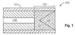
図1は、本発明の特定の実施形態によるカニューレ101内のマルチスポット発生器102を備えている光学手術用プローブ用のハンドピース100の遠位端部を示しており、この「遠位」という用語は、プローブ100に沿ってターゲットエリアに向かう方向を意味し、その反意語である「近位」は、反対の方向を意味している。図示の実施形態においては、マルチスポット発生器102は、近位の、カット面を有する光学要素104と、遠位の、カット面を有する光学要素106と、を備えている。本明細書において、「カット面を有する」とは、複数のサブ表面(カット面)から形成された端部表面を有し、面と面との間の交差部が滑らかにならないようにされた、光学要素を意味している。これらのカット面は、平坦であってよいが、平坦であることは、必須ではない。例えば、カット面は、別のサブ表面と交差する湾曲したサブ表面であって、曲率がサブ表面の交差部に跨って滑らかにならないようになっているものでもよく、このような実施形態は、光学上の集束能力を与える。
FIG. 1 shows the distal end of a
本発明は、光源が、レーザーを備え、光誘導路108は、光ビームを、近位の、カット面を有する光学要素104の、近位の平坦な面に送る。光誘導路108は、理論的には、ハンドピース100の遠位端部に光を伝達するのに適切な構造であれば、どんなものでもよいが、手術の用途においては、光ファイバが最も一般的に利用されている。ハンドピース100の遠位端部は、23ゲージ以下のサイズである。光誘導路108からの放射ビームの中心軸を「ビーム経路」と呼称する。光ビームは、光誘導路108から離れると、光誘導路108に結合されている光ビームの開口数の度合に応じて、発散する。この理由から、カット面を有する光学要素のカットされた光学表面は、発散するビームの各部分が異なる場所に屈折するように、光誘導路108の遠位端部から離されている。本発明の様々な実施形態では、少なくとも1つのカット面を、カット面の中心でカット面に対して垂直の方向が放射された光ビームのビーム経路に対して平行にならないように、方向付けしている。本明細書においては、このようなカット面を「ビーム経路に対して傾斜」していると表現する。
In the present invention, the light source comprises a laser, and the
カット面を有する光学要素104及び106は、それぞれ、異なる屈折率を有し、光誘導路108を出たビームが、発散し、近位の光学要素104の凹状のカット面と遠位の光学要素106の凸状のカット面との間のカットされた境界面が、遠位の光学要素106の遠位の平坦な面から出現する多数のスポットを生成する。この文脈における「凹状」及び「凸状」とは、カットされた表面が、ビーム経路に沿って光学要素の内側に形成されているか、或いは、外側に形成されているかを意味している。遠位の、カット面を有する光学要素106と、手術用プローブが挿入される媒体と、の相対屈折率に応じて、スポットは、光学要素106の遠位面から媒体内に入ると、更に発散する可能性がある。手術用プローブが食塩水中において利用されるように設計されている特定の例においては、例えば、近位の、カット面を有する光学要素104が、1.36の屈折率を有し、遠位の、カット面を有する光学要素が、1.58の屈折率を有するとすれば、カット面とビーム経路との間の角度が33〜55度の範囲内にあると仮定した場合に、約4mm離れたターゲットに対して1ミリメートルのオーダーのスポット間隔を生成することができる。
図示の実施形態において、光学要素104及び106は、それぞれ、光誘導路からの光ビームの中心に一致するビーム経路に対して傾斜した、4つの三角形のカット面を有し、マルチスポット発生器102が、4つの出力スポットを生成する。但し、原則的には、カット面の数と形状とは、望ましい出力スポットのパターンを生成するように調節することができる。例えば、カット面の数を増大させることができる。別の例においては、中心スポットが多数のスポットによって取り囲まれるようにするために、ビーム経路に対して垂直な、中央の平坦なカット面を、傾斜配置した複数のカット面で取り囲むようにすることができる。
In the illustrated embodiment, the
カット面を有する光学要素104及び106は、光学接着剤で成形すると、有利である。光学接着剤を利用した、カット面を有する光学要素の成形は、いくつかの技術的利点を有している。1つの利点は、カット面を有する光学要素104及び106の屈折率を、多数の入手可能な材料から選択することができるという点にある。別の利点は、硬い屈折材料に比べて、カットされた表面を成形することが容易であることであり、硬い屈折材料は、適切な形状への成形、エッチング、切削、又は機械加工が困難である。第3の利点は、光学接着剤材料は、比較的壊れやすい回折格子のような他の光学要素と比べた場合、使用上比較的丈夫であるという点にある。第4の利点は、光学接着剤を他の光学要素の周りに形成することができ、光学接着剤と他の光学要素とを、マルチスポットパターンを生成する際に、相互に作用させることができるという点にある。
The
カット面を有する光学要素を、別の光学要素の周りに形成することができる方法の一例として、図2は、ボールレンズ206の周りに形成された、カット面を有する光学要素204を備える、本発明の特定の実施形態によるマルチスポット発生器202を示している。ボールレンズ206の主な機能は、ボールレンズ206の遠位側でコリメートされるか又は収束するように、入射ビームを集束させることである。ボールレンズ206は、光源からの光がレンズを透過するように屈折材料で形成された、球面レンズ又は近似球面のレンズなら、どんなものでもよい。コリメートされた又は収束するビームへ集束させるために、ボールレンズの屈折率は、包囲している接着剤媒の屈折率よりも大きくなければならない。一例は、約1.76の可視光屈折率を有するサファイアボールレンズと、1.57〜1.58という低い屈折率の接着剤である。図示の実施形態においては、カット面を有する光学要素204の凸状のカットされた端部表面208は、カットされた端部表面208が光誘導路108の遠位端部から間隔をあけて光誘導路108の方向を向くように、構成されている。従って、放射された光ビームの各部分は、カット面を有する光学要素204によって多数のスポットに屈折し、これらのスポットは、ボールレンズ206を通って、カット面を有する光学要素204の平坦な遠位表面から外部に伝達される。更なる実施形態においては、カットされた端部表面208は、凹状とすることができる。ボールレンズ206は、様々なスポットに導かれるビームを、ある程度、収束させることができ、ハンドピース100の端部からの距離が増大した場合に急激に広がらないマルチスポットパターンを生成することができ、従って、マルチスポットパターンを、ハンドピース100の遠位端部とターゲットエリアとの間の間隔が多少変動しても、より一定したスポット間隔を有するようにすることができる。
As an example of how an optical element having a cut surface can be formed around another optical element, FIG. 2 shows a book comprising an optical element 204 having a cut surface formed around a ball lens 206. Fig. 2 shows a
更なる実施形態は、近位の集束レンズと、カット面を有する光学要素のカットされた表面と、を内蔵している。図3は、近位の、カット面を有する光学要素304と、遠位の、カット面を有する光学要素306と、円筒形の屈折率分布型(GRadient INdex:GRIN)レンズ308と、を組み込んだ、マルチスポット発生器302の一例を示している。光誘導路108から放射された光ビームは、広がり、次に、GRINレンズ308により、コリメート又は収束される。このコリメート又は収束された光ビームは、次に、近位の、カット面を有する光学要素304の、平坦な近位面に進入し、コリメート又は収束された光ビームの各部分は、カット面を有する光学要素304と306との、カットされた表面の間の境界面を通過するときに、多数のスポットに屈折する。前述の実施形態と同様に、この結果、遠位の光学要素306の平坦な遠位面から放射されるマルチスポット出力ビームが生成される。ビームがGRINレンズによってコリメート又は収束されているため、カット面を有する光学要素304と306との、傾斜したカット面は、図1の実施形態と比べた場合に、例えば15〜35度の範囲内のように、ビーム経路に関してより浅く傾斜させることができる一方、ターゲットゾーンにおける多数のスポット間に、同一程度の広がりを生成することができる。
A further embodiment incorporates a proximal focusing lens and a cut surface of an optical element having a cut surface. FIG. 3 incorporates a proximal, cut-surface
図4は、カット面を有する光学要素を、異なる屈折率を有する光学接着剤で形成する方法の一実施例を示す、フローチャート400である。ステップ402において、第1の光学接着剤を、手術ハンドピースのカニューレ内に堆積させる。特定の例においては、このステップにおいて、センタリングシリンダを利用し、光ファイバをカニューレ内に配置してもよく、第1の光学接着剤を光ファイバの遠位端部上に直接堆積させてもよい。別の例においては、GRINレンズを、カニューレ内に、光誘導路の遠位端部に配置することが可能であり、第1の光学接着剤を、GRINレンズの遠位端部上に堆積させることができる。ステップ404において、カットされた表面を、光学接着剤に形成する。例えば、凸状の、面をカットされた形状を有するピンを、カニューレの遠位端部から光学接着剤内に鋳込み、光学接着剤に凹状のカットされた表面を生成してもよい。光学接着剤を成形する適切な技術なら何でも利用でき、精密成形技術を利用して、常に正確に接着剤のカットされた表面を生成することができれば、特に有利である。次に、ステップ406では、例えば紫外線(UV)や、熱や、化学硬化剤等、に晒すことにより、第1の光学接着剤を硬化させ、これにより、第1の光学接着剤を所望の形状で固め、成形用のピンを取り除くことができるようにする。
FIG. 4 is a
ステップ408では、予め硬化させた光学接着剤の、遠位の面上に、第2の光学接着剤を堆積させる。第2の光学接着剤は、第1の光学接着剤の凹状のカット面に適合し、第2の光学接着剤に、凸状のカット面を生成する。第2の光学接着剤の遠位表面は、次に、型板を押し付けることにより、平坦化してもよい。或いは、光学接着剤の堆積を他の方法で制御して、望ましい形状を生成することができ、例えば、閉じた成形容積内に導入する等によって、望ましい形状を生成することもできる。後者の場合には、必要に応じて、2つのカットされた表面を形成することもできる。ステップ410では、第2の光学接着剤を硬化させて、第2の光学接着剤を望ましい形状に固める。第1の及び第2の光学接着剤に対して、異なる硬化プロセスを利用してもよい。例えば、接着剤を光によって硬化させる場合には、第2の接着剤を硬化させるために利用される光の波長は、第1の接着剤を硬化させるために利用される波長と異なってもよく、第1の接着剤が、硬化放射線に過度に晒されて、マイナスの影響を受けないようにすることができる。光硬化型の接着剤の別の実施形態では、第2の光学接着剤を成形するために利用される型板又は他の閉じた成形型を、硬化放射線に対して透過性を有する材料(例えば、UV硬化放射線の場合には、石英等)で製造してもよく、第2の接着剤を、型板が存在しても硬化できるようにすることができる。型板は、次に、硬化の後に、除去することができる。第1の及び第2の光学接着剤を有するカニューレは、次に、ステップ412で、手術用ハンドピースに組み込まれ、この方法は完了する。
In
図5は、本発明の別の実施形態により、別の光学要素の周りにカット面を有する光学要素を形成する方法の、一実施例を示すフローチャート500である。ステップ502では、光学接着剤を、ボールレンズの周りの型板上に堆積させる。ステップ504では、ボールレンズの周りに形成された光学接着剤を、カニューレの遠位端部に押し込む。型板は、カニューレとのアライメントを円滑に行うために、カニューレガイド部を備えることができる。光学接着剤をカニューレに押し込むと、過剰な光学接着剤がカニューレから押し出され、堆積させる接着剤の量を十分に慎重に制御すれば、常に正確な量の光学接着剤が最終的にカニューレ内に残る。
FIG. 5 is a
ステップ506では、カットされた表面を、光学接着剤の近位端部に形成する。カットされた表面は、凸状又は凹状とすることができる。カットされた表面は、例えば、端部上に相補的なカットされた表面を有するピンを利用し、このピンをカニューレの近位端部に挿入することにより、形成してもよい。ステップ508では、光学接着剤を硬化させ、光学接着剤を望ましい形状に固め、型ピン及び型板を取り除くことができる。ステップ510では、ハンドピースとカニューレとを組み立て、この方法を完了する。
In step 506, a cut surface is formed at the proximal end of the optical adhesive. The cut surface can be convex or concave. The cut surface may be formed, for example, by utilizing a pin having a complementary cut surface on the end and inserting the pin into the proximal end of the cannula. In
本発明は、本明細書では、一例として示されており、従って、当業者は、様々な変更を行うことができる。本発明を詳細に説明したが、特許請求されている本発明の範囲を逸脱することなしに、様々な変更、置換、及び代替を実施することができることを、理解されたい。 The present invention is illustrated herein by way of example, and various modifications can be made by those skilled in the art. Although the invention has been described in detail, it should be understood that various changes, substitutions and alternatives can be made without departing from the scope of the claimed invention.
Claims (14)
前記ハンドピース内の少なくとも1つの光誘導路であって、前記光源から前記ハンドピースの遠位端部まで光ビームを運ぶように構成された、少なくとも1つの光誘導路と、
前記ハンドピースの遠位端部におけるマルチスポット発生器であって、前記マルチスポット発生器が、カット面を有する光学要素を備え、前記カット面を有する光学要素の、カットされた端部表面が、前記光誘導路の遠位端部から間隔をあけて配置され、前記光ビームの経路に対して傾斜した平坦なカット面を備え、
前記マルチスポット発生器が、更に、ボールレンズを有し、
前記ボールレンズが、前記カット面を有する光学要素の内部にあり、
前記マルチスポット発生器が、前記光ビームを多数のビームに分割し、前記多数のビームの各部分を、多数のスポットに方向づける、
光学手術用プローブ。 A handpiece configured to optically couple to a light source;
At least one light guide path in the handpiece, the light guide path configured to carry a light beam from the light source to a distal end of the handpiece;
A multi-spot generator at the distal end of the handpiece, the multi-spot generator comprising an optical element having a cut surface, wherein the cut end surface of the optical element having the cut surface is A flat cut surface disposed at a distance from a distal end of the light guide path and inclined with respect to the path of the light beam;
The multi-spot generator further comprises a ball lens;
The ball lens is inside an optical element having the cut surface;
The multi-spot generator splits the light beam into multiple beams and directs portions of the multiple beams to multiple spots;
Optical surgical probe.
前記ハンドピース内の少なくとも1つの光誘導路であって、前記光源から前記ハンドピースの遠位端部まで光ビームを運ぶように構成された、少なくとも1つの光誘導路と、At least one light guide path in the handpiece, the light guide path configured to carry a light beam from the light source to a distal end of the handpiece;
前記ハンドピースの遠位端部におけるマルチスポット発生器であって、前記マルチスポット発生器が、近位の、カット面を有する光学要素と、遠位の、カット面を有する光学要素と、を備え、前記近位及び遠位の、カット面を有する光学要素の、カットされた端部表面が、前記光誘導路の遠位端部から間隔をあけて配置され、前記光ビームの経路に対して傾斜した平坦なカット面を備え、前記マルチスポット発生器が、前記光ビームを多数のビームに分割し、前記多数のビームの各部分を、多数のスポットに方向づける、A multi-spot generator at the distal end of the handpiece, the multi-spot generator comprising a proximal, cut-surface optical element and a distal, cut-surface optical element A cut end surface of the proximal and distal optical elements having a cut surface is spaced from the distal end of the light guide path and is relative to the path of the light beam An inclined flat cut surface, wherein the multi-spot generator divides the light beam into multiple beams and directs portions of the multiple beams to multiple spots;
光学手術用プローブ。Optical surgical probe.
前記方法が、
ハンドピース用のカニューレ内に光学接着剤を堆積させるステップであって、前記ハンドピースが、光ビームを、光源から前記ハンドピースを介して運ぶように構成された少なくとも1つの光誘導路を備えている、ステップと、
前記ボールレンズの周りに前記光学接着剤を成形して、前記光ビームの経路に対して傾斜した平坦なカットされた面を生成するステップと、
前記光学接着剤を硬化させるステップと、
前記カニューレと前記ハンドピースとを組み立て、前記ボールレンズの周りに前記光学接着剤を備えているマルチスポット発生器を、前記ハンドピースの遠位端部に形成するステップと、
を有し、
前記マルチスポット発生器が、前記光ビームを多数のビームに分割し、前記多数のビームの各部分を、多数のスポットに方向づける、
方法。 A method of manufacturing a multi-spot optical surgical probe, wherein the ball lens is inside an optical element having a cut surface , comprising:
The method comprises
Depositing optical adhesive in a cannula for the handpiece, the handpiece comprising at least one light guide path configured to carry a light beam from a light source through the handpiece; Step, and
Molding the optical adhesive around the ball lens to produce a flat cut surface inclined relative to the path of the light beam ;
Curing the optical adhesive;
Assembling the cannula and the handpiece and forming a multi-spot generator at the distal end of the handpiece comprising the optical adhesive around the ball lens ;
I have a,
The multi-spot generator splits the light beam into multiple beams and directs portions of the multiple beams to multiple spots;
Method.
前記方法が、
前記第1の屈折率とは異なる第2の屈折率を有する第2の光学接着剤を、前記第1の光学接着剤の前記カットされた面上に堆積させるステップと、
前記第2の光学接着剤を硬化させるステップと、
を更に有する、請求項11に記載の方法。 The optical adhesive is a first optical adhesive having a first refractive index;
The method comprises
Depositing a second optical adhesive having a second refractive index different from the first refractive index on the cut surface of the first optical adhesive;
Curing the second optical adhesive;
The method of claim 11 , further comprising:
Applications Claiming Priority (3)
| Application Number | Priority Date | Filing Date | Title |
|---|---|---|---|
| US28540009P | 2009-12-10 | 2009-12-10 | |
| US61/285,400 | 2009-12-10 | ||
| PCT/US2010/058942 WO2011071776A1 (en) | 2009-12-10 | 2010-12-03 | Multi-spot laser surgical probe using faceted optical elements |
Publications (3)
| Publication Number | Publication Date |
|---|---|
| JP2013513430A JP2013513430A (en) | 2013-04-22 |
| JP2013513430A5 JP2013513430A5 (en) | 2014-01-23 |
| JP5753186B2 true JP5753186B2 (en) | 2015-07-22 |
Family
ID=44142708
Family Applications (1)
| Application Number | Title | Priority Date | Filing Date |
|---|---|---|---|
| JP2012543172A Active JP5753186B2 (en) | 2009-12-10 | 2010-12-03 | Multi-spot laser surgical probe using an optical element having a cut surface |
Country Status (14)
| Country | Link |
|---|---|
| US (3) | US8764261B2 (en) |
| EP (1) | EP2509525B1 (en) |
| JP (1) | JP5753186B2 (en) |
| KR (1) | KR101689250B1 (en) |
| CN (1) | CN102791213B (en) |
| AR (1) | AR082752A1 (en) |
| AU (1) | AU2010328437B2 (en) |
| BR (1) | BR112012013750A2 (en) |
| CA (1) | CA2781677C (en) |
| ES (1) | ES2557883T3 (en) |
| MX (1) | MX2012006536A (en) |
| RU (1) | RU2540913C2 (en) |
| TW (1) | TWI522081B (en) |
| WO (1) | WO2011071776A1 (en) |
Families Citing this family (40)
| Publication number | Priority date | Publication date | Assignee | Title |
|---|---|---|---|---|
| US8256430B2 (en) | 2001-06-15 | 2012-09-04 | Monteris Medical, Inc. | Hyperthermia treatment and probe therefor |
| US8728092B2 (en) | 2008-08-14 | 2014-05-20 | Monteris Medical Corporation | Stereotactic drive system |
| US8747418B2 (en) | 2008-08-15 | 2014-06-10 | Monteris Medical Corporation | Trajectory guide |
| WO2011071776A1 (en) | 2009-12-10 | 2011-06-16 | Alcon Research, Ltd. | Multi-spot laser surgical probe using faceted optical elements |
| AU2012294723B2 (en) * | 2011-08-09 | 2016-06-09 | Alcon Inc. | Multi-spot laser surgical probe using faceted optical elements |
| US8496331B2 (en) | 2011-08-12 | 2013-07-30 | Alcon Research, Ltd. | Portable pattern-generating ophthalmic probe |
| US9849034B2 (en) | 2011-11-07 | 2017-12-26 | Alcon Research, Ltd. | Retinal laser surgery |
| US8571364B2 (en) * | 2011-11-09 | 2013-10-29 | Alcon Research, Ltd. | Multi-spot laser probe with faceted optical element |
| CN104602638B (en) | 2012-06-27 | 2017-12-19 | 曼特瑞斯医药有限责任公司 | System for influenceing to treat tissue |
| US9308128B2 (en) * | 2013-01-08 | 2016-04-12 | Novartis Ag | Multi-spot laser probe with micro-structured faceted proximal surface |
| US20140200566A1 (en) * | 2013-01-15 | 2014-07-17 | Alcon Research, Ltd. | Multi-spot laser probe with micro-structured distal surface |
| WO2015143025A1 (en) | 2014-03-18 | 2015-09-24 | Monteris Medical Corporation | Image-guided therapy of a tissue |
| US9504484B2 (en) | 2014-03-18 | 2016-11-29 | Monteris Medical Corporation | Image-guided therapy of a tissue |
| US10675113B2 (en) | 2014-03-18 | 2020-06-09 | Monteris Medical Corporation | Automated therapy of a three-dimensional tissue region |
| US9681793B2 (en) | 2014-06-19 | 2017-06-20 | Novartis Ag | Surgical probe with interlocking attachment |
| FR3026940B1 (en) | 2014-10-08 | 2021-09-03 | Univ Jean Monnet | DEVICE AND METHOD FOR CUTTING A HORN OR A CRYSTALLINE |
| US9766041B2 (en) | 2014-12-08 | 2017-09-19 | The Charles Stark Draper Laboratory, Inc. | Multi-target optical designator |
| US10111778B2 (en) * | 2014-12-19 | 2018-10-30 | Novartis Ag | BSS-only multi-sport laser probe |
| US10327830B2 (en) | 2015-04-01 | 2019-06-25 | Monteris Medical Corporation | Cryotherapy, thermal therapy, temperature modulation therapy, and probe apparatus therefor |
| US10278785B2 (en) | 2015-12-18 | 2019-05-07 | Novartis Ag | Method of making diverging-light fiber optics illumination delivery system |
| HUE061958T2 (en) | 2016-04-06 | 2023-09-28 | Keranova | Optical focusing system of a cutting apparatus including a light spatial modulator |
| JP6773314B2 (en) * | 2016-08-03 | 2020-10-21 | 株式会社Okファイバーテクノロジー | Laser irradiation device |
| CN110621272A (en) * | 2017-05-16 | 2019-12-27 | 爱尔康公司 | Laser probe for panretinal photocoagulation including lensed optical fiber |
| US10639198B2 (en) | 2017-05-30 | 2020-05-05 | Alcon Inc. | Multi-fiber multi-spot laser probe with articulating beam separation |
| US11284940B2 (en) * | 2017-10-24 | 2022-03-29 | Gyrus Acmi, Inc. | Combined laser beam splitter retrieval device |
| JP2021502848A (en) | 2017-11-14 | 2021-02-04 | アルコン インコーポレイティド | Multi-spot laser probe with irradiation function |
| WO2019116280A1 (en) * | 2017-12-12 | 2019-06-20 | Novartis Ag | Laser probe |
| US11213426B2 (en) | 2017-12-12 | 2022-01-04 | Alcon Inc. | Thermally robust multi-spot laser probe |
| EP3709942B1 (en) | 2017-12-12 | 2023-09-13 | Alcon Inc. | Multiple-input-coupled illuminated multi-spot laser probe |
| AU2018383137B2 (en) | 2017-12-12 | 2024-05-02 | Alcon Inc. | Thermally robust laser probe assembly |
| WO2019116283A1 (en) | 2017-12-12 | 2019-06-20 | Novartis Ag | Surgical probe with shape-memory material |
| US10806329B2 (en) | 2018-01-24 | 2020-10-20 | Canon U.S.A., Inc. | Optical probes with optical-correction components |
| US10816789B2 (en) * | 2018-01-24 | 2020-10-27 | Canon U.S.A., Inc. | Optical probes that include optical-correction components for astigmatism correction |
| US10561303B2 (en) | 2018-01-24 | 2020-02-18 | Canon U.S.A., Inc. | Optical probes with correction components for astigmatism correction |
| US10606064B2 (en) | 2018-01-24 | 2020-03-31 | Canon U.S.A., Inc. | Optical probes with astigmatism correction |
| US10234676B1 (en) | 2018-01-24 | 2019-03-19 | Canon U.S.A., Inc. | Optical probes with reflecting components for astigmatism correction |
| US10791923B2 (en) | 2018-09-24 | 2020-10-06 | Canon U.S.A., Inc. | Ball lens for optical probe and methods therefor |
| DE102019108559A1 (en) * | 2019-04-02 | 2020-10-08 | Endress+Hauser Process Solutions (Deutschland) GmbH | Refractometer and method for determining the refractive index of a process medium with a refractometer |
| EP3975952A1 (en) | 2019-06-03 | 2022-04-06 | Alcon Inc. | Aligning multi-wavelength laser beams with cores of a multi-core fiber |
| US11209595B2 (en) * | 2020-01-27 | 2021-12-28 | Lumentum Operations Llc | Retroreflective fiber endcap |
Family Cites Families (40)
| Publication number | Priority date | Publication date | Assignee | Title |
|---|---|---|---|---|
| US4209017A (en) * | 1970-08-13 | 1980-06-24 | Shaw Robert F | Surgical instrument having self-regulating radiant heating of its cutting edge and method of using the same |
| US4669818A (en) * | 1981-01-21 | 1987-06-02 | Hughes Aircraft Company | Miniature window |
| US5163936A (en) * | 1991-01-22 | 1992-11-17 | Reliant Laser Corp. | Endoscopic mirror laser beam delivery system and method for controlling alignment |
| EP0634947B1 (en) * | 1992-04-10 | 2001-12-19 | Surgilight,Inc. | Apparatus for performing eye surgery |
| US5396571A (en) * | 1993-05-21 | 1995-03-07 | Trimedyne, Inc. | Coupling device and method for improved transfer efficiency of light energy from a laser source into optical fibers |
| US5451221A (en) * | 1993-12-27 | 1995-09-19 | Cynosure, Inc. | Endoscopic light delivery system |
| US5534000A (en) * | 1994-03-17 | 1996-07-09 | Endeavor Surgical Products, Inc. | Laser fiber apparatus having a contact tip and adjacent diffuser element and surgical methods for using same |
| US5630788A (en) * | 1994-08-12 | 1997-05-20 | Imagyn Medical, Inc. | Endoscope with curved end image guide |
| US5921981A (en) * | 1995-11-09 | 1999-07-13 | Alcon Laboratories, Inc. | Multi-spot laser surgery |
| US6011889A (en) * | 1996-04-29 | 2000-01-04 | Eclipse Surgical Technologies, Inc. | Piercing point optical fiber device for laser surgery procedures |
| US5751869A (en) * | 1996-08-08 | 1998-05-12 | Cogent Light Technologies, Inc. | Optical system for coupling light from a single fiber optic into a fiber bundle |
| US20010041884A1 (en) * | 1996-11-25 | 2001-11-15 | Frey Rudolph W. | Method for determining and correcting vision |
| US6162211A (en) * | 1996-12-05 | 2000-12-19 | Thermolase Corporation | Skin enhancement using laser light |
| DE19708776C1 (en) | 1997-03-04 | 1998-06-18 | Fraunhofer Ges Forschung | Anti-reflection coating for glass or plastics panels used in windows, display screens etc. |
| CA2263214A1 (en) * | 1998-02-27 | 1999-08-27 | Eclipse Surgical Technologies, Inc. | Viewing surgical scope for minimally invasive procedures |
| US6487440B2 (en) * | 1998-07-08 | 2002-11-26 | Lifespex, Inc. | Optical probe having and methods for difuse and uniform light irradiation |
| JP2002536683A (en) * | 1999-02-05 | 2002-10-29 | コーニング インコーポレイテッド | Optical fiber member having shaped optical element and method of manufacturing the same |
| JP2001290037A (en) * | 2000-04-05 | 2001-10-19 | Canon Inc | Plastic optical fiber with lens, light receiving and emitting device and manufacturing method therefor |
| WO2002050584A2 (en) * | 2000-12-21 | 2002-06-27 | Biovalve Technologies, Inc. | Microneedle array systems |
| US20060004347A1 (en) * | 2000-12-28 | 2006-01-05 | Palomar Medical Technologies, Inc. | Methods and products for producing lattices of EMR-treated islets in tissues, and uses therefor |
| AU2002361073A1 (en) * | 2001-11-29 | 2003-06-10 | Sumitomo Electric Industries, Ltd. | Method and metal mold for manufacturing optical connector ferrule, optical connector ferrule manufactured by using the method, and optical connector and optical wiring system using the ferrule |
| JP4475501B2 (en) * | 2003-10-09 | 2010-06-09 | インターナショナル・ビジネス・マシーンズ・コーポレーション | Spectroscopic element, diffraction grating, composite diffraction grating, color display device, and duplexer |
| US20080132886A1 (en) * | 2004-04-09 | 2008-06-05 | Palomar Medical Technologies, Inc. | Use of fractional emr technology on incisions and internal tissues |
| CN101076744B (en) * | 2004-04-23 | 2010-05-12 | 光处方革新有限公司 | Optical manifold for light-emitting diodes |
| US20070121069A1 (en) * | 2005-11-16 | 2007-05-31 | Andersen Dan E | Multiple spot photomedical treatment using a laser indirect ophthalmoscope |
| US7474820B2 (en) | 2006-04-27 | 2009-01-06 | Invuity, Inc. | Micro-optic adapters and tips for surgical illumination fibers |
| WO2008045316A2 (en) * | 2006-10-06 | 2008-04-17 | Surgiquest, Incorporated | Visualization trocar |
| US20080108979A1 (en) * | 2006-11-03 | 2008-05-08 | William Telfair | Flush Tip Illuminating Laser Probe Treatment Apparatus |
| JP4704386B2 (en) * | 2007-03-29 | 2011-06-15 | オリンパスメディカルシステムズ株式会社 | Endoscope |
| US7566173B2 (en) | 2007-07-09 | 2009-07-28 | Alcon, Inc. | Multi-spot ophthalmic laser probe |
| JP5192247B2 (en) * | 2008-01-29 | 2013-05-08 | 並木精密宝石株式会社 | OCT probe |
| EP2157462A1 (en) | 2008-08-22 | 2010-02-24 | Pulsion Medical Systems AG | Fiber-optic probe |
| ES2552799T3 (en) | 2009-11-24 | 2015-12-02 | Alcon Research, Ltd. | Single fiber multipoint laser probe for ophthalmic endoillumination |
| WO2011071776A1 (en) | 2009-12-10 | 2011-06-16 | Alcon Research, Ltd. | Multi-spot laser surgical probe using faceted optical elements |
| EP2512584B1 (en) | 2009-12-15 | 2016-06-08 | Alcon Research, Ltd | Multi-spot laser probe |
| US20120099112A1 (en) | 2010-10-25 | 2012-04-26 | Gerard Argant Alphonse | Multi-core low reflection lateral output fiber probe |
| US8496331B2 (en) * | 2011-08-12 | 2013-07-30 | Alcon Research, Ltd. | Portable pattern-generating ophthalmic probe |
| US9308128B2 (en) | 2013-01-08 | 2016-04-12 | Novartis Ag | Multi-spot laser probe with micro-structured faceted proximal surface |
| US20140200566A1 (en) | 2013-01-15 | 2014-07-17 | Alcon Research, Ltd. | Multi-spot laser probe with micro-structured distal surface |
| US10111778B2 (en) * | 2014-12-19 | 2018-10-30 | Novartis Ag | BSS-only multi-sport laser probe |
-
2010
- 2010-12-03 WO PCT/US2010/058942 patent/WO2011071776A1/en active Application Filing
- 2010-12-03 KR KR1020127017700A patent/KR101689250B1/en active IP Right Grant
- 2010-12-03 JP JP2012543172A patent/JP5753186B2/en active Active
- 2010-12-03 CA CA2781677A patent/CA2781677C/en not_active Expired - Fee Related
- 2010-12-03 EP EP10836457.1A patent/EP2509525B1/en active Active
- 2010-12-03 RU RU2012128828/14A patent/RU2540913C2/en not_active IP Right Cessation
- 2010-12-03 ES ES10836457.1T patent/ES2557883T3/en active Active
- 2010-12-03 MX MX2012006536A patent/MX2012006536A/en active IP Right Grant
- 2010-12-03 AU AU2010328437A patent/AU2010328437B2/en not_active Ceased
- 2010-12-03 CN CN201080055631.3A patent/CN102791213B/en not_active Expired - Fee Related
- 2010-12-03 US US12/959,533 patent/US8764261B2/en active Active
- 2010-12-03 BR BR112012013750A patent/BR112012013750A2/en active Search and Examination
- 2010-12-09 TW TW099142996A patent/TWI522081B/en not_active IP Right Cessation
- 2010-12-10 AR ARP100104586A patent/AR082752A1/en unknown
-
2014
- 2014-05-19 US US14/280,951 patent/US9572479B2/en active Active
-
2017
- 2017-01-03 US US15/397,283 patent/US10660704B2/en active Active
Also Published As
| Publication number | Publication date |
|---|---|
| TW201125531A (en) | 2011-08-01 |
| US9572479B2 (en) | 2017-02-21 |
| BR112012013750A2 (en) | 2016-03-15 |
| EP2509525A4 (en) | 2013-08-14 |
| TWI522081B (en) | 2016-02-21 |
| US20170112573A1 (en) | 2017-04-27 |
| US8764261B2 (en) | 2014-07-01 |
| CN102791213B (en) | 2015-01-21 |
| AU2010328437A1 (en) | 2012-06-14 |
| RU2012128828A (en) | 2014-01-20 |
| US10660704B2 (en) | 2020-05-26 |
| CA2781677C (en) | 2017-07-11 |
| US20110141759A1 (en) | 2011-06-16 |
| CA2781677A1 (en) | 2011-06-16 |
| EP2509525A1 (en) | 2012-10-17 |
| MX2012006536A (en) | 2012-07-17 |
| RU2540913C2 (en) | 2015-02-10 |
| AU2010328437B2 (en) | 2015-01-22 |
| KR101689250B1 (en) | 2016-12-23 |
| JP2013513430A (en) | 2013-04-22 |
| ES2557883T3 (en) | 2016-01-29 |
| CN102791213A (en) | 2012-11-21 |
| AR082752A1 (en) | 2013-01-09 |
| WO2011071776A1 (en) | 2011-06-16 |
| KR20120104298A (en) | 2012-09-20 |
| US20140250668A1 (en) | 2014-09-11 |
| EP2509525B1 (en) | 2015-12-02 |
Similar Documents
| Publication | Publication Date | Title |
|---|---|---|
| JP5753186B2 (en) | Multi-spot laser surgical probe using an optical element having a cut surface | |
| US9429746B2 (en) | Micro-optic adapters and tips for surgical illumination fibers | |
| CN104936506B (en) | More light spot laser probes with micro-structure multiaspect proximal end face | |
| JP6110399B2 (en) | Multi-spot laser probe with facet optics | |
| KR20140102206A (en) | Varying beam parameter product of a laser beam | |
| JP2013513430A5 (en) | ||
| US8837883B2 (en) | Shaping laser beam launches into optical fibers to yield specific output effects | |
| JP2016502920A (en) | Multi-spot laser probe with microstructured distal surface | |
| CN108368990A (en) | So that illuminating the light diverging of conveyer system from optical fiber optical device | |
| CN217281623U (en) | Laser homogenization system and laser system with same | |
| CN107076938A (en) | Method for the lock pin using laser treatment multi fiber | |
| US20210186612A1 (en) | Optical probe | |
| Zinn et al. | F2-laser fabrication of fiber-integrated optical elements | |
| Veiko et al. | New method of fiber optic tool fabrication based on laser technologies |
Legal Events
| Date | Code | Title | Description |
|---|---|---|---|
| A521 | Request for written amendment filed |
Free format text: JAPANESE INTERMEDIATE CODE: A523 Effective date: 20131202 |
|
| A621 | Written request for application examination |
Free format text: JAPANESE INTERMEDIATE CODE: A621 Effective date: 20131202 |
|
| A977 | Report on retrieval |
Free format text: JAPANESE INTERMEDIATE CODE: A971007 Effective date: 20140814 |
|
| A131 | Notification of reasons for refusal |
Free format text: JAPANESE INTERMEDIATE CODE: A131 Effective date: 20140819 |
|
| A521 | Request for written amendment filed |
Free format text: JAPANESE INTERMEDIATE CODE: A523 Effective date: 20141114 |
|
| TRDD | Decision of grant or rejection written | ||
| A01 | Written decision to grant a patent or to grant a registration (utility model) |
Free format text: JAPANESE INTERMEDIATE CODE: A01 Effective date: 20150421 |
|
| A61 | First payment of annual fees (during grant procedure) |
Free format text: JAPANESE INTERMEDIATE CODE: A61 Effective date: 20150521 |
|
| R150 | Certificate of patent or registration of utility model |
Ref document number: 5753186 Country of ref document: JP Free format text: JAPANESE INTERMEDIATE CODE: R150 |
|
| R250 | Receipt of annual fees |
Free format text: JAPANESE INTERMEDIATE CODE: R250 |
|
| R250 | Receipt of annual fees |
Free format text: JAPANESE INTERMEDIATE CODE: R250 |
|
| S111 | Request for change of ownership or part of ownership |
Free format text: JAPANESE INTERMEDIATE CODE: R313111 Free format text: JAPANESE INTERMEDIATE CODE: R313113 |
|
| R350 | Written notification of registration of transfer |
Free format text: JAPANESE INTERMEDIATE CODE: R350 |
|
| R250 | Receipt of annual fees |
Free format text: JAPANESE INTERMEDIATE CODE: R250 |
|
| R250 | Receipt of annual fees |
Free format text: JAPANESE INTERMEDIATE CODE: R250 |
|
| R250 | Receipt of annual fees |
Free format text: JAPANESE INTERMEDIATE CODE: R250 |
|
| R250 | Receipt of annual fees |
Free format text: JAPANESE INTERMEDIATE CODE: R250 |
|
| R250 | Receipt of annual fees |
Free format text: JAPANESE INTERMEDIATE CODE: R250 |