JP5751460B2 - Liquid ejector - Google Patents
Liquid ejector Download PDFInfo
- Publication number
- JP5751460B2 JP5751460B2 JP2010028877A JP2010028877A JP5751460B2 JP 5751460 B2 JP5751460 B2 JP 5751460B2 JP 2010028877 A JP2010028877 A JP 2010028877A JP 2010028877 A JP2010028877 A JP 2010028877A JP 5751460 B2 JP5751460 B2 JP 5751460B2
- Authority
- JP
- Japan
- Prior art keywords
- liquid
- ink
- ejecting
- ejection
- outlet
- Prior art date
- Legal status (The legal status is an assumption and is not a legal conclusion. Google has not performed a legal analysis and makes no representation as to the accuracy of the status listed.)
- Active
Links
Images


Classifications
-
- B—PERFORMING OPERATIONS; TRANSPORTING
- B41—PRINTING; LINING MACHINES; TYPEWRITERS; STAMPS
- B41J—TYPEWRITERS; SELECTIVE PRINTING MECHANISMS, i.e. MECHANISMS PRINTING OTHERWISE THAN FROM A FORME; CORRECTION OF TYPOGRAPHICAL ERRORS
- B41J2/00—Typewriters or selective printing mechanisms characterised by the printing or marking process for which they are designed
- B41J2/005—Typewriters or selective printing mechanisms characterised by the printing or marking process for which they are designed characterised by bringing liquid or particles selectively into contact with a printing material
- B41J2/01—Ink jet
- B41J2/135—Nozzles
- B41J2/165—Preventing or detecting of nozzle clogging, e.g. cleaning, capping or moistening for nozzles
- B41J2/16517—Cleaning of print head nozzles
- B41J2/1652—Cleaning of print head nozzles by driving a fluid through the nozzles to the outside thereof, e.g. by applying pressure to the inside or vacuum at the outside of the print head
- B41J2/16523—Waste ink collection from caps or spittoons, e.g. by suction
-
- B—PERFORMING OPERATIONS; TRANSPORTING
- B41—PRINTING; LINING MACHINES; TYPEWRITERS; STAMPS
- B41J—TYPEWRITERS; SELECTIVE PRINTING MECHANISMS, i.e. MECHANISMS PRINTING OTHERWISE THAN FROM A FORME; CORRECTION OF TYPOGRAPHICAL ERRORS
- B41J2/00—Typewriters or selective printing mechanisms characterised by the printing or marking process for which they are designed
- B41J2/005—Typewriters or selective printing mechanisms characterised by the printing or marking process for which they are designed characterised by bringing liquid or particles selectively into contact with a printing material
- B41J2/01—Ink jet
- B41J2/135—Nozzles
- B41J2/165—Preventing or detecting of nozzle clogging, e.g. cleaning, capping or moistening for nozzles
- B41J2/16505—Caps, spittoons or covers for cleaning or preventing drying out
- B41J2/16508—Caps, spittoons or covers for cleaning or preventing drying out connected with the printer frame
Description
本発明は、液体噴射装置に関する。 The present invention relates to a liquid ejecting apparatus.
液体を噴射する液体噴射装置として、例えば記録媒体に文字や画像等を記録するインクジェット式記録装置などが知られている。インクジェット式記録装置は、記録媒体を搬送しつつ、噴射ヘッドに設けられたノズルから当該記録媒体にインクを噴射することで、記録媒体に文字や画像等を形成する構成になっている。インクジェット式記録装置には、噴射ヘッドの噴射領域を覆うキャップが設けられている。 As a liquid ejecting apparatus that ejects liquid, for example, an ink jet recording apparatus that records characters and images on a recording medium is known. An ink jet recording apparatus is configured to form characters, images, and the like on a recording medium by ejecting ink onto the recording medium from a nozzle provided in an ejection head while conveying the recording medium. The ink jet recording apparatus is provided with a cap that covers the ejection area of the ejection head.
インクジェット式記録装置においては、インクの増粘や固化、塵埃の付着、さらには気泡の混入などにより噴射ヘッドのノズルに目詰まりが生じ、印刷不良を引き起こす場合がある。また、噴射ヘッドにインクを初期充填する際に、ヘッド内の液体をノズルから排出する必要がある。このため、記録媒体に対しての噴射とは別に、ノズル内の液体を強制的に排出させるフラッシング動作などのメンテナンス動作を行うように構成されている。 In an ink jet recording apparatus, the nozzles of the ejection head may become clogged due to thickening and solidification of ink, adhesion of dust, and mixing of air bubbles, which may cause printing failure. Further, when the ink is initially filled in the ejection head, the liquid in the head needs to be discharged from the nozzle. For this reason, apart from the jetting onto the recording medium, a maintenance operation such as a flushing operation for forcibly discharging the liquid in the nozzle is performed.
フラッシング動作では、噴射ヘッドから排出される液体を例えばキャップなどの液体受部を用いて受けるようにしている。キャップ内には、例えば受けたインクを流出させる流出口が設けられている。流出口には、例えばポンプなどの吸引部が接続されている。 In the flushing operation, the liquid discharged from the ejection head is received using a liquid receiving unit such as a cap. In the cap, for example, an outlet for letting out the received ink is provided. A suction part such as a pump is connected to the outlet.
近年、カラー印刷時の印字品質を向上するため、例えばマゼンタ、ライトマゼンタ、シアン、ライトシアン、イエロー、ブラックなどの多色のインクを使用するインクジェット式記録装置が提供されている。このように多色のインクを用いる場合、噴射ヘッドには色数に応じたノズル開口列を設ける必要があるため、例えば複数の噴射ヘッドを1つのキャリッジに搭載した構成が知られている(例えば、特許文献1参照)。特許文献1の構成では、複数の噴射ヘッドのそれぞれに対応した複数のキャップが設けられており、キャップ毎に別々のポンプが接続されている。 In recent years, in order to improve the printing quality during color printing, an ink jet recording apparatus using multicolor inks such as magenta, light magenta, cyan, light cyan, yellow, and black has been provided. When using multi-colored inks in this way, it is necessary to provide the nozzle heads in accordance with the number of colors in the ejection head. For example, a configuration in which a plurality of ejection heads are mounted on one carriage is known (for example , See Patent Document 1). In the configuration of Patent Document 1, a plurality of caps corresponding to each of the plurality of ejection heads are provided, and a separate pump is connected to each cap.
しかしながら、複数のキャップのそれぞれに対して別々のポンプを接続する構成では、吸引精度等のメンテナンス性の面で良好ではあるが、コストが高くなってしまう。
上記のような事情に鑑み、本発明は、低コスト化を図ることができる液体噴射装置を提供することを目的とする。
However, the configuration in which separate pumps are connected to each of the plurality of caps is good in terms of maintainability such as suction accuracy, but increases the cost.
In view of the circumstances as described above, it is an object of the present invention to provide a liquid ejecting apparatus capable of reducing the cost.
本発明に係る液体噴射装置は、液体を噴射するヘッド部と、前記ヘッド部から排出された前記液体を受けると共に、底部に前記液体の流出口が設けられた複数の液体受部と、複数の前記液体受部の前記流出口を共通して吸引する吸引部と、複数の前記液体受部にそれぞれ設けられ、前記液体に浮くように形成されると共に前記液体が流出された状態において前記流出口を閉塞する閉塞部材とを備え、複数の前記液体受部のそれぞれの前記閉塞部材が該液体受部内の前記液体に浮いた状態で、前記吸引ポンプを駆動し、いずれかの前記閉塞部材が前記流出口を閉塞した後も該吸引ポンプの駆動を継続することを特徴とする。
また、液体を噴射するヘッド部と、前記ヘッド部から排出され
た前記液体を受けると共に、底部に前記液体の流出口が設けられた複数の液体受部と、複
数の前記液体受部の前記流出口を共通して吸引する吸引部と、複数の前記液体受部にそれ
ぞれ設けられ、前記液体に浮くように形成されると共に前記液体が流出された状態におい
て前記流出口を閉塞する閉塞部材とを備えることを特徴とする。
A liquid ejecting apparatus according to the present invention includes a head unit that ejects liquid, a plurality of liquid receiving units that receive the liquid discharged from the head unit, and are provided with an outflow port for the liquid at the bottom, and a plurality of liquid receiving units A suction part that sucks the outlet of the liquid receiving part in common, and a plurality of the liquid receiving parts, respectively, are formed so as to float on the liquid, and the outlet is in a state where the liquid flows out The suction pump is driven in a state where each of the plurality of liquid receiving portions floats on the liquid in the liquid receiving portion, and any one of the closing members is The suction pump is continuously driven even after the outlet is closed.
And a plurality of liquid receiving portions each receiving a liquid ejected from the head portion and having a liquid outlet at the bottom, and the flow of the plurality of liquid receiving portions. A suction part that sucks the outlet in common, and a blocking member that is provided in each of the plurality of liquid receiving parts, is formed so as to float on the liquid, and closes the outlet in a state where the liquid flows out. It is characterized by providing.
本発明によれば、液体受部に液体が存在する場合、閉塞部材は液体に浮くため、閉塞部材と液体の間に液体が介在した状態となる。一方、液体が液体受部から流出され液体受部における液体の液位が小さくなるにつれて閉塞部材が流出口に近づいていき、液体が流出された状態では閉塞部材によって流出口が塞がれることになる。このように、液体受部に液体が存在しない場合には流出口が塞がれることになるため、一の吸引ポンプによって複数の液体受部の流出口を共通して吸引する場合でも、吸引漏れを防ぐことができる。これにより、流出口ごとに吸引ポンプを個別に設けなくても済むため、低コスト化を図ることができる。 According to the present invention, when the liquid is present in the liquid receiving portion, the closing member floats on the liquid, so that the liquid is interposed between the closing member and the liquid. On the other hand, as the liquid flows out from the liquid receiving part and the liquid level of the liquid in the liquid receiving part decreases, the closing member approaches the outflow port, and in the state where the liquid has flowed out, the outflow port is blocked by the closing member. Become. As described above, when there is no liquid in the liquid receiving portion, the outflow port is blocked. Therefore, even if the suction ports of a plurality of liquid receiving portions are suctioned in common by one suction pump, suction leakage is caused. Can be prevented. Thereby, since it is not necessary to provide a suction pump for each outlet, the cost can be reduced.
上記の液体噴射装置は、前記ヘッド部は、複数の液体噴射領域を有し、前記液体受部は、前記液体噴射領域毎に設けられていることを特徴とする。
本発明によれば、ヘッド部が複数の液体噴射領域を有し、液体受部が液体噴射領域毎に設けられているため、複数の液体噴射領域のそれぞれに対して、確実に吸引を行うことができる。
In the liquid ejecting apparatus, the head unit includes a plurality of liquid ejecting regions, and the liquid receiving unit is provided for each liquid ejecting region.
According to the present invention, since the head portion has a plurality of liquid ejecting regions and the liquid receiving portion is provided for each liquid ejecting region, suction is reliably performed for each of the plurality of liquid ejecting regions. Can do.
上記の流体噴射装置は、前記ヘッド部は、複数の噴射ヘッドを有し、前記液体噴射領域は、前記噴射ヘッド毎に設けられていることを特徴とする。
本発明によれば、複数の噴射ヘッドが設けられ、当該噴射ヘッド毎に液体噴射領域が設けられている構成においても、液体噴射領域のそれぞれに対して確実に吸引を行うことができる。
In the fluid ejecting apparatus, the head unit includes a plurality of ejecting heads, and the liquid ejecting region is provided for each of the ejecting heads.
According to the present invention, even in a configuration in which a plurality of ejecting heads are provided and a liquid ejecting area is provided for each of the ejecting heads, suction can be reliably performed on each of the liquid ejecting areas.
上記の流体噴射装置は、前記ヘッド部は、前記液体を噴射する液体噴射面を有し、複数の前記液体受部は、前記液体噴射面を覆うように形成されていることを特徴とする。
本発明によれば、液体受部が液体噴射面を覆うように形成されているため、流出口が閉塞部材によって塞がれている場合においても、液体噴射面が保護されることとなる。
In the fluid ejecting apparatus, the head unit includes a liquid ejecting surface that ejects the liquid, and the plurality of liquid receiving units are formed so as to cover the liquid ejecting surface.
According to the present invention, since the liquid receiving portion is formed so as to cover the liquid ejecting surface, the liquid ejecting surface is protected even when the outlet is closed by the closing member.
本発明に係る液体噴射装置は、液体を噴射する液体噴射面を有するヘッド部と、前記液体噴射面を覆うように形成され、前記ヘッド部から排出された前記液体を受けると共に、底部に前記液体の流出口が設けられた複数の液体受部と、複数の前記液体受部のそれぞれの前記流出口に接続され、前記流出口を吸引する一の吸引ポンプと、それぞれの前記流出口に設けられ、前記流出口の開閉を切り替えるバルブと、前記液体噴射面が複数の前記液体受部によって覆われ、かつ、少なくとも一つの前記液体受部の前記液体が流出された状態において、当該液体が流出された前記液体受部の前記流出口を閉塞させるバルブ制御部とを備えることを特徴とする。 A liquid ejecting apparatus according to the present invention includes a head portion having a liquid ejection surface for ejecting a liquid body, is formed so as to cover the liquid ejection surface, with receiving the liquid discharged from said head portion, said at the bottom A plurality of liquid receiving portions provided with liquid outlets, a single suction pump connected to each of the outlets of the plurality of liquid receiving portions and sucking the outlet, and provided at each of the outlets The liquid flows out in a state in which the valve for switching opening and closing of the outlet and the liquid ejecting surface are covered with a plurality of the liquid receiving portions and the liquid in at least one of the liquid receiving portions is discharged. And a valve control section for closing the outlet of the liquid receiving section.
本発明によれば、液体噴射面が複数の液体受部によって覆われ、かつ、少なくとも一つの液体受部の液体が流出された状態において、当該液体が流出された液体受部の流出口が閉塞されることになるため、一の吸引ポンプによって複数の液体受部の流出口を共通して吸引する場合でも、吸引漏れを防ぐことができる。これにより、流出口ごとに吸引ポンプを個別に設けなくても済むため、低コスト化を図ることができる。 According to the present invention, in a state where the liquid ejecting surface is covered with a plurality of liquid receiving portions and the liquid of at least one liquid receiving portion has flowed out, the outlet of the liquid receiving portion from which the liquid has flowed out is blocked. Therefore, even when the outlets of the plurality of liquid receiving portions are suctioned in common by one suction pump, suction leakage can be prevented. Thereby, since it is not necessary to provide a suction pump for each outlet, the cost can be reduced.
以下、図面を参照して、本発明の実施の形態を説明する。
図1は、第1実施形態に係るインクジェットプリンタ1(液体噴射装置)の概略構成を示す図である。
Embodiments of the present invention will be described below with reference to the drawings.
FIG. 1 is a diagram illustrating a schematic configuration of an inkjet printer 1 (liquid ejecting apparatus) according to the first embodiment.
図1に示すように、インクジェットプリンタ1は、プリンタ本体BD、インク噴射機構IJ、メンテナンス機構MN及び制御装置CONTを有している。また、インクジェットプリンタ1は、不図示の記録媒体搬送機構を有している。インクジェットプリンタ1は、記録媒体搬送機構によって記録媒体を搬送しつつ、インク噴射機構IJによって記録媒体(例えば、紙、プラスチックシートなど)に文字や画像等を記録する装置である。記録媒体搬送機構、インク噴射機構IJ、メンテナンス機構MN及び制御装置CONTは、それぞれプリンタ本体BDに取り付けられている。 As shown in FIG. 1, the inkjet printer 1 includes a printer main body BD, an ink ejection mechanism IJ, a maintenance mechanism MN, and a control device CONT. The ink jet printer 1 has a recording medium transport mechanism (not shown). The ink jet printer 1 is a device that records characters, images, and the like on a recording medium (for example, paper, plastic sheet, etc.) by an ink ejection mechanism IJ while conveying the recording medium by a recording medium conveyance mechanism. The recording medium transport mechanism, the ink ejection mechanism IJ, the maintenance mechanism MN, and the control device CONT are each attached to the printer main body BD.
以下、XYZ直交座標系を設定し、当該XYZ直交座標系を適宜参照しつつ各構成要素の位置関係を説明する。本実施形態では、例えば記録媒体の搬送方向をX方向とし、当該記録媒体の搬送面においてX方向に直交する方向をY方向とし、X軸及びY軸を含む平面に垂直な方向をZ方向と表記する。また、X軸周りの回転方向をθX方向、Y軸周りの回転方向をθY方向、Z軸周りの回転方向をθZ方向とする。 Hereinafter, an XYZ rectangular coordinate system is set, and the positional relationship of each component will be described with reference to the XYZ rectangular coordinate system as appropriate. In the present embodiment, for example, the conveyance direction of the recording medium is the X direction, the direction orthogonal to the X direction on the conveyance surface of the recording medium is the Y direction, and the direction perpendicular to the plane including the X axis and the Y axis is the Z direction. write. The rotation direction around the X axis is the θX direction, the rotation direction around the Y axis is the θY direction, and the rotation direction around the Z axis is the θZ direction.
記録媒体の搬送経路には、プラテン13が配置されている。プラテン13は、例えばプリンタ本体BDに取り付けられており、記録媒体を支持する支持面を有している。プラテン13の当該支持面は、例えば+Z方向に向けられており、XY平面に平行に形成されている。
A
インク噴射機構IJは、ヘッド部3、ヘッド部移動機構4及びインク貯留部6を有している。
ヘッド部3は、記録媒体に向けてインクを噴射する部分である。図2は、ヘッド部3の構成を示す側断面図である。図2に示すように、ヘッド部3は、例えば2つの噴射ヘッド3A及び3Bを有している。噴射ヘッド3A及び3Bは、それぞれヘッド部移動機構4に固定されており、例えばY方向に並んで配置されている。噴射ヘッド3A及び3Bは、−Z側の面がノズル面(液体噴射面)3F及び3Gになっている。
The ink ejecting mechanism IJ includes a head unit 3, a head unit moving mechanism 4, and an ink storage unit 6.
The head unit 3 is a part that ejects ink toward the recording medium. FIG. 2 is a side sectional view showing the configuration of the head unit 3. As shown in FIG. 2, the head unit 3 includes, for example, two ejection heads 3A and 3B. The ejection heads 3A and 3B are respectively fixed to the head part moving mechanism 4, and are arranged side by side in the Y direction, for example. In the ejection heads 3A and 3B, the surface on the -Z side is nozzle surfaces (liquid ejection surfaces) 3F and 3G.
ノズル面3F及び3Gには、インクを吐出するノズルNZが複数設けられている。この複数のノズルNZは、例えばX方向に直線状に配列されている。ノズル面3F及び3Gには、このようなノズル列が複数列形成されている。ノズル面3F及び3Gにおいてノズル列が形成された領域が液体噴射領域3S及び3Tとなる。噴射ヘッド3A及び3Bは、ノズル面3F及び3Gが例えばプラテン13に対向するように配置されている。噴射ヘッド3A及び3Bは、それぞれ異なる色のインクを噴射するようになっている。
A plurality of nozzles NZ for ejecting ink are provided on the nozzle surfaces 3F and 3G. The plurality of nozzles NZ are arranged linearly in the X direction, for example. A plurality of such nozzle rows are formed on the nozzle surfaces 3F and 3G. The areas where the nozzle rows are formed on the nozzle surfaces 3F and 3G are the
図1に戻って、ヘッド部移動機構4は、キャリッジ5及びキャリッジ移動機構16を有している。キャリッジ5は、ヘッド部3の噴射ヘッド3A及び3Bを固定させる部分である。キャリッジ5は、キャリッジ移動機構16によって例えばY方向に移動可能に設けられている。
Returning to FIG. 1, the head unit moving mechanism 4 includes a carriage 5 and a
キャリッジ移動機構16は、ガイド軸8、パルスモータ9、主動プーリー10、従動プーリー11及びタイミングベルト12を有している。ガイド軸8は、例えばY方向に平行になるようにプリンタ本体BDに取り付けられており、キャリッジ5のY方向への移動を案内する。パルスモータ9は、θX方向に回転する回転軸を有している。主動プーリー10はパルスモータ9の回転軸に接続されている。従動プーリー11は、主動プーリー10とはプリンタ本体BDのY方向の反対側に設けられている。タイミングベルト12は、主動プーリー10及び従動プーリー11に亘って掛けられた無端ベルトである。タイミングベルト12には、キャリッジ5が固定されている。パルスモータ9を駆動することにより、キャリッジ5がガイド軸8に沿ってX方向に往復移動するようになっている。
The
インク貯留部6は、例えばヘッド部3に供給するインクを貯留する部分である。インク貯留部6は、例えばインク供給チューブ14を介してヘッド部3に接続されている。インク貯留部6は、ヘッド部3のうち噴射ヘッド3Aに接続された複数(例えば、3個)のインクカートリッジ6Aと、噴射ヘッド3Bに接続された複数(例えば、3個)のインクカートリッジ6Bとを有している。インクカートリッジ6A及び6Bには、例えばマゼンタ、ライトマゼンタ、シアン、ライトシアン、イエロー、ブラックのインクが貯留されている。勿論、インクカートリッジ6A及び6Bの個数、インクの色の組み合わせなどのインク貯留部6の構成については、上記の例に限られるものではない。
The ink storage unit 6 is a part that stores ink supplied to the head unit 3, for example. The ink storage unit 6 is connected to the head unit 3 via, for example, an
メンテナンス機構MNは、例えばキャッピング機構15及びワイピング機構17を有している。ワイピング機構17は、例えば噴射ヘッド3A及び3Bに付着したインクを払拭する。
The maintenance mechanism MN includes a
キャッピング機構15は、例えば増粘したインクをノズルから吸引する吸引動作、噴射ヘッド3A及び3Bから噴射あるいは排出されたインクを受けるフラッシング動作等に用いられる。キャッピング機構15は、2つのキャップ部材15A及び15Bと、1つの吸引ポンプ34とを有している。
The
キャッピング機構15は、例えばプリンタ本体BD内のホームポジションに配置されている。このホームポジションは、インクジェットプリンタ1の電源オフ時や長時間に亘って記録が行われない場合などにキャリッジ5が配置される場所である。ホームポジションは、キャリッジ5の移動範囲内であって例えば記録媒体が配置される領域の外側の領域に設定される。本実施形態では、例えばキャリッジ5の移動領域のうち+Y側端部にホームポジションが設定されている。
The
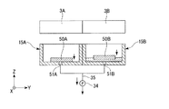
図3は、キャッピング機構15の構成を示す断面図である。
図1及び図3に示すように、キャップ部材15A及び15Bは、例えばY方向に並んで配置されている。キャリッジ5がホームポジションに配置された状態において、例えば噴射ヘッド3Aとキャップ部材15Aとが対向し、噴射ヘッド3Bとキャップ部材15Bとが対向するようになっている。
FIG. 3 is a cross-sectional view showing the configuration of the
As shown in FIGS. 1 and 3, the
図3に示すように、キャップ部材15A及びキャップ部材15Bは、上記のインクを受けるように凹状に形成されている。キャップ部材15A及び15Bは、それぞれ底部にインクの流出口51A及び51Bを有している。また、キャップ部材15A及び15Bの底部は、流出口51A及び51Bに重なるように閉塞部材50A及び50Bがそれぞれ配置されている。
As shown in FIG. 3, the
閉塞部材50A及び50Bは、例えばインクに対して浮くような材料を用いて形成されている。また、例えば閉塞部材50A及び50Bは、キャップ部材15A及び15Bの凹部内においてXY方向に移動した場合であっても流出口51A及び51Bに重なることができる程度の寸法に形成されている。図3では、キャップ部材15A及び15Bには、インクが存在しない状態を示している。このような場合においては、閉塞部材50A及び50Bによって流出口51A及び51Bが塞がれた状態になっている。
The
流出口51A及び51Bには、例えばチューブ部材35が接続されている。チューブ部材35は、一端が吸引ポンプ34に接続されている。チューブ部材35の他端は2つに分岐されており、その一方が流出口51Aに接続され、他方が流出口51Bに接続されている。このため、1つの吸引ポンプ34に対して流出口51A及び51Bの両方が接続されていることになる。
For example, a
次に、上述の構成を有するインクジェットプリンタ1の動作の一例を説明する。 Next, an example of the operation of the inkjet printer 1 having the above configuration will be described.
外部から印刷データが送信されると、不図示の制御装置は、ドットパターンに対応した噴射データに展開して噴射ヘッド3A及び3Bに送信する。噴射ヘッド3A及び3Bでは、受信した噴射データに基づき、記録(印字・印刷)処理、すなわち記録紙に対するインク滴の噴射を実行する。 When print data is transmitted from the outside, a control device (not shown) develops the ejection data corresponding to the dot pattern and transmits the ejection data to the ejection heads 3A and 3B. The ejection heads 3A and 3B execute recording (printing / printing) processing, that is, ejection of ink droplets onto recording paper, based on the received ejection data.
このような記録処理の後、動作を継続すると判断した場合、例えば予め設定されている時間が経過すると、定期メンテナンス処理を開始する。また、記録処理の後、動作を継続しないと判断した場合、インクジェットプリンタ1の処理を終了する。以下、動作を継続すると判断した場合について説明する。 When it is determined that the operation is continued after such a recording process, for example, when a preset time has elapsed, the periodic maintenance process is started. If it is determined that the operation is not continued after the recording process, the process of the inkjet printer 1 is terminated. Hereinafter, a case where it is determined that the operation is continued will be described.
本実施形態では、メンテナンス処理のうち、例えばフラッシング処理を行う場合を説明する。制御装置CONTは、噴射ヘッド3A及び3Bをホームポジションまで移動させる。この動作により、噴射ヘッド3Aとキャップ部材15Aとが対向し、噴射ヘッド3Bとキャップ部材15Bとが対向する。
In the present embodiment, a case in which, for example, a flushing process is performed in the maintenance process will be described. The control device CONT moves the ejection heads 3A and 3B to the home position. By this operation, the
この状態で、制御装置CONTは、図4に示すように、噴射ヘッド3A及び3BからインクQを排出させる。排出されたインクQは、キャップ部材15A及び15Bの凹部にそれぞれ収容される。本実施形態では、例えば噴射ヘッド3Aよりも噴射ヘッド3Bの方がインクQの排出量が多くなっている。
In this state, the control device CONT discharges the ink Q from the ejection heads 3A and 3B as shown in FIG. The discharged ink Q is accommodated in the recesses of the
図5は、キャップ部材15A及び15BにインクQが受けられた状態を示している。図5に示すように、キャップ部材15A及び15B内にインクQが収容されることにより、閉塞部材50A及び50BがインクQに浮上する。このため、流出口51A及び51Bと閉塞部材50A及び50Bとの間には、インクQが介在することになる。噴射ヘッド3Aよりも噴射ヘッド3Bの方がインクQの排出量が多いため、キャップ部材15Bの方がキャップ部材15AよりもインクQの液面が高くなっている。
FIG. 5 shows a state in which the ink Q is received by the
この状態で、制御装置CONTは、例えば吸引ポンプ34を駆動させる。この動作により、流出口51A及び51Bが吸引され、キャップ部材15A及びキャップ部材15Bに収容されるインクQが当該流出口51A及び51Bからそれぞれ流出する。流出したインクQは、チューブ部材35を介して外部に排出される。
In this state, the control device CONT drives the
本実施形態では、キャップ部材15Aに収容されたインクQの量がキャップ部材15Bに収容されたインクQの量よりも少ないため、吸引動作が進むと、図6に示すように、先にキャップ部材15A内のインクQが全て流出する。インクQが全て流出すると、閉塞部材50Aがキャップ部材15Aの底部に接触し、当該閉塞部材50Aによって流出口51Aが塞がれることになる。このため、キャップ部材15A内のインクQが全て流出した後は、キャップ部材15A側の吸引漏れが発生することなく、キャップ部材15Bの流出口51Bのみの吸引が行われることになる。
In the present embodiment, since the amount of the ink Q stored in the
なお、流出口51A及び51Bを吸引する際には、例えば図7に示すように、一旦閉塞部材50A及び50Bを浮かせた後、キャップ部材15A及び15Bによって噴射ヘッド3A及び3Bのノズル面3F及び3Gを覆った状態で吸引を行うようにしても構わない。この場合、キャップ部材15A及び15B内の液面の移動により、キャップ部材15A及び15Bとノズル面3F及び3Gとの間に負圧が発生する。当該負圧によってノズルNZからインクを排出させることができるため、ノズルNZの状態を保持することができる。
When suctioning the
また、例えば工場出荷時において、キャップ部材15A及び15B内にインクなどの液体を収容させ閉塞部材50A及び50Bを浮上させた状態にしておくようにしても構わない。この場合、インクカートリッジ6A及び6Bから噴射ヘッド3A及び3Bに対してインクQを初期充填する際には、キャップ部材15A及び15Bによって噴射ヘッド3A及び3Bのノズル面3F及び3Gを密閉し、吸引ポンプ34を作動させる。この動作により、予め収容しておいた液体が流出口51A及び51Bから流出すると共に、液面の低下によってキャップ部材15A及び15B内に負圧が発生し、当該負圧によってインクQを噴射ヘッド3A及び3B内に充填させることができる。
Further, for example, at the time of factory shipment, the
以上のように、本実施形態によれば、キャップ部材15A及びキャップ部材15Bのうち例えば一方にインクQが存在しない場合には、閉塞部材50A又は50Bによって流出口51A又は51Bが塞がれることになるため、一の吸引ポンプ34によって複数の流出口51A及び51Bを共通して吸引する場合でも、吸引漏れを防ぐことができる。これにより、流出口51A及び51Bごとに吸引ポンプ34を個別に設けなくても済むため、低コスト化を図ることができる。
As described above, according to the present embodiment, when the ink Q is not present in one of the
[第2実施形態]
次に、本発明の第2実施形態を説明する。図8は、本実施形態に係るキャッピング機構115の構成を示す図である。
図8に示すように、キャッピング機構115は、キャップ部材115A及びキャップ部材115Bを有している。キャップ部材115A及び115Bは、第1実施形態に記載のキャップ部材と同一の構成となっている。
[Second Embodiment]
Next, a second embodiment of the present invention will be described. FIG. 8 is a diagram illustrating a configuration of the
As shown in FIG. 8, the
本実施形態では、流出口151A及び151Bに対してチューブ部材135A及び135Bが接続されている。チューブ部材135A及び135Bは、チューブ部材135Cに接続されており、チューブ部材135Cには吸引ポンプ134が取り付けられている。このため、1つの吸引ポンプ134に対して流出口151A及び151Bの両方が接続されていることになる。
In this embodiment,
また、本実施形態では、チューブ部材135A及び135Bのそれぞれに対して、開閉バルブVA及びVBが取り付けられている。開閉バルブVA及びVBは、キャップ部材15A及び15Bが噴射ヘッド3A及び3Bのノズル面3F及び3Gを覆った状態において、それぞれ制御装置CONTによって個別に開閉が切り替えられるようになっている。
In the present embodiment, on-off valves VA and VB are attached to the
次に、フラッシング処理を行う場合を説明する。制御装置CONTは、噴射ヘッド3A及び3Bをホームポジションまで移動させ、噴射ヘッド3Aとキャップ部材115Aとを対向させると共に、噴射ヘッド3Bとキャップ部材115Bとを対向させる。
Next, a case where the flushing process is performed will be described. The control device CONT moves the ejection heads 3A and 3B to the home position, makes the
この状態で、制御装置CONTは、噴射ヘッド3A及び3BからインクQを排出させる。排出されたインクQは、キャップ部材115A及び115Bの凹部にそれぞれ収容される。本実施形態では、第1実施形態と同様、例えば噴射ヘッド3Aよりも噴射ヘッド3Bの方がインクQの排出量が多くした場合を例に挙げて説明する。
In this state, the control device CONT discharges the ink Q from the ejection heads 3A and 3B. The discharged ink Q is accommodated in the recesses of the
図9は、キャップ部材115A及び115BにインクQが受けられた状態を示している。本実施形態においても、噴射ヘッド3Aよりも噴射ヘッド3Bの方がインクQの排出量が多いため、キャップ部材115Bの方がキャップ部材115AよりもインクQの液面が高くなっている。
FIG. 9 shows a state in which the ink Q is received by the
この状態で、制御装置CONTは、例えば吸引ポンプ134を駆動させる。この動作により、流出口151A及び151Bが吸引され、キャップ部材115A及びキャップ部材115Bに収容されるインクQが当該流出口151A及び151Bからそれぞれ流出する。流出したインクQは、チューブ部材135を介して外部に排出される。
In this state, the control device CONT drives the
本実施形態では、キャップ部材115Aに収容されたインクQの量がキャップ部材115Bに収容されたインクQの量よりも少ないため、吸引動作が進むと、先にキャップ部材15A内のインクQが全て流出する。これに対して、制御装置CONTは、例えば図10に示すようにキャップ部材115A及びキャップ部材115Bを噴射ヘッド3A及び3Bのノズル面3F及び3Gに当接させ、この状態で流出口151Aに接続されるチューブ部材135Aの開閉バルブVAを閉状態にする。このため、キャップ部材115A内のインクQが全て流出した後は、キャップ部材115A側の吸引漏れが発生することなく、キャップ部材115Bの流出口151Bのみの吸引が行われることになる。
In this embodiment, since the amount of ink Q stored in the
以上のように、本実施形態では、ノズル面3F及び3Gが複数のキャップ部材115A及び115Bよって覆われ、かつ、少なくともキャップ部材115AのインクQが全て流出された状態において、当該キャップ部材115Aの流出口151Aが閉塞されることになるため、一の吸引ポンプ134によって流出口151A及び151Bを共通して吸引する場合でも、吸引漏れを防ぐことができる。これにより、流出口151A及び151Bごとに吸引ポンプ134を個別に設けなくても済むため、低コスト化を図ることができる。
As described above, in the present embodiment, the nozzle surfaces 3F and 3G are covered with the plurality of
本発明の技術範囲は上記実施形態に限定されるものではなく、本発明の趣旨を逸脱しない範囲で適宜変更を加えることができる。
例えば、上記実施形態においては、ヘッド部3が2つの噴射ヘッド3A及び3Bを有する構成としたが、これに限られることは無く、例えば1つの噴射ヘッドを有する構成であっても構わないし、3つ以上の噴射ヘッドを有する構成であっても構わない。また、ヘッド部3が1つの噴射ヘッドを有する構成とした場合、当該1つの噴射ヘッドに複数の噴射領域を配置させる構成としても構わない。
The technical scope of the present invention is not limited to the above-described embodiment, and appropriate modifications can be made without departing from the spirit of the present invention.
For example, in the above-described embodiment, the head unit 3 includes the two ejection heads 3A and 3B. However, the configuration is not limited thereto, and for example, the configuration may include one ejection head. A configuration having two or more ejection heads may be used. Further, when the head unit 3 has a configuration having one ejection head, a configuration may be adopted in which a plurality of ejection regions are arranged in the one ejection head.
上記の説明では、インクジェット式のプリンタと、インクカートリッジが採用されているが、インク以外の他の流体を噴射したり吐出したりする流体噴射装置と、その流体を収容した流体容器を採用しても良い。微小量の液滴を吐出させる流体噴射ヘッド等を備える各種の流体噴射装置に流用可能である。なお、液滴とは、上記流体噴射装置から吐出される流体の状態をいい、粒状、涙状、糸状に尾を引くものも含むものとする。また、ここでいう流体とは、流体噴射装置が噴射させることができるような材料であれ良い。 In the above description, an ink jet printer and an ink cartridge are employed. However, a fluid ejecting apparatus that ejects or ejects fluid other than ink and a fluid container that contains the fluid are employed. Also good. The present invention can be applied to various fluid ejecting apparatuses including a fluid ejecting head that ejects a minute amount of liquid droplets. In addition, a droplet means the state of the fluid discharged from the said fluid ejecting apparatus, and includes what pulls a tail in granular shape, tear shape, and thread shape. Moreover, the fluid here may be a material that can be ejected by the fluid ejecting apparatus.
例えば、物質が液相であるときの状態のものであれば良く、粘性の高い又は低い液状態、ゾル、ゲル水、その他の無機溶剤、有機溶剤、溶液、液状樹脂、液状金属(金属融液)のような流状態、また物質の一状態としての流体のみならず、顔料や金属粒子などの固形物からなる機能材料の粒子が溶媒に溶解、分散または混合されたものなどを含む。また、流体の代表的な例としては上記実施例の形態で説明したようなインクや液晶等が挙げられる。ここで、インクとは一般的な水性インクおよび油性インク並びにジェルインク、ホットメルトインク等の各種流体組成物を包含するものとする。 For example, it may be in the state when the substance is in a liquid phase, and may be in a liquid state with high or low viscosity, sol, gel water, other inorganic solvents, organic solvents, solutions, liquid resins, liquid metals (metal melts) ) And a fluid as one state of the substance, as well as particles in which functional material particles made of solid substances such as pigments and metal particles are dissolved, dispersed or mixed in a solvent. In addition, typical examples of the fluid include ink and liquid crystal as described in the embodiment. Here, the ink includes general water-based inks and oil-based inks, and various fluid compositions such as gel inks and hot-melt inks.
流体噴射装置の具体例としては、例えば液晶ディスプレイ、EL(エレクトロルミネッセンス)ディスプレイ、面発光ディスプレイ、カラーフィルタの製造などに用いられる電極材や色材などの材料を分散または溶解のかたちで含む流体を噴射する流体噴射装置、バイオチップ製造に用いられる生体有機物を噴射する流体噴射装置、精密ピペットとして用いられ試料となる流体を噴射する流体噴射装置、捺染装置やマイクロディスペンサ等であってもよい。 As a specific example of the fluid ejecting apparatus, for example, a fluid containing a material such as an electrode material or a color material used for manufacturing a liquid crystal display, an EL (electroluminescence) display, a surface emitting display, or a color filter in a dispersed or dissolved form. It may be a fluid ejecting apparatus for ejecting, a fluid ejecting apparatus for ejecting a bio-organic matter used for biochip manufacturing, a fluid ejecting apparatus for ejecting a fluid used as a precision pipette, a printing apparatus, a microdispenser, or the like.
さらに、時計やカメラ等の精密機械にピンポイントで潤滑油を噴射する流体噴射装置、光通信素子等に用いられる微小半球レンズ(光学レンズ)などを形成するために紫外線硬化樹脂等の透明樹脂液を基板上に噴射する流体噴射装置、基板などをエッチングするために酸又はアルカリ等のエッチング液を噴射する流体噴射装置を採用しても良い。そして、これらのうちいずれか一種の噴射装置および流体容器に本発明を適用することができる。 In addition, transparent resin liquids such as UV curable resins to form fluid injection devices that inject lubricating oil onto precision machines such as watches and cameras, micro hemispherical lenses (optical lenses) used in optical communication elements, etc. Alternatively, a fluid ejecting apparatus that ejects a liquid onto the substrate or a fluid ejecting apparatus that ejects an etching solution such as acid or alkali to etch the substrate may be employed. The present invention can be applied to any one of these ejecting apparatuses and fluid containers.
BD…プリンタ本体 IJ…インク噴射機構 MN…メンテナンス機構 CONT…制御装置 NZ…ノズル Q…インク 1…インクジェットプリンタ 3…ヘッド部 3A、3B…噴射ヘッド 3F、3G…ノズル面 3S、3T…液体噴射領域 15、115…キャッピング機構 15A、15B、115A、115B…キャップ部材 34、134…吸引ポンプ 50A、50B…閉塞部材 51A、51B、151A、151B…流出口 135A、135B、135C…チューブ部材 VA、VB…開閉バルブ
BD: Printer main body IJ: Ink ejection mechanism MN ... Maintenance mechanism CONT ... Control device NZ ... Nozzle Q ... Ink 1 ... Inkjet printer 3 ...
Claims (4)
前記ヘッド部から排出された前記液体を受けると共に、底部に前記液体の流出口が設けられた複数の液体受部と、
複数の前記液体受部のそれぞれの前記流出口に接続され、前記流出口を吸引する一の吸引ポンプと、
複数の前記液体受部にそれぞれ設けられ、前記液体に浮くように形成されると共に前記液体受部内の前記液体が流出された状態において前記流出口を閉塞する閉塞部材と
を備え、
複数の前記液体受部のそれぞれの前記閉塞部材が該液体受部内の前記液体に浮いた状態で、前記吸引ポンプを駆動し、いずれかの前記閉塞部材が前記流出口を閉塞した後も該吸引ポンプの駆動を継続することを特徴とする液体噴射装置。 A head for ejecting liquid;
Receiving the liquid discharged from the head portion, and a plurality of liquid receiving portions provided with a liquid outlet at the bottom;
A suction pump connected to the outlet of each of the plurality of liquid receiving portions and sucking the outlet;
A closing member provided in each of the plurality of liquid receiving portions, formed so as to float on the liquid, and closing the outlet in a state where the liquid in the liquid receiving portion has flowed out,
The suction pump is driven in a state where each of the closing members of the plurality of liquid receiving portions floats on the liquid in the liquid receiving portions, and the suction is performed even after any of the closing members closes the outlet. A liquid ejecting apparatus that continues to drive a pump.
複数の前記液体受部のそれぞれの前記閉塞部材が該液体受部内の前記液体に浮いた状態で、該液体受部で前記液体噴射領域を覆い、前記吸引ポンプを駆動することを特徴とする請求項1に記載の液体噴射装置。 The liquid receiving part is formed so as to cover a liquid ejecting region that ejects the liquid of the ejecting head part,
The liquid receiving unit covers the liquid ejecting area and drives the suction pump in a state where each of the closing members of the plurality of liquid receiving units floats on the liquid in the liquid receiving unit. Item 2. The liquid ejecting apparatus according to Item 1.
前記液体受部は、前記液体噴射領域毎に設けられている
請求項1に記載の液体噴射装置。 The head portion has a plurality of the liquid ejecting regions,
The liquid ejecting apparatus according to claim 1, wherein the liquid receiving unit is provided for each liquid ejecting region.
前記液体噴射領域は、前記噴射ヘッド毎に設けられている
請求項3に記載の液体噴射装置。 The head portion has a plurality of ejection heads,
The liquid ejecting apparatus according to claim 3, wherein the liquid ejecting region is provided for each of the ejecting heads.
Priority Applications (3)
| Application Number | Priority Date | Filing Date | Title |
|---|---|---|---|
| JP2010028877A JP5751460B2 (en) | 2010-02-12 | 2010-02-12 | Liquid ejector |
| US13/026,198 US8480204B2 (en) | 2010-02-12 | 2011-02-11 | Liquid ejecting apparatus |
| CN201110036440.9A CN102161274B (en) | 2010-02-12 | 2011-02-12 | Liquid ejecting apparatus |
Applications Claiming Priority (1)
| Application Number | Priority Date | Filing Date | Title |
|---|---|---|---|
| JP2010028877A JP5751460B2 (en) | 2010-02-12 | 2010-02-12 | Liquid ejector |
Publications (3)
| Publication Number | Publication Date |
|---|---|
| JP2011161854A JP2011161854A (en) | 2011-08-25 |
| JP2011161854A5 JP2011161854A5 (en) | 2013-03-07 |
| JP5751460B2 true JP5751460B2 (en) | 2015-07-22 |
Family
ID=44369372
Family Applications (1)
| Application Number | Title | Priority Date | Filing Date |
|---|---|---|---|
| JP2010028877A Active JP5751460B2 (en) | 2010-02-12 | 2010-02-12 | Liquid ejector |
Country Status (3)
| Country | Link |
|---|---|
| US (1) | US8480204B2 (en) |
| JP (1) | JP5751460B2 (en) |
| CN (1) | CN102161274B (en) |
Families Citing this family (5)
| Publication number | Priority date | Publication date | Assignee | Title |
|---|---|---|---|---|
| JP6354199B2 (en) * | 2014-02-24 | 2018-07-11 | ブラザー工業株式会社 | Liquid ejection device |
| DE112015004380B4 (en) | 2014-09-25 | 2018-06-28 | Fujifilm Corporation | WIPE MECHANISM, LIQUID STAINLESS STEEL DEVICE AND WIPING METHOD |
| CN104862685B (en) * | 2015-04-23 | 2017-06-16 | 西安四方超轻材料有限公司 | A kind of magnesium lithium alloy surface processing device |
| JP6897152B2 (en) * | 2017-02-27 | 2021-06-30 | セイコーエプソン株式会社 | Liquid injection device |
| JP6938185B2 (en) | 2017-03-23 | 2021-09-22 | 東芝テック株式会社 | Maintenance equipment and liquid discharge equipment |
Family Cites Families (8)
| Publication number | Priority date | Publication date | Assignee | Title |
|---|---|---|---|---|
| US6364449B1 (en) * | 1998-09-16 | 2002-04-02 | Seiko Epson Corporation | Ink jet recording apparatus and cleaning control method for the same |
| JP3981502B2 (en) | 1998-09-16 | 2007-09-26 | セイコーエプソン株式会社 | Ink jet recording apparatus and cleaning method suitable therefor |
| EP2228220B1 (en) * | 2003-03-18 | 2012-07-04 | Seiko Epson Corporation | Liquid ejecting apparatus |
| JP2005288740A (en) * | 2004-03-31 | 2005-10-20 | Seiko Epson Corp | Cleaning method of liquid ejector and liquid ejector |
| JP4810293B2 (en) * | 2006-04-28 | 2011-11-09 | キヤノン株式会社 | Suction method and ink jet recording apparatus |
| JP4942494B2 (en) * | 2007-01-24 | 2012-05-30 | 株式会社リコー | Image forming apparatus |
| JP2009143161A (en) * | 2007-12-17 | 2009-07-02 | Seiko Epson Corp | Liquid processing device and inkjet recording apparatus having the same |
| JP2009172789A (en) * | 2008-01-22 | 2009-08-06 | Kyocera Mita Corp | Image forming apparatus |
-
2010
- 2010-02-12 JP JP2010028877A patent/JP5751460B2/en active Active
-
2011
- 2011-02-11 US US13/026,198 patent/US8480204B2/en active Active
- 2011-02-12 CN CN201110036440.9A patent/CN102161274B/en active Active
Also Published As
| Publication number | Publication date |
|---|---|
| US20110199427A1 (en) | 2011-08-18 |
| US8480204B2 (en) | 2013-07-09 |
| JP2011161854A (en) | 2011-08-25 |
| CN102161274A (en) | 2011-08-24 |
| CN102161274B (en) | 2015-02-11 |
Similar Documents
| Publication | Publication Date | Title |
|---|---|---|
| US9296216B2 (en) | Liquid ejecting apparatus and maintenance method thereof | |
| JP5211931B2 (en) | Fluid ejection device | |
| JP2012101476A (en) | Liquid ejection device | |
| JP5751460B2 (en) | Liquid ejector | |
| JP5668467B2 (en) | Liquid ejector | |
| JP5458600B2 (en) | Fluid ejection device | |
| JP2012061785A (en) | Liquid jetting device | |
| JP5663971B2 (en) | Fluid ejection device | |
| US8708454B2 (en) | Fluid ejecting apparatus | |
| JP5651997B2 (en) | Maintenance device and fluid ejection device | |
| JP2015116826A (en) | Liquid ejecting apparatus | |
| US8827421B2 (en) | Maintenance method for fluid ejecting apparatus and fluid ejecting apparatus | |
| JP5572950B2 (en) | Fluid ejection device | |
| JP5857748B2 (en) | Liquid ejector | |
| JP2019093618A (en) | Liquid jet device | |
| JP5499883B2 (en) | Fluid ejection device | |
| JP2010167606A (en) | Fluid discharging device | |
| JP2010228118A (en) | Method for maintaining fluid jet device and fluid jet device | |
| JP2011183766A (en) | Liquid ejector | |
| JP2010167604A (en) | Fluid injection device | |
| JP2011255620A (en) | Liquid ejection apparatus | |
| JP2010167602A (en) | Fluid discharging device | |
| JP2011093194A (en) | Fluid jetting apparatus and maintenance method | |
| JP2012136004A (en) | Liquid ejecting apparatus | |
| JP2010036496A (en) | Fluid jet device and fluid jet method |
Legal Events
| Date | Code | Title | Description |
|---|---|---|---|
| RD04 | Notification of resignation of power of attorney |
Free format text: JAPANESE INTERMEDIATE CODE: A7424 Effective date: 20120202 |
|
| A521 | Written amendment |
Free format text: JAPANESE INTERMEDIATE CODE: A523 Effective date: 20130116 |
|
| A621 | Written request for application examination |
Free format text: JAPANESE INTERMEDIATE CODE: A621 Effective date: 20130116 |
|
| A977 | Report on retrieval |
Free format text: JAPANESE INTERMEDIATE CODE: A971007 Effective date: 20131031 |
|
| A131 | Notification of reasons for refusal |
Free format text: JAPANESE INTERMEDIATE CODE: A131 Effective date: 20131105 |
|
| A521 | Written amendment |
Free format text: JAPANESE INTERMEDIATE CODE: A523 Effective date: 20131226 |
|
| A131 | Notification of reasons for refusal |
Free format text: JAPANESE INTERMEDIATE CODE: A131 Effective date: 20140902 |
|
| A521 | Written amendment |
Free format text: JAPANESE INTERMEDIATE CODE: A523 Effective date: 20141104 |
|
| TRDD | Decision of grant or rejection written | ||
| A01 | Written decision to grant a patent or to grant a registration (utility model) |
Free format text: JAPANESE INTERMEDIATE CODE: A01 Effective date: 20150424 |
|
| A61 | First payment of annual fees (during grant procedure) |
Free format text: JAPANESE INTERMEDIATE CODE: A61 Effective date: 20150507 |
|
| R150 | Certificate of patent or registration of utility model |
Ref document number: 5751460 Country of ref document: JP Free format text: JAPANESE INTERMEDIATE CODE: R150 |
|
| S531 | Written request for registration of change of domicile |
Free format text: JAPANESE INTERMEDIATE CODE: R313531 |
|
| R350 | Written notification of registration of transfer |
Free format text: JAPANESE INTERMEDIATE CODE: R350 |