JP5749090B2 - Inhaler - Google Patents
Inhaler Download PDFInfo
- Publication number
- JP5749090B2 JP5749090B2 JP2011132173A JP2011132173A JP5749090B2 JP 5749090 B2 JP5749090 B2 JP 5749090B2 JP 2011132173 A JP2011132173 A JP 2011132173A JP 2011132173 A JP2011132173 A JP 2011132173A JP 5749090 B2 JP5749090 B2 JP 5749090B2
- Authority
- JP
- Japan
- Prior art keywords
- housing
- detection wall
- inhaler
- detection
- main part
- Prior art date
- Legal status (The legal status is an assumption and is not a legal conclusion. Google has not performed a legal analysis and makes no representation as to the accuracy of the status listed.)
- Active
Links
- 238000001514 detection method Methods 0.000 claims description 71
- 238000006073 displacement reaction Methods 0.000 claims description 7
- 230000008878 coupling Effects 0.000 claims description 5
- 238000010168 coupling process Methods 0.000 claims description 5
- 238000005859 coupling reaction Methods 0.000 claims description 5
- 229940071648 metered dose inhaler Drugs 0.000 description 5
- 238000000034 method Methods 0.000 description 5
- 230000004913 activation Effects 0.000 description 4
- 239000000463 material Substances 0.000 description 4
- 238000007599 discharging Methods 0.000 description 2
- 238000004146 energy storage Methods 0.000 description 2
- 239000007788 liquid Substances 0.000 description 2
- 210000004072 lung Anatomy 0.000 description 2
- 239000012528 membrane Substances 0.000 description 2
- 230000002093 peripheral effect Effects 0.000 description 2
- 238000004804 winding Methods 0.000 description 2
- 230000004308 accommodation Effects 0.000 description 1
- 230000002411 adverse Effects 0.000 description 1
- 230000000994 depressogenic effect Effects 0.000 description 1
- 229940079593 drug Drugs 0.000 description 1
- 239000003814 drug Substances 0.000 description 1
- 239000012530 fluid Substances 0.000 description 1
- 238000003780 insertion Methods 0.000 description 1
- 230000037431 insertion Effects 0.000 description 1
- 238000004519 manufacturing process Methods 0.000 description 1
- 230000013011 mating Effects 0.000 description 1
- 239000000203 mixture Substances 0.000 description 1
- 208000023504 respiratory system disease Diseases 0.000 description 1
Images

Classifications
-
- A—HUMAN NECESSITIES
- A61—MEDICAL OR VETERINARY SCIENCE; HYGIENE
- A61M—DEVICES FOR INTRODUCING MEDIA INTO, OR ONTO, THE BODY; DEVICES FOR TRANSDUCING BODY MEDIA OR FOR TAKING MEDIA FROM THE BODY; DEVICES FOR PRODUCING OR ENDING SLEEP OR STUPOR
- A61M15/00—Inhalators
- A61M15/009—Inhalators using medicine packages with incorporated spraying means, e.g. aerosol cans
-
- A—HUMAN NECESSITIES
- A61—MEDICAL OR VETERINARY SCIENCE; HYGIENE
- A61M—DEVICES FOR INTRODUCING MEDIA INTO, OR ONTO, THE BODY; DEVICES FOR TRANSDUCING BODY MEDIA OR FOR TAKING MEDIA FROM THE BODY; DEVICES FOR PRODUCING OR ENDING SLEEP OR STUPOR
- A61M15/00—Inhalators
- A61M15/0065—Inhalators with dosage or measuring devices
- A61M15/0068—Indicating or counting the number of dispensed doses or of remaining doses
- A61M15/008—Electronic counters
Landscapes
- Health & Medical Sciences (AREA)
- Engineering & Computer Science (AREA)
- Life Sciences & Earth Sciences (AREA)
- Anesthesiology (AREA)
- Pulmonology (AREA)
- Biomedical Technology (AREA)
- Heart & Thoracic Surgery (AREA)
- Hematology (AREA)
- Bioinformatics & Cheminformatics (AREA)
- Animal Behavior & Ethology (AREA)
- General Health & Medical Sciences (AREA)
- Public Health (AREA)
- Veterinary Medicine (AREA)
- Biophysics (AREA)
- Containers And Packaging Bodies Having A Special Means To Remove Contents (AREA)
- Infusion, Injection, And Reservoir Apparatuses (AREA)
Description
本発明は、薬剤媒体の経口投与のための吸入器に関する。かかるタイプの一般的な吸入器は、マウスピースを含むハウジング;ハウジングの吸入領域内に収容され、かつ媒体容器、及び出口オリフィスを持つ出口連結器を含む容器ユニットであって、この連結器が、排出操作を実行する目的のために媒体容器に対して変位されることができるもの;及び媒体の排出を検出するための排出センサを含む。 The present invention relates to an inhaler for oral administration of a pharmaceutical medium. A common inhaler of this type is a housing that includes a mouthpiece; a container unit that is contained in the inhalation region of the housing and includes a media container and an outlet connector having an outlet orifice, the connector comprising: One that can be displaced relative to the media container for the purpose of performing a discharge operation; and a discharge sensor for detecting the discharge of the medium.
一般的な吸入器は通常、MDI(定量吸入器)及びpMDI(加圧定量吸入器)と呼ばれる。それらは、呼吸疾患を治療する目的のために使用者の肺中に噴霧形態で移されることを意図されている薬剤を投与するために使用される。それらは、前述の容器ユニットを内部に挿入して含むハウジングを含む。ハウジングは、ハウジングの吸入領域を通してマウスピースに向けて空気が吸い込まれることを可能にする空気取入れ口を含む。空気が吸い込まれると同時に、媒体容器を出口連結器に対して変位することにより媒体が媒体容器から排出され、従って吸い込まれた空気が噴霧された媒体と混合して肺中に移るように吸入される。 Common inhalers are usually called MDI (metered dose inhaler) and pMDI (pressure metered dose inhaler). They are used to administer drugs that are intended to be transferred in nebulized form into the lungs of the user for the purpose of treating respiratory diseases. They include a housing containing the aforementioned container unit inserted therein. The housing includes an air intake that allows air to be drawn into the mouthpiece through the suction area of the housing. At the same time that air is inhaled, the media container is displaced from the media container by displacing the media container with respect to the outlet coupler, so that the inhaled air is inhaled so that it mixes with the nebulized medium and moves into the lungs. The
媒体は、出口連結器に対して媒体容器を変位することにより媒体容器から排出される。最も簡単な場合、一般的な吸入器の媒体容器は、この目的のためにハウジングの空気取入れ口からある範囲まで突き出ることができ、従ってそれは、ハウジングのかみ合い凹所内に挿入された出口連結器に対して変位されるために直接手動力を受けさせることができる。 Media is ejected from the media container by displacing the media container relative to the outlet coupler. In the simplest case, the media container of a common inhaler can protrude to a certain extent from the housing air intake for this purpose, so that it is connected to an outlet connector inserted in the mating recess of the housing. In contrast, it can be directly subjected to manual force to be displaced.
一般的な吸入器は、排出操作を検出するために、特に排出操作を数える目的のために排出センサを備えている。これは、使用者が媒体容器内にまだ残っている媒体の投与数を知ることを可能にし、従って媒体容器内の媒体がどのくらい長く持続するかを見積もることを可能にする。 A typical inhaler is equipped with a discharge sensor in order to detect the discharge operation, in particular for the purpose of counting the discharge operation. This allows the user to know the number of doses of media still remaining in the media container, and thus to estimate how long the media in the media container will last.
排出センサを設計する種々の方法が従来技術で知られている。 Various methods for designing an exhaust sensor are known in the prior art.
WO1997/033640A1は、媒体を排出するために設けられた通路内に配置されかつ媒体の排出を検出することを可能にする圧力センサを記載する。この設計は比較的複雑でかつ高価である。 WO 1997/033640 A1 describes a pressure sensor which is arranged in a passage provided for discharging a medium and which can detect the discharge of the medium. This design is relatively complex and expensive.
WO1991/0006334A1は、排出操作がハウジングの吸入領域内の媒体容器の動きを感知することにより機械的に検出される設計を開示する。それに匹敵する解決策はWO1996/000595A1に開示されている。WO2005/009325A2はまた、多数の実施態様を記載し、それらの殆どが、ハウジングの吸入領域内に配置されかつ吸入領域内の媒体容器の変位時に作動されるプッシュボタンを設けている。さらに、この文献はまた、プッシュボタンがハウジングの外表面上に設けられることができることを開示し、このプッシュボタンは、媒体容器をハウジングに対して動かすために力が手動で付与されるときに必然的に作動される。 WO 1991/0006334 A1 discloses a design in which the ejection operation is mechanically detected by sensing the movement of the media container in the suction area of the housing. A comparable solution is disclosed in WO 1996 / 000595A1. WO 2005/009325 A2 also describes a number of embodiments, most of which are provided with a push button which is arranged in the suction area of the housing and which is activated upon displacement of the media container in the suction area. In addition, this document also discloses that a push button can be provided on the outer surface of the housing, which is inevitable when force is manually applied to move the media container relative to the housing. Actuated automatically.
吸入領域内の媒体容器の動きを直接検出するプッシュボタンを含む実施態様の不利は、それらが媒体の排出の信頼性ある検出を保証しないことが多いことである。なぜならハウジングの内部内の容器ユニットの位置は、媒体容器がスイッチを過ぎて動かすことを可能にする許容誤差にさらされるからである。排出操作を検出することに対してもたらされる失敗は基本的に、実際に起こらなかった排出操作の間違った検出より重大であると見なされる。さらに、湿気に露出される結果としてプッシュボタン故障の危険がある。なぜならそれは吸入領域内に直接配置され、結果として排出操作が信頼性をもって検出されないからである。 A disadvantage of embodiments that include push buttons that directly detect movement of the media container within the inhalation region is that they often do not guarantee reliable detection of media ejection. This is because the position of the container unit within the interior of the housing is subject to tolerances that allow the media container to move past the switch. Failures that result in detecting a discharge operation are basically considered more serious than a false detection of a discharge operation that did not actually occur. Furthermore, there is a risk of push button failure as a result of exposure to moisture. This is because it is placed directly in the inhalation area and as a result, the discharge operation is not reliably detected.
本発明の目的は、排出操作を高い信頼性で検出できることを実現する一般的な吸入器を開発することである。それはさらに、吸入器のための費用効果的な設計を達成することを目的とする。 An object of the present invention is to develop a general inhaler that realizes that the discharge operation can be detected with high reliability. It is further aimed at achieving a cost effective design for the inhaler.
本発明によれば、この目的は、ハウジングが主要部と検出壁部を含み、この検出壁部が主要部に対して変位可能であり、かつそれが排出操作時にハウジングの主要部に対して変位されるように構成されかつ/または配置されることで達成される。さらに、排出センサは、ハウジングの主要部に対して検出壁部の変位を検出するように構成される。 According to the invention, the object is that the housing comprises a main part and a detection wall part, the detection wall part being displaceable relative to the main part, and it being displaced relative to the main part of the housing during the discharge operation. Achieved and / or arranged as such. Further, the discharge sensor is configured to detect the displacement of the detection wall portion with respect to the main portion of the housing.
従って、本発明によれば、吸入領域の範囲を定めかつ特に環境または電子要素を収容する部屋から分離する壁部が設けられ、またハウジングの主要部に対して動かされることができかつ媒体容器が吸入領域内で変位されるときに動く検出壁部が設けられる。この検出壁部の動きは排出センサにより検出され、それは媒体容器の動きを直接検出しない。 Thus, according to the present invention, a wall is provided that delimits the inhalation area and in particular separates from the environment or the room containing the electronic elements, and can be moved relative to the main part of the housing and the media container is A detection wall is provided that moves when displaced within the suction area. This movement of the detection wall is detected by the discharge sensor, which does not directly detect the movement of the media container.
本発明の吸入器は上述の一般的な吸入器の特徴を持つ。従って、それは、好ましくはプッシュボタンの形態である排出センサの信号を評価するように構成されている電子システムを含むことが好ましい。好ましくは、この電子システムは、特に排出操作を数えるために使用される集積回路を含む。さらに、それは、エネルギー貯蔵装置としての電池、及び既に排出されたかまたは媒体容器内になお存在する投与の数を表わすディスプレイの形態の出力ユニットを含むことが好ましい。 The inhaler of the present invention has the characteristics of the general inhaler described above. Accordingly, it preferably includes an electronic system configured to evaluate the signal of the discharge sensor, preferably in the form of a push button. Preferably, the electronic system includes an integrated circuit that is used specifically for counting the discharge operations. In addition, it preferably includes a battery as an energy storage device and an output unit in the form of a display representing the number of doses already drained or still present in the media container.
ハウジングの主要部(それに対して検出壁部が動かされることができる)は、吸入器の指定された使用に従って使用者により保持されるべきであるハウジングの外部表面の部分を含む。ハウジングの外部表面のこれらの部分は円筒状ハウジング部を含み、それは、容器ユニット、及びハウジングに対して不動であるマウスピースのようなハウジングの全要素を取り囲む。検出壁部は、この主要部に対して可動であり、かつそれが媒体容器への手動力の付与を必要とすることなく排出操作の完了でその出発位置に戻るような方式で主要部に連結されている。ハウジングの一部の形態である検出壁部は、好ましくは主要部と同じ材料から、特にプラスチック材料から作られる。好ましくは、検出壁部は、検出壁部を取り囲むハウジングの主要部の少なくともそれらの部分に一体的に連結される。主要部と検出壁部の間の連結領域は変形可能な性質のものである。主要部の部分への検出壁部のこの一体的連結は吸入器の製造を簡略化する。なぜなら検出壁部はハウジングの製造時に直接設けられることができるからである。さらに、この一体的連結は、連結領域の適切な弾性構造の使用により前述の検出壁部のその初期位置への自動復帰を達成する簡単な方式を提供する。さらに、一体的連結はまた、望ましい液密を達成することに関して利点がある。この目的のために、さらに、連結領域が検出壁部をその周囲周りで取り囲み、従って検出壁部を液密態様でハウジングの主要部に連結することがなされる。かかる場合、連結領域は検出壁部及び主要部の壁厚より有意に小さい壁厚を持つ領域の形態である。それは、変形の容易さを確実にするために一連の蛇腹式の折りたたみを持つことができる。上述の周囲連結領域を含む液密構成とは別に、検出壁部のハウジングの主要部への連結を別個の材料、特に材料の薄壁ブリッジにより確立することもまた可能である。 The main part of the housing (to which the detection wall can be moved) includes the part of the outer surface of the housing that should be held by the user according to the specified use of the inhaler. These portions of the outer surface of the housing include a cylindrical housing portion that surrounds the container unit and all elements of the housing, such as a mouthpiece that is immobile with respect to the housing. The detection wall is movable relative to this main part and is connected to the main part in such a way that it returns to its starting position upon completion of the discharge operation without the need to apply manual force to the media container. Has been. The detection wall in the form of a part of the housing is preferably made from the same material as the main part, in particular from a plastic material. Preferably, the detection wall portion is integrally connected to at least those portions of the main portion of the housing surrounding the detection wall portion. The connection area between the main part and the detection wall part is of a deformable nature. This integral connection of the detection wall to the main part simplifies the manufacture of the inhaler. This is because the detection wall can be provided directly when the housing is manufactured. Furthermore, this integral connection provides a simple way of achieving automatic return of the aforementioned detection wall to its initial position by using a suitable elastic structure of the connection region. Furthermore, the integral connection is also advantageous with respect to achieving the desired fluid tightness. For this purpose, it is further provided that the connection region surrounds the detection wall around its periphery, thus connecting the detection wall to the main part of the housing in a liquid-tight manner. In such a case, the connection region is in the form of a region having a wall thickness that is significantly smaller than the wall thickness of the detection wall portion and the main portion. It can have a series of bellows-type folds to ensure ease of deformation. Apart from the liquid-tight arrangement comprising the surrounding connection area described above, it is also possible to establish the connection of the detection wall to the main part of the housing by a separate material, in particular a thin wall bridge of material.
好ましくは、排出センサは、吸入領域から遠い検出壁部の側に設けられる。従って、それは保護された領域内に配置される。それゆえ、容器ユニットの挿入時に排出センサに与えられる損傷の危険がない。特に、上述の連結領域の液密構成はまた、吸入領域から遠い排出センサが吸入領域に存在する液体により有害な影響を受けないことを確実にする。 Preferably, the discharge sensor is provided on the side of the detection wall portion far from the suction area. It is therefore placed in the protected area. Therefore, there is no risk of damage to the discharge sensor when the container unit is inserted. In particular, the liquid-tight configuration of the connection area described above also ensures that the discharge sensor far from the suction area is not adversely affected by the liquid present in the suction area.
検出壁部は、容器ユニットがその移動またはその媒体容器の移動行程中に検出壁部に沿ってスライドしかつハウジングの主要部に対して検出壁部を偏向するような方式で容器ユニットと共働することができる。この偏向は排出センサにより検出される。しかし、検出壁部が容器ユニットの媒体容器または容器ユニットの出口連結器に対して不動であるという一実施態様も有利であると考えられる。かかる実施態様では、容器ユニットのハウジング中への挿入は、互いに対して可動である容器ユニットの二つの要素のいずれか一つが検出壁部に対して不動のままであるという状態をもたらす。これは、検出壁部とそれに対して不動である容器ユニットの要素との間の非常にしっかりとした共働を確実にする。検出壁部に対する容器ユニットの要素の不動性は、出口連結器と検出壁部の間の不確動または確動連結により達成されることができる。簡単なプラグとソケットの連結はこの目的のために十分であることができる。 The detection wall cooperates with the container unit in such a manner that the container unit slides along the detection wall during the movement or movement of the medium container and deflects the detection wall with respect to the main part of the housing. can do. This deflection is detected by a discharge sensor. However, an embodiment in which the detection wall is stationary with respect to the medium container of the container unit or the outlet connector of the container unit is also considered advantageous. In such an embodiment, insertion of the container unit into the housing results in the condition that one of the two elements of the container unit that are movable relative to each other remains immobile with respect to the detection wall. This ensures a very tight cooperation between the detection wall and the elements of the container unit that are stationary relative thereto. Immobility of the elements of the container unit relative to the detection wall can be achieved by an inaccurate or positive connection between the outlet coupler and the detection wall. A simple plug and socket connection can be sufficient for this purpose.
検出壁部が操作時に容器ユニットの出口連結器に対して不動のままであることは非常に好ましい。この目的のために、検出壁部が出口連結器の収容のための凹所、好ましくは通路を介して前記凹所に連結されている排出ノズルを含むとき特に好ましい。この排出ノズルは、ハウジングの吸入領域中に開口し、かつ媒体容器から来る媒体が吸入時に使用者により吸い込まれる空気と混合する領域を規定する。検出壁部が出口連結器に対して不動のままであるかかる実施態様では、検出壁部は使用時のMDIの通常の配向では容器ユニットの下に配置される。媒体容器がハウジングの主要部に対して押し下げられるとき、検出壁部はそれに応じてハウジングの主要部に対して同じ方向に、しかし少ない範囲で変位される。かかる実施態様は特に信頼性があることが立証された。なぜならそれは、例えばハウジング内の容器ユニットの位置に関しての許容誤差のために投与が間違って数えられるという状況、または実際に起こった作動が数えられないかまたは開始されたが液体が排出される前に早まって終了したという作動が数えられるという状況を防ぐからである。 It is highly preferred that the detection wall remains stationary with respect to the outlet coupler of the container unit during operation. For this purpose, it is particularly preferred when the detection wall comprises a recess for accommodating the outlet coupler, preferably a discharge nozzle connected to said recess via a passage. The discharge nozzle opens into the suction region of the housing and defines a region where the media coming from the media container mixes with the air that is inhaled by the user during suction. In such embodiments where the detection wall remains stationary with respect to the outlet coupler, the detection wall is placed under the container unit in the normal orientation of the MDI in use. When the media container is pushed down with respect to the main part of the housing, the detection wall is accordingly displaced in the same direction with respect to the main part of the housing, but to a lesser extent. Such an embodiment has proven to be particularly reliable. This is because, for example, a situation where the dose is incorrectly counted due to tolerances with respect to the position of the container unit within the housing, or the actual operation that has occurred is not counted or started but before the liquid is drained. This is to prevent a situation in which operations that have ended prematurely are counted.
好ましくは、排出センサ、検出壁部、及び容器ユニットは、ハウジングの主要部に対する容器ユニットの変位時に、検出壁部が媒体容器からの媒体を排出する操作が始まるとすぐに、またはその前に排出センサを作動するように互いに適合されかつ配置される。 Preferably, the discharge sensor, the detection wall and the container unit are discharged as soon as or before the operation of the detection wall discharging the medium from the medium container starts when the container unit is displaced relative to the main part of the housing. They are adapted and arranged with respect to each other to actuate the sensors.
これは、検出壁部により排出センサを起動するのに十分な範囲まで検出壁部の偏向を起こすために必要な力が、排出操作が始まるような範囲まで媒体容器に対して容器ユニットの出口連結器を変位するのに必要な力に等しいか、またはそれより小さいことを意味する。ハウジングに対して弾性的に偏向されることができる検出壁部が操作時に出口連結器に対して常に不動のままであるという前述の実施態様の場合では、媒体容器がハウジングの主要部に対して変位される距離は、媒体容器が出口連結器に対して変位される副距離と、出口連結器及び検出壁部がハウジングの主要部に対して変位される副距離に分割される。前述の挙動は、検出壁部が出口連結器を媒体容器に対して変位するために必要な力まで主要部に連結されるという態様に適切に適合することにより達成されることができる。 This is because the outlet of the container unit is connected to the medium container to the extent that the force required to cause the deflection of the detection wall to the extent sufficient to activate the discharge sensor by the detection wall starts to the discharge operation. Means less than or equal to the force required to displace the vessel. In the case of the aforementioned embodiment in which the detection wall that can be deflected elastically with respect to the housing always remains stationary with respect to the outlet coupler during operation, the media container is relative to the main part of the housing. The displaced distance is divided into a sub-distance where the media container is displaced relative to the outlet coupler and a sub-distance where the outlet coupler and detection wall are displaced relative to the main part of the housing. The aforementioned behavior can be achieved by appropriately adapting the manner in which the detection wall is connected to the main part up to the force required to displace the outlet coupler relative to the media container.
このタイプの適合は、排出操作が数えられるとき、例えばハウジングの主要部に対する媒体容器の不十分な変位からもたらされる不完全な排出操作がまた、排出センサにより記録されかつ許容されることを確実にする。従って、数える工程により決定されるとき、媒体容器内の媒体の残量の存在する媒体の実際の量からの偏差は、媒体容器内になお存在する媒体の量が過小評価されるときにこの方法で可能であるにすぎない。これは、実際にはもはや媒体が存在しないときに媒体容器内に媒体が残っていると推定される状況を防ぐ。 This type of fit ensures that when a discharge operation is counted, an incomplete discharge operation, for example resulting from insufficient displacement of the media container relative to the main part of the housing, is also recorded and allowed by the discharge sensor. To do. Thus, as determined by the counting process, the deviation of the remaining amount of media in the media container from the actual amount of media present is determined by this method when the amount of media still present in the media container is underestimated. It is only possible. This prevents situations where it is presumed that media will remain in the media container when there is no longer any media in practice.
好ましくはプッシュボタンの形態である排出センサは、特にハウジングの主要部上に設けられることができ、かつプッシュボタンのベースに対して変位されることができるプッシュボタンの表面が吸入器の作動時に検出壁部により押し下げられるような方式で配置されることができる。上述のように、排出センサは吸入領域から遠い検出壁部の側に配置されることが好ましい。ハウジングが結合装置により互いに結合されることができる二つの副ハウジングを含み、第一副ハウジングが吸入領域を取り囲みかつ検出壁部を含み、一方第二副ハウジングが排出センサを含むときに特に有利である。 The discharge sensor, preferably in the form of a push button, can be provided in particular on the main part of the housing and the surface of the push button which can be displaced relative to the base of the push button is detected during operation of the inhaler It can be arranged in such a way that it is pushed down by the wall. As described above, the discharge sensor is preferably disposed on the side of the detection wall that is far from the suction region. Particularly advantageous when the housing includes two sub-housings that can be coupled to each other by a coupling device, the first sub-housing enclosing the suction area and including the detection wall, while the second sub-housing includes an exhaust sensor. is there.
かかる実施態様では、第一副ハウジングはその使用後に容器ユニットと一緒に処分されることを意図されることができ、一方、排出センサ及び好ましくは吸入器の全ての他の電子要素を含む第二副ハウジングは再使用されるであろう。かかる場合、排出センサは、外力の付与がセンサを起動することができるような方式で第二副ハウジング内に配置され、この力の付与は副ハウジングの結合状態の適切に構成された検出壁部により実行される。 In such an embodiment, the first sub-housing can be intended to be disposed of with the container unit after its use, while the second sub-housing including the discharge sensor and preferably all other electronic components of the inhaler. The secondary housing will be reused. In such a case, the discharge sensor is arranged in the second sub-housing in such a way that the application of an external force can activate the sensor, and the application of this force is a suitably configured detection wall part of the combined state of the sub-housing. It is executed by.
二つの副ハウジングを含むこの実施態様の開発において、第二副ハウジングは、二つの副ハウジングの結合状態を検出するのに適合しているセンサを含む。これは別のセンサであることができる。排出センサはまた、第一に結合状態を検出し、第二に例えばプッシュボタン表面の偏向により示されるような検出壁部の変位を検出することができるように構成されることができる。 In the development of this embodiment including two sub-housings, the second sub-housing includes a sensor that is adapted to detect the coupling state of the two sub-housings. This can be another sensor. The ejection sensor can also be configured to detect firstly the coupling state and secondly to detect the displacement of the detection wall as indicated by, for example, the push button surface deflection.
好ましくは、電子要素、特に数える目的のために設けられた回路は、数える目的のために設けられたセンサの起動が副ハウジングが結合状態にあるときのみに投与を数えるために使用されるような方法で構成される。 Preferably, the electronic element, in particular the circuit provided for counting purposes, is such that activation of a sensor provided for counting purposes is used for counting dosing only when the secondary housing is in the coupled state. Composed of methods.
二つの副ハウジングを含むかかる実施態様では、非常に好ましくは第二副ハウジングは排出センサの領域内で変形可能または変位可能な壁部により境界付けられる内部領域を含む。これは、電子システムが完全に封入されることを可能にする。かかる場合及び副ハウジングの脱結合状態でさえ、排出センサは保護なしには第二副ハウジングの外表面上に設けられない。代わりに、それは、例えば薄壁膜の形であることができるこの壁部により保護される。 In such an embodiment comprising two sub-housings, very preferably the second sub-housing comprises an internal region bounded by a deformable or displaceable wall within the region of the discharge sensor. This allows the electronic system to be completely encapsulated. In such a case and even in the decoupled state of the secondary housing, the discharge sensor is not provided on the outer surface of the second secondary housing without protection. Instead, it is protected by this wall, which can be, for example, in the form of a thin wall membrane.
本発明の追加の態様及び利点は、請求項内にかつ図面に関して以下説明される本発明の好適な例示的実施態様の次の説明に示される。 Additional aspects and advantages of the present invention are set forth in the following description of preferred exemplary embodiments of the invention described in the claims and below with reference to the drawings.
図1は、起動前の本発明の吸入器10を示す。
FIG. 1 shows an
吸入器10は、ツールの使用なしに結合装置18により結合されかつ分離されることができる二つの副ハウジング30,40から構成されるハウジング20を含む。
The
第一副ハウジング30はほぼ通常のMDIの形状を持つ。それはほぼL−形状の吸入領域12を取り囲み、その上端は開いて空気取入れ口14を形成し、その下端も同様に開いてマウスピース16を形成する。この第一副ハウジング30の外壁32,34は、検出壁部34を除いて、互いに対してかつ吸入時の第二副ハウジング40の壁に対して不動であり、副ハウジング30の主要部32を形成する。第一副ハウジング30の下端に設けられた前述の検出壁部34のみが、第一副ハウジング30のこの主要部32に対して可動である。この可動性は、検出壁部34が一連の蛇腹折りたたみとして形成されている周囲薄壁連結領域36により主要部32に一体的に連結されることで達成される。これは、矢印2の方向の検出壁部34の相対的変位を可能にする。
The
検出壁部34は、主要部32の取り巻き下部32aと整列する平坦周辺領域34aを含み、それは取り巻き下部32aに一体的に連結される。検出壁部34は、中央がより厚いように構成され、この厚い領域内に円筒状収容凹所34b、及びノズルオリフィス34dを形成するようにそこから延びる通路34cが設けられている。
The
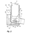
容器ユニット60は、第一副ハウジング30の吸入領域12内に挿入される。この容器ユニットは、媒体容器62、及び出口オリフィス64aを含む出口連結器64を持つ。媒体を媒体容器62から排出する目的のために、妨害する力に対して出口連結器は媒体容器62に対して変位されることができる。容器ユニットが第一副ハウジング30中に既に挿入されている図1に示された状態では、出口連結器64は検出壁部34の収容凹所34b内に位置されている。出口連結器64及び収容凹所34bは、それらが不確動クランプ連結を形成するような方法で適合されることができる。媒体容器62の上端は空気取入れ口14を通して第一副ハウジング30から突出し、その突出部は吸入器10の起動のためを意図されている。
The
第二副ハウジング40は吸入器10の全ての電子要素を含み、これらの要素は図中に単に概略的に表わされている。電子要素はメインボード70を含み、その上に集積回路72、電池74の形態のエネルギー貯蔵装置、及びLCDディスプレイ76が設けられている。LCDディスプレイ76は、第二副ハウジング40の壁内の開口42を通して読まれることができるような方法で位置決めされている。第二副ハウジング40は検出壁部34の領域内に開口44を含む。プッシュボタン78はこの開口44の下のメインボード70上に配置されている。
The second
前述の電子要素70,72,74,76はプッシュボタン78の作動を検出しかつ数えるように構成されており、得られる作動数はディスプレイ76上に示される。従って、電子要素はともに、起こった排出操作を数える役目をする。
The aforementioned
吸入器の操作モードは以下の通りである。意図されるように吸入器を操作する目的のために、マウスピース16が使用者の唇により囲まれ、次いで使用者が空気を吸い込む。同時に、媒体容器62は第一副ハウジング30の主要部32に対して手動で矢印4の方向に押し下げられる。図2に示すように、これは、第一に媒体容器62に対して押される出口連結器64をもたらす。さらに、連結領域36の同時弾性偏向はまた、第一副ハウジング30に付属する検出壁部34を押し下げさせる。そうするとき、検出壁部34は、開口44を通して第二副ハウジング40に入り、プッシュボタン78と接触する。媒体容器62の連続した変位は、ほぼ同時にプッシュボタン78により集積回路72に承認信号を送らせかつ媒体を排出する操作が始まり、その行程中に媒体は媒体容器62から矢印6の方向に吸入領域12中に移り、そこでそれは矢印8の方向に使用者により吸い込まれる空気と混合し、この混合物が使用者によりマウスピース16を通して吸引される。
The operating mode of the inhaler is as follows. For the purpose of operating the inhaler as intended, the
上述のように、排出操作は、制御スイッチ78の作動のために集積回路72により検出され、LCDディスプレイ76上に示される。LCDディスプレイ76上に示された投与の数は、容器内にまだ残る投与に関連付けられるか、または既に投与された投与に関連付けられることができる。
As described above, the eject operation is detected by integrated
いったん媒体容器62内の投与の全てが消費されたら、副ハウジング30,40は互いから結合を外されることができ、新しい容器ユニット60を含む新しい第一副ハウジング30が電子要素70,72,74,76,78を含む再使用可能な第二副ハウジング40に結合されることができる。
Once all of the administration in the
本発明の開発(図示せず)では、第二副ハウジング40に付属する開口44はまた、分離された第二副ハウジング40が環境から密封封止されるように膜または検出壁部34aと似た構成の壁部により閉じられることができる。
In the development of the present invention (not shown), the
Claims (9)
− マウスピース(16)を持つハウジング(20)、
− 前記ハウジング(20)の吸入領域(12)内に収容され、かつ媒体容器(62)、及び出口オリフィス(64a)を持つ出口連結器(64)を含む容器ユニット(60)であって、前記出口連結器が、排出操作を起動する目的のために前記媒体容器(62)に対して動かされることができるもの、及び
− 排出操作の検出のための排出センサ(78)、
を含み、
− 前記ハウジング(20)が、主要部(32)、及び前記主要部(32)に対して動かされることができる検出壁部(34)を持ち、この検出壁部(34)が排出操作時に前記主要部(32)に対して変位されるような態様で構成され、前記検出壁部(34)が、前記出口連結器(64)のための収容凹所(34b)を持ち、
− 前記排出センサ(78)が、前記ハウジング(20)の前記主要部(32)に対して検出壁部(34)の変位を検出するのに適合している、
ことを特徴とする吸入器。 An inhaler (10) for oral administration of a pharmaceutical medium,
A housing (20) with a mouthpiece (16),
A container unit (60) housed in the suction area (12) of the housing (20) and comprising a media container (62) and an outlet connector (64) having an outlet orifice (64a), An outlet coupler that can be moved relative to said media container (62) for the purpose of triggering a discharge operation; and-a discharge sensor (78) for detection of the discharge operation;
Including
The housing (20) has a main part (32) and a detection wall part (34) which can be moved relative to the main part (32); Configured to be displaced relative to the main part (32), the detection wall (34) has a receiving recess (34b) for the outlet coupler (64),
The discharge sensor (78) is adapted to detect the displacement of the detection wall (34) relative to the main part (32) of the housing (20);
An inhaler characterized by that.
− 第一副ハウジング(30)が前記吸入領域(12)を取り囲みかつ前記検出壁部(34)を含み、
− 第二副ハウジング(40)が前記排出センサ(78)を含む、
ことを特徴とする請求項1に記載の吸入器。 Said housing (20) has two sub-housings (30, 40) which can be joined together by a coupling device (18);
A first sub-housing (30) surrounds the suction area (12) and includes the detection wall (34);
The second sub-housing (40) includes the discharge sensor (78);
The inhaler according to claim 1.
Applications Claiming Priority (2)
| Application Number | Priority Date | Filing Date | Title |
|---|---|---|---|
| DE102010024912.2 | 2010-06-15 | ||
| DE102010024912A DE102010024912B4 (en) | 2010-06-15 | 2010-06-15 | inhalator |
Publications (3)
| Publication Number | Publication Date |
|---|---|
| JP2012000461A JP2012000461A (en) | 2012-01-05 |
| JP2012000461A5 JP2012000461A5 (en) | 2014-04-24 |
| JP5749090B2 true JP5749090B2 (en) | 2015-07-15 |
Family
ID=44118150
Family Applications (1)
| Application Number | Title | Priority Date | Filing Date |
|---|---|---|---|
| JP2011132173A Active JP5749090B2 (en) | 2010-06-15 | 2011-06-14 | Inhaler |
Country Status (4)
| Country | Link |
|---|---|
| US (1) | US8746238B2 (en) |
| EP (1) | EP2397178B1 (en) |
| JP (1) | JP5749090B2 (en) |
| DE (1) | DE102010024912B4 (en) |
Families Citing this family (12)
| Publication number | Priority date | Publication date | Assignee | Title |
|---|---|---|---|---|
| DE102013214601B3 (en) | 2013-07-25 | 2014-05-22 | Aptar Radolfzell Gmbh | Housing for container unit of inhalation device e.g. metered-dose inhaler, for oral administration of pharmaceutical medium, has membrane reversibly deformed based on pressure in pressure chamber and acting together with pushbutton |
| DE102014206350B3 (en) * | 2014-04-02 | 2015-05-21 | Aptar Radolfzell Gmbh | Pharmaceutical dispenser with a detection device |
| JP6542387B2 (en) * | 2015-05-01 | 2019-07-10 | アボット・ラボラトリーズAbbott Laboratories | Device for removing the liquid content of a container |
| CN108136144B (en) | 2015-07-20 | 2020-10-30 | 珍珠治疗公司 | Aerosol delivery system |
| JP7155010B2 (en) | 2016-03-24 | 2022-10-18 | トゥルーデル メディカル インターナショナル | Respiratory therapy system with electronic indicators |
| CA3201693A1 (en) | 2016-05-19 | 2017-11-23 | Trudell Medical International | Smart valved holding chamber |
| ES2894895T3 (en) | 2016-07-08 | 2022-02-16 | Trudell Medical Int | Intelligent oscillating positive expiratory pressure device |
| CA3043965A1 (en) | 2016-11-18 | 2018-05-24 | Norton (Waterford) Limited | Drug delivery device with electronics |
| CA3036631A1 (en) | 2016-12-09 | 2018-06-14 | Trudell Medical International | Smart nebulizer |
| MX2020007026A (en) | 2018-01-04 | 2020-12-03 | Trudell Medical Int | Smart oscillating positive expiratory pressure device. |
| CA3101434A1 (en) | 2018-06-04 | 2019-12-12 | Trudell Medical International | Smart valved holding chamber |
| CA3152072A1 (en) | 2019-08-27 | 2021-03-04 | Trudell Medical International | Smart oscillating positive expiratory pressure device |
Family Cites Families (20)
| Publication number | Priority date | Publication date | Assignee | Title |
|---|---|---|---|---|
| GB1413285A (en) * | 1971-11-25 | 1975-11-12 | Bespak Industries Ltd | Aerosol devices |
| US4509515A (en) * | 1982-02-23 | 1985-04-09 | Fisons Plc | Inhalation device |
| GB8924823D0 (en) | 1989-11-03 | 1989-12-20 | Smith Kline French Lab | Dosage inhalers |
| GB9020555D0 (en) * | 1990-09-20 | 1990-10-31 | Bespak Plc | Dispensing apparatus |
| WO1992017231A1 (en) * | 1991-03-28 | 1992-10-15 | Innomed, Inc. | Microelectronic inhaler having a counter and timer |
| JPH06275764A (en) | 1993-03-19 | 1994-09-30 | Fujitsu Miyagi Electron:Kk | Lead frame and manufacture of semiconductor device using same |
| US6390088B1 (en) | 1993-12-13 | 2002-05-21 | Boehringer Ingelheim Kg | Aerosol inhaler |
| DE4422710C1 (en) | 1994-06-29 | 1995-09-14 | Boehringer Ingelheim Kg | Inhaler with storage container for aerosol |
| US5544647A (en) * | 1994-11-29 | 1996-08-13 | Iep Group, Inc. | Metered dose inhalator |
| US6029659A (en) * | 1995-04-17 | 2000-02-29 | Solar Shield Corporation | Inhalation device with counter |
| US5758638A (en) * | 1995-07-24 | 1998-06-02 | Kreamer; Jeffry W. | Indicator for a medicament inhaler |
| US5724986A (en) * | 1995-11-06 | 1998-03-10 | Jones Medical Instrument Co. | Casing and spirometer for metered dose inhaler |
| US5676129A (en) * | 1996-03-14 | 1997-10-14 | Oneida Research Services, Inc. | Dosage counter for metered dose inhaler (MDI) systems using a miniature pressure sensor |
| US5954047A (en) * | 1997-10-17 | 1999-09-21 | Systemic Pulmonary Development, Ltd. | Methods and apparatus for delivering aerosolized medication |
| GB2344535B (en) * | 1998-12-11 | 2000-10-18 | Bespak Plc | Inhalation apparatus |
| US20050028815A1 (en) | 2003-07-23 | 2005-02-10 | Deaton Daniel M. | Apparatus for electronic dosage counter |
| GB2398065A (en) * | 2003-10-16 | 2004-08-11 | Bespak Plc | Dispensing apparatus |
| EP1991295B1 (en) * | 2006-03-03 | 2016-02-10 | 3M Innovative Properties Company | Apparatus for metered dosed dispensing |
| DE102006032293A1 (en) | 2006-07-11 | 2008-01-24 | Friedrich Sanner Gmbh & Co. Kg | Device for the metered delivery of sprayable substances |
| GB2470188B (en) * | 2009-05-11 | 2011-06-22 | Consort Medical Plc | Improvements in or relating to dispensing apparatus and dose counters |
-
2010
- 2010-06-15 DE DE102010024912A patent/DE102010024912B4/en not_active Expired - Fee Related
-
2011
- 2011-06-01 EP EP11168488.2A patent/EP2397178B1/en active Active
- 2011-06-10 US US13/134,611 patent/US8746238B2/en active Active
- 2011-06-14 JP JP2011132173A patent/JP5749090B2/en active Active
Also Published As
| Publication number | Publication date |
|---|---|
| US20110303221A1 (en) | 2011-12-15 |
| JP2012000461A (en) | 2012-01-05 |
| DE102010024912A1 (en) | 2011-12-15 |
| EP2397178B1 (en) | 2013-11-27 |
| EP2397178A1 (en) | 2011-12-21 |
| DE102010024912B4 (en) | 2013-02-28 |
| US8746238B2 (en) | 2014-06-10 |
Similar Documents
| Publication | Publication Date | Title |
|---|---|---|
| JP5749090B2 (en) | Inhaler | |
| CA2532868C (en) | Apparatus for electronic dosage counter | |
| KR102018927B1 (en) | Inhaler | |
| EP3393561B1 (en) | Auto-reset dose release firing system and medicinal inhaler comprising same | |
| CA2557002C (en) | Atomizer provided with a monitoring device for counting actuations of the atomizer | |
| JP6921856B2 (en) | Intake synchronous fluid discharge device | |
| US20220096761A1 (en) | Device for inhalation-synchronized dispensing of a fluid product, and method for assembling said device | |
| JP6014147B2 (en) | Inhaler | |
| KR20080005992A (en) | Breath actuated inhaler | |
| EP1893261A1 (en) | Dose counter for metered dose inhalers | |
| CN113382761B (en) | Device for dispensing a fluid preparation in synchronism with inhalation | |
| JP7463384B2 (en) | Intake-synchronized fluid product discharge device | |
| US10821241B2 (en) | Housing for an inhalation device and inhalation device for orally administering a pharmaceutical medium | |
| JP5264230B2 (en) | Drug discharge device and control method thereof | |
| JP2021500115A (en) | Intake synchronous fluid discharge device |
Legal Events
| Date | Code | Title | Description |
|---|---|---|---|
| A521 | Request for written amendment filed |
Free format text: JAPANESE INTERMEDIATE CODE: A523 Effective date: 20140310 |
|
| A621 | Written request for application examination |
Free format text: JAPANESE INTERMEDIATE CODE: A621 Effective date: 20140310 |
|
| A977 | Report on retrieval |
Free format text: JAPANESE INTERMEDIATE CODE: A971007 Effective date: 20141208 |
|
| A131 | Notification of reasons for refusal |
Free format text: JAPANESE INTERMEDIATE CODE: A131 Effective date: 20141212 |
|
| A521 | Request for written amendment filed |
Free format text: JAPANESE INTERMEDIATE CODE: A523 Effective date: 20150219 |
|
| TRDD | Decision of grant or rejection written | ||
| A01 | Written decision to grant a patent or to grant a registration (utility model) |
Free format text: JAPANESE INTERMEDIATE CODE: A01 Effective date: 20150501 |
|
| A61 | First payment of annual fees (during grant procedure) |
Free format text: JAPANESE INTERMEDIATE CODE: A61 Effective date: 20150513 |
|
| R150 | Certificate of patent or registration of utility model |
Ref document number: 5749090 Country of ref document: JP Free format text: JAPANESE INTERMEDIATE CODE: R150 |
|
| R250 | Receipt of annual fees |
Free format text: JAPANESE INTERMEDIATE CODE: R250 |
|
| R250 | Receipt of annual fees |
Free format text: JAPANESE INTERMEDIATE CODE: R250 |
|
| R250 | Receipt of annual fees |
Free format text: JAPANESE INTERMEDIATE CODE: R250 |
|
| R250 | Receipt of annual fees |
Free format text: JAPANESE INTERMEDIATE CODE: R250 |
|
| R250 | Receipt of annual fees |
Free format text: JAPANESE INTERMEDIATE CODE: R250 |
|
| R250 | Receipt of annual fees |
Free format text: JAPANESE INTERMEDIATE CODE: R250 |
|
| R250 | Receipt of annual fees |
Free format text: JAPANESE INTERMEDIATE CODE: R250 |