JP5744094B2 - Control method of fuel cell system - Google Patents
Control method of fuel cell system Download PDFInfo
- Publication number
- JP5744094B2 JP5744094B2 JP2013067543A JP2013067543A JP5744094B2 JP 5744094 B2 JP5744094 B2 JP 5744094B2 JP 2013067543 A JP2013067543 A JP 2013067543A JP 2013067543 A JP2013067543 A JP 2013067543A JP 5744094 B2 JP5744094 B2 JP 5744094B2
- Authority
- JP
- Japan
- Prior art keywords
- fuel cell
- stop
- fuel gas
- fuel
- pressure
- Prior art date
- Legal status (The legal status is an assumption and is not a legal conclusion. Google has not performed a legal analysis and makes no representation as to the accuracy of the status listed.)
- Expired - Fee Related
Links
Images


Classifications
-
- B—PERFORMING OPERATIONS; TRANSPORTING
- B60—VEHICLES IN GENERAL
- B60L—PROPULSION OF ELECTRICALLY-PROPELLED VEHICLES; SUPPLYING ELECTRIC POWER FOR AUXILIARY EQUIPMENT OF ELECTRICALLY-PROPELLED VEHICLES; ELECTRODYNAMIC BRAKE SYSTEMS FOR VEHICLES IN GENERAL; MAGNETIC SUSPENSION OR LEVITATION FOR VEHICLES; MONITORING OPERATING VARIABLES OF ELECTRICALLY-PROPELLED VEHICLES; ELECTRIC SAFETY DEVICES FOR ELECTRICALLY-PROPELLED VEHICLES
- B60L3/00—Electric devices on electrically-propelled vehicles for safety purposes; Monitoring operating variables, e.g. speed, deceleration or energy consumption
- B60L3/0023—Detecting, eliminating, remedying or compensating for drive train abnormalities, e.g. failures within the drive train
- B60L3/0053—Detecting, eliminating, remedying or compensating for drive train abnormalities, e.g. failures within the drive train relating to fuel cells
-
- B—PERFORMING OPERATIONS; TRANSPORTING
- B60—VEHICLES IN GENERAL
- B60L—PROPULSION OF ELECTRICALLY-PROPELLED VEHICLES; SUPPLYING ELECTRIC POWER FOR AUXILIARY EQUIPMENT OF ELECTRICALLY-PROPELLED VEHICLES; ELECTRODYNAMIC BRAKE SYSTEMS FOR VEHICLES IN GENERAL; MAGNETIC SUSPENSION OR LEVITATION FOR VEHICLES; MONITORING OPERATING VARIABLES OF ELECTRICALLY-PROPELLED VEHICLES; ELECTRIC SAFETY DEVICES FOR ELECTRICALLY-PROPELLED VEHICLES
- B60L1/00—Supplying electric power to auxiliary equipment of vehicles
- B60L1/003—Supplying electric power to auxiliary equipment of vehicles to auxiliary motors, e.g. for pumps, compressors
-
- B—PERFORMING OPERATIONS; TRANSPORTING
- B60—VEHICLES IN GENERAL
- B60L—PROPULSION OF ELECTRICALLY-PROPELLED VEHICLES; SUPPLYING ELECTRIC POWER FOR AUXILIARY EQUIPMENT OF ELECTRICALLY-PROPELLED VEHICLES; ELECTRODYNAMIC BRAKE SYSTEMS FOR VEHICLES IN GENERAL; MAGNETIC SUSPENSION OR LEVITATION FOR VEHICLES; MONITORING OPERATING VARIABLES OF ELECTRICALLY-PROPELLED VEHICLES; ELECTRIC SAFETY DEVICES FOR ELECTRICALLY-PROPELLED VEHICLES
- B60L3/00—Electric devices on electrically-propelled vehicles for safety purposes; Monitoring operating variables, e.g. speed, deceleration or energy consumption
- B60L3/04—Cutting off the power supply under fault conditions
-
- B—PERFORMING OPERATIONS; TRANSPORTING
- B60—VEHICLES IN GENERAL
- B60L—PROPULSION OF ELECTRICALLY-PROPELLED VEHICLES; SUPPLYING ELECTRIC POWER FOR AUXILIARY EQUIPMENT OF ELECTRICALLY-PROPELLED VEHICLES; ELECTRODYNAMIC BRAKE SYSTEMS FOR VEHICLES IN GENERAL; MAGNETIC SUSPENSION OR LEVITATION FOR VEHICLES; MONITORING OPERATING VARIABLES OF ELECTRICALLY-PROPELLED VEHICLES; ELECTRIC SAFETY DEVICES FOR ELECTRICALLY-PROPELLED VEHICLES
- B60L50/00—Electric propulsion with power supplied within the vehicle
- B60L50/50—Electric propulsion with power supplied within the vehicle using propulsion power supplied by batteries or fuel cells
- B60L50/52—Electric propulsion with power supplied within the vehicle using propulsion power supplied by batteries or fuel cells characterised by DC-motors
-
- B—PERFORMING OPERATIONS; TRANSPORTING
- B60—VEHICLES IN GENERAL
- B60L—PROPULSION OF ELECTRICALLY-PROPELLED VEHICLES; SUPPLYING ELECTRIC POWER FOR AUXILIARY EQUIPMENT OF ELECTRICALLY-PROPELLED VEHICLES; ELECTRODYNAMIC BRAKE SYSTEMS FOR VEHICLES IN GENERAL; MAGNETIC SUSPENSION OR LEVITATION FOR VEHICLES; MONITORING OPERATING VARIABLES OF ELECTRICALLY-PROPELLED VEHICLES; ELECTRIC SAFETY DEVICES FOR ELECTRICALLY-PROPELLED VEHICLES
- B60L50/00—Electric propulsion with power supplied within the vehicle
- B60L50/50—Electric propulsion with power supplied within the vehicle using propulsion power supplied by batteries or fuel cells
- B60L50/70—Electric propulsion with power supplied within the vehicle using propulsion power supplied by batteries or fuel cells using power supplied by fuel cells
- B60L50/72—Constructional details of fuel cells specially adapted for electric vehicles
-
- B—PERFORMING OPERATIONS; TRANSPORTING
- B60—VEHICLES IN GENERAL
- B60L—PROPULSION OF ELECTRICALLY-PROPELLED VEHICLES; SUPPLYING ELECTRIC POWER FOR AUXILIARY EQUIPMENT OF ELECTRICALLY-PROPELLED VEHICLES; ELECTRODYNAMIC BRAKE SYSTEMS FOR VEHICLES IN GENERAL; MAGNETIC SUSPENSION OR LEVITATION FOR VEHICLES; MONITORING OPERATING VARIABLES OF ELECTRICALLY-PROPELLED VEHICLES; ELECTRIC SAFETY DEVICES FOR ELECTRICALLY-PROPELLED VEHICLES
- B60L58/00—Methods or circuit arrangements for monitoring or controlling batteries or fuel cells, specially adapted for electric vehicles
- B60L58/30—Methods or circuit arrangements for monitoring or controlling batteries or fuel cells, specially adapted for electric vehicles for monitoring or controlling fuel cells
- B60L58/32—Methods or circuit arrangements for monitoring or controlling batteries or fuel cells, specially adapted for electric vehicles for monitoring or controlling fuel cells for controlling the temperature of fuel cells, e.g. by controlling the electric load
- B60L58/33—Methods or circuit arrangements for monitoring or controlling batteries or fuel cells, specially adapted for electric vehicles for monitoring or controlling fuel cells for controlling the temperature of fuel cells, e.g. by controlling the electric load by cooling
-
- B—PERFORMING OPERATIONS; TRANSPORTING
- B60—VEHICLES IN GENERAL
- B60L—PROPULSION OF ELECTRICALLY-PROPELLED VEHICLES; SUPPLYING ELECTRIC POWER FOR AUXILIARY EQUIPMENT OF ELECTRICALLY-PROPELLED VEHICLES; ELECTRODYNAMIC BRAKE SYSTEMS FOR VEHICLES IN GENERAL; MAGNETIC SUSPENSION OR LEVITATION FOR VEHICLES; MONITORING OPERATING VARIABLES OF ELECTRICALLY-PROPELLED VEHICLES; ELECTRIC SAFETY DEVICES FOR ELECTRICALLY-PROPELLED VEHICLES
- B60L58/00—Methods or circuit arrangements for monitoring or controlling batteries or fuel cells, specially adapted for electric vehicles
- B60L58/40—Methods or circuit arrangements for monitoring or controlling batteries or fuel cells, specially adapted for electric vehicles for controlling a combination of batteries and fuel cells
-
- B—PERFORMING OPERATIONS; TRANSPORTING
- B60—VEHICLES IN GENERAL
- B60L—PROPULSION OF ELECTRICALLY-PROPELLED VEHICLES; SUPPLYING ELECTRIC POWER FOR AUXILIARY EQUIPMENT OF ELECTRICALLY-PROPELLED VEHICLES; ELECTRODYNAMIC BRAKE SYSTEMS FOR VEHICLES IN GENERAL; MAGNETIC SUSPENSION OR LEVITATION FOR VEHICLES; MONITORING OPERATING VARIABLES OF ELECTRICALLY-PROPELLED VEHICLES; ELECTRIC SAFETY DEVICES FOR ELECTRICALLY-PROPELLED VEHICLES
- B60L7/00—Electrodynamic brake systems for vehicles in general
- B60L7/10—Dynamic electric regenerative braking
- B60L7/12—Dynamic electric regenerative braking for vehicles propelled by DC motors
-
- H—ELECTRICITY
- H01—ELECTRIC ELEMENTS
- H01M—PROCESSES OR MEANS, e.g. BATTERIES, FOR THE DIRECT CONVERSION OF CHEMICAL ENERGY INTO ELECTRICAL ENERGY
- H01M8/00—Fuel cells; Manufacture thereof
- H01M8/04—Auxiliary arrangements, e.g. for control of pressure or for circulation of fluids
- H01M8/04082—Arrangements for control of reactant parameters, e.g. pressure or concentration
- H01M8/04201—Reactant storage and supply, e.g. means for feeding, pipes
-
- H—ELECTRICITY
- H01—ELECTRIC ELEMENTS
- H01M—PROCESSES OR MEANS, e.g. BATTERIES, FOR THE DIRECT CONVERSION OF CHEMICAL ENERGY INTO ELECTRICAL ENERGY
- H01M8/00—Fuel cells; Manufacture thereof
- H01M8/04—Auxiliary arrangements, e.g. for control of pressure or for circulation of fluids
- H01M8/04223—Auxiliary arrangements, e.g. for control of pressure or for circulation of fluids during start-up or shut-down; Depolarisation or activation, e.g. purging; Means for short-circuiting defective fuel cells
- H01M8/04228—Auxiliary arrangements, e.g. for control of pressure or for circulation of fluids during start-up or shut-down; Depolarisation or activation, e.g. purging; Means for short-circuiting defective fuel cells during shut-down
-
- H—ELECTRICITY
- H01—ELECTRIC ELEMENTS
- H01M—PROCESSES OR MEANS, e.g. BATTERIES, FOR THE DIRECT CONVERSION OF CHEMICAL ENERGY INTO ELECTRICAL ENERGY
- H01M8/00—Fuel cells; Manufacture thereof
- H01M8/04—Auxiliary arrangements, e.g. for control of pressure or for circulation of fluids
- H01M8/04298—Processes for controlling fuel cells or fuel cell systems
- H01M8/043—Processes for controlling fuel cells or fuel cell systems applied during specific periods
- H01M8/04303—Processes for controlling fuel cells or fuel cell systems applied during specific periods applied during shut-down
-
- B—PERFORMING OPERATIONS; TRANSPORTING
- B60—VEHICLES IN GENERAL
- B60L—PROPULSION OF ELECTRICALLY-PROPELLED VEHICLES; SUPPLYING ELECTRIC POWER FOR AUXILIARY EQUIPMENT OF ELECTRICALLY-PROPELLED VEHICLES; ELECTRODYNAMIC BRAKE SYSTEMS FOR VEHICLES IN GENERAL; MAGNETIC SUSPENSION OR LEVITATION FOR VEHICLES; MONITORING OPERATING VARIABLES OF ELECTRICALLY-PROPELLED VEHICLES; ELECTRIC SAFETY DEVICES FOR ELECTRICALLY-PROPELLED VEHICLES
- B60L2210/00—Converter types
- B60L2210/10—DC to DC converters
-
- B—PERFORMING OPERATIONS; TRANSPORTING
- B60—VEHICLES IN GENERAL
- B60L—PROPULSION OF ELECTRICALLY-PROPELLED VEHICLES; SUPPLYING ELECTRIC POWER FOR AUXILIARY EQUIPMENT OF ELECTRICALLY-PROPELLED VEHICLES; ELECTRODYNAMIC BRAKE SYSTEMS FOR VEHICLES IN GENERAL; MAGNETIC SUSPENSION OR LEVITATION FOR VEHICLES; MONITORING OPERATING VARIABLES OF ELECTRICALLY-PROPELLED VEHICLES; ELECTRIC SAFETY DEVICES FOR ELECTRICALLY-PROPELLED VEHICLES
- B60L2240/00—Control parameters of input or output; Target parameters
- B60L2240/10—Vehicle control parameters
- B60L2240/36—Temperature of vehicle components or parts
-
- B—PERFORMING OPERATIONS; TRANSPORTING
- B60—VEHICLES IN GENERAL
- B60L—PROPULSION OF ELECTRICALLY-PROPELLED VEHICLES; SUPPLYING ELECTRIC POWER FOR AUXILIARY EQUIPMENT OF ELECTRICALLY-PROPELLED VEHICLES; ELECTRODYNAMIC BRAKE SYSTEMS FOR VEHICLES IN GENERAL; MAGNETIC SUSPENSION OR LEVITATION FOR VEHICLES; MONITORING OPERATING VARIABLES OF ELECTRICALLY-PROPELLED VEHICLES; ELECTRIC SAFETY DEVICES FOR ELECTRICALLY-PROPELLED VEHICLES
- B60L2240/00—Control parameters of input or output; Target parameters
- B60L2240/80—Time limits
-
- B—PERFORMING OPERATIONS; TRANSPORTING
- B60—VEHICLES IN GENERAL
- B60L—PROPULSION OF ELECTRICALLY-PROPELLED VEHICLES; SUPPLYING ELECTRIC POWER FOR AUXILIARY EQUIPMENT OF ELECTRICALLY-PROPELLED VEHICLES; ELECTRODYNAMIC BRAKE SYSTEMS FOR VEHICLES IN GENERAL; MAGNETIC SUSPENSION OR LEVITATION FOR VEHICLES; MONITORING OPERATING VARIABLES OF ELECTRICALLY-PROPELLED VEHICLES; ELECTRIC SAFETY DEVICES FOR ELECTRICALLY-PROPELLED VEHICLES
- B60L2250/00—Driver interactions
- B60L2250/16—Driver interactions by display
-
- Y—GENERAL TAGGING OF NEW TECHNOLOGICAL DEVELOPMENTS; GENERAL TAGGING OF CROSS-SECTIONAL TECHNOLOGIES SPANNING OVER SEVERAL SECTIONS OF THE IPC; TECHNICAL SUBJECTS COVERED BY FORMER USPC CROSS-REFERENCE ART COLLECTIONS [XRACs] AND DIGESTS
- Y02—TECHNOLOGIES OR APPLICATIONS FOR MITIGATION OR ADAPTATION AGAINST CLIMATE CHANGE
- Y02E—REDUCTION OF GREENHOUSE GAS [GHG] EMISSIONS, RELATED TO ENERGY GENERATION, TRANSMISSION OR DISTRIBUTION
- Y02E60/00—Enabling technologies; Technologies with a potential or indirect contribution to GHG emissions mitigation
- Y02E60/30—Hydrogen technology
- Y02E60/50—Fuel cells
-
- Y—GENERAL TAGGING OF NEW TECHNOLOGICAL DEVELOPMENTS; GENERAL TAGGING OF CROSS-SECTIONAL TECHNOLOGIES SPANNING OVER SEVERAL SECTIONS OF THE IPC; TECHNICAL SUBJECTS COVERED BY FORMER USPC CROSS-REFERENCE ART COLLECTIONS [XRACs] AND DIGESTS
- Y02—TECHNOLOGIES OR APPLICATIONS FOR MITIGATION OR ADAPTATION AGAINST CLIMATE CHANGE
- Y02T—CLIMATE CHANGE MITIGATION TECHNOLOGIES RELATED TO TRANSPORTATION
- Y02T10/00—Road transport of goods or passengers
- Y02T10/60—Other road transportation technologies with climate change mitigation effect
- Y02T10/70—Energy storage systems for electromobility, e.g. batteries
-
- Y—GENERAL TAGGING OF NEW TECHNOLOGICAL DEVELOPMENTS; GENERAL TAGGING OF CROSS-SECTIONAL TECHNOLOGIES SPANNING OVER SEVERAL SECTIONS OF THE IPC; TECHNICAL SUBJECTS COVERED BY FORMER USPC CROSS-REFERENCE ART COLLECTIONS [XRACs] AND DIGESTS
- Y02—TECHNOLOGIES OR APPLICATIONS FOR MITIGATION OR ADAPTATION AGAINST CLIMATE CHANGE
- Y02T—CLIMATE CHANGE MITIGATION TECHNOLOGIES RELATED TO TRANSPORTATION
- Y02T10/00—Road transport of goods or passengers
- Y02T10/60—Other road transportation technologies with climate change mitigation effect
- Y02T10/72—Electric energy management in electromobility
-
- Y—GENERAL TAGGING OF NEW TECHNOLOGICAL DEVELOPMENTS; GENERAL TAGGING OF CROSS-SECTIONAL TECHNOLOGIES SPANNING OVER SEVERAL SECTIONS OF THE IPC; TECHNICAL SUBJECTS COVERED BY FORMER USPC CROSS-REFERENCE ART COLLECTIONS [XRACs] AND DIGESTS
- Y02—TECHNOLOGIES OR APPLICATIONS FOR MITIGATION OR ADAPTATION AGAINST CLIMATE CHANGE
- Y02T—CLIMATE CHANGE MITIGATION TECHNOLOGIES RELATED TO TRANSPORTATION
- Y02T90/00—Enabling technologies or technologies with a potential or indirect contribution to GHG emissions mitigation
- Y02T90/10—Technologies relating to charging of electric vehicles
- Y02T90/16—Information or communication technologies improving the operation of electric vehicles
-
- Y—GENERAL TAGGING OF NEW TECHNOLOGICAL DEVELOPMENTS; GENERAL TAGGING OF CROSS-SECTIONAL TECHNOLOGIES SPANNING OVER SEVERAL SECTIONS OF THE IPC; TECHNICAL SUBJECTS COVERED BY FORMER USPC CROSS-REFERENCE ART COLLECTIONS [XRACs] AND DIGESTS
- Y02—TECHNOLOGIES OR APPLICATIONS FOR MITIGATION OR ADAPTATION AGAINST CLIMATE CHANGE
- Y02T—CLIMATE CHANGE MITIGATION TECHNOLOGIES RELATED TO TRANSPORTATION
- Y02T90/00—Enabling technologies or technologies with a potential or indirect contribution to GHG emissions mitigation
- Y02T90/40—Application of hydrogen technology to transportation, e.g. using fuel cells
Landscapes
- Engineering & Computer Science (AREA)
- Sustainable Energy (AREA)
- Life Sciences & Earth Sciences (AREA)
- Sustainable Development (AREA)
- Power Engineering (AREA)
- Transportation (AREA)
- Mechanical Engineering (AREA)
- Chemical & Material Sciences (AREA)
- Chemical Kinetics & Catalysis (AREA)
- Electrochemistry (AREA)
- General Chemical & Material Sciences (AREA)
- Manufacturing & Machinery (AREA)
- Fuel Cell (AREA)
- Filling Or Discharging Of Gas Storage Vessels (AREA)
Description
本発明は、燃料電池システムの制御方法に関する。より詳しくは、燃料電池システムへの停止指令後に、燃料電池による発電及びディスチャージを継続する燃料電池システムの制御方法に関する。 The present invention relates to a control method for a fuel cell system. More specifically, the present invention relates to a control method for a fuel cell system that continues power generation and discharge by the fuel cell after a stop command to the fuel cell system.
燃料電池車両は、その電源システムとして燃料電池システムを備える。燃料電池は、燃料ガスである水素ガスと酸化剤ガスである空気とが供給されると発電する。燃料電池に水素ガスを供給するため、燃料電池のアノード流路には水素ガス供給管を介して水素タンクが接続されている。また、燃料電池に空気を供給するため、燃料電池のカソード流路には空気供給管を介してコンプレッサが接続されている。燃料電池システムは、起動されると水素ガス及び空気の供給を開始し、燃料電池による発電を開始する。 The fuel cell vehicle includes a fuel cell system as its power supply system. The fuel cell generates power when supplied with hydrogen gas, which is fuel gas, and air, which is oxidant gas. In order to supply hydrogen gas to the fuel cell, a hydrogen tank is connected to the anode flow path of the fuel cell via a hydrogen gas supply pipe. In order to supply air to the fuel cell, a compressor is connected to the cathode channel of the fuel cell via an air supply pipe. When the fuel cell system is activated, it starts supplying hydrogen gas and air, and starts power generation by the fuel cell.
システムの停止中に、カソード流路内に酸素が残ったままであると、次回のシステム起動時にアノード系に水素を供給したときに燃料電池のカソード側が高電位状態になってしまい、燃料電池の固体高分子電解質膜が劣化するおそれがある。このため、燃料電池システムでは、システムの停止時にカソード流路内に残留する酸素を用いて燃料電池による発電及びディスチャージを継続し、燃料電池を不活性状態にした上でシステムを完全に停止させている(特許文献1参照)。また、このディスチャージ処理では、カソード側からアノード側への酸素透過をさらに抑制するため、カソード側では残留酸素を消費させ、アノード側には水素タンクから余分に水素ガスを供給し、アノード流路内の圧力を高くしておく方が好ましいことも知られている。 If oxygen remains in the cathode flow path while the system is shut down, the cathode side of the fuel cell will be in a high potential state when hydrogen is supplied to the anode system at the next system start-up. The polymer electrolyte membrane may be deteriorated. Therefore, in the fuel cell system, when the system is stopped, oxygen remaining in the cathode flow path is used to continue power generation and discharge by the fuel cell, and after the fuel cell is in an inactive state, the system is completely stopped. (See Patent Document 1). In this discharge process, in order to further suppress oxygen permeation from the cathode side to the anode side, residual oxygen is consumed on the cathode side, and extra hydrogen gas is supplied from the hydrogen tank to the anode side, It is also known that it is preferable to keep the pressure at a high value.
一方、近年では水素タンク内に水素ガスを充填するための技術についても盛んに研究が進められている。例えば特許文献2の技術では、水素ステーションの水素充填装置と燃料電池車両とを接続し、その水素タンク内に水素ガスを充填する際、車両側からはタンクの温度や圧力等に関するデータ信号をステーション側に送信し、ステーション側では受信したデータ信号に基づいて最適な態様で水素ガスを充填する。このように車両側とステーション側とで通信を行いながら水素ガスを充填する技術を、以下では通信充填という。
On the other hand, in recent years, research on a technique for filling hydrogen gas into a hydrogen tank has been actively conducted. For example, in the technique of
上記ディスチャージ処理は、利用者によるシステム停止操作を契機として、システム停止操作後も継続して行われる処理である。そして水素ガスの充填は、システム停止操作後に、利用者の意思に基づいて行われる処理である。したがって、システム停止操作後にディスチャージ処理を行っている間に、水素ガスを充填する操作が行われることがあり得るが、このような場合にどちらの処理を優先して行うか、又はどのような態様で両方の処理を並行して行うか等については十分に検討されていない。例えば、通信充填と並行してディスチャージ処理を行うとなると、水素タンクの状態が変動してしまい、車両側からは正確な水素タンクの状態に関するデータを送信できず、充填に時間がかかったり満充填できなくなったりするおそれがある。 The discharge process is a process that is continuously performed after the system stop operation triggered by the system stop operation by the user. The filling of hydrogen gas is a process performed based on the user's intention after the system stop operation. Therefore, an operation of filling hydrogen gas may be performed during the discharge process after the system stop operation. In such a case, which process is given priority or what kind of mode is performed. Whether or not both processes are performed in parallel has not been fully studied. For example, if discharge processing is performed in parallel with communication filling, the state of the hydrogen tank will fluctuate, and the vehicle side will not be able to transmit accurate data on the state of the hydrogen tank, and filling will take time or will be full. There is a risk of being unable to do so.
本発明は、システム停止指令後に燃料電池による発電及びディスチャージを継続して行う燃料電池システムの制御方法であって、停止後のディスチャージに係る処理と通信充填に係る処理とを適切な態様で行うことを目的とする。 The present invention is a control method of a fuel cell system that continuously performs power generation and discharge by a fuel cell after a system stop command, and performs processing related to discharge after stop and processing related to communication filling in an appropriate manner. With the goal.
(1)燃料電池システム(例えば、後述の燃料電池システム1)は、燃料ガス及び酸化剤ガスが供給されると発電する燃料電池(例えば、後述のスタック2)と、燃料ガスを貯蔵する貯蔵容器(例えば、後述のタンク本体311)と、前記貯蔵容器と前記燃料電池とを接続する燃料ガス供給路(例えば、後述の水素供給管32)と、前記燃料ガス供給路に設けられた開閉弁(例えば、後述の主止弁312)と、前記貯蔵容器の状態を示すデータ信号を外部へ送信する送信手段(例えば、後述の赤外線送信器66)と、を備える。この燃料電池システムの制御方法は、前記燃料電池システムへの停止指令後に、前記開閉弁を開き、前記燃料電池へ燃料ガスを供給し、前記燃料電池による発電及びディスチャージを継続する停止後ディスチャージ工程(例えば、後述の図3に示すEGR停止処理)と、前記貯蔵容器への燃料ガスの充填指令が出力されたことに応じて、前記貯蔵容器の状態を示すデータ信号を外部の燃料供給源(例えば、後述の水素ステーション9)に送信しながら、当該外部の燃料供給源から供給された燃料ガスを前記貯蔵容器に充填する充填工程(例えば、後述の通信充填)と、前記停止後ディスチャージ工程を行っている間に前記充填指令が出力された場合には、前記開閉弁を閉じた後に、前記充填工程を開始する切替工程(例えば、後述の図4、6、8に示す割込制御)と、を含む。
(1) A fuel cell system (for example, a
(2)この場合、前記制御方法は、前記停止後ディスチャージ工程とは別の工程であって、前記燃料電池への燃料ガスの供給を伴わないシステム停止処理(例えば、後述の希釈処理、冷却処理等)を前記燃料電池システムへの停止指令後に行う停止処理工程さらに含み、前記切替工程では、前記停止処理工程と前記停止後ディスチャージ工程とを並行して行っている間に前記充填指令が出力された場合には、前記開閉弁を閉じ、前記充填工程と前記停止処理工程とを並行して行うことが好ましい。 (2) In this case, the control method is a process different from the post-stop discharge process, and is a system stop process (for example, a dilution process and a cooling process described later) that does not involve the supply of fuel gas to the fuel cell. Etc.) after the stop command to the fuel cell system is further included. In the switching step, the filling command is output while the stop processing step and the post-stop discharge step are performed in parallel. In this case, it is preferable that the on-off valve is closed and the filling step and the stop processing step are performed in parallel.
(3)この場合、前記燃料電池システムは、前記燃料電池の燃料ガス排出部と前記燃料ガス供給路とを接続して構成される燃料ガス循環流路(例えば、後述の水素循環流路)と、前記燃料電池の酸化剤ガス導入部と酸化剤ガス排出部とを接続して構成される酸化剤循環流路(例えば、後述の酸素循環流路)と、前記燃料ガス循環流路内の圧力を検出する燃料ガス圧検出手段(例えば、後述のアノード圧センサ27)と、をさらに備え、前記停止後ディスチャージ工程では、前記燃料電池システムの停止指令後に、前記開閉弁を開いた状態で前記燃料ガス循環流路内の燃料ガスを循環させかつ前記酸化剤循環流路内の酸化剤ガスを循環させることによって、前記酸化剤循環流路内の酸素濃度が所定濃度に低下するまで前記燃料電池による発電及びディスチャージを行い、前記切替工程では、前記開閉弁を閉じた後、前記燃料ガス圧検出手段によって検出された圧力が所定の下限圧力(例えば、後述の図7の下限圧)を下回るまでは前記停止後ディスチャージ工程と前記充填工程とを並行して実行し、前記検出された圧力が前記下限圧力を下回った後は前記充填工程が完了するまで前記停止後ディスチャージ工程を中断することが好ましい。
(3) In this case, the fuel cell system includes a fuel gas circulation passage (for example, a hydrogen circulation passage described later) configured by connecting a fuel gas discharge portion of the fuel cell and the fuel gas supply passage. An oxidant circulation channel (for example, an oxygen circulation channel described later) configured by connecting an oxidant gas introduction unit and an oxidant gas discharge unit of the fuel cell, and a pressure in the fuel gas circulation channel Fuel gas pressure detection means (for example, an
(4)この場合、前記燃料電池システムは、前記燃料電池の燃料ガス排出部と前記燃料ガス供給路とを接続して構成される燃料ガス循環流路と、前記燃料電池の酸化剤ガス導入部と酸化剤ガス排出部とを接続して構成される酸化剤循環流路と、前記燃料ガス供給路のうち前記開閉弁より下流側に設けられ、前記貯蔵容器から供給された燃料ガスを前記燃料ガス循環流路内に供給する燃料ガスインジェクタ(例えば、後述のインジェクタ35)と、をさらに備え、前記停止後ディスチャージ工程では、前記燃料電池システムの停止指令後に、前記開閉弁を開いた状態で前記燃料ガスインジェクタによって前記燃料ガス循環流路内の圧力を所定の第1圧力(例えば、後述の図9のディスチャージ時目標圧)に制御しながら前記酸化剤循環流路内の酸化剤ガスを循環させることによって、前記酸化剤循環流路内の酸素濃度が所定濃度に低下するまで前記燃料電池による発電及びディスチャージを行い、前記切替工程では、前記充填指令が出力された場合には、前記燃料ガスインジェクタによって前記燃料ガス循環流路内の圧力を前記第1圧力より高い第2圧力(例えば、後述の図9の閉弁前目標圧)まで昇圧してから前記開閉弁を閉じ、前記停止後ディスチャージ工程と前記充填工程とを並行して行うことが好ましい。
(4) In this case, the fuel cell system includes a fuel gas circulation passage configured by connecting a fuel gas discharge portion of the fuel cell and the fuel gas supply passage, and an oxidant gas introduction portion of the fuel cell. And an oxidant gas discharge section connected to each other, and an oxidant circulation path configured to be connected to the fuel gas supply path downstream of the on-off valve and the fuel gas supplied from the storage container to the fuel A fuel gas injector (for example, an
(1)停止後ディスチャージ工程は燃料電池の劣化を抑制するために利用者の意思とは無関係に行われる処理であり、充填工程は貯蔵容器に燃料ガスを充填するために利用者の意思に基づいて行われる処理である。そしてこれらは何れも燃料電池システムの停止指令後に実行される処理である。本発明では、停止後ディスチャージ工程を行っている間に充填指令が生じた場合には、開閉弁を閉じた後に充填工程を開始する。すなわち、利用者からすれば自身の意思に基づいて行われる充填工程が実行中の停止後ディスチャージ工程に優先して行われるため、利便性を向上できる。また、本発明では、充填工程を開始する前に開閉弁を閉じることにより、充填工程を行っている間に貯蔵容器から燃料ガスが燃料電池へ流出してしまい、貯蔵容器内の圧力や温度が変化するのを防止できる。したがって、充填工程を行っている間、送信手段からは状態が安定しており精度が高いデータ信号を外部の燃料供給源に送信できる。したがって、外部の燃料供給源は、貯蔵容器の状態を正確に把握できるので、短時間で満充填にできる。 (1) The post-stop discharge process is a process performed regardless of the user's intention to suppress the deterioration of the fuel cell, and the filling process is based on the user's intention to fill the storage container with the fuel gas. This process is performed. These are all processes executed after a stop command for the fuel cell system. In the present invention, when a filling command is issued during the discharging process after stopping, the filling process is started after closing the on-off valve. That is, since the filling process performed based on one's intention is performed in preference to the post-stop discharge process being performed, the convenience can be improved. Further, in the present invention, by closing the on-off valve before starting the filling process, the fuel gas flows out from the storage container to the fuel cell during the filling process, and the pressure and temperature in the storage container are reduced. It can be prevented from changing. Therefore, during the filling process, the transmission means can transmit a data signal that is stable and highly accurate to an external fuel supply source. Therefore, since the external fuel supply source can accurately grasp the state of the storage container, it can be fully filled in a short time.
(2)本発明では、燃料ガスの供給を伴わない停止処理工程と停止後ディスチャージ工程とを並行して行っている間に充填指令が生じた場合には、開閉弁を閉じ、充填工程と停止処理工程とを並行して実行する。すなわち、本発明では、充填指令の発生に関わらず停止処理工程を行う。これにより、充填工程が完了するまで停止処理工程の実行を持ち越す必要がないので、システムの停止指令後、停止処理工程が完了するまでにかかる時間を短縮でき、利用者が覚える違和感を軽減できる。 (2) In the present invention, when a filling command is issued while the stop processing step without fuel gas supply and the post-stop discharge step are performed in parallel, the on-off valve is closed to stop the filling step. Process steps are executed in parallel. That is, in the present invention, the stop process is performed regardless of the occurrence of the filling command. Thereby, since it is not necessary to carry over the stop processing step until the filling step is completed, it is possible to reduce the time required for the stop processing step to be completed after the system stop command, and to reduce the uncomfortable feeling that the user feels.
(3)本発明では、開閉弁を閉じた後も、燃料ガス圧検出手段によって検出された圧力が所定の下限圧力を下回るまで停止後ディスチャージ工程と充填工程とを並行して実行する。換言すれば、本発明では、開閉弁を閉じた後もできるだけ停止後ディスチャージ工程を行う。このように、停止後ディスチャージ工程と充填工程とを行うことにより、停止後ディスチャージ工程について、充填工程が完了した後まで持ち越す時間を短縮できるので、利用者が覚える違和感を軽減できる。 (3) In the present invention, even after the on-off valve is closed, the post-stop discharge step and the filling step are executed in parallel until the pressure detected by the fuel gas pressure detecting means falls below a predetermined lower limit pressure. In other words, in the present invention, the discharge process is performed after stopping as much as possible after the on-off valve is closed. In this way, by performing the post-stop discharge process and the filling process, the post-stop discharge process can be carried over until after the filling process is completed, so that the user feels uncomfortable.
(4)本発明では、停止後ディスチャージ工程を行っている間に充填指令が生じた場合には、開閉弁を閉じてしまう前に、燃料ガスインジェクタによって燃料ガス循環流路内の圧力を第2圧力まで昇圧する。本発明では、開閉弁を閉じてしまう前に燃料ガス循環流路内の圧力を高めておくことにより、その分だけ開閉弁を閉じた後も停止後ディスチャージ工程と充填工程とを並行して実行できる。したがって、停止後ディスチャージ工程について、充填工程が完了した後まで持ち越す時間を短縮できるので、利用者が覚える違和感を軽減できる。 (4) In the present invention, when a filling command is generated during the discharge process after the stop, the second pressure of the fuel gas circulation channel is set by the fuel gas injector before the on-off valve is closed. Increase to pressure. In the present invention, by increasing the pressure in the fuel gas circulation flow path before closing the on-off valve, the post-stop discharge process and the filling process are executed in parallel even after the on-off valve is closed accordingly. it can. Therefore, since the time to carry over until after the filling process is completed can be shortened about the discharge process after the stop, it is possible to reduce the uncomfortable feeling that the user remembers.
以下、本発明の一実施形態について、図面を参照しながら説明する。
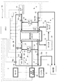
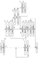
図1は、本実施形態に係る制御方法が適用された燃料電池システム1の構成を模式的に示す図である。先ず、燃料電池システム1全体の構成のうち、主に燃料電池スタック2により発電させるために必要な装置の構成について、図1を参照しながら説明する。
Hereinafter, an embodiment of the present invention will be described with reference to the drawings.
FIG. 1 is a diagram schematically illustrating a configuration of a
燃料電池システム1は、燃料電池スタック2と、燃料電池スタック2に燃料ガスとしての水素を供給するアノード系3と、燃料電池スタック2に酸化剤ガスとしての空気を供給するカソード系4と、燃料電池スタック2から排出されたガスの後処理を行う希釈器37と、燃料電池スタック2を冷却する冷却装置5と、燃料電池スタック2で発電した電力を蓄えるバッテリBと、ECU7と、燃料電池スタック2及びバッテリBからの電力の供給によって駆動する走行モータMと、を備える。燃料電池システム1は、走行モータMで走行する図示しない燃料電池車両に搭載される。
The
燃料電池スタック(以下、単に「スタック」という)2は、例えば、数十個から数百個のセルが積層されたスタック構造である。各燃料電池セルは、膜電極構造体(MEA)を一対のセパレータで挟持して構成される。膜電極構造体は、アノード電極(陰極)及びカソード電極(陽極)の2つの電極と、これら電極に挟持された固体高分子電解質膜とで構成される。通常、両電極は、固体高分子電解質膜に接して酸化・還元反応を行う触媒層と、この触媒層に接するガス拡散層とから形成される。このスタック2は、アノード電極側に形成されたアノード流路21に水素が供給され、カソード電極側に形成されたカソード流路22に酸素を含んだ空気が供給されると、これらの電気化学反応により発電する。
The fuel cell stack (hereinafter simply referred to as “stack”) 2 has a stack structure in which, for example, several tens to several hundreds of cells are stacked. Each fuel cell is configured by sandwiching a membrane electrode structure (MEA) between a pair of separators. The membrane electrode structure is composed of two electrodes, an anode electrode (cathode) and a cathode electrode (anode), and a solid polymer electrolyte membrane sandwiched between these electrodes. Usually, both electrodes are formed of a catalyst layer that performs an oxidation / reduction reaction in contact with the solid polymer electrolyte membrane and a gas diffusion layer in contact with the catalyst layer. In the
発電中のスタック2から取り出される出力電流は、電流制御器29を介してバッテリBや負荷(走行モータM及びエアコンプレッサ41等)に入力される。電流制御器29は、図示しないDC−DCコンバータを備えており、そのチョッピング動作によって発電中のスタック2の出力電流を制御する。特に後述の停止時充電処理やEGRディスチャージ処理では、電流制御器29は、スタック2の出力電流をバッテリBの充電電流とし、これを所定の電流指令値に制御しながらバッテリBに充電する。
The output current taken out from the
バッテリBは、スタック2で発電した電力や、走行モータMによって回生制動力として回収した電気エネルギーを蓄える。また、例えば燃料電池システムの起動時や車両の高負荷運転時には、バッテリBに蓄えられた電力はスタック2の出力を補うようにして負荷に供給される。
The battery B stores electric power generated by the
アノード系3は、水素タンク31と、水素タンク31からスタック2のアノード流路21の導入部に至る水素供給管32と、アノード流路21の排出部から希釈器37に至る水素排出管33と、水素排出管33から分岐し水素供給管32に至る水素還流管34と、を含んで構成される。水素を含んだガスの水素循環流路は、水素供給管32、アノード流路21、水素排出管33及び水素還流管34によって構成される。
The
水素タンク31は、水素ガスを高圧で貯蔵するタンク本体311と、タンク本体311から延びる水素供給管32に設けられた主止弁312と、を備える。
The
水素供給管32のうち、主止弁312より下流側には、水素タンク31から供給された新たな水素ガスを、スタック2へ向けて噴射するインジェクタ35が設けられている。なお以下では、水素供給管32のうち、インジェクタ35と主止弁312との間の区間を中圧部321という。発電中のスタック2のアノード流路21内の圧力(以下、「アノード圧」という)は、中圧部321内の圧力が十分に高い状態でインジェクタ35を開閉駆動することにより所定の目標圧に制御される。なお、主止弁312を閉じた後であっても、この中圧部321内に十分な量の水素ガスが残っている間は、インジェクタ35を開閉駆動することによってアノード圧を制御できる。
In the
水素還流管34には、水素排出管33側のガスを水素供給管32へ圧送し、水素循環流路内で水素を含んだガスを循環させる水素ポンプ36が設けられている。水素排出管33のうち、上記水素還流管34との接続部より下流側には、パージ弁33aが設けられている。水素循環流路内を循環するガスの水素濃度が低下すると、スタック2の発電効率が低下する。このため、パージ弁33aは、スタック2の発電中に適切なタイミングで開かれる。これにより、水素循環流路内のガスは、希釈器37へ排出される。
The
カソード系4は、エアコンプレッサ41と、エアコンプレッサ41からカソード流路22の導入部に至る空気供給管42と、カソード流路22の排出部から希釈器37に至る空気排出管43と、空気排出管43から分岐し空気供給管42に至る空気還流管45と、空気排出管43から分岐し水素供給管32及び希釈器37に至るスタックバイパス管48と、を含んで構成される。酸素を含んだガスの酸素循環流路は、空気供給管42、カソード流路22、空気排出管43及び空気還流管45によって構成される。
The
エアコンプレッサ41は、システム外の空気を、空気供給管42を介してスタック2のカソード流路22に空気を供給する。また、空気排出管43には、カソード流路22内の圧力を調整するための背圧弁43bが設けられている。発電中のスタック2のカソード流路22内の圧力(以下、「カソード圧」という)は、エアコンプレッサ41で空気を供給しながら背圧弁43bの開度を調整することにより、スタック2の発電状態に応じた適切な大きさに制御される。
The
空気還流管45には、空気排出管43側のガスを空気供給管42に圧送し、酸素循環流路内で酸素を含んだガスを循環させるEGRポンプ46が設けられている。空気供給管42のうち空気還流管45との接続部よりもエアコンプレッサ41側には、システム1の停止中にエアコンプレッサ41側からカソード流路22側へ外気が流入するのを防止する入口封止弁42aが設けられている。また、空気排出管43のうち空気還流管45との分岐部よりも希釈器37側には、システム1の停止中に希釈器37側からカソード流路22側へ外気が流入するのを防止する出口封止弁43aが設けられている。これら封止弁42a、43aは、後述のEGR停止処理(例えば、後述の図3参照)において、カソード流路22に酸素濃度の低い不活性ガスを充填した状態で閉じられ、スタック2の劣化を抑制する。
The
スタックバイパス管48には、エアコンプレッサ41から希釈器37へ流れる空気の流量を制御するバイパス弁48aと、エアコンプレッサ41から水素供給管32へ流れる空気の流量を制御する掃気弁48bと、が設けられている。バイパス弁48aは、例えば背圧弁43bを閉じており、空気排出管43から希釈ガスを希釈器37に供給できない場合に開かれ、エアコンプレッサ41の直下の空気を希釈器37に供給する。掃気弁48bは、スタック2による発電を停止している間に、水素循環流路内に残留する不純物をエアコンプレッサ41から供給した空気で排出する掃気処理を実行する際に開かれる。
The
希釈器37は、上述の背圧弁43b、及びバイパス弁48aを介して導入されたガスを希釈ガスとして、パージ弁33aを介して排出された水素を含んだガスを希釈し、システム外に排出する。
The
冷却装置5は、スタック2を経路に含む冷媒循環流路51と、冷媒循環流路51内の冷媒を所定の方向に圧送するウォータポンプ52と、冷媒循環流路51の一部となるラジエタ53と、ラジエタ53を通流する冷媒を冷却するラジエタファン54と、を備える。冷却装置5は、ウォータポンプ52によって冷媒を循環しスタック2と冷媒との熱交換を促進するとともに、ラジエタファン54によって冷媒を冷却することにより、スタック2を保護するために定められた上限温度を上回らないようにする。
The cooling device 5 includes a
ECU7は、燃料電池システム1を構成する各種装置を制御する電子制御ユニットであり、CPU、ROM、RAM、及び各種インターフェースなどの電子回路を含んで構成される。ECU7には、燃料電池システム1の状態を検出するため、アノード圧センサ27、カソード圧センサ28等の各種センサが接続されている。
The
アノード圧センサ27は、水素供給管32に設けられ、アノード圧を検出し、検出値に略比例した信号をECU7に送信する。カソード圧センサ28は、空気排出管43に設けられ、カソード圧を検出し、検出値に略比例した信号をECU7に送信する。
The
図示しない車両の運転席には、燃料電池システム1の状態を利用者に報知する表示装置としてのインフォメーションパネルPと、スタック2による発電の開始(すなわち、燃料電池システム1の起動)又はスタック2による発電の停止(すなわち、燃料電池システム1の停止)を指令するために運転者が操作するイグニッションスイッチIGとが設けられている。
In a driver's seat of a vehicle (not shown), an information panel P as a display device for notifying the user of the state of the
イグニッションスイッチIGは、燃料電池システム1が停止した状態で操作されると、システム1の起動を指令する信号を発生する。ECU7は、イグニッションスイッチIGからの起動指令信号を受信すると、システム起動処理を開始する。システム起動処理では、バッテリBに蓄えられた電力を利用して負荷を駆動し、スタック2を発電可能な状態にするとともに車両を走行する。また、スタック2が発電可能な状態になった後は、所定のタイミングで図示しないコンタクタを閉じ、スタック2とバッテリBや負荷とを電気的に接続し、システムの起動が完了する。
The ignition switch IG generates a signal for instructing activation of the
イグニッションスイッチIGは、燃料電池システム1が起動した状態で操作されると、システム1の停止を指令する信号を発生する。ECU7は、イグニッションスイッチIGからの停止指令信号を受信したことを契機として、後に図3を参照して詳細に説明するシステム停止処理を開始するとともに、上記インフォメーションパネルPにシステム停止処理の実行中であることを表示する。ECU7は、システム停止処理が完了すると、上記コンタクタを開いてスタック2とバッテリBや負荷とを電気的に遮断する。
When the ignition switch IG is operated in a state where the
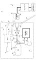
図2は、水素充填システムSの構成を示す図である。水素充填システムSは、上記燃料電池システム1を搭載した車両Vと、この車両Vに水素ガスを供給する水素ステーション9とを組み合わせて構成される。
FIG. 2 is a diagram showing a configuration of the hydrogen filling system S. As shown in FIG. The hydrogen filling system S is configured by combining a vehicle V on which the
水素ステーション9は、水素貯蔵タンク91と、ディスペンサ92とを備える。
水素貯蔵タンク91には、車両Vに供給するための水素が高圧で貯蔵されている。この水素貯蔵タンク91内の水素は、液体水素を気化したもの、改質装置により原料を改質することで製造されたもの、或いは電解装置によって製造されたものなどを圧縮機で圧縮したものが用いられる。
The
Hydrogen to be supplied to the vehicle V is stored in the
ディスペンサ92は、その水素充填ノズル93が車両Vに設けられた水素導入口82に差し込まれると、水素貯蔵タンク91から供給された水素を減圧し、好ましい流量に調整した上で水素充填ノズル93から水素を供給する。この水素充填ノズル93には、赤外線通信器94が設けられている。赤外線通信器94は、水素充填ノズル93を車両Vの水素導入口82に差し込むことにより、車両Vに搭載された後述の通信システム6との間で赤外線を介したデータ信号の送受信が可能となっている。
When the
次に、図2を参照して、燃料電池システム1全体の構成のうち主に水素タンク31に水素ガスを充填するために必要な装置の構成について説明する。
Next, with reference to FIG. 2, the structure of the apparatus required in order to mainly fill the
水素タンク31は、タンク本体311から延びる水素導入管313と、タンク圧力センサ317と、タンク温度センサ318と、をさらに備える。この水素導入管313は、一端側がタンク本体311に接続され、他端側が後述のリッドボックス81内に設けられた水素導入口82に接続されている。
The
水素導入管313には、逆止弁314,315と、充填経路遮断弁316とが設けられている。充填経路遮断弁316は、タンク本体311へのガスの流入及びタンク本体311からのガスの流出を遮断する。逆止弁314,315は、それぞれ、タンク本体311の近傍と水素導入口82の近傍に設けられ、タンク本体311側から車両Vの外側へ水素が逆流するのを防止する。
The
タンク圧力センサ317は、水素タンク31のうち水素導入管313内の水素圧力を検出し、検出値に略比例した検出信号をECU7に送信する。タンク温度センサ318は、水素タンク31のうちタンク本体311内の水素温度を検出し、検出値に略比例した検出信号をECU7に送信する。
The
リッドボックス81は、車両Vの側部後方に設けられており、その内部で水素導入口82を保護する。このリッドボックス81には、リッド83が回動可能に設けられている。水素ステーション9において、利用者はリッド83を開き水素導入口82を外部に露出させ、ディスペンサ92の水素充填ノズル93を水素導入口82に差し込み、水素を充填する。
The
燃料電池システム1は、上述の通信充填を実行するために通信システム6を備える。この通信システム6は、ECU7と、赤外線送信器66と、リッドスイッチ67と、を含んで構成される。
The
リッドスイッチ67は、リッドボックス81に設けられており、リッド83の開閉状態を検出する。リッドスイッチ67は、リッド83が閉じられリッドボックス81内に水素導入口82が保護された状態では、これを示す閉信号をECU7に送信し、リッド83が開かれ水素導入口82が外部に露出した状態では、これを示す開信号をECU7に送信する。なお、これら閉信号及び開信号のうち何れかは無信号としてもよい。
The
赤外線送信器66は、赤外線LED64とそのドライバ65で構成される。ドライバ65は、ECU7から送信されたデータ信号に基づいて赤外線LED64を点滅させる。
The
ECU7は、通信充填の実行時、ドライバ65によって赤外線LED64を点滅させることにより、タンク圧力センサ317及びタンク温度センサ318で検出された圧力及び温度に基づいて生成したデータ信号や、水素ガスの充填の停止を指令するための充填停止指令信号をステーション9側の赤外線通信器94へ送信する。
The
以上のように構成された通信システム6は、利用者によるリッド83の開閉を契機として起動/停止する。以下、通信システム6を起動し通信充填を実行する手順について説明する。
The
利用者が車両Vを停止し、イグニッションスイッチIGを停止操作した後、リッド83を開くと、リッドスイッチ67はこれを検出し、リッド83が開かれたことを示す開信号をECU7に送信する。これに応じてECU7は、赤外線送信器66への図示しないバッテリからの電力の供給を開始し、データ信号を送信可能な状態にする。その後、ステーション9側の水素充填ノズル93が車両Vの水素導入口82に差し込まれ、水素の充填と、車両Vとステーション9との間の通信が可能な状態になったことに応じて、充填経路遮断弁316を開き、通信充填を開始する。
After the user stops the vehicle V and stops the ignition switch IG, when the
通信充填の実行中、ECU7は、タンク圧力センサ317及びタンク温度センサ318で検出された圧力及び温度に基づいて生成した、現在の水素タンク31の状態を示すデータ信号を赤外線送信器66によってステーション9側へ送信する。ディスペンサ92は、赤外線通信器94によって車両Vから送信された上記データ信号を受信し、このデータ信号から現在の水素タンク31の状態を把握し、状態に応じて充填流量を調整しながら水素タンク31に水素を充填する。その後、ディスペンサ92は、受信したデータ信号に基づいて推定した水素タンク31内の水素ガス残量が所定の満充填閾値に達した場合や、予め定められた充填完了条件が満たされたことに応じて、水素の充填を終了する。
During execution of the communication filling, the
通信充填が適切に終了すると、利用者によって水素充填ノズル93が水素導入口82から抜き出され、そしてリッド83が閉じられる。リッド83が閉じられると、リッドスイッチ67はこれを検出し、リッド83が閉じられたことを示す閉信号をECU7に送信する。これに応じてECU7は、充填経路遮断弁316を閉じ、赤外線送信器66への電力の供給を停止する。
When the communication filling is properly completed, the
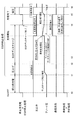
次に、図3を参照して、燃料電池システムの停止指令後に行うシステム停止処理の手順について説明する。
図3は、システム停止処理における各装置の制御手順を示すタイムチャートである。なお図3は、システムの停止指令後、システム停止処理を行っている間に通信充填の割り込みがなかった場合を示す。
Next, with reference to FIG. 3, the procedure of the system stop process performed after the stop command for the fuel cell system will be described.
FIG. 3 is a time chart showing the control procedure of each device in the system stop process. FIG. 3 shows a case where there is no communication filling interruption during the system stop process after the system stop command.
システム停止処理は、停止時充電処理と、停止後ディスチャージ工程に相当するEGR停止処理と、停止処理工程に相当する希釈処理及び冷却処理と、の4つの処理で構成される。 The system stop process includes four processes of a stop-time charging process, an EGR stop process corresponding to a post-stop discharge process, and a dilution process and a cooling process corresponding to the stop process.
停止時充電処理は、次回のシステムの起動に備えて、システムの停止指令後もスタックによる発電を継続し、発電した電力をバッテリに充電する処理である。この停止時充電処理は、システムの停止指令時におけるバッテリの残容量が不十分であると判断された場合にのみ、システムの停止指令後、直ちに実行される(例えば、後述の図5、7、及び9参照)。なお、図3のタイムチャートでは、システムの停止指令時にバッテリの残容量が十分であると判断され、停止時充電処理が行われなかった場合を示す。 The charging process at the time of stop is a process of continuing power generation by the stack even after the system stop command and charging the generated power to the battery in preparation for the next system startup. This stop-time charging process is executed immediately after the system stop command only when it is determined that the remaining battery capacity at the time of the system stop command is insufficient (for example, FIGS. 5 and 7 described later). And 9). Note that the time chart of FIG. 3 shows a case where it is determined that the remaining battery capacity is sufficient when the system stop command is issued, and the stop-time charging process is not performed.
EGR停止処理は、スタックの劣化を抑制するための処理であり、システムの停止指令後、システムが完全に停止するまでの間に行われる。このEGR停止処理は、図3に示すように、圧上げ処理(t1〜t2)と、EGRディスチャージ処理(t2〜t3)と、保圧処理(t3〜t4)と、の3つの処理で構成される。 The EGR stop process is a process for suppressing stack deterioration, and is performed after the system stop command until the system is completely stopped. As shown in FIG. 3, the EGR stop process is composed of three processes: a pressure increase process (t1 to t2), an EGR discharge process (t2 to t3), and a pressure holding process (t3 to t4). The
圧上げ処理は、EGRディスチャージ処理の実行に先立ち、予めアノード圧を好ましい圧力まで昇圧する処理である。より具体的には、圧上げ処理では、主止弁を開き中圧部に十分な圧力を確保した状態で、アノード圧が後述の目標圧になるように、アノード圧センサの出力に基づいてインジェクタをフィードバック制御する。 The pressure increasing process is a process of increasing the anode pressure to a preferable pressure in advance prior to the execution of the EGR discharge process. More specifically, in the pressure increasing process, the injector is based on the output of the anode pressure sensor so that the anode pressure becomes a target pressure described later with the main stop valve opened and sufficient pressure in the intermediate pressure portion. Feedback control.
EGRディスチャージ処理は、スタックの劣化を防止するため、システムを完全に停止させる前にスタックのカソード流路に残留する酸素を消費する処理である。EGRディスチャージ処理では、アノード系の装置については、主止弁を開いた状態でインジェクタによってアノード圧を予め定められた目標圧(以下、「ディスチャージ時目標圧」という)に制御しながら、水素ポンプによって水素循環流路内の水素ガスを循環させる。一方、カソード系の装置については、入口封止弁及び出口封止弁を閉じた状態でコンプレッサを駆動することにより、カソード圧を所定の目標圧に維持する。また、EGRポンプを駆動することにより、酸素循環流路内でガスを循環させることにより、酸素循環流路内の酸素濃度を徐々に低下させる。EGRディスチャージ処理では、水素循環流路及び酸素循環流路を上述のような状態に維持しながらスタックによる発電及びディスチャージを所定時間にわたって行い、酸素循環流路内の酸素濃度を低下させる。EGRディスチャージ処理は、酸素循環流路内の酸素濃度が所定濃度まで低下するまで、又は酸素濃度が所定濃度まで低下したと判断できる程度の時間が経過するまで実行される。なお、このEGRディスチャージ処理を実行している間にスタックから取り出された発電電流は、例えばバッテリに供給される。 The EGR discharge process is a process of consuming oxygen remaining in the cathode flow path of the stack before completely shutting down the system in order to prevent deterioration of the stack. In the EGR discharge process, the anode system device is controlled by a hydrogen pump while controlling the anode pressure to a predetermined target pressure (hereinafter referred to as “target pressure at discharge”) by an injector with the main stop valve opened. The hydrogen gas in the hydrogen circulation channel is circulated. On the other hand, in the cathode system device, the cathode pressure is maintained at a predetermined target pressure by driving the compressor with the inlet sealing valve and the outlet sealing valve closed. Further, by driving the EGR pump, gas is circulated in the oxygen circulation channel, thereby gradually decreasing the oxygen concentration in the oxygen circulation channel. In the EGR discharge process, power generation and discharge by the stack are performed for a predetermined time while maintaining the hydrogen circulation channel and the oxygen circulation channel in the above-described state, thereby reducing the oxygen concentration in the oxygen circulation channel. The EGR discharge process is executed until the oxygen concentration in the oxygen circulation channel decreases to a predetermined concentration, or until a time sufficient to determine that the oxygen concentration has decreased to the predetermined concentration has elapsed. Note that the generated current extracted from the stack during the execution of the EGR discharge process is supplied to, for example, a battery.
保圧処理は、EGRディスチャージ処理の終了後に、アノード圧をさらに昇圧する処理である。より具体的には、保圧処理では、主止弁を開いた状態でインジェクタによって上述のディスチャージ時目標圧よりも高い所定の保圧時目標圧までアノード圧を昇圧する。 The pressure holding process is a process of further increasing the anode pressure after the end of the EGR discharge process. More specifically, in the pressure holding process, the anode pressure is increased to a predetermined pressure holding target pressure that is higher than the above-described discharge target pressure by the injector with the main stop valve opened.
以上のような手順でEGR停止処理を実行することにより、スタックのカソード流路には酸素濃度の低い不活性ガスが充填され、アノード流路は水素ガスによって高圧に維持される。これにより、カソード側からの残留酸素の透過が極力抑制され、スタックの劣化を抑制できる。 By executing the EGR stop process according to the above procedure, the cathode flow path of the stack is filled with an inert gas having a low oxygen concentration, and the anode flow path is maintained at a high pressure by hydrogen gas. Thereby, the permeation | transmission of the residual oxygen from a cathode side is suppressed as much as possible, and deterioration of a stack can be suppressed.
なお、以上のEGR停止処理は、上記停止時充電処理と同様にスタックによる発電及びディスチャージを伴う処理であるため、基本的には上記停止時充電処理と並行して行うことはできない。そこで本実施形態では、システムの停止指令後、停止時充電処理が行われた場合には、この停止時充電処理が完了した後にEGR停止処理を開始する。また、停止時充電処理が行われなかった場合には、システムの停止指令後、直ちに実行される。 Note that the EGR stop process described above is a process involving power generation and discharge by the stack, similar to the above-described stop-time charge process, and therefore cannot be performed in parallel with the stop-time charge process. Therefore, in the present embodiment, when the stop-time charging process is performed after the system stop command, the EGR stop process is started after the stop-time charging process is completed. Further, when the stop-time charging process is not performed, it is executed immediately after the system stop command.
希釈処理は、システムの停止指令時に希釈器内に残留していた水素ガスを希釈し、希釈器内の水素濃度を規定の濃度まで所定時間かけて低下させる処理である。この希釈処理は、スタックへ積極的に水素ガスを供給する必要が無く、かつコンプレッサを駆動しており希釈器内に希釈ガスを導入できる状態であれば実行できる処理であるため、上記停止時充電処理及びEGR停止処理と並行して実行できる。したがって本実施形態では、システムの停止指令後、直ちに希釈処理を開始する。 The dilution process is a process for diluting the hydrogen gas remaining in the diluter at the time of system stop command and reducing the hydrogen concentration in the diluter to a specified concentration over a predetermined time. This dilution process is a process that can be performed as long as there is no need to actively supply hydrogen gas to the stack, and the compressor is driven and dilution gas can be introduced into the diluter. It can be executed in parallel with the process and the EGR stop process. Therefore, in this embodiment, the dilution process is started immediately after the system stop command.
より具体的には、希釈処理では、図3に示すように、コンプレッサを駆動した状態で、背圧弁、及びスタックバイパス弁等を適宜開閉することにより、スタックから排出されたガスやコンプレッサの直下のガスを希釈器に導入し、これを希釈ガスとして希釈器内の水素を希釈する。なお、出口封止弁を閉じている間は、背圧弁を開いても希釈器に希釈ガスを導入できない。このため、EGRディスチャージ処理を行っている間は、スタックバイパス弁を適宜開閉することにより、希釈ガスを希釈器に導入する。 More specifically, in the dilution process, as shown in FIG. 3, by opening and closing the back pressure valve, the stack bypass valve, and the like as needed while the compressor is driven, Gas is introduced into a diluter, and this is used as a diluting gas to dilute hydrogen in the diluter. In addition, while the outlet sealing valve is closed, the dilution gas cannot be introduced into the diluter even if the back pressure valve is opened. For this reason, during the EGR discharge process, the diluent gas is introduced into the diluter by appropriately opening and closing the stack bypass valve.
冷却処理は、ウォータポンプ及びラジエタファンを適宜駆動することにより(図3参照)、スタックの温度を例えば常温まで所定時間かけて低下させる処理である。この冷却処理は、スタックへ積極的に水素ガスを供給する必要が無く、かつウォータポンプやラジェタファンなどスタックによる発電や希釈器の状態とは無関係の装置を駆動することによって実行する処理であるため、上記停止時充電処理、EGR停止処理、及び希釈処理と並行して実行できる。したがって本実施形態では、システムの停止指令後、直ちに冷却処理を開始する。 The cooling process is a process of reducing the stack temperature to, for example, room temperature over a predetermined time by appropriately driving the water pump and the radiator fan (see FIG. 3). This cooling process is a process executed by driving a device that does not need to actively supply hydrogen gas to the stack and is independent of the state of the power generation and diluter by the stack, such as a water pump and a radiator fan. It can be executed in parallel with the stop charging process, EGR stop process, and dilution process. Therefore, in this embodiment, the cooling process is started immediately after the system stop command.
次に、図3を参照して説明したシステム停止処理を行っている間に通信充填の割り込みが生じた場合の具体的な制御の手順について、3つの実施例を説明する。 Next, three examples of specific control procedures when a communication filling interruption occurs during the system stop process described with reference to FIG. 3 will be described.
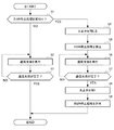
図4は、システムの停止指令後に通信充填の要求があった場合にECUによって実行される実施例1の割込制御の手順を示すフローチャートである。図4の処理は、システムの停止指令後であって、利用者によって通信充填の開始を指令する所定の操作が行われたこと(例えば、リッドが開かれたことや、車両の水素導入口にステーションの水素充填ノズルが挿入されたこと等)を契機として開始する。 FIG. 4 is a flowchart illustrating a procedure of interrupt control according to the first embodiment that is executed by the ECU when there is a request for communication filling after a system stop command. The processing of FIG. 4 is after the system stop command, and a predetermined operation for commanding the start of communication filling is performed by the user (for example, when the lid is opened or the hydrogen inlet of the vehicle is installed). It starts when the hydrogen filling nozzle of the station is inserted.
S1では、現在、EGR停止処理の実行中であるか否かを判別する。S1の判別がYESであり現在EGR停止処理の実行中である場合には、S4に移り、S1の判別がNOであり現在EGR停止処理の実行中でない場合には、S2に移る。 In S1, it is determined whether or not an EGR stop process is currently being executed. If the determination in S1 is YES and the EGR stop process is currently being executed, the process proceeds to S4. If the determination in S1 is NO and the EGR stop process is not currently being executed, the process proceeds to S2.
S2では、通信充填を実行し、S3に移る。S2では、より具体的には、高圧タンクの現在の状態に関するデータ信号をステーション側へ送信し、ステーション側は、受信したデータ信号に基づいて最適な態様で水素ガスを充填する。なおこの時、希釈処理や冷却処理が実行中である場合には、希釈処理や冷却処理と並行して通信充填を実行する。S3では、通信充填が完了したか否かを判別する。S3の判別がNOである場合にはS2に戻って通信充填を継続し、YESである場合には、この処理を終了する。 In S2, communication filling is executed, and the process proceeds to S3. More specifically, in S2, a data signal regarding the current state of the high-pressure tank is transmitted to the station side, and the station side is filled with hydrogen gas in an optimum manner based on the received data signal. At this time, when the dilution process or the cooling process is being executed, the communication filling is executed in parallel with the dilution process or the cooling process. In S3, it is determined whether or not communication filling is completed. If the determination in S3 is NO, the process returns to S2 and communication filling is continued, and if the determination is YES, this process ends.
S4では、主止弁を閉じ、高圧タンクからの水素ガスの流出を停止し、S5に移る。これにより、高圧タンクの状態変動を最小限にし、赤外線送信器から送信される高圧タンクの状態に関するデータ信号の精度を高くできる。 In S4, the main stop valve is closed, the outflow of hydrogen gas from the high-pressure tank is stopped, and the process proceeds to S5. Thereby, the state fluctuation of the high-pressure tank can be minimized, and the accuracy of the data signal relating to the state of the high-pressure tank transmitted from the infrared transmitter can be increased.
S5では、EGR停止処理の実行を禁止し、S6に移る。これにより、後述のS9において再び許可されるまで、現在実行中のEGR停止処理は中断される。ここで、EGR停止処理の中断とは、具体的には、インジェクタによるアノード圧制御、水素ポンプによる水素ガスの循環、EGRポンプによる空気の循環、及びスタックのディスチャージの全て又は一部を一時的に停止することをいう。 In S5, execution of the EGR stop process is prohibited, and the process proceeds to S6. As a result, the EGR stop process that is currently being executed is suspended until it is permitted again in S9 described later. Here, the interruption of the EGR stop process specifically means that all or part of anode pressure control by the injector, hydrogen gas circulation by the hydrogen pump, air circulation by the EGR pump, and stack discharge are temporarily. It means stopping.
S6では、通信充填を実行し、S7に移る。通信充填では、高圧タンクの状態に関するデータ信号を赤外線送信器からステーション側に送信しながら、ステーション側から供給された水素ガスを高圧タンクに充填する。S7では、通信充填が完了したか否かを判別する。S7の判別がNOである場合にはS6に戻って通信充填を継続し、YESである場合には、S8に移る。S8では、S4において閉じた主止弁を再び開き、S9に移る。S9では、中断していたEGR停止処理の実行を許可し、この処理を終了する。 In S6, communication filling is executed, and the process proceeds to S7. In communication filling, a high-pressure tank is filled with hydrogen gas supplied from the station side while transmitting a data signal regarding the state of the high-pressure tank from the infrared transmitter to the station side. In S7, it is determined whether or not communication filling is completed. If the determination in S7 is NO, the process returns to S6 to continue communication filling, and if YES, the process moves to S8. In S8, the main stop valve closed in S4 is opened again, and the process proceeds to S9. In S9, execution of the interrupted EGR stop process is permitted, and this process ends.
図5は、実施例1の割込制御の具体的な例を示すタイムチャートである。
図5では、時刻t0においてシステムの停止指令があった後、時刻t0から停止時充電処理と、冷却処理と、希釈処理とを並行して開始し、その後時刻t1において停止時充電処理が終了したことに伴いEGR停止処理を開始した場合を示す。
FIG. 5 is a time chart illustrating a specific example of interrupt control according to the first embodiment.
In FIG. 5, after the system stop command is issued at time t0, the stop-time charging process, the cooling process, and the dilution process are started in parallel from time t0, and then the stop-time charging process is completed at time t1. The case where the EGR stop process is started accordingly is shown.
上述のようにEGR停止処理は、圧上げ処理とEGRディスチャージ処理と保圧処理との3つの処理から成る。
時刻t1〜t2の間では圧上げ処理が実行され、これによりアノード圧は、ディスチャージ時目標圧まで昇圧される。圧上げ処理が完了した後、時刻t2からは、EGRディスチャージ処理が開始する。これにより、アノード圧がディスチャージ時目標圧に維持されながら、カソード側に残留する酸素が消費される。
As described above, the EGR stop process includes three processes including a pressure increasing process, an EGR discharge process, and a pressure holding process.
During the time t1 to t2, a pressure increasing process is executed, whereby the anode pressure is increased to the target pressure during discharge. After the pressurization process is completed, the EGR discharge process starts from time t2. Thus, oxygen remaining on the cathode side is consumed while the anode pressure is maintained at the target pressure during discharge.
時刻t2においてEGRディスチャージ処理を開始してから、時刻t3では、利用者により通信充填の開始を指令する操作が行われる。これにより、時刻t3から、図4に示す割込制御が開始する。したがって、時刻t3では、主止弁が閉じられ(S4参照)、通信充填が開始される(S6参照)。また時刻t3では、主止弁が閉じられるとともに実行中のEGRディスチャージ処理が中断されるため(S5参照)、図5に示すようにアノード圧は徐々に低下する。このように、主止弁を閉じた後に通信充填を開始することにより通信充填中に赤外線送信器から送信される高圧タンクの状態に関するデータ信号の精度を高くできる。また、通信充填の開始を指令する操作が行われると、主止弁が閉じられた後、EGRディスチャージ処理は中断されるが、希釈処理及び冷却処理は通信充填と並行して実行される。 After starting the EGR discharge process at time t2, at time t3, an operation to instruct the start of communication filling is performed by the user. Thereby, the interrupt control shown in FIG. 4 starts from time t3. Therefore, at time t3, the main stop valve is closed (see S4), and communication filling is started (see S6). At time t3, since the main stop valve is closed and the EGR discharge process being executed is interrupted (see S5), the anode pressure gradually decreases as shown in FIG. Thus, by starting communication filling after closing the main stop valve, the accuracy of the data signal regarding the state of the high-pressure tank transmitted from the infrared transmitter during communication filling can be increased. When an operation for commanding the start of communication filling is performed, the EGR discharge process is interrupted after the main stop valve is closed, but the dilution process and the cooling process are executed in parallel with the communication filling.
その後時刻t4では、通信充填が完了したことに伴い、主止弁を開き(S8参照)、さらに時刻t3から中断していたEGRディスチャージ処理を再開する(S9参照)。その後、時刻t5では、EGRディスチャージ処理が完了したことに応じて保圧処理が開始し、時刻t6では、保圧処理が完了する。これにより、燃料電池システムは完全に停止する。 After that, at time t4, as the communication filling is completed, the main stop valve is opened (see S8), and the EGR discharge process suspended from time t3 is resumed (see S9). Thereafter, the pressure holding process starts in response to the completion of the EGR discharge process at time t5, and the pressure holding process is completed at time t6. As a result, the fuel cell system is completely stopped.
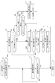
図6は、システムの停止指令後に通信充填の要求があった場合にECUによって実行される実施例2の割込制御の具体的な手順を示すフローチャートである。図6の処理は、図4の処理と同様に、システムの停止指令後であって利用者によって通信充填の開始を指令するため所定の操作が行われたことを契機として開始する。なお、図6の処理において、S1〜S4の処理は図4と同じであるので、詳細な説明は省略する。実施例2の割込制御は、S4において主止弁を閉じた後も引き続き可能な限りEGR停止処理を継続する点で実施例1の割込制御と異なる。 FIG. 6 is a flowchart illustrating a specific procedure of the interrupt control according to the second embodiment that is executed by the ECU when there is a request for communication filling after a system stop command. The process of FIG. 6 is started when a predetermined operation is performed by the user to instruct the start of communication filling after the system stop instruction, similarly to the process of FIG. In addition, in the process of FIG. 6, since the process of S1-S4 is the same as FIG. 4, detailed description is abbreviate | omitted. The interrupt control of the second embodiment is different from the interrupt control of the first embodiment in that the EGR stop process is continued as much as possible after the main stop valve is closed in S4.
S4において主止弁を閉じた後、S15では、現在EGR停止処理が禁止された状態であることを示す禁止フラグが“1”であるか否かを判別する。この禁止フラグは、図6の処理を開始した当初は“0”に設定され、後述のS18の処理において“1”に設定される。S4の判別がNOである場合、引き続きEGR停止処理を継続して実行できるか否かを判断すべく、S16に移る。 After the main stop valve is closed in S4, in S15, it is determined whether or not the prohibition flag indicating that the EGR stop process is currently prohibited is “1”. This prohibition flag is initially set to “0” when the process of FIG. 6 is started, and is set to “1” in the process of S18 described later. If the determination in S4 is NO, the process proceeds to S16 to determine whether or not the EGR stop process can be continued.
S16では、アノード圧センサによって検出されたアノード圧が、所定の下限圧より低いか否かを判別する。この下限圧は、ディスチャージ時目標圧よりもやや低めに設定される。主止弁を閉じると、高圧タンクから中圧部への水素ガスの供給は停止するため、インジェクタを開きアノード圧を高める度に中圧部の圧力は低下する。このため、S4において主止弁を閉じた後もEGR停止処理を継続して実行すると、インジェクタによってアノード圧を上記目標圧に維持できなくなり、次第にアノード圧が低下する。S16では、このような主止弁を閉じた後のアノード圧の低下を検出することによって、EGR停止処理を中断するタイミングを判断する。 In S16, it is determined whether or not the anode pressure detected by the anode pressure sensor is lower than a predetermined lower limit pressure. This lower limit pressure is set slightly lower than the target pressure during discharge. When the main stop valve is closed, the supply of hydrogen gas from the high-pressure tank to the intermediate pressure portion stops, so that the pressure in the intermediate pressure portion decreases each time the injector is opened and the anode pressure is increased. For this reason, if the EGR stop process is continuously executed even after the main stop valve is closed in S4, the anode pressure cannot be maintained at the target pressure by the injector, and the anode pressure gradually decreases. In S16, the timing at which the EGR stop process is interrupted is determined by detecting a decrease in the anode pressure after the main stop valve is closed.
S16の判別がYESである場合には、S17に移り、EGR停止処理の実行を禁止した後、S18に移る。S18では、EGR停止処理が禁止された状態を明示すべく、禁止フラグを“1”にセットし、S20に移る。 If the determination in S16 is YES, the process moves to S17, prohibits execution of the EGR stop process, and then moves to S18. In S18, in order to clarify the state in which the EGR stop process is prohibited, the prohibition flag is set to “1”, and the process proceeds to S20.
S16の判別がNOである場合には、S19に移る。S19では、EGRディスチャージ処理が完了したか否かを判別する。S19の判別がYESの場合には、S17に移り、上述のようにEGR停止処理の実行を禁止する。上述のように、EGR停止処理では、EGRディスチャージ処理が終了した後、保圧処理を実行する。しかしこの保圧処理では、アノード圧を保圧時目標圧まで昇圧するために、主止弁を開く必要がある。このため、EGRディスチャージ処理が終了した場合には、引き続き保圧処理を行うことなく中断する。 If the determination in S16 is NO, the process moves to S19. In S19, it is determined whether or not the EGR discharge process is completed. If the determination in S19 is YES, the process moves to S17, and the execution of the EGR stop process is prohibited as described above. As described above, in the EGR stop process, the pressure holding process is executed after the EGR discharge process is completed. However, in this pressure holding process, it is necessary to open the main stop valve in order to increase the anode pressure to the target pressure during pressure holding. For this reason, when the EGR discharge process is completed, the process continues without performing the pressure holding process.
S15の判別がYESの場合又はS18において禁止フラグを“1”にセットした場合には、S20に移り、通信充填を実行し、S21に移る。S21では、通信充填が完了したか否かを判別する。S21の判別がNOである場合には、S15に戻る。これにより、可能な限り主止弁を閉じた後も引き続き可能な限りEGR停止処理と通信充填処理とが並行して実行される。 If the determination in S15 is YES or if the prohibition flag is set to “1” in S18, the process proceeds to S20, communication filling is performed, and the process proceeds to S21. In S21, it is determined whether or not communication filling is completed. If the determination in S21 is NO, the process returns to S15. As a result, even after the main stop valve is closed as much as possible, the EGR stop process and the communication filling process are executed in parallel as much as possible.
S21の判別がYESである場合、すなわち通信充填が終了した場合には、S22に移り、主止弁を開き、S23に移る。S23では、禁止フラグが“1”であるか否かを判別する。S23の判別がYESの場合、すなわち通信充填を行っている間にEGR停止処理を中断した場合には、S24に移り、中断していたEGR停止処理の実行を許可し、この処理を終了する。S23の判別がNOの場合、すなわちEGR停止処理を中断する前に通信充填が終了した場合には、引き続きEGR停止処理を継続すべく、この処理を終了する。 If the determination in S21 is YES, that is, if communication filling is completed, the process proceeds to S22, the main stop valve is opened, and the process proceeds to S23. In S23, it is determined whether or not the prohibition flag is “1”. If the determination in S23 is YES, that is, if the EGR stop process is interrupted while performing communication filling, the process proceeds to S24, where the execution of the interrupted EGR stop process is permitted, and this process ends. If the determination in S23 is NO, that is, if the communication filling is completed before the EGR stop process is interrupted, this process is ended to continue the EGR stop process.
図7は、実施例2の割込制御の具体的な例を示すタイムチャートである。
図7では、時刻t0においてシステムの停止指令があった後、時刻t0から停止時充電処理と、冷却処理と、希釈処理とを並行して開始し、その後時刻t1において停止時充電処理が終了したことに伴いEGR停止処理を開始した場合を示す。
FIG. 7 is a time chart illustrating a specific example of interrupt control according to the second embodiment.
In FIG. 7, after the system stop command is issued at time t0, the stop-time charging process, the cooling process, and the dilution process are started in parallel from time t0, and then the stop-time charging process is completed at time t1. The case where the EGR stop process is started accordingly is shown.
時刻t1〜t2の間では圧上げ処理が実行され、これによりアノード圧は、ディスチャージ時目標圧まで昇圧される。圧上げ処理が完了した後、時刻t2からは、EGRディスチャージ処理が開始する。これにより、アノード圧がディスチャージ時目標圧に維持されながら、カソード側に残留する酸素が消費される。 During the time t1 to t2, a pressure increasing process is executed, whereby the anode pressure is increased to the target pressure during discharge. After the pressurization process is completed, the EGR discharge process starts from time t2. Thus, oxygen remaining on the cathode side is consumed while the anode pressure is maintained at the target pressure during discharge.
時刻t2においてEGRディスチャージ処理を開始してから、時刻t3では、利用者により通信充填の開始を指令する操作が行われる。これにより、時刻t3から、図6に示す割込制御が開始する。したがって、時刻t3では主止弁が閉じられ(S4参照)、その後はアノード圧が下限圧より低下するか(S16参照)又はEGRディスチャージ処理が終了するまで(S19参照)、通信充填とEGRディスチャージ処理とが並行して実行される。なお、時刻t3以降は、主止弁を閉じた状態でEGRディスチャージ処理を行っているので、アノード圧は徐々に低下する。 After starting the EGR discharge process at time t2, at time t3, an operation to instruct the start of communication filling is performed by the user. Thereby, the interrupt control shown in FIG. 6 starts from time t3. Therefore, at time t3, the main stop valve is closed (see S4), and thereafter, until the anode pressure falls below the lower limit pressure (see S16) or the EGR discharge process ends (see S19), the communication filling and the EGR discharge process. Are executed in parallel. After time t3, the EGR discharge process is performed with the main stop valve closed, so the anode pressure gradually decreases.
時刻t4では、EGRディスチャージ処理が終了したことに応じて、EGR停止処理の保圧処理は中断される(S19、S17参照)。その後、時刻t5において通信充填が完了したことに応じて(S21参照)、主止弁が開かれ(S22参照)、時刻t4から中断していたEGR停止処理の保圧処理が再開される(S24参照)。時刻t6では、保圧処理が完了し、これにより、燃料電池システムは完全に停止する。 At time t4, the pressure holding process of the EGR stop process is interrupted in response to the end of the EGR discharge process (see S19 and S17). Thereafter, in response to completion of communication filling at time t5 (see S21), the main stop valve is opened (see S22), and the pressure holding process of the EGR stop process suspended from time t4 is resumed (S24). reference). At time t6, the pressure holding process is completed, whereby the fuel cell system is completely stopped.
図8は、システムの停止指令後に通信充填の要求があった場合にECUによって実行される実施例3の割込制御の具体的な手順を示すフローチャートである。図8の処理は、図4や図6の処理と同様に、システムの停止指令後であって利用者によって通信充填の開始を指令するため所定の操作が行われたことを契機として開始する。なお、図8の処理において、S1〜S4、S15〜S24の処理は図6と同じであるので、詳細な説明は省略する。実施例3の割込制御は、S4において主止弁を閉じる前に、S31において圧上げ処理を実行する点で実施例2の割込制御と異なる。 FIG. 8 is a flowchart illustrating a specific procedure of interrupt control according to the third embodiment that is executed by the ECU when there is a request for communication filling after a system stop command. The process of FIG. 8 is started when a predetermined operation is performed after the system stop command and the user commands the start of communication filling, similarly to the processes of FIGS. 4 and 6. In addition, in the process of FIG. 8, since the process of S1-S4 and S15-S24 is the same as FIG. 6, detailed description is abbreviate | omitted. The interrupt control of the third embodiment is different from the interrupt control of the second embodiment in that the pressure increasing process is executed in S31 before the main stop valve is closed in S4.
S1において、EGR停止処理が実行中であると判別された場合、S31に移る。S31では、圧上げ処理を実行し、S4に移り、主止弁を閉じる。より具体的には、S31では、主止弁を閉じる前であって中圧部の圧力が十分に高い状態でインジェクタを駆動し、上述のディスチャージ時目標圧よりも高く設定された閉弁前目標圧までアノード圧を昇圧する。このように主止弁を閉じる前に圧上げ処理を実行し、アノード圧を通常の目標圧よりも高くすることにより、主止弁を閉じた状態でも長い時間にわたってEGRディスチャージ処理を継続して実行することができる。 If it is determined in S1 that the EGR stop process is being executed, the process proceeds to S31. In S31, a pressure increasing process is executed, and the process proceeds to S4 to close the main stop valve. More specifically, in S31, before closing the main stop valve, the injector is driven in a state where the pressure of the intermediate pressure portion is sufficiently high, and the target before closing that is set higher than the target pressure at the time of discharge described above. The anode pressure is increased to the pressure. In this way, the pressure increasing process is executed before closing the main stop valve, and the anode pressure is made higher than the normal target pressure, so that the EGR discharge process is continuously executed for a long time even when the main stop valve is closed. can do.
図9は、実施例3の割込制御の具体的な例を示すタイムチャートである。
図9では、時刻t0においてシステムの停止指令があった後、時刻t0から停止時充電処理と、冷却処理と、希釈処理とを並行して開始し、その後時刻t1において停止時充電処理が終了したことに伴いEGR停止処理を開始した場合を示す。
FIG. 9 is a time chart illustrating a specific example of interrupt control according to the third embodiment.
In FIG. 9, after the system stop command is issued at time t0, the stop-time charging process, the cooling process, and the dilution process are started in parallel from time t0, and then the stop-time charging process is completed at time t1. The case where the EGR stop process is started accordingly is shown.
時刻t1〜t2の間では圧上げ処理が実行され、これによりアノード圧は、ディスチャージ時目標圧まで昇圧される。圧上げ処理が完了した後、時刻t2からは、EGRディスチャージ処理が開始する。これにより、アノード圧がディスチャージ時目標圧に維持されながら、カソード側に残留する酸素が消費される。 During the time t1 to t2, a pressure increasing process is executed, whereby the anode pressure is increased to the target pressure during discharge. After the pressurization process is completed, the EGR discharge process starts from time t2. Thus, oxygen remaining on the cathode side is consumed while the anode pressure is maintained at the target pressure during discharge.
時刻t2においてEGRディスチャージ処理を開始してから、時刻t3では、利用者により通信充填の開始を指令する操作が行われる。これにより、時刻t3から、図8に示す割込制御が開始する。したがって、時刻t3では、圧上げ処理が実行され(S31参照)、主止弁が閉じられ(S4参照)、その後はアノード圧が下限圧より低下するか(S16参照)又はEGRディスチャージ処理が終了するまで(S19参照)、通信充填とEGRディスチャージ処理とが並行して実行される。なお、時刻t3以降は、主止弁を閉じた状態でEGRディスチャージ処理を行っているので、アノード圧は徐々に低下する。ただし、主止弁を閉じた時点では、図7の例と比較して十分なアノード圧が確保されているため、図7の例よりも長い時間にわたってEGRディスチャージ処理と通信充填とを並行して実行できる。 After starting the EGR discharge process at time t2, at time t3, an operation to instruct the start of communication filling is performed by the user. Thereby, the interrupt control shown in FIG. 8 starts from time t3. Therefore, at time t3, the pressure increasing process is executed (see S31), the main stop valve is closed (see S4), and then the anode pressure is lower than the lower limit pressure (see S16) or the EGR discharge process is ended. Until (see S19), communication filling and EGR discharge processing are executed in parallel. After time t3, the EGR discharge process is performed with the main stop valve closed, so the anode pressure gradually decreases. However, when the main stop valve is closed, a sufficient anode pressure is secured as compared with the example of FIG. 7, and therefore, the EGR discharge process and the communication filling are performed in parallel for a longer time than the example of FIG. Can be executed.
時刻t4では、EGRディスチャージ処理が終了したことに応じて、EGR停止処理の保圧処理は中断される(S19、S17参照)。その後、時刻t5において通信充填が完了したことに応じて(S21参照)、主止弁が開かれ(S22参照)、時刻t4から中断していたEGR停止処理の保圧処理が再開される(S24参照)。時刻t6では、保圧処理が完了し、これにより、燃料電池システムは完全に停止する。 At time t4, the pressure holding process of the EGR stop process is interrupted in response to the end of the EGR discharge process (see S19 and S17). Thereafter, in response to completion of communication filling at time t5 (see S21), the main stop valve is opened (see S22), and the pressure holding process of the EGR stop process suspended from time t4 is resumed (S24). reference). At time t6, the pressure holding process is completed, whereby the fuel cell system is completely stopped.
以上本発明の一実施形態について説明したが、本発明はこれに限らない。
例えば、上記実施形態では、入口封止弁42aと出口封止弁43aとを備えた燃料電池システム1に本発明の制御方法を適用した例について説明したが、本発明はこれに限らない。これら封止弁を備えないシステムでは、上記EGR停止処理の替わりに、エアコンプレッサから極低流量の空気を供給しながら、アノード圧を上記EGRディスチャージ時目標圧よりも低く維持し、低ストイキ発電を所定時間にわたって行う場合がある。本発明の制御方法は、このような燃料電池システムに対しても適用できる。ただしこの場合、アノード圧はEGRディスチャージ時目標圧よりも低く維持するため、実施例2や3で説明したように、通信充填とこの低ストイキ発電とを並行して行うことは難しいと考えられる。したがって、このような燃料電池システムに本発明を適用する場合、実施例1の割込制御が特に好ましい。
Although one embodiment of the present invention has been described above, the present invention is not limited to this.
For example, in the above embodiment, the example in which the control method of the present invention is applied to the
1…燃料電池システム
2…スタック(燃料電池)
21…アノード流路
22…カソード流路
3…アノード系
31…水素タンク
311…タンク本体(貯蔵容器)
312…主止弁(開閉弁)
32…水素供給管(燃料ガス供給路、水素循環流路)
33…水素排出管(水素循環流路)
34…水素還流管(水素循環流路)
35…インジェクタ(燃料ガスインジェクタ)
4…カソード系
42…空気供給管(酸素循環流路)
43…空気排出管(酸素循環流路)
45…空気還流管(酸素循環流路)
66…赤外線送信器(送信手段)
IG…イグニッションスイッチ
1 ...
DESCRIPTION OF
312 ... Main stop valve (open / close valve)
32 ... Hydrogen supply pipe (fuel gas supply path, hydrogen circulation path)
33 ... Hydrogen discharge pipe (hydrogen circulation flow path)
34 ... Hydrogen reflux pipe (hydrogen circulation flow path)
35 ... Injector (fuel gas injector)
4 ...
43 ... Air discharge pipe (oxygen circulation flow path)
45 ... Air reflux pipe (oxygen circulation flow path)
66 ... Infrared transmitter (transmission means)
IG ... Ignition switch
Claims (6)
燃料ガスを貯蔵する貯蔵容器と、
前記貯蔵容器と前記燃料電池とを接続する燃料ガス供給路と、
前記燃料ガス供給路に設けられた開閉弁と、
前記貯蔵容器の状態を示すデータ信号を外部へ送信する送信手段と、を備えた燃料電池システムの制御方法であって、
前記制御方法は、
前記燃料電池システムへの停止指令後に、前記開閉弁を開き、前記燃料電池へ燃料ガスを供給し、前記燃料電池による発電及びディスチャージを継続する停止後ディスチャージ工程と、
前記貯蔵容器への燃料ガスの充填指令が出力されたことに応じて、前記貯蔵容器の状態を示すデータ信号を外部の燃料供給源に送信しながら、当該外部の燃料供給源から供給された燃料ガスを前記貯蔵容器に充填する充填工程と、
前記停止後ディスチャージ工程を行っている間に前記充填指令が出力された場合には、前記開閉弁を閉じるとともに前記停止後ディスチャージ工程を中断した後に、前記充填工程を開始する切替工程と、
前記充填工程が完了した後、前記中断した停止後ディスチャージ工程を再開する停止後ディスチャージ再開工程と、を含むことを特徴とする燃料電池システムの制御方法。 A fuel cell that generates electricity when fuel gas and oxidant gas are supplied; and
A storage container for storing fuel gas;
A fuel gas supply path connecting the storage container and the fuel cell;
An on-off valve provided in the fuel gas supply path;
A control method for a fuel cell system, comprising: a transmission means for transmitting a data signal indicating the state of the storage container to the outside,
The control method is:
After the stop command to the fuel cell system, the post-stop discharge step of opening the on-off valve, supplying fuel gas to the fuel cell, and continuing the power generation and discharge by the fuel cell;
The fuel supplied from the external fuel supply source while transmitting a data signal indicating the state of the storage container to the external fuel supply source in response to the output of the fuel gas filling command to the storage container A filling step of filling the storage container with gas;
When the filling command is outputted while performing the stop after discharge process, after interrupting the Rutotomoni the stop after the discharge process closing the on-off valve, a switching step of initiating the filling process,
A control method for a fuel cell system, comprising: a post-stop discharge restart process for restarting the interrupted post-stop discharge process after the filling process is completed .
前記切替工程では、前記停止処理工程と前記停止後ディスチャージ工程とを並行して行っている間に前記充填指令が出力された場合には、前記開閉弁を閉じ、前記充填工程と前記停止処理工程とを並行して行うことを特徴とする請求項1に記載の燃料電池システムの制御方法。 The control method is a step different from the post-stop discharge step, and further includes a stop processing step of performing a system stop processing without supplying fuel gas to the fuel cell after a stop command to the fuel cell system. ,
In the switching step, when the filling command is output while the stop processing step and the post-stop discharge step are performed in parallel, the on-off valve is closed, and the filling step and the stop processing step The method for controlling a fuel cell system according to claim 1, wherein the control is performed in parallel.
前記停止後ディスチャージ工程では、前記燃料電池システムの停止指令後に、前記開閉弁を開いた状態で前記燃料ガス循環流路内の燃料ガスを循環させかつ前記酸化剤循環流路内の酸化剤ガスを循環させることによって、前記酸化剤循環流路内の酸素濃度が所定濃度に低下するまで前記燃料電池による発電及びディスチャージを行い、
前記切替工程では、前記開閉弁を閉じた後、前記燃料ガス圧検出手段によって検出された圧力が所定の下限圧力を下回るまでは前記停止後ディスチャージ工程と前記充填工程とを並行して実行し、前記検出された圧力が前記下限圧力を下回った後は前記充填工程が完了するまで前記停止後ディスチャージ工程を中断することを特徴とする請求項1又は2に記載の燃料電池システムの制御方法。 The fuel cell system includes a fuel gas circulation passage configured by connecting a fuel gas discharge portion of the fuel cell and the fuel gas supply passage, an oxidant gas introduction portion and an oxidant gas discharge portion of the fuel cell. And an oxidant circulation flow path configured by connecting the fuel gas pressure detection means for detecting the pressure in the fuel gas circulation flow path,
In the post-stop discharge step, after the stop command of the fuel cell system, the fuel gas in the fuel gas circulation passage is circulated and the oxidant gas in the oxidant circulation passage is circulated with the on-off valve opened. By circulating, the power generation and discharge by the fuel cell until the oxygen concentration in the oxidant circulation flow path decreases to a predetermined concentration,
In the switching step, after closing the on-off valve, the post-stop discharge step and the filling step are executed in parallel until the pressure detected by the fuel gas pressure detecting means falls below a predetermined lower limit pressure, 3. The control method for a fuel cell system according to claim 1, wherein after the detected pressure falls below the lower limit pressure, the post-stop discharge process is interrupted until the filling process is completed.
前記停止後ディスチャージ工程では、前記燃料電池システムの停止指令後に、前記開閉弁を開いた状態で前記燃料ガスインジェクタによって前記燃料ガス循環流路内の圧力を所定の第1圧力に制御しながら前記酸化剤循環流路内の酸化剤ガスを循環させることによって、前記酸化剤循環流路内の酸素濃度が所定濃度に低下するまで前記燃料電池による発電及びディスチャージを行い、
前記切替工程では、前記充填指令が出力された場合には、前記燃料ガスインジェクタによって前記燃料ガス循環流路内の圧力を前記第1圧力より高い第2圧力まで昇圧してから前記開閉弁を閉じ、前記停止後ディスチャージ工程と前記充填工程とを並行して行うことを特徴とする請求項1から3の何れかに記載の燃料電池システムの制御方法。 The fuel cell system includes a fuel gas circulation passage configured by connecting a fuel gas discharge portion of the fuel cell and the fuel gas supply passage, an oxidant gas introduction portion and an oxidant gas discharge portion of the fuel cell. And an oxidant circulation passage configured by connecting the fuel gas supply passage to the downstream side of the on-off valve in the fuel gas supply passage, and the fuel gas supplied from the storage container into the fuel gas circulation passage A fuel gas injector for supplying,
In the post-stop discharge step, after the stop command of the fuel cell system, the oxidation is performed while controlling the pressure in the fuel gas circulation passage to a predetermined first pressure by the fuel gas injector with the on-off valve opened. By circulating the oxidant gas in the oxidant circulation channel, power generation and discharge by the fuel cell are performed until the oxygen concentration in the oxidant circulation channel is lowered to a predetermined concentration,
In the switching step, when the filling command is output, the fuel gas injector boosts the pressure in the fuel gas circulation passage to a second pressure higher than the first pressure, and then closes the on-off valve. 4. The control method for a fuel cell system according to claim 1, wherein the post-stop discharge step and the filling step are performed in parallel.
燃料ガスを貯蔵する貯蔵容器と、
前記貯蔵容器と前記燃料電池とを接続する燃料ガス供給路と、
前記燃料ガス供給路に設けられた開閉弁と、
前記貯蔵容器の状態を示すデータ信号を外部へ送信する送信手段と、
前記燃料電池の燃料ガス排出部と前記燃料ガス供給路とを接続して構成される燃料ガス循環流路と、
前記燃料電池の酸化剤ガス導入部と酸化剤ガス排出部とを接続して構成される酸化剤循環流路と、
前記燃料ガス供給路のうち前記開閉弁より下流側に設けられ、前記貯蔵容器から供給された燃料ガスを前記燃料ガス循環流路内に供給する燃料ガスインジェクタと、を備えた燃料電池システムの制御方法であって、
前記制御方法は、
前記燃料電池システムへの停止指令後に、前記開閉弁を開き、前記燃料電池へ燃料ガスを供給し、前記燃料電池による発電及びディスチャージを継続する停止後ディスチャージ工程と、
前記貯蔵容器への燃料ガスの充填指令が出力されたことに応じて、前記貯蔵容器の状態を示すデータ信号を外部の燃料供給源に送信しながら、当該外部の燃料供給源から供給された燃料ガスを前記貯蔵容器に充填する充填工程と、
前記停止後ディスチャージ工程を行っている間に前記充填指令が出力された場合には、前記開閉弁を閉じた後に、前記充填工程を開始する切替工程と、を含み、
前記停止後ディスチャージ工程では、前記燃料電池システムの停止指令後に、前記開閉弁を開いた状態で前記燃料ガスインジェクタによって前記燃料ガス循環流路内の圧力を所定の第1圧力に制御しながら前記酸化剤循環流路内の酸化剤ガスを循環させることによって、前記酸化剤循環流路内の酸素濃度が所定濃度に低下するまで前記燃料電池による発電及びディスチャージを行い、
前記切替工程では、前記充填指令が出力された場合には、前記燃料ガスインジェクタによって前記燃料ガス循環流路内の圧力を前記第1圧力より高い第2圧力まで昇圧してから前記開閉弁を閉じ、前記停止後ディスチャージ工程と前記充填工程とを並行して行うことを特徴とする燃料電池システムの制御方法。 A fuel cell that generates electricity when fuel gas and oxidant gas are supplied; and
A storage container for storing fuel gas;
A fuel gas supply path connecting the storage container and the fuel cell;
An on-off valve provided in the fuel gas supply path;
Transmitting means for transmitting a data signal indicating the state of the storage container to the outside;
A fuel gas circulation passage configured by connecting a fuel gas discharge portion of the fuel cell and the fuel gas supply passage;
An oxidant circulation passage configured by connecting an oxidant gas introduction part and an oxidant gas discharge part of the fuel cell;
A fuel cell system comprising: a fuel gas injector provided downstream of the on-off valve in the fuel gas supply path and configured to supply the fuel gas supplied from the storage container into the fuel gas circulation path A method,
The control method is:
After the stop command to the fuel cell system, the post-stop discharge step of opening the on-off valve, supplying fuel gas to the fuel cell, and continuing the power generation and discharge by the fuel cell;
The fuel supplied from the external fuel supply source while transmitting a data signal indicating the state of the storage container to the external fuel supply source in response to the output of the fuel gas filling command to the storage container A filling step of filling the storage container with gas;
When the filling command is outputted while performing the stop after discharge step, after closing the on-off valve, seen including and a switching step of initiating the filling process,
In the post-stop discharge step, after the stop command of the fuel cell system, the oxidation is performed while controlling the pressure in the fuel gas circulation passage to a predetermined first pressure by the fuel gas injector with the on-off valve opened. By circulating the oxidant gas in the oxidant circulation channel, power generation and discharge by the fuel cell are performed until the oxygen concentration in the oxidant circulation channel is lowered to a predetermined concentration,
In the switching step, when the filling command is output, the fuel gas injector boosts the pressure in the fuel gas circulation passage to a second pressure higher than the first pressure, and then closes the on-off valve. A method for controlling a fuel cell system , wherein the post-stop discharge step and the filling step are performed in parallel .
Priority Applications (2)
| Application Number | Priority Date | Filing Date | Title |
|---|---|---|---|
| JP2013067543A JP5744094B2 (en) | 2013-03-27 | 2013-03-27 | Control method of fuel cell system |
| US14/224,073 US10177390B2 (en) | 2013-03-27 | 2014-03-25 | Fuel cell system and method for controlling the same |
Applications Claiming Priority (1)
| Application Number | Priority Date | Filing Date | Title |
|---|---|---|---|
| JP2013067543A JP5744094B2 (en) | 2013-03-27 | 2013-03-27 | Control method of fuel cell system |
Publications (2)
| Publication Number | Publication Date |
|---|---|
| JP2014192046A JP2014192046A (en) | 2014-10-06 |
| JP5744094B2 true JP5744094B2 (en) | 2015-07-01 |
Family
ID=51621180
Family Applications (1)
| Application Number | Title | Priority Date | Filing Date |
|---|---|---|---|
| JP2013067543A Expired - Fee Related JP5744094B2 (en) | 2013-03-27 | 2013-03-27 | Control method of fuel cell system |
Country Status (2)
| Country | Link |
|---|---|
| US (1) | US10177390B2 (en) |
| JP (1) | JP5744094B2 (en) |
Families Citing this family (15)
| Publication number | Priority date | Publication date | Assignee | Title |
|---|---|---|---|---|
| US10741859B2 (en) * | 2012-04-02 | 2020-08-11 | Hydrogenics Corporation | Fuel cell start up method |
| JP6187434B2 (en) * | 2014-11-14 | 2017-08-30 | トヨタ自動車株式会社 | FUEL CELL SYSTEM, MOBILE BODY, AND CONTROL METHOD |
| JP6558118B2 (en) * | 2015-07-23 | 2019-08-14 | スズキ株式会社 | Fuel supply device for fuel cell |
| JP6268499B2 (en) * | 2015-10-21 | 2018-01-31 | 株式会社タツノ | Gas filling device |
| JP6772455B2 (en) * | 2015-12-11 | 2020-10-21 | 日産自動車株式会社 | Progress information notification method and fuel cell system |
| JP7167902B2 (en) * | 2019-11-11 | 2022-11-09 | トヨタ自動車株式会社 | fuel cell system |
| JP7434072B2 (en) * | 2020-06-15 | 2024-02-20 | 株式会社豊田自動織機 | fuel cell system |
| US11167732B1 (en) * | 2020-12-17 | 2021-11-09 | Air Products And Chemicals, Inc. | Hydrogen fueling station with integrated ammonia cracking unit |
| CN112918258A (en) * | 2021-02-26 | 2021-06-08 | 东风柳州汽车有限公司 | Vehicle control method, vehicle controller and vehicle hydrogenation monitoring system |
| CN114161935B (en) * | 2021-12-27 | 2023-12-15 | 潍柴动力股份有限公司 | A method and device for judging abnormality of solenoid valve |
| JP2023128409A (en) * | 2022-03-03 | 2023-09-14 | スズキ株式会社 | Fuel cell drainage device and fuel cell system |
| JP7658305B2 (en) * | 2022-03-14 | 2025-04-08 | 三菱自動車工業株式会社 | Fuel Cell Systems |
| US20240326656A1 (en) * | 2023-03-29 | 2024-10-03 | Fca Us Llc | Secondary controller communication/function management on multi-can buses in fuel cell electrified vehicles |
| US12486948B2 (en) * | 2023-09-22 | 2025-12-02 | Ford Global Technologies, Llc | System and method for detecting hydrogen tank fill operation in a fuel cell electric vehicle |
| CN117423857B (en) * | 2023-10-19 | 2024-05-28 | 上海舜华新能源系统有限公司 | Control system and control method of high-capacity hydrogen storage system |
Family Cites Families (10)
| Publication number | Priority date | Publication date | Assignee | Title |
|---|---|---|---|---|
| JP4788018B2 (en) * | 2000-06-08 | 2011-10-05 | トヨタ自動車株式会社 | Fuel cell fuel supply system and moving body |
| JP4470346B2 (en) * | 2001-01-18 | 2010-06-02 | トヨタ自動車株式会社 | In-vehicle fuel cell system and hydrogen off-gas discharge method |
| JP2003115317A (en) * | 2001-10-03 | 2003-04-18 | Honda Motor Co Ltd | How to stop fuel cell power generation |
| JP2007278467A (en) * | 2006-04-11 | 2007-10-25 | Honda Motor Co Ltd | High pressure gas filling system |
| JP5125460B2 (en) * | 2007-12-05 | 2013-01-23 | トヨタ自動車株式会社 | vehicle |
| JP5503156B2 (en) * | 2009-01-30 | 2014-05-28 | 本田技研工業株式会社 | Fuel cell moving body |
| JP5474436B2 (en) * | 2009-07-30 | 2014-04-16 | トヨタ自動車株式会社 | Gas filling system |
| EP2487740B1 (en) * | 2009-10-07 | 2016-01-06 | Toyota Jidosha Kabushiki Kaisha | Fuel cell system and method for stopping fuel cell system |
| FR2952232B1 (en) * | 2009-10-30 | 2011-12-16 | Michelin Soc Tech | FUEL CELL AND PROCEDURE FOR STOPPING A FUEL CELL. |
| JP5759229B2 (en) * | 2011-04-01 | 2015-08-05 | 本田技研工業株式会社 | Control method of fuel cell system |
-
2013
- 2013-03-27 JP JP2013067543A patent/JP5744094B2/en not_active Expired - Fee Related
-
2014
- 2014-03-25 US US14/224,073 patent/US10177390B2/en active Active
Also Published As
| Publication number | Publication date |
|---|---|
| US10177390B2 (en) | 2019-01-08 |
| JP2014192046A (en) | 2014-10-06 |
| US20140295306A1 (en) | 2014-10-02 |
Similar Documents
| Publication | Publication Date | Title |
|---|---|---|
| JP5744094B2 (en) | Control method of fuel cell system | |
| JP5959463B2 (en) | Fuel cell vehicle and moving body | |
| JP5591854B2 (en) | Mobile body and fuel filling system thereof | |
| KR101811107B1 (en) | Fuel cell system and method for discharging fluid in the system | |
| JP4993293B2 (en) | Fuel cell system and moving body | |
| JP5215583B2 (en) | Fuel cell system | |
| JP6432745B2 (en) | Power supply system | |
| CN101120477A (en) | Fuel cell system and method of operation thereof | |
| JP5525122B2 (en) | Fuel cell system and control method thereof | |
| JP2014192047A (en) | Method for controlling fuel cell vehicle | |
| JP2014192048A (en) | Method for controlling fuel cell vehicle | |
| JP4353296B2 (en) | FUEL CELL SYSTEM AND FUEL CELL START-UP METHOD | |
| KR101851830B1 (en) | Fuel cell system and control method of the same | |
| JP2006120532A (en) | Fuel cell system | |
| CN105609822B (en) | Fuel cell system, moving body and control method | |
| JP2010146788A (en) | Fuel cell system and control method of valve-opening operation at starting | |
| JP2009009791A (en) | Fuel cell system and control method thereof | |
| US8980487B2 (en) | Fuel cell system and activating completion degree displaying method of the same | |
| JP6186989B2 (en) | Fuel cell system | |
| JP4941641B2 (en) | Fuel cell system | |
| JP2009252478A (en) | Fuel cell system | |
| JP2010027442A (en) | Fuel cell system |
Legal Events
| Date | Code | Title | Description |
|---|---|---|---|
| A131 | Notification of reasons for refusal |
Free format text: JAPANESE INTERMEDIATE CODE: A131 Effective date: 20141104 |
|
| A521 | Request for written amendment filed |
Free format text: JAPANESE INTERMEDIATE CODE: A523 Effective date: 20141225 |
|
| TRDD | Decision of grant or rejection written | ||
| A01 | Written decision to grant a patent or to grant a registration (utility model) |
Free format text: JAPANESE INTERMEDIATE CODE: A01 Effective date: 20150331 |
|
| A61 | First payment of annual fees (during grant procedure) |
Free format text: JAPANESE INTERMEDIATE CODE: A61 Effective date: 20150428 |
|
| R150 | Certificate of patent or registration of utility model |
Ref document number: 5744094 Country of ref document: JP Free format text: JAPANESE INTERMEDIATE CODE: R150 |
|
| LAPS | Cancellation because of no payment of annual fees |