JP5743378B2 - Pressure transmitter with acoustic pressure sensor - Google Patents
Pressure transmitter with acoustic pressure sensor Download PDFInfo
- Publication number
- JP5743378B2 JP5743378B2 JP2008538883A JP2008538883A JP5743378B2 JP 5743378 B2 JP5743378 B2 JP 5743378B2 JP 2008538883 A JP2008538883 A JP 2008538883A JP 2008538883 A JP2008538883 A JP 2008538883A JP 5743378 B2 JP5743378 B2 JP 5743378B2
- Authority
- JP
- Japan
- Prior art keywords
- pressure
- fluid
- sensor
- pressure sensor
- acoustic
- Prior art date
- Legal status (The legal status is an assumption and is not a legal conclusion. Google has not performed a legal analysis and makes no representation as to the accuracy of the status listed.)
- Expired - Fee Related
Links
Images


Classifications
-
- G—PHYSICS
- G01—MEASURING; TESTING
- G01F—MEASURING VOLUME, VOLUME FLOW, MASS FLOW OR LIQUID LEVEL; METERING BY VOLUME
- G01F1/00—Measuring the volume flow or mass flow of fluid or fluent solid material wherein the fluid passes through a meter in a continuous flow
- G01F1/05—Measuring the volume flow or mass flow of fluid or fluent solid material wherein the fluid passes through a meter in a continuous flow by using mechanical effects
- G01F1/34—Measuring the volume flow or mass flow of fluid or fluent solid material wherein the fluid passes through a meter in a continuous flow by using mechanical effects by measuring pressure or differential pressure
- G01F1/36—Measuring the volume flow or mass flow of fluid or fluent solid material wherein the fluid passes through a meter in a continuous flow by using mechanical effects by measuring pressure or differential pressure the pressure or differential pressure being created by the use of flow constriction
- G01F1/38—Measuring the volume flow or mass flow of fluid or fluent solid material wherein the fluid passes through a meter in a continuous flow by using mechanical effects by measuring pressure or differential pressure the pressure or differential pressure being created by the use of flow constriction the pressure or differential pressure being measured by means of a movable element, e.g. diaphragm, piston, Bourdon tube or flexible capsule
- G01F1/383—Measuring the volume flow or mass flow of fluid or fluent solid material wherein the fluid passes through a meter in a continuous flow by using mechanical effects by measuring pressure or differential pressure the pressure or differential pressure being created by the use of flow constriction the pressure or differential pressure being measured by means of a movable element, e.g. diaphragm, piston, Bourdon tube or flexible capsule with electrical or electro-mechanical indication
-
- G—PHYSICS
- G01—MEASURING; TESTING
- G01L—MEASURING FORCE, STRESS, TORQUE, WORK, MECHANICAL POWER, MECHANICAL EFFICIENCY, OR FLUID PRESSURE
- G01L11/00—Measuring steady or quasi-steady pressure of a fluid or a fluent solid material by means not provided for in group G01L7/00 or G01L9/00
- G01L11/04—Measuring steady or quasi-steady pressure of a fluid or a fluent solid material by means not provided for in group G01L7/00 or G01L9/00 by acoustic means
-
- G—PHYSICS
- G01—MEASURING; TESTING
- G01L—MEASURING FORCE, STRESS, TORQUE, WORK, MECHANICAL POWER, MECHANICAL EFFICIENCY, OR FLUID PRESSURE
- G01L27/00—Testing or calibrating of apparatus for measuring fluid pressure
- G01L27/007—Malfunction diagnosis, i.e. diagnosing a sensor defect
-
- G—PHYSICS
- G01—MEASURING; TESTING
- G01L—MEASURING FORCE, STRESS, TORQUE, WORK, MECHANICAL POWER, MECHANICAL EFFICIENCY, OR FLUID PRESSURE
- G01L9/00—Measuring steady of quasi-steady pressure of fluid or fluent solid material by electric or magnetic pressure-sensitive elements; Transmitting or indicating the displacement of mechanical pressure-sensitive elements, used to measure the steady or quasi-steady pressure of a fluid or fluent solid material, by electric or magnetic means
- G01L9/0041—Transmitting or indicating the displacement of flexible diaphragms
- G01L9/0072—Transmitting or indicating the displacement of flexible diaphragms using variations in capacitance
Description
発明の分野
本発明は、工業用プロセスでプロセス変数を感知するために用いられるタイプのトランスミッタに関する。特に、本発明は、そのようなプロセスの圧力を測定するように構成された圧力トランスミッタに関する。
The present invention relates to transmitters of the type used to sense process variables in industrial processes. In particular, the present invention relates to a pressure transmitter configured to measure the pressure of such a process.
発明の背景
トランスミッタは、工業用プロセスのさまざまなプロセス変数を測定するために、プロセス監視制御システムで用いられる。一つのタイプのトランスミッタは、プロセス内のプロセス流体の圧力を測定する。圧力は、そのまま用いることができ、もしくは、他のプロセス変数、たとえば流量を判定するために用いることができる。流れを測定するために用いられる一つの手法は、プロセス流体内で発生する差圧に基づくものである。差圧と流量との間には、既知の関係がある。しかし、この関係は、差圧のみに依存するものではない。さらなるプロセス変数を測定して、温度とともに、絶対圧力またはライン圧力を含む流量をより正確に判定し得る。ライン圧力を測定するために用いられる一つの手法は、別個のライン圧力センサを有することである。別の手法は、本出願と同一譲受人に譲渡された同時継続出願番号第11/140,681号に記載されている。
Background of the Invention Transmitters are used in process monitoring and control systems to measure various process variables of industrial processes. One type of transmitter measures the pressure of the process fluid in the process. The pressure can be used as is or can be used to determine other process variables, such as flow rates. One technique used to measure flow is based on the differential pressure generated in the process fluid. There is a known relationship between differential pressure and flow rate. However, this relationship does not depend only on the differential pressure. Additional process variables can be measured to more accurately determine flow rates, including absolute pressure or line pressure, as well as temperature. One technique used to measure line pressure is to have a separate line pressure sensor. Another approach is described in co-pending application no. 11 / 140,681, assigned to the same assignee as the present application.
上述のような、ライン圧力を測定するための代替の方法を有することに加え、他に、ライン圧力を測定することが望ましい状況がある。これらは、一次センサの診断に用いるための、直接圧力測定センサのための、または他のプロセス変数の判定に用いるための、二次的なライン圧力測定を含む。 In addition to having an alternative method for measuring line pressure, as described above, there are other situations where it is desirable to measure line pressure. These include secondary line pressure measurements for use in primary sensor diagnostics, for direct pressure measurement sensors, or for use in determining other process variables.
発明の概要
トランスミッタは、工業用プロセスのプロセス変数を測定するように構成され、流体の圧力に結合し、プロセス圧力に関する出力を提供するように構成された圧力センサを含む。音響検出器は、流体から音響信号を受信するように構成される。測定回路は、圧力センサと音響検出器とに結合され、流体の圧力に関する出力を有する。
SUMMARY OF THE INVENTION A transmitter is configured to measure a process variable of an industrial process, and includes a pressure sensor configured to couple to a fluid pressure and provide an output related to the process pressure. The acoustic detector is configured to receive an acoustic signal from the fluid. The measurement circuit is coupled to the pressure sensor and the acoustic detector and has an output related to the pressure of the fluid.
別の構成では、音響信号に基づいてライン圧力を測定するか、または既知の圧力状態下の音響信号を用いて、プロセス流体の温度を判定するライン圧力センサを含むトランスミッタが提供される。 In another configuration, a transmitter is provided that includes a line pressure sensor that measures a line pressure based on an acoustic signal or uses an acoustic signal under a known pressure condition to determine the temperature of the process fluid.
詳細な説明
発明の背景の項で述べられたように、圧力センサは、圧力ベースのトランスミッタによるさまざまな工業プロセスおよび監視用途で用いられる。多くの異なる技術を用いて、圧力を測定する。たとえば、可撓性のダイヤフラムに加えられる圧力は、ダイヤフラムと電極との間で測定された静電容量の電荷に基づいて測定することができる。他の測定技術は、たとえば、構成要素の応力または他の特性の測定を用い、これらの特性は加えられた圧力に応じて変化する。
DETAILED DESCRIPTION As mentioned in the background section of the invention, pressure sensors are used in various industrial processes and monitoring applications with pressure-based transmitters. Many different techniques are used to measure pressure. For example, the pressure applied to the flexible diaphragm can be measured based on the capacitance charge measured between the diaphragm and the electrode. Other measurement techniques use, for example, measurement of component stress or other properties, which vary depending on the applied pressure.
本発明は、圧力センサを提供し、これは、圧力下の流体を通して伝わる音響信号の変化に基づいて、加えられた圧力を測定する。音響入力または音響源は流体に結合されて、音響信号が伝送される。音響検出器または受信器は、信号を受信する。受信された信号に基づいて、流体の圧力に関する出力を提供するように、測定回路を構成することができる。 The present invention provides a pressure sensor, which measures applied pressure based on changes in the acoustic signal transmitted through the fluid under pressure. An acoustic input or source is coupled to the fluid and an acoustic signal is transmitted. An acoustic detector or receiver receives the signal. The measurement circuit may be configured to provide an output related to the fluid pressure based on the received signal.
本発明は、流体を通る音響信号の速さと、流体の温度および圧力との間の既知の関係を利用する。たとえば、海水中での音の速さは、水の温度、塩分、および圧力に依存することは既知である。図1は、そのような媒体内における深さ対速さのグラフである。図1のグラフでは、音響信号の速さは、最初は深さが増加するに従って低下する。これは、水温の低下によるものである。しかし、より深いところで水温が一定になると、深さ(圧力)が増加するに従って、速さが増加し始める。水中では、音の速さは、およそ1400〜1570メートル/秒(4593〜5151フィート/秒)の間におよぶ。これは、およそ1.5キロメートル/秒(1マイル/秒をわずかに下回る)であり、すなわち音が空気中を伝わるよりも、およそ4倍速い。 The present invention utilizes a known relationship between the speed of an acoustic signal through a fluid and the temperature and pressure of the fluid. For example, it is known that the speed of sound in seawater depends on water temperature, salinity, and pressure. FIG. 1 is a graph of depth versus speed in such a medium. In the graph of FIG. 1, the speed of the acoustic signal initially decreases as the depth increases. This is due to a decrease in water temperature. However, when the water temperature becomes constant deeper, the speed starts to increase as the depth (pressure) increases. In water, the speed of sound ranges between approximately 1400-1570 meters / second (4593-5151 feet / second). This is approximately 1.5 kilometers / second (slightly below 1 mile / second), i.e. approximately 4 times faster than the sound traveling through the air.
さらに、水等の分散媒では、音の速さは周波数の関数である。このことは、伝播している音響外乱が継続的に変化するのは、各周波数成分がそれぞれ独自の位相速度で伝播するのに対し、外乱エネルギは群速度で伝播するためであることを意味する。一方で、空気は非分散媒であり、音の速さは周波数に依存しない。したがって、空気中では、エネルギ移動の速さと、音の伝播は同じである。 Furthermore, in a dispersion medium such as water, the speed of sound is a function of frequency. This means that the acoustic disturbance propagating continuously changes because each frequency component propagates at its own phase velocity, whereas the disturbance energy propagates at the group velocity. . On the other hand, air is a non-dispersing medium, and the speed of sound does not depend on the frequency. Therefore, in air, the speed of energy transfer and sound propagation are the same.
図2は、一つの実施形態による圧力センサ10の簡略化された図である。圧力センサ10は、プロセス流体の圧力における流体を包含する圧力包含ストラクチャ12を含む。これは、プロセス流体そのものか、またはプロセス流体と同じ圧力がかけられる分離流体かにしてもよい。音響入力または音響源14は、圧力包含ストラクチャ12に結合され、圧力包含ストラクチャ12内の流体を通して音響信号16を伝送するように構成される。音響検出器または受信器18は音響信号16を受信し、応答的に出力を提供する。音響入力14および音響検出器18は、測定回路20に結合される。測定回路20は、流体の圧力と、音響信号16の変化との間の既知の関係に基づいて、圧力包含ストラクチャ内の流体の圧力を判定する。また、測定回路20に温度信号を提供する、任意の温度センサ22が示されている。測定回路20によってこの温度信号を用いて、流体と圧力包含ストラクチャ12との温度に基づいて、圧力に関する出力24を補償することができる。
FIG. 2 is a simplified diagram of a pressure sensor 10 according to one embodiment. The pressure sensor 10 includes a pressure containing structure 12 that contains fluid at the pressure of the process fluid. This may be the process fluid itself or a separate fluid that is subjected to the same pressure as the process fluid. An acoustic input or
関連例の構成では、上述の温度、圧力および音響シグネチャ間の関係を、図2に示す装置によって用いて、圧力包含ストラクチャ12内の流体の温度を判定する。そのような構成では、音響検出器18からの出力は、ストラクチャ12内の流体の温度に関する。ストラクチャ12内の流体の圧力が比較的一定である場合、測定回路20は、流体の温度に関する出力24を提供することができる。別の例の構成では、センサ22は、温度センサではなく、圧力センサを含むことができる。この構成では、測定回路20は、圧力センサ22を用いて感知された圧力に基づいて、温度出力を補償する。
In a related example configuration, the relationship between temperature, pressure and acoustic signature described above is used by the apparatus shown in FIG. 2 to determine the temperature of the fluid within the pressure containing structure 12. In such a configuration, the output from the
図1および2を参照して上述した装置および手法は、工業用の監視およびプロセス制御システムでの多くの用途に役立たせることができる。たとえば、差圧とライン圧力の両方を測定する圧力トランスミッタでは、通常2つの別個の圧力センサが必要とされる。一つの圧力センサが、差圧を測定するように構成されるのに対し、第二の圧力センサは、ライン圧力を測定するために用いられる。これにより正確な測定が提供されるが、高価であり、さらなる構成要素を必要とする。加えて、プロセス流体から圧力センサを分離するために用いられる分離充填流体間に不整合がある可能性があるため、性能もまた低下する可能性がある。この不整合は、プロセス流体に結合された差圧センサの2つの側面間で起こり得る。図2の構成では、差圧を測定するために用いられるものと同じセンサを用いて、ライン圧力を測定することができる。具体的には、そのような構成では、圧力包含ストラクチャ12は、差圧センサ装置を含む。音響入力14および検出器18は、プロセス流体の圧力におけるシステム内の流体に結合される。たとえば、この流体は、圧力トランスミッタの分離ダイヤフラムと、圧力センサの中央ダイヤフラムとの間に及ぶ分離流体にすることができる。入力14および検出器18は、分離流体を運ぶ配管に結合するか、圧力センサそのものに直接取り付けることができる。
The apparatus and techniques described above with reference to FIGS. 1 and 2 can serve many applications in industrial monitoring and process control systems. For example, pressure transmitters that measure both differential pressure and line pressure typically require two separate pressure sensors. One pressure sensor is configured to measure the differential pressure, while the second pressure sensor is used to measure the line pressure. This provides an accurate measurement, but is expensive and requires additional components. In addition, performance may also be degraded because there may be inconsistencies between the separate fill fluids used to separate the pressure sensor from the process fluid. This mismatch can occur between the two sides of the differential pressure sensor coupled to the process fluid. In the configuration of FIG. 2, the line pressure can be measured using the same sensor that is used to measure the differential pressure. Specifically, in such a configuration, the pressure containing structure 12 includes a differential pressure sensor device. The
別の例の構成では、圧力包含ストラクチャ12は、ラインまたはゲージ圧力センサデバイスの一部である。そのような構成では、音響信号16を用いて、ライン圧力センサの動作を診断することができる。たとえば、ライン圧力センサからの読み取り値を、音響信号16の予想された読み取り値と比較することができる。音響信号16が、予想された信号と同じではない場合、警告を提供して、デバイスが、予想されたとおりに作動しておらず、誤動作しているかもしれないことを示唆する。これは、実際の故障が生じる前に、そのような示唆を提供するように、すなわち、予防保全を考慮するように構成することができる。関連する構成では、測定されたライン圧力とともに音響信号を用いて、流体の温度の推定値を提供する。
In another example configuration, the pressure containment structure 12 is part of a line or gauge pressure sensor device. In such a configuration, the operation of the line pressure sensor can be diagnosed using the
図3は、本発明を実施するように構成されたプロセス圧力トランスミッタ36を含むプロセス測定システム32の環境を概略的に示す。図3は、プロセス圧力を測定するためのプロセス測定システム32に結合された、圧力下の流体を包含するプロセス配管30を示す。プロセス測定システム32は、配管30に接続されたインパルス配管34を含む。インパルス配管34は、プロセス圧力トランスミッタ36に接続される。一次エレメント33、たとえばオリフィス板、ベンチュリ管、フローノズル等は、プロセス配管30内のインパルス配管34のパイプの間の位置で、プロセス流体に接触する。一次エレメント33は、流体が一次エレメント33を通るとき、流体に圧力変化を引き起こす。
FIG. 3 schematically illustrates the environment of a
トランスミッタ36は、インパルス配管34を通してプロセス圧力を受けるプロセス測定デバイスである。トランスミッタ36はプロセス差圧を感知し、それを、プロセス圧力の関数である標準化された伝送信号に変換する。
プロセスループ38は、制御室40からのトランスミッタ36への電力信号と、双方向通信との両方を提供し、多くのプロセス通信プロトコルに従って構築することができる。図示された例では、プロセスループ38は2線式ループである。2線式ループを用いて、4−20mA信号による通常動作中、トランスミッタ36へのすべての電力と、トランスミッタ36への、およびトランスミッタ36からのすべての通信とを伝送する。モデム44または他のネットワークインターフェイスを通したコンピュータ42または他の情報ハンドリングシステムは、トランスミッタ36との通信に用いられる。リモート電圧電源46は、通常、トランスミッタ36に電力供給する。
The
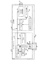
図4は、実例となる圧力トランスミッタ36の簡略化されたブロック図である。この例では、圧力トランスミッタ36は、データバス66を通して共に結合されたセンサモジュール52および電子基板72を含む。センサモジュール電子機器60は、加えられた差圧54を受ける圧力センサ56に結合される。データ接続58は、アナログ・ディジタル変換器62にセンサ56を結合させる。また、センサモジュールメモリ64とともに、任意の温度センサ63が図示されている。電子基板72は、マイクロコンピュータシステム74、電子メモリモジュール76、ディジタル・アナログ信号変換器78、およびディジタル通信ブロック80を含む。ディジタル・アナログ信号変換回路78は、センサ圧力に関する任意のタイプの出力を提供することができ、たとえば差圧に基づいて判定されたプロセス流体の流量を含む。他のタイプの出力は、プロセス圧力、診断出力、温度出力、または他の示唆を含む。
FIG. 4 is a simplified block diagram of an
Frickらの米国特許第6,295,875号に示された手法によれば、圧力トランスミッタ36は、差圧を感知する。しかし、本発明は、そのような構成に限定されない。
According to the approach shown in Frick et al. US Pat. No. 6,295,875,
図4は、ソース14に結合された音響源14と、圧力センサ56に結合された音響センサ18とをさらに図示している。ソース14からの音響信号16は、センサ56内の加圧された流体を通って伝わり、センサ18によって受信される。センサ18の出力は、アナログ・ディジタル変換器62に提供される。マイクロコンピュータシステム74は、センサ18からのディジタル化された信号を受信し、上述の手法を用いて、ライン圧力を判定する。
FIG. 4 further illustrates the
図5は、圧力センサ56を示しているセンサモジュール52の、一つの実施形態の簡略化された断面図である。圧力センサ56は、キャビティ92からプロセス流体を分離する分離ダイヤフラム90を通してプロセス流体に結合する。キャビティ92は、インパルス配管94を通して、圧力センサモジュール56に結合する。実質的に非圧縮性の充填流体は、キャビティ92およびインパルス配管94を満たす。プロセス流体からの圧力は、ダイヤフラム90に対して加えられると、圧力センサ56に伝達される。
FIG. 5 is a simplified cross-sectional view of one embodiment of
圧力センサ56は、2つの圧力センサ半体114および116から形成され、好ましくは脆性の、実質的に非圧縮性の材料105で満たされる。ダイヤフラム106は、センサ56の内部に形成されたキャビティ132、134内部に架けられる。キャビティ132、134の外壁には、電極146、144、148および150が設けられている。一般的には、これらは、一次電極144および148、ならびに二次的な、すなわち二次電極146および150と呼ばれることがある。これらの電極は、可動ダイヤフラム106に対するコンデンサを形成する。さらに、コンデンサは、一次および二次コンデンサと呼ばれることがある。
The
図5に図示されるように、センサ56のさまざまな電極が、電気接続103、104、108および110を通じて、アナログ・ディジタル変換器62に結合される。さらに、可撓性ダイヤフラム106は、接続109を通して、アナログ・ディジタル変換器62に結合される。米国特許第6,295,875号で述べられたように、センサ56に加えられた差圧は、電極144〜150を用いて測定することができる。
As illustrated in FIG. 5, the various electrodes of
図5は、上述の音響センサ18内の音響源14をさらに示している。音響センサ18からアナログ・ディジタル信号変換器62への電気接続170が提供される。音響源14は、独立して動作することができ、またはトランスミッタ内部の回路の制御下で作動することができる。たとえば、図4のセンサモジュール52または電子基板72内部の回路によって、音響源14を制御することができる。
FIG. 5 further shows the
図5に図示されるように、ソース14およびセンサ18の位置取りのために、音響信号16(図5に図示せず)は、センサ56を横断し、センサキャビティ内で運ばれる充填流体を通して伝わる。この充填流体は加圧されるが、それはインパルス配管94および分離ダイヤフラム90を通したプロセス流体への接続のためである。
As illustrated in FIG. 5, due to the positioning of the
図4および5は、可撓性ダイヤフラムを用いた差圧センサを図示しているが、本発明は、任意のタイプの圧力センサを用いて実施することができる。上述のように、本発明はまた、スタンドアローンの圧力センサで実施することもできる。加えて、音響信号は、加圧された流体が供給されるシステムの任意の点に結合することができる。たとえば、図5に図示するように、毛細管94またはキャビティ92に、音響信号を結合することができる。上述のようなライン圧力の判定に加え、音響信号を用いて、高速なプロセスノイズを測定することもでき、これは、たとえば診断で用いることができる。音響信号を、単一の周波数に、変化する周波数に、または複数の周波数にして、測定特性を強化することができる。別の例の構成では、音響信号16は、プロセス自体の中のノイズから直接生成される。そのような構成では、上記で示されたエレメント14は、第二の音響センサを含むことができる。そのような構成では、ノイズ信号のセンサ14および18間の通過時間を用いて、ライン圧力を推測することができる。別の例では、2つのセンサを用いて、2点間のプロセスノイズの分散を測定する。その後、この情報を用いて、ライン圧力を推測することができる。別の例の構成では、図5に図示されるような付加的な音響センサ200が設けられる。音響センサ200は、ソース14と受信器18との間の或る位置、たとえばキャビティ92の内部に挿入される。この付加的なセンサ200を用いて、モジュール内のプロセスノイズの遅延を検出することができる。たとえば、既存の圧力センサは、より低周波数のプロセスノイズを検出する能力がある。付加的なセンサ200を用いて、モジュール内部のプロセスノイズの遅延を検出することができ、センサ電極144または148によって検出された音響信号と比較することができる。
4 and 5 illustrate a differential pressure sensor using a flexible diaphragm, the invention can be implemented using any type of pressure sensor. As mentioned above, the present invention can also be implemented with a stand-alone pressure sensor. In addition, the acoustic signal can be coupled to any point in the system where pressurized fluid is supplied. For example, an acoustic signal can be coupled to the capillary 94 or
好ましい実施形態を参照して本発明を説明してきたが、当業者においては、本発明の本質および範囲から逸脱することなく、形態および細部に変更を加えてもよいことが認識されよう。 Although the present invention has been described with reference to preferred embodiments, workers skilled in the art will recognize that changes may be made in form and detail without departing from the spirit and scope of the invention.
Claims (3)
流体の圧力に結合し、プロセス圧力に関する出力を提供するように構成された圧力センサと、
流体内に音響信号を伝送するように構成され、前記圧力センサの本体に直接的に結合された音響源と、
流体から音響信号を受信するように構成され、前記圧力センサの本体に直接的に結合された音響検出器と、
圧力センサと音響検出器とに結合された測定回路と、を含み、
圧力センサが、可撓性ダイヤフラムを含み、
流体が、分離ダイヤフラムを通してプロセス流体に結合された分離流体を含み、
測定回路は、前記分離流体の圧力と、音響信号の前記分離流体中における伝播速度の変化との間の関係に基づいて、前記分離流体の圧力を判定する、トランスミッタ。 A transmitter configured to measure a process variable of an industrial process,
A pressure sensor coupled to the pressure of the fluid and configured to provide an output related to the process pressure;
An acoustic source configured to transmit an acoustic signal into the fluid and coupled directly to the body of the pressure sensor;
An acoustic detector configured to receive an acoustic signal from a fluid and coupled directly to the body of the pressure sensor;
A measurement circuit coupled to the pressure sensor and the acoustic detector,
The pressure sensor includes a flexible diaphragm;
The fluid includes a separation fluid coupled to the process fluid through a separation diaphragm;
A transmitter, wherein the measurement circuit determines the pressure of the separation fluid based on a relationship between the pressure of the separation fluid and a change in propagation velocity of an acoustic signal in the separation fluid.
Applications Claiming Priority (3)
| Application Number | Priority Date | Filing Date | Title |
|---|---|---|---|
| US11/238,654 US7379792B2 (en) | 2005-09-29 | 2005-09-29 | Pressure transmitter with acoustic pressure sensor |
| US11/238,654 | 2005-09-29 | ||
| PCT/US2006/036404 WO2007040980A1 (en) | 2005-09-29 | 2006-09-19 | Pressure transmitter with acoustic pressure sensor |
Publications (3)
| Publication Number | Publication Date |
|---|---|
| JP2009510483A JP2009510483A (en) | 2009-03-12 |
| JP2009510483A5 JP2009510483A5 (en) | 2009-10-22 |
| JP5743378B2 true JP5743378B2 (en) | 2015-07-01 |
Family
ID=37636085
Family Applications (1)
| Application Number | Title | Priority Date | Filing Date |
|---|---|---|---|
| JP2008538883A Expired - Fee Related JP5743378B2 (en) | 2005-09-29 | 2006-09-19 | Pressure transmitter with acoustic pressure sensor |
Country Status (7)
| Country | Link |
|---|---|
| US (1) | US7379792B2 (en) |
| EP (1) | EP1929264B1 (en) |
| JP (1) | JP5743378B2 (en) |
| CN (1) | CN101273257B (en) |
| CA (1) | CA2621313C (en) |
| RU (1) | RU2421698C2 (en) |
| WO (1) | WO2007040980A1 (en) |
Families Citing this family (8)
| Publication number | Priority date | Publication date | Assignee | Title |
|---|---|---|---|---|
| DE102008043467A1 (en) * | 2008-11-04 | 2010-05-06 | Endress + Hauser Gmbh + Co. Kg | Device for determining and / or monitoring a pressure |
| US8234927B2 (en) * | 2010-06-08 | 2012-08-07 | Rosemount Inc. | Differential pressure sensor with line pressure measurement |
| US9470084B2 (en) * | 2010-08-12 | 2016-10-18 | Rosemount Inc. | Method and apparatus for measuring fluid process variable in a well |
| US8448519B2 (en) * | 2010-10-05 | 2013-05-28 | Rosemount Inc. | Industrial process transmitter with high static pressure isolation diaphragm coupling |
| CN102095466B (en) * | 2010-11-26 | 2012-10-17 | 中国航空工业集团公司北京长城计量测试技术研究所 | Volume measurement method based on sound generating principle of piston |
| US9423315B2 (en) * | 2013-10-15 | 2016-08-23 | Rosemount Aerospace Inc. | Duplex pressure transducers |
| CN104775884B (en) * | 2014-01-09 | 2019-11-08 | 罗伯特·博世有限公司 | Method and apparatus for running internal combustion engine |
| KR102258580B1 (en) * | 2020-04-16 | 2021-06-01 | 한국원자력연구원 | Pressure transmitter |
Family Cites Families (102)
| Publication number | Priority date | Publication date | Assignee | Title |
|---|---|---|---|---|
| US2533339A (en) * | 1946-06-22 | 1950-12-12 | Jabez Burns & Sons Inc | Flammable vapor protection |
| US3012432A (en) * | 1957-09-23 | 1961-12-12 | Richard H Moore | Leak tester |
| GB1023042A (en) * | 1962-05-07 | 1966-03-16 | Wayne Kerr Lab Ltd | Improvements in or relating to pressure responsive apparatus |
| US3232712A (en) * | 1962-08-16 | 1966-02-01 | Continental Lab Inc | Gas detector and analyzer |
| US3374112A (en) * | 1964-03-05 | 1968-03-19 | Yeda Res & Dev | Method and apparatus for controlled deposition of a thin conductive layer |
| US3249833A (en) * | 1964-11-16 | 1966-05-03 | Robert E Vosteen | Capacitor transducer |
| US3557621A (en) * | 1969-07-07 | 1971-01-26 | C G S Scient Corp Inc | Variable capacitance detecting devices |
| GB1354025A (en) * | 1970-05-25 | 1974-06-05 | Medicor Muevek | Capacitive pressure transducer |
| US3924219A (en) * | 1971-12-22 | 1975-12-02 | Minnesota Mining & Mfg | Gas detection device |
| US3808480A (en) * | 1973-04-16 | 1974-04-30 | Bunker Ramo | Capacitive pressure transducer |
| US4008619A (en) | 1975-11-17 | 1977-02-22 | Mks Instruments, Inc. | Vacuum monitoring |
| US4177496A (en) * | 1976-03-12 | 1979-12-04 | Kavlico Corporation | Capacitive pressure transducer |
| US4158217A (en) * | 1976-12-02 | 1979-06-12 | Kaylico Corporation | Capacitive pressure transducer with improved electrode |
| US4120206A (en) * | 1977-01-17 | 1978-10-17 | Rosemount Inc. | Differential pressure sensor capsule with low acceleration sensitivity |
| US4168518A (en) * | 1977-05-10 | 1979-09-18 | Lee Shih Y | Capacitor transducer |
| US4227419A (en) * | 1979-09-04 | 1980-10-14 | Kavlico Corporation | Capacitive pressure transducer |
| US4244226A (en) * | 1979-10-04 | 1981-01-13 | Honeywell Inc. | Distance measuring apparatus and a differential pressure transmitter utilizing the same |
| US4434451A (en) * | 1979-10-29 | 1984-02-28 | Delatorre Leroy C | Pressure sensors |
| US4322775A (en) * | 1979-10-29 | 1982-03-30 | Delatorre Leroy C | Capacitive pressure sensor |
| US4287553A (en) * | 1980-06-06 | 1981-09-01 | The Bendix Corporation | Capacitive pressure transducer |
| US4336567A (en) * | 1980-06-30 | 1982-06-22 | The Bendix Corporation | Differential pressure transducer |
| US4370890A (en) * | 1980-10-06 | 1983-02-01 | Rosemount Inc. | Capacitive pressure transducer with isolated sensing diaphragm |
| US4358814A (en) * | 1980-10-27 | 1982-11-09 | Setra Systems, Inc. | Capacitive pressure sensor |
| US4422335A (en) * | 1981-03-25 | 1983-12-27 | The Bendix Corporation | Pressure transducer |
| US4458537A (en) * | 1981-05-11 | 1984-07-10 | Combustion Engineering, Inc. | High accuracy differential pressure capacitive transducer |
| US4389895A (en) * | 1981-07-27 | 1983-06-28 | Rosemount Inc. | Capacitance pressure sensor |
| US4466290A (en) * | 1981-11-27 | 1984-08-21 | Rosemount Inc. | Apparatus for conveying fluid pressures to a differential pressure transducer |
| US4455874A (en) * | 1981-12-28 | 1984-06-26 | Paroscientific, Inc. | Digital pressure transducer |
| US4422125A (en) * | 1982-05-21 | 1983-12-20 | The Bendix Corporation | Pressure transducer with an invariable reference capacitor |
| DE3238430A1 (en) | 1982-10-16 | 1984-04-19 | Philips Patentverwaltung Gmbh, 2000 Hamburg | DIFFERENTIAL PRESSURE SENSOR |
| US4558184A (en) | 1983-02-24 | 1985-12-10 | At&T Bell Laboratories | Integrated capacitive transducer |
| US4490773A (en) * | 1983-12-19 | 1984-12-25 | United Technologies Corporation | Capacitive pressure transducer |
| US4542436A (en) * | 1984-04-10 | 1985-09-17 | Johnson Service Company | Linearized capacitive pressure transducer |
| US4562742A (en) * | 1984-08-07 | 1986-01-07 | Bell Microcomponents, Inc. | Capacitive pressure transducer |
| US4586108A (en) | 1984-10-12 | 1986-04-29 | Rosemount Inc. | Circuit for capacitive sensor made of brittle material |
| US4578735A (en) | 1984-10-12 | 1986-03-25 | Knecht Thomas A | Pressure sensing cell using brittle diaphragm |
| US4670733A (en) * | 1985-07-01 | 1987-06-02 | Bell Microsensors, Inc. | Differential pressure transducer |
| JPS62187820U (en) * | 1986-05-22 | 1987-11-30 | ||
| US4860232A (en) * | 1987-04-22 | 1989-08-22 | Massachusetts Institute Of Technology | Digital technique for precise measurement of variable capacitance |
| FR2614986B1 (en) | 1987-05-07 | 1989-08-18 | Otic Fischer & Porter | CAPACITIVE CELL STRUCTURE FOR MEASURING DIFFERENTIAL PRESSURES |
| US4785669A (en) * | 1987-05-18 | 1988-11-22 | Mks Instruments, Inc. | Absolute capacitance manometers |
| US4875369A (en) * | 1987-09-08 | 1989-10-24 | Panex Corporation | Pressure sensor system |
| US4945768A (en) * | 1988-05-20 | 1990-08-07 | Parker Electronics, Inc. | Pressure sensor |
| US4878012A (en) * | 1988-06-10 | 1989-10-31 | Rosemount Inc. | Charge balanced feedback transmitter |
| US4977480A (en) * | 1988-09-14 | 1990-12-11 | Fuji Koki Mfg. Co., Ltd. | Variable-capacitance type sensor and variable-capacitance type sensor system using the same |
| US5637302A (en) * | 1988-09-20 | 1997-06-10 | Indena Spa | Extracts of Ginkgo biloba and their methods of preparation |
| US4926674A (en) * | 1988-11-03 | 1990-05-22 | Innovex Inc. | Self-zeroing pressure signal generator |
| US4951174A (en) * | 1988-12-30 | 1990-08-21 | United Technologies Corporation | Capacitive pressure sensor with third encircling plate |
| US5040415A (en) | 1990-06-15 | 1991-08-20 | Rockwell International Corporation | Nonintrusive flow sensing system |
| US5194819A (en) * | 1990-08-10 | 1993-03-16 | Setra Systems, Inc. | Linearized capacitance sensor system |
| US5094109A (en) * | 1990-12-06 | 1992-03-10 | Rosemount Inc. | Pressure transmitter with stress isolation depression |
| US5168419A (en) * | 1991-07-16 | 1992-12-01 | Panex Corporation | Capacitor and pressure transducer |
| US5230250A (en) * | 1991-09-03 | 1993-07-27 | Delatorre Leroy C | Capacitor and pressure transducer |
| JP3182807B2 (en) * | 1991-09-20 | 2001-07-03 | 株式会社日立製作所 | Multifunctional fluid measurement transmission device and fluid volume measurement control system using the same |
| US5233875A (en) * | 1992-05-04 | 1993-08-10 | Kavlico Corporation | Stable capacitive pressure transducer system |
| US5329818A (en) * | 1992-05-28 | 1994-07-19 | Rosemount Inc. | Correction of a pressure indication in a pressure transducer due to variations of an environmental condition |
| US5492016A (en) * | 1992-06-15 | 1996-02-20 | Industrial Sensors, Inc. | Capacitive melt pressure measurement with center-mounted electrode post |
| JPH06102127A (en) * | 1992-09-22 | 1994-04-15 | Yokogawa Electric Corp | Pressure/difference pressure transmitter |
| JPH0712667A (en) * | 1993-06-29 | 1995-01-17 | Hitachi Ltd | Physical quantity sensor and physical quantity sensor system |
| JP3341091B2 (en) * | 1993-06-29 | 2002-11-05 | 耕司 戸田 | Ultrasonic displacement sensor |
| SG41962A1 (en) * | 1993-09-24 | 1997-08-15 | Rosemount Inc | Pressure transmitter isolation diaphragm |
| DE4333753A1 (en) | 1993-10-04 | 1994-05-11 | Bosch Gmbh Robert | Capacitive difference pressure sensor - has carrier supporting counter-electrodes between facing membranes carrying capacitor electrodes |
| US5542300A (en) * | 1994-01-24 | 1996-08-06 | Setra Systems, Inc. | Low cost, center-mounted capacitive pressure sensor |
| US5642301A (en) * | 1994-01-25 | 1997-06-24 | Rosemount Inc. | Transmitter with improved compensation |
| US5415048A (en) * | 1994-06-27 | 1995-05-16 | Texaco Inc. | Acoustic gas-liquid flow meter |
| WO1996017235A1 (en) * | 1994-11-30 | 1996-06-06 | Rosemount Inc. | Pressure transmitter with fill fluid loss detection |
| US6484585B1 (en) * | 1995-02-28 | 2002-11-26 | Rosemount Inc. | Pressure sensor for a pressure transmitter |
| US5637802A (en) | 1995-02-28 | 1997-06-10 | Rosemount Inc. | Capacitive pressure sensor for a pressure transmitted where electric field emanates substantially from back sides of plates |
| US5705978A (en) * | 1995-09-29 | 1998-01-06 | Rosemount Inc. | Process control transmitter |
| US5992240A (en) * | 1995-11-21 | 1999-11-30 | Fuji Electric Co., Ltd. | Pressure detecting apparatus for measuring pressure based on detected capacitance |
| US5757608A (en) * | 1996-01-25 | 1998-05-26 | Alliedsignal Inc. | Compensated pressure transducer |
| US6654697B1 (en) * | 1996-03-28 | 2003-11-25 | Rosemount Inc. | Flow measurement with diagnostics |
| US5668322A (en) * | 1996-06-13 | 1997-09-16 | Rosemount Inc. | Apparatus for coupling a transmitter to process fluid having a sensor extension selectively positionable at a plurality of angles |
| DE19633630A1 (en) | 1996-08-21 | 1998-02-26 | Endress Hauser Gmbh Co | Evaluation unit of a differential pressure sensor |
| US20040015069A1 (en) * | 1996-12-27 | 2004-01-22 | Brown David Lloyd | System for locating inflamed plaque in a vessel |
| US5911162A (en) * | 1997-06-20 | 1999-06-08 | Mks Instruments, Inc. | Capacitive pressure transducer with improved electrode support |
| JPH1151795A (en) * | 1997-08-08 | 1999-02-26 | Saginomiya Seisakusho Inc | Semiconductor pressure sensor and its manufacture |
| WO1999053286A1 (en) | 1998-04-09 | 1999-10-21 | Ploechinger Heinz | Capacitive pressure or force sensor structure and method for producing the same |
| JP3567089B2 (en) | 1998-10-12 | 2004-09-15 | 株式会社日立製作所 | Capacitive pressure sensor |
| US6301973B1 (en) * | 1999-04-30 | 2001-10-16 | The United States Of America As Represented By The Administrator Of The National Aeronautics And Space Administration | Non-intrusive pressure/multipurpose sensor and method |
| US6295875B1 (en) * | 1999-05-14 | 2001-10-02 | Rosemount Inc. | Process pressure measurement devices with improved error compensation |
| DE69936794T2 (en) | 1999-08-20 | 2008-04-30 | Hitachi, Ltd. | SEMICONDUCTOR PRESSURE SENSOR AND DEVICE FOR DETECTING PRINTING |
| US6701274B1 (en) * | 1999-08-27 | 2004-03-02 | Rosemount Inc. | Prediction of error magnitude in a pressure transmitter |
| US6484107B1 (en) * | 1999-09-28 | 2002-11-19 | Rosemount Inc. | Selectable on-off logic modes for a sensor module |
| US6520020B1 (en) * | 2000-01-06 | 2003-02-18 | Rosemount Inc. | Method and apparatus for a direct bonded isolated pressure sensor |
| US6425290B2 (en) | 2000-02-11 | 2002-07-30 | Rosemount Inc. | Oil-less differential pressure sensor |
| US6662662B1 (en) * | 2000-05-04 | 2003-12-16 | Rosemount, Inc. | Pressure transmitter with improved isolator system |
| US6516672B2 (en) * | 2001-05-21 | 2003-02-11 | Rosemount Inc. | Sigma-delta analog to digital converter for capacitive pressure sensor and process transmitter |
| US6828801B1 (en) | 2001-10-26 | 2004-12-07 | Welch Allyn, Inc. | Capacitive sensor |
| US7359803B2 (en) * | 2002-01-23 | 2008-04-15 | Cidra Corporation | Apparatus and method for measuring parameters of a mixture having solid particles suspended in a fluid flowing in a pipe |
| EP1476727B1 (en) * | 2002-01-23 | 2012-03-14 | Cidra Corporate Services, Inc. | Apparatus and method for measuring parameters of a mixture having solid particles suspended in a fluid flowing in a pipe |
| US6675655B2 (en) * | 2002-03-21 | 2004-01-13 | Rosemount Inc. | Pressure transmitter with process coupling |
| US6647794B1 (en) | 2002-05-06 | 2003-11-18 | Rosemount Inc. | Absolute pressure sensor |
| US7400985B2 (en) * | 2002-11-12 | 2008-07-15 | Cidra Corporation | Apparatus having an array of clamp on piezoelectric film sensors for measuring parameters of a process flow within a pipe |
| DE10310114A1 (en) * | 2003-03-06 | 2004-09-16 | Robert Bosch Gmbh | Device and method for hydrostatic pressure determination in a high pressure container by means of ultrasonic transit time measurement |
| EP1631797A2 (en) * | 2003-06-05 | 2006-03-08 | CiDra Corporation | Apparatus for measuring velocity and flow rate of a fluid having a non-negligible axial mach number using an array of sensors |
| CN1853098B (en) * | 2003-07-18 | 2010-12-08 | 罗斯蒙德公司 | Acoustic flowmeter and method for monitoring health degree of fixed equipment in industrial process |
| US7523667B2 (en) * | 2003-12-23 | 2009-04-28 | Rosemount Inc. | Diagnostics of impulse piping in an industrial process |
| US6945115B1 (en) | 2004-03-04 | 2005-09-20 | General Mems Corporation | Micromachined capacitive RF pressure sensor |
| US7577543B2 (en) * | 2005-03-11 | 2009-08-18 | Honeywell International Inc. | Plugged impulse line detection |
| US7401522B2 (en) * | 2005-05-26 | 2008-07-22 | Rosemount Inc. | Pressure sensor using compressible sensor body |
| US7334484B2 (en) * | 2005-05-27 | 2008-02-26 | Rosemount Inc. | Line pressure measurement using differential pressure sensor |
-
2005
- 2005-09-29 US US11/238,654 patent/US7379792B2/en active Active
-
2006
- 2006-09-19 RU RU2008116824/28A patent/RU2421698C2/en not_active IP Right Cessation
- 2006-09-19 WO PCT/US2006/036404 patent/WO2007040980A1/en active Application Filing
- 2006-09-19 JP JP2008538883A patent/JP5743378B2/en not_active Expired - Fee Related
- 2006-09-19 EP EP06814912.9A patent/EP1929264B1/en active Active
- 2006-09-19 CA CA2621313A patent/CA2621313C/en not_active Expired - Fee Related
- 2006-09-19 CN CN2006800356927A patent/CN101273257B/en active Active
Also Published As
| Publication number | Publication date |
|---|---|
| JP2009510483A (en) | 2009-03-12 |
| CN101273257B (en) | 2010-05-19 |
| US7379792B2 (en) | 2008-05-27 |
| EP1929264B1 (en) | 2018-04-04 |
| RU2008116824A (en) | 2009-11-10 |
| CN101273257A (en) | 2008-09-24 |
| WO2007040980A1 (en) | 2007-04-12 |
| CA2621313C (en) | 2014-11-25 |
| US20070073417A1 (en) | 2007-03-29 |
| CA2621313A1 (en) | 2007-04-12 |
| EP1929264A1 (en) | 2008-06-11 |
| RU2421698C2 (en) | 2011-06-20 |
Similar Documents
| Publication | Publication Date | Title |
|---|---|---|
| JP5743378B2 (en) | Pressure transmitter with acoustic pressure sensor | |
| JP5409965B2 (en) | Differential pressure sensor with line pressure measurement | |
| CN100504310C (en) | Diagnostics of impulse piping in an industrial process | |
| JP5923500B2 (en) | Differential pressure transmitter with complementary dual absolute pressure sensor | |
| CA2873030C (en) | Differential pressure type flowmeter having redundant pressure sensors allowing sensor failure and degradation detection | |
| RU2606931C1 (en) | Primary element with sensors for flow meter | |
| CN102243124B (en) | Based on the pressure transducer of resonance frequency | |
| RU2407997C2 (en) | Pressure sensor fault detection | |
| JP5097132B2 (en) | Multiphase overreading correction in process variable transmitters | |
| WO2008021017A2 (en) | Flow measurement diagnostics | |
| EP3158297B1 (en) | System of ultrasonic consumption meters with pressure sensors | |
| WO2004053430A2 (en) | Sensor arrangements and methods of determining a characteristic of a sample fluid using such sensor arrangements |
Legal Events
| Date | Code | Title | Description |
|---|---|---|---|
| A521 | Written amendment |
Free format text: JAPANESE INTERMEDIATE CODE: A523 Effective date: 20090825 |
|
| A621 | Written request for application examination |
Free format text: JAPANESE INTERMEDIATE CODE: A621 Effective date: 20090825 |
|
| A977 | Report on retrieval |
Free format text: JAPANESE INTERMEDIATE CODE: A971007 Effective date: 20111226 |
|
| A131 | Notification of reasons for refusal |
Free format text: JAPANESE INTERMEDIATE CODE: A131 Effective date: 20120110 |
|
| A521 | Written amendment |
Free format text: JAPANESE INTERMEDIATE CODE: A523 Effective date: 20120409 |
|
| A131 | Notification of reasons for refusal |
Free format text: JAPANESE INTERMEDIATE CODE: A131 Effective date: 20121023 |
|
| A601 | Written request for extension of time |
Free format text: JAPANESE INTERMEDIATE CODE: A601 Effective date: 20130122 |
|
| A602 | Written permission of extension of time |
Free format text: JAPANESE INTERMEDIATE CODE: A602 Effective date: 20130129 |
|
| A521 | Written amendment |
Free format text: JAPANESE INTERMEDIATE CODE: A523 Effective date: 20130225 |
|
| A02 | Decision of refusal |
Free format text: JAPANESE INTERMEDIATE CODE: A02 Effective date: 20131017 |
|
| A521 | Written amendment |
Free format text: JAPANESE INTERMEDIATE CODE: A523 Effective date: 20140217 |
|
| A911 | Transfer to examiner for re-examination before appeal (zenchi) |
Free format text: JAPANESE INTERMEDIATE CODE: A911 Effective date: 20140320 |
|
| A912 | Re-examination (zenchi) completed and case transferred to appeal board |
Free format text: JAPANESE INTERMEDIATE CODE: A912 Effective date: 20140530 |
|
| RD04 | Notification of resignation of power of attorney |
Free format text: JAPANESE INTERMEDIATE CODE: A7424 Effective date: 20140726 |
|
| RD04 | Notification of resignation of power of attorney |
Free format text: JAPANESE INTERMEDIATE CODE: A7424 Effective date: 20150304 |
|
| A521 | Written amendment |
Free format text: JAPANESE INTERMEDIATE CODE: A523 Effective date: 20150313 |
|
| A61 | First payment of annual fees (during grant procedure) |
Free format text: JAPANESE INTERMEDIATE CODE: A61 Effective date: 20150428 |
|
| R150 | Certificate of patent or registration of utility model |
Ref document number: 5743378 Country of ref document: JP Free format text: JAPANESE INTERMEDIATE CODE: R150 |
|
| R250 | Receipt of annual fees |
Free format text: JAPANESE INTERMEDIATE CODE: R250 |
|
| R250 | Receipt of annual fees |
Free format text: JAPANESE INTERMEDIATE CODE: R250 |
|
| LAPS | Cancellation because of no payment of annual fees |