JP5739145B2 - Tire tread wear indicator and forming apparatus for forming tread wear indicator - Google Patents
Tire tread wear indicator and forming apparatus for forming tread wear indicator Download PDFInfo
- Publication number
- JP5739145B2 JP5739145B2 JP2010268312A JP2010268312A JP5739145B2 JP 5739145 B2 JP5739145 B2 JP 5739145B2 JP 2010268312 A JP2010268312 A JP 2010268312A JP 2010268312 A JP2010268312 A JP 2010268312A JP 5739145 B2 JP5739145 B2 JP 5739145B2
- Authority
- JP
- Japan
- Prior art keywords
- depth
- tread
- range
- wear indicator
- cross
- Prior art date
- Legal status (The legal status is an assumption and is not a legal conclusion. Google has not performed a legal analysis and makes no representation as to the accuracy of the status listed.)
- Active
Links
- 241000533950 Leucojum Species 0.000 claims description 9
- 239000007787 solid Substances 0.000 claims 5
- 238000000465 moulding Methods 0.000 description 15
- 238000007493 shaping process Methods 0.000 description 8
- NJPPVKZQTLUDBO-UHFFFAOYSA-N novaluron Chemical compound C1=C(Cl)C(OC(F)(F)C(OC(F)(F)F)F)=CC=C1NC(=O)NC(=O)C1=C(F)C=CC=C1F NJPPVKZQTLUDBO-UHFFFAOYSA-N 0.000 description 4
- 230000015572 biosynthetic process Effects 0.000 description 2
- 229910000831 Steel Inorganic materials 0.000 description 1
- 229910052782 aluminium Inorganic materials 0.000 description 1
- XAGFODPZIPBFFR-UHFFFAOYSA-N aluminium Chemical compound [Al] XAGFODPZIPBFFR-UHFFFAOYSA-N 0.000 description 1
- 238000004040 coloring Methods 0.000 description 1
- 238000010586 diagram Methods 0.000 description 1
- 230000008034 disappearance Effects 0.000 description 1
- 239000000835 fiber Substances 0.000 description 1
- 229910052751 metal Inorganic materials 0.000 description 1
- 239000002184 metal Substances 0.000 description 1
- 238000012986 modification Methods 0.000 description 1
- 230000004048 modification Effects 0.000 description 1
- 239000012778 molding material Substances 0.000 description 1
- 239000010959 steel Substances 0.000 description 1
- XLYOFNOQVPJJNP-UHFFFAOYSA-N water Substances O XLYOFNOQVPJJNP-UHFFFAOYSA-N 0.000 description 1
Images


Classifications
-
- B—PERFORMING OPERATIONS; TRANSPORTING
- B60—VEHICLES IN GENERAL
- B60C—VEHICLE TYRES; TYRE INFLATION; TYRE CHANGING; CONNECTING VALVES TO INFLATABLE ELASTIC BODIES IN GENERAL; DEVICES OR ARRANGEMENTS RELATED TO TYRES
- B60C11/00—Tyre tread bands; Tread patterns; Anti-skid inserts
- B60C11/24—Wear-indicating arrangements
-
- B—PERFORMING OPERATIONS; TRANSPORTING
- B29—WORKING OF PLASTICS; WORKING OF SUBSTANCES IN A PLASTIC STATE IN GENERAL
- B29D—PRODUCING PARTICULAR ARTICLES FROM PLASTICS OR FROM SUBSTANCES IN A PLASTIC STATE
- B29D30/00—Producing pneumatic or solid tyres or parts thereof
- B29D30/06—Pneumatic tyres or parts thereof (e.g. produced by casting, moulding, compression moulding, injection moulding, centrifugal casting)
- B29D30/0601—Vulcanising tyres; Vulcanising presses for tyres
- B29D30/0606—Vulcanising moulds not integral with vulcanising presses
- B29D2030/0607—Constructional features of the moulds
- B29D2030/0612—Means for forming recesses or protrusions in the tyres, e.g. grooves or ribs, to create the tread or sidewalls patterns
-
- B—PERFORMING OPERATIONS; TRANSPORTING
- B60—VEHICLES IN GENERAL
- B60C—VEHICLE TYRES; TYRE INFLATION; TYRE CHANGING; CONNECTING VALVES TO INFLATABLE ELASTIC BODIES IN GENERAL; DEVICES OR ARRANGEMENTS RELATED TO TYRES
- B60C11/00—Tyre tread bands; Tread patterns; Anti-skid inserts
- B60C11/03—Tread patterns
- B60C11/12—Tread patterns characterised by the use of narrow slits or incisions, e.g. sipes
- B60C11/1236—Tread patterns characterised by the use of narrow slits or incisions, e.g. sipes with special arrangements in the tread pattern
- B60C2011/1254—Tread patterns characterised by the use of narrow slits or incisions, e.g. sipes with special arrangements in the tread pattern with closed sipe, i.e. not extending to a groove
-
- Y—GENERAL TAGGING OF NEW TECHNOLOGICAL DEVELOPMENTS; GENERAL TAGGING OF CROSS-SECTIONAL TECHNOLOGIES SPANNING OVER SEVERAL SECTIONS OF THE IPC; TECHNICAL SUBJECTS COVERED BY FORMER USPC CROSS-REFERENCE ART COLLECTIONS [XRACs] AND DIGESTS
- Y10—TECHNICAL SUBJECTS COVERED BY FORMER USPC
- Y10T—TECHNICAL SUBJECTS COVERED BY FORMER US CLASSIFICATION
- Y10T152/00—Resilient tires and wheels
- Y10T152/10—Tires, resilient
- Y10T152/10027—Tires, resilient with wear indicating feature
Description
本発明は、タイヤのトレッド用の摩耗インジケータと、その摩耗インジケータを形成する成形装置とに関する。 The present invention relates to a wear indicator for a tire tread and a molding apparatus for forming the wear indicator.
トレッド摩耗インジケータの使用は新しいことではなく、多くの国では、その使用が法律によって義務付けられている。そのようなさまざまなインジケータが公知である。そのような種類のインジケータとして、摩耗を視覚的に表示するために、トレッドの下方で、着色ゴムや着色繊維などの着色手段を使用したものがある。他の種類では、図9に示すように、トレッド溝に設けられたタイバー型部材が使用されている。トレッド溝のタイバーは、それが水はけ(water evacuation)を妨害する場合に問題となる可能性がある。法律で義務付けられている場合、トレッド摩耗インジケータの上面は、その摩耗インジケータが配置される溝の底部から1.6mmの高さに配置する必要がある。溝の底部から4mmの高さに配置される冬季用トレッド摩耗インジケータの追加要件を課している国もある。 The use of tread wear indicators is not new, and in many countries it is required by law. Various such indicators are known. One such type of indicator uses a colored means such as colored rubber or colored fiber below the tread to visually indicate wear. In another type, as shown in FIG. 9, a tie bar type member provided in the tread groove is used. Tread groove tie bars can be problematic if they interfere with water evacuation. Where required by law, the upper surface of the tread wear indicator should be placed 1.6 mm above the bottom of the groove in which the wear indicator is placed. Some countries impose additional requirements for winter tread wear indicators located 4 mm above the bottom of the groove.
上述した種類の着色インジケータに関する現実的な問題は、摩耗インジケータがトレッドの残りの部分と同じ色であるため、作業員にとって、タイヤが摩耗するまで、摩耗のレベルを判定するのが困難であるということである。 A practical problem with the type of coloring indicator described above is that it is difficult for the operator to determine the level of wear until the tire is worn because the wear indicator is the same color as the rest of the tread. That is.
特許文献1には、一連の、あるいは密接して配置された所定の一群の関連マークにおいて、タイヤが摩耗するにつれてそのマークが消滅する、タイヤトレッド用の摩耗インジケータが開示されている。これにより消費者に連続的な情報が与えられる一方で、摩耗が規定量に達した後でのみ出現する複数の異なるマークを形成する必要があるため、タイヤ形成の複雑さが増すことになる。 Patent Document 1 discloses a wear indicator for a tire tread in which a series of or closely arranged predetermined groups of related marks disappear as the tire wears. While this provides continuous information to the consumer, it increases the complexity of tire formation because it is necessary to form a plurality of different marks that only appear after wear reaches a specified amount.
本発明は、少なくとも1つのトレッド摩耗インジケータを有するタイヤに関する。同様に、このトレッド摩耗インジケータを形成するために用いられる成形ブレードも開示される。ブレードは、ブレードの規定された深さにわたって一定である第1の断面形状を有する第1の部分を備えている。ブレードはさらに、ブレードの第2の規定された深さにわたって一定である第2の断面形状を有する第2の部分を任意に備えていてよい。ブレードはさらに、ブレードの第3の規定された深さにわたって第3の断面形状を有する第3の部分を任意に備えていてよい。 The present invention relates to a tire having at least one tread wear indicator. Similarly, a forming blade used to form the tread wear indicator is also disclosed. The blade includes a first portion having a first cross-sectional shape that is constant over a defined depth of the blade. The blade may further optionally include a second portion having a second cross-sectional shape that is constant over a second defined depth of the blade. The blade may further optionally include a third portion having a third cross-sectional shape over a third defined depth of the blade.
車両用タイヤのタイヤトレッドであって、トレッドの底部から突出し、規定されたトレッド深さを有する少なくとも1つのトレッド部材を有するタイヤトレッドが開示される。少なくとも1つのトレッド部材は、トレッド摩耗インジケータを有している。摩耗インジケータは、タイヤに形成された穴であり、それは規定されたトレッド深さdにわたって一定の断面形状を有している。したがって、例えば、摩耗インジケータは、規定された深さが摩耗した後で消滅する雪片状の穴であってよい。摩耗インジケータは、第1の断面形状が摩耗した後でその形状が現れる、トレッドに設けられた第2の穴をさらに含んでいてよい。第2の形状は、第1の形状と異なる断面形状を有し、規定された深さにわたって一定の断面形状を有している。摩耗インジケータはさらに、第1の穴や第2の穴とは断面形状が異なる第3の穴を任意に含んでいてよい。 Disclosed is a tire tread for a vehicle tire having at least one tread member protruding from the bottom of the tread and having a defined tread depth. At least one tread member has a tread wear indicator. A wear indicator is a hole formed in the tire, which has a constant cross-sectional shape over a defined tread depth d. Thus, for example, the wear indicator may be a snowflake-like hole that disappears after a defined depth has worn. The wear indicator may further include a second hole in the tread that appears after the first cross-sectional shape is worn. The second shape has a cross-sectional shape different from the first shape, and has a constant cross-sectional shape over a specified depth. The wear indicator may optionally further include a third hole having a different cross-sectional shape from the first hole or the second hole.
また、本発明の一態様では、少なくとも1つのトレッド部材が、第1の深さにわたって一定である外側の第1の断面形状を有する第1の穴を有していてもよい。 In one embodiment of the present invention, at least one tread member may have a first hole having an outer first cross-sectional shape that is constant over a first depth.
(定義)
以下の定義を本発明に適用することができる。
(Definition)
The following definitions can be applied to the present invention.
「内側」は、タイヤの内側の方向を意味し、「外側」はタイヤの外側の方向を意味する。 “Inside” means the direction inside the tire, and “outside” means the direction outside the tire.
「外側」は、タイヤの外側の方向を意味する。 “Outside” means the direction of the outside of the tire.
「半径方向の」および「半径方向に」は、タイヤの回転軸に向かって放射状に延びる方向、あるいは回転軸から離れるように放射状に延びる方向を意味するのに用いられる。 “Radial” and “radially” are used to mean a direction that extends radially toward the axis of rotation of the tire or a direction that extends radially away from the axis of rotation.
「トレッド」は、タイヤケーシングに結合されたときに、タイヤが標準荷重の下で通常の膨張時に道路に接触する部分を含む、成形ゴム構成部材を意味する。トレッドは、タイヤのトレッド面から最も深い溝の底部まで従来の方法で測定された深さを有している。 “Tread” means a molded rubber component that, when joined to a tire casing, includes a portion where the tire contacts the road under normal load during normal inflation. The tread has a depth measured in a conventional manner from the tread surface of the tire to the bottom of the deepest groove.
本発明について、一例として、添付の図面を参照して説明する。 The present invention will now be described by way of example with reference to the accompanying drawings.
以下の文言は、本発明を実施する、現在考えられる最良の形態について述べたものである。この説明は、本発明の一般原理を例示するためになされており、制限的に解釈すべきものではない。本発明の範囲は、添付の特許請求の範囲を参照することによって最良に決定される。図面に示す参照符号は、本明細書で引用される参照符号と同じものである。本出願の目的のために、図に示す様々な実施形態では、それぞれ同様の構成部材には同じ参照符号を使用している。基本的に、各構造に位置または数量の異なる同じ構成部材を使用することによって、本発明の概念を実施することができる代替構成がもたらされる。 The following language describes the best presently contemplated mode of carrying out the invention. This description is made for the purpose of illustrating the general principles of the invention and should not be construed as limiting. The scope of the invention is best determined by reference to the appended claims. Reference numerals shown in the drawings are the same as those referred to in the present specification. For purposes of this application, the various embodiments shown in the figures use the same reference numerals for similar components. Essentially, the use of the same components in different positions or quantities for each structure provides an alternative configuration that can implement the concepts of the present invention.
図1は、タイヤトレッドの一部を示している。トレッドは、周方向溝12と横方向溝14とによって規定された複数のブロック10を有していてよい。タイヤトレッドの左側は、摩耗していない状態、すなわち新品の状態が示されており、雪片の形をした穴、すなわちトレッド摩耗インジケータ16が図示されている。タイヤの右側は、4mmをわずかに超えるまで磨耗している様子が示されている。トレッドの厳密な構成は、本発明にとっては無関係であり、任意のトレッド構成が使用可能である。トレッドには1つまたは複数の磨耗インジケータ20が配置されている。摩耗インジケータ20は、任意の所望の場所、例えば、トレッドブロック、リブ、あるいは外側トレッド面上のどこか別の場所などに配置されていてよい。磨耗インジケータが溝の内部、すなわち通路内に配置されることはない。
FIG. 1 shows a part of a tire tread. The tread may have a plurality of
磨耗していない場合、摩耗インジケータ20は、第1の形状を有する、トレッド面に設けられた穴または切り欠きによって表される。図2に示すように、切り欠き構成の外周は雪片16のような形をしているが、任意の他の所望の形状であってよい。雪片の形をした穴16は、規定されたトレッド深さが摩耗するまでタイヤの外面上に現れている。したがって、例えば、雪片状の穴が4mmの深さであるとすると、雪片は、トレッドが4mm削り取られると消滅することになる。第1の形状が消滅することによって、消費者は、タイヤが所定のレベルまで摩耗したという警告を受ける。このことを消費者に容易に伝える構成としては、任意の種類の構成が可能である。切り欠きの深さは、タイヤ設計者によって、異なる政府規格に適用できるように選択することができる。
When not worn, the
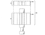
図4から図6には、本発明の第1の成形装置30が示されている。成形装置は、内部ピン34と、成形セグメントのネジまたは他の締結部材を受け入れる内部穴36と、を備えた台座32を有している。台座32はさらに、ブレード38を有している。ブレードは、台座32の穴に受け入れられるとともに、ピン34を用いて台座32に固定される雄部35を有している。ブレードは、この例では雪片として形成されているが、他のデザインも本発明には有効である。ブレードの深さは、必要に応じてサイズが設定されている。成形装置30は、例えば、鋼、アルミニウム、あるいはプレス加工金属のような、従来の成形材料から形成されている。
4 to 6 show the
図3は、セグメント40に挿入された成形装置32を示している。ブレード38の深さ全体が型の中まで延びていることに留意することが重要である。成形装置32は、穴36に固定された締結部材41を用いてトレッドセグメントの穴43に固定されている。
FIG. 3 shows the
図10から図12には、成形ブレード52の第2の実施形態が示されている。ブレード52は、この場合は太陽を模した印(sun indicia)20のような形である第1の形状を有する外側部分56を有している。ブレード52は、この場合は雪片を模した印(snowflake indicia)16である第2の形状で形成された内側部分58を有している。したがって、タイヤに成形されると、消費者はまず、ブレード58の深さに相当する深さXにわたって、図12のような形状の雪片状の穴16を見ることになり、その後、ブレード56の深さに相当する深さYにわたって、太陽印20の形状の第2の記号56を見ることになる。第1の穴と第2の穴とを揃えることが好ましい。
10 to 12 show a second embodiment of the forming
図7、および図13から図16は、本発明の第3の実施形態を示している。ブレード62は、太陽印64の第1の形状を有する外側部分と、雪片印66の第2の形状を有する内側部分とを有している。任意の第3の部分68は、第3の記号を有し、この場合は立入禁止記号(斜線付きの円)である。図16(a)から図16(c)に示すように、消費者はまず、指定された深さにわたって、トレッドの外面上に雪片印66を見ることになり(図16(a))、その後、指定された第2の深さにわたって、第1の太陽印64を見ることになり(図16(b))、そして最後に、警告印68を見ることになる(図16(c))。警告印の穴は、第1の警告深さ(例えば1.8mm)から滑り止め深さまでタイヤトレッドの面上に残ることになる。
7 and FIGS. 13 to 16 show a third embodiment of the present invention. The
図17は、雪片の形をしたトレッド摩耗インジケータ66を備えた状態のトレッドの断面図を示している。雪片状のインジケータは、新品のトレッド上で確認することができ、4mmの深さを有している。トレッドが4mmの深さまで摩耗した後、トレッド深さが1.6mmまでは、太陽を模したトレッド摩耗インジケータ64が表示されることになる。そして、1.6mmから溝深さに到達するまでは、警告印が表示されることになる。
FIG. 17 shows a cross-sectional view of the tread with a
本明細書に記載された本発明の説明を考慮すると、本発明の変形例が可能である。主題発明を例示する目的で、特定の代表的な実施形態および詳細を示しているが、当業者には、主題発明の範囲から逸脱することなく様々な変更および修正を行うことができることが明らかであろう。したがって、前述の特定の実施形態において、添付の特許請求の範囲によって規定される本発明の対象となる全範囲内で行う変更が可能であることを理解されたい。 In light of the description of the invention described herein, variations of the invention are possible. While specific representative embodiments and details are shown for purposes of illustrating the subject invention, it will be apparent to those skilled in the art that various changes and modifications can be made without departing from the scope of the subject invention. I will. It is therefore to be understood that changes may be made in the particular embodiments described above that are within the full scope of the invention as defined by the appended claims.
10 ブロック
12 周方向溝
14 横方向溝
16,20 摩耗インジケータ
30 成形装置
32 台座
34 内部ピン
35 雄部
36 内部穴
38 ブレード
40 セグメント
41 締結部材
43 穴
52,62 ブレード
56,64 外側部分
58,66 内側部分
68 第3の部分
10
Claims (8)
前記第1の断面形状が雪片を模した記号であり、
前記第1の穴または切り欠きが、第2の深さにわたって一定であって太陽を模した記号である第2の断面形状と、第3の深さにわたって一定であって警告記号または立入禁止記号である第3の断面形状とを有することを特徴とするタイヤトレッド。 A tire tread having at least one tread member (10) or block protruding from the bottom or non-slip surface of the tire tread and having a defined tread depth, the at least one tread member (10) or The block has a first hole or notch (16) as a wear indicator, the first hole or notch (16) having a first depth less than the tread depth or anti-slip depth. In a tire tread having an outer first cross-sectional shape that is constant over the length,
Than symbol der that the first cross-sectional shape resembling a snowflake,
A second cross-sectional shape in which the first hole or notch is constant over the second depth and mimics the sun; and a warning symbol or off-limit symbol that is constant over the third depth A tire tread characterized by having a third cross-sectional shape .
前記成形ブレード(38,52,62)が、第2の規定された深さを有する第2の中実部分であって、前記第2の規定された深さにわたって一定であるとともに太陽を模した記号である断面形状を有する第2の中実部分と、第3の規定された深さにわたって一定であるとともに警告記号または立入禁止記号である断面形状を有する第3の中実部分と、を有する成形装置。 A forming apparatus for forming a tread wear indicator on a tread, the forming apparatus (30) having a forming blade (38, 52, 62) with a first solid portion having a defined depth. the first solid portion of, have a cross-sectional shape is a symbol resembling a snowflake with a constant over the prescribed depth,
The forming blade (38, 52, 62) is a second solid part having a second defined depth, which is constant over the second defined depth and imitates the sun A second solid portion having a cross-sectional shape that is a symbol and a third solid portion having a cross-sectional shape that is constant over a third defined depth and that is a warning symbol or an off-limit symbol. Forming equipment.
Applications Claiming Priority (2)
| Application Number | Priority Date | Filing Date | Title |
|---|---|---|---|
| US12/629,364 US20110126949A1 (en) | 2009-12-02 | 2009-12-02 | Tire tread wear indicator and molding device for forming a tread wear indicator |
| US12/629,364 | 2009-12-02 |
Publications (3)
| Publication Number | Publication Date |
|---|---|
| JP2011116362A JP2011116362A (en) | 2011-06-16 |
| JP2011116362A5 JP2011116362A5 (en) | 2013-12-26 |
| JP5739145B2 true JP5739145B2 (en) | 2015-06-24 |
Family
ID=43587461
Family Applications (1)
| Application Number | Title | Priority Date | Filing Date |
|---|---|---|---|
| JP2010268312A Active JP5739145B2 (en) | 2009-12-02 | 2010-12-01 | Tire tread wear indicator and forming apparatus for forming tread wear indicator |
Country Status (5)
| Country | Link |
|---|---|
| US (1) | US20110126949A1 (en) |
| EP (1) | EP2329967B2 (en) |
| JP (1) | JP5739145B2 (en) |
| CN (1) | CN102085777B (en) |
| BR (1) | BRPI1004992A2 (en) |
Families Citing this family (19)
| Publication number | Priority date | Publication date | Assignee | Title |
|---|---|---|---|---|
| JP4605297B1 (en) * | 2009-07-01 | 2011-01-05 | 横浜ゴム株式会社 | Pneumatic tire |
| US8403012B2 (en) | 2010-11-23 | 2013-03-26 | The Goodyear Tire & Rubber Company, Inc. | Tread wear indicator |
| DE102011054662A1 (en) * | 2011-10-20 | 2013-04-25 | Continental Reifen Deutschland Gmbh | Pneumatic vehicle tire with abrasion indicator |
| US8857252B2 (en) * | 2012-06-13 | 2014-10-14 | Continental Reifen Deutschland Gmbh | Optimal tire performance indicator |
| WO2014105502A1 (en) * | 2012-12-26 | 2014-07-03 | Bridgestone Americas Tire Operations, Llc | Tire with substantially helicoid-shaped sipe |
| US9855713B2 (en) * | 2013-11-22 | 2018-01-02 | Andrew Cassidy | Advanced reflective tire marking system for use as a warning indication to highlight the width of large vehicles |
| CN104742663A (en) * | 2013-12-25 | 2015-07-01 | 中橡集团曙光橡胶工业研究设计院 | Tire with abrasion pits |
| USD758297S1 (en) * | 2014-03-18 | 2016-06-07 | Bridgestone Americas Tire Operations, Llc | Tire tread performance indicator |
| USD825447S1 (en) * | 2017-01-24 | 2018-08-14 | The Goodyear Tire & Rubber Company | Tire tread wear indicator |
| USD823784S1 (en) * | 2017-01-24 | 2018-07-24 | The Goodyear Tire & Rubber Company | Tire tread wear indicator |
| US10252580B2 (en) | 2017-01-24 | 2019-04-09 | The Goodyear Tire & Rubber Company | Tread wear indicator |
| DE102018221192A1 (en) * | 2018-12-07 | 2020-06-10 | Continental Reifen Deutschland Gmbh | Tread pattern of a vehicle tire |
| USD886728S1 (en) * | 2018-12-20 | 2020-06-09 | The Goodyear Tire & Rubber Company | Tire tread wear indicator |
| USD886042S1 (en) * | 2018-12-20 | 2020-06-02 | The Goodyear Tire & Rubber Company | Tire tread wear indicator |
| EP3983210A1 (en) * | 2019-06-13 | 2022-04-20 | Pirelli Tyre S.p.A. | Mould and process for vulcanising tyres for vehicle wheels |
| CL2020000326S1 (en) * | 2019-08-08 | 2020-10-02 | Borrachas Vipal S A | Tire wear indicator. |
| CN112109501A (en) * | 2020-09-30 | 2020-12-22 | 山东丰源轮胎制造股份有限公司 | Tire with recognizable pattern depth |
| US11413907B2 (en) | 2020-10-16 | 2022-08-16 | The Goodyear Tire & Rubber Company | Tire with shallow groove-based tread wear indicator |
| DE102022203296A1 (en) * | 2022-04-01 | 2023-10-05 | Continental Reifen Deutschland Gmbh | Pneumatic vehicle tires |
Family Cites Families (7)
| Publication number | Priority date | Publication date | Assignee | Title |
|---|---|---|---|---|
| SU408833A1 (en) * | 1971-07-19 | 1973-11-30 | PNEUMATIC TIRE PROTECTOR | |
| JPS60128005A (en) * | 1983-12-14 | 1985-07-08 | Sumitomo Rubber Ind Ltd | Tyre and its shaping mold |
| FI112340B (en) * | 1999-06-29 | 2003-11-28 | Nokian Renkaat Oyj | Vehicle tire tread with means for indicating at any instant the depth of the tread grooves |
| US20060037683A1 (en) * | 2004-08-23 | 2006-02-23 | Andre Cuny | Tire tread wear indicator and molding device for forming a tread wear indicator |
| CN2759814Y (en) * | 2004-11-26 | 2006-02-22 | 诺基安轮胎有限公司 | Wear indicator used for vehicle tire |
| FR2883508B1 (en) * | 2005-03-25 | 2007-05-18 | Michelin Soc Tech | WEAR INDICATOR FOR PNEUMATIC |
| US8695655B2 (en) * | 2007-10-15 | 2014-04-15 | The Goodyear Tire & Rubber Company | Tire tread with tread wear indicator |
-
2009
- 2009-12-02 US US12/629,364 patent/US20110126949A1/en not_active Abandoned
-
2010
- 2010-11-23 BR BRPI1004992-4A patent/BRPI1004992A2/en not_active IP Right Cessation
- 2010-11-30 EP EP10193082.4A patent/EP2329967B2/en active Active
- 2010-12-01 JP JP2010268312A patent/JP5739145B2/en active Active
- 2010-12-02 CN CN201010570206.XA patent/CN102085777B/en active Active
Also Published As
| Publication number | Publication date |
|---|---|
| CN102085777A (en) | 2011-06-08 |
| JP2011116362A (en) | 2011-06-16 |
| BRPI1004992A2 (en) | 2013-03-12 |
| CN102085777B (en) | 2015-07-29 |
| US20110126949A1 (en) | 2011-06-02 |
| EP2329967B2 (en) | 2017-03-01 |
| EP2329967B1 (en) | 2013-07-17 |
| EP2329967A1 (en) | 2011-06-08 |
Similar Documents
| Publication | Publication Date | Title |
|---|---|---|
| JP5739145B2 (en) | Tire tread wear indicator and forming apparatus for forming tread wear indicator | |
| KR101148359B1 (en) | Tire tread wear indicator and molding device for forming a tread wear indicator | |
| US8162014B2 (en) | Motor-vehicle tyre provided with a tread pattern wear indicator | |
| US7011126B2 (en) | Progressive tire tread wear indicator | |
| US8403012B2 (en) | Tread wear indicator | |
| US20180326795A1 (en) | Tread wear indicator | |
| US11926178B2 (en) | Tire comprising a textured tread | |
| JP2011116362A5 (en) | ||
| JP2016501151A (en) | Wear indicators for civil engineering tires | |
| EP3225428B1 (en) | A mould for making a wear indicator into a pneumatic tyre and a pneumatic tyre comprising a wear indicator | |
| JP2017536535A (en) | Tire wear monitoring device | |
| GB2376002A (en) | Tyre wear indicator | |
| KR200419721Y1 (en) | Wear indicator for vehicle tires | |
| JP2006051844A (en) | Pneumatic tire | |
| KR101966734B1 (en) | Pneumatic tire with performance indicator member | |
| JP6472018B2 (en) | Pneumatic tire | |
| KR200381904Y1 (en) | Vehicle tire indicating the measure of tread wear | |
| JP2008302716A (en) | Pneumatic tire for ice road |
Legal Events
| Date | Code | Title | Description |
|---|---|---|---|
| A521 | Request for written amendment filed |
Free format text: JAPANESE INTERMEDIATE CODE: A523 Effective date: 20131113 |
|
| A621 | Written request for application examination |
Free format text: JAPANESE INTERMEDIATE CODE: A621 Effective date: 20131113 |
|
| RD04 | Notification of resignation of power of attorney |
Free format text: JAPANESE INTERMEDIATE CODE: A7424 Effective date: 20140411 |
|
| A977 | Report on retrieval |
Free format text: JAPANESE INTERMEDIATE CODE: A971007 Effective date: 20140815 |
|
| A131 | Notification of reasons for refusal |
Free format text: JAPANESE INTERMEDIATE CODE: A131 Effective date: 20140909 |
|
| A521 | Request for written amendment filed |
Free format text: JAPANESE INTERMEDIATE CODE: A523 Effective date: 20141209 |
|
| TRDD | Decision of grant or rejection written | ||
| A01 | Written decision to grant a patent or to grant a registration (utility model) |
Free format text: JAPANESE INTERMEDIATE CODE: A01 Effective date: 20150414 |
|
| A61 | First payment of annual fees (during grant procedure) |
Free format text: JAPANESE INTERMEDIATE CODE: A61 Effective date: 20150423 |
|
| R150 | Certificate of patent or registration of utility model |
Ref document number: 5739145 Country of ref document: JP Free format text: JAPANESE INTERMEDIATE CODE: R150 |
|
| R250 | Receipt of annual fees |
Free format text: JAPANESE INTERMEDIATE CODE: R250 |
|
| R250 | Receipt of annual fees |
Free format text: JAPANESE INTERMEDIATE CODE: R250 |
|
| R250 | Receipt of annual fees |
Free format text: JAPANESE INTERMEDIATE CODE: R250 |
|
| R250 | Receipt of annual fees |
Free format text: JAPANESE INTERMEDIATE CODE: R250 |
|
| R250 | Receipt of annual fees |
Free format text: JAPANESE INTERMEDIATE CODE: R250 |
|
| R250 | Receipt of annual fees |
Free format text: JAPANESE INTERMEDIATE CODE: R250 |