JP5738119B2 - Electrical connector - Google Patents
Electrical connector Download PDFInfo
- Publication number
- JP5738119B2 JP5738119B2 JP2011175981A JP2011175981A JP5738119B2 JP 5738119 B2 JP5738119 B2 JP 5738119B2 JP 2011175981 A JP2011175981 A JP 2011175981A JP 2011175981 A JP2011175981 A JP 2011175981A JP 5738119 B2 JP5738119 B2 JP 5738119B2
- Authority
- JP
- Japan
- Prior art keywords
- contact
- insulator
- electrical connector
- shell
- mold
- Prior art date
- Legal status (The legal status is an assumption and is not a legal conclusion. Google has not performed a legal analysis and makes no representation as to the accuracy of the status listed.)
- Expired - Fee Related
Links
Images


Description
本発明は、電気コネクタ及びその製造方法に関し、特に、防水が必要な環境で使用するのに適した電気コネクタ及びその製造方法に関する。 The present invention relates to an electrical connector and a manufacturing method thereof, and more particularly to an electrical connector suitable for use in an environment where waterproofing is required and a manufacturing method thereof.
携帯電話、パソコン等の電子機器は一般的に水に弱く、防水対策を施すことが望まれる。従来の電子機器では、例えば、外部連絡可能な開口部を、シリコンゴムの蓋で閉じる等といった方法で防水対策がなされていた。 Electronic devices such as mobile phones and personal computers are generally vulnerable to water, and it is desired to take waterproof measures. In conventional electronic devices, for example, waterproofing measures have been taken by, for example, closing an externally accessible opening with a silicon rubber lid.
しかしながら、蓋を付け忘れる、或いは、不完全な状態で蓋を取り付けることにより、電子機器に水が浸入してしまう危険がある。水の浸入を想定し、コネクタ自体を防水するために、例えば、コネクタを構成するコンタクトやこれを内包するシェルを、ハウジングを形成し得る樹脂によって一体成形することも考えられる。 However, forgetting to attach the lid or attaching the lid in an incomplete state may cause water to enter the electronic device. In order to waterproof the connector itself assuming water intrusion, for example, it is conceivable to integrally form a contact constituting the connector and a shell enclosing the connector with a resin capable of forming a housing.
ところで、一体成形時には、樹脂の流れによってコンタクトが振れて、位置ズレしてしまうことから、例えば、特開2004−362827に開示されているように、コンタクトの振れ対策を施す必要がある。 By the way, at the time of integral molding, the contact is shaken due to the flow of the resin and is displaced, and therefore, it is necessary to take measures against the shake of the contact as disclosed in, for example, JP-A-2004-362827.
図11に、上記公報に開示された電気コネクタ110の斜視図を、図12に、この電気コネクタ110を製造するために用いている固定用金型131を、電気コネクタ110に用いるコンタクト105、106とともに斜視図で示す。
FIG. 11 is a perspective view of the
これらの図に示すように、電気コネクタ110は、インシュレータ101と、インシュレータ101の前面101bから前方に突出した突出部103と、インシュレータ101に支持される第1及び第2のコンタクト105、106と、周囲を覆うシェル102を含む。
As shown in these drawings, the
電気コネクタ110を製造する際、コンタクト105、106を有したコンタクト部材120は、図12に示す固定用金型の下支持台132上に載せられた状態で、樹脂によってオーバーモールドされる。この結果、垂直方向に延びる部分金型部131a、131b、131cにより、インシュレータ101の突出部103に2種類の部分金型の抜き取り孔103a、103aが夫々形成されることになる。
When the
しかしながら、上記公報に開示されているような製造方法では、コンタクトの振れ対策を行うことはできても、電気コネクタ110に防水対策を施すために、コンタクト105、106やシェル102を樹脂と一体成形することはできない。なせなら、一体成形を行うには、コンタクト105の上部に予めシェル102を配置する必要があるが、この従来の電気コネクタ110による構成では、垂直方向に延びる部分金型部131a、131b、131cをインシュレータ101から抜き取る必要があり、そのような抜き取り方向にシェル102を配置することはできないからである。よって、この従来の製造方法では、コンタクトの振れ対策を行うことはできても、コンタクト105、106及びシェル102を、樹脂と一体成形することはできない。
However, in the manufacturing method disclosed in the above publication, the
この結果、この従来の電気コネクタ110では、防水対策を完全なものとするため、例えば、図12に示す金型でインシュレータ101を形成し、その後、シェル102を取り付け、更に、これらシェル102とインシュレータ101の間に形成された隙間を埋めるために樹脂成形を行うこと、つまり、二重成形が必要となろう。しかしながら、このような二重成形は、製造コスト及び製造の手間を増大させる。
As a result, in this conventional
本発明は、このような従来技術における問題点を解決するためになされたものであり、より安価に且つ簡単な方法で防水対策を施すことができる電気コネクタを提供するものである。 The present invention has been made to solve such problems in the prior art, and provides an electrical connector that can be waterproofed at a lower cost and in a simple manner.
本発明によれば、前後各側に設けた開口を通じて貫通している筒状のシェルと、前記開口を通じて前記筒状のシェルの内部に位置付けられた部分を有する、ピッチ方向に沿って複数並列に配列されたコンタクトであって、前記筒状のシェルの内部に前記前側の開口を通じて挿入された相手側コネクタの相手側コンタクトと該挿入方向において前記コンタクトの厚み方向における一方の面で接触し得るように該挿入方向に沿って配置されている、前記コンタクトと、前記複数のコンタクトと前記筒状のシェルに対して一括成形により一体的に取り付けられた絶縁体と、を備えた電気コネクタであって、前記電気コネクタは、前記後側の開口を前記絶縁体によって塞がれ且つ前記筒状のシェルの前記前側の外周を前記絶縁体によって覆われており、前記複数のコンタクトと前記絶縁体を利用して形成された前記相手側コネクタと嵌合され得る嵌合突出部が前記筒状のシェルの内部に設けられていることを特徴とする電気コネクタが提供される。 According to the present invention, a tubular shell which extends through through an opening provided on each side back and forth, with a portion which is positioned in the interior of the tubular shell through the opening, a plurality parallel along the pitch direction It is arranged contacts, and can be brought into contact with the mating contact of the mating connector inserted into the cylindrical shell through the front opening on one surface in the thickness direction of the contact in the insertion direction. An electrical connector comprising: the contacts disposed in the insertion direction; and an insulator integrally attached to the plurality of contacts and the cylindrical shell by batch molding. the electrical connector has the front of the outer periphery of the occluded and the tubular shell opening of the rear by the insulator covered by the insulator An electrical connector is provided, wherein a fitting protrusion that can be fitted to the mating connector formed using the plurality of contacts and the insulator is provided inside the cylindrical shell. Is done.
上記電気コネクタにおいて、前記コンタクトは、前記相手側コンタクトと接触し得る部分以外の部分において、前記絶縁体に取り付けられていてもよい。 The said electrical connector WHEREIN: The said contact may be attached to the said insulator in parts other than the part which can contact the said other party contact.
また、上記電気コネクタにおいて、前記コンタクトは、少なくとも前記ピッチ方向における側面において前記絶縁体によって支持されていてもよい。 Moreover, the said electrical connector WHEREIN: The said contact may be supported by the said insulator at least in the side surface in the said pitch direction .
上記電気コネクタにおいて、前記コンタクトは、前記一方の面と反対側の面において、前記絶縁体によって支持されていてもよい。 In the electrical connector, the contact may be supported by the insulator on a surface opposite to the one surface .
防水を必要とする環境での使用に適した安価なシェル付きの電気コネクタ及びその製造方法が提供される。 An inexpensive electrical connector with a shell suitable for use in an environment requiring waterproofing and a method for manufacturing the same are provided.
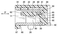
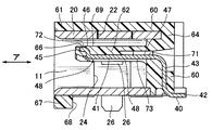
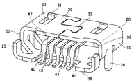
図1乃至図3に、本発明による電気コネクタ1の外観を示す。図1は、正面斜視図、図2は、背面斜視図、図3は、正面図、更に、図4は、図3のa−a線断面図、図5は、b−b線断面図である。図6乃至図10は、これら図1乃至図5にそれぞれ対応する図であるが、便宜上、図1等の状態から絶縁体60を取り除いた状態を示している。
1 to 3 show the appearance of an
電気コネクタ1は、ピッチ方向に複数並列されたコンタクト40と、これらのコンタクト40を遮蔽するシェル20、更に、これらコンタクト40及びシェル20と一体的に一括成形された絶縁体60から成る。
The
実際の使用時には、シェル20の内側である嵌合口11を外部に開放させた状態で電子機器等の本体装置(図示されていない)に組み込まれ、基板に半田付け等によって固定される。尚、嵌合口11は、リコンゴム等の蓋で閉じることが好ましいが、本願の電気コネクタ1では、防水対策が強化されていることから、たとえこれに蓋を付け忘れ、或いは、不完全に取り付けたとしても、嵌合口11から電気コネクタ1の嵌合空間に水が浸入することはあっても、本体装置にまで水が浸入することはない。
In actual use, it is assembled into a main body device (not shown) such as an electronic device with the
コンタクト40は、例えば、平らな金属板(板状体)を打ち抜き、折り曲げることによって形成される。コンタクト40には、嵌合方向(図4及び図5中の矢印「ア」方向)に沿って延びる片持ち梁状の水平の長さ部分41と、一部のみ絶縁体60に埋め込まれた垂直部分43と、基板(図示されていない)に半田付けするために使用される水平の固定部42が含まれる。
The
長さ部分41は、ピッチ方向に複数並列された状態で絶縁体60と一体成形され、略平板状の嵌合突出部62を形成し得る。嵌合突出部62は、電気コネクタ1の組立時には、その略全体がシェル20に内包される。この嵌合突出部62において、長さ部分41のピッチ方向における側面50は、絶縁体60によって長さ部分41の下面48から上面47に向かって略半分程度のみ覆われ(図4の参照番号「65」)、残る略半分程度は露出状態とされる。露出した長さ部分41の下面48は、嵌合口11を通じて挿入されてきた相手側コネクタ(図示されていない)の相手側コンタクト(図示されていない)との接触面として利用できる。
The plurality of
長さ部分41の先端を下面48から上面47に向かって折り曲げることにより折曲部45が形成されている。折曲部45の上面46は、絶縁体を形成する際に金型(図示されていない)と接触していることから、製品の製造後も外部に露出したままである。この先端上面46は、相手側コネクタとの嵌合時に、折曲部45が相手側コネクタと衝突し、樹脂もぐり等によってコンタクト40が破壊される危険を防止したり、相手側コネクタのシェルとの接触を回避するため、略平板状の嵌合突出部62の上面69よりも下側に引っ込めて段部66が形成されている。
A
シェル20は、コンタクト40と同様に、例えば、平らな金属板を打ち抜き、折り曲げることによって形成される。折り曲げられた金属板の縁同士はシェル20の天井部中央にて互いに繋ぎ合わされ、この結果、全体として図3または図8によく現れているように、長辺35と、この長辺35と平行な短辺37と、これら長辺35及び短辺37を連結する側辺36を含む逆台形の略筒状を成す。よって、シェル20は、その中心に貫通孔33を形成し得る。貫通孔33からは、コンタクト40に加え、金型が、相手側コネクタの嵌合方向(図4及び図5中の矢印「ア」方向)に沿って挿入される。金型は、貫通孔33の所定位置にコンタクト40を支持する働きも有する。コンタクト40を支持した状態で金型に樹脂を流し込むため、樹脂の流れによってコンタクト40が振れたり、位置ズレしたりすることはない。このような方法によって、コンタクト40をシェル20の所定位置に確実に固定することができる。尚、金属板を繋ぎ合わせることによってできる合せ目22は、一般には、強度補強のため基板に半田付けされるが(図12に参照番号「102d」で示すように)、本発明では、防水機能を高めるため、これを基板の対向側、つまり、シェル20の天井部側に設けて、合せ目22の隙間を絶縁体60で完全に覆うようにしてある。
Similarly to the
底面38側に傾斜した、側辺36からなるシェル20の左右側面50に、これら左右側面50の中央部を切起こしによって底面38側に向けて垂直に且つ舌片状に突出させることによって、切欠部24と基板実装部(舌片)26とが互いに隣接した状態で形成される。これらの基板実装部26は、基板への半田付けのために使用され得るが、半田付けに使用される部分以外の、基板実装部26の根元部分や、切欠部24は、最終的には絶縁体60によって覆われることになる。よって、孔24から水が浸入することはない。
A notch is formed on the left and right side surfaces 50 of the
絶縁体60は、シェル20の外側の全周を筒状に覆う外装61と、コンタクト40の長さ部分41を利用して形成される嵌合突出部62、更に、シェル20の貫通孔33の背面を閉じる背面部64を含む。
The
特に、基板設置側の外装61は、嵌合口11の前面を覆う部分においては、基板設置側に突出67した状態で設けられているだけであり、嵌合口11の前面以外の部分には設けられていない。基板設置側の外装61を嵌合口11の前面以外の部分には設けないとすることにより、半田付けのためのシェル20の露出部を基板設置側に形成することができ、また、基板設置時における電気コネクタ1の低背化を図ることができる。更に、基板設置側の外装61を基板設置側に突出させた状態で設けるとすることにより、この突出部67の背面側側面68を規制部として用い、電気コネクタ1を、本体装置の基板の縁(図示されていない)に突き当てた状態で配置することを可能とし、嵌合口11側において、基板と電気コネクタ1との間に形成され得る隙間を小さくすることができる。これにより、防水効果を高めることができる。
Particularly, the exterior 61 on the board installation side is only provided in a state of protruding 67 on the board installation side in the portion covering the front surface of the
尚、上に説明したように、シェル20の底面38側は半田付けのための露出部を形成する。露出部等の強度を高めるため、シェル20の背面側の一部を、該シェル20の短辺37からなる底面38側から、長辺35からなる上面39側に向けて、垂直に立ち上げて舌片25を形成し、これらの舌片25を絶縁体60で覆う構造としてもよい。また、シェル20の上面39に、立上部31を形成して、プラグロック片(図示されていない)をロックさせるロック穴30を設けてもよい。この場合、絶縁体60の外装61の上部に、シェル22のロック穴30に対応するロック穴70が形成される。これらのロック穴30、70は、電気コネクタ1の実際の使用時には、外装61に貼った防水テープ(図示されていない)等によって塞がれる。
このように、シェル20に切欠孔24や舌片25、立上部31を設けられた構成であっても、シェル20に絶縁体60を一体成形した際に、切欠孔24は絶縁体60によって埋められ、舌片25および立上部31は絶縁体60によって覆われることによって、絶縁体60とシェル20との連結を強化することができる。
As described above, the
As described above, even when the
次に、この電気コネクタ1の製造方法について説明する。
先ず、片持ち梁状のコンタクト40の長さ部分41を、その先端45から、相手側コネクタとの嵌合方向に沿って、シェル20の貫通孔33に一方の側、つまり、長さ部分41の後端側から挿入する。この結果、コンタクト40は、シェル20の内部に、片持ち梁状に不安定な状態で設置される。
Next, a method for manufacturing the
First, the
次いで、第1の金型を、長さ部分41を挿入した一方の側と同じ側から貫通孔33に挿入し、これとは別に、第2の金型を、貫通孔33の他方の側、つまり、長さ部分41の先端側から挿入する。尚、第1の金型と第2の金型の形状は特に図示されていないが、これらの形状は電気コネクタ1の最終的な形状から容易に想像可能である。
Next, the first mold is inserted into the through-
これら挿入された第1及び第2の金型により、長さ部分41の上面47及び下面48は上下二方向から挟み込まれ、更に、長さ部分41のピッチ方向(水平方向)における側面50は、ピッチ方向において、第1の金型によって挟み込まれる。この結果、コンタクト40は、シェル20において位置合わせされる。より詳細には、長さ部分41の上面47は、貫通孔33の一方の側については第1の金型によって、貫通孔33の他方の側については第2の金型によって、それぞれ位置合わせされ、一方、長さ部分41の下面48は、貫通孔33の一方の側と他方の側に亘って(一方の側と他方の側を繋ぐ部分において)第2の金型によって位置合わせされる。更に、このとき、第1の金型は、長さ部分41のピッチ方向における側面50を、長さ部分41の上面47から下面48に向かって略半分程度覆うようにして、長さ部分をシェル20において位置合わせする。尚、長さ部分41の特に上面47に関して、第1の金型を、その略全体を覆うのではなく、途中位置までしか覆わないようにしたのは、あまりに長い金型を使用すると、成形後にそれを引き抜く際に破損する可能性が高くなり、また嵌合突出部に充分な強度を与えるためである。複数の金型を用いて、複数の箇所でコンタクト40を支持する構成、この例では、上下二方向においては第1の金型と第2の金型を利用して3箇所で支持し、ピッチ方向(水平方向)においては第1の金型によって支持する構成とすることにより、シェルに対するコンタクトの位置を正確に規定することができるとともに、金型に樹脂を流し込んだ際のコンタクトの位置ズレを防ぐことができる。
By the inserted first and second molds, the
金型を設置した後、これらの金型に樹脂を流し込み、コンタクト40及びシェル20を絶縁体60と一体的に一括成形する。これにより、電気コネクタ1は、その略全体を樹脂によって覆われる。尚、コンタクト40及びシェル20は絶縁体60と一体的に一括成形されるため、二重成形に比べて製造コストは安くなる。
After the molds are installed, a resin is poured into these molds, and the
尚、成形後の構造は、勿論、金型の形状に対応する。即ち、長さ部分41の上面47は、第1の金型が接触していた貫通孔33の一方の側における部分71と、第2の金型が接触していた貫通孔33の他方の側における部分72においてのみ、絶縁体60から露出された状態とされ、一方、長さ部分41の下面48は、実質的に、第2の金型が接触していた貫通孔33の一方の側と他方の側に亘る部分73においてのみ、絶縁体60から露出した状態とされる。更に、長さ部分41のピッチ方向における側面50は、第1の金型との接触面に対応して、絶縁体60により、長さ部分41の下面48から上面47に向かって略半分程度のみ覆われた状態で形成される。
Of course, the structure after molding corresponds to the shape of the mold. In other words, the
1 電気コネクタ
11 嵌合口
20 シェル
22 合せ目
33 貫通孔
35 長辺
36 側辺
37 短辺
38 底面
39 上面
40 コンタクト
41 長さ部分
45 先端
46 先端上面
47 上面
48 下面
50 側面
60 絶縁体
62 嵌合突出部
70 ロック穴
DESCRIPTION OF
Claims (4)
前記開口を通じて前記筒状のシェルの内部に位置付けられた部分を有する、ピッチ方向に沿って複数並列に配列されたコンタクトであって、前記筒状のシェルの内部に前記前側の開口を通じて挿入された相手側コネクタの相手側コンタクトと該挿入方向において前記コンタクトの厚み方向における一方の面で接触し得るように該挿入方向に沿って配置されている、前記コンタクトと、
前記複数のコンタクトと前記筒状のシェルに対して一括成形により一体的に取り付けられた絶縁体と、を備えた電気コネクタであって、
前記電気コネクタは、前記後側の開口を前記絶縁体によって塞がれ且つ前記筒状のシェルの前記前側の外周を前記絶縁体によって覆われており、前記複数のコンタクトと前記絶縁体を利用して形成された前記相手側コネクタと嵌合され得る嵌合突出部が前記筒状のシェルの内部に設けられていることを特徴とする電気コネクタ。 A cylindrical shell penetrating through an opening provided on each of the front and rear sides ;
Having an internal position置付only be part of the tubular shell through the opening, a contact arranged in parallel a plurality along the pitch direction, through the front opening into the interior of the front Symbol cylindrical shell The contact disposed along the insertion direction so as to come into contact with the mating contact of the inserted mating connector on one surface in the thickness direction of the contact in the insertion direction;
An electrical connector comprising the plurality of contacts and an insulator integrally attached to the cylindrical shell by batch molding,
In the electrical connector, the opening on the rear side is closed by the insulator, and the outer periphery on the front side of the cylindrical shell is covered by the insulator, and the plurality of contacts and the insulator are used. An electrical connector, characterized in that a fitting protrusion that can be fitted with the mating connector formed in this manner is provided inside the cylindrical shell.
Priority Applications (1)
| Application Number | Priority Date | Filing Date | Title |
|---|---|---|---|
| JP2011175981A JP5738119B2 (en) | 2011-08-11 | 2011-08-11 | Electrical connector |
Applications Claiming Priority (1)
| Application Number | Priority Date | Filing Date | Title |
|---|---|---|---|
| JP2011175981A JP5738119B2 (en) | 2011-08-11 | 2011-08-11 | Electrical connector |
Related Parent Applications (1)
| Application Number | Title | Priority Date | Filing Date |
|---|---|---|---|
| JP2009243500A Division JP4875130B2 (en) | 2009-10-22 | 2009-10-22 | Electrical connector and manufacturing method thereof |
Related Child Applications (1)
| Application Number | Title | Priority Date | Filing Date |
|---|---|---|---|
| JP2013007632A Division JP5683616B2 (en) | 2013-01-18 | 2013-01-18 | Electrical connector |
Publications (3)
| Publication Number | Publication Date |
|---|---|
| JP2011249344A JP2011249344A (en) | 2011-12-08 |
| JP2011249344A5 JP2011249344A5 (en) | 2012-10-25 |
| JP5738119B2 true JP5738119B2 (en) | 2015-06-17 |
Family
ID=45414303
Family Applications (1)
| Application Number | Title | Priority Date | Filing Date |
|---|---|---|---|
| JP2011175981A Expired - Fee Related JP5738119B2 (en) | 2011-08-11 | 2011-08-11 | Electrical connector |
Country Status (1)
| Country | Link |
|---|---|
| JP (1) | JP5738119B2 (en) |
Families Citing this family (1)
| Publication number | Priority date | Publication date | Assignee | Title |
|---|---|---|---|---|
| JP5871709B2 (en) * | 2012-05-10 | 2016-03-01 | 日本航空電子工業株式会社 | Electrical connector and manufacturing method thereof |
Family Cites Families (6)
| Publication number | Priority date | Publication date | Assignee | Title |
|---|---|---|---|---|
| JP3425696B2 (en) * | 1999-11-12 | 2003-07-14 | 日本航空電子工業株式会社 | Thin connector |
| JP2002025718A (en) * | 2000-07-13 | 2002-01-25 | Auto Network Gijutsu Kenkyusho:Kk | Shielding connector |
| JP4036370B2 (en) * | 2003-06-02 | 2008-01-23 | 日本航空電子工業株式会社 | Electrical connector and manufacturing method thereof |
| JP2005235424A (en) * | 2004-02-17 | 2005-09-02 | Yazaki Corp | Electromagnetic wave shield connector |
| JP4184370B2 (en) * | 2005-09-26 | 2008-11-19 | Smk株式会社 | Electrical connector |
| JP4655275B2 (en) * | 2005-12-28 | 2011-03-23 | ミツミ電機株式会社 | Connector device |
-
2011
- 2011-08-11 JP JP2011175981A patent/JP5738119B2/en not_active Expired - Fee Related
Also Published As
| Publication number | Publication date |
|---|---|
| JP2011249344A (en) | 2011-12-08 |
Similar Documents
| Publication | Publication Date | Title |
|---|---|---|
| JP4875130B2 (en) | Electrical connector and manufacturing method thereof | |
| TWI509910B (en) | Connector | |
| KR101897403B1 (en) | Electrical connector and production method thereof | |
| JP5913183B2 (en) | Waterproof connector and manufacturing method thereof | |
| US9985393B2 (en) | Electrical connector having a shielding shell with a pair of side arm soldering legs firmly held by an insulative housing | |
| CN102403618B (en) | The manufacture method of water-proof connector | |
| US9985392B2 (en) | Electrical connector | |
| US9893459B2 (en) | Electrical connector having a tongue portion extending beyond a metallic shell | |
| US10199764B2 (en) | Waterproof electrical connector having a shielding shell with a stepped and recessed structure | |
| JP6368504B2 (en) | Electrical connector | |
| JP2011154804A (en) | Cable connector | |
| JP2012029402A (en) | Connector, electric connection box, and manufacturing method of connector | |
| JP2013054844A (en) | Electric connector | |
| TW201810828A (en) | Electrical connector and method of making the same | |
| CN105474473A (en) | Connector | |
| TW201804682A (en) | Electrical connector | |
| CN204088730U (en) | A kind of water-inlet-proof serial bus connector | |
| JP5683616B2 (en) | Electrical connector | |
| CN102598451B (en) | Connector and connection box | |
| JP5738119B2 (en) | Electrical connector | |
| JP5861205B2 (en) | Manufacturing method of electrical connector | |
| JP2013114988A (en) | Interface connector | |
| TWI633721B (en) | Electrical connector and method of making the same | |
| TWM452506U (en) | Electrical connector | |
| JP2014194854A (en) | Case integrated connector and method of manufacturing the same |
Legal Events
| Date | Code | Title | Description |
|---|---|---|---|
| A521 | Written amendment |
Free format text: JAPANESE INTERMEDIATE CODE: A523 Effective date: 20120910 |
|
| A977 | Report on retrieval |
Free format text: JAPANESE INTERMEDIATE CODE: A971007 Effective date: 20121115 |
|
| A131 | Notification of reasons for refusal |
Free format text: JAPANESE INTERMEDIATE CODE: A131 Effective date: 20121119 |
|
| A521 | Written amendment |
Free format text: JAPANESE INTERMEDIATE CODE: A523 Effective date: 20130118 |
|
| A131 | Notification of reasons for refusal |
Free format text: JAPANESE INTERMEDIATE CODE: A131 Effective date: 20130805 |
|
| A521 | Written amendment |
Free format text: JAPANESE INTERMEDIATE CODE: A523 Effective date: 20130930 |
|
| A02 | Decision of refusal |
Free format text: JAPANESE INTERMEDIATE CODE: A02 Effective date: 20140317 |
|
| A521 | Written amendment |
Free format text: JAPANESE INTERMEDIATE CODE: A523 Effective date: 20140523 |
|
| A911 | Transfer of reconsideration by examiner before appeal (zenchi) |
Free format text: JAPANESE INTERMEDIATE CODE: A911 Effective date: 20140602 |
|
| A912 | Removal of reconsideration by examiner before appeal (zenchi) |
Free format text: JAPANESE INTERMEDIATE CODE: A912 Effective date: 20140801 |
|
| A521 | Written amendment |
Free format text: JAPANESE INTERMEDIATE CODE: A523 Effective date: 20150311 |
|
| A61 | First payment of annual fees (during grant procedure) |
Free format text: JAPANESE INTERMEDIATE CODE: A61 Effective date: 20150421 |
|
| R150 | Certificate of patent or registration of utility model |
Ref document number: 5738119 Country of ref document: JP Free format text: JAPANESE INTERMEDIATE CODE: R150 |
|
| LAPS | Cancellation because of no payment of annual fees |