JP5731716B2 - Folding sheet dispenser with overfill prevention device - Google Patents
Folding sheet dispenser with overfill prevention device Download PDFInfo
- Publication number
- JP5731716B2 JP5731716B2 JP2014535185A JP2014535185A JP5731716B2 JP 5731716 B2 JP5731716 B2 JP 5731716B2 JP 2014535185 A JP2014535185 A JP 2014535185A JP 2014535185 A JP2014535185 A JP 2014535185A JP 5731716 B2 JP5731716 B2 JP 5731716B2
- Authority
- JP
- Japan
- Prior art keywords
- bracket
- dispenser
- cover
- locking element
- mounting frame
- Prior art date
- Legal status (The legal status is an assumption and is not a legal conclusion. Google has not performed a legal analysis and makes no representation as to the accuracy of the status listed.)
- Active
Links
Images


Classifications
-
- A—HUMAN NECESSITIES
- A47—FURNITURE; DOMESTIC ARTICLES OR APPLIANCES; COFFEE MILLS; SPICE MILLS; SUCTION CLEANERS IN GENERAL
- A47K—SANITARY EQUIPMENT NOT OTHERWISE PROVIDED FOR; TOILET ACCESSORIES
- A47K10/00—Body-drying implements; Toilet paper; Holders therefor
- A47K10/24—Towel dispensers, e.g. for piled-up or folded textile towels; Toilet-paper dispensers; Dispensers for piled-up or folded textile towels provided or not with devices for taking-up soiled towels as far as not mechanically driven
- A47K10/32—Dispensers for paper towels or toilet-paper
- A47K10/42—Dispensers for paper towels or toilet-paper dispensing from a store of single sheets, e.g. stacked
- A47K10/424—Dispensers for paper towels or toilet-paper dispensing from a store of single sheets, e.g. stacked dispensing from the bottom part of the dispenser
Description
本発明は一般に、折り畳みシートディスペンサーに関連し、特に過充填防止装置付きの折り畳みシートディスペンサーに関連する。 The present invention relates generally to a foldable sheet dispenser, and more particularly to a foldable sheet dispenser with an overfill prevention device.
ロール状のシート製品のディスペンサーは、ロールの装填が簡単で、ディスペンサーは、装填しすぎや詰め過ぎが非常に困難であるため、単純であり信頼性がある。ただし、ロール状の製品には、いくつかの分配上の問題がある。ほぼ使い尽くしたロールのある単一ロール式のディスペンサーは、不都合な時になくならないように、保守要員が注意深く監視しなければならない。部分的に使い尽くしたロールを交換することは、製品の浪費となる。その上、一部の単一ロール式ディスペンサーは、ロールは、それが使い尽くされ、芯のみが残った状態になるまで、除去できないように設計されている。 The roll sheet product dispenser is simple and reliable because it is easy to load the roll and the dispenser is very difficult to overload and overfill. However, roll products have some distribution problems. Single roll dispensers with nearly used up rolls must be carefully monitored by maintenance personnel so that they do not go away at inconvenient times. Replacing a partially exhausted roll is a waste of product. In addition, some single roll dispensers are designed so that the roll cannot be removed until it is used up and only the wick remains.
ペーパータオルおよびこれに類するものを積み重ねて折り畳んだシートを分配するためのディスペンサーが、当技術でよく知られている。単一シート式ディスペンサーは、部分的に使い尽くしたロールの交換が、著しい製品浪費につながりうるロール製品のディスペンサーと比較して、一般に部分的にだけ使い尽くしたときに補充が可能であるため望ましい。積み重ね式単一シートディスペンサーはまた、詰まりや故障を起こしにくい単純な装置である傾向にあるため望ましい。 Dispensers for dispensing sheets of paper towels and the like stacked and folded are well known in the art. Single sheet dispensers are desirable because replacement of a partially exhausted roll can generally be refilled when partially exhausted compared to a roll product dispenser that can lead to significant product waste. . Stackable single sheet dispensers are also desirable because they tend to be simple devices that are less prone to clogging and failure.
折り畳み式の積み重ねシートディスペンサーの欠点は、過充填、あるいは「詰め込みすぎ」の状態にしてしまいがちなことである。ディスペンサーの過充填は、積み重ねられたシートを圧縮し、ディスペンサーからシートを取り出すことが非常に困難になることがある。例えば、積み重ねに対する圧力は、ユーザーがシートを引き出すために、シートの自由に動くタブまたは端部を掴めなくなるようになりうる。過充填した状態では、積み重ねられたシートは端部が破れるほどしっかりとディスペンサー内に固定されうるので、ユーザーが掴んだシートの部分が、シートを分配する代わりに破れることがある。ディスペンサーの過充填により、分配用開口部に対する摩擦が増大することがあり、分配の信頼性がなくなり、問題となる。 A disadvantage of foldable stacked sheet dispensers is that they tend to be overfilled or “too packed”. Overfilling the dispenser can make it very difficult to compress the stacked sheets and remove the sheets from the dispenser. For example, the pressure on the stack can cause the user to become unable to grip the freely moving tabs or edges of the sheet in order to pull the sheet. In an overfilled state, the stacked sheets can be firmly secured in the dispenser so that the edges are torn, so that the portion of the sheet gripped by the user may be torn instead of dispensing the sheet. Overfilling the dispenser can increase friction against the dispensing opening, which can cause problems with unreliable dispensing.
当技術において、過充填の状態を防止するために、積み重ねられた折り畳み式シートディスペンサーを改善するニーズがなおも存在する。本発明は、こうした改善されたディスペンサーに関連する。 There remains a need in the art to improve stacked foldable sheet dispensers to prevent overfill conditions. The present invention relates to such an improved dispenser.
一般的に述べると、本発明は、単純であるが、効果的な過充填防止装置の付いた折り畳みシートディスペンサーを提供する。 Generally speaking, the present invention provides a foldable sheet dispenser with a simple but effective overfill prevention device.
本発明の一つの実施形態では、本発明は、
a. 積み重ねられた折り畳みシートを保持するよう適合された取付けフレームであって、取付けフレームが、後部パネル、底部および上部を含むものと、
b. 取付けフレームに結合されるカバーであって、カバーが取付けフレームに面する内面と、ディスペンサーの正面を形成する外面を持ち、カバーが内面から延びる少なくとも一つの突起物を持つものと、
c. 取付けフレームの底部に、またはその付近に位置する分配用開口部と、
d. 取付けフレームの上部に、またはその付近に位置する過充填防止装置であって、前記過充填防止装置が、
i. ハウジングに枢動可能に結合された第一のセクション、および反対側の第二のセクションを持つブラケットであって、前記第二のセクションが枢動可能に結合された第一のセクションのまわりを弧状に自由に回転し、
ブラケットが充填位置および分配位置を持ち、またブラケットが、ディスペンサーが積み重ねられた折り畳みシートで充填されたときに、積み重ねられた折り畳みシートに接するように適合されているブラケットと、
ii. ディスペンサーのカバーが開いているとき、ブラケットと噛み合って、ブラケットを充填位置に保持し、ディスペンサーのカバーが閉じているときブラケットを解除するロッキング要素とを備える過充填防止装置を持ち、
ロッキング要素がブラケットを解除してブラケットが前記分配位置に移動できるように、カバーが閉じたときに、カバーの突起物がロッキング要素に噛み合う、折り畳みシートディスペンサー。
In one embodiment of the invention, the invention provides:
a mounting frame adapted to hold stacked folded sheets, the mounting frame including a rear panel, a bottom and a top;
b. a cover coupled to the mounting frame, the cover having an inner surface facing the mounting frame and an outer surface forming the front of the dispenser, the cover having at least one protrusion extending from the inner surface;
c. a dispensing opening located at or near the bottom of the mounting frame;
d. An overfill prevention device located at or near the top of the mounting frame, the overfill prevention device comprising:
i. a bracket having a first section pivotally coupled to the housing and a second section on the opposite side, wherein the second section is pivotally coupled around the first section; Rotate freely in an arc,
The bracket has a filling position and a dispensing position, and the bracket is adapted to contact the stacked folding sheets when the dispenser is filled with the stacked folding sheets;
ii. having an overfill prevention device with a locking element that engages the bracket when the dispenser cover is open, holds the bracket in the filling position, and releases the bracket when the dispenser cover is closed;
A folding sheet dispenser, wherein the projections of the cover engage the locking element when the cover is closed so that the locking element releases the bracket and the bracket can be moved to the dispensing position.
本発明のさらなる実施形態において、ロッキング要素はプレートである。プレートは、第一の端部および反対側の第二の端部を持つ。さらに、プレートは、プレートの第一の端部で、またはその付近で旋回接続によって取付けフレームに結合し、プレートの反対側の第二の端部が、旋回接続のまわりを弧状に自由に移動する。一般に、プレートの第二の端部が、ブラケットに噛み合い、カバーが開いている時にブラケットを充填位置に保持する。本発明の一つの態様では、プレートは、重力を使用してブラケットに噛み合う。 In a further embodiment of the invention, the locking element is a plate. The plate has a first end and an opposite second end. In addition, the plate is coupled to the mounting frame by a pivot connection at or near the first end of the plate, and a second end opposite the plate is free to move arcuately around the pivot connection. . Generally, the second end of the plate engages the bracket and holds the bracket in the filling position when the cover is open. In one aspect of the invention, the plate engages the bracket using gravity.
本発明の追加的実施形態では、ブラケットは、上部分および下部分を持つ。下部分は、ディスペンサー内に積み重ねられた折り畳みシートに接するよう適合され、上部分は、ロッキング要素と噛み合うように適合されている。 In an additional embodiment of the invention, the bracket has an upper portion and a lower portion. The lower part is adapted to contact the folded sheets stacked in the dispenser and the upper part is adapted to engage the locking element.
本発明の別の実施形態では、ブラケットの上部分は、少なくとも一つのスロットをさらに持つ。このスロットは、ロッキング要素がブラケットに噛み合う位置に、またはその付近に位置する。スロットは、カバーの突出部が、ブラケットに噛み合うことなく、ロック要素に噛み合うように構成される。 In another embodiment of the invention, the upper portion of the bracket further comprises at least one slot. This slot is located at or near the position where the locking element engages the bracket. The slot is configured such that the protrusion of the cover engages the locking element without engaging the bracket.
本発明のまた別の実施形態では、過充填防止装置はさらに、ハウジングを持つ。このハウジングは、カバーの突起物がロッキング要素に接することができるよう、開口部がハウジング内に位置するように、少なくとも一つの開口部を備える。 In yet another embodiment of the invention, the overfill prevention device further comprises a housing. The housing comprises at least one opening such that the opening is located in the housing so that the projection of the cover can contact the locking element.
本発明の折り畳み式タオルディスペンサーを提供することにより、従来的な過充填防止装置の欠点が克服されうる。 By providing the foldable towel dispenser of the present invention, the disadvantages of conventional overfill prevention devices can be overcome.
本開示で使用するとき、「comprises」(備える、含む)、「comprising」(備えている、含む)という用語や「comprise」という語根から派生するその他の用語は、述べられた何らかの特徴、要素、整数、手順、または成分の存在を特定する非限定用語であることを意図し、一つ以上のその他の特徴、要素、整数、手順、成分、またはその群の存在もしくは追加を除外することは意図しないことが注目されるべきである。 As used in this disclosure, the terms “comprises” (comprising, including), “comprising” (comprising, including) and other terms derived from the root of “comprise” are intended to describe any feature, element, It is intended to be a non-limiting term that identifies the presence of an integer, procedure, or ingredient, and to exclude the presence or addition of one or more other features, elements, integers, procedures, ingredients, or groups thereof It should be noted that not.
ここで、発明の実施形態を詳細に参照するが、その例を図に示す。それぞれの例は、本発明の限定ではなく、説明の目的で提供されている。例えば、一つの実施形態の一部として図示または記述された特徴は、別の実施形態と共に使用して、またさらなる実施形態を生じうる。本発明は、実施形態に対するこれらおよびその他の改造および変形が含まれ、また本書に記載した例は、本発明の範囲および精神内に収まることが意図される。 Reference will now be made in detail to embodiments of the invention, examples of which are illustrated in the drawings. Each example is provided by way of explanation, not limitation of the invention. For example, features illustrated or described as part of one embodiment can be used with another embodiment to yield a still further embodiment. The present invention includes these and other modifications and variations to the embodiments, and the examples described herein are intended to be within the scope and spirit of the present invention.
本発明についてよりよく理解するために、本明細書の図について全般的に注目する。ディスペンサー10は、積み重ねられた折り畳み個別シートから個別のシートを分配するよう構成されている。本発明のディスペンサーは、積み重ねたものからの個別の折り畳みシートとして利用可能なペーパータオル、ティッシュおよびその他の類似した製品の分配に特に適している。
For a better understanding of the present invention, attention is generally directed to the figures herein. The
また当然のことながら、本発明によるディスペンサー10は、図に示したその全体的な形状、サイズまたは構成に限定されない。当然のことながら、図に示したこれらの特定のディスペンサーは、単に本発明の固有の特徴を組み込みうるディスペンサーの実施形態の例として図示されている。
It will also be appreciated that the
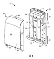
図1に示すとおり、ディスペンサー10には、積み重ねられた折り畳みシート(図1では非表示)を保持するよう適合された取付けフレーム20が含まれる。取付けフレーム20は、底部21および上部22を持ち、下部パネル29は、オプションとして、取付けフレーム20の底部21に、またはその付近に位置する分配用開口部30を持つ。下部パネル29は、取付けフレーム20とは別個の構成要素とすることができ、接着剤、溶接または機械的ファスナーなどの適切な手段を使用して取付けフレーム20と結合されうる。別の方法として、下部パネル29は、取付けプレート20および下部パネル29が一つの単一の部品となるように、取付けプレート20と一体に形成しうる。取付けフレーム20は、後部パネル24も含み、また2つの側壁27および28を持ちうる。下部パネル29は、後部パネル24および側壁27および28がある場合はそれらと共に、取付けフレーム20が積み重ねられた折り畳み物品を保持できる格納スペース26を形成する。
As shown in FIG. 1, the
取付けフレーム20は一般に、ディスペンサー10を支持面に保持する役目をする壁または同種のものなどの支持面に取り付けられる。よって、後部パネル24には、図1に示すとおり、予め形成した穴25など、様々な取付け手段を提供しうるが、ここで、機械的ファスナーを取付けフレームを支持面に固定するために使用しうる。その他の適切な取付け手段を使用することもできる。
The mounting
図1および5の両方を参照すると、ディスペンサー10は、移動できるかたちで取付けフレーム20に取り付けられたカバー40をさらに持つ。カバーは、サイドパネル47、フロントパネルおよび内面44および外面42を持ちうる。図1および5に示すとおり、カバー40は、取付けフレーム20の後部、例えば下部パネル29または側壁27、28に取り付けることができ、また、積み重ねられた折り畳みシートを含むディスペンサーの内部格納スペース26には分配用開口部30を通して以外はアクセスできない、閉じた位置から、追加的な折り畳みシートを格納スペースに装填するための内部格納スペース26への簡単なアクセスが提供される、開いた位置に移動可能である。その閉じた位置では、カバー40は、ディスペンサー10のフロントパネル48を定義する。カバー40は、取付けフレーム20上に位置する旋回取付け機構32並びに、カバー20の内側、特に、カバー20のサイドパネル47上に位置する補完的な旋回取付け機構50によって、取付けフレーム20の固定部に旋回するように取付けられる。図1および5に示す例として、取付け機構32は、取付けフレーム20の下部パネル29にある開口部であり、カバー上の補完的な取付け機構50は、取付け機構の開口部内にフィットするサイズおよび形状を持つ突起物である。当然のことながら、任意の数の従来的な旋回配置が知られており、ディスペンサー10の内部格納スペース26にアクセスするのに邪魔にならないところにカバー40を簡単に移動できる限りは、カバー40を取付けフレーム20に旋回できるように取り付けるために利用しうる。さらに、カバー40は、任意の従来的なロック装置46および取付けフレームに存在する補完的なロック受け34により、取付けフレーム20に着脱できるかたちでロックしうる。当然のことながら、ロック装置は、キー付きまたはキーなしとすることができ、ロック装置の主な目的は、カバー40を閉じた位置に保持することである。
Referring to both FIGS. 1 and 5, the
上述のとおり、ディスペンサー10は、少なくとも一つの分配用開口部30を含む。分配用開口部30は、ユーザーが折り畳みシート12にアクセスする方法であり、折り畳みシート12が、内部格納スペース26から分配される方法である。図1に示す実施形態では、分配用開口部30は、取付けフレームの下部パネル29内に定義される。これは、本発明を限定するものではない。例えば、分配用開口部30は、カバー40の底部またはパネル部材内にも定義されうる。分配用開口部30は、個別の折り畳みシート12を内部格納スペース26から引出し、分配するのにユーザーにとって都合のよい任意の位置に配置しうる。一般に、分配用開口部30は、取付けフレームの底部に、またはその付近に位置し、一般に取付けフレーム20の下部パネル29に位置する。
As described above, the
本発明によるディスペンサー10には、過充填防止装置60が含まれる。過充填防止装置60は、取付けフレーム20の上部に、またはその付近に位置するよう構成されており、サービス技術者が、ディスペンサーの動作が損なわれるポイントまで、ディスペンサーに折り畳みシート12を過充填したり、詰め込みすぎたりしないようにする役目をする。一般的に、過充填防止装置60は、カバー40の動きにより作動される。カバー40を閉じた状態で、積み重ねられたシート12が使い尽くされると、過充填防止装置は、取付けフレーム20内の内部格納スペース26を減少するような位置に自動的に移動する。積み重ねを補充するためにカバー24が開くと、過充填防止装置60が噛み合い、積み重ねの補充のための利用可能なスペースが制限される。積み重ねられたシート12の供給物を補充した後で、カバー40が閉じると、過充填防止装置60の噛み合いが解除され、積み重ねられたシート12に作用する圧縮力が軽減される。
The
特に図2〜4、6〜8を参照すると、過充填防止装置60の実施形態が図示されている。過充填防止装置60は、ブラケット62およびロッキング要素72を持つ。ブラケット62は、ハウジング61に旋回できるように結合された第一のセクション64と、反対側の第二のセクション66とを持つ。さらに、ブラケット62は、ディスペンサー10内の積み重ねられた折り畳みシート12と接触するよう適合された下部分67と、ロッキング要素と噛み合うように適合された上部分68とを持つ。ブラケット62は、ディスペンサー10が、積み重ねられた折り畳みシート12で満たされているとき、ブラケット62の下部分67に沿って第二のセクション66内に積み重ねられた折り畳みシート12に接触するよう適合されている。上述のとおり、ブラケット62は、ハウジングに旋回できるように結合されている。その結果、下記に考察するとおり、ロッキング要素72がブラケット62に噛み合っていないとき、ブラケット62の第二のセクション66は、旋回できるように結合された第一のセクション64の周りを弧65状に自由に回転する。このブラケット62の回転により、結果的にブラケット62が図6に示す充填位置と、図8に示す分配位置を持つことになる。
With particular reference to FIGS. 2-4, 6-8, an embodiment of an
ブラケット62のハウジング61への旋回接続は、任意の従来的な旋回接続手段によって達成しうる。図4に示すとおり、旋回接続は、ブラケット62の第一のセクション64から延びる軸69である。ブラケットの軸69を受けるように適合された補完的なスロット88は、軸69がスロット88にフィットするよう、またブラケット62が軸69およびスロット88により作成される旋回接続のまわりを、図6に示す弧65状に回転するように、ハウジング61上に位置する。図に例示したもの以外にも、本発明の範囲を逸脱することなく、その他の従来的な旋回接続を使用しうる。例えば、ブラケットは、スロットを含むことができ、またハウジングは軸を含むことができる。ハウジング61に旋回できるように結合されたブラケット62を持つことにより、ブラケット62の第二のセクション66は、旋回接続の周りを弧65状に自由に移動する。これにより、カバー40が閉じたとき、ブラケット62が、図6に示す位置から図8に示す位置に回転するようになるが、これについては下記により詳細に記載する。
The pivot connection of the
ロッキング要素72は、ブラケット62と噛み合うように適合され、ディスペンサー10のカバー40が開いているとき、ブラケット62を充填位置に保持する役目をする。さらに、ロッキング要素72は、ディスペンサー40のカバーが閉じたとき、ブラケット62を解除する。ロッキング要素72は、図6に示すとおり、ブラケット62の上部分68に噛み合い、ブラケット62を所定位置に保持し、ブラケット62がディスペンサー10を補充する技術者によって移動しないようにする。これについては、下記にさらに詳しく記載する。
The locking
ロッキング要素72は、図5、6および7に示すとおりプレート73としうる。一般に、ロッキング要素72は、第一の端部78および反対側の第二の端部79を持つ。さらに、ロッキング要素72は、第一の端部78で、またはその付近で旋回接続によって、過充填防止装置60のハウジング61に結合される。図4に示すとおり、旋回接続は、ロッキング要素の第一の端部78から延びる軸76である。軸を受けるよう適合された補完的なスロット86は、ロッキング要素72が旋回接続のまわりを図6に示す弧75状に回転するように、軸76がスロット86にフィットするように、ハウジング61上に位置する。図に例示したもの以外にも、本発明の範囲を逸脱することなく、その他の従来的な旋回接続を使用しうる。例えば、ロッキング要素は、スロットを含むことができ、またハウジングは軸を含むことができる。ハウジング61に旋回できるように結合されたロッキング要素72を持つことにより、ロッキング要素72の反対側の第二の端部79は、旋回接続のまわりを弧75状に自由に移動する。これにより、ロッキング要素72は、ブラケット62が弧65状に回転できるように、カバー40が閉じたとき、ブラケット62の邪魔にならないように移動するようになるが、これについては、下記により詳しく記載する。
The locking
過充填防止装置60は、さらにハウジング61を持つ。上述のとおり、ハウジング61は、ブラケット62およびロッキング要素72の両方に対して旋回接続ポイントとしての役目をする。図に示すとおり、ハウジング61は、取付けフレーム20とは別個の要素であるが、ハウジング61は、取付けフレーム20およびハウジング61が単一の連続した部品となるように、取付けフレーム20と一体としうる。ハウジング61が別個の要素であるとき、ハウジングには一般に取付け手段81が提供され、それにより、機械的ファスナーがハウジング61を取付けフレーム20に取り付けられるようになる。さらに、ハウジング61は、積み重ねられた折り畳みシート12をディスペンサー10に装填して過充填防止装置を無効にするような、技術者による不正操作から、ブラケット62およびロッキング要素72の両方を保護する役目をする。
The
図5を参照するが、カバー40の内面44は、カバー40の内面44から離れて延びる少なくとも一つの突起物84を持つ。カバー40の内面44にある突起物84は、ロッキング要素72に噛み合うように適合され、それによって、ロッキング要素72がブラケット62の上部分68との接触から解除されるようになる。カバーの内部にある突起物は、カバー(非表示)と一体とすることも、適切な締結手段85によって内面44に保持される別個の要素とすることもできる。図5に示すとおり、締結手段85は、機械的ファスナーであるが、その接着により取付け、溶接またはその他の類似した締結手段など、他の適切な締結手段を使用しうる。さらに、内部カバー44にある突起物84がロッキング要素72に接触し、ディスペンサーのカバーが閉じたとき、ロッキング要素72をブラケット62の上部分68から解除する限り、突起物84のサイズおよび形状は、本発明にとって重大ではない。突起物は、例えば、円筒型、立方体状またはその他の類似した形状としうる。
Referring to FIG. 5, the
過充填防止装置60のハウジング61はさらに、少なくとも一つの開口部82を持つ。開口部82により、カバー40の内面44の突起物84が、ハウジング61を通してロッキング要素72に接触し、噛み合うようになる。ハウジングは、一般に、上部表面91、側部表面92および前面93を持つ。一般に、開口部は、ハウジングの前面93内にある。ハウジング61の前面93は、取付けフレーム20に面しないハウジング61の側面である。一般に、ハウジング内の開口部82は、ディスペンサー10のカバー40が閉じたときに、突起物84が開口部84と一列になり、突起物84がロッキング要素72に接触するように、ハウジング内に位置すべきである。開口部のサイズは、突起物84が開口部82に容易に入るものの、成人の手指が開口部82に入るほど大きくはないようにすべきである。開口部82を、成人の手指より小さくすることで、技術者がその手指を使用して過充填防止装置60を無効にすることがより困難になる。一般に、開口部82の少なくとも一つの寸法(直径または幅など)は、7mm未満、さらに一般的には5 mm未満となる。開口部82に加えて、ハウジング61はその内部に、過充填防止装置を無効にしようと試みる技術者を混乱させるための第二の開口部83をさらに持ちうる。第二の開口部83は、一般にロッキング要素72がプローブとは接触できないように位置付けられる。
The
ロッキング要素72は、さらにオプションとして、ロッキング要素74の第二の端部79から延びる一つ以上の脚部74を持ちうる。脚部74は、カバー40が閉じたときに突起物がロッキング要素72に簡単に接するように、ロッキング要素74を開口部82内に延ばす役目をしうる。脚部74はさらに、ロッキング要素に対して追加的な重量を与え、ロッキング要素が充填位置に位置するようになる。
The locking
ブラケット62は一般的に、L字型、三角形または弧形を持つ。L字型のとき、図3および4に示すとおり、ブラケットは、支持部70など、追加的な特徴を持ちうる。支持部70は、ブラケット62に対する構造的な強剛性を与えるのに役立つ。ブラケット62の形状に関係なく、ブラケット62には、ブラケット62上のハウジング61内の開口部82に対応する位置にある一つ以上のスロット63が提供されうる。スロット63は、ブラケット62の図6に示す充填位置から図8に示す分配位置への移動を促進する。スロット63により、ブラケット62は、カバーが閉じるとき、カバー40の内面44の突起物84のまわりを、充填位置から分配位置に移動できるようになる。スロット63はオプションであるが、ハウジング61内の開口部82の位置によっては、スロットが必要となることがある。つまり、前面93で開口部82が低いほど、スロット63がブラケット62に必要となる可能性が高い。
The
本発明において、一般に、カバー20の内面44に位置する少なくとも二つの突起物84があり、ハウジング61内に少なくとも二つ補完的な開口部があり、ロッキング要素の少なくとも二つの脚部74がある。一般に、それぞれ2つがある。単一の突起物を持つことで、開口部または脚部は、突起物が損傷した場合に過充填防止装置が正しく機能しない原因となりうる。さらに、これらの要素をそれぞれ二つ以上持つことで、突起物によりかかる力が、ロッキング要素に対してより均一に分布するようになる。
In the present invention, there are generally at least two
過充填防止装置では、ロッキング要素72およびブラケット62は、重力により、図6に示す充填位置に位置付けられる。つまり、ブラケット62およびロッキング要素の両方にとって自然な状態は、ディスペンサーが空(すなわち、積み重ねられた折り畳みシートが含まれていない)のときでも、あるいはディスペンサーが満杯ではない状態(すなわち、積み重ねられた折り畳みシートが一杯に満たない)でも、図6に示す位置にある。ロッキング要素72およびブラケット62の両方とも、本発明の範囲から逸脱することなく、バネなどの機械的方法を使用して、図6に示す位置にバイアスをかけうることが注目される。ただし、重力が十分である場合には、バイアス手段が使用されないことが好ましい。
In the overfill prevention device, the locking
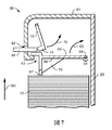
本発明の過充填防止装置60の動作をよりよく理解するために、図6〜8を参照する。図6は、充填位置にある過充填防止装置60を示す。この位置で、重力またはその他のバイアス力によって、ブラケット62およびロッキング要素72の両方が図6の位置になる。この位置で、ロッキング要素72は、ブラケット68の上部分68に噛み合う。これにより、ブラケット62の下部分67が、積み重ね12内に含まれうる折り畳みシートの数を制限するように、ブラケットが図6に示す位置に保持される。一般に、技術者は、最大数の折り畳みシートをディスペンサー10に装填できるように、積み重ね12を圧縮する。これにより、折り畳みシートの圧縮に起因する上向きの力100がブラケット62に対してかかることになる。この上向きの力100によって、ブラケット62の上部分68が、ロッキング要素72に上向きの力をかけるようになる。ロッキング要素72は、実質的に上部分68に対して直角であるため、ロッキング要素72は、ブラケット62の軌道を外れては回転できない。追加的な折り畳みシートがスタック12に追加できなくなると、技術者は一般にカバー40を閉じる。
To better understand the operation of the
技術者がカバー40を閉じると、カバーの内面44の突起物84は、ハウジング61内の開口部82を通って移動する。これに関して、図7を参照する。突起物84が、開口部82を通って移動すると、突起物84は、ロッキング要素72に接触する。カバー40が技術者によって引き続き閉じられると、ロッキング要素72は、旋回ポイント76の周りを弧75状に移動するようになる。ロッキング要素72が、ブラケット62の上部分68から離れると、ブラケット62は、ロッキング要素72から自由になり、圧縮された積み重ねられた折り畳みシート12により発生する力100により、ブラケット62が旋回ポイント69の周りを弧65状に移動するようになる。ブラケット62は、図8に示す位置に類似した位置に弧65状に移動する。ブラケット62が移動する実際の距離は、積み重ねられた折り畳みシート12により発生する力に依存することが注目される。図8に示す積み重ねられた折り畳みシート12’は、図6や図7に示した積み重ねほどは圧縮されていない状態にあることが注目される。出願人は、ブラケット62が移動する必要ないことも注記する。カバー40が閉じる前に、積み重ねられた折り畳みシートが圧縮された状態ではないか、またはわずかしか圧縮されていない場合、ブラケットは、図6に示す位置に留まりうる可能性がある。
When the engineer closes the
個別のシートがディスペンサーから取り出されて、積み重ねが短くなり、ブラケット62が図8に示す位置に実際に移動した場合、ブラケット62は図6に示す位置に戻る。ロッキング要素72は、図8に示す位置に留まるか、またはカバー40が再び開かれるまで、ロッキング要素72が突起物84と接触する位置に戻ることが注目される。十分な数の折り畳みシートが、ディスペンサーから取り出されている場合、いったんカバーが開くと、ロッキング要素は、図6に示す位置に戻る。少数のシートのみが取り出された場合、ロッキング要素は、図8に示す位置のままとなる。
When individual sheets are removed from the dispenser, stacking is shortened, and the
一般に、上述した本発明の折り畳みシートディスペンサーの構成要素は、金属、プラスチックなどを含む任意の適切な材料で形成しうる。こうしたディスペンサーの構造は、当業者にとって周知であり、ここでは詳しく描写する必要がない。 In general, the components of the folding sheet dispenser of the present invention described above can be formed of any suitable material including metal, plastic, and the like. The structure of such dispensers is well known to those skilled in the art and need not be described in detail here.
本発明の利点は、過充填防止装置が単純、低コストであり、また折り畳みシートディスペンサーを扱う技術者によるディスペンサーの過充填を防止するのに効果的な方法であることである。さらに、本発明の過充填防止装置は、問題の原因となることがあり、従来の技術の過充填防止装置に複雑さを加えているバイアス要素を必要とせず機能できる。 An advantage of the present invention is that the overfill prevention device is simple, low cost, and is an effective way to prevent overfilling of the dispenser by technicians working with folded sheet dispensers. Furthermore, the overfill prevention device of the present invention can cause problems and can function without the need for biasing elements that add complexity to the prior art overfill prevention devices.
本発明は、様々な実施形態を参照しながら説明してきたが、当業者であれば、本発明の精神および範囲から逸脱することなく、形状や詳細に変更を加えうることを認識する。よって、上述の詳細な説明は、制限的なものではなく、例証的なものであることが意図され、添付した請求項の範囲、そのすべての等価物を含めたものが、本発明の範囲を定義するものであることが意図される。 Although the present invention has been described with reference to various embodiments, those skilled in the art will recognize that changes can be made in form and detail without departing from the spirit and scope of the invention. Thus, the foregoing detailed description is intended to be illustrative rather than restrictive, and includes the scope of the appended claims, including all equivalents thereof, to the scope of the present invention. It is intended to be defined.
Claims (16)
a.積み重ねられた折り畳みシートを保持するよう適合された取付けフレームであって、前記取付けフレームが、後部パネル、底部および上部を含む取り付けフレームと、
b.前記取付けフレームに結合されたカバーであって、前記カバーが前記取付けフレームに面する内面と、前記ディスペンサーの正面を形成する外面を持ち、前記カバーが前記内面から延びる少なくとも一つの突出部を持つカバーと、
c.前記取付けフレームの前記底部に、またはその付近に位置する分配用開口部と、
d.前記取付けフレームの前記上部に、またはその付近に位置する過充填防止装置であって、前記過充填防止装置が、
1)ハウジングに旋回できるように結合された第一のセクション、および反対側の第二のセクションを持つブラケットであって、前記第二のセクションが前記旋回できるように結合された第一のセクションのまわりを弧状に自由に回転し、前記ブラケットが充填位置および分配位置を持ち、また前記ブラケットが、前記ディスペンサーが積み重ねられた折り畳みシートで充填されたときに、積み重ねられた折り畳みシートに接するように適合されているブラケットと、
2)前記ディスペンサーの前記カバーが開いているとき、前記ブラケットと噛み合って、前記ブラケットを前記充填位置に保持し、前記ディスペンサーの前記カバーが閉じているとき前記ブラケットを解除するロッキング要素とを備え、前記ロッキング要素が少なくとも一つのプレートをさらに備え、各プレートが第一の端部と反対側の第二の端部を持ち、各プレートが、前記第一の端部またはその付近により、前記取付けフレームに対して旋回接続によって結合され、各プレートの前記反対側の第二の端部が、前記旋回接続の周りに弧状に自由に移動し、前記プレートの前記第二の端部が、前記ブラケットに噛み合い、それによって前記カバーが開いたとき前記ブラケットを前記充填位置に保持し、
前記ロッキング要素が前記ブラケットを解除して前記ブラケットが前記分配位置に移動するように、前記カバーが閉じたときに、前記カバーの前記突出部が前記ロッキング要素に噛み合う、過充填防止装置とを備える、折り畳みシートディスペンサー。 A folding sheet dispenser,
a. A mounting frame adapted to hold a stacked folding sheet, the mounting frame comprising a rear panel, a bottom and a top;
b. A cover coupled to said mounting frame, and an inner surface wherein the cover is facing the mounting frame with an outer surface forming a front of the dispenser, with at least one collision detection section said cover extending from said inner surface A cover,
c. A dispensing opening located at or near the bottom of the mounting frame;
d. An overfill prevention device located at or near the top of the mounting frame, wherein the overfill prevention device is
1) a bracket having a first section that is pivotally coupled to the housing, and a second section on the opposite side, wherein the second section is pivotally coupled to the first section; Freely rotates in an arc around the bracket, the bracket has a filling position and a dispensing position, and the bracket is adapted to contact the stacked folding sheets when the dispenser is filled with the stacked folding sheets Brackets that are
2) a locking element that engages with the bracket when the cover of the dispenser is open, holds the bracket in the filling position, and releases the bracket when the cover of the dispenser is closed; The locking element further comprises at least one plate, each plate having a second end opposite the first end, each plate being at or near the first end. engaged binding by the pivotal connection for the second end portion of said opposite side of each plate is free to move in an arc around the pivotal connection, said second end of said plate, Meshing with the bracket, thereby holding the bracket in the filling position when the cover is opened,
An overfill prevention device wherein the protrusion of the cover engages the locking element when the cover is closed so that the locking element releases the bracket and the bracket moves to the dispensing position. , Folding sheet dispenser.
a.積み重ねられた折り畳みシートを保持するよう適合された取付けフレームであって、前記取付けフレームが、後部パネル、底部および上部を含む取り付けフレームと、
b.前記取付けフレームに結合されたカバーであって、前記カバーが前記取付けフレームに面する内面と、前記ディスペンサーの正面を形成する外面を持ち、前記カバーが前記内面から延びる少なくとも一つの突出部を持つカバーと、
c.前記取付けフレームの前記底部に、またはその付近に位置する分配用開口部と、
d.前記取付けフレームの前記上部に、またはその付近に位置する過充填防止装置であって、前記過充填防止装置が、
1)ハウジングに旋回できるように結合された第一のセクション、および反対側の第二のセクションを持つブラケットであって、前記第二のセクションが前記旋回できるように結合された第一のセクションのまわりを弧状に自由に回転し、前記ブラケットが充填位置および分配位置を持ち、また前記ブラケットが、前記ディスペンサーが積み重ねられた折り畳みシートで充填されたときに、積み重ねられた折り畳みシートに接するように適合されているブラケットと、
2)前記ディスペンサーの前記カバーが開いているとき、前記ブラケットと噛み合って、前記ブラケットを前記充填位置に保持し、前記ディスペンサーの前記カバーが閉じているとき前記ブラケットを解除するロッキング要素とを備え、
前記ロッキング要素が前記ブラケットを解除して前記ブラケットが前記分配位置に移動するように、前記カバーが閉じたときに、前記カバーの前記突出部が前記ロッキング要素に噛み合う、過充填防止装置とを備え、
前記ブラケットが上部分および下部分をさらに備え、前記下部分が、前記積み重ねられた折り畳みシートと接触するよう適合され、前記上部分が、前記ロッキング要素と噛み合うように適合され、前記上部分が、少なくとも一つのスロットをも備え、前記スロットが、前記ロッキング要素が前記ブラケットに噛み合う場所、またはその付近に位置し、前記スロットが、前記カバーの前記突出部が前記ブラケットに噛み合うことなく前記ロッキング要素と噛み合うように構成されている、折り畳みシートディスペンサー。 A folding sheet dispenser,
a. A mounting frame adapted to hold a stacked folding sheet, the mounting frame comprising a rear panel, a bottom and a top;
b. A cover coupled to the mounting frame, the cover having an inner surface facing the mounting frame and an outer surface forming a front surface of the dispenser, the cover having at least one protrusion extending from the inner surface. When,
c. A dispensing opening located at or near the bottom of the mounting frame;
d. An overfill prevention device located at or near the top of the mounting frame, wherein the overfill prevention device is
1) a bracket having a first section that is pivotally coupled to the housing, and a second section on the opposite side, wherein the second section is pivotally coupled to the first section; Freely rotating in an arc around the bracket, the bracket has a filling position and a dispensing position, and the bracket is adapted to contact the stacked folding sheets when the dispenser is filled with the stacked folding sheets Brackets that are
2) a locking element that engages with the bracket when the cover of the dispenser is open, holds the bracket in the filling position, and releases the bracket when the cover of the dispenser is closed;
An overfill prevention device, wherein when the cover is closed, the protruding portion of the cover meshes with the locking element so that the locking element releases the bracket and the bracket moves to the dispensing position. ,
The bracket further comprises an upper portion and a lower portion, the lower portion is adapted to contact the stacked folding sheets, the upper portion is adapted to engage the locking element, and the upper portion is At least one slot, wherein the slot is located at or near the location where the locking element engages the bracket, and the slot communicates with the locking element without the protrusion of the cover engaging the bracket. Folding sheet dispenser configured to engage.
Applications Claiming Priority (3)
| Application Number | Priority Date | Filing Date | Title |
|---|---|---|---|
| US13/274,957 US8851326B2 (en) | 2011-10-17 | 2011-10-17 | Folded sheet dispenser with overfill prevention device |
| US13/274,957 | 2011-10-17 | ||
| PCT/IB2012/054716 WO2013057603A1 (en) | 2011-10-17 | 2012-09-11 | Folded sheet dispenser with overfill prevention device |
Publications (3)
| Publication Number | Publication Date |
|---|---|
| JP2014528340A JP2014528340A (en) | 2014-10-27 |
| JP2014528340A5 JP2014528340A5 (en) | 2015-02-19 |
| JP5731716B2 true JP5731716B2 (en) | 2015-06-10 |
Family
ID=47189987
Family Applications (1)
| Application Number | Title | Priority Date | Filing Date |
|---|---|---|---|
| JP2014535185A Active JP5731716B2 (en) | 2011-10-17 | 2012-09-11 | Folding sheet dispenser with overfill prevention device |
Country Status (11)
| Country | Link |
|---|---|
| US (1) | US8851326B2 (en) |
| EP (1) | EP2768368B1 (en) |
| JP (1) | JP5731716B2 (en) |
| KR (1) | KR101548472B1 (en) |
| CN (1) | CN103874444B (en) |
| AU (1) | AU2012324567B2 (en) |
| BR (1) | BR112014008383B1 (en) |
| CA (1) | CA2848645C (en) |
| MX (1) | MX2014003622A (en) |
| RU (1) | RU2572170C2 (en) |
| WO (1) | WO2013057603A1 (en) |
Families Citing this family (8)
| Publication number | Priority date | Publication date | Assignee | Title |
|---|---|---|---|---|
| US10478023B2 (en) * | 2010-11-03 | 2019-11-19 | Solaris Paper, Inc. | Folded towel dispenser with overfill prevention |
| KR200488712Y1 (en) | 2015-06-30 | 2019-03-08 | 유한킴벌리 주식회사 | Sheet tissue paper dispenser |
| USD790873S1 (en) * | 2015-12-28 | 2017-07-04 | Kimberly-Clark Worldwide, Inc. | Multi-fold towel dispenser |
| CN110167408A (en) | 2017-01-09 | 2019-08-23 | 易希提卫生与保健公司 | Dispenser for sheet products and operating method |
| WO2018127302A1 (en) | 2017-01-09 | 2018-07-12 | Sca Hygiene Products Ab | Dispenser for sheet products and operating method |
| US10602890B2 (en) * | 2017-01-09 | 2020-03-31 | Essity Hygiene And Health Aktiebolag | Dispenser for dispensing sheet products |
| KR102314940B1 (en) * | 2017-07-05 | 2021-10-21 | 킴벌리-클라크 월드와이드, 인크. | Dispenser housing |
| USD889161S1 (en) * | 2018-03-26 | 2020-07-07 | Brightwell Dispensers Limited | Paper towel dispenser |
Family Cites Families (18)
| Publication number | Priority date | Publication date | Assignee | Title |
|---|---|---|---|---|
| US1784836A (en) * | 1929-04-12 | 1930-12-16 | Edward C Hess | Envelope feeder |
| US3935965A (en) * | 1974-04-26 | 1976-02-03 | Stevens & Thompson Paper Company | Toilet tissue dispenser |
| US4329001A (en) | 1980-02-05 | 1982-05-11 | Georgia-Pacific Corporation | Dispenser for folded sheets of flexible material |
| US4938382A (en) * | 1987-07-30 | 1990-07-03 | Scott Paper Company | Dispensing cabinet for paper sheets |
| US5102007A (en) * | 1991-03-12 | 1992-04-07 | James River Ii, Inc. | Dispenser for folded sheet products |
| US5076466A (en) | 1991-03-12 | 1991-12-31 | James River Ii, Inc. | Folded sheet product dispenser with anti-overfill mechanism |
| WO1997009918A1 (en) | 1995-09-14 | 1997-03-20 | Kimberly-Clark Worldwide, Inc. | Improved paper towel dispensing mechanism for public washrooms |
| US5884805A (en) * | 1996-10-24 | 1999-03-23 | Kimberly-Clark Corp. | Overfill prevention system for folded sheet dispenser |
| US7845515B2 (en) | 2000-12-11 | 2010-12-07 | Georgia-Pacific Consumer Products Lp | Modified gravity-feed multi-fold towel dispenser |
| US6520372B2 (en) | 2000-12-19 | 2003-02-18 | Kimberly-Clark Worldwide, Inc. | Folded sheet dispenser having an overfill prevention device |
| US6622888B2 (en) | 2001-03-09 | 2003-09-23 | Georgia-Pacific Corporation | Metering napkin dispenser |
| US6592002B2 (en) * | 2001-10-29 | 2003-07-15 | Kimberly-Clark Worldwide, Inc. | Dispenser for dispensing a stack of folded sheet products |
| US6779683B2 (en) | 2002-04-30 | 2004-08-24 | Kimberly-Clark Worldwide, Inc. | Dispenser for dispensing sheet material |
| US7374065B2 (en) * | 2002-10-30 | 2008-05-20 | Kimberly-Clark Worldwide, Inc. | Folded sheet dispenser having an overfill prevention mechanism |
| US6920999B2 (en) * | 2002-10-30 | 2005-07-26 | Kimberly-Clark Worldwide, Inc. | Folded sheet dispenser having an overfill prevention mechanism |
| CN101785642A (en) * | 2004-05-07 | 2010-07-28 | Sca卫生产品股份公司 | Distributor for single folding sheet |
| US7428978B2 (en) * | 2005-05-27 | 2008-09-30 | Kimberly-Clark Worldwide, Inc. | Sheet material dispenser |
| EP1795479B1 (en) * | 2005-12-07 | 2008-10-08 | SCA Hygiene Products AB | End plug for a roll of material, roll of material and retention mechanism in a dispenser |
-
2011
- 2011-10-17 US US13/274,957 patent/US8851326B2/en active Active
-
2012
- 2012-09-11 MX MX2014003622A patent/MX2014003622A/en active IP Right Grant
- 2012-09-11 CA CA2848645A patent/CA2848645C/en active Active
- 2012-09-11 AU AU2012324567A patent/AU2012324567B2/en active Active
- 2012-09-11 JP JP2014535185A patent/JP5731716B2/en active Active
- 2012-09-11 RU RU2014117586/12A patent/RU2572170C2/en active
- 2012-09-11 WO PCT/IB2012/054716 patent/WO2013057603A1/en active Application Filing
- 2012-09-11 EP EP12787506.0A patent/EP2768368B1/en active Active
- 2012-09-11 BR BR112014008383-5A patent/BR112014008383B1/en active IP Right Grant
- 2012-09-11 KR KR1020147009772A patent/KR101548472B1/en active IP Right Grant
- 2012-09-11 CN CN201280050883.6A patent/CN103874444B/en active Active
Also Published As
| Publication number | Publication date |
|---|---|
| EP2768368B1 (en) | 2015-12-30 |
| US8851326B2 (en) | 2014-10-07 |
| JP2014528340A (en) | 2014-10-27 |
| WO2013057603A1 (en) | 2013-04-25 |
| US20130092701A1 (en) | 2013-04-18 |
| RU2572170C2 (en) | 2015-12-27 |
| CN103874444A (en) | 2014-06-18 |
| MX2014003622A (en) | 2014-05-30 |
| KR20140077915A (en) | 2014-06-24 |
| BR112014008383B1 (en) | 2021-01-19 |
| CN103874444B (en) | 2016-11-02 |
| RU2014117586A (en) | 2015-11-27 |
| AU2012324567B2 (en) | 2015-04-09 |
| AU2012324567A1 (en) | 2014-03-27 |
| KR101548472B1 (en) | 2015-08-28 |
| BR112014008383A2 (en) | 2017-04-04 |
| CA2848645A1 (en) | 2013-04-25 |
| CA2848645C (en) | 2015-09-08 |
| EP2768368A1 (en) | 2014-08-27 |
Similar Documents
| Publication | Publication Date | Title |
|---|---|---|
| JP5731716B2 (en) | Folding sheet dispenser with overfill prevention device | |
| US20210068596A1 (en) | Dispenser and stack of sheet products | |
| US7093737B2 (en) | Container and cartridge for dispensing paper products | |
| US7048143B2 (en) | Container and cartridge for dispensing paper products | |
| US20150196176A1 (en) | Folded Sheet Product Cartridges and Dispensing Systems, Assemblies, and Methods | |
| US20060273101A1 (en) | Container and cartridge for dispensing paper products | |
| US20210043023A1 (en) | Product dispensing system | |
| KR20080035516A (en) | Multiple stack dispensing container | |
| US20050040177A1 (en) | Container and cartridge for dispensing paper products | |
| US6920999B2 (en) | Folded sheet dispenser having an overfill prevention mechanism | |
| US20170209006A1 (en) | Mechanical dispenser for perforated sheet products | |
| AU2003253718B2 (en) | A folded sheet dispenser having an overfill prevention mechanism | |
| EP3721775A1 (en) | Dispenser and method of replenishing the dispenser | |
| WO2017086842A1 (en) | Insert dispenser for sheet products, cabinet for mounting an insert dispenser and use of insert dispenser in a cabinet | |
| CN110325084B (en) | Dispenser for dispensing sheet products | |
| AU2005201296B2 (en) | Container and cartridge for dispensing controlled amounts of paper products | |
| US20110163111A1 (en) | Napkin dispenser |
Legal Events
| Date | Code | Title | Description |
|---|---|---|---|
| A521 | Request for written amendment filed |
Free format text: JAPANESE INTERMEDIATE CODE: A523 Effective date: 20141218 |
|
| A621 | Written request for application examination |
Free format text: JAPANESE INTERMEDIATE CODE: A621 Effective date: 20141218 |
|
| A871 | Explanation of circumstances concerning accelerated examination |
Free format text: JAPANESE INTERMEDIATE CODE: A871 Effective date: 20141218 |
|
| A975 | Report on accelerated examination |
Free format text: JAPANESE INTERMEDIATE CODE: A971005 Effective date: 20150218 |
|
| A131 | Notification of reasons for refusal |
Free format text: JAPANESE INTERMEDIATE CODE: A131 Effective date: 20150303 |
|
| A521 | Request for written amendment filed |
Free format text: JAPANESE INTERMEDIATE CODE: A523 Effective date: 20150305 |
|
| TRDD | Decision of grant or rejection written | ||
| A01 | Written decision to grant a patent or to grant a registration (utility model) |
Free format text: JAPANESE INTERMEDIATE CODE: A01 Effective date: 20150407 |
|
| A61 | First payment of annual fees (during grant procedure) |
Free format text: JAPANESE INTERMEDIATE CODE: A61 Effective date: 20150409 |
|
| R150 | Certificate of patent or registration of utility model |
Ref document number: 5731716 Country of ref document: JP Free format text: JAPANESE INTERMEDIATE CODE: R150 |
|
| R250 | Receipt of annual fees |
Free format text: JAPANESE INTERMEDIATE CODE: R250 |
|
| R250 | Receipt of annual fees |
Free format text: JAPANESE INTERMEDIATE CODE: R250 |
|
| R250 | Receipt of annual fees |
Free format text: JAPANESE INTERMEDIATE CODE: R250 |
|
| R250 | Receipt of annual fees |
Free format text: JAPANESE INTERMEDIATE CODE: R250 |
|
| R250 | Receipt of annual fees |
Free format text: JAPANESE INTERMEDIATE CODE: R250 |
|
| R250 | Receipt of annual fees |
Free format text: JAPANESE INTERMEDIATE CODE: R250 |