JP5730870B2 - Method of forming cover sheet with glass frit and glass package having cover sheet with glass frit - Google Patents
Method of forming cover sheet with glass frit and glass package having cover sheet with glass frit Download PDFInfo
- Publication number
- JP5730870B2 JP5730870B2 JP2012520761A JP2012520761A JP5730870B2 JP 5730870 B2 JP5730870 B2 JP 5730870B2 JP 2012520761 A JP2012520761 A JP 2012520761A JP 2012520761 A JP2012520761 A JP 2012520761A JP 5730870 B2 JP5730870 B2 JP 5730870B2
- Authority
- JP
- Japan
- Prior art keywords
- frit
- bead
- seal
- substrate
- cover sheet
- Prior art date
- Legal status (The legal status is an assumption and is not a legal conclusion. Google has not performed a legal analysis and makes no representation as to the accuracy of the status listed.)
- Active
Links
- 239000011521 glass Substances 0.000 title claims description 41
- 238000000034 method Methods 0.000 title claims description 24
- 239000011324 bead Substances 0.000 claims description 168
- 239000000758 substrate Substances 0.000 claims description 78
- 238000007789 sealing Methods 0.000 claims description 12
- 239000000463 material Substances 0.000 description 18
- 238000000151 deposition Methods 0.000 description 12
- 230000004048 modification Effects 0.000 description 4
- 238000012986 modification Methods 0.000 description 4
- 230000008878 coupling Effects 0.000 description 3
- 238000010168 coupling process Methods 0.000 description 3
- 238000005859 coupling reaction Methods 0.000 description 3
- 239000000945 filler Substances 0.000 description 3
- 238000004519 manufacturing process Methods 0.000 description 3
- 239000000203 mixture Substances 0.000 description 3
- 230000005855 radiation Effects 0.000 description 3
- XEEYBQQBJWHFJM-UHFFFAOYSA-N Iron Chemical compound [Fe] XEEYBQQBJWHFJM-UHFFFAOYSA-N 0.000 description 2
- 230000015556 catabolic process Effects 0.000 description 2
- 238000006731 degradation reaction Methods 0.000 description 2
- 239000007772 electrode material Substances 0.000 description 2
- 238000002834 transmittance Methods 0.000 description 2
- RYGMFSIKBFXOCR-UHFFFAOYSA-N Copper Chemical compound [Cu] RYGMFSIKBFXOCR-UHFFFAOYSA-N 0.000 description 1
- 229910052779 Neodymium Inorganic materials 0.000 description 1
- 239000000654 additive Substances 0.000 description 1
- 230000000996 additive effect Effects 0.000 description 1
- 239000011230 binding agent Substances 0.000 description 1
- 230000005540 biological transmission Effects 0.000 description 1
- 230000015572 biosynthetic process Effects 0.000 description 1
- 229910052802 copper Inorganic materials 0.000 description 1
- 239000010949 copper Substances 0.000 description 1
- 230000008021 deposition Effects 0.000 description 1
- 230000006866 deterioration Effects 0.000 description 1
- 238000001125 extrusion Methods 0.000 description 1
- 230000006872 improvement Effects 0.000 description 1
- 150000002500 ions Chemical class 0.000 description 1
- 229910052742 iron Inorganic materials 0.000 description 1
- 230000001678 irradiating effect Effects 0.000 description 1
- 239000007788 liquid Substances 0.000 description 1
- 230000007774 longterm Effects 0.000 description 1
- 238000005259 measurement Methods 0.000 description 1
- QEFYFXOXNSNQGX-UHFFFAOYSA-N neodymium atom Chemical compound [Nd] QEFYFXOXNSNQGX-UHFFFAOYSA-N 0.000 description 1
- 239000011368 organic material Substances 0.000 description 1
- 230000003647 oxidation Effects 0.000 description 1
- 238000007254 oxidation reaction Methods 0.000 description 1
- 239000000843 powder Substances 0.000 description 1
- 230000009467 reduction Effects 0.000 description 1
- 239000005394 sealing glass Substances 0.000 description 1
- 238000005245 sintering Methods 0.000 description 1
- 239000002904 solvent Substances 0.000 description 1
- 230000007704 transition Effects 0.000 description 1
- 229910052720 vanadium Inorganic materials 0.000 description 1
- LEONUFNNVUYDNQ-UHFFFAOYSA-N vanadium atom Chemical compound [V] LEONUFNNVUYDNQ-UHFFFAOYSA-N 0.000 description 1
Images


Classifications
-
- C—CHEMISTRY; METALLURGY
- C03—GLASS; MINERAL OR SLAG WOOL
- C03C—CHEMICAL COMPOSITION OF GLASSES, GLAZES OR VITREOUS ENAMELS; SURFACE TREATMENT OF GLASS; SURFACE TREATMENT OF FIBRES OR FILAMENTS MADE FROM GLASS, MINERALS OR SLAGS; JOINING GLASS TO GLASS OR OTHER MATERIALS
- C03C27/00—Joining pieces of glass to pieces of other inorganic material; Joining glass to glass other than by fusing
- C03C27/06—Joining glass to glass by processes other than fusing
-
- C—CHEMISTRY; METALLURGY
- C03—GLASS; MINERAL OR SLAG WOOL
- C03C—CHEMICAL COMPOSITION OF GLASSES, GLAZES OR VITREOUS ENAMELS; SURFACE TREATMENT OF GLASS; SURFACE TREATMENT OF FIBRES OR FILAMENTS MADE FROM GLASS, MINERALS OR SLAGS; JOINING GLASS TO GLASS OR OTHER MATERIALS
- C03C17/00—Surface treatment of glass, not in the form of fibres or filaments, by coating
- C03C17/02—Surface treatment of glass, not in the form of fibres or filaments, by coating with glass
- C03C17/04—Surface treatment of glass, not in the form of fibres or filaments, by coating with glass by fritting glass powder
-
- H—ELECTRICITY
- H05—ELECTRIC TECHNIQUES NOT OTHERWISE PROVIDED FOR
- H05B—ELECTRIC HEATING; ELECTRIC LIGHT SOURCES NOT OTHERWISE PROVIDED FOR; CIRCUIT ARRANGEMENTS FOR ELECTRIC LIGHT SOURCES, IN GENERAL
- H05B33/00—Electroluminescent light sources
- H05B33/02—Details
-
- H—ELECTRICITY
- H10—SEMICONDUCTOR DEVICES; ELECTRIC SOLID-STATE DEVICES NOT OTHERWISE PROVIDED FOR
- H10K—ORGANIC ELECTRIC SOLID-STATE DEVICES
- H10K50/00—Organic light-emitting devices
- H10K50/80—Constructional details
- H10K50/84—Passivation; Containers; Encapsulations
- H10K50/842—Containers
- H10K50/8426—Peripheral sealing arrangements, e.g. adhesives, sealants
-
- H—ELECTRICITY
- H10—SEMICONDUCTOR DEVICES; ELECTRIC SOLID-STATE DEVICES NOT OTHERWISE PROVIDED FOR
- H10K—ORGANIC ELECTRIC SOLID-STATE DEVICES
- H10K77/00—Constructional details of devices covered by this subclass and not covered by groups H10K10/80, H10K30/80, H10K50/80 or H10K59/80
- H10K77/10—Substrates, e.g. flexible substrates
-
- H—ELECTRICITY
- H10—SEMICONDUCTOR DEVICES; ELECTRIC SOLID-STATE DEVICES NOT OTHERWISE PROVIDED FOR
- H10K—ORGANIC ELECTRIC SOLID-STATE DEVICES
- H10K59/00—Integrated devices, or assemblies of multiple devices, comprising at least one organic light-emitting element covered by group H10K50/00
- H10K59/80—Constructional details
- H10K59/87—Passivation; Containers; Encapsulations
- H10K59/871—Self-supporting sealing arrangements
- H10K59/8722—Peripheral sealing arrangements, e.g. adhesives, sealants
-
- Y—GENERAL TAGGING OF NEW TECHNOLOGICAL DEVELOPMENTS; GENERAL TAGGING OF CROSS-SECTIONAL TECHNOLOGIES SPANNING OVER SEVERAL SECTIONS OF THE IPC; TECHNICAL SUBJECTS COVERED BY FORMER USPC CROSS-REFERENCE ART COLLECTIONS [XRACs] AND DIGESTS
- Y02—TECHNOLOGIES OR APPLICATIONS FOR MITIGATION OR ADAPTATION AGAINST CLIMATE CHANGE
- Y02E—REDUCTION OF GREENHOUSE GAS [GHG] EMISSIONS, RELATED TO ENERGY GENERATION, TRANSMISSION OR DISTRIBUTION
- Y02E10/00—Energy generation through renewable energy sources
- Y02E10/50—Photovoltaic [PV] energy
- Y02E10/549—Organic PV cells
-
- Y—GENERAL TAGGING OF NEW TECHNOLOGICAL DEVELOPMENTS; GENERAL TAGGING OF CROSS-SECTIONAL TECHNOLOGIES SPANNING OVER SEVERAL SECTIONS OF THE IPC; TECHNICAL SUBJECTS COVERED BY FORMER USPC CROSS-REFERENCE ART COLLECTIONS [XRACs] AND DIGESTS
- Y10—TECHNICAL SUBJECTS COVERED BY FORMER USPC
- Y10T—TECHNICAL SUBJECTS COVERED BY FORMER US CLASSIFICATION
- Y10T428/00—Stock material or miscellaneous articles
- Y10T428/24—Structurally defined web or sheet [e.g., overall dimension, etc.]
- Y10T428/24355—Continuous and nonuniform or irregular surface on layer or component [e.g., roofing, etc.]
- Y10T428/24372—Particulate matter
- Y10T428/24421—Silicon containing
Description
本明細書の要旨は、一般に、ガラスパッケージを封止するフリット付きカバーシート、特に、フリット付きカバーシートを形成する方法及びフリット付きカバーシートを有するガラスパッケージを形成する方法である。 The gist of this specification is generally a cover sheet with frits for sealing a glass package, in particular a method for forming a cover sheet with frits and a method for forming a glass package having a cover sheet with frits.
〔関連出願の説明〕
本願は、2009年7月17日に出願された米国特許出願第61/226,342号明細書の権益主張出願である。この米国特許出願の内容及びこの米国特許出願に記載されている刊行物を含む非特許文献及び特許文献の開示内容全体を本明細書の一部とする。
[Description of related applications]
This application is an alleged claim application of US Patent Application No. 61 / 226,342 filed on July 17, 2009. The entire disclosures of non-patent and patent documents, including the contents of this US patent application and the publications described in this US patent application, are hereby incorporated by reference.
米国特許第6,998,776号明細書は、放射線吸収ガラスフリットを用いてガラスパッケージをフリット封止する方法を開示している。一般に米国特許第6,998,776号明細書に記載されているように、ガラスフリットを、第1のガラス基材上に閉じられた線をなして(典型的には、額縁の形で)被着して加熱し、それによりフリットを予備焼結する。次に、第1のガラス基材をフリットが第1の基材と第2の基材との間に位置した状態で第2のガラス基材の頂部に載せる。次いで、レーザビームをフリット上で(典型的には、基材のうちの一方又は両方を通って)移動させてフリットを加熱してこれを融解し、基材相互間に気密シールを形成する。 US Pat. No. 6,998,776 discloses a method of frit sealing a glass package using a radiation absorbing glass frit. As generally described in US Pat. No. 6,998,776, the glass frit is formed in a closed line (typically in the form of a frame) on the first glass substrate. Deposit and heat, thereby pre-sintering the frit. Next, the first glass substrate is placed on top of the second glass substrate with the frit positioned between the first substrate and the second substrate. The laser beam is then moved over the frit (typically through one or both of the substrates) to heat the frit and melt it, forming an airtight seal between the substrates.
このようなガラスパッケージは、有機発光ダイオード(OLED)ディスプレイ装置の製造の際に使用される。例示のOLEDディスプレイ装置は、第1の電極材料が被着されたガラス基材、有機エレクトロルミネッセント材料の1つ又は2つ以上の層及び第2の電極材料を有する。有機エレクトロルミネッセント材料の一特徴は、これが水分と酸化の両方の影響を受けやすく、かくして、有機エレクトロルミネッセント材料の劣化を阻止するために有機エレクトロルミネッセント材料を2枚のガラス基材相互間に気密封止する必要がある。 Such glass packages are used in the manufacture of organic light emitting diode (OLED) display devices. An exemplary OLED display device has a glass substrate coated with a first electrode material, one or more layers of organic electroluminescent material, and a second electrode material. One feature of an organic electroluminescent material is that it is susceptible to both moisture and oxidation, thus making the organic electroluminescent material two glass substrates to prevent degradation of the organic electroluminescent material. It is necessary to hermetically seal between the materials.
OLEDディスプレイ装置は、広汎な商品に組み込まれているので、エレクトロルミネッセント材料の長期劣化を阻止するよう適当に封止されたOLEDディスプレイ装置を製造する能力がますます重要になっている。というのは、エレクトロルミネッセント材料の劣化は、OLED装置が組み込まれている商品の機能発揮を損なう場合が多いからである。 As OLED display devices are incorporated into a wide variety of products, the ability to produce OLED display devices that are properly sealed to prevent long-term degradation of electroluminescent materials is becoming increasingly important. This is because the deterioration of the electroluminescent material often impairs the function of a product in which the OLED device is incorporated.
一実施形態によれば、フリット付きカバーシートを形成する方法が、基材を用意するステップと、最初のフリットビードを基材に被着させるステップとを有する。しかる後、少なくとも1つの追加のフリットビードを基材に被着させて少なくとも1つの追加のフリットビードの底部が隣接のフリットビードの底部に接触し、それにより基材上にフリットシールを形成するようにする。 According to one embodiment, a method for forming a fritted cover sheet includes the steps of providing a substrate and depositing an initial frit bead on the substrate. Thereafter, at least one additional frit bead is applied to the substrate such that the bottom of at least one additional frit bead contacts the bottom of an adjacent frit bead, thereby forming a frit seal on the substrate. To.
別の実施形態では、ガラスパッケージを形成する方法が、第1の基材及び第2の基材を用意するステップと、第1の基材に最初のフリットビードを被着させるステップとを有するのが良い。次に、第1の基材に第2のフリットビードを被着させて第2のフリットビードの底部が最初のフリットビードの底部に接触して第1の基材上にフレーム状フリットシールを形成するようにするのが良い。次に、フリットシールが第1の基材と第2の基材との間に配置されるよう第1の基材を第2の基材上に位置決めするのが良い。次に、第1のシールを加熱して第1の基材と第2の基材との間にシールを形成するのが良い。 In another embodiment, a method of forming a glass package includes providing a first substrate and a second substrate, and depositing an initial frit bead on the first substrate. Is good. Next, a second frit bead is applied to the first base, and the bottom of the second frit bead contacts the bottom of the first frit bead to form a frame-like frit seal on the first base. It is good to do. Next, the first substrate may be positioned on the second substrate such that the frit seal is disposed between the first substrate and the second substrate. Next, the first seal may be heated to form a seal between the first substrate and the second substrate.
別の実施形態では、ガラスパッケージを封止するフリット付きカバーシートが、基材に被着された第1のシールを有する。フリットシールは、基材上の封止領域を包囲するのが良い。フリットシールは、1対のテーパした側壁相互間に延びる頂面を有するのが良い。フリットシールの頂面は、少なくとも3つの一次フリット山部を有するのが良い。隣り合う一次フリット山部相互間の間隔は、約1mm未満であるのが良い。 In another embodiment, a fritted cover sheet that seals a glass package has a first seal applied to a substrate. The frit seal may surround the sealing area on the substrate. The frit seal may have a top surface that extends between a pair of tapered sidewalls. The top surface of the frit seal may have at least three primary frit peaks. The spacing between adjacent primary frit crests may be less than about 1 mm.
追加の特徴及び利点は、次の詳細な説明に記載され、一部は、この説明から当業者には容易に明らかであり又は以下の詳細な説明、特許請求の範囲及び添付の図面を含む本明細書に記載された実施形態を実施することにより認識されよう。 Additional features and advantages will be set forth in the following detailed description, and in part will be readily apparent to those skilled in the art from this description or may include a book including the following detailed description, claims and accompanying drawings. It will be appreciated by implementing the embodiments described in the specification.
上述の概要説明と以下の詳細な説明の両方は、種々の実施形態に関しており、特許請求の範囲に記載された発明の性質及び特性を理解するための概観又は枠組みを提供するようになっていることは理解されるべきである。添付の図面は、種々の実施形態の一層の理解を可能にするために含まれており、本明細書に組み込まれてその一部をなしている。図面は、本明細書において説明する種々の実施形態を記載しており、説明と一緒になって、特許請求の範囲に記載された本発明の原理及び作用を説明するのに役立つ。 Both the foregoing general description and the following detailed description relate to various embodiments and are intended to provide an overview or framework for understanding the nature and characteristics of the claimed invention. That should be understood. The accompanying drawings are included to provide a further understanding of the various embodiments, and are incorporated in and constitute a part of this specification. The drawings describe various embodiments described herein, and together with the description serve to explain the principles and operations of the claimed invention.
次に、ガラスパッケージを封止する際に用いられるフリット付きカバーシートの種々の実施形態を詳細に参照する。可能な場合にはいつでも、同一の参照符号は、同一又は類似の部分を示すために図面全体を通じて用いられる。フリット付きカバーシートの一実施形態が図1に示されており、このフリット付きカバーシートは、全体が参照符号100で示されている。フリット付きカバーシートは、主要構成要素として、透明な基材及びフリットシールを有するのが良い。本明細書において、フリット付きカバーシート、フリット付きカバーシートの形成方法及びフリット付きカバーシートを用いてガラスパッケージ、例えばディスプレイ装置又は類似のガラスパッケージを封止する方法について詳細に説明する。
Reference will now be made in detail to various embodiments of frit cover sheets used in sealing glass packages. Wherever possible, the same reference numbers will be used throughout the drawings to refer to the same or like parts. One embodiment of a cover sheet with frit is shown in FIG. 1, which is generally indicated by
図1を参照すると、一実施形態としてのフリット付きカバーシート100が示されている。フリット付きカバーシート100は、主要構成要素として、透明な基材102を有し、この基材102のフリット塗布面106にフリットシール104が被着されている。基材102に関して本明細書で用いられる「透明」という用語は、次の封止作業においてフリット付きカバーシート100に加えられる輻射エネルギーの特定の波長に関し、少なくとも約90%の透過率を有する基材を意味している。例えば、一実施形態では、基材102は、フリットシール104を加熱するために用いられる約750nm〜約950nmの輻射エネルギーの波長について少なくとも約90%の透過率を有する。本明細書において説明する実施形態では、基材102は、例えばコーニング・インコーポレイテッド(Corning, Inc.)により製造されたEAGLE XG(商標)ガラス又は適当な透過率を有する類似のガラス材料で作られたガラス基材であるのが良い。透明な基材102は、主要構成要素として、裏面(図示せず)と反対側に位置決めされたフリット塗布面106を有するのが良い。
Referring to FIG. 1, a
図1をさらに参照すると、第1のシール104は、基材102のフリット塗布面106上に位置決めされるのが良い。フリットシール104は、フリットシール104が一般に、連続した回路を形成するようそれ自体閉じた線又はバンドの形態をしているフレーム状の形状又はパターンを有し、それにより基材102のフリット塗布面106上の封止領域周りに周囲を定めるよう被着されるのが良い。図1に示されているように、フリットシール104は、フレーム状形状が湾曲した又は丸いコーナー部を有するようフリット塗布面106上に位置決めされるのが良い。図示すると共に本明細書において説明する実施形態では、フリットシール104は、0.5mmを超えるのが良い幅WFS及び約12ミクロン〜約20ミクロンの高さを有する。しかしながら、本明細書において説明する被着方法を用いて幅が0.5mm未満、高さが20ミクロンを超え又は12ミクロン未満であるフリットシールを形成できることは理解されるべきである。
Still referring to FIG. 1, the
一実施形態では、第1のシール104は、ペーストとして被着されるガラスを主成分とするフリット材料である。ペーストは、一般に、ガラス粉末、結合剤(通常、有機)及び/又は揮発性液体ビークル、例えば溶剤を含むのがよい。一実施形態では、フリットシール104は、次の封止作業においてフリットシール104に加えられる輻射エネルギーの波長にマッチし又は実質的にマッチした輻射エネルギーの所定の波長で実質的に光吸収断面を有する耐寒性ガラスフリットで作られている。例えば、ガラスフリットは、鉄、銅、バナジウム、ネオジウム及びこれらの組み合わせを含む群から選択された1種類又は2種類以上の輻射エネルギー吸収イオンを含むのが良い。また、ガラスフリットのCTEがフリット付きカバーシートを後で封着する透明な基材と装置基材の両方のCTEに一層厳密に一致するようにガラスフリットにはガラスフリットの熱膨張率(CTE)を変える充填剤(例えば、反転充填剤又は添加充填剤)をドープするのが良い。理解されるように、ガラスフリットの種々の組成を用いてフリットシールを作っても良い。例えば、適当なフリット組成の幾つかの非限定的な例が米国特許第6,998,776号明細書(発明の名称“Glass Package that is Hermetically Sealed with a Frit and Method of Fabrication”)に開示されており、この米国特許を参照により引用し、その記載内容を本明細書の一部とする。
In one embodiment, the
フリットペーストは、押し出し型アプリケータがフリットペーストのビードをノズルを通って基材102上に小出しすることによりフリットシール104を形成するよう基材102に被着されるのが良い。結果的に得られるフリットビードの形状は、一般に、フリットペーストを基材上に小出しするために用いられるノズルのサイズで決まる。例えば、0.6mmの幅WFBを有するフリットビードを被着させるためには、約0.55mmの直径を有するノズルを用いるのが良い。しかしながら、これよりも小さな又は大きなノズルを用いても所望の幅を有するフリットビードを被着させることができることは理解されよう。所望の寸法及びパターンを備えたフリットシールを達成するため、アプリケータは、コンピュータ制御位置決めシステム、例えばロボットアーム又は計算機数値制御(CNC)位置決めシステムに結合されるのが良く、このようなコンピュータ制御位置決めシステムは、フリットペーストをアプリケータから小出ししているときにアプリケータを基材上で操作する。コンピュータ制御位置決めシステムは、アプリケータを所望のパターンのフリットビードの被着を容易にする所定のパターンで巧みに操るようプログラムされるのが良い。
The frit paste may be applied to the
図示すると共に本明細書において説明する実施形態では、フリットシール104は、複数個の個々のフリットビードを所望のパターン(例えば、フレーム状パターン又は類似のパターン)で基材102に被着させて各フリットビードが隣接のフリットビードに接触すると共に/或いはこれとオーバーラップし、それにより所望幅のフリットシール104を形成することによって基材102上に形成されるのが良い。例えば、幅WFSを有するフリットシール104を形成するためには、幅WFB<WFSを有する最初のフリットビードを基材102に被着させるのが良い。しかる後、幅WFB<WFSを有する少なくとも1つの追加のフリットビードを基材102に被着させて少なくとも1つの追加のフリットビードが隣接のフリットビードの底部に当接し又はこれとオーバーラップし、それにより所望幅WFSを有するフリットシール104を形成するようにするのが良い。
In the embodiment shown and described herein, the
次に図1並びに図2A及び図2Bを参照すると、フリット付きカバーシート100を形成する方法の一実施形態が図示されている。この実施形態では、複数個のフリットビード108a,108bを基材102のフリット塗布面106に被着させて所望の幅を有するフリットシール104aを形成するのが良い。この方法の基本的原理を説明するため、フリットビード108a,108bは、理想化された長方形断面を有するものとして示されており、その結果、フリットビード108a,108bは各々、頂面132a,132bに平行な底部130a,130b及び互いに平行な側部134a,136a及び134b,136bを有するようになっている。各フリットビード108a,108bの底部130a,130bは、一般に幅WFBを有し、幅WFBは、この実施形態では、対応の頂面132a,132bの幅でもある。
Referring now to FIG. 1 and FIGS. 2A and 2B, one embodiment of a method for forming a fritted
第1のフリットビード108aは、アプリケータをフリットペーストがアプリケータのノズルから小出しされているときに所定のパターンをなしてフリット塗布面106上で移動させることにより基材102のフリット塗布面106に被着されるのが良い。例えば、本明細書において説明する実施形態では、所望のパターンは、図1に示されているように湾曲した又は丸いコーナー部を備えた長方形のフレーム状パターンである。しかる後、第2のフリットビード108bを第1のフリットビード108aと同様な仕方で基材102のフリット塗布面106に被着させるのが良い。第2のフリットビード108bは、先行するフリットビード(即ち、第1のフリットビード108a)に隣接して被着されて第2のフリットビード108bの側壁134bが第1のフリットビード108aの側壁136aに直に接触すると共にこれに当接するようにするのが良い。したがって、この実施形態では、第2のフリットビード108bの少なくとも底部130bは、第1のフリットビード108aの対応の底部130aに接触し、その結果、第1のフリットビード108aと第2のフリットビード108bは、一緒になって、フリットシール104aを形成し、従って、フリットシール104aが幅WFS=2・WFBを有するようになっている。
The
種々の幅WFBの2つ又は3つ以上のフリットビードを被着させると所望の幅WFSを有するフリットシールを形成することができることは理解されるべきである。例えば、1.2mmの幅WFSを有するフリットシール104aが望ましい場合、各々の幅が0.6mmの第1及び第2のフリットビード108a,108bを本明細書において説明するように基材102のフリット塗布面106に被着させるのが良く、その結果、フリットシール104aは、1.2mmの幅を有するようになる。1.5mmの幅を有するフリット幅が望ましい場合、各々の幅が0.5mmの3つのフリットビードを被着させて所望の幅を有するフリットシールを形成するのが良い。したがって、本明細書において説明した仕方で小さな幅の2つ又は3つ以上のフリットビードを被着させることにより所望の幅をもつフリットシールを形成できることは理解されるべきである。
It should be understood that applying two or more frit beads of various widths W FB can form a frit seal with the desired width W FS . For example, if a
本明細書において注目されるように、図2Bに示されたフリットビード108a,108bは、理想化された長方形断面を有している。しかしながら、他の実施形態では、アプリケータにより小出しされるフリットビードは、テーパした形状を有しても良く、それにより、連続して位置するフリットビードが互いに接触すると共にオーバーラップして所望の幅を有するフリットシールを形成することが必要である。
As noted herein, the
例えば、図3A及び図3Bを参照すると、2つの実施形態としてのフリットビード302,330の断面が示されており、この場合、フリットビード302,330は、テーパした形態を有している。一実施形態では、アプリケータにより小出しされたフリットビード302は、頂面310に向かってテーパしている側壁306,308を備えた底部304を有するのが良い。したがって、頂面310は、底部304よりも幅が狭いことは理解されるべきである。図3Aに示された実施形態としてのフリットビード302では、側壁306,308は、丸いコーナー部で頂面310に移行している。図3Bに示された変形実施形態では、フリットビード330は、弓形頂面320に向かってテーパしている側壁306,308を備えた底部304を有している。したがって、アプリケータにより小出しされたフリットビードは、底部から頂面に向かってテーパしている側壁を備えたテーパ形態を有するのが良いことは理解されよう。いずれの実施形態においても、フリットビードの幅WFBは、フリットビードの底部の幅である。
For example, referring to FIGS. 3A and 3B, cross-sections of two embodiments of
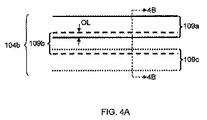
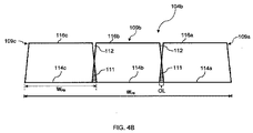
次に図1、図4A及び図4Bを参照すると、テーパした形態を有する複数個のフリットビードからフリットシール104bを形成するため、各フリットビードを基材102のフリット塗布面106に被着させて各フリットビードの底部が隣接のフリットビードの底部に接触してこれとオーバーラップするようにするのが良い。例えば、図4A及び図4Bを参照すると、フリットシール104bが3つの互いにオーバーラップしたフリットビード109a,109b,109cで作られている一実施形態としてのフリットシール104bが示されている。図4Aに示されているように、各フリットビードの底部は、隣接のフリットビードの底部とオーバーラップしている。互いにオーバーラップしているフリットビードの各々は、幅WFBを有すると共に説明の目的上、台形として示されているテーパした断面形状を有している。
Next, referring to FIGS. 1, 4A and 4B, in order to form the
上述したようにフリットペーストをアプリケータのノズルから小出ししているときにアプリケータを所定のパターンでフリット塗布面106上で移動させることにより最初のフリットビード109aを基材102のフリット塗布面106に被着させるのが良い。しかる後、少なくとも1つの追加のフリットビードをフリット塗布面106に被着させて少なくとも1つの追加のフリットビードが隣接のフリットビードの底部に接触すると共にこれとオーバーラップするようにする。この例では、第2のフリットビード109bを基材102のフリット塗布面106に被着させて第2のフリットビード109bの底部114bが第1のフリットビード109aの底部114aとOLで示されている量だけオーバーラップするようにする。フリットビード109a,109bのテーパした形態に起因して、説明の目的で図4Bに示されているフリットビード109a,109b相互間のオーバーラップ領域111のガラスフリット材料は、実際に、フリットビード109aの頂面116aとフリットビード109bの頂面116bとの間の領域112に被着され、それにより、第1のフリットビード109aと第2のフリットビード109bとの間に連続した頂面が形成されている。
As described above, when the frit paste is dispensed from the nozzle of the applicator, the
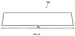
しかる後、第3のフリットビード109cを被着させて第3のフリットビード109cの底部114cが第2のフリットビード109bの底部114bに接触すると共にこれとオーバーラップし、それにより、第3のフリットビード109cと第2のフリットビード109bと第1のフリットビード109aとの間に連続した頂面が形成されるようにするのが良い。この方法は、追加のフリットビードを同様な仕方で被着させ、ついには、フリットシール104bが図4Cに示されているように所望の幅WFSを備えるようにすることにより繰り返されるのが良い。
Thereafter, the third
例えば、テーパした断面形状を有すると共に0.6mmの幅WFBを有する5つのフリットビードを被着させることにより2.6mmの幅WFSを有するフリットシールを形成することができる。フリットビードを各フリットビードの底部が隣接のフリットビードの底部に接触してこれと約0.1mmだけオーバーラップし、それにより2.6mmの幅WFSを有するフリットシールを形成するよう被着させることができる。 For example, a frit seal having a width W FS of 2.6 mm can be formed by depositing five frit beads having a tapered cross-sectional shape and a width W FB of 0.6 mm. Frit beads are deposited so that the bottom of each frit bead contacts the bottom of an adjacent frit bead and overlaps it by about 0.1 mm, thereby forming a frit seal having a width W FS of 2.6 mm. be able to.
図示すると共に本明細書において説明する長方形及びテーパした形態のフリットビードの両方の実施形態及び実施例では、フリットビードは、一般に、約1mm未満の幅FBを有するものとして説明され、このようなフリットビードで形成されたフリットシールは、約1mmより大きい幅WFSを有する。さらに、オーバーラップが、約1mm未満の幅を有するフリットビードと関連して用いられる場合、隣り合うフリットビード相互間のオーバーラップの量は、約0.05mm〜約0.5mmであるのが良い。しかしながら、理解されるべきこととして、これら幅及びオーバーラップ量は、例示であり、本明細書において説明するフリットシールを形成する技術を用いると約1mm未満の幅を有するフリットシールを形成することができ、フリットビードが互いにオーバーラップする場合、オーバーラップ量は、0.05mm未満であっても良く、或いは、約0.5mmより大きくても良い。さらに又、本明細書において説明するフリットシールを形成する技術を約1mmより大きい幅を有するフリットビードと関連して用いることも可能であることは理解されるべきである。 In both rectangular and tapered form frit bead embodiments and examples illustrated and described herein, the frit bead is generally described as having a width FB of less than about 1 mm, and such a frit A frit seal formed of beads has a width W FS greater than about 1 mm. Further, when the overlap is used in connection with frit beads having a width of less than about 1 mm , the amount of overlap between adjacent frit beads may be from about 0.05 mm to about 0.5 mm. . However, it should be understood that these widths and overlap amounts are exemplary, and using the frit seal forming techniques described herein can form a frit seal having a width of less than about 1 mm. If the frit beads overlap each other, the overlap amount may be less than 0.05 mm or may be greater than about 0.5 mm. It should be further understood that the techniques for forming a frit seal described herein can be used in connection with a frit bead having a width greater than about 1 mm.
さらに、図示すると共に本明細書において説明する実施形態及び実施例は、実質的に同一幅の多数のフリットビードを被着させることによるフリットシールの形成に関するが、種々の幅の多数のフリットビードを本明細書において説明する技術の使用により適当な幅のフリットシールを形成するよう被着させることができるということは理解されるべきである。 Further, while the embodiments and examples illustrated and described herein relate to the formation of a frit seal by depositing a number of frit beads of substantially the same width, a number of frit beads of various widths may be used. It should be understood that the technique described herein can be applied to form a suitable width frit seal.
次に図1及び図5を参照すると、本明細書において説明する多パス被着技術を用いてフリットシールをフレーム状の形で被着させてフリットシールが図1に示されているように連続した回路を形成するようそれ自体閉じるようにすることができ、この場合、フリットシール104は、基材102のフリット塗布面106上に丸いコーナー部を備えたフレームを形成する。したがって、フリットシール104を少なくとも1つの湾曲した部分を有するパターンで被着させることができることは理解されよう。フレーム又はパターンの湾曲部分の所望のオーバーラップ(又はオーバーラップのない状態)を維持するため、連続して被着されたフリットビードの各々の曲率半径は、先に被着されたフリットビードとは異なっていても良い。図5を参照すると、フリットシール104bを形成するフリットビードの曲率半径は、フリットビードの中央のところに位置した線、例えば、中心線CL1,CL2,CL3の曲率半径を意味している。所望の曲率半径を有するフリットビードを形成するため、アプリケータをフリットペーストがアプリケータから小出しされているときに対応の中心線の曲率半径をもつ弧を描いて基材上を移動させる。
Referring now to FIGS. 1 and 5, the multi-pass deposition technique described herein is used to deposit the frit seal in the form of a frame so that the frit seal is continuous as shown in FIG. In this case, the
フリットシール104bを基材の内側から基材の縁まで(例えば、フリットビード109aからフリットビード109cまで)形成する場合、連続して被着されたフリットビードの各々は、先のフリットビードの中心線曲率半径よりも大きいフレーム状パターンの湾曲部分の中心線曲率半径を有するのが良い。これとは逆に、フリットシール104bを基材の縁から基材の中央に向かって(例えば、フリットビード109cからフリットビード109aまで)形成する場合、連続して被着されたフリットビードの各々は、先のフリットビードの中心線曲率半径よりも大きい中心線曲率半径を有するのが良い。
When the
一実施形態では、フリットシール104bを形成するよう被着された各フリットビードの中心線曲率半径は、フリットビードを被着させているパターンの湾曲部分の内側半径(RI)、各フリットビードの幅(WFB)、隣り合うフリットビード相互間のオーバーラップ量(OL)及びフリットビードの被着パス回数(P)に基づいて定められる。
In one embodiment, the centerline curvature radius of each frit bead deposited to form the
例えば、3つの互いにオーバーラップしたフリットビード(即ち、P=3)を被着させることにより形成された図5に示されているフリットシール104bを参照すると、フリットシールの最も内側のフリットビード、特にフリットビード109aの中心線曲率半径R1は、次の方程式を用いて計算できる。
![]()
![]()
次のその隣りのフリットビード、即ちフリットビード109bの中心線曲率半径R2は、次のように書き表される。
![]()
![]()
次の隣りのフリットビード109cの中心線曲率半径R3は、次のように書き表される。
![]()
![]()
したがって、上記に基づいて、P個のフリットビードを有するフリットシール中のJ番目のフリットビードの中心線曲率半径RJは、次のように書き表される。
![]()
上式において、Jは、1からPまでの整数である(即ち、1個のフリットビードから全ての数のフリットビード)。以下の表1は、内側曲率半径RIが1mmであり、全幅が1.6mmのフリットシールを形成するよう各々が0.6mmの幅WFB及び約0.1mmのオーバーラップ量OLを有する3つの連続して位置するフリットビードの各々の中心線曲率半径の計算値を示している。
Therefore, based on the above, the center line curvature radius R J of the J-th frit bead in the frit seal having P pieces of frit beads is expressed as follows.
![]()
Where J is an integer from 1 to P (ie, one frit bead to all numbers of frit beads). The following Table 1 is a 1mm inner radius of curvature R I, 3 the overall width, each having a 0.6mm width W FB and about 0.1mm overlap amount OL to form the frit seal of 1.6mm The calculated value of the centerline curvature radius of each of two consecutive frit beads is shown.
表1:中心線曲率半径の計算値

別の実施形態では、フリットビードが被着されているコーナー部の内側半径(RI)、フリットシールの所望の幅(WFS)、隣り合うフリットビード相互間のオーバーラップ量(OL)及びフリットシールを構成するフリットビードの個数(P)と関連して上記の方程式(4)を利用して各フリットビードの中心線曲率半径を求めることができる。この実施形態では、各フリットビードの幅WFBをフリットシールの幅WFS、フリットビードの個数P及びオーバーラップ量OLに基づいて計算することができ、従って、次の通りである。
WFB=(WFS/P)+OL{(P−1)/P)} (5)
In another embodiment, the inner radius (R I ) of the corner to which the frit bead is applied, the desired width of the frit seal (W FS ), the amount of overlap between adjacent frit beads (OL) and the frit The centerline curvature radius of each frit bead can be obtained using the above equation (4) in relation to the number of frit beads (P) constituting the seal. In this embodiment, the width W FB of each frit bead can be calculated based on the width W FS of the frit seal, the number P of frit beads, and the overlap amount OL.
W FB = (W FS / P) + OL {(P−1) / P)} (5)
WFBの計算値を方程式(4)に代入し、各フリットビードの中心線曲率半径をJ個のフリットビードの各々について計算することができ、この場合、Jは、1からPまでの整数である。 Substituting the calculated value of W FB into equation (4), the centerline curvature radius of each frit bead can be calculated for each of the J frit beads, where J is an integer from 1 to P is there.
変形例として、フリットビード幅は既知であるが、フリットシールの全幅が未知である場合、方程式(5)は、次のように書き直せる。
![]()
方程式(6)を用いて、結果として得られるフリットビードの幅を被着されたフリットビードの幅、個数及びオーバーラップ量に基づいて求めることができる。
As a variant, if the frit bead width is known, but the full width of the frit seal is unknown, equation (5) can be rewritten as:
![]()
Using equation (6), the resulting frit bead width can be determined based on the width, number of overlapped frit beads and the amount of overlap.
中心線曲率半径を最終的にフリットシール104bを形成するフリットビードのパターン中の各フリットビードについて計算によりいったん求めると、選択したオーバーラップ量OL及び中心線曲率半径の計算値を用いてフリットビードの各々を基材のフリット塗布面に被着させるのが良く、それにより所望の幅WFSを備えた第1のシール104bが形成される。
Once the center line radius of curvature is determined by calculation for each frit bead in the frit bead pattern that ultimately forms the
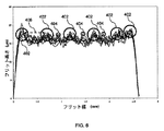
次に図6を参照すると、本明細書において説明する一実施形態に従って形成されたフリットシールの複数個の断面についてフリット幅とフリット高さの関係のグラフ図が示されている。各々が0.6mmの幅を有する5つのフリットビードを被着させることにより透明な基材上に形成された1.6mmフリットシールから輪郭形状に関する測定値を取った。隣り合うフリットビード相互間のオーバーラップ量は、0.1mmであった。フリットシールの互いに異なる断面スライスの輪郭形状をWerth Fixed Bridge Inspector(登録商標)FQ多センサ座標測定機械で計測した。 Referring now to FIG. 6, a graphical representation of the relationship between frit width and frit height for a plurality of cross-sections of a frit seal formed in accordance with one embodiment described herein is shown. Profile measurements were taken from a 1.6 mm frit seal formed on a transparent substrate by depositing 5 frit beads each having a width of 0.6 mm. The amount of overlap between adjacent frit beads was 0.1 mm. The contour shapes of the different slices of the frit seal were measured with a Werth Fixed Bridge Inspector® FQ multi-sensor coordinate measuring machine.
図6に示されているように、フリットシールの頂面は、全体として高さ(例えば、山部の先端部からその隣りの谷部の底まで)約10ミクロン未満の一連の山部と谷部を有するのが良く、従って、フリットシールの頂面は、一般に、フリットシールの幅全体にわたり約±5ミクロンのばらつきを有するようになる。山部は、2つのカテゴリにグループ分け可能である。山部の第1のカテゴリは、フリットシールを構成するフリットビードの外側縁部(例えば、フリットシールの外側縁部)と内側縁部(例えば、隣り合うフリットビードの交差部又はオーバーラップ)の両方のところに形成された一次フリット山部又はピーク402である。一実施形態では、本明細書において説明する技術に従って形成されたフリットシールは、一般に、少なくとも3つの一次フリット山部を有する(即ち、フリットシールは、少なくとも2つのフリットビードを被着させることにより形成される)。山部の第2のカテゴリは、一次フリット山部402相互間に形成される二次山部404である。二次フリット山部404は、一般に高さと幅の両方が一次フリット山部402よりも小さい。
As shown in FIG. 6, the top surface of the frit seal is generally a series of peaks and valleys that are less than about 10 microns in height (eg, from the top of the peak to the bottom of the adjacent valley). Therefore, the top surface of the frit seal will generally have a variation of about ± 5 microns across the width of the frit seal. Mountains can be grouped into two categories. The first category of peaks is both the outer edge of the frit bead (eg, the outer edge of the frit seal) and the inner edge (eg, the intersection or overlap of adjacent frit beads) that make up the frit seal. These are the primary frit peaks or
隣り合う一次フリット山部402相互間の間隔406を減少させることにより、フリットシールとフリット付きカバーシートが封着される装置基材との機械的接触具合を向上させることができる。機械的接触具合の向上により、フリットシールとフリット付きカバーシートが封着された装置基材との熱的結合度が向上し、その結果、封止中に生じる熱が均一に消散する。さらに又、フリットシールとフリット付きカバーシートが封着される装置基材との機械的結合により、フリット付きカバーシートを装置基材に封着するのに必要な力の大きさは減少する。熱的結合の向上と封止力の減少は、封止される装置基材が、過度の熱及び/又は大きい封止力がエレクトロルミネッセント材料、エレクトロルミネッセント材料に結合されたリード及び/又は他の回路を損傷させる場合のあるディスプレイ装置、例えばOLEDディスプレイに用いられる場合に特に重要である。隣り合う一次フリット山部402相互間の間隔406の減少は、被着されたフリットビードの幅を減少させることによって達成できる。
By reducing the
したがって、一実施形態では、本明細書において説明する方法を利用すると、形成されたフリットシールとフリット付きカバーシートが封着された装置基材との機械的接触具合を向上させることができる。所望の機械的及び熱的性質を備えたフリットシールが本明細書において説明した技術を用いて1mm未満の幅を有する複数個のフリットビードを被着させることにより形成でき、その結果、フリットシールの頂面上の隣り合う一次フリット山部相互間の間隔が約1mm以下になる。 Therefore, in one embodiment, the method described herein can be utilized to improve the mechanical contact between the formed frit seal and the device substrate to which the cover sheet with frit is sealed. A frit seal with the desired mechanical and thermal properties can be formed by depositing a plurality of frit beads having a width of less than 1 mm using the techniques described herein, so that the frit seal The distance between adjacent primary frit crests on the top surface is about 1 mm or less.
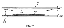
次に図7A及び図7Bを参照すると、本明細書において説明したように形成されたフリット付きカバーシートを用いて装置基材を封止し、それによりガラスパッケージを形成することができる。図7A及び図7Bに示された実施形態では、フリット付きカバーシート100は、エレクトロルミネッセント素子216及び少なくとも1本の電気リード215が設けられた装置基材218を封止して、ガラスパッケージを形成するよう使用されており、なお、ガラスパッケージは、この実施形態ではディスプレイ装置220である。例えば、エレクトロルミネッセント素子は、OLEDであるのが良い。
Referring now to FIGS. 7A and 7B, the cover substrate with frit formed as described herein can be used to seal the device substrate, thereby forming a glass package. In the embodiment shown in FIGS. 7A and 7B, the frit-covered
まず最初に、フリット付きカバーシート100を装置基材218上に位置決めしてエレクトロルミネッセント素子216がフリット付きカバーシート100のフリット塗布面106と装置基材218との間に位置決めされるようにする。フリット付きカバーシート100がこの位置にある状態で、エレクトロルミネッセント素子216をフリットシール104により画定された周囲又はフレーム内に位置決めする。電気リード215は、フリットシール104の下に延びるのが良い。しかる後、フリットシール104を適当な輻射エネルギー222(ブロック矢印で表されている)で照射し、その手段として、フリット付きカバーシート100を通して輻射エネルギー222を差し向ける。幾つかの実施形態では、輻射エネルギー222は、フリットシール104により吸収される波長を有するレーザビームであるのが良い。例えば、適当な波長を有するレーザビームをフリット付きカバーシート100上で移動させてフリットシール104を照射してこれを加熱する。
First, the
フリットシール104を照射する適当な源及び方法は、加熱して融解されるべきフリット組成並びに封着されているガラスパッケージの特性(例えば、熱に敏感な有機材料がガラスパッケージの製造の際に用いられるかどうか)で決まる。フリットシール104に差し向けられた輻射エネルギーは、フリットシール104を加熱してこれを融解させる。フリットシール104が冷えると、フリットシール104は、カバーシート100を装置基材218及びエレクトロルミネッセント素子216から延びている電気リード215に結合し、それによりフリット付きカバーシート100を装置基材218に封着し、それにより気密封止ガラスパッケージ、例えば、この例ではディスプレイ装置220が構成される。
Suitable sources and methods for irradiating the
図7A及び図7Bは、ディスプレイ装置、例えばOLEDディスプレイの形成の仕方を示しているが、理解されるべきこととして、本発明において説明したように形成されたフリットシールを備えたフリット付きカバーシートを用いると他形式のガラスパッケージを封止することができる。このようなガラスパッケージとしては、例えば、フリット付きカバーシートで封止された装置基材を有する光起電力装置及び同様に構成されたガラスパッケージが挙げられる。 7A and 7B illustrate how to form a display device, such as an OLED display, it should be understood that a frit cover sheet with a frit seal formed as described in the present invention is understood. When used, other types of glass packages can be sealed. Examples of such a glass package include a photovoltaic device having a device substrate sealed with a cover sheet with a frit and a glass package similarly configured.
特許請求の範囲に記載された本発明の精神及び範囲から逸脱することなく、本明細書において説明した実施形態の種々の改造例及び変形例を想到できる。かくして、本発明は、このような改造例及び変形例が特許請求の範囲に記載された本発明の範囲及びその均等範囲に属することを条件として、本明細書において説明した実施形態の改造例及び変形例を含むものである。 Various modifications and variations of the embodiments described herein can be devised without departing from the spirit and scope of the invention as set forth in the claims. Thus, the present invention provides modifications and variations of the embodiments described herein, provided that such modifications and variations belong to the scope of the present invention as set forth in the appended claims and equivalents thereof. Modification examples are included.
Claims (7)
基材を用意するステップと、
最初のフリットビード(108a)を前記基材に被着させるステップと、
少なくとも1つの追加のフリットビードの底部が隣接のフリットビードの底部にオーバラップするように、前記少なくとも1つの追加のフリットビード(108b)を前記基材に被着させ、それにより前記基材上にフリットシール(104a)を形成するステップと、を備え、
前記最初のフリットビードと前記少なくとも1つの追加のフリットビードとは、テーパ形態を有し、それらの側壁が前記底部から前記それぞれのフリットビードの頂面に向かってテーパしている、
ことを特徴とする方法。 A method of forming a cover sheet with frit,
Preparing a substrate;
Applying an initial frit bead (108a) to the substrate;
The at least one additional frit bead (108b) is applied to the substrate such that the bottom of at least one additional frit bead overlaps the bottom of an adjacent frit bead, thereby on the substrate. Forming a frit seal (104a),
The first frit bead and the at least one additional frit bead have a tapered configuration, and their sidewalls taper from the bottom toward the top surface of the respective frit bead;
A method characterized by that.
請求項1記載の方法。 The width of the first frit bead (108a) is less than 1 mm and the width of the at least one additional frit bead (108b) is less than 1 mm;
The method of claim 1.
請求項1又は2記載の方法。 The width of the frit seal (104a) is at least 1 mm;
The method according to claim 1 or 2.
請求項1〜3のいずれか1項に記載の方法。 The top surface of the first frit bead and the top surface of the at least one additional frit bead have a variation of less than ± 5.0 microns;
The method according to claim 1.
請求項1〜4のいずれか1項に記載の方法。 The frit seal is formed in a pattern including a curved portion,
The method of any one of Claims 1-4.
基材に被着されたフリットシールを備え、
前記フリットシールは、前記基材の封止領域を包囲し、
前記フリットシールは、前記基材上に位置決めされた最初のフリットビードと少なくとも1つの追加のフリットビードとを備え、前記少なくとも1つの追加のフリットビードの底部が、隣接するフリットビードの底部と接触し、少なくとも3つの一次フリット山部を備えた前記フリットシールの頂面を有し、
隣り合う一次フリット山部相互間の間隔は、1mm未満である、
ことを特徴とするフリット付きカバーシート。 A cover sheet with a frit for sealing a glass package,
With a frit seal attached to the substrate,
The frit seal surrounds a sealing region of the substrate;
The frit seal includes an initial frit bead positioned on the substrate and at least one additional frit bead, the bottom of the at least one additional frit bead contacting the bottom of an adjacent frit bead. The top surface of the frit seal with at least three primary frit peaks,
The spacing between adjacent primary frit peaks is less than 1 mm.
A cover sheet with a frit characterized by that.
請求項6に記載のフリット付きカバーシート。 The bottom of said at least one additional frit bead overlap over at least 0.05mm and the bottom of the adjacent frit bead,
The cover sheet with frit according to claim 6.
Applications Claiming Priority (3)
| Application Number | Priority Date | Filing Date | Title |
|---|---|---|---|
| US22634209P | 2009-07-17 | 2009-07-17 | |
| US61/226,342 | 2009-07-17 | ||
| PCT/US2010/042058 WO2011008909A1 (en) | 2009-07-17 | 2010-07-15 | Methods for forming cover sheets comprising a glass frit and glass packages comprising the same |
Publications (3)
| Publication Number | Publication Date |
|---|---|
| JP2012533505A JP2012533505A (en) | 2012-12-27 |
| JP2012533505A5 JP2012533505A5 (en) | 2014-07-24 |
| JP5730870B2 true JP5730870B2 (en) | 2015-06-10 |
Family
ID=42933089
Family Applications (1)
| Application Number | Title | Priority Date | Filing Date |
|---|---|---|---|
| JP2012520761A Active JP5730870B2 (en) | 2009-07-17 | 2010-07-15 | Method of forming cover sheet with glass frit and glass package having cover sheet with glass frit |
Country Status (7)
| Country | Link |
|---|---|
| US (1) | US8505337B2 (en) |
| EP (1) | EP2454213A1 (en) |
| JP (1) | JP5730870B2 (en) |
| KR (1) | KR101590058B1 (en) |
| CN (2) | CN104591526B (en) |
| TW (1) | TWI530465B (en) |
| WO (1) | WO2011008909A1 (en) |
Families Citing this family (8)
| Publication number | Priority date | Publication date | Assignee | Title |
|---|---|---|---|---|
| US8860305B2 (en) * | 2009-07-09 | 2014-10-14 | Corning Incorporated | Methods for forming fritted cover sheets with masks and glass packages comprising the same |
| US20120214017A1 (en) * | 2011-02-22 | 2012-08-23 | Pourin Welding Engineering Co., Ltd. | Weld Overlay Structure and a Method of Providing a Weld Overlay Structure |
| JP5947098B2 (en) * | 2011-05-13 | 2016-07-06 | 株式会社半導体エネルギー研究所 | Method for manufacturing glass sealed body and method for manufacturing light-emitting device |
| JP5628123B2 (en) * | 2011-09-21 | 2014-11-19 | 株式会社日立製作所 | Paste coating apparatus and paste coating method |
| US9362522B2 (en) * | 2012-10-26 | 2016-06-07 | Semiconductor Energy Laboratory Co., Ltd. | Method for bonding substrates, method for manufacturing sealing structure, and method for manufacturing light-emitting device |
| KR102160829B1 (en) | 2012-11-02 | 2020-09-28 | 가부시키가이샤 한도오따이 에네루기 켄큐쇼 | Sealed body and method for manufacturing the same |
| CN105047690B (en) | 2015-08-27 | 2020-12-04 | 京东方科技集团股份有限公司 | Glass cement, photoelectric packaging device, packaging method of photoelectric packaging device and display device |
| KR102426268B1 (en) * | 2017-09-15 | 2022-07-27 | 엘지디스플레이 주식회사 | Display device and method for manufacturing thereof |
Family Cites Families (15)
| Publication number | Priority date | Publication date | Assignee | Title |
|---|---|---|---|---|
| JP2001307633A (en) * | 2000-04-20 | 2001-11-02 | Mitsubishi Electric Corp | Flat display panel, device for flat display panel and manufacturing method for flat display panel |
| KR100429771B1 (en) * | 2000-06-13 | 2004-05-03 | 권상직 | Method for the low temperature vacuum in-line frit sealing of flat panel display device using an auxiliary heat line |
| TW517356B (en) * | 2001-10-09 | 2003-01-11 | Delta Optoelectronics Inc | Package structure of display device and its packaging method |
| KR100865284B1 (en) * | 2001-10-31 | 2008-10-27 | 엘지디스플레이 주식회사 | A sealing structure of liquid crsytal panel |
| TW515062B (en) * | 2001-12-28 | 2002-12-21 | Delta Optoelectronics Inc | Package structure with multiple glue layers |
| KR100819864B1 (en) * | 2001-12-28 | 2008-04-07 | 엘지.필립스 엘시디 주식회사 | organic electroluminescence display devices |
| US6998776B2 (en) * | 2003-04-16 | 2006-02-14 | Corning Incorporated | Glass package that is hermetically sealed with a frit and method of fabrication |
| US20050238803A1 (en) * | 2003-11-12 | 2005-10-27 | Tremel James D | Method for adhering getter material to a surface for use in electronic devices |
| EP1683209A2 (en) | 2003-11-12 | 2006-07-26 | E.I. Dupont De Nemours And Company | Encapsulation assembly for electronic devices |
| US20070172971A1 (en) * | 2006-01-20 | 2007-07-26 | Eastman Kodak Company | Desiccant sealing arrangement for OLED devices |
| KR100671647B1 (en) * | 2006-01-26 | 2007-01-19 | 삼성에스디아이 주식회사 | Organic light emitting display device |
| KR20080033619A (en) | 2006-10-12 | 2008-04-17 | 삼성에스디아이 주식회사 | Plasma display panel |
| US7800303B2 (en) * | 2006-11-07 | 2010-09-21 | Corning Incorporated | Seal for light emitting display device, method, and apparatus |
| TW200836580A (en) * | 2007-02-28 | 2008-09-01 | Corning Inc | Seal for light emitting display device and method |
| US7815480B2 (en) * | 2007-11-30 | 2010-10-19 | Corning Incorporated | Methods and apparatus for packaging electronic components |
-
2010
- 2010-06-23 US US12/821,581 patent/US8505337B2/en not_active Expired - Fee Related
- 2010-07-15 CN CN201410490570.3A patent/CN104591526B/en not_active Expired - Fee Related
- 2010-07-15 EP EP10734420A patent/EP2454213A1/en not_active Withdrawn
- 2010-07-15 WO PCT/US2010/042058 patent/WO2011008909A1/en active Application Filing
- 2010-07-15 CN CN201080038109.4A patent/CN102548925B/en not_active Expired - Fee Related
- 2010-07-15 JP JP2012520761A patent/JP5730870B2/en active Active
- 2010-07-15 KR KR1020127004295A patent/KR101590058B1/en active IP Right Grant
- 2010-07-16 TW TW099123528A patent/TWI530465B/en not_active IP Right Cessation
Also Published As
| Publication number | Publication date |
|---|---|
| US8505337B2 (en) | 2013-08-13 |
| CN102548925B (en) | 2014-12-31 |
| US20110014427A1 (en) | 2011-01-20 |
| KR20120089242A (en) | 2012-08-09 |
| TWI530465B (en) | 2016-04-21 |
| CN104591526B (en) | 2017-07-28 |
| EP2454213A1 (en) | 2012-05-23 |
| WO2011008909A1 (en) | 2011-01-20 |
| TW201103872A (en) | 2011-02-01 |
| KR101590058B1 (en) | 2016-01-29 |
| CN104591526A (en) | 2015-05-06 |
| JP2012533505A (en) | 2012-12-27 |
| CN102548925A (en) | 2012-07-04 |
Similar Documents
| Publication | Publication Date | Title |
|---|---|---|
| JP5730870B2 (en) | Method of forming cover sheet with glass frit and glass package having cover sheet with glass frit | |
| TWI394732B (en) | Method of sealing a glass envelope | |
| JP4809368B2 (en) | System and method for frit sealing a glass package | |
| TWI395328B (en) | Methods for packaging electronic components | |
| EP1958225B1 (en) | Method of encapsulating a display element | |
| US8860305B2 (en) | Methods for forming fritted cover sheets with masks and glass packages comprising the same | |
| US20120248950A1 (en) | Hermetically sealed container, image display apparatus, and their manufacturing methods | |
| US20080213482A1 (en) | Method of making a mask for sealing a glass package | |
| CN103943648B (en) | Display device and method for packing thereof | |
| WO2017045134A1 (en) | Screen-printing mask, method for fabricating the same, and related packaging method | |
| JP2012533505A5 (en) | ||
| CN104810484B (en) | Packaging plastic, method for packing, display floater and display device | |
| KR20090065038A (en) | A sealing method of fpd using flexible irradiating area of laser | |
| JP2015511063A (en) | Method of joining material layers together and resulting device | |
| CN103871323B (en) | Substrate packaging structure and packaging method thereof | |
| US20110241060A1 (en) | Glass sealing package and manufacturing method thereof | |
| JP2016046232A (en) | Electronic device and manufacturing method for the same, and electronic device manufacturing device | |
| JP2013216540A (en) | Glass welding method |
Legal Events
| Date | Code | Title | Description |
|---|---|---|---|
| A621 | Written request for application examination |
Free format text: JAPANESE INTERMEDIATE CODE: A621 Effective date: 20130716 |
|
| A977 | Report on retrieval |
Free format text: JAPANESE INTERMEDIATE CODE: A971007 Effective date: 20140219 |
|
| A131 | Notification of reasons for refusal |
Free format text: JAPANESE INTERMEDIATE CODE: A131 Effective date: 20140226 |
|
| A601 | Written request for extension of time |
Free format text: JAPANESE INTERMEDIATE CODE: A601 Effective date: 20140526 |
|
| A602 | Written permission of extension of time |
Free format text: JAPANESE INTERMEDIATE CODE: A602 Effective date: 20140602 |
|
| A524 | Written submission of copy of amendment under article 19 pct |
Free format text: JAPANESE INTERMEDIATE CODE: A524 Effective date: 20140605 |
|
| A131 | Notification of reasons for refusal |
Free format text: JAPANESE INTERMEDIATE CODE: A131 Effective date: 20150105 |
|
| A521 | Request for written amendment filed |
Free format text: JAPANESE INTERMEDIATE CODE: A523 Effective date: 20150309 |
|
| TRDD | Decision of grant or rejection written | ||
| A01 | Written decision to grant a patent or to grant a registration (utility model) |
Free format text: JAPANESE INTERMEDIATE CODE: A01 Effective date: 20150401 |
|
| A61 | First payment of annual fees (during grant procedure) |
Free format text: JAPANESE INTERMEDIATE CODE: A61 Effective date: 20150408 |
|
| R150 | Certificate of patent or registration of utility model |
Ref document number: 5730870 Country of ref document: JP Free format text: JAPANESE INTERMEDIATE CODE: R150 |
|
| R250 | Receipt of annual fees |
Free format text: JAPANESE INTERMEDIATE CODE: R250 |
|
| R250 | Receipt of annual fees |
Free format text: JAPANESE INTERMEDIATE CODE: R250 |