JP5730833B2 - Turbine control device, turbine control method, and turbine control program - Google Patents
Turbine control device, turbine control method, and turbine control program Download PDFInfo
- Publication number
- JP5730833B2 JP5730833B2 JP2012207843A JP2012207843A JP5730833B2 JP 5730833 B2 JP5730833 B2 JP 5730833B2 JP 2012207843 A JP2012207843 A JP 2012207843A JP 2012207843 A JP2012207843 A JP 2012207843A JP 5730833 B2 JP5730833 B2 JP 5730833B2
- Authority
- JP
- Japan
- Prior art keywords
- turbine
- control
- speed
- rate
- rotational speed
- Prior art date
- Legal status (The legal status is an assumption and is not a legal conclusion. Google has not performed a legal analysis and makes no representation as to the accuracy of the status listed.)
- Active
Links
Images


Classifications
-
- F—MECHANICAL ENGINEERING; LIGHTING; HEATING; WEAPONS; BLASTING
- F01—MACHINES OR ENGINES IN GENERAL; ENGINE PLANTS IN GENERAL; STEAM ENGINES
- F01D—NON-POSITIVE DISPLACEMENT MACHINES OR ENGINES, e.g. STEAM TURBINES
- F01D17/00—Regulating or controlling by varying flow
-
- F—MECHANICAL ENGINEERING; LIGHTING; HEATING; WEAPONS; BLASTING
- F01—MACHINES OR ENGINES IN GENERAL; ENGINE PLANTS IN GENERAL; STEAM ENGINES
- F01D—NON-POSITIVE DISPLACEMENT MACHINES OR ENGINES, e.g. STEAM TURBINES
- F01D17/00—Regulating or controlling by varying flow
- F01D17/02—Arrangement of sensing elements
- F01D17/04—Arrangement of sensing elements responsive to load
-
- F—MECHANICAL ENGINEERING; LIGHTING; HEATING; WEAPONS; BLASTING
- F01—MACHINES OR ENGINES IN GENERAL; ENGINE PLANTS IN GENERAL; STEAM ENGINES
- F01D—NON-POSITIVE DISPLACEMENT MACHINES OR ENGINES, e.g. STEAM TURBINES
- F01D17/00—Regulating or controlling by varying flow
- F01D17/20—Devices dealing with sensing elements or final actuators or transmitting means between them, e.g. power-assisted
-
- F—MECHANICAL ENGINEERING; LIGHTING; HEATING; WEAPONS; BLASTING
- F01—MACHINES OR ENGINES IN GENERAL; ENGINE PLANTS IN GENERAL; STEAM ENGINES
- F01K—STEAM ENGINE PLANTS; STEAM ACCUMULATORS; ENGINE PLANTS NOT OTHERWISE PROVIDED FOR; ENGINES USING SPECIAL WORKING FLUIDS OR CYCLES
- F01K13/00—General layout or general methods of operation of complete plants
- F01K13/02—Controlling, e.g. stopping or starting
-
- Y—GENERAL TAGGING OF NEW TECHNOLOGICAL DEVELOPMENTS; GENERAL TAGGING OF CROSS-SECTIONAL TECHNOLOGIES SPANNING OVER SEVERAL SECTIONS OF THE IPC; TECHNICAL SUBJECTS COVERED BY FORMER USPC CROSS-REFERENCE ART COLLECTIONS [XRACs] AND DIGESTS
- Y02—TECHNOLOGIES OR APPLICATIONS FOR MITIGATION OR ADAPTATION AGAINST CLIMATE CHANGE
- Y02E—REDUCTION OF GREENHOUSE GAS [GHG] EMISSIONS, RELATED TO ENERGY GENERATION, TRANSMISSION OR DISTRIBUTION
- Y02E10/00—Energy generation through renewable energy sources
- Y02E10/70—Wind energy
- Y02E10/76—Power conversion electric or electronic aspects
Landscapes
- Engineering & Computer Science (AREA)
- Mechanical Engineering (AREA)
- General Engineering & Computer Science (AREA)
- Chemical & Material Sciences (AREA)
- Combustion & Propulsion (AREA)
- Control Of Turbines (AREA)
- Supply And Distribution Of Alternating Current (AREA)
Description
本発明は、発電用タービンのタービン制御装置、タービン制御方法、及び、タービン制御プログラムに関する。 The present invention relates to a turbine control device for a turbine for power generation, a turbine control method, and a turbine control program.
本技術分野の背景技術としては、例えば、特開平5−340204号公報(特許文献1)がある。この特許文献1には、タービンの無負荷域、特に低回転域でのタービン回転数の制御が不安定となる場合に、安定な制御を可能にするタービン制御装置が記載されている。
As background art of this technical field, for example, there is JP-A-5-340204 (Patent Document 1).
具体的には、特許文献1のタービン制御装置は、タービンの実回転数を検出する回転数検出装置と、回転数に対応して非線形関数を出力する非線形関数器とを備える。また、特許文献1のタービン制御装置は、回転数設定器からの回転数設定信号と回転数信号との偏差を演算する加算器と、回転数偏差信号と非線形関数出力を演算する非線形調定率演算器とを備える。
Specifically, the turbine control device of
上記特許文献1には、タービンの無負荷域、特に低回転域での安定制御を可能にする技術が記載されているが、タービンの定格回転数近傍(負荷運転中)におけるタービンの安定制御については議論されていない。しかしながら、本技術分野では、負荷運転中においても、柔軟に系統周波数の安定制御を可能にする技術の開発が求められている。そこで、本発明は、負荷運転中であっても柔軟に、系統周波数を安定制御できるタービン制御装置、タービン制御方法及びタービン制御プログラムを提供する。
上記課題を解決するために、本発明のタービン制御装置は、タービンの回転速度の調整パラメータを、電力系統の運転状況に関する系統情報に基づいて調節する調速制御部を備える。 In order to solve the above-described problem, a turbine control device of the present invention includes a speed control unit that adjusts an adjustment parameter of a turbine rotation speed based on system information related to an operating state of a power system.
本発明によれば、発電プラントが繋がれた電力系統(以下、単に、系統という)の運転状況に関する系統情報に基づいてタービンの回転速度を制御することができるので、負荷運転中であっても柔軟な系統周波数の安定制御が可能になる。 According to the present invention, the rotational speed of the turbine can be controlled based on the system information related to the operating status of the power system (hereinafter simply referred to as the system) to which the power plants are connected. Flexible stable control of the system frequency becomes possible.
以下に、本発明の各種実施例に係るタービン制御装置及びタービン制御方法を、図面を参照しながら説明する。 Hereinafter, a turbine control device and a turbine control method according to various embodiments of the present invention will be described with reference to the drawings.
まず、本発明の実施例1に係るタービン制御装置について説明する前に、現在、発電プラントにおいて一般的に実施されている蒸気タービンの調速制御方式(比較例)、及び、その方式において想定される各種課題について説明する。 First, before describing the turbine control device according to the first embodiment of the present invention, a speed control method (comparative example) of a steam turbine that is currently generally implemented in a power plant, and that method is assumed. Various problems will be described.
火力発電プラントは、ボイラーで発生した蒸気を蒸気タービンに供給し、その蒸気によって蒸気タービン及び蒸気タービンに軸で直結された発電機を駆動する。また、火力発電プラントは、中央給電所からの発電指令値に応じて、発電設備である蒸気タービンに供給される蒸気流量を調整し、蒸気タービンの回転速度(系統周波数)を制御する。 The thermal power plant supplies steam generated in a boiler to a steam turbine, and drives the generator directly connected to the steam turbine and the steam turbine by the steam. Further, the thermal power plant adjusts the flow rate of steam supplied to the steam turbine, which is power generation equipment, in accordance with the power generation command value from the central power station, and controls the rotation speed (system frequency) of the steam turbine.
この際、調定率(速度調定率:調整パラメータ)と呼ばれる系統寄与率に基づいて、蒸気タービンに流入する蒸気の量を調整して、タービン回転速度(系統周波数:50Hz又は60Hz)を制御する。そして、この調定率に基づく蒸気流量(蒸気タービンの回転速度)の安定制御により、系統の電力の総負荷量及び総供給量の変動に応じて発生する系統周波数の変動を抑制している。このような蒸気タービンの回転速度(系統周波数)の制御は、調速負荷制御又はガバナフリー制御と呼ばれている。 At this time, the amount of steam flowing into the steam turbine is adjusted based on a system contribution rate called a settling rate (speed settling rate: adjustment parameter) to control the turbine rotation speed (system frequency: 50 Hz or 60 Hz). And the fluctuation | variation of the system frequency which generate | occur | produces according to the fluctuation | variation of the total load amount of a system | strain and total supply amount is suppressed by stable control of the steam flow rate (rotation speed of a steam turbine) based on this settling rate. Such control of the rotational speed (system frequency) of the steam turbine is referred to as speed regulation load control or governor-free control.
なお、調定率は、系統周波数の変動に対してどの程度の負荷(電力量)の調節を行うかを示すパラメータである。また、系統周波数は、発電機の回転数と同期しているため、発電機に直結された蒸気タービンの回転数と等しくなる。 The settling rate is a parameter indicating how much load (electric power) is adjusted with respect to fluctuations in the system frequency. Moreover, since the system frequency is synchronized with the rotational speed of the generator, it becomes equal to the rotational speed of the steam turbine directly connected to the generator.
図1は、現在、発電プラントにおいて一般的に実施されている蒸気タービンの調速負荷制御の制御アルゴリズムを示す図である。この制御アルゴリズムでは、まず、例えば蒸気タービンの軸に取り付けられた速度センサにより検出された回転速度(系統周波数)の実測値(実回転速度)と、定格回転速度との速度偏差ΔVが算出される。次いで、調定率Rの逆数(以下、ゲインGという)が、速度偏差ΔVに乗算される。そして、ゲインGが乗算された偏差信号ΔS(=G・ΔV:以下、速度調整信号ΔSという)は、発電機において必要とする電力量(負荷)に応じて設定されたガバナ設定信号S0に加算される。 FIG. 1 is a diagram showing a control algorithm for steam turbine speed control load control that is currently generally implemented in power plants. In this control algorithm, first, for example, a speed deviation ΔV between a measured value (actual rotational speed) of a rotational speed (system frequency) detected by a speed sensor attached to a shaft of a steam turbine and a rated rotational speed is calculated. . Next, the speed deviation ΔV is multiplied by the reciprocal of the settling rate R (hereinafter referred to as gain G). Then, the deviation signal ΔS (= G · ΔV: hereinafter referred to as the speed adjustment signal ΔS) multiplied by the gain G is added to the governor setting signal S0 set according to the electric energy (load) required in the generator. Is done.
次いで、ガバナ設定信号S0に速度調整信号ΔSが加算された信号S(以下、調速負荷制御信号Sという)に基づいて加減弁の開度要求量が計算され、該開度要求量がボイラー及び蒸気タービン間を繋ぐ配管に設けられた加減弁に出力される。そして、加減弁に入力された開度要求量に基づいて、加減弁の開度が調整され、蒸気タービンに供給される蒸気流量が調節される。なお、上述した蒸気タービンの調速負荷制御方式を採用した火力発電プラントでは、通常、調定率Rは、一定値(約5〜7%程度)である。 Next, a required opening amount of the adjusting valve is calculated based on a signal S obtained by adding the speed adjustment signal ΔS to the governor setting signal S0 (hereinafter referred to as a governing load control signal S). It is output to the control valve provided in the piping connecting the steam turbines. Then, based on the required opening amount input to the adjusting valve, the opening degree of the adjusting valve is adjusted, and the flow rate of steam supplied to the steam turbine is adjusted. Note that, in a thermal power plant that employs the steam turbine controlled load control system described above, the regulation rate R is normally a constant value (about 5 to 7%).
このような調速負荷制御方式において、いま、例えば、調定率Rが5%である場合を考える。この場合には、±5%の範囲の系統周波数変動に対して、−100%〜100%の範囲で速度調整信号の調節が行われる。それゆえ、この場合、系統周波数が1%変動すると、定格蒸気流量の20%の蒸気流量に対応する速度調整信号ΔSが、予め設定されたガバナ設定信号S0に加算又は減算される。 In such a controlled load control system, for example, consider a case where the regulation rate R is 5%. In this case, the speed adjustment signal is adjusted in the range of −100% to 100% with respect to the system frequency fluctuation in the range of ± 5%. Therefore, in this case, when the system frequency fluctuates by 1%, the speed adjustment signal ΔS corresponding to the steam flow rate of 20% of the rated steam flow rate is added or subtracted to the preset governor setting signal S0.
また、調速負荷制御では、系統周波数の安定化を図るとともに、系統事故等により蒸気タービンの回転速度が急上昇した場合には蒸気供給量を絞り込むので、調速負荷制御は、蒸気タービン又は発電機の過速度防止の作用も備える。例えば、発電プラントの調定率Rが5%である場合には、蒸気タービンの回転速度が定格速度の105%になった時点で、速度調整信号ΔSは−100%となり、調速負荷制御信号Sが0%以下となるので、加減弁は全閉され、蒸気タービンの回転速度が調整される。一方、タービンの回転速度が定格速度の95%となった場合には、速度調整信号ΔSは100%となり、100%負荷分の蒸気流量に対応する調速負荷制御信号Sが加減弁に出力され、蒸気タービンの回転速度が調整される。 In the speed control load control, the system frequency is stabilized, and the steam supply amount is narrowed down when the rotation speed of the steam turbine suddenly increases due to a system fault or the like. It also has the function of preventing overspeed. For example, when the settling rate R of the power plant is 5%, the speed adjustment signal ΔS becomes −100% when the rotational speed of the steam turbine reaches 105% of the rated speed, and the speed control load control signal S Therefore, the adjusting valve is fully closed, and the rotation speed of the steam turbine is adjusted. On the other hand, when the rotational speed of the turbine reaches 95% of the rated speed, the speed adjustment signal ΔS becomes 100%, and the speed control load control signal S corresponding to the steam flow for 100% load is output to the control valve. The rotational speed of the steam turbine is adjusted.
上述した蒸気タービンの調速負荷制御方式において調定率Rが低い場合、系統周波数のわずかな変動で大きな蒸気流量の調整が行われる。すなわち、この場合には、蒸気タービンの調速負荷制御は、高ゲインの調速負荷制御(高速応答制御)となる。しかしながら、高ゲインの調速負荷制御では、調速負荷制御信号S(S0+ΔS)の変化が急激になったり、頻繁に発生したりする。この場合に発生する発電機出力の突変や加減弁の急激な開閉動作は、発電プラントの安定性を低下させる要因となる。また、蒸気の供給量が急激に増大して上限値を超える温度上昇や熱応力などが発生すると、蒸気タービンの熱ストレスが増大し、蓄積される。この熱ストレスは、蒸気タービンのロータやブレードなどの機械設備の劣化の主要因となり、設備の寿命が短くなる可能性がある。 When the settling rate R is low in the steam turbine speed control load control method described above, a large steam flow rate is adjusted with a slight fluctuation in the system frequency. That is, in this case, the speed control load control of the steam turbine is a high gain speed control load control (high speed response control). However, in the high gain control load control, the control load control signal S (S0 + ΔS) changes rapidly or frequently. The sudden change in the generator output and the sudden opening / closing operation of the adjusting valve that occur in this case are factors that reduce the stability of the power plant. Further, when the supply amount of steam increases rapidly and a temperature rise or thermal stress exceeding the upper limit occurs, the thermal stress of the steam turbine increases and accumulates. This thermal stress is a main cause of deterioration of mechanical equipment such as a rotor and blades of a steam turbine, and may shorten the life of the equipment.
一方、調速負荷制御方式において調定率Rを高くすると、蒸気タービンの調速負荷制御は、低ゲインの調速負荷制御となる。しかしながら、この場合には、発電プラントの安定性は向上するが、系統周波数の変動を発電プラントで吸収することが難しくなり、系統の安定性が低下する可能性がある。 On the other hand, when the regulation rate R is increased in the speed regulation load control method, the speed regulation load control of the steam turbine is a low gain speed regulation load control. However, in this case, although the stability of the power plant is improved, it is difficult to absorb the fluctuation of the system frequency in the power plant, and the stability of the system may be reduced.
さらに、実際の火力発電プラントでは、上述した調定率Rの値は、該火力発電プラントと系統内で繋がる他の発電システムの運転状況や、系統の電力需給に関係なく、一定値である。それゆえ、例えば天候等により供給電力量が大きく変動する発電システム(例えば太陽光発電システム、風力発電システム等)が多く繋がる系統においては、系統が不安定となっても、調定率Rを変更することができず、系統の安定性を制御することが難しくなる。 Furthermore, in an actual thermal power plant, the value of the settling rate R described above is a constant value regardless of the operating conditions of other power generation systems connected to the thermal power plant and the power supply and demand of the system. Therefore, for example, in a system in which many power generation systems (for example, a solar power generation system, a wind power generation system, etc.) whose supply power amount greatly fluctuates due to the weather or the like are connected, the adjustment rate R is changed even if the system becomes unstable. It becomes difficult to control the stability of the system.
本発明では、上述した各種課題を解決できる蒸気タービンの調速負荷制御手法、及び、その手法を採用したタービン制御装置を提案する。 The present invention proposes a speed control load control method for a steam turbine that can solve the various problems described above, and a turbine control device that employs the method.
[発電プラントの構成及び動作]
(1)構成
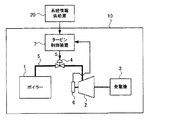
図2は、実施例1に係るタービン制御装置を備える発電プラントの概略ブロック構成図である。なお、図2には、説明の便宜上、タービン制御装置と関連する構成部のみを示す。また、本実施例では、発電プラントが火力発電プラントである例を説明する。
[Configuration and operation of power plant]
(1) Configuration FIG. 2 is a schematic block configuration diagram of a power plant including the turbine control device according to the first embodiment. FIG. 2 shows only components related to the turbine control device for convenience of explanation. Moreover, a present Example demonstrates the example whose power plant is a thermal power plant.
発電プラント10は、ボイラー1と、蒸気タービン2と、発電機3と、加減弁4と、配管5と、速度センサ6と、タービン制御装置7とを備える。
The
ボイラー1は、配管5を介して蒸気タービン2に接続され、配管5の途中には、加減弁4が設けられる。蒸気タービン2のタービン軸は、発電機3の回転軸に接続され、蒸気タービン2は発電機3に直結される。また、蒸気タービン2の回転速度を検出するための速度センサ6は、蒸気タービン2に取り付けられる。
The
タービン制御装置7は、速度センサ6に電気的に接続され、蒸気タービン2の回転速度を常時検出する。また、タービン制御装置7は、加減弁4と油圧を介して接続され、加減弁4の開度を制御して、ボイラー1から蒸気タービン2に流入する蒸気流量を調節する。
The
なお、図2には示さないが、発電プラント10(発電機3)は、送電線を介して他の各種発電システムに接続され、これにより、系統が構築される。また、発電プラント10(タービン制御装置7)は、例えばネットワーク等の通信網を介して、系統情報供給源20と接続され、発電プラント10が含まれる系統の運転状況に関する系統情報を系統情報供給源20から取得する。
Although not shown in FIG. 2, the power plant 10 (generator 3) is connected to other various power generation systems via a power transmission line, thereby constructing a system. The power plant 10 (turbine control device 7) is connected to the system
図3は、本実施例における系統情報供給源20の概略構成図である。本実施例では、系統情報供給源20は、発電プラント10が含まれる系統の運転状況に関する系統情報として、発電プラント10の外部施設(例えば中央給電所等)で算出されるリアルタイムの需給予測情報21を、タービン制御装置7に供給する。この際、本実施例では、系統情報供給源20は、リアルタイムの需給予測情報21(系統情報)を、VPN(Virtual Private Network)22、ルータ23及びプラントネットワーク24を介してタービン制御装置7に供給する。
FIG. 3 is a schematic configuration diagram of the system
(2)動作
上記構成の発電プラント10では、まず、ボイラー1は、例えば石油、石炭等の燃料を燃やして水を熱し、その際に発生する高温高圧の蒸気を、配管5を介して蒸気タービン2に供給する。次いで、蒸気タービン2は、ボイラー1から供給される高温高圧の蒸気により回転し、発電機3を駆動する。これにより、発電プラント10は、電力を発生し、該電力を系統に供給する。
(2) Operation In the
そして、本実施例では、蒸気タービン2を回転駆動する際、タービン制御装置7は、発電機3で発生する電力の系統周波数が所定の周波数(50Hz又は60Hz)になるように、加減弁4の開度を制御して蒸気タービン2の回転速度(回転数)を制御する。なお、この際、本実施例では、タービン制御装置7は、系統情報供給源20から取得した系統情報と、速度センサ6から取得される蒸気タービン2の回転速度の実測データとに基づいて、蒸気タービン2の調速負荷制御を行う。
In the present embodiment, when the
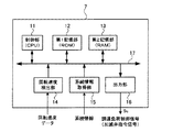
[タービン制御装置の構成]
図4は、本実施例のタービン制御装置7の内部構成(ハードウェア構成)図である。なお、図4には、説明を簡略化するため、蒸気タービン2の調速負荷制御に関連する構成部のみを示す。
[Configuration of turbine control unit]
FIG. 4 is an internal configuration (hardware configuration) diagram of the
タービン制御装置7は、制御部11(調速制御部)と、第1記憶部12と、第2記憶部13と、回転速度検出部14(回転速度取得部)と、系統情報取得部15と、出力部16とを備える。そして、これらの構成部は、バス17を介して、互いに電気的に接続される。
The
制御部11は、例えばCPU(Central Processing Unit)で構成され、演算処理装置及び制御装置として機能する。具体的には、制御部11は、例えば第1記憶部12や第2記憶部13等に記録された各種プログラムを用いて、タービン制御装置7内の動作全般又はその一部を制御する。それゆえ、後述する蒸気タービン2の調速負荷制御も制御部11により実行される。
The
第1記憶部12は、例えばROM(Read Only Memory)で構成され、制御部11が使用するプログラムや演算パラメータ等を記憶する。それゆえ、後述する蒸気タービン2の調速負荷制御処理で用いるプログラム(タービン制御プログラム)やその実行において必要となるパラメータ等は、第1記憶部12に記憶される。
The
第2記憶部13は、例えばRAM(Random Access Memory)で構成される。第2記憶部13では、例えば後述の蒸気タービン2の調速負荷制御処理時に、第1記憶部12に記憶された必要なプログラムや必要なパラメータ等が一時的に記憶及び展開される。
The
回転速度検出部14は、蒸気タービン2に取り付けられた速度センサ6に電気的に接続された入力インターフェースである。それゆえ、例えば、後述する蒸気タービン2の調速負荷制御時には、タービン制御装置7(制御部11)は、回転速度検出部14を介して、速度センサ6で検出された回転速度データ(実回転速度)を検出する。
The rotational
系統情報取得部15は、系統情報供給源20から系統情報を取得するための入力インターフェースである。それゆえ、例えば、後述する蒸気タービン2の調速負荷制御時には、タービン制御装置7は、系統情報取得部15を介して、系統情報を取得する。
The system
出力部16は、後述する蒸気タービン2の調速負荷制御処理により生成された調速負荷制御信号Sv(加減弁指令信号)を加減弁4に出力するためのインターフェースである。それゆえ、後述する蒸気タービン2の調速負荷制御時には、タービン制御装置7は、出力部16を介して調速負荷制御信号Svを加減弁4に出力する。
The
[蒸気タービンの調速負荷制御手法]
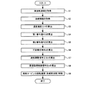
次に、本実施例のタービン制御装置7で行う蒸気タービン2の調速負荷制御手法(蒸気流量の制御手法)について、図5及び6を参照しながら説明する。
[Controlled load control method for steam turbine]
Next, a speed control load control method (steam flow rate control method) of the
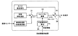
図5は、タービン制御装置7で実施される蒸気タービン2の調速負荷制御の制御アルゴリズムを示す図である。より具体的には、図5は、蒸気タービン2の調速制御処理時に、制御部11が生成する調速負荷制御信号Sv(加減弁指令信号)の演算アルゴリズムを示す図である。また、図6は、本実施例における蒸気タービン2の調速負荷制御の処理手順を示すフローチャートである。
FIG. 5 is a diagram illustrating a control algorithm for the controlled load control of the
なお、本実施例では、蒸気タービン2の調速負荷制御時に、制御部11は、第1記憶部12(ROM)に格納された蒸気タービン2の調速負荷制御プログラムを第2記憶部13(RAM)に展開する。そして、制御部11は、該調速負荷制御プログラムを用い、図5に示す演算アルゴリズムに従って以下に説明する各種演算処理を行い、蒸気タービン2の調速負荷制御処理を行う。すなわち、本実施例では、制御部11による蒸気タービン2の調速負荷制御処理を、ソフトウェアを用いて実行する。
In the present embodiment, during the controlled load control of the
また、本実施例では、上記比較例(図1)と同様に、蒸気タービン2の回転速度(蒸気タービン2に供給する蒸気流量)を、調定率に基づいて制御する。この際、調定率は、速度センサ6により検出された回転速度の実測データ(実回転速度)、及び、系統情報供給源20から供給される系統情報に基づいて、逐次調節される。なお、実回転速度及び系統情報は時間とともに変動するパラメータであるので、本実施例で算出される調定率(以下では、可変調定率Rvという)もまた時間とともに変化する。
In the present embodiment, similarly to the comparative example (FIG. 1), the rotational speed of the steam turbine 2 (the flow rate of steam supplied to the steam turbine 2) is controlled based on the settling rate. At this time, the settling rate is sequentially adjusted based on measured data (actual rotational speed) of the rotational speed detected by the
本実施例の蒸気タービン2の調速負荷制御手法では、まず、タービン制御装置7は、速度センサ6により検出された回転速度の実測データ(実回転速度)を、回転速度検出部14を介して取得する(ステップS1)。なお、上述のように、蒸気タービン2の回転数は系統周波数と等しくなるので、ステップS1では、実質、系統周波数の実測データに対応する情報を取得していることになる。
In the speed control load control method of the
次いで、タービン制御装置7は、系統情報供給源20から供給される系統情報を、系統情報取得部15を介して取得する(ステップS2)。この際、本実施例では、系統情報として、発電プラント10の外部施設で算出されるリアルタイムの需給予測情報21を、ネットワーク経由で取得する(図2及び3参照)。なお、本実施例では、ステップS2の処理をステップS1より先に実行してもよいし、ステップS2の処理をステップS1の処理と並行して実行してもよい。
Next, the
次いで、制御部11は、定格回転速度から実回転速度を減算して、速度偏差ΔVを算出する(ステップS3)。この算出処理は、図5中の減算ブロック31(減算部)で実行される演算処理に対応する。なお、定格回転速度の情報は、予め、タービン制御装置7内の第1記憶部12に記憶されており、蒸気タービン2の調速負荷制御時には、第1記憶部12から第2記憶部13に読み出されて使用される。
Next, the
次いで、制御部11は、取得した実回転速度に基づいて、系統周波数(実回転速度)の変動に対応する調定率の変動成分値(以下、第1寄与値R1という)を算出する(ステップS4)。また、制御部11は、取得した系統情報に基づいて、系統の運転状況の変動(負荷変動)に対応する調定率の変動成分値(以下、第2寄与値R2という)を算出する(ステップS5)。なお、本実施例では、ステップS5の処理をステップS4より先に実行してもよいし、ステップS5の処理をステップS4の処理と並行して実行してもよい。
Next, the
次いで、制御部11は、第1寄与値R1及び第2寄与値R2を用いて、可変調定率Rvを算出する(ステップS6)。ステップS4〜ステップS6の一連の算出処理は、図5中の可変調定率算出ブロック32(可変調定率算出部)で実行される演算処理に対応する。なお、ステップS4〜ステップS6で行う可変調定率Rvの算出処理については、後で、図面を参照しながら詳述する。
Next, the
次いで、制御部11は、ステップS3で算出した速度偏差ΔVに、ステップS6で算出した可変調定率Rvの逆数、すなわち、可変ゲインGv(=1/Rv)を乗算して、速度調整信号ΔSv(=Gv・ΔV)を算出する(ステップS7)。この算出処理は、図5中のゲイン乗算ブロック33(速度調整信号生成部)で実行される演算処理に対応する。
Next, the
次いで、制御部11は、速度調整信号ΔSv(=Gv・ΔV)にガバナ設定信号S0を加算して、調速負荷制御信号Sv(=S0+ΔSv)を算出する(ステップS8)。この算出処理は、図5中の加算ブロック34(加算部)で実行される演算処理に対応する。なお、ガバナ設定信号S0の情報は、予め、タービン制御装置7内の第1記憶部12に記憶されており、蒸気タービン2の調速負荷制御時には、第1記憶部12から第2記憶部13に読み出されて使用される。
Next, the
そして、制御部11は、ステップS8で生成した調速負荷制御信号Svから対応する加減弁開度を計算し、該加減弁開度を出力部16を介して加減弁4に出力し、該調速負荷制御信号Svに基づいて加減弁4の開度、すなわち、蒸気タービン2の回転速度(系統周波数)を制御する(ステップS9)。本実施例のタービン制御装置7では、このようにして、蒸気タービン2の調速負荷制御を行う。
Then, the
[可変調定率の算出及び調節手法]
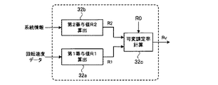
(1)可変調定率の算出手法
次に、図6中のステップS4〜ステップS6で行う可変調定率Rvの算出処理を、図7を参照しながらより詳細に説明する。なお、図7は、可変調定率Rvの算出アルゴリズムを示す図であり、図5中の可変調定率算出ブロック32で実行される演算処理のアルゴリズムを示す図である。
[Calculation and adjustment method of modulatable constant rate]
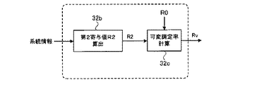
(1) Method for Calculating Modulatable Constant Rate Next, the process for calculating the modulatable constant rate Rv performed in steps S4 to S6 in FIG. 6 will be described in more detail with reference to FIG. FIG. 7 is a diagram showing an algorithm for calculating the modulatable constant rate Rv, and is a diagram showing an algorithm for the arithmetic processing executed by the modulatable constant
なお、図7中の第1寄与値R1の算出ブロック32a(第1寄与値算出部)における演算処理は、図6中のステップS4の処理に対応する。図7中の第2寄与値R2の算出ブロック32b(第2寄与値算出部)における演算処理は、図6中のステップS5の処理に対応する。また、図7中の可変調定率Rvの計算ブロック32c(可変調定率計算部)における演算処理は、図6中のステップS6の処理に対応する。
The calculation process in the first contribution value
本実施例では、図7に示すように、可変調定率Rvの計算ブロック32cにおける演算処理(ステップS6の処理)において、第1寄与値R1及び第2寄与値R2だけでなく、ベース調定率R0を用いて、可変調定率Rvを算出する。具体的には、可変調定率Rvの計算ブロック32cでは、ベース調定率R0から第1寄与値R1及び第2寄与値R2を減算して、可変調定率Rvを算出する(Rv=R0−R1−R2)。なお、ベース調定率R0の情報は、予め、タービン制御装置7内の第1記憶部12に記憶されており、蒸気タービン2の調速負荷制御時には、第1記憶部12から第2記憶部13に読み出されて使用される。
In the present embodiment, as shown in FIG. 7, in the calculation process (processing of step S6) in the
(2)可変調定率の調節手法
次に、本実施例における可変調定率Rvの調節手法について説明する。本実施例の可変調定率Rvの調節手法では、系統周波数fが急激に変化する場合及び/又はそれが予測される場合には、高ゲインの調速負荷制御(高速応答制御)が実行されるように、可変調定率Rvを小さくする。これにより、系統周波数fの変動に対する応答性を向上させる。
(2) Method for Adjusting Modulatable Constant Rate Next, a method for adjusting the modulatable constant rate Rv in this embodiment will be described. In the method of adjusting the modulatable constant rate Rv according to the present embodiment, when the system frequency f changes suddenly and / or when it is predicted, high-gain speed-control load control (high-speed response control) is executed. As described above, the modulatable constant rate Rv is reduced. Thereby, the responsiveness with respect to the fluctuation | variation of the system frequency f is improved.
一方、系統周波数fが緩やかに変化する場合(変化しない場合も含む)及び/又はそれが予測される場合には、低ゲインの調速負荷制御が実行されるように、可変調定率Rvを大きくする。これにより、発電プラント10の安定性を向上させる。なお、本実施例で、可変調定率Rvが、約3〜7%程度の範囲で変化するように、各寄与値の可変幅、及び、ベース調定率R0をそれぞれ適宜設定する。
On the other hand, when the system frequency f changes gently (including the case where it does not change) and / or when it is predicted, the adjustable constant rate Rv is increased so that the low-speed governing load control is executed. To do. Thereby, the stability of the
以下に、上述した本実施例の可変調定率Rvの調節手法を実現するための、第1寄与値R1の一算出例及び第2寄与値R2の一算出例を、図面を参照しながら具体的に説明する。 Hereinafter, an example of calculating the first contribution value R1 and an example of calculating the second contribution value R2 for realizing the above-described method for adjusting the modulatable constant rate Rv of this embodiment will be described in detail with reference to the drawings. Explained.
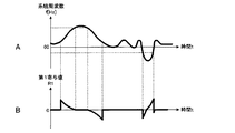
(3)第1寄与値R1の算出例
図8A及び8Bを参照しながら、第1寄与値R1の一算出例を説明する。図8Aは、系統周波数f(60Hz)の時間変動特性を示す図であり、図8Aに示す特性の横軸は時間tであり、縦軸は速度センサ6で検出される蒸気タービン2の実回転速度に対応する系統周波数fである。また、図8Bは、図8Aに示す系統周波数fの時間変動特性に対応する第1寄与値R1の時間変動特性を示す図であり、図8Bに示す特性の横軸は時間tであり、縦軸は第1寄与値R1である。
(3) Calculation Example of First Contribution Value R1 A calculation example of the first contribution value R1 will be described with reference to FIGS. 8A and 8B. FIG. 8A is a diagram showing the time variation characteristic of the system frequency f (60 Hz). The horizontal axis of the characteristic shown in FIG. 8A is time t, and the vertical axis is the actual rotation of the
図8A及び8Bに示す例では、系統周波数fの時間に対する変化率が大きくなった場合には、第1寄与値R1の絶対値を大きくし、系統周波数fの時間に対する変化率が小さくなった場合には、第1寄与値R1の絶対値を小さくする。また、系統周波数fが上昇する場合には、第1寄与値R1を正の値とし、系統周波数が低下する場合には第1寄与値R1を負の値とする。さらに、図8A及び8Bに示す例では、例えば、系統周波数fが微小変動する期間は、第1寄与値R1の値を0に設定する。 8A and 8B, when the rate of change of the system frequency f with respect to time increases, the absolute value of the first contribution value R1 is increased, and the rate of change of the system frequency f with respect to time decreases. The absolute value of the first contribution value R1 is reduced. Further, when the system frequency f increases, the first contribution value R1 is a positive value, and when the system frequency decreases, the first contribution value R1 is a negative value. Further, in the example shown in FIGS. 8A and 8B, for example, the value of the first contribution value R1 is set to 0 during a period in which the system frequency f slightly fluctuates.
図7中の第1寄与値R1の算出ブロック32aでは、このような系統周波数fと第1寄与値R1との関係に基づいて、第1寄与値R1が求められる。なお、図8A及び8Bに示すような系統周波数fと第1寄与値R1との関係は、例えば、過去の実績データに基づいて求められた両者間の関係式(経験式)を用いて規定してもよいし、両者間の対応テーブルを用いて規定してもよい。この場合、両者間の関係式又は対応テーブルは、第1記憶部12に格納される。また、系統周波数fと第1寄与値R1との関係、及び、第1寄与値R1の可変幅は、図8A及び8Bに示す例に限定されず、例えば、発電プラント10の性能(仕様)、系統の構成(他の発電システムの種別、構成など)等に応じて任意に変更することができる。
In the
なお、図8A及び8Bには、説明の便宜上、系統周波数fの時間変動特性と第1寄与値R1の時間変動特性との関係を用いて第1寄与値R1を算出する例を示した。しかしながら、上述のように、系統周波数fと蒸気タービン2の回転速度とは一対一で対応するので、速度センサ6で検出される蒸気タービン2の実回転速度の時間変動特性と第1寄与値R1の時間変動特性との関係も、図8A及び8Bに示す関係と同様になる。それゆえ、第1寄与値R1を算出する際には、系統周波数fの時間変動特性と第1寄与値R1の時間変動特性との関係の代わりに、速度センサ6で検出される蒸気タービン2の実回転速度の時間変動特性と第1寄与値R1の時間変動特性との関係を使用してもよい。
8A and 8B show an example in which the first contribution value R1 is calculated using the relationship between the time variation characteristic of the system frequency f and the time variation characteristic of the first contribution value R1 for convenience of explanation. However, as described above, the system frequency f and the rotational speed of the
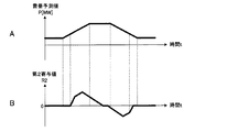
(4)第2寄与値R2の算出例
次に、図9A及び9Bを参照しながら、第2寄与値R2の一算出例を説明する。なお、図9Aは、需要予測値Pの時間変動特性(需要予測カーブ)を示す図であり、図9Aに示す特性の横軸は時間tであり、縦軸は需要予測値Pである。また、図9Bは、図9Aに示す需要予測値Pの時間変動特性に対応する第2寄与値R2の時間変動特性を示す図であり、図9Bに示す特性の横軸は時間tであり、縦軸は第2寄与値R2である。
(4) Calculation Example of Second Contribution Value R2 Next, a calculation example of the second contribution value R2 will be described with reference to FIGS. 9A and 9B. 9A is a diagram showing the time fluctuation characteristic (demand prediction curve) of the demand forecast value P. The horizontal axis of the characteristic shown in FIG. 9A is the time t, and the vertical axis is the demand forecast value P. 9B is a diagram showing the time variation characteristic of the second contribution value R2 corresponding to the time variation characteristic of the demand forecast value P shown in FIG. 9A, and the horizontal axis of the characteristic shown in FIG. 9B is time t. The vertical axis represents the second contribution value R2.
図9A及び9Bに示す例では、需要予測値Pの変化率が大きくなると予測される場合には、第2寄与値R2の絶対値を大きくする。一方、需要予測値Pの変化率が小さくなると予測される場合には、第2寄与値R2の絶対値を小さくする。また、本実施例では、需要予測値Pが上昇する場合には、第2寄与値R2を正の値とし、需要予測値Pが低下する場合には第2寄与値R2を負の値とする。 In the example shown in FIGS. 9A and 9B, when the change rate of the demand forecast value P is predicted to increase, the absolute value of the second contribution value R2 is increased. On the other hand, when it is predicted that the rate of change of the demand forecast value P will be small, the absolute value of the second contribution value R2 is made small. In the present embodiment, when the demand prediction value P increases, the second contribution value R2 is a positive value, and when the demand prediction value P decreases, the second contribution value R2 is a negative value. .
図7中の第2寄与値R2の算出ブロック32bでは、このような需要予測値Pと第2寄与値R2との関係に基づいて、第2寄与値R2が求められる。なお、図9A及び9Bに示すような需要予測値Pと第2寄与値R2との関係は、例えば、過去の実績データに基づいて求められた両者間の関係式(経験式)を用いて規定してもよいし、両者間の対応テーブルを用いて規定してもよい。この場合、両者間の関係式又は対応テーブルは、第1記憶部12に格納される。また、需要予測値Pと第2寄与値R2との関係、及び、第2寄与値R2の可変幅は、図9A及び9Bに示す例に限定されず、例えば、発電プラント10の性能(仕様)、系統の構成(他の発電システムの種別、構成など)等に応じて任意に変更することができる。
In the
上述のようにして、第1寄与値R1及び第2寄与値R2を算出した場合、系統周波数f及び/又は需要予測値Pの変化率が高くなると、第1寄与値R1及び/又は第2寄与値R2が大きくなる。この結果、可変調定率Rvが小さくなり、可変ゲインGvが大きくなる。すなわち、本実施例において、系統周波数fが急激に変化する場合及び/又はそれが予測される場合には、蒸気タービン2の制御は、高ゲインの調速負荷制御(高速応答制御)となる。
As described above, when the first contribution value R1 and the second contribution value R2 are calculated, if the rate of change of the system frequency f and / or the demand forecast value P increases, the first contribution value R1 and / or the second contribution The value R2 increases. As a result, the modulatable constant rate Rv decreases and the variable gain Gv increases. That is, in the present embodiment, when the system frequency f changes abruptly and / or when it is predicted, the control of the
一方、系統周波数f及び/又は需要予測値Pの変化率が低い場合には、第1寄与値R1及び/又は第2寄与値R2が小さくなる。この結果、可変調定率Rvが大きくなり、可変ゲインGvが小さくなる。すなわち、本実施例において、系統周波数fが緩やかに変化する場合及び/又はそれが予測される場合には、蒸気タービン2の制御は、低ゲインの調速負荷制御となる。
On the other hand, when the rate of change of the system frequency f and / or the demand forecast value P is low, the first contribution value R1 and / or the second contribution value R2 becomes small. As a result, the modulatable constant rate Rv increases and the variable gain Gv decreases. That is, in the present embodiment, when the system frequency f changes gently and / or when it is predicted, the control of the
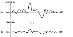
このような調速負荷制御手法を実行した場合に得られる系統周波数f(60Hz)の変動特性の一例(制御結果例)を図10A及び10Bを参照しながら説明する。なお、図10Aは、本実施例の調速負荷制御手法を採用しない場合における系統周波数fの時間変動特性の模式図であり、図10Bは、本実施例の調速負荷制御手法を採用した場合における系統周波数fの時間変動特性の模式図である。なお、各図の横軸は時間tであり、縦軸は系統周波数fである。 An example (control result example) of fluctuation characteristics of the system frequency f (60 Hz) obtained when such a speed control load control method is executed will be described with reference to FIGS. 10A and 10B. 10A is a schematic diagram of the time variation characteristics of the system frequency f when the speed control load control method according to the present embodiment is not employed, and FIG. 10B illustrates a case where the speed control load control method according to the present embodiment is employed. It is a schematic diagram of the time fluctuation characteristic of the system frequency f in FIG. In each figure, the horizontal axis represents time t, and the vertical axis represents system frequency f.
図10A及び10Bに示すように、本実施例の調速負荷制御手法を採用した場合には、系統周波数fが急激に変化する時間帯において、系統周波数fの変動を大きく抑制することができる。また、本実施例では、系統周波数fが緩やかに変化する時間帯においても、系統周波数fの変動をより小さくすることができ、発電プラント10の安定性を向上させることもできる。
As shown in FIGS. 10A and 10B, when the speed control load control method of the present embodiment is employed, fluctuations in the system frequency f can be greatly suppressed in a time zone in which the system frequency f changes rapidly. Further, in the present embodiment, the fluctuation of the system frequency f can be further reduced and the stability of the
[各種効果]
上述のように、本実施例の調速負荷制御手法では、系統情報(需要予測値P)に基づいて調定率を適宜調節しながら蒸気タービン2の調速負荷制御を行う。それゆえ、本実施例では、負荷運転中(定格回転速度近傍)であっても、系統の運転状況(負荷の変動状況)に応じて柔軟な系統周波数の調整(安定制御)が可能になる。なお、本実施例では、系統情報として、予測データを用いるので、将来の系統の運転状況を考慮して調速負荷制御を行うことができるので、より一層、柔軟な系統周波数の安定制御が可能になる。
[Effects]
As described above, in the speed control load control method of the present embodiment, the speed control load control of the
また、本実施例では、系統の運転状況に応じて、調速負荷制御の応答性能を適宜変化させることができる。それゆえ、上述した比較例で想定される各種課題を解決することができる。具体的には、プラントの安定性を優先し、調速負荷制御の応答性能を下げて発電プラント10の設備の長寿命化、燃焼の安定化を実現することができる。さらに、本実施例では、系統情報(需要予測値P)を用いて調速負荷制御を行うので、例えば、太陽光発電、風力発電などの天候等により供給電力量が大きく変動する発電システムが多く繋がる系統においても、系統周波数の安定性を向上させることができる。
In the present embodiment, the response performance of the speed control load control can be appropriately changed according to the operating state of the system. Therefore, various problems assumed in the comparative example described above can be solved. Specifically, priority is given to the stability of the plant, and the response performance of the speed control load control can be lowered, so that the equipment life of the
次に、実施例2に係るタービン制御装置及びそのタービン制御手法について説明する。なお、本実施例では、上記実施例1の蒸気タービンの調速負荷制御手法(制御アルゴリズム)とは異なる調速負荷制御手法(制御アルゴリズム)を用いる。しかしながら、発電プラントの構成、及び、タービン制御装置の構成は、上記実施例1のそれら(図2及び4)と同様である。それゆえ、ここでは、蒸気タービンの調速負荷制御手法についてのみ、図11及び12を参照しながら説明する。 Next, a turbine control device and a turbine control method according to the second embodiment will be described. In this embodiment, a speed control load control method (control algorithm) different from the speed control load control method (control algorithm) of the steam turbine of the first embodiment is used. However, the configuration of the power plant and the configuration of the turbine control device are the same as those of the first embodiment (FIGS. 2 and 4). Therefore, here, only the governing load control method of the steam turbine will be described with reference to FIGS.
図11は、本実施例における蒸気タービンの調速負荷制御の制御アルゴリズムを示す図である。また、図12は、本実施例における可変調定率Rvの算出アルゴリズムを示す図であり、図11中の可変調定率算出ブロック35で実行される演算処理のアルゴリズムを示す図である。なお、図11及び12に示す本実施例の調速負荷制御の制御アルゴリズムにおいて、上記実施例1(図5及び7)の調速負荷制御の制御アルゴリズムと同様の構成には、同じ符号を付して示す。
FIG. 11 is a diagram showing a control algorithm for the speed control load control of the steam turbine in the present embodiment. FIG. 12 is a diagram showing a calculation algorithm of the modulatable constant rate Rv in the present embodiment, and is a diagram showing an algorithm of arithmetic processing executed by the modulatable constant
図11と図5との比較、並びに、図12と図7との比較から明らかなように、本実施例では、可変調定率Rvを系統情報のみに基づいて調節する(変化させる)。すなわち、本実施例では、調定率の変動成分値としては、系統情報に基づいて算出される第2寄与値R2のみを用い、実回転速度(系統周波数)の変動に対応する第1寄与値R1を使用しない。 As is clear from the comparison between FIG. 11 and FIG. 5 and the comparison between FIG. 12 and FIG. 7, in this embodiment, the modulatable constant rate Rv is adjusted (changed) based only on the system information. That is, in this embodiment, only the second contribution value R2 calculated based on the system information is used as the fluctuation component value of the settling rate, and the first contribution value R1 corresponding to the fluctuation of the actual rotational speed (system frequency) is used. Do not use.
それゆえ、本実施例の調速負荷制御手法では、図6中のステップS4の処理(実回転速度に基づいて第1寄与値R1を算出する処理)は省略される。そして、本実施例では、第1寄与値R1を算出しないこと以外は、上記実施例1と同様にして、可変調定率Rvを算出して、蒸気タービンの調速負荷制御を行う。 Therefore, in the speed control load control method of the present embodiment, the process of step S4 in FIG. 6 (the process of calculating the first contribution value R1 based on the actual rotation speed) is omitted. In this embodiment, except that the first contribution value R1 is not calculated, the modulatable constant rate Rv is calculated in the same manner as in the first embodiment, and the regulated load control of the steam turbine is performed.
上述のように、本実施例の調速負荷制御手法においても、系統情報に基づいて調定率を適宜調節しながら蒸気タービンの調速負荷制御を行うので、上記実施例1と同様の各種効果が得られる。なお、上記実施例1では、系統周波数fの変動に対応する第1寄与値R1も考慮して可変調定率Rvを算出するので、系統周波数fの急激な変動に対する応答性の観点では、実施例1の調速負荷制御手法の方が、実施例2のそれより有利である。
As described above, also in the speed control load control method of the present embodiment, the speed control load control of the steam turbine is performed while appropriately adjusting the settling rate based on the system information. Therefore, various effects similar to those of the first embodiment are obtained. can get. In the first embodiment, since the modulatable constant rate Rv is calculated in consideration of the first contribution value R1 corresponding to the fluctuation of the system frequency f, from the viewpoint of responsiveness to a sudden fluctuation of the system frequency f, The speed regulating
[各種変形例]
本発明の構成は、上記各種実施例で説明した構成に限定されず、例えば、次のような各種変形例も含まれる。
[Variations]
The configuration of the present invention is not limited to the configuration described in the above various embodiments, and includes, for example, the following various modifications.
(1)変形例1
上記各種実施例では、タービン制御装置7の調速負荷制御処理における蒸気タービン2の回転速度の調整パラメータとして、調定率を用いる例を説明したが、本発明はこれに限定されない。例えば、蒸気タービン2の回転速度の調整パラメータとして、ゲインを用いてもよい。
(1)
In the above-described various embodiments, the example in which the regulation rate is used as the adjustment parameter of the rotational speed of the
この場合には、系統周波数fの実測値(蒸気タービン2の実回転速度)及び系統情報(需要予測値)、又は、系統情報のみに基づいて、可変ゲインGvを直接調節するような構成にする。具体的には、例えば図5中の可変調定率算出ブロック32を、ゲイン算出ブロックに変更する。また、この場合、ゲインは調定率の逆数であるので、図8A及び8Bに示すような系統周波数fと第1寄与値R1との関係、並びに、図9A及び9Bに示すような需要予測値Pと第2寄与値R2との関係も適宜変更する。
In this case, the variable gain Gv is directly adjusted based on the actual measurement value of the system frequency f (actual rotational speed of the steam turbine 2) and system information (demand predicted value) or only the system information. . Specifically, for example, the modulatable constant
(2)変形例2
上記各種実施例では、系統情報を外部からネットワークを介して取得する例を説明したが、本発明はこれに限定されない。例えば、予め、系統の需要予測カーブ等の系統情報が、タービン制御装置7及び/又は発電プラント10内のデータベースに蓄積されている場合には、タービン制御装置7及び/又は発電プラント10内のデータベースから直接、系統情報を取得してもよい。また、この場合、タービン制御装置7の構成を、タービン制御装置7及び/又は発電プラント10内のデータベースから現状に適した系統情報をオペレータにより適宜選択できるような構成にしてもよい。
(2)
In the various embodiments described above, examples have been described in which system information is acquired from the outside via a network, but the present invention is not limited to this. For example, when system information such as a system demand prediction curve is stored in a database in the
(3)変形例3
上記各種実施例では、系統情報として、需要予測データ(需要予測カーブ)を用いる例を説明したが、本発明はこれに限定されない。発電プラント10が接続されている系統の運転状況に関する情報であれば、任意の情報を系統情報として用いることができる。
(3)
In the various embodiments described above, an example in which demand forecast data (demand forecast curve) is used as system information has been described, but the present invention is not limited to this. Any information can be used as the system information as long as the information is related to the operation status of the system to which the
例えば、発電プラント10が属する系統に太陽光等の自然エネルギーを利用した発電システムが繋がれている場合には、気象情報(気象予測情報も含む)も系統情報として用いることができる。この場合、気象情報を、上述した需要予測データとは別個の系統情報(第2の系統情報)として用いてもよいし、需要予測データの代わりに用いてもよい。
For example, when a power generation system using natural energy such as sunlight is connected to the system to which the
前者の場合には、互いに種類の異なる複数の系統情報が、蒸気タービン2の調速負荷制御に用いられる。それゆえ、この場合には、気象情報等の第2の系統情報に対応する調定率の変動成分値(第3寄与値)が別途設けられ、第2の系統情報とそれに対応する第3寄与値との対応関係を示すデータを用いて、第3寄与値が求められる。
In the former case, a plurality of pieces of system information of different types are used for the speed control load control of the
(4)変形例4
上記各種実施例では、タービン制御装置7の調速負荷制御処理をソフトウェアで実現する例を説明したが、本発明はこれに限定されない。例えば、図5に示す調速負荷制御の制御アルゴリズムを構成する各種ブロックのうち、可変調定率算出ブロック32以外のブロックの全て又は一部をハードウェアで構成してもよい。
(4) Modification 4
In the various embodiments described above, the example in which the speed control load control process of the
(5)変形例5
上記各種実施例では、常時、本発明の調速負荷制御処理を実行する例を説明したが、本発明はこれに限定されない。例えば、系統周波数fが微小変動する期間は上述した調速負荷制御処理を実行しない構成(不感帯を設ける構成)にしてもよい。
(5)
In the various embodiments described above, the example in which the regulated load control process of the present invention is always executed has been described, but the present invention is not limited to this. For example, a configuration in which the above-described governing load control process is not executed during a period in which the system frequency f slightly fluctuates (a configuration in which a dead zone is provided) may be employed.
(6)変形例6
上記各種実施例では、タービン制御プログラム(調速負荷制御プログラム)が、予め、タービン制御装置7の第1記憶部12に実装(記憶)されている例を説明したが、本発明はこれに限定されない。外部から別途、タービン制御装置7にタービン制御プログラムを実装して上記調速負荷制御処理を実行する構成にしてもよい。この場合、タービン制御プログラムを、光ディスクや半導体メモリなどの媒体から配布する構成にしてもよいし、インターネットなどの通信網を介してダウンロードする構成にしてもよい。
(6)
In the various embodiments described above, an example in which the turbine control program (regulatory load control program) is mounted (stored) in the
(7)変形例7
上記各種実施例では、上述したタービン制御装置における調速負荷制御手法を火力発電プラントに適用する例を説明したが、本発明はこれに限定されない。流体の流量を調整して、タービンの回転速度を安定制御する必要がある発電プラントであれば、任意の発電プラントに適用可能である。例えば、蒸気タービンだけでなくガスタービンを用いた発電プラントにも上述した本発明の調速負荷制御手法を適用することができる。
(7)
In the various embodiments described above, the example in which the speed control load control method in the turbine control device described above is applied to a thermal power plant, but the present invention is not limited to this. Any power plant that adjusts the flow rate of fluid and needs to stably control the rotational speed of the turbine can be applied to any power plant. For example, the controlled load control method of the present invention described above can be applied not only to a steam turbine but also to a power plant using a gas turbine.
以上、本発明の各種実施例及び各種変形例に係るタービン制御装置及びタービン制御方法を説明したが、本発明の技術的範囲は、特許請求の範囲の記載に基づいて定められるべきであり、上記各種実施例及び各種変形例に限定されない。 Although the turbine control device and the turbine control method according to various embodiments and various modifications of the present invention have been described above, the technical scope of the present invention should be determined based on the description of the claims. The present invention is not limited to various embodiments and various modifications.
1…ボイラー、2…蒸気タービン、3…発電機、4…加減弁、5…配管、6…速度センサ、7…タービン制御装置、10…発電プラント、11…制御部、12…第1記憶部、13…第2記憶部、14…回転速度検出部、15…系統情報取得部、16…出力部、17…バス、20…系統情報供給源、21…需給予測情報、22…VPN、23…ルータ、24…プラントネットワーク、31…減算ブロック、32,35…可変調定率算出ブロック、32a…第1寄与値の算出ブロック、32b…第2寄与値の算出ブロック、32c…可変調定率の計算ブロック、33…ゲイン乗算ブロック、34…加算ブロック
DESCRIPTION OF
Claims (7)
前記系統情報に基づいて、系統の運転状況の変動に対応する調定率の第1の変動成分値を算出し、前記発電プラント内のタービンの回転速度の調整パラメータとして、予め設定されたベース調定率と前記第1の変動成分値とから可変調定率を算出する調速制御部と、を備え、
前記調速制御部は、前記可変調定率を用いて前記タービンの回転速度を調整する
タービン制御装置。 A grid information acquisition unit that acquires grid information regarding the operating status of the power grid to which the power plant is connected;
Based on the grid information, a first fluctuation component value of a settling rate corresponding to a fluctuation in the operating state of the grid is calculated, and a base settling rate set in advance as an adjustment parameter for the rotational speed of the turbine in the power plant and a governor control unit for calculating a tunable fixed rate from said first change component values,
The said speed control part is a turbine control apparatus which adjusts the rotational speed of the said turbine using the said modulation | alteration fixed constant .
前記調速制御部は、前記タービンの回転速度に基づいて、系統周波数の変動に対応する調定率の第2の変動成分値を算出し、前記調整パラメータとして、前記ベース調定率と前記第1の変動成分値と前記第2の変動成分値とから前記可変調定率を算出する
請求項1に記載のタービン制御装置。 Furthermore, a rotation speed acquisition unit that acquires information on the rotation speed of the turbine is provided,
The speed regulation control unit calculates a second fluctuation component value of a regulation rate corresponding to a system frequency fluctuation based on the rotational speed of the turbine, and uses the base regulation rate and the first regulation value as the adjustment parameter. The turbine control device according to claim 1, wherein the modulatable constant rate is calculated from a fluctuation component value and the second fluctuation component value .
請求項1又は2に記載のタービン制御装置。 The turbine control device according to claim 1, wherein the system information includes demand prediction data of the power system.
請求項2に記載のタービン制御装置。The turbine control device according to claim 2.
請求項3に記載のタービン制御装置。The turbine control device according to claim 3.
前記系統情報に基づいて、系統の運転状況の変動に対応する調定率の第1の変動成分値を算出することと、
前記発電プラント内のタービンの回転速度の調整パラメータとして、予め設定されたベース調定率と前記第1の変動成分値とから可変調定率を算出することと、
前記可変調定率を用いて前記タービンの回転速度を調整すること
を含むタービン制御方法。 Obtaining grid information about the operating status of the power system to which the power plant is connected,
Calculating a first fluctuation component value of a settling rate corresponding to fluctuations in the operating status of the grid based on the grid information;
Calculating a adjustable modulation rate from a preset base adjustment rate and the first fluctuation component value as an adjustment parameter of the rotational speed of the turbine in the power plant ;
A turbine control method comprising adjusting a rotational speed of the turbine using the modulatable constant rate .
前記系統情報に基づいて、系統の運転状況の変動に対応する調定率の第1の変動成分値を算出する処理と、
前記発電プラント内のタービンの回転速度の調整パラメータとして、予め設定されたベース調定率と前記第1の変動成分値とから可変調定率を算出する処理と、
前記可変調定率を用いて前記タービンの回転速度を調整する処理と
をタービン制御装置に実装して実行させるタービン制御プログラム。 A process of acquiring grid information regarding the operating status of the power grid to which the power plant is connected;
Based on the system information, a process of calculating a first variation component value of a settling rate corresponding to a variation in the operating status of the system,
As a parameter for adjusting the rotational speed of the turbine in the power plant, a process for calculating a modulatable constant rate from a preset base settling rate and the first fluctuation component value ;
The turbine control program which mounts and performs the process which adjusts the rotational speed of the said turbine using the said modulation | alteration constant ratio in a turbine control apparatus.
Priority Applications (3)
| Application Number | Priority Date | Filing Date | Title |
|---|---|---|---|
| JP2012207843A JP5730833B2 (en) | 2012-09-21 | 2012-09-21 | Turbine control device, turbine control method, and turbine control program |
| KR1020130094139A KR101595619B1 (en) | 2012-09-21 | 2013-08-08 | Turbine control device, turbine control method, and recording medium storing turbine control program |
| CN201310345052.8A CN103670537B (en) | 2012-09-21 | 2013-08-09 | turbine control device and turbine control method |
Applications Claiming Priority (1)
| Application Number | Priority Date | Filing Date | Title |
|---|---|---|---|
| JP2012207843A JP5730833B2 (en) | 2012-09-21 | 2012-09-21 | Turbine control device, turbine control method, and turbine control program |
Publications (2)
| Publication Number | Publication Date |
|---|---|
| JP2014062491A JP2014062491A (en) | 2014-04-10 |
| JP5730833B2 true JP5730833B2 (en) | 2015-06-10 |
Family
ID=50309218
Family Applications (1)
| Application Number | Title | Priority Date | Filing Date |
|---|---|---|---|
| JP2012207843A Active JP5730833B2 (en) | 2012-09-21 | 2012-09-21 | Turbine control device, turbine control method, and turbine control program |
Country Status (3)
| Country | Link |
|---|---|
| JP (1) | JP5730833B2 (en) |
| KR (1) | KR101595619B1 (en) |
| CN (1) | CN103670537B (en) |
Families Citing this family (3)
| Publication number | Priority date | Publication date | Assignee | Title |
|---|---|---|---|---|
| JP5897630B2 (en) | 2014-03-25 | 2016-03-30 | Dmg森精機株式会社 | Adjustment method of engine combustion chamber volume |
| KR102488689B1 (en) | 2020-08-14 | 2023-01-12 | 가천대학교 산학협력단 | Frequency Smoothing Control System and Method for electrical power system using a Synchronous Generators in association with Back-to-Back Convertors |
| JP2024075429A (en) * | 2022-11-22 | 2024-06-03 | 株式会社日立製作所 | Power generation turbine control system and method |
Family Cites Families (22)
| Publication number | Priority date | Publication date | Assignee | Title |
|---|---|---|---|---|
| JPS5297303U (en) * | 1976-01-19 | 1977-07-21 | ||
| JPS53110703A (en) * | 1977-03-09 | 1978-09-27 | Hitachi Ltd | Load control system |
| JPS5487319A (en) * | 1977-12-23 | 1979-07-11 | Nissan Motor Co Ltd | Fuel control equipment of gas turbine |
| JPS5725197A (en) * | 1980-07-23 | 1982-02-09 | Hitachi Ltd | Forecast follow-up controlling system for thermal power plant |
| JPH0814241B2 (en) * | 1988-08-10 | 1996-02-14 | 三菱重工業株式会社 | Turbine controller |
| JPH05340204A (en) | 1992-06-08 | 1993-12-21 | Toshiba Corp | Turbine controller |
| JPH0726906A (en) * | 1993-07-09 | 1995-01-27 | Toshiba Corp | Turbine starter |
| JPH08177409A (en) * | 1994-12-27 | 1996-07-09 | Toshiba Corp | Steam turbine plant |
| JPH10127099A (en) * | 1996-10-23 | 1998-05-15 | Toshiba Corp | Turbine control device |
| JPH11223302A (en) * | 1998-02-10 | 1999-08-17 | Babcock Hitachi Kk | Automatic control device and method of power generating plant |
| JP3361053B2 (en) * | 1998-05-14 | 2003-01-07 | 株式会社日立製作所 | Power plant load control device |
| JP2001082105A (en) * | 1999-09-17 | 2001-03-27 | Hitachi Ltd | Steam turbine inclination adjustment rate control method and apparatus |
| JP2003013744A (en) | 2001-06-29 | 2003-01-15 | Ebara Corp | Gas turbine controller, cogeneration system |
| JP2004027890A (en) * | 2002-06-24 | 2004-01-29 | Toshiba Corp | Load control device for multi-shaft combined cycle power plant |
| AU2003250280A1 (en) * | 2002-07-04 | 2004-01-23 | All-Russian Research Institute Of Automatics | Method and device for regulating the rotational speed of a turbine connected to an electric power supply mains by means of a generator |
| US7116010B2 (en) * | 2002-09-17 | 2006-10-03 | Wisconsin Alumni Research Foundation | Control of small distributed energy resources |
| JP4285068B2 (en) | 2003-05-08 | 2009-06-24 | 株式会社日立製作所 | Power plant, power plant control method, and plant control information providing method |
| US7274111B2 (en) * | 2005-12-09 | 2007-09-25 | General Electric Company | Methods and apparatus for electric power grid frequency stabilization |
| CN201372814Y (en) * | 2009-03-20 | 2009-12-30 | 宝钢集团新疆八一钢铁有限公司 | Steam turbine soft speed regulator |
| CN102146812B (en) * | 2010-02-09 | 2014-04-02 | 浙江省电力公司 | Actual-measurement modeling method for prime mover and speed governor thereof of electric power system |
| US8768529B2 (en) * | 2010-07-20 | 2014-07-01 | General Electric Company | Grid frequency rate limiting system |
| CN102562180B (en) * | 2011-11-29 | 2014-10-22 | 中国神华能源股份有限公司 | Control method and system for speed regulation valve of steam turbine |
-
2012
- 2012-09-21 JP JP2012207843A patent/JP5730833B2/en active Active
-
2013
- 2013-08-08 KR KR1020130094139A patent/KR101595619B1/en active Active
- 2013-08-09 CN CN201310345052.8A patent/CN103670537B/en active Active
Also Published As
| Publication number | Publication date |
|---|---|
| CN103670537B (en) | 2016-08-24 |
| JP2014062491A (en) | 2014-04-10 |
| CN103670537A (en) | 2014-03-26 |
| KR101595619B1 (en) | 2016-02-18 |
| KR20140038874A (en) | 2014-03-31 |
Similar Documents
| Publication | Publication Date | Title |
|---|---|---|
| US9745958B2 (en) | Method and system for managing loads on a wind turbine | |
| JP5177382B2 (en) | Power system frequency controller using natural energy power generation equipment | |
| EP3068007B1 (en) | System and method for improved reactive power speed-of-response for a wind farm | |
| JP6812107B2 (en) | Compensation systems and methods for gas turbine proportional droop governors | |
| EP3317520B1 (en) | Control method and system for protection of wind turbines | |
| Kishor et al. | A review on hydropower plant models and control | |
| JP5102957B2 (en) | Wind turbine generator control method and control system | |
| KR101213002B1 (en) | Control device of wind turbine generator and control method thereof | |
| US10318666B2 (en) | Simulation of a maximum power output of a wind turbine | |
| CN107577148B (en) | Primary frequency modulation optimization control system and method for thermal power generating unit based on water supply compensation | |
| EP3531527B1 (en) | Power control method and device for wind turbine generator system | |
| US20110080001A1 (en) | Method for controlling a wind turbine at high thermal loads | |
| CN107110119B (en) | Over-rating operation control of wind turbine generator | |
| CN107850048B (en) | Method and system for generating a wind turbine control arrangement | |
| JP5730833B2 (en) | Turbine control device, turbine control method, and turbine control program | |
| Gonzalez Silva et al. | Wind tunnel testing of wind turbine and wind farm control strategies for active power regulation | |
| JP2015090145A (en) | Wind power generator, method for restricting fluctuation of wind power generator and program for restricting fluctuation of wind power generator | |
| CN101933211A (en) | Method for operating a wind energy installation | |
| Yin et al. | Modeling and loading compensation of a rotary valve-controlled pitch system for wind turbines | |
| CN114243728A (en) | Type-II Type double-fed variable-speed pump storage unit | |
| KR20250023083A (en) | System and Method for controlling power generator to enhance frequency control performance | |
| Tuaimah et al. | Steam turbine governor design based on pole placement technique | |
| Hosseini-Sani et al. | Dmc versus gain scheduled pi controller for pitch regulation of 100 kw wind turbine | |
| CN112832873A (en) | Control method and control system of constant pressure unit participating in power grid frequency regulation | |
| Li et al. | Inverse-System Based Hybrid Control for Wind Turbines in the Near-Rated Wind Speed |
Legal Events
| Date | Code | Title | Description |
|---|---|---|---|
| A621 | Written request for application examination |
Free format text: JAPANESE INTERMEDIATE CODE: A621 Effective date: 20140725 |
|
| A977 | Report on retrieval |
Free format text: JAPANESE INTERMEDIATE CODE: A971007 Effective date: 20141218 |
|
| A131 | Notification of reasons for refusal |
Free format text: JAPANESE INTERMEDIATE CODE: A131 Effective date: 20141224 |
|
| A521 | Written amendment |
Free format text: JAPANESE INTERMEDIATE CODE: A523 Effective date: 20150213 |
|
| TRDD | Decision of grant or rejection written | ||
| A01 | Written decision to grant a patent or to grant a registration (utility model) |
Free format text: JAPANESE INTERMEDIATE CODE: A01 Effective date: 20150331 |
|
| A61 | First payment of annual fees (during grant procedure) |
Free format text: JAPANESE INTERMEDIATE CODE: A61 Effective date: 20150408 |
|
| R150 | Certificate of patent or registration of utility model |
Ref document number: 5730833 Country of ref document: JP Free format text: JAPANESE INTERMEDIATE CODE: R150 |