JP5730373B2 - Image reading device - Google Patents

Image reading device Download PDF

Info

Publication number
JP5730373B2
JP5730373B2 JP2013222674A JP2013222674A JP5730373B2 JP 5730373 B2 JP5730373 B2 JP 5730373B2 JP 2013222674 A JP2013222674 A JP 2013222674A JP 2013222674 A JP2013222674 A JP 2013222674A JP 5730373 B2 JP5730373 B2 JP 5730373B2
Authority
JP
Japan
Prior art keywords
document
unit
sound
jam
signal
Prior art date
Legal status (The legal status is an assumption and is not a legal conclusion. Google has not performed a legal analysis and makes no representation as to the accuracy of the status listed.)
Active
Application number
JP2013222674A
Other languages
Japanese (ja)
Other versions
JP2014043350A5 (en
JP2014043350A (en
Inventor
貴之 海
貴之 海
雅信 本江
雅信 本江
Current Assignee (The listed assignees may be inaccurate. Google has not performed a legal analysis and makes no representation or warranty as to the accuracy of the list.)
PFU Ltd
Original Assignee
PFU Ltd
Priority date (The priority date is an assumption and is not a legal conclusion. Google has not performed a legal analysis and makes no representation as to the accuracy of the date listed.)
Filing date
Publication date
Application filed by PFU Ltd filed Critical PFU Ltd
Priority to JP2013222674A priority Critical patent/JP5730373B2/en
Publication of JP2014043350A publication Critical patent/JP2014043350A/en
Publication of JP2014043350A5 publication Critical patent/JP2014043350A5/ja
Application granted granted Critical
Publication of JP5730373B2 publication Critical patent/JP5730373B2/en
Active legal-status Critical Current
Anticipated expiration legal-status Critical

Links

Images

Landscapes

  • Facsimile Scanning Arrangements (AREA)
  • Controlling Sheets Or Webs (AREA)
  • Facsimiles In General (AREA)

Description

本発明は、画像読取装置に関し、特に、原稿が搬送中に発生する音に基づいてジャムが発生したか否かを判定する画像読取装置に関する。   The present invention relates to an image reading apparatus, and more particularly to an image reading apparatus that determines whether or not a jam has occurred based on sound generated while a document is being conveyed.

画像読取装置では、原稿が搬送路を移動する際にジャム(紙詰まり)が発生する場合がある。一般に、画像読取装置は、原稿の搬送を開始してから所定時間内に搬送路内の所定位置まで原稿が搬送されたか否かによりジャムが発生したか否かを判定し、ジャムが発生したときには装置の動作を停止する機能を備える。   In the image reading apparatus, a jam (paper jam) may occur when the document moves on the conveyance path. Generally, an image reading apparatus determines whether or not a jam has occurred depending on whether or not a document has been transported to a predetermined position in a transport path within a predetermined time after the start of document transport. A function for stopping the operation of the apparatus is provided.

一方、ジャムが発生すると搬送路で大きな音が発生するため、画像読取装置は、搬送路で発生する音に基づいてジャムが発生したか否かを判定することにより、所定時間の経過を待たずにジャムの発生を検知できる可能性がある。   On the other hand, when a jam occurs, a loud sound is generated in the conveyance path. Therefore, the image reading apparatus determines whether or not a jam has occurred based on the sound generated in the conveyance path, and thus does not wait for a predetermined time. It may be possible to detect the occurrence of jam.

搬送路で発生する音を電気信号に変換し、基準レベルを超えている時間が基準値を超えた場合にジャムが発生したと判定する複写機のジャム検出装置が開示されている(特許文献1を参照)。   A jam detection device for a copying machine that converts a sound generated in a conveyance path into an electric signal and determines that a jam has occurred when a time exceeding a reference level exceeds a reference value is disclosed (Patent Document 1). See).

特開昭57−169767号公報JP 57-169767 A

しかしながら、ジャムが発生したときに音が発生する位置はジャムの種類により異なるので、ジャムの種類によって最適な集音位置で集音できることが望まれる。   However, the position where the sound is generated when a jam occurs differs depending on the type of jam. Therefore, it is desirable that the sound can be collected at an optimum sound collection position depending on the type of jam.

本発明の目的は、複数種類のジャムについて、ジャムが発生したときに発生する音を良好に集音することが可能な画像読取装置を提供することにある。   An object of the present invention is to provide an image reading apparatus capable of collecting sound generated when a jam occurs for a plurality of types of jams.

本発明の一側面に係る画像読取装置は、分離部と、原稿から画像を読取る画像読取部と、分離部で分離された原稿を画像読取部へ搬送する搬送部と、分離部から画像読取部へ搬送される原稿の端部側に設けられた搬送路側壁と、集音部が分離部と搬送部との間であって且つ搬送路側壁の近傍に設けられ、原稿が搬送中に発生する音に応じた音信号を出力する音信号出力部と、音信号に基づいて、ジャムが発生したか否かを判定するジャム判定部と、を有する。   An image reading apparatus according to an aspect of the present invention includes a separation unit, an image reading unit that reads an image from a document, a transport unit that transports a document separated by the separation unit to the image reading unit, and a separation unit to an image reading unit. The side wall of the transport path provided on the end side of the document transported to the side and the sound collecting unit are provided between the separation unit and the transport unit and in the vicinity of the side wall of the transport path, and are generated during transport of the document. A sound signal output unit that outputs a sound signal corresponding to the sound; and a jam determination unit that determines whether or not a jam has occurred based on the sound signal.

本発明によれば、分離部と搬送部との間であって且つ搬送路側壁の近傍に音信号出力部が設けられるため、原稿が傾いて搬送されてジャムが発生したとき、及び原稿がステイプルで綴じられてジャムが発生したときに発生する音を良好に集音することが可能となった。   According to the present invention, since the sound signal output unit is provided between the separation unit and the conveyance unit and in the vicinity of the side wall of the conveyance path, the jamming occurs when the document is inclined and conveyed, and the document is stapled. It is now possible to collect sound that is generated when jamming occurs.

画像読取装置100を示す斜視図である。1 is a perspective view showing an image reading apparatus 100. FIG. 画像読取装置100内部の搬送経路を説明するための図である。3 is a diagram for explaining a conveyance path inside the image reading apparatus 100. FIG. 上側筐体102を取り外した状態で下側から見た図である。It is the figure seen from the lower side in the state which removed the upper housing | casing 102. FIG. 画像読取装置100を上側筐体102を取り外して上側から見た図である。FIG. 3 is a view of the image reading apparatus 100 as viewed from above with the upper housing 102 removed. スキュージャムについて説明するための図である。It is a figure for demonstrating skew jam. ステイプルジャムについて説明するための図である。It is a figure for demonstrating a staple jam. 画像読取装置100の概略構成を示すブロック図である。1 is a block diagram illustrating a schematic configuration of an image reading apparatus 100. FIG. 画像読取装置100の全体処理の動作の例を示すフローチャートである。3 is a flowchart showing an example of the operation of the entire process of the image reading apparatus 100. 異常判定処理の動作の例を示すフローチャートである。It is a flowchart which shows the example of operation | movement of an abnormality determination process. 音ジャム判定処理の動作の例を示すフローチャートである。It is a flowchart which shows the example of operation | movement of a sound jam determination process. 第1マイクロフォン113aの配置位置を説明するための図である。It is a figure for demonstrating the arrangement position of the 1st microphone 113a. スキュージャム発生時の第1絶対値信号の例を示すグラフである。It is a graph which shows the example of the 1st absolute value signal at the time of skew jam occurrence. スキュージャム発生時の第1外形信号の例を示すグラフである。It is a graph which shows the example of the 1st outline signal at the time of skew jam occurrence. スキュージャム発生時の第1カウンタ値の例を示すグラフである。It is a graph which shows the example of the 1st counter value at the time of skew jam occurrence. ステイプルジャム発生時の第1絶対値信号の例を示すグラフである。It is a graph which shows the example of the 1st absolute value signal at the time of staple jam generation. ステイプルジャム発生時の第1外形信号の例を示すグラフである。It is a graph which shows the example of the 1st outline signal at the time of staple jam occurrence. ステイプルジャム発生時の第1カウンタ値の例を示すグラフである。It is a graph which shows the example of the 1st counter value at the time of staple jam occurrence. スキュージャム発生時の第1絶対値信号の例を示すグラフである。It is a graph which shows the example of the 1st absolute value signal at the time of skew jam occurrence. スキュージャム発生時の第1外形信号の例を示すグラフである。It is a graph which shows the example of the 1st outline signal at the time of skew jam occurrence. スキュージャム発生時の第1カウンタ値の例を示すグラフである。It is a graph which shows the example of the 1st counter value at the time of skew jam occurrence. ステイプルジャム発生時の第1絶対値信号の例を示すグラフである。It is a graph which shows the example of the 1st absolute value signal at the time of staple jam generation. ステイプルジャム発生時の第1外形信号の例を示すグラフである。It is a graph which shows the example of the 1st outline signal at the time of staple jam occurrence. ステイプルジャム発生時の第1カウンタ値の例を示すグラフである。It is a graph which shows the example of the 1st counter value at the time of staple jam occurrence. ステイプルジャム発生時の第1絶対値信号の例を示すグラフである。It is a graph which shows the example of the 1st absolute value signal at the time of staple jam generation. ステイプルジャム発生時の第1外形信号の例を示すグラフである。It is a graph which shows the example of the 1st outline signal at the time of staple jam occurrence. ステイプルジャム発生時の第1カウンタ値の例を示すグラフである。It is a graph which shows the example of the 1st counter value at the time of staple jam occurrence. スキュージャム発生時の第1絶対値信号の例を示すグラフである。It is a graph which shows the example of the 1st absolute value signal at the time of skew jam occurrence. スキュージャム発生時の第1外形信号の例を示すグラフである。It is a graph which shows the example of the 1st outline signal at the time of skew jam occurrence. スキュージャム発生時の第1カウンタ値の例を示すグラフである。It is a graph which shows the example of the 1st counter value at the time of skew jam occurrence. 位置ジャム判定処理の動作の例を示すフローチャートである。It is a flowchart which shows the example of operation | movement of a position jam determination process. 重送判定処理の動作の例を示すフローチャートである。It is a flowchart which shows the example of operation | movement of a double feed determination process. 超音波信号の特性について説明するための図である。It is a figure for demonstrating the characteristic of an ultrasonic signal.

以下、本発明の一側面に係る画像読取装置について図を参照しつつ説明する。但し、本発明の技術的範囲はそれらの実施の形態に限定されず、特許請求の範囲に記載された発明とその均等物に及ぶ点に留意されたい。   An image reading apparatus according to an aspect of the present invention will be described below with reference to the drawings. However, it should be noted that the technical scope of the present invention is not limited to these embodiments, but extends to the invention described in the claims and equivalents thereof.

図1は、イメージスキャナとして構成された画像読取装置100を示す斜視図である。   FIG. 1 is a perspective view showing an image reading apparatus 100 configured as an image scanner.

画像読取装置100は、下側筐体101、上側筐体102、原稿台103、排出台105及び操作ボタン106等を備える。   The image reading apparatus 100 includes a lower housing 101, an upper housing 102, a document table 103, a discharge table 105, operation buttons 106, and the like.

上側筐体102は、画像読取装置100の上面を覆う位置に配置され、原稿つまり時、画像読取装置100内部の清掃時等に開閉可能なようにヒンジにより下側筐体101に係合している。   The upper casing 102 is disposed at a position covering the upper surface of the image reading apparatus 100, and is engaged with the lower casing 101 by a hinge so that it can be opened and closed when a document, that is, when the inside of the image reading apparatus 100 is cleaned. Yes.

原稿台103は、原稿を載置可能に下側筐体101に係合している。原稿台103には、原稿の搬送方向と直行する方向A1、すなわち原稿の搬送方向に対して左右方向に移動可能なサイドガイド104a及び104bが設けられている。サイドガイド104a及び104bを原稿の幅に合わせて位置決めすることにより原稿の幅方向を規制することができる。   The document table 103 is engaged with the lower housing 101 so that a document can be placed thereon. The document table 103 is provided with side guides 104a and 104b that are movable in the left-right direction with respect to a direction A1 perpendicular to the document conveyance direction, that is, the document conveyance direction. By positioning the side guides 104a and 104b according to the width of the document, the width direction of the document can be regulated.

排出台105は、矢印A2で示す方向に回転可能なように、ヒンジにより下側筐体101に係合しており、図1のように開いている状態では、排出された原稿を保持することが可能となる。   The discharge table 105 is engaged with the lower casing 101 by a hinge so as to be rotatable in the direction indicated by the arrow A2, and holds the discharged document when it is open as shown in FIG. Is possible.

操作ボタン106は、上側筐体102の表面に配置され、押下されると、操作検出信号を生成して出力する。   The operation button 106 is disposed on the surface of the upper casing 102 and, when pressed, generates and outputs an operation detection signal.

図2は、画像読取装置100内部の搬送経路を説明するための図である。   FIG. 2 is a diagram for explaining a conveyance path inside the image reading apparatus 100.

画像読取装置100内部の搬送経路は、第1原稿検出部110、給紙ローラ111a、111b、リタードローラ112a、112b、第1マイクロフォン113a、第2マイクロフォン113b、第2原稿検出部114、超音波送信器115a、超音波受信器115b、第1搬送ローラ116a、116b、第1従動ローラ117a、117b、第3原稿検出部118、第1撮像部119a、第2撮像部119b、第2搬送ローラ120a、120b及び第2従動ローラ121a、121b等を有している。   The conveyance path inside the image reading apparatus 100 includes a first document detection unit 110, paper feed rollers 111a and 111b, retard rollers 112a and 112b, a first microphone 113a, a second microphone 113b, a second document detection unit 114, and ultrasonic transmission. 115a, ultrasonic receiver 115b, first conveyance rollers 116a and 116b, first driven rollers 117a and 117b, third document detection unit 118, first imaging unit 119a, second imaging unit 119b, second conveyance roller 120a, 120b and second driven rollers 121a and 121b.

以下では、給紙ローラ111a及び111bを総じて給紙ローラ111と称し、リタードローラ112a及び112bを総じてリタードローラ112と称し、第1搬送ローラ116a及び116bを総じて第1搬送ローラ116と称し、第1従動ローラ117a及び117bを総じて第1従動ローラ117と称し、第2搬送ローラ120a及び120bを総じて第2搬送ローラ120と称し、第2従動ローラ121a及び121bを総じて第2従動ローラ121と称する場合がある。   Hereinafter, the paper feed rollers 111a and 111b are collectively referred to as the paper feed roller 111, the retard rollers 112a and 112b are collectively referred to as the retard roller 112, the first transport rollers 116a and 116b are collectively referred to as the first transport roller 116, and the first The driven rollers 117a and 117b are generally referred to as a first driven roller 117, the second transport rollers 120a and 120b are generally referred to as a second transport roller 120, and the second driven rollers 121a and 121b are collectively referred to as a second driven roller 121. is there.

下側筐体101の上面は原稿の搬送路の下側ガイド107aを形成し、上側筐体102の下面は原稿の搬送路の上側ガイド107bを形成する。図2において矢印A3は原稿の搬送方向を示す。以下では、上流とは原稿の搬送方向A3の上流のことをいい、下流とは原稿の搬送方向A3の下流のことをいう。   The upper surface of the lower casing 101 forms a lower guide 107a of the document conveyance path, and the lower surface of the upper casing 102 forms an upper guide 107b of the document conveyance path. In FIG. 2, an arrow A3 indicates the document conveyance direction. Hereinafter, upstream means upstream in the document transport direction A3, and downstream means downstream in the document transport direction A3.

第1原稿検出部110は、給紙ローラ111及びリタードローラ112の上流側に配置される接触検出センサを有し、原稿台103に原稿が載置されているか否かを検出する。第1原稿検出部110は、原稿台103に原稿が載置されている状態と載置されていない状態とで信号値が変化する第1原稿検出信号を生成して出力する。   The first document detection unit 110 includes a contact detection sensor disposed on the upstream side of the paper feed roller 111 and the retard roller 112, and detects whether or not a document is placed on the document table 103. The first document detection unit 110 generates and outputs a first document detection signal whose signal value changes depending on whether the document is placed on the document table 103 or not.

第1マイクロフォン113a及び第2マイクロフォン113bは、それぞれ原稿が搬送中に発生する音を集音し、集音した音から生成したアナログの信号を出力する。第1マイクロフォン113a及び第2マイクロフォン113bは、給紙ローラ111及びリタードローラ112の下流側に、上側筐体102内部のフレーム108に固定されて配置される。原稿が搬送中に発生する音をより的確に第1マイクロフォン113a及び第2マイクロフォン113bが集音できるように、上側ガイド107bの第1マイクロフォン113a及び第2マイクロフォン113bに対向する位置にはそれぞれ穴109a及び109bが設けられている。以下では、第1マイクロフォン113a及び第2マイクロフォン113bを総じてマイクロフォン113と称する場合がある。   Each of the first microphone 113a and the second microphone 113b collects sound generated while the document is being conveyed, and outputs an analog signal generated from the collected sound. The first microphone 113 a and the second microphone 113 b are fixed to the frame 108 inside the upper housing 102 on the downstream side of the paper feed roller 111 and the retard roller 112. A hole 109a is provided in each of the positions of the upper guide 107b facing the first microphone 113a and the second microphone 113b so that the first microphone 113a and the second microphone 113b can collect the sound generated while the document is being conveyed more accurately. And 109b are provided. Hereinafter, the first microphone 113a and the second microphone 113b may be collectively referred to as the microphone 113.

第2原稿検出部114は、給紙ローラ111及びリタードローラ112の下流側、かつ第1搬送ローラ116及び第1従動ローラ117の上流側に配置される接触検出センサを有し、その位置に原稿が存在するか否かを検出する。第2原稿検出部114は、その位置に原稿が存在する状態と存在しない状態とで信号値が変化する第2原稿検出信号を生成して出力する。   The second document detection unit 114 includes a contact detection sensor disposed on the downstream side of the paper feed roller 111 and the retard roller 112 and on the upstream side of the first conveyance roller 116 and the first driven roller 117, and the document is located at that position. Whether or not exists is detected. The second document detection unit 114 generates and outputs a second document detection signal whose signal value changes depending on whether or not a document exists at that position.

超音波送信器115a及び超音波受信器115bは、超音波信号出力部の例であり、原稿の搬送路の近傍に、搬送路を挟んで対向するように配置される。超音波送信器115aは超音波を送信する。一方、超音波受信器115bは、超音波送信器115aにより送信され、原稿を通過した超音波を検出し、検出した超音波に応じた電気信号である超音波信号を生成して出力する。以下では、超音波送信器115a及び超音波受信器115bを総じて超音波センサ115と称する場合がある。   The ultrasonic transmitter 115a and the ultrasonic receiver 115b are examples of an ultrasonic signal output unit, and are arranged in the vicinity of the document conveyance path so as to face each other with the conveyance path interposed therebetween. The ultrasonic transmitter 115a transmits ultrasonic waves. On the other hand, the ultrasonic receiver 115b detects the ultrasonic wave transmitted by the ultrasonic transmitter 115a and passed through the document, and generates and outputs an ultrasonic signal that is an electrical signal corresponding to the detected ultrasonic wave. Hereinafter, the ultrasonic transmitter 115a and the ultrasonic receiver 115b may be collectively referred to as an ultrasonic sensor 115.

第3原稿検出部118は、第1搬送ローラ116及び第1従動ローラ117の下流側、かつ第1撮像部119a及び第2撮像部119bの上流側に配置される接触検出センサを有し、その位置に原稿が存在するか否かを検出する。第3原稿検出部118は、その位置に原稿が存在する状態と存在しない状態とで信号値が変化する第3原稿検出信号を生成して出力する。   The third document detection unit 118 includes a contact detection sensor disposed on the downstream side of the first conveyance roller 116 and the first driven roller 117 and on the upstream side of the first imaging unit 119a and the second imaging unit 119b. It detects whether or not a document exists at the position. Third document detection unit 118 generates and outputs a third document detection signal whose signal value changes depending on whether or not a document exists at that position.

第1撮像部119aは、主走査方向に直線状に配列されたCMOS(Complementary Metal Oxide Semiconductor)による撮像素子を備える等倍光学系タイプのCIS(Contact Image Sensor)を有する。このCISは、原稿の裏面から画像を読み取ってアナログの画像信号を生成して出力する。同様に、第2撮像部119bは、主走査方向に直線状に配列されたCMOSによる撮像素子を備える等倍光学系タイプのCISを有する。このCISは、原稿の表面から画像を読み取ってアナログの画像信号を生成して出力する。なお、第1撮像部119a及び第2撮像部119bを一方だけ配置し、原稿の片面だけを読み取るようにしてもよい。また、CISの代わりにCCD(Charge Coupled Device)による撮像素子を備える縮小光学系タイプの撮像センサを利用することもできる。以下では、第1撮像部119a及び第2撮像部119bを総じて撮像部119と称する場合がある。   The first image pickup unit 119a has a contact image sensor (CIS) of the same magnification optical system that includes image pickup elements of CMOS (Complementary Metal Oxide Semiconductor) arranged linearly in the main scanning direction. This CIS reads an image from the back side of a document, generates an analog image signal, and outputs it. Similarly, the second imaging unit 119b has an equal magnification optical system type CIS provided with CMOS imaging elements arranged linearly in the main scanning direction. This CIS reads an image from the surface of a document, generates an analog image signal, and outputs it. Note that only one of the first imaging unit 119a and the second imaging unit 119b may be arranged so that only one side of the document is read. Further, instead of CIS, a reduction optical system type image sensor provided with an image sensor by CCD (Charge Coupled Device) can be used. Hereinafter, the first imaging unit 119a and the second imaging unit 119b may be collectively referred to as an imaging unit 119.

原稿台103に載置された原稿は、給紙ローラ111が図2の矢印A4の方向に回転することによって、下側ガイド107aと上側ガイド107bの間を原稿搬送方向A3に向かって搬送される。リタードローラ112は、原稿搬送時、図2の矢印A5の方向に回転する。給紙ローラ111及びリタードローラ112の働きにより、原稿台103に複数の原稿が載置されている場合、原稿台103に載置されている原稿のうち給紙ローラ111と接触している原稿のみが分離されて、分離された原稿以外の原稿の搬送が制限される(重送の防止)ように動作する。給紙ローラ111及びリタードローラ112は、原稿の分離部として機能する。   The document placed on the document table 103 is transported in the document transport direction A3 between the lower guide 107a and the upper guide 107b as the paper feed roller 111 rotates in the direction of arrow A4 in FIG. . The retard roller 112 rotates in the direction of arrow A5 in FIG. When a plurality of documents are placed on the document table 103 by the functions of the paper feed roller 111 and the retard roller 112, only the documents that are in contact with the paper feed roller 111 among the documents placed on the document table 103. Are separated, and the conveyance of originals other than the separated originals is restricted (preventing double feeding). The paper feed roller 111 and the retard roller 112 function as a document separation unit.

原稿は、下側ガイド107aと上側ガイド107bによりガイドされながら、第1搬送ローラ116と第1従動ローラ117の間に送り込まれる。原稿は、第1搬送ローラ116が図2の矢印A6の方向に回転することによって、第1撮像部119aと第2撮像部119bの間に送り込まれる。第1搬送ローラ116及び第1従動ローラ117は、分離された原稿を撮像部119へ搬送する搬送部として機能する。撮像部119により読み取られた原稿は、第2搬送ローラ120が図2の矢印A7の方向に回転することによって排出台105上に排出される。   The document is fed between the first conveying roller 116 and the first driven roller 117 while being guided by the lower guide 107a and the upper guide 107b. The original is fed between the first imaging unit 119a and the second imaging unit 119b by the first conveying roller 116 rotating in the direction of arrow A6 in FIG. The first conveyance roller 116 and the first driven roller 117 function as a conveyance unit that conveys the separated document to the imaging unit 119. The document read by the imaging unit 119 is discharged onto the discharge table 105 when the second conveyance roller 120 rotates in the direction of arrow A7 in FIG.

図3は、上側筐体102を画像読取装置100から取り外した状態で下側から見た図、すなわち図2の矢印A8の方向に見た図である。   FIG. 3 is a view seen from the lower side with the upper housing 102 removed from the image reading apparatus 100, that is, a view seen in the direction of arrow A8 in FIG.

図3に示すように、第1マイクロフォン113a及び第2マイクロフォン113bは、原稿搬送方向において、給紙ローラ111及びリタードローラ112と、第1搬送ローラ116及び第1従動ローラ117との間の領域R1内に設けられる。なお、領域R1は、給紙ローラ111、リタードローラ112、第1搬送ローラ116及び第1従動ローラ117自体を含む領域である。   As shown in FIG. 3, the first microphone 113 a and the second microphone 113 b are in a region R <b> 1 between the paper feed roller 111 and the retard roller 112, and the first transport roller 116 and the first driven roller 117 in the document transport direction. It is provided in the inside. The region R1 is a region including the paper feed roller 111, the retard roller 112, the first transport roller 116, and the first driven roller 117 itself.

図4は、画像読取装置100を上側筐体102を取り外した状態で上側から見た図、すなわち図2の矢印A8と反対方向に見た図である。   4 is a view of the image reading apparatus 100 as viewed from above with the upper housing 102 removed, that is, a view as viewed in the direction opposite to the arrow A8 in FIG.

下側筐体101には、原稿搬送方向と直交する方向の両端側に搬送路側壁130a、130bがそれぞれ設けられる。   The lower casing 101 is provided with conveyance path side walls 130a and 130b on both ends in a direction orthogonal to the document conveyance direction.

位置L1は、上側筐体102が閉じた状態で第1マイクロフォン113aが対向する下側筐体101上の位置を示し、位置L2は、上側筐体102が閉じた状態で第2マイクロフォン113bが対向する下側筐体101上の位置を示している。   A position L1 indicates a position on the lower casing 101 where the first microphone 113a faces in a state where the upper casing 102 is closed, and a position L2 indicates a position where the second microphone 113b faces in the state where the upper casing 102 is closed. The position on the lower casing 101 is shown.

第1マイクロフォン113aは、原稿搬送方向と直交する方向において、搬送路側壁130aの近傍の領域R2a内に設けられ、第2マイクロフォン113bは、原稿搬送方向と直交する方向において、搬送路側壁130bの近傍の領域R2b内に設けられる。第1マイクロフォン113aと搬送路側壁130aとの間の距離、及び第2マイクロフォン113bと搬送路側壁130bとの間の距離は50mm以内であることが好ましい。   The first microphone 113a is provided in the region R2a in the vicinity of the conveyance path side wall 130a in the direction orthogonal to the document conveyance direction, and the second microphone 113b is in the vicinity of the conveyance path side wall 130b in the direction orthogonal to the document conveyance direction. In the region R2b. The distance between the first microphone 113a and the conveyance path side wall 130a and the distance between the second microphone 113b and the conveyance path side wall 130b are preferably within 50 mm.

さらに、第1マイクロフォン113aは、原稿搬送方向と直交する方向において、原稿台103上で原稿が載置される範囲内、すなわち、画像読取装置100が保証する最大幅の原稿を搬送する場合にサイドガイド104aが配置される位置より中心側の領域R3a内に設けられる。同様に、第2マイクロフォン113bは、原稿搬送方向と直交する方向において、最大幅の原稿を搬送する場合にサイドガイド104bが配置される位置より中心側の領域R3b内に設けられる。   Further, the first microphone 113a is arranged in the direction orthogonal to the document conveyance direction within the range where the document is placed on the document table 103, that is, when conveying the document with the maximum width guaranteed by the image reading apparatus 100. It is provided in the region R3a closer to the center than the position where the guide 104a is disposed. Similarly, the second microphone 113b is provided in the region R3b on the center side from the position where the side guide 104b is arranged when conveying the document with the maximum width in the direction orthogonal to the document conveying direction.

以下、第1マイクロフォン113a及び第2マイクロフォン113aを上記のように配置する理由について説明する。   Hereinafter, the reason why the first microphone 113a and the second microphone 113a are arranged as described above will be described.

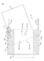
図5は、画像読取装置100に発生するジャムについて説明するための図である。   FIG. 5 is a diagram for explaining a jam that occurs in the image reading apparatus 100.

図5に示すように、原稿Pが原稿搬送方向に対して傾いて搬送されると、原稿Pの後端は原稿台103上においてサイドガイド104aを乗り越えてしまう。さらに原稿Pが搬送されると、下側筐体101と原稿台103が係合している位置の近傍において、原稿Pの端部が搬送路側壁130aにぶつかり、原稿Pにはぶつかった部分L3を中心にゆがみが発生する。その後原稿Pは、給紙ローラ111、第1搬送ローラ116及び第2搬送ローラ120により下流側に向かって搬送され、搬送にともなってゆがみが大きくなっていき、そのゆがみにより大きな音が発生する。このように原稿が傾いて搬送された結果ジャムが発生することをスキュージャムという。   As shown in FIG. 5, when the document P is conveyed while being inclined with respect to the document conveyance direction, the trailing edge of the document P gets over the side guide 104 a on the document table 103. When the document P is further conveyed, in the vicinity of the position where the lower casing 101 and the document table 103 are engaged, the end portion of the document P collides with the conveyance path side wall 130a, and a portion L3 that collides with the document P. Distortion occurs around the center. Thereafter, the document P is conveyed toward the downstream side by the paper feed roller 111, the first conveyance roller 116, and the second conveyance roller 120, and the distortion increases with the conveyance, and a large noise is generated by the distortion. The occurrence of a jam as a result of the document being conveyed at an incline is called skew jam.

なお、PPC(Plain Paper Copier)用紙を用いてスキュージャムを起こして、原稿にゆがみを発生させる実験を行った結果、搬送路側壁130aにぶつかった部分L3から原稿の中心方向に向かって最大で50mmの範囲においてゆがみが確認された。   As a result of an experiment in which skew is generated using PPC (Plain Paper Copier) paper and the original is distorted, a maximum of 50 mm from the portion L3 hitting the conveyance path side wall 130a toward the center of the original. Distortion was confirmed in the range.

一方、原稿にシワがある場合、その原稿が給紙ローラ111とリタードローラ112の間を通過する時に、ジャムが発生しなくても、そのシワにより大きな音が発生する。   On the other hand, if the document has wrinkles, when the document passes between the feed roller 111 and the retard roller 112, a loud sound is generated by the wrinkles even if no jam occurs.

したがって、スキュージャムにより発生する音を良好に集音するためには、原稿の搬送方向と直交する方向において、搬送路側壁130aに可能な限り近い位置に第1マイクロフォン113aが配置され、搬送路側壁130bに可能な限り近い位置に第2マイクロフォン113bが配置されることが好ましい。また、シワにより発生する音をなるべく集音しないようにするためには、原稿の搬送方向と直交する方向において、原稿の中心近傍に配置される給紙ローラ111及びリタードローラ112から可能な限り遠い位置に第1マイクロフォン113a及び第2マイクロフォン113bが配置されることが好ましい。つまり、スキュージャムにより発生する音を良好に集音するためには、図5の領域R4a内のように搬送路側壁130aの近傍に第1マイクロフォン113aが配置され、領域R4b内のように搬送路側壁130bの近傍に第2マイクロフォン113bが配置されることが好ましい。特に、上記の実験結果をふまえて、搬送路側壁130aから50mm以内に第1マイクロフォン113aが配置され、搬送路側壁130bから50mm以内に第2マイクロフォン113bが配置されることが好ましい。   Therefore, in order to collect sound generated by skew jam well, the first microphone 113a is disposed as close as possible to the conveyance path side wall 130a in the direction orthogonal to the document conveyance direction, and the conveyance path side wall is arranged. The second microphone 113b is preferably arranged at a position as close as possible to 130b. Further, in order to minimize the sound generated by the wrinkles, it is as far as possible from the feed roller 111 and the retard roller 112 arranged in the vicinity of the center of the document in the direction orthogonal to the document transport direction. It is preferable that the first microphone 113a and the second microphone 113b are arranged at the positions. That is, in order to collect the sound generated by the skew jam well, the first microphone 113a is disposed in the vicinity of the conveyance path side wall 130a as in the area R4a of FIG. 5, and the conveyance path as in the area R4b. The second microphone 113b is preferably disposed in the vicinity of the side wall 130b. In particular, based on the above experimental results, it is preferable that the first microphone 113a is disposed within 50 mm from the conveyance path side wall 130a and the second microphone 113b is disposed within 50 mm from the conveyance path side wall 130b.

図6は、画像読取装置100に発生する他のジャムについて説明するための図である。   FIG. 6 is a diagram for explaining another jam that occurs in the image reading apparatus 100.

図6は、ステイプルSで綴じられた原稿Pがその綴じられた部分を下流側に向けて搬送される場合の例を示している。一般に、ステイプルで綴じられる原稿は、A4サイズ、B5サイズ等のある程度のサイズ以上の原稿である場合が多く、その原稿の四隅のうちの何れかがステイプルで綴じられることとなる。ステイプルSで綴じられた原稿Pが、その綴じられた部分を下流側に向けて画像読取装置100で搬送されてしまうと、給紙ローラ111及びリタードローラ112により、原稿Pのうち給紙ローラ111と接触している原稿P1のみが搬送されようとする。この原稿P1は、第1搬送ローラ116及び第1従動ローラ117により、さらに下流側に向かって搬送されようとする。一方、原稿P1以外の原稿はステイプルSで綴じられているため搬送されない。   FIG. 6 shows an example in which the document P bound by the staple S is conveyed with the bound portion directed downstream. In general, a document that is bound by staple is often a document that is larger than a certain size such as A4 size and B5 size, and any one of four corners of the document is stapled. When the original P bound by the staple S is conveyed by the image reading apparatus 100 with the bound portion facing downstream, the paper feed roller 111 of the original P is fed by the paper feed roller 111 and the retard roller 112. Only the document P1 that is in contact with the paper is about to be conveyed. The original P1 is about to be conveyed further downstream by the first conveying roller 116 and the first driven roller 117. On the other hand, documents other than the document P1 are not conveyed because they are bound by the staple S.

したがって、原稿P1はステイプルSを中心に回転し、ゆがみが発生して、そのゆがみにより大きな音が発生する。このゆがみは、原稿搬送方向と直交する方向においては、ステイプルSで綴じられた部分L4から、原稿Pを分離する給紙ローラ111a及びリタードローラ112aまでの範囲に発生する。また、このゆがみは、原稿搬送方向においては、ステイプルSで綴じられた部分L4から、原稿P1を下流側に搬送する第1搬送ローラ116a及び第1従動ローラ117aまでの範囲に発生する。このようにステイプルで綴じられた原稿が搬送された結果ジャムが発生することをステイプルジャムという。   Accordingly, the document P1 rotates around the staple S, and distortion occurs, and a loud sound is generated due to the distortion. This distortion occurs in a range from the portion L4 bound by the staple S to the sheet feed roller 111a and the retard roller 112a that separate the document P in the direction orthogonal to the document transport direction. Further, this distortion occurs in a range from the portion L4 bound by the staple S to the first transport roller 116a and the first driven roller 117a that transport the document P1 downstream in the document transport direction. The occurrence of a jam as a result of transporting an original document stapled in this manner is called a staple jam.

したがって、ステイプルジャムにより発生する音を良好に集音するためには、図6の領域R1内のように、原稿の搬送方向において、ステイプルSで綴じられた部分L4が搬送されずに停止する給紙ローラ111及びリタードローラ112の位置と、第1搬送ローラ116及び第1従動ローラ117の位置との間にマイクロフォンが配置されることが好ましい。なお、給紙ローラ111及びリタードローラ112と、第1搬送ローラ116及び第1従動ローラ117との間にマイクロフォンを配置することにより、筐体外部で発生した音の集音を抑制することも可能となる。   Therefore, in order to collect the sound generated by the staple jam well, the portion L4 bound by the staple S is stopped without being conveyed in the document conveying direction as in the region R1 of FIG. A microphone is preferably disposed between the position of the paper roller 111 and the retard roller 112 and the position of the first transport roller 116 and the first driven roller 117. In addition, it is also possible to suppress the sound collection of the sound generated outside the housing by arranging a microphone between the paper feed roller 111 and the retard roller 112, and the first transport roller 116 and the first driven roller 117. It becomes.

また、搬送される原稿の両端の位置はその原稿のサイズによって異なるが、上述したように、ステイプルで綴じられる原稿は、A4サイズ、B5サイズ等のある程度のサイズ以上の原稿である場合が多く、サイズが大きい原稿ほどステイプルで綴じられている可能性が高い。したがって、第1マイクロフォン113a及び第2マイクロフォン113bは、画像読取装置100が保証する最大幅の原稿がステイプルで綴じられたまま搬送された場合に、ステイプルジャムと判定できるように配置されることが好ましい。原稿の搬送方向と直交する方向において、最大幅の原稿の端部の位置は、最大幅の原稿を搬送する場合にサイドガイド104aが配置される位置である。つまり、原稿の搬送方向と直交する方向においては、図6の領域R5a内及び領域R5b内のように、最大幅の原稿を搬送する場合にサイドガイド104aが配置される位置から給紙ローラ111及びリタードローラ112の位置までの範囲に第1マイクロフォン113a及び第2マイクロフォン113bが配置されることが好ましい。なお、領域R5aは、給紙ローラ111a及びリタードローラ112a自体を含む領域であり、領域R5bは、給紙ローラ111b及びリタードローラ112b自体を含む領域である。   Further, although the positions of both ends of the conveyed document vary depending on the size of the document, as described above, the document to be bound by the staple is often a document of a certain size or more such as A4 size and B5 size. A document with a larger size is more likely to be stapled. Therefore, it is preferable that the first microphone 113a and the second microphone 113b are arranged so that a staple jam can be determined when a document having a maximum width guaranteed by the image reading apparatus 100 is conveyed while being stapled. . In the direction orthogonal to the document conveyance direction, the position of the end of the document with the maximum width is the position where the side guide 104a is arranged when the document with the maximum width is conveyed. That is, in the direction orthogonal to the document conveyance direction, as shown in the region R5a and the region R5b in FIG. It is preferable that the first microphone 113a and the second microphone 113b are arranged in a range up to the position of the retard roller 112. The region R5a is a region including the paper feed roller 111a and the retard roller 112a itself, and the region R5b is a region including the paper feed roller 111b and the retard roller 112b itself.

したがって、スキュージャムにより発生する音及びステイプルジャムにより発生する音の両方を良好に集音するためには、図5の領域R4aと図6の領域R1とが重なった図4の領域R2aに第1マイクロフォン113aが配置され、領域R4bと領域R1とが重なった領域R2bに第2マイクロフォン113bが配置されることが好ましい。さらに、図5の領域R4aと図6の領域R5aとが重なった図4の領域R3aに第1マイクロフォン113aが配置され、領域R4bと領域R5bとが重なった領域R3bに第2マイクロフォン113bが配置されることがより好ましい。   Therefore, in order to satisfactorily collect both the sound generated by skew jam and the sound generated by staple jam, the region R2a in FIG. 4 where the region R4a in FIG. 5 and the region R1 in FIG. It is preferable that the microphone 113a is disposed and the second microphone 113b is disposed in a region R2b where the region R4b and the region R1 overlap. Further, the first microphone 113a is arranged in the region R3a in FIG. 4 where the region R4a in FIG. 5 and the region R5a in FIG. 6 overlap, and the second microphone 113b is arranged in the region R3b where the region R4b and the region R5b overlap. More preferably.

画像読取装置100では、領域R3aに第1マイクロフォン113aが配置され、領域R3bに第2マイクロフォン113bが配置されるので、スキュージャム及びステイプルジャムにより発生する音を良好に集音しつつ、シワにより発生する音及び筐体外部で発生した音(以下、ノイズ音と称する)を集音することを抑制することができる。   In the image reading apparatus 100, since the first microphone 113a is disposed in the region R3a and the second microphone 113b is disposed in the region R3b, the sound generated by the skew jam and the staple jam is well collected and generated by wrinkles. It is possible to suppress collecting sound and sound generated outside the housing (hereinafter referred to as noise sound).

画像読取装置100の構成では、マイクロフォン113はノイズ音も多少は集音するが、各ジャムにより発生する音に対するノイズ音の割合は小さくなる。上述した「ノイズ音を集音することを抑制する」とは、この割合を小さくすることを意味する。画像読取装置100では「ノイズ音を集音することを抑制」しているため、マイクロフォン113が出力する信号について、各ジャムにより発生する音の大きさと、ノイズ音の大きさとの間に閾値を設定し、その閾値以下となる成分をカットすることにより、ノイズ音の影響を除去することができる。   In the configuration of the image reading apparatus 100, the microphone 113 collects some noise sound, but the ratio of the noise sound to the sound generated by each jam is small. The above-mentioned “suppresses collecting noise noise” means to reduce this ratio. Since the image reading apparatus 100 “suppresses collecting noise noise”, a threshold value is set between the loudness of each jammed sound and the loudness of the noise for the signal output from the microphone 113. Then, the influence of the noise sound can be removed by cutting the components that are equal to or lower than the threshold.

図7は、画像読取装置100の概略構成を示すブロック図である。   FIG. 7 is a block diagram illustrating a schematic configuration of the image reading apparatus 100.

画像読取装置100は、前述した構成に加えて、第1画像A/D変換部140a、第2画像A/D変換部140b、第1音信号出力部141a、第2音信号出力部141b、駆動部145、インターフェース部146、記憶部147及び中央処理部150等をさらに有する。   In addition to the configuration described above, the image reading apparatus 100 includes a first image A / D conversion unit 140a, a second image A / D conversion unit 140b, a first sound signal output unit 141a, a second sound signal output unit 141b, and a drive. A unit 145, an interface unit 146, a storage unit 147, a central processing unit 150, and the like.

第1画像A/D変換部140aは、第1撮像部119aから出力されたアナログの画像信号をアナログデジタル変換してデジタルの画像データを生成し、中央処理部150に出力する。同様に、第2画像A/D変換部140bは、第2撮像部119bから出力されたアナログの画像信号をアナログデジタル変換してデジタルの画像データを生成し、中央処理部150に出力する。以下、これらのデジタルの画像データを読取画像と称する。   The first image A / D conversion unit 140 a performs analog-digital conversion on the analog image signal output from the first imaging unit 119 a to generate digital image data, and outputs the digital image data to the central processing unit 150. Similarly, the second image A / D conversion unit 140b converts the analog image signal output from the second imaging unit 119b from analog to digital, generates digital image data, and outputs the digital image data to the central processing unit 150. Hereinafter, these digital image data are referred to as read images.

第1音信号出力部141aは、第1マイクロフォン113a、第1フィルタ部142a、第1増幅部143a及び第1音A/D変換部144a等を含んでいる。第1フィルタ部142aは、第1マイクロフォン113aから出力されたアナログの信号に対して、予め定められた周波数帯域の信号を通過させるバンドパスフィルタを適用し、第1増幅部143aに出力する。第1増幅部143aは、第1フィルタ部142aから出力された信号を増幅させて第1音A/D変換部144aに出力する。第1音A/D変換部144aは、第1増幅部143aから出力されたアナログ信号をデジタル信号に変換し、中央処理部150に出力する。以下、第1音信号出力部141aが出力する信号を第1音信号と称する。   The first sound signal output unit 141a includes a first microphone 113a, a first filter unit 142a, a first amplification unit 143a, a first sound A / D conversion unit 144a, and the like. The first filter unit 142a applies a bandpass filter that passes a signal in a predetermined frequency band to the analog signal output from the first microphone 113a, and outputs the signal to the first amplifying unit 143a. The first amplification unit 143a amplifies the signal output from the first filter unit 142a and outputs the amplified signal to the first sound A / D conversion unit 144a. The first sound A / D conversion unit 144 a converts the analog signal output from the first amplification unit 143 a into a digital signal and outputs the digital signal to the central processing unit 150. Hereinafter, the signal output from the first sound signal output unit 141a is referred to as a first sound signal.

なお、第1音信号出力部141aは、これに限定されない。第1音信号出力部141aは、第1マイクロフォン113aのみを含み、第1フィルタ部142a、第1増幅部143a及び第1音A/D変換部144aは、第1音信号出力部141aの外部に備えられてもよい。また、第1音信号出力部141aは、第1マイクロフォン113a及び第1フィルタ部142aのみ、あるいは第1マイクロフォン113a、第1フィルタ部142a及び第1増幅部143aのみを含んでもよい。   The first sound signal output unit 141a is not limited to this. The first sound signal output unit 141a includes only the first microphone 113a, and the first filter unit 142a, the first amplification unit 143a, and the first sound A / D conversion unit 144a are provided outside the first sound signal output unit 141a. It may be provided. The first sound signal output unit 141a may include only the first microphone 113a and the first filter unit 142a, or only the first microphone 113a, the first filter unit 142a, and the first amplification unit 143a.

第2音信号出力部141bは、第2マイクロフォン113b、第2フィルタ部142b、第2増幅部143b及び第2音A/D変換部144b等を含んでいる。第2フィルタ部142bは、第2マイクロフォン113bから出力されたアナログの信号に対して、予め定められた周波数帯域の信号を通過させるバンドパスフィルタを適用し、第2増幅部143bに出力する。第2増幅部143bは、第2フィルタ部142bから出力された信号を増幅させて第2音A/D変換部144bに出力する。第2音A/D変換部144bは、第2増幅部143bから出力されたアナログの信号をデジタルの第2音信号に変換し、中央処理部150に出力する。以下、第2音信号出力部141bが出力する信号を第2音信号と称する。   The second sound signal output unit 141b includes a second microphone 113b, a second filter unit 142b, a second amplification unit 143b, a second sound A / D conversion unit 144b, and the like. The second filter unit 142b applies a bandpass filter that passes a signal in a predetermined frequency band to the analog signal output from the second microphone 113b, and outputs the signal to the second amplifying unit 143b. The second amplification unit 143b amplifies the signal output from the second filter unit 142b and outputs the amplified signal to the second sound A / D conversion unit 144b. The second sound A / D conversion unit 144 b converts the analog signal output from the second amplification unit 143 b into a digital second sound signal and outputs the digital second sound signal to the central processing unit 150. Hereinafter, the signal output from the second sound signal output unit 141b is referred to as a second sound signal.

なお、第2音信号出力部141bは、これに限定されない。第2音信号出力部141bは、第2マイクロフォン113bのみを含み、第2フィルタ部142b、第2増幅部143b及び第2音A/D変換部144bは、第2音信号出力部141bの外部に備えられてもよい。また、第2音信号出力部141bは、第2マイクロフォン113b及び第2フィルタ部142bのみ、あるいは第2マイクロフォン113b、第2フィルタ部142b及び第2増幅部143bのみを含んでもよい。   In addition, the 2nd sound signal output part 141b is not limited to this. The second sound signal output unit 141b includes only the second microphone 113b, and the second filter unit 142b, the second amplification unit 143b, and the second sound A / D conversion unit 144b are provided outside the second sound signal output unit 141b. It may be provided. The second sound signal output unit 141b may include only the second microphone 113b and the second filter unit 142b, or only the second microphone 113b, the second filter unit 142b, and the second amplification unit 143b.

駆動部145は、1つ又は複数のモータを含み、中央処理部150からの制御信号によって、給紙ローラ111、リタードローラ112、第1搬送ローラ116及び第2搬送ローラ120を回転させて原稿の搬送動作を行う。   The driving unit 145 includes one or a plurality of motors, and rotates the paper feeding roller 111, the retard roller 112, the first conveying roller 116, and the second conveying roller 120 according to a control signal from the central processing unit 150, so Carry out the transfer operation.

インターフェース部146は、例えばUSB等のシリアルバスに準じるインターフェース回路を有し、不図示の情報処理装置(例えば、パーソナルコンピュータ、携帯情報端末等)と電気的に接続して読取画像及び各種の情報を送受信する。また、インターフェース部146にフラッシュメモリ等を接続して読取画像を保存するようにしてもよい。   The interface unit 146 has an interface circuit conforming to a serial bus such as a USB, for example, and is electrically connected to an information processing device (not shown) (for example, a personal computer, a portable information terminal, etc.) to display a read image and various information. Send and receive. Further, a read image may be stored by connecting a flash memory or the like to the interface unit 146.

記憶部147は、RAM(Random Access Memory)、ROM(Read Only Memory)等のメモリ装置、ハードディスク等の固定ディスク装置、又はフレキシブルディスク、光ディスク等の可搬用の記憶装置等を有する。また、記憶部147には、画像読取装置100の各種処理に用いられるコンピュータプログラム、データベース、テーブル等が格納される。コンピュータプログラムは、例えばCD−ROM(compact disk read only memory)、DVD−ROM(digital versatile disk read only memory)等のコンピュータ読み取り可能な可搬型記録媒体から、公知のセットアッププログラム等を用いて記憶部147にインストールされてもよい。さらに、記憶部147には、読取画像が格納される。   The storage unit 147 includes a memory device such as a RAM (Random Access Memory) and a ROM (Read Only Memory), a fixed disk device such as a hard disk, or a portable storage device such as a flexible disk and an optical disk. In addition, the storage unit 147 stores computer programs, databases, tables, and the like used for various processes of the image reading apparatus 100. The computer program is stored in a storage unit 147 from a computer-readable portable recording medium such as a CD-ROM (compact disk read only memory) or a DVD-ROM (digital versatile disk read only memory) using a known setup program. May be installed. Further, the storage unit 147 stores the read image.

中央処理部150は、CPU(Central Processing Unit)を備え、予め記憶部147に記憶されているプログラムに基づいて動作する。なお、中央処理部150は、DSP(digital signal processor)、LSI(large scale integration)、ASIC(Application Specific Integrated Circuit)、FPGA(Field-Programming Gate Array)等で構成されてもよい。   The central processing unit 150 includes a CPU (Central Processing Unit) and operates based on a program stored in the storage unit 147 in advance. The central processing unit 150 may be configured by a digital signal processor (DSP), a large scale integration (LSI), an application specific integrated circuit (ASIC), a field-programming gate array (FPGA), or the like.

中央処理部150は、操作ボタン106、第1原稿検出部110、第2原稿検出部114、超音波センサ115、第3原稿検出部118、第1撮像部119a、第2撮像部119b、第1画像A/D変換部140a、第2画像A/D変換部140b、第1音信号出力部141a、第2音信号出力部141b、駆動部145、インターフェース部146及び記憶部147と接続され、これらの各部を制御する。   The central processing unit 150 includes the operation button 106, the first document detection unit 110, the second document detection unit 114, the ultrasonic sensor 115, the third document detection unit 118, the first imaging unit 119a, the second imaging unit 119b, and the first. Connected to the image A / D converter 140a, the second image A / D converter 140b, the first sound signal output unit 141a, the second sound signal output unit 141b, the drive unit 145, the interface unit 146, and the storage unit 147. Control each part.

中央処理部150は、駆動部145の駆動制御、撮像部119の原稿読取制御等を行い、読取画像を取得する。また、中央処理部150は、制御部151、画像生成部152、音ジャム判定部153、位置ジャム判定部154及び重送判定部155等を有する。これらの各部は、プロセッサ上で動作するソフトウェアにより実装される機能モジュールである。なお、これらの各部は、それぞれ独立した集積回路、マイクロプロセッサ、ファームウェア等で構成されてもよい。   The central processing unit 150 performs drive control of the drive unit 145, document reading control of the imaging unit 119, and the like, and acquires a read image. The central processing unit 150 includes a control unit 151, an image generation unit 152, a sound jam determination unit 153, a position jam determination unit 154, a multifeed determination unit 155, and the like. Each of these units is a functional module implemented by software operating on the processor. Each of these units may be configured by an independent integrated circuit, a microprocessor, firmware, and the like.

図8は、画像読取装置100の全体処理の動作の例を示すフローチャートである。   FIG. 8 is a flowchart illustrating an example of the operation of the entire process of the image reading apparatus 100.

以下、図8に示したフローチャートを参照しつつ、画像読取装置100の全体処理の動作の例を説明する。なお、以下に説明する動作のフローは、予め記憶部147に記憶されているプログラムに基づき主に中央処理部150により画像読取装置100の各要素と協働して実行される。   Hereinafter, an example of the overall processing operation of the image reading apparatus 100 will be described with reference to the flowchart shown in FIG. The operation flow described below is mainly executed by the central processing unit 150 in cooperation with each element of the image reading apparatus 100 based on a program stored in the storage unit 147 in advance.

最初に、中央処理部150は、利用者により操作ボタン106が押下されて、操作ボタン106から操作検出信号を受信するまで待機する(ステップS101)。   First, the central processing unit 150 waits until the user presses the operation button 106 and receives an operation detection signal from the operation button 106 (step S101).

次に、中央処理部150は、第1原稿検出部110から受信する第1原稿検出信号に基づいて原稿台103に原稿が載置されているか否かを判定する(ステップS102)。   Next, the central processing unit 150 determines whether or not a document is placed on the document table 103 based on the first document detection signal received from the first document detection unit 110 (step S102).

原稿台103に原稿が載置されていない場合、中央処理部150は、ステップS101へ処理を戻し、操作ボタン106から新たに操作検出信号を受信するまで待機する。   If no document is placed on the document table 103, the central processing unit 150 returns the process to step S101 and waits until a new operation detection signal is received from the operation button 106.

一方、原稿台103に原稿が載置されている場合、中央処理部150は、駆動部145を駆動して給紙ローラ111、リタードローラ112、第1搬送ローラ116及び第2搬送ローラ120を回転させて、原稿を搬送させる(ステップS103)。   On the other hand, when the document is placed on the document table 103, the central processing unit 150 drives the drive unit 145 to rotate the paper feed roller 111, the retard roller 112, the first transport roller 116, and the second transport roller 120. Thus, the document is conveyed (step S103).

次に、制御部151は、異常発生フラグがONであるか否かを判定する(ステップS104)。この異常発生フラグは、画像読取装置100の起動時にOFFに設定され、後述する異常判定処理で異常が発生したと判定されるとONに設定される。   Next, the control unit 151 determines whether or not the abnormality occurrence flag is ON (step S104). This abnormality occurrence flag is set to OFF when the image reading apparatus 100 is activated, and is set to ON when it is determined that an abnormality has occurred in an abnormality determination process described later.

異常発生フラグがONである場合、制御部151は、異常処理として、駆動部145を停止して、原稿の搬送を停止させるとともに、不図示のスピーカ、LED(Light Emitting Diode)等により、異常が発生したことを利用者に通知し、異常発生フラグをOFFに設定し(ステップS105)、一連のステップを終了する。   When the abnormality occurrence flag is ON, the control unit 151 stops the driving unit 145 as the abnormality process to stop the conveyance of the document, and an abnormality is caused by a not-shown speaker, LED (Light Emitting Diode), or the like. The occurrence is notified to the user, the abnormality occurrence flag is set to OFF (step S105), and the series of steps is terminated.

一方、異常判定フラグがONでない場合、画像生成部152は、搬送された原稿を第1撮像部119a及び第2撮像部119bに読み取らせ、第1画像A/D変換部140a及び第2画像A/D変換部140bを介して読取画像を取得する(ステップS106)。   On the other hand, if the abnormality determination flag is not ON, the image generation unit 152 causes the first imaging unit 119a and the second imaging unit 119b to read the conveyed document, and the first image A / D conversion unit 140a and the second image A A read image is acquired via the / D conversion unit 140b (step S106).

次に、中央処理部150は、取得した読取画像をインターフェース部146を介して不図示の情報処理装置へ送信する(ステップS107)。なお、情報処理装置と接続されていない場合、中央処理部150は、取得した読取画像を記憶部147に記憶しておく。   Next, the central processing unit 150 transmits the acquired read image to the information processing apparatus (not shown) via the interface unit 146 (step S107). If the information processing apparatus is not connected, the central processing unit 150 stores the acquired read image in the storage unit 147.

次に、中央処理部150は、第1原稿検出部110から受信する第1原稿検出信号に基づいて原稿台103に原稿が残っているか否かを判定する(ステップS108)。   Next, central processing unit 150 determines whether or not a document remains on document table 103 based on the first document detection signal received from first document detection unit 110 (step S108).

原稿台103に原稿が残っている場合、中央処理部150は、ステップS103へ処理を戻し、ステップS103〜S108の処理を繰り返す。一方、原稿台103に原稿が残っていない場合、中央処理部150は、一連の処理を終了する。   If a document remains on the document table 103, the central processing unit 150 returns the process to step S103 and repeats the processes of steps S103 to S108. On the other hand, if no document remains on the document table 103, the central processing unit 150 ends the series of processes.

図9は、画像読取装置100の異常判定処理の動作の例を示すフローチャートである。   FIG. 9 is a flowchart illustrating an example of the operation of the abnormality determination process of the image reading apparatus 100.

以下に説明する動作のフローは、予め記憶部147に記憶されているプログラムに基づき主に中央処理部150により画像読取装置100の各要素と協働して実行される。   The flow of operations described below is mainly executed by the central processing unit 150 in cooperation with each element of the image reading apparatus 100 based on a program stored in the storage unit 147 in advance.

最初に、音ジャム判定部153は、音ジャム判定処理を実施する(ステップS201)。音ジャム判定部153は、音ジャム判定処理において、第1音信号出力部141aから取得した第1音信号、及び第2音信号出力部141bから取得した第2音信号に基づいてジャムが発生したか否かを判定する。以下、音ジャム判定部153が第1音信号及び第2音信号に基づいて発生の有無を判定するジャムのことを音ジャムと称する場合がある。音ジャム判定処理の詳細については後述する。   First, the sound jam determination unit 153 performs a sound jam determination process (step S201). In the sound jam determination process, the sound jam determination unit 153 generates a jam based on the first sound signal acquired from the first sound signal output unit 141a and the second sound signal acquired from the second sound signal output unit 141b. It is determined whether or not. Hereinafter, the jam in which the sound jam determination unit 153 determines whether or not the sound jam occurs based on the first sound signal and the second sound signal may be referred to as a sound jam. Details of the sound jam determination process will be described later.

次に、位置ジャム判定部154は、位置ジャム判定処理を実施する(ステップS202)。位置ジャム判定部154は、位置ジャム判定処理において、第2原稿検出部114から取得した第2原稿検出信号と、第3原稿検出部118から取得した第3原稿検出信号とに基づいてジャムが発生したか否かを判定する。以下、位置ジャム判定部154が第2原稿検出信号及び第3原稿検出信号に基づいて発生の有無を判定するジャムのことを位置ジャムと称する場合がある。位置ジャム判定処理の詳細については後述する。   Next, the position jam determination unit 154 performs position jam determination processing (step S202). The position jam determination unit 154 generates a jam based on the second document detection signal acquired from the second document detection unit 114 and the third document detection signal acquired from the third document detection unit 118 in the position jam determination process. Determine whether or not. Hereinafter, the jam in which the position jam determination unit 154 determines whether or not it occurs based on the second document detection signal and the third document detection signal may be referred to as a position jam. Details of the position jam determination process will be described later.

次に、重送判定部155は、重送判定処理を実施する(ステップS203)。重送判定部155は、重送判定処理において、超音波センサ115から取得した超音波信号に基づいて原稿の重送が発生したか否かを判定する。重送判定処理の詳細については後述する。   Next, the double feed determination unit 155 performs a double feed determination process (step S203). In the double feed determination process, the double feed determination unit 155 determines whether double feed of the document has occurred based on the ultrasonic signal acquired from the ultrasonic sensor 115. Details of the double feed determination process will be described later.

次に、制御部151は、原稿搬送処理に異常が発生したか否かを判定する(ステップS204)。制御部151は、音ジャム、位置ジャム及び原稿の重送のうちの少なくとも一つが発生した場合、異常が発生したと判定する。すなわち、音ジャム、位置ジャム及び原稿の重送の何れも発生していない場合にのみ、異常が発生していないと判定する。   Next, the control unit 151 determines whether or not an abnormality has occurred in the document conveyance process (step S204). The control unit 151 determines that an abnormality has occurred when at least one of a sound jam, a position jam, and a document double feed has occurred. That is, it is determined that no abnormality has occurred only when none of the sound jam, the position jam, or the double feed of the document has occurred.

制御部151は、原稿搬送処理に異常が発生した場合、異常発生フラグをONに設定し(ステップS205)、一連のステップを終了する。一方、原稿搬送処理に異常が発生していない場合、特に処理を行わず、一連のステップを終了する。なお、図9に示すフローチャートは、所定の時間間隔ごとに実行される。   When an abnormality occurs in the document conveyance process, the control unit 151 sets the abnormality occurrence flag to ON (step S205) and ends a series of steps. On the other hand, if no abnormality has occurred in the document conveying process, no particular process is performed and the series of steps is terminated. Note that the flowchart shown in FIG. 9 is executed at predetermined time intervals.

図10は、音ジャム判定処理の動作の例を示すフローチャートである。   FIG. 10 is a flowchart showing an example of the operation of the sound jam determination process.

図10に示す動作のフローは、図9に示すフローチャートのステップS201において実行される。   The operation flow shown in FIG. 10 is executed in step S201 of the flowchart shown in FIG.

最初に、音ジャム判定部153は、第1音信号出力部141aから第1音信号を取得し、第2音信号出力部141bから第2音信号を取得する(ステップS301)。   First, the sound jam determination unit 153 acquires the first sound signal from the first sound signal output unit 141a, and acquires the second sound signal from the second sound signal output unit 141b (step S301).

次に、音ジャム判定部153は、第1音信号について絶対値を取った第1絶対値信号、及び、第2音信号について絶対値を取った第2絶対値信号を生成する(ステップS302)。   Next, the sound jam determination unit 153 generates a first absolute value signal that takes an absolute value for the first sound signal and a second absolute value signal that takes an absolute value for the second sound signal (step S302). .

次に、音ジャム判定部153は、第1絶対値信号の外形を抽出した第1外形信号、及び、第2絶対値信号の外形を抽出した第2外形信号を生成する(ステップS303)。音ジャム判定部153は、第1外形信号及び第2外形信号として、それぞれ第1絶対値信号及び第2絶対値信号についてピークホールドを取った信号を生成する。音ジャム判定部153は、各絶対値信号の極大値を一定のホールド期間だけホールドし、その後一定の減衰率で減衰させることにより各外形信号を生成する。   Next, the sound jam determination unit 153 generates a first outline signal obtained by extracting the outline of the first absolute value signal and a second outline signal obtained by extracting the outline of the second absolute value signal (step S303). The sound jam determination unit 153 generates signals having peak hold for the first absolute value signal and the second absolute value signal, respectively, as the first external shape signal and the second external shape signal. The sound jam determination unit 153 generates each outline signal by holding the local maximum value of each absolute value signal for a fixed hold period and then attenuating it at a constant attenuation rate.

次に、音ジャム判定部153は、第1外形信号の信号値について、第1の閾値Th1以上である場合に増大させ、第1の閾値Th1未満である場合に減少させる第1カウンタ値を算出する。同様に、音ジャム判定部153は、第2外形信号の信号値について、第1の閾値Th1以上である場合に増大させ、第1の閾値Th1未満である場合に減少させる第2カウンタ値を算出する(ステップS304)。   Next, the sound jam determination unit 153 calculates a first counter value that is increased when the signal value of the first outer shape signal is equal to or greater than the first threshold value Th1 and decreased when the signal value is less than the first threshold value Th1. To do. Similarly, the sound jam determination unit 153 calculates a second counter value that increases when the signal value of the second contour signal is equal to or greater than the first threshold Th1 and decreases when the signal value is less than the first threshold Th1. (Step S304).

音ジャム判定部153は、所定の時間間隔(例えば音信号のサンプリング間隔)ごとに、第1外形信号の信号値が第1の閾値Th1以上であるか否かを判定し、第1外形信号の信号値が第1の閾値Th1以上である場合、第1カウンタ値をインクリメントし、第1の閾値Th1未満である場合、第1カウンタ値をデクリメントする。同様に、音ジャム判定部153は、所定の時間間隔ごとに、第2外形信号の信号値が第1の閾値Th1以上であるか否かを判定し、第2外形信号の信号値が第1の閾値Th1以上である場合、第2カウンタ値をインクリメントし、第1の閾値Th1未満である場合、第2カウンタ値をデクリメントする。   The sound jam determination unit 153 determines whether or not the signal value of the first contour signal is equal to or greater than the first threshold Th1 at predetermined time intervals (for example, the sampling interval of the sound signal). When the signal value is equal to or greater than the first threshold value Th1, the first counter value is incremented. When the signal value is less than the first threshold value Th1, the first counter value is decremented. Similarly, the sound jam determination unit 153 determines whether the signal value of the second contour signal is equal to or greater than the first threshold Th1 at predetermined time intervals, and the signal value of the second contour signal is the first value. If the threshold value Th1 is equal to or greater than the threshold value Th1, the second counter value is incremented. If it is less than the first threshold value Th1, the second counter value is decremented.

次に、音ジャム判定部153は、第1カウンタ値及び第2カウンタ値のうちの少なくとも一方が第2の閾値Th2以上であるか否かを判定する(ステップS305)。音ジャム判定部153は、第1カウンタ値及び第2カウンタ値のうちの少なくとも一方が第2の閾値Th2以上であれば音ジャムが発生したと判定する(ステップS306)。一方、音ジャム判定部153は、第1カウンタ値及び第2カウンタ値の両方が第2の閾値Th2未満であれば音ジャムは発生していないと判定し(ステップS307)、一連のステップを終了する。   Next, the sound jam determination unit 153 determines whether at least one of the first counter value and the second counter value is equal to or greater than the second threshold Th2 (step S305). The sound jam determination unit 153 determines that a sound jam has occurred if at least one of the first counter value and the second counter value is equal to or greater than the second threshold Th2 (step S306). On the other hand, if both the first counter value and the second counter value are less than the second threshold value Th2, the sound jam determination unit 153 determines that no sound jam has occurred (step S307), and ends the series of steps. To do.

以下、第1マイクロフォン113a及び第2マイクロフォン113aを本実施形態のように配置した場合の音ジャムの判定結果と、他の位置に配置した場合の音ジャムの判定結果とを比較して説明する。   Hereinafter, the determination result of the sound jam when the first microphone 113a and the second microphone 113a are arranged as in the present embodiment and the determination result of the sound jam when arranged at other positions will be described.

図11は、第1マイクロフォン113aの配置位置を説明するための図である。   FIG. 11 is a diagram for explaining the arrangement position of the first microphone 113a.

位置L5は、原稿の搬送方向において、給紙ローラ111及びリタードローラ112と、第1搬送ローラ116及び第1従動ローラ117との間の中心の位置であり、原稿の搬送方向と直交する方向において、搬送路側壁130aから25mmの位置である。つまり、位置L5は、図4の領域R3aに含まれ、スキュージャムにより発生する音及びステイプルジャムにより発生する音の両方を良好に集音できる位置である。   The position L5 is a center position between the paper feed roller 111 and the retard roller 112, and the first transport roller 116 and the first driven roller 117 in the document transport direction, and in the direction orthogonal to the document transport direction. The position is 25 mm from the conveyance path side wall 130a. That is, the position L5 is a position that is included in the region R3a of FIG. 4 and that can properly collect both the sound generated by the skew jam and the sound generated by the staple jam.

位置L6は、原稿の搬送方向において、第1搬送ローラ116及び第1従動ローラ117より下流側の位置であり、原稿の搬送方向と直交する方向において、搬送路側壁130aから25mmの位置である。つまり、位置L6は、領域R3aには含まれず、スキュージャムにより発生する音を良好に集音できるが、ステイプルジャムにより発生する音を良好に集音できない位置である。   The position L6 is a position downstream of the first conveyance roller 116 and the first driven roller 117 in the document conveyance direction, and is a position 25 mm from the conveyance path side wall 130a in the direction orthogonal to the document conveyance direction. That is, the position L6 is not included in the region R3a and is a position where sound generated by skew jam can be collected well, but sound generated by staple jam cannot be collected well.

位置L7は、給紙ローラ111及びリタードローラ112と、第1搬送ローラ116及び第1従動ローラ117との間の中心の位置であり、原稿の搬送方向と直交する方向において、搬送路側壁130aから60mmの位置である。つまり、位置L7は、領域R3aには含まれず、ステイプルジャムにより発生する音を良好に集音できるが、スキュージャムにより発生する音を良好に集音できない位置である。   The position L7 is a central position between the paper feed roller 111 and the retard roller 112, and the first conveyance roller 116 and the first driven roller 117. From the conveyance path side wall 130a in the direction orthogonal to the document conveyance direction. The position is 60 mm. In other words, the position L7 is not included in the region R3a, and is a position where sound generated by staple jam can be collected well, but sound generated by skew jam cannot be collected well.

図12は、第1マイクロフォン113aが図11の位置L5に配置され、スキュージャムが発生した場合の音ジャム判定についての各信号の例を示すグラフである。   FIG. 12 is a graph showing an example of each signal regarding sound jam determination when the first microphone 113a is arranged at the position L5 in FIG. 11 and skew jam occurs.

図12A、図12B及び図12Cの横軸は時間を示し、図12A及び図12Bの縦軸は信号値を示し、図12Cの縦軸はカウンタ値を示す。図12Aのグラフは、第1マイクロフォン113aが図11の位置L5に配置され、図5に示したように、第1マイクロフォン113aの近傍の搬送路側壁130aに原稿がぶつかってスキュージャムが発生した場合の第1絶対値信号1201の例を表す。図12Bのグラフは、第1絶対値信号1201から生成された第1外形信号1211の例を表す。図12Cのグラフは、第1外形信号1211について算出された第1カウンタ値1221の例を表す。   The horizontal axes of FIGS. 12A, 12B, and 12C indicate time, the vertical axes of FIGS. 12A and 12B indicate signal values, and the vertical axis of FIG. 12C indicates counter values. The graph of FIG. 12A shows the case where the first microphone 113a is arranged at the position L5 in FIG. 11, and as shown in FIG. An example of the first absolute value signal 1201 is shown. The graph of FIG. 12B represents an example of the first external shape signal 1211 generated from the first absolute value signal 1201. The graph of FIG. 12C represents an example of the first counter value 1221 calculated for the first outer shape signal 1211.

図12Bにおいて、第1外形信号1211は、時刻T1で第1の閾値Th1以上となり、その後、頻繁に第1の閾値Th1以上となる。図12Cに示すように、第1カウンタ値1221は時刻T1から増大し、その後、増減を繰り返しながら時刻T2で第2の閾値Th2以上となり、音ジャムが発生したと判定される。   In FIG. 12B, the first contour signal 1211 becomes equal to or higher than the first threshold Th1 at time T1, and then frequently becomes equal to or higher than the first threshold Th1. As shown in FIG. 12C, the first counter value 1221 increases from time T1, and after that, while increasing and decreasing, becomes equal to or greater than the second threshold Th2 at time T2, and it is determined that a sound jam has occurred.

図13は、第1マイクロフォン113aが図11の位置L5に配置され、ステイプルジャムが発生した場合の音ジャム判定についての各信号の例を示すグラフである。   FIG. 13 is a graph showing an example of each signal for sound jam determination when the first microphone 113a is arranged at the position L5 in FIG. 11 and a staple jam occurs.

図13A、図13B及び図13Cの横軸は時間を示し、図13A及び図13Bの縦軸は信号値を示し、図13Cの縦軸はカウンタ値を示す。図13Aのグラフは、第1マイクロフォン113aが図11の位置L5に配置され、図6に示したように、ステイプルで綴じられた部分を第1マイクロフォン113a側にして搬送された原稿によりステイプルジャムが発生した場合の第1絶対値信号1301の例を表す。図13Bのグラフは、第1絶対値信号1301から生成された第1外形信号1311の例を表す。図13Cのグラフは、第1外形信号1311について算出された第1カウンタ値1321の例を表す。   13A, 13B, and 13C, the horizontal axis indicates time, the vertical axis in FIGS. 13A and 13B indicates a signal value, and the vertical axis in FIG. 13C indicates a counter value. In the graph of FIG. 13A, the first microphone 113a is arranged at the position L5 in FIG. 11, and as shown in FIG. An example of the first absolute value signal 1301 when it occurs is shown. The graph of FIG. 13B represents an example of the first external shape signal 1311 generated from the first absolute value signal 1301. The graph of FIG. 13C represents an example of the first counter value 1321 calculated for the first outer shape signal 1311.

図13Bにおいて、第1外形信号1311は、時刻T3で第1の閾値Th1以上となり、その後、頻繁に第1の閾値Th1以上となる。図13Cに示すように、第1カウンタ値1321は時刻T3から増大し、その後、増減を繰り返しながら時刻T4で第2の閾値Th2以上となり、音ジャムが発生したと判定される。   In FIG. 13B, the first external shape signal 1311 becomes equal to or higher than the first threshold Th1 at time T3, and then frequently becomes equal to or higher than the first threshold Th1. As shown in FIG. 13C, the first counter value 1321 increases from the time T3, and after that, while increasing and decreasing, becomes the second threshold Th2 or more at the time T4, and it is determined that a sound jam has occurred.

以上のように、第1マイクロフォン113aが図11の位置L5に配置された場合、音ジャム判定部153は、スキュージャムが発生した場合も、ステイプルジャムが発生した場合も、音ジャムが発生したと判定することができる。   As described above, when the first microphone 113a is disposed at the position L5 in FIG. 11, the sound jam determination unit 153 determines that a sound jam has occurred regardless of whether a skew jam has occurred or a staple jam has occurred. Can be determined.

図14は、第1マイクロフォン113aが図11の位置L6に配置され、スキュージャムが発生した場合の音ジャム判定についての各信号の例を示すグラフである。   FIG. 14 is a graph showing an example of each signal regarding sound jam determination when the first microphone 113a is arranged at the position L6 in FIG. 11 and skew jam occurs.

図14A、図14B及び図14Cの横軸は時間を示し、図14A及び図14Bの縦軸は信号値を示し、図14Cの縦軸はカウンタ値を示す。図14Aのグラフは、第1マイクロフォン113aが図11の位置L6に配置され、図5に示したように、第1マイクロフォン114aの近傍の搬送路側壁140aに原稿がぶつかってスキュージャムが発生した場合の第1絶対値信号1401の例を表す。図14Bのグラフは、第1絶対値信号1401から生成された第1外形信号1411の例を表す。図14Cのグラフは、第1外形信号1411について算出された第1カウンタ値1421の例を表す。   14A, 14B, and 14C, the horizontal axis indicates time, the vertical axis in FIGS. 14A and 14B indicates a signal value, and the vertical axis in FIG. 14C indicates a counter value. The graph of FIG. 14A shows the case where the first microphone 113a is disposed at the position L6 in FIG. 11, and as shown in FIG. An example of the first absolute value signal 1401 is shown. The graph of FIG. 14B represents an example of the first external shape signal 1411 generated from the first absolute value signal 1401. The graph of FIG. 14C represents an example of the first counter value 1421 calculated for the first outer shape signal 1411.

図14Bにおいて、第1外形信号1411は、時刻T5で第1の閾値Th1以上となり、その後、頻繁に第1の閾値Th1以上となる。図14Cに示すように、第1カウンタ値1421は時刻T5から増大し、その後、増減を繰り返しながら時刻T6で第2の閾値Th2以上となり、音ジャムが発生したと判定される。   In FIG. 14B, the first outer shape signal 1411 becomes equal to or higher than the first threshold Th1 at time T5, and then frequently becomes equal to or higher than the first threshold Th1. As shown in FIG. 14C, the first counter value 1421 increases from time T5, and after that, while increasing and decreasing, becomes the second threshold Th2 or more at time T6, and it is determined that a sound jam has occurred.

図15は、第1マイクロフォン113aが図11の位置L6に配置され、ステイプルジャムが発生した場合の音ジャム判定についての各信号の例を示すグラフである。   FIG. 15 is a graph showing an example of each signal for sound jam determination when the first microphone 113a is arranged at the position L6 in FIG. 11 and a staple jam occurs.

図15A、図15B及び図15Cの横軸は時間を示し、図15A及び図15Bの縦軸は信号値を示し、図15Cの縦軸はカウンタ値を示す。図15Aのグラフは、第1マイクロフォン113aが図11の位置L6に配置され、図6に示したように、ステイプルで綴じられた部分を第1マイクロフォン113a側にして搬送された原稿によりステイプルジャムが発生した場合の第1絶対値信号1501の例を表す。図15Bのグラフは、第1絶対値信号1501から生成された第1外形信号1511の例を表す。図15Cのグラフは、第1外形信号1511について算出された第1カウンタ値1521の例を表す。   The horizontal axis of FIGS. 15A, 15B, and 15C indicates time, the vertical axis of FIGS. 15A and 15B indicates a signal value, and the vertical axis of FIG. 15C indicates a counter value. In the graph of FIG. 15A, the first microphone 113a is arranged at the position L6 in FIG. 11, and as shown in FIG. An example of the first absolute value signal 1501 when it occurs is shown. The graph of FIG. 15B represents an example of the first external shape signal 1511 generated from the first absolute value signal 1501. The graph of FIG. 15C represents an example of the first counter value 1521 calculated for the first outer shape signal 1511.

図15Bに示すように、第1外形信号1511は、頻繁には第1の閾値Th1以上となっていない。図15Cに示すように、第1カウンタ値1521は第2の閾値Th2以上とならず、音ジャムが発生していないと判定される。   As shown in FIG. 15B, the first outer shape signal 1511 is not frequently equal to or higher than the first threshold Th1. As shown in FIG. 15C, the first counter value 1521 does not exceed the second threshold Th2, and it is determined that no sound jam has occurred.

以上のように、第1マイクロフォン113aが図11の位置L6に配置された場合、音ジャム判定部153は、スキュージャムを検知することができるが、ステイプルジャムを検知することができない。   As described above, when the first microphone 113a is arranged at the position L6 in FIG. 11, the sound jam determination unit 153 can detect skew jam, but cannot detect staple jam.

図16は、第1マイクロフォン113aが図11の位置L7に配置され、ステイプルジャムが発生した場合の音ジャム判定についての各信号の例を示すグラフである。   FIG. 16 is a graph showing an example of each signal regarding sound jam determination when the first microphone 113a is arranged at the position L7 in FIG. 11 and a staple jam occurs.

図16A、図16B及び図16Cの横軸は時間を示し、図16A及び図16Bの縦軸は信号値を示し、図16Cの縦軸はカウンタ値を示す。図16Aのグラフは、第1マイクロフォン113aが図11の位置L7に配置され、図6に示したように、ステイプルで綴じられた部分を第1マイクロフォン113a側にして搬送された原稿によりステイプルジャムが発生した場合の第1絶対値信号1601の例を表す。図16Bのグラフは、第1絶対値信号1601から生成された第1外形信号1611の例を表す。図16Cのグラフは、第1外形信号1611について算出された第1カウンタ値1621の例を表す。   16A, 16B, and 16C, the horizontal axis indicates time, the vertical axis in FIGS. 16A and 16B indicates a signal value, and the vertical axis in FIG. 16C indicates a counter value. In the graph of FIG. 16A, the first microphone 113a is disposed at the position L7 in FIG. 11, and as shown in FIG. An example of the first absolute value signal 1601 when it occurs is shown. The graph of FIG. 16B represents an example of the first external shape signal 1611 generated from the first absolute value signal 1601. The graph of FIG. 16C represents an example of the first counter value 1621 calculated for the first outer shape signal 1611.

図16Bにおいて、第1外形信号1611は、時刻T7で第1の閾値Th1以上となり、その後、頻繁に第1の閾値Th1以上となる。図16Cに示すように、第1カウンタ値1621は時刻T7から増大し、その後、増減を繰り返しながら時刻T8で第2の閾値Th2以上となり、音ジャムが発生したと判定される。   In FIG. 16B, the first external shape signal 1611 becomes equal to or higher than the first threshold value Th1 at time T7, and then frequently becomes equal to or higher than the first threshold value Th1. As shown in FIG. 16C, the first counter value 1621 increases from time T7, and after that, while increasing and decreasing, becomes the second threshold Th2 or more at time T8, and it is determined that a sound jam has occurred.

図17は、第1マイクロフォン113aが図11の位置L7に配置され、スキュージャムが発生した場合の音ジャム判定についての各信号の例を示すグラフである。   FIG. 17 is a graph showing an example of each signal regarding sound jam determination when the first microphone 113a is arranged at the position L7 in FIG. 11 and skew jam occurs.

図17A、図17B及び図17Cの横軸は時間を示し、図17A及び図17Bの縦軸は信号値を示し、図17Cの縦軸はカウンタ値を示す。図17Aのグラフは、第1マイクロフォン113aが図11の位置L7に配置され、図5に示したように、第1マイクロフォン113aの近傍の搬送路側壁130aに原稿がぶつかってスキュージャムが発生した場合の第1絶対値信号1701の例を表す。図17Bのグラフは、第1絶対値信号1701から生成された第1外形信号1711の例を表す。図17Cのグラフは、第1外形信号1711について算出された第1カウンタ値1721の例を表す。   The horizontal axis of FIGS. 17A, 17B, and 17C indicates time, the vertical axis of FIGS. 17A and 17B indicates a signal value, and the vertical axis of FIG. 17C indicates a counter value. The graph of FIG. 17A shows the case where the first microphone 113a is disposed at the position L7 in FIG. 11, and as shown in FIG. An example of the first absolute value signal 1701 is shown. The graph of FIG. 17B represents an example of the first external shape signal 1711 generated from the first absolute value signal 1701. The graph of FIG. 17C represents an example of the first counter value 1721 calculated for the first outer shape signal 1711.

図17Bに示すように、第1外形信号1711は、頻繁には第1の閾値Th1以上となっていない。図17Cに示すように、第1カウンタ値1721は第2の閾値Th2以上とならず、音ジャムが発生していないと判定される。   As shown in FIG. 17B, the first outer shape signal 1711 is not frequently equal to or higher than the first threshold Th1. As shown in FIG. 17C, the first counter value 1721 does not exceed the second threshold Th2, and it is determined that no sound jam has occurred.

以上のように、第1マイクロフォン113aが図11の位置L7に配置された場合、音ジャム判定部153は、ステイプルジャムを検知することができるが、スキュージャムを検知することができない。   As described above, when the first microphone 113a is disposed at the position L7 in FIG. 11, the sound jam determination unit 153 can detect the staple jam, but cannot detect the skew jam.

図18は、位置ジャム判定処理の動作の例を示すフローチャートである。   FIG. 18 is a flowchart illustrating an example of the operation of the position jam determination process.

図18に示す動作のフローは、図9に示すフローチャートのステップS202において実行される。   The operation flow shown in FIG. 18 is executed in step S202 of the flowchart shown in FIG.

最初に、位置ジャム判定部154は、第2原稿検出部114で原稿の先端が検出されるまで待機する(ステップS401)。位置ジャム判定部154は、第2原稿検出部114からの第2原稿検出信号の値が、原稿が存在しない状態を表す値から存在する状態を表す値に変化すると、第2原稿検出部114の位置、すなわち給紙ローラ111及びリタードローラ112の下流、かつ第1搬送ローラ116及び第1従動ローラ117の上流において原稿の先端が検出されたと判定する。   First, the position jam determination unit 154 waits until the second document detection unit 114 detects the leading edge of the document (step S401). When the value of the second document detection signal from the second document detection unit 114 changes from a value indicating the state where no document exists to a value indicating the state where the document exists, the position jam determination unit 154 It is determined that the leading edge of the document is detected at the position, that is, downstream of the paper feed roller 111 and the retard roller 112 and upstream of the first transport roller 116 and the first driven roller 117.

次に、第2原稿検出部114で原稿の先端が検出されると、位置ジャム判定部154は、計時を開始する(ステップS402)。   Next, when the leading edge of the document is detected by the second document detection unit 114, the position jam determination unit 154 starts measuring time (step S402).

次に、位置ジャム判定部154は、第3原稿検出部118で原稿の先端が検出されたか否かを判定する(ステップS403)。位置ジャム判定部154は、第3原稿検出部118からの第3原稿検出信号の値が、原稿が存在しない状態を表す値から存在する状態を表す値に変化すると、第3原稿検出部118の位置、すなわち第1搬送ローラ116及び第1従動ローラ117の下流、かつ撮像部119の上流において原稿の先端が検出されたと判定する。   Next, the position jam determination unit 154 determines whether or not the leading edge of the document is detected by the third document detection unit 118 (step S403). When the value of the third document detection signal from the third document detection unit 118 changes from the value indicating the state where no document exists to the value indicating the state where the document exists, the position jam determination unit 154 It is determined that the leading edge of the document is detected at the position, that is, downstream of the first conveying roller 116 and the first driven roller 117 and upstream of the imaging unit 119.

第3原稿検出部118で原稿の先端が検出されると、位置ジャム判定部154は、位置ジャムは発生していないと判定し(ステップS404)、一連のステップを終了する。   When the third document detection unit 118 detects the leading edge of the document, the position jam determination unit 154 determines that no position jam has occurred (step S404), and ends a series of steps.

一方、第3原稿検出部118で原稿の先端が検出されていないと、位置ジャム判定部154は、計時を開始してから所定時間(例えば1秒間)が経過したか否かを判定する(ステップS405)。所定時間が経過していなければ、位置ジャム判定部154は、ステップS403へ処理を戻し、再度、第3原稿検出部118で原稿の先端が検出されたか否かを判定する。一方、所定時間が経過した場合、位置ジャム判定部154は、位置ジャムが発生したと判定し(ステップS406)、一連のステップを終了する。なお、画像読取装置100において位置ジャム判定処理が必要でない場合には、省略してもよい。   On the other hand, if the leading edge of the document is not detected by the third document detection unit 118, the position jam determination unit 154 determines whether or not a predetermined time (for example, 1 second) has elapsed since the start of time measurement (step 1). S405). If the predetermined time has not elapsed, the position jam determination unit 154 returns the process to step S403, and again determines whether the third document detection unit 118 has detected the leading edge of the document. On the other hand, when the predetermined time has elapsed, the position jam determination unit 154 determines that a position jam has occurred (step S406), and ends a series of steps. It should be noted that if the image reading apparatus 100 does not require position jam determination processing, it may be omitted.

なお、中央処理部150は、第3原稿検出部118からの第3原稿検出信号により、第1搬送ローラ116と第1従動ローラ117の下流において原稿の先端を検出すると、次の原稿が送り込まれないように、一端駆動部145を制御して給紙ローラ111及びリタードローラ112の回転を停止させる。その後、中央処理部150は、第2原稿検出部114からの第2原稿検出信号により、給紙ローラ111とリタードローラ112の下流において原稿の後端を検出すると、再度駆動部145を制御して給紙ローラ111及びリタードローラ112を回転させて、次の原稿を搬送させる。これにより、中央処理部150は、複数の原稿が搬送路内で重なることを防止している。そのため、位置ジャム判定部154は、中央処理部150が給紙ローラ111及びリタードローラ112を回転させるように駆動部145を制御した時点で計時を開始し、所定時間以内に第3原稿検出部118で原稿の先端が検出されなかった場合に位置ジャムが発生したと判定してもよい。   When central processing unit 150 detects the leading edge of the document downstream of first conveyance roller 116 and first driven roller 117 based on the third document detection signal from third document detection unit 118, the next document is sent. The rotation of the paper feed roller 111 and the retard roller 112 is stopped by controlling the one-end driving unit 145 so that there is no such problem. Thereafter, when the central processing unit 150 detects the trailing edge of the document downstream of the paper feed roller 111 and the retard roller 112 based on the second document detection signal from the second document detection unit 114, the central processing unit 150 controls the drive unit 145 again. The paper feed roller 111 and the retard roller 112 are rotated to convey the next document. As a result, the central processing unit 150 prevents a plurality of documents from overlapping in the conveyance path. Therefore, the position jam determination unit 154 starts timing when the central processing unit 150 controls the drive unit 145 to rotate the paper feed roller 111 and the retard roller 112, and the third document detection unit 118 within a predetermined time. If the leading edge of the document is not detected in step 1, it may be determined that a position jam has occurred.

図19は、重送判定処理の動作の例を示すフローチャートである。   FIG. 19 is a flowchart illustrating an example of the operation of the double feed determination process.

図19に示す動作のフローは、図9に示すフローチャートのステップS203において実行される。   The operation flow shown in FIG. 19 is executed in step S203 of the flowchart shown in FIG.

最初に、重送判定部155は、超音波センサ115から超音波信号を取得する(ステップS501)。   First, the double feed determination unit 155 acquires an ultrasonic signal from the ultrasonic sensor 115 (step S501).

次に、重送判定部155は、取得した超音波信号の信号値が、重送判定閾値未満であるか否かを判定する(ステップS502)。   Next, the multifeed determination unit 155 determines whether or not the signal value of the acquired ultrasonic signal is less than a multifeed determination threshold (step S502).

図20は、超音波信号の特性について説明するための図である。   FIG. 20 is a diagram for explaining the characteristics of the ultrasonic signal.

図20のグラフ2000において、実線2001は単数の原稿が搬送されている場合の超音波信号の特性を示し、点線2002は原稿の重送が発生している場合の超音波信号の特性を示す。グラフ2000の横軸は時間を示し、縦軸は超音波信号の信号値を示す。重送が発生していることにより、区間2003において点線2002の超音波信号の信号値が低下している。そのため、超音波信号の信号値が重送判定閾値ThA未満であるか否かにより原稿の重送が発生したか否かを判定することができる。   In the graph 2000 of FIG. 20, a solid line 2001 indicates the characteristic of the ultrasonic signal when a single original is being conveyed, and a dotted line 2002 indicates the characteristic of the ultrasonic signal when the double feeding of the original is occurring. The horizontal axis of the graph 2000 indicates time, and the vertical axis indicates the signal value of the ultrasonic signal. Due to the occurrence of double feed, the signal value of the ultrasonic signal of the dotted line 2002 is lowered in the section 2003. For this reason, it is possible to determine whether or not a document double feed has occurred depending on whether or not the signal value of the ultrasonic signal is less than the double feed determination threshold ThA.

重送判定部155は、超音波信号の信号値が重送判定閾値未満である場合、原稿の重送が発生したと判定し(ステップS503)、一方、超音波信号の信号値が重送判定閾値以上である場合、原稿の重送は発生していないと判定し(ステップS504)、一連のステップを終了する。なお、画像読取装置において重送判定処理が必要でない場合には、省略してもよい。   If the signal value of the ultrasonic signal is less than the double feed determination threshold, the double feed determination unit 155 determines that a double feed of the document has occurred (step S503), while the signal value of the ultrasonic signal is determined to be double feed. If it is equal to or greater than the threshold value, it is determined that no double feed of the document has occurred (step S504), and the series of steps is terminated. It should be noted that when the multi-feed determination process is not required in the image reading apparatus, it may be omitted.

以上詳述したように、画像読取装置100は、マイクロフォン113が、原稿搬送方向において給紙ローラ111及びリタードローラ112と、第1搬送ローラ116及び第1従動ローラ117との間であって、且つ原稿搬送方向と直交する方向において搬送路側壁130a、130bの近傍に設けられる。したがって、画像読取装置100は、スキュージャムが発生したとき、及びステイプルジャムが発生したときに発生する音を良好に集音することが可能となった。   As described above in detail, in the image reading apparatus 100, the microphone 113 is between the paper feed roller 111 and the retard roller 112, the first transport roller 116, and the first driven roller 117 in the document transport direction, and It is provided in the vicinity of the conveyance path side walls 130a and 130b in a direction orthogonal to the document conveyance direction. Therefore, the image reading apparatus 100 can collect sound well generated when skew jam occurs and when staple jam occurs.

さらに、画像読取装置100では、マイクロフォン113は、原稿搬送方向と直交する方向において、給紙ローラ111及びリタードローラ112と離れた位置に配置されるので、シワにより発生する音を集音することを抑制することが可能となった。したがって、画像読取装置100は、シワにより発生する音の影響を除去することができ、音によるジャムの発生の判定を高精度に行うことが可能となった。   Further, in the image reading apparatus 100, the microphone 113 is disposed at a position away from the paper feed roller 111 and the retard roller 112 in a direction orthogonal to the document conveyance direction, and therefore collects sound generated by wrinkles. It became possible to suppress. Therefore, the image reading apparatus 100 can remove the influence of sound generated by wrinkles, and can determine the occurrence of jamming due to sound with high accuracy.

さらに、画像読取装置100では、マイクロフォン113は、原稿搬送方向において、原稿搬送方向において、給紙ローラ111及びリタードローラ112と、第1搬送ローラ116及び第1従動ローラ117との間に配置されるので、筐体外部で発生した音を集音することを抑制することが可能となった。したがって、画像読取装置100は、筐体外部で発生した音の影響を除去することができ、音によるジャムの発生の判定を高精度に行うことが可能となった。   Further, in the image reading apparatus 100, the microphone 113 is disposed between the paper feed roller 111 and the retard roller 112, and the first transport roller 116 and the first driven roller 117 in the document transport direction. As a result, it is possible to suppress collecting sound generated outside the housing. Therefore, the image reading apparatus 100 can remove the influence of sound generated outside the housing, and can determine the occurrence of jamming due to sound with high accuracy.

さらに、画像読取装置100は、ジャムが発生した場合に発生する音を良好に集音することができるため、ジャムが発生するとすぐに原稿の搬送を停止することができるようになり、原稿の破損を防止することが可能となった。   Further, since the image reading apparatus 100 can collect sound generated when a jam occurs, the conveyance of the document can be stopped as soon as the jam occurs, and the document is damaged. It became possible to prevent.

100 画像読取装置
110 第1原稿検出部
111 給紙ローラ
112 リタードローラ
114 第2原稿検出部
115 超音波センサ
116 第1搬送ローラ
117 第1従動ローラ
118 第3原稿検出部
119 撮像部
130a、130b 搬送路側壁
141a 第1音信号出力部
141b 第2音信号出力部
144 駆動部
145 インターフェース部
146 記憶部
150 中央処理部
151 制御部
152 画像生成部
153 音ジャム判定部
154 位置ジャム判定部
155 重送判定部
DESCRIPTION OF SYMBOLS 100 Image reading apparatus 110 1st original detection part 111 Paper feed roller 112 Retard roller 114 2nd original detection part 115 Ultrasonic sensor 116 1st conveyance roller 117 1st driven roller 118 3rd original detection part 119 Imaging part 130a, 130b Conveyance Roadside wall 141a First sound signal output unit 141b Second sound signal output unit 144 Drive unit 145 Interface unit 146 Storage unit 150 Central processing unit 151 Control unit 152 Image generation unit 153 Sound jam determination unit 154 Position jam determination unit 155 Double feed determination Part

Claims (2)

分離部と、
原稿から画像を読取る画像読取部と、
前記分離部で分離された原稿を前記画像読取部へ搬送する搬送ローラと、
前記分離部から前記画像読取部へ搬送される原稿の端部側に設けられた搬送路側壁と、
前記分離部と前記搬送ローラとの間であって且つ原稿搬送方向と直交する方向において前記搬送路側壁から50mm以内にのみに設けられた集音部と、
前記集音部が集音した音に応じた音信号を出力する音信号出力部と、
前記音信号に基づいて、ジャムが発生したか否かを判定するジャム判定部と、
を有することを特徴とする画像読取装置。
A separation unit;
An image reading unit for reading an image from a document;
A conveyance roller for conveying the document separated by the separation unit to the image reading unit;
A conveyance path side wall provided on an end side of a document conveyed from the separation unit to the image reading unit;
A sound collection unit provided only within 50 mm from the side wall of the conveyance path in a direction perpendicular to the document conveyance direction between the separation unit and the conveyance roller ;
A sound signal output unit that outputs a sound signal corresponding to the sound collected by the sound collection unit;
A jam determination unit for determining whether or not a jam has occurred based on the sound signal;
An image reading apparatus comprising:
前記集音部は、更に、原稿搬送方向と直交する方向において、原稿台上で原稿が載置される範囲内に設けられる、請求項1に記載の画像読取装置。   The image reading apparatus according to claim 1, wherein the sound collection unit is further provided in a range in which a document is placed on a document table in a direction orthogonal to a document conveyance direction.
JP2013222674A 2013-10-25 2013-10-25 Image reading device Active JP5730373B2 (en)

Priority Applications (1)

Application Number Priority Date Filing Date Title
JP2013222674A JP5730373B2 (en) 2013-10-25 2013-10-25 Image reading device

Applications Claiming Priority (1)

Application Number Priority Date Filing Date Title
JP2013222674A JP5730373B2 (en) 2013-10-25 2013-10-25 Image reading device

Related Parent Applications (1)

Application Number Title Priority Date Filing Date
JP2012185219A Division JP5409857B1 (en) 2012-08-24 2012-08-24 Image reading device

Publications (3)

Publication Number Publication Date
JP2014043350A JP2014043350A (en) 2014-03-13
JP2014043350A5 JP2014043350A5 (en) 2014-04-24
JP5730373B2 true JP5730373B2 (en) 2015-06-10

Family

ID=50394913

Family Applications (1)

Application Number Title Priority Date Filing Date
JP2013222674A Active JP5730373B2 (en) 2013-10-25 2013-10-25 Image reading device

Country Status (1)

Country Link
JP (1) JP5730373B2 (en)

Families Citing this family (2)

* Cited by examiner, † Cited by third party
Publication number Priority date Publication date Assignee Title
JP6653471B2 (en) * 2016-02-17 2020-02-26 パナソニックIpマネジメント株式会社 Image reading apparatus, staple determination method, and staple determination program
JP6761973B2 (en) * 2016-02-17 2020-09-30 パナソニックIpマネジメント株式会社 Image reader, staple judgment method and staple judgment program

Family Cites Families (3)

* Cited by examiner, † Cited by third party
Publication number Priority date Publication date Assignee Title
JP2001302021A (en) * 2000-04-25 2001-10-31 Canon Inc Paper jam detecting device, paper jam detecting method, and image recording device
JP2009249046A (en) * 2008-04-01 2009-10-29 Ricoh Elemex Corp Paper sheet conveying device, and method for detecting paper sheet conveyance abnormality
US20120019841A1 (en) * 2010-07-20 2012-01-26 Schaertel David M Document scanner

Also Published As

Publication number Publication date
JP2014043350A (en) 2014-03-13

Similar Documents

Publication Publication Date Title
JP5409857B1 (en) Image reading device
JP5404874B1 (en) Document feeder, jam determination method, and computer program
JP5404872B1 (en) Paper transport device, multifeed judgment method, and computer program
JP5404870B1 (en) Paper reading device, jam determination method, and computer program
JP5404876B1 (en) Paper transport device, jam determination method, and computer program
JP5404875B1 (en) Document feeder, jam determination method, and computer program
JP5409860B1 (en) Document conveying apparatus, recovery method, and computer program
JP5409859B1 (en) Document conveying apparatus, recovery method, and computer program
JP5404873B1 (en) Document feeder, jam determination method, and computer program
US8840107B2 (en) Paper conveyance apparatus
JP5404880B1 (en) Paper transport device, abnormality determination method, and computer program
JP5340463B1 (en) Document feeder
JP5409867B1 (en) Document feeder, abnormality determination method, and computer program
JP6026019B2 (en) Paper transport device, jam determination method, and computer program
JP2014058363A (en) Document feeder, jam determination method and computer program
JP5730373B2 (en) Image reading device
JP5818858B2 (en) Document feeder, jam determination method, and computer program
JP5881663B2 (en) Paper transport device, multifeed judgment method, and computer program

Legal Events

Date Code Title Description
A521 Written amendment

Free format text: JAPANESE INTERMEDIATE CODE: A523

Effective date: 20140228

A621 Written request for application examination

Free format text: JAPANESE INTERMEDIATE CODE: A621

Effective date: 20140228

A977 Report on retrieval

Free format text: JAPANESE INTERMEDIATE CODE: A971007

Effective date: 20141118

A131 Notification of reasons for refusal

Free format text: JAPANESE INTERMEDIATE CODE: A131

Effective date: 20141209

A521 Written amendment

Free format text: JAPANESE INTERMEDIATE CODE: A523

Effective date: 20150206

TRDD Decision of grant or rejection written
A01 Written decision to grant a patent or to grant a registration (utility model)

Free format text: JAPANESE INTERMEDIATE CODE: A01

Effective date: 20150310

A61 First payment of annual fees (during grant procedure)

Free format text: JAPANESE INTERMEDIATE CODE: A61

Effective date: 20150407

R150 Certificate of patent or registration of utility model

Ref document number: 5730373

Country of ref document: JP

Free format text: JAPANESE INTERMEDIATE CODE: R150