JP5722889B2 - Compression hemostasis device - Google Patents
Compression hemostasis device Download PDFInfo
- Publication number
- JP5722889B2 JP5722889B2 JP2012522219A JP2012522219A JP5722889B2 JP 5722889 B2 JP5722889 B2 JP 5722889B2 JP 2012522219 A JP2012522219 A JP 2012522219A JP 2012522219 A JP2012522219 A JP 2012522219A JP 5722889 B2 JP5722889 B2 JP 5722889B2
- Authority
- JP
- Japan
- Prior art keywords
- base
- button
- applicator
- pad
- injection site
- Prior art date
- Legal status (The legal status is an assumption and is not a legal conclusion. Google has not performed a legal analysis and makes no representation as to the accuracy of the status listed.)
- Active
Links
- 230000006835 compression Effects 0.000 title claims description 19
- 238000007906 compression Methods 0.000 title claims description 19
- 230000023597 hemostasis Effects 0.000 title description 11
- 238000002347 injection Methods 0.000 claims description 21
- 239000007924 injection Substances 0.000 claims description 21
- 230000002439 hemostatic effect Effects 0.000 claims description 17
- 230000000903 blocking effect Effects 0.000 claims description 15
- 238000013519 translation Methods 0.000 claims description 4
- 230000000740 bleeding effect Effects 0.000 claims description 2
- 230000015271 coagulation Effects 0.000 claims 1
- 238000005345 coagulation Methods 0.000 claims 1
- 238000009434 installation Methods 0.000 description 9
- 230000002265 prevention Effects 0.000 description 8
- 210000000707 wrist Anatomy 0.000 description 6
- 230000006837 decompression Effects 0.000 description 4
- 238000001802 infusion Methods 0.000 description 3
- 210000002321 radial artery Anatomy 0.000 description 3
- 238000001356 surgical procedure Methods 0.000 description 3
- 238000000034 method Methods 0.000 description 2
- 238000004026 adhesive bonding Methods 0.000 description 1
- 238000002583 angiography Methods 0.000 description 1
- 238000002399 angioplasty Methods 0.000 description 1
- 239000008280 blood Substances 0.000 description 1
- 210000004369 blood Anatomy 0.000 description 1
- 210000004204 blood vessel Anatomy 0.000 description 1
- 230000000295 complement effect Effects 0.000 description 1
- 239000002872 contrast media Substances 0.000 description 1
- 229920001577 copolymer Polymers 0.000 description 1
- 238000002059 diagnostic imaging Methods 0.000 description 1
- 238000010586 diagram Methods 0.000 description 1
- 239000012530 fluid Substances 0.000 description 1
- 238000004519 manufacturing process Methods 0.000 description 1
- 239000000463 material Substances 0.000 description 1
- 238000012986 modification Methods 0.000 description 1
- 230000004048 modification Effects 0.000 description 1
- 238000012544 monitoring process Methods 0.000 description 1
- 230000002093 peripheral effect Effects 0.000 description 1
- 229920000642 polymer Polymers 0.000 description 1
- 230000003014 reinforcing effect Effects 0.000 description 1
- 238000003860 storage Methods 0.000 description 1
- 239000012780 transparent material Substances 0.000 description 1
- 210000002559 ulnar artery Anatomy 0.000 description 1
- 210000003462 vein Anatomy 0.000 description 1
- 238000003466 welding Methods 0.000 description 1
Images


Classifications
-
- A—HUMAN NECESSITIES
- A61—MEDICAL OR VETERINARY SCIENCE; HYGIENE
- A61B—DIAGNOSIS; SURGERY; IDENTIFICATION
- A61B17/00—Surgical instruments, devices or methods, e.g. tourniquets
- A61B17/12—Surgical instruments, devices or methods, e.g. tourniquets for ligaturing or otherwise compressing tubular parts of the body, e.g. blood vessels, umbilical cord
- A61B17/132—Tourniquets
- A61B17/1322—Tourniquets comprising a flexible encircling member
- A61B17/1325—Tourniquets comprising a flexible encircling member with means for applying local pressure
-
- A—HUMAN NECESSITIES
- A61—MEDICAL OR VETERINARY SCIENCE; HYGIENE
- A61B—DIAGNOSIS; SURGERY; IDENTIFICATION
- A61B17/00—Surgical instruments, devices or methods, e.g. tourniquets
- A61B17/12—Surgical instruments, devices or methods, e.g. tourniquets for ligaturing or otherwise compressing tubular parts of the body, e.g. blood vessels, umbilical cord
- A61B17/132—Tourniquets
- A61B17/1322—Tourniquets comprising a flexible encircling member
- A61B17/1327—Tensioning clamps
Description
本発明は、請求項1の序文に記載するタイプの圧迫止血装置に関する。本装置は、例えば、静脈還流を邪魔することなく、かつ尺骨動脈を圧迫することなく、血管造影または血管形成手術に続く、橈骨動脈の止血を行うよう特に適合する。 The present invention relates to a compression hemostatic device of the type described in the preamble of claim 1. The device is particularly adapted to provide hemostasis of the radial artery following angiography or angioplasty surgery, for example, without disturbing venous return and without compressing the ulnar artery.
ある医用画像法は、放射線造影製品を患者の血液系中に注入することから成る、医療手術を必要とする。造影剤は、血管に出現する注射器内を通過するカテーテルを通って注入され、注射器はアセンブリの密封を確実にする。例えば、注射器は、橈骨動脈を介して液体の注入を可能にするように、患者の手首の内表面上に配置される。ひとたび手術が完了すると、出血を制限しながら注射器を除去する際に、穿刺が行われた位置、すなわち注入部と呼ばれるゾーンまたは穿刺ゾーンに十分な圧力を印加することが必要とされる。対象となる血管を止血するまでに、圧迫は徐々に減少され、止血には数時間かかるおそれがある。 Some medical imaging methods require medical surgery consisting of injecting a radiographic product into the patient's blood system. The contrast agent is injected through a catheter that passes through a syringe that appears in the blood vessel, which ensures the seal of the assembly. For example, a syringe is placed on the inner surface of the patient's wrist to allow infusion of fluid through the radial artery. Once the surgery is complete, when removing the syringe while limiting bleeding, it is necessary to apply sufficient pressure to the location where the puncture was made, i.e. the zone called the infusion or puncture zone. The compression is gradually reduced to hemostasis the target vessel, and the hemostasis can take several hours.
注射部位上にこのような圧力を得るために、いくつかの装置を使用することができる。例えば、文献GB08900は、前述タイプの止血装置について記載している。開業医もまた、注射部位を掴む包帯で構成されている装置を使用する。GB08900による装置、および包帯で構成されているこうした装置は、これらの不透明であるという特徴により、最適な位置を取ることが可能ではなく、または及ぼされる圧力の信頼性のある判定も可能ではない。しかしながら、これらのパラメータは、このような装置の有効性において、根本的に重要である。 Several devices can be used to obtain such pressure on the injection site. For example, document GB08900 describes a hemostatic device of the type described above. The practitioner also uses a device made up of a bandage that grabs the injection site. The device according to GB08900, and such devices composed of bandages, due to their non-transparent character, are not able to take an optimal position or to reliably determine the pressure exerted. However, these parameters are fundamentally important in the effectiveness of such a device.
例えば、可膨張性パッドを備える半透明の腕輪の形態をしている、TERUMO社による「TR−BAND(商標)」タイプの他の装置が存在している。腕輪は、注射部位上の患者の手首の周囲に位置決めされる。その後、シリンジは、注射部位に圧力をかけるパッドを膨張させるように使用される。それ故、このタイプの装置はいくつかの要素を備え、それらが介護者の操作をより複雑にする。さらに、これらの装置でも、装置の設置または除圧の停止中に及ぼされる圧力を、信頼性高く簡単に判定することが可能ではない。 There are other devices of the "TR-BAND (TM)" type by Terumo, for example in the form of a translucent bracelet with an inflatable pad. The bracelet is positioned around the patient's wrist on the injection site. The syringe is then used to inflate the pad that applies pressure to the injection site. This type of device therefore comprises several elements, which make the caregiver's operation more complicated. Furthermore, even with these devices, it is not possible to reliably and easily determine the pressure exerted during installation of the device or when the decompression is stopped.
本発明は、簡単かつ確実に、いつでも単独の操作者によって設置および操作することができる、自律的な装置を提案することを目的とする。 The object of the present invention is to propose an autonomous device that can be installed and operated at any time by a single operator simply and reliably.
さらに、止血を最善に管理するために、介護者は、患者の注射部位の実際の除圧時間を、効率的かつ確実に監視しなくてはならない。実際には、介護者が止血装置を除去する妥当性を判定することができるように、いつも総圧迫時間を把握することが望ましいだけでなく、複数レベルにおいて除圧ステップを行うことも推奨される。 Furthermore, in order to best manage hemostasis, caregivers must monitor the actual decompression time at the patient's injection site efficiently and reliably. In practice, it is not only desirable to always know the total compression time so that the caregiver can determine the appropriateness of removing the hemostatic device, but it is also recommended to perform a decompression step at multiple levels .
今までに知られている装置は、設置時間を効果的に記録することを可能にする、特定の手段を全く有していない。せいぜい、その装置自体または患者の治療部位上に、単純なペンで設置時間を書くことができる程度である。しかしながら、消去のリスクはまさに現実であり、介護者は、支援なしで除去する時間を計算しなくてはならず、これは害をもたらす計算ミスを引き起こし得る。さらに、前述の問題は数人の患者を監視することによって増加するため、いくつかの除圧停止のために時間を監視することは特に困難となるおそれがあり、限られた空間によって操作はあまりにも複雑になる。 The devices known to date do not have any specific means that make it possible to record the installation time effectively. At best, the installation time can be written with a simple pen on the device itself or on the patient's treatment site. However, the risk of erasure is very real and the caregiver must calculate the time to remove without assistance, which can cause harmful calculation errors. In addition, because the above-mentioned problems are increased by monitoring several patients, it can be particularly difficult to monitor the time for some decompression stops, and the limited space makes the operation too Is also complicated.
本発明はまた、医療装置の総設置時間および/またはその医療装置を使用して行われる中間ステップの長さを、簡単かつ確実に監視することを可能にする時間装置を提案することを目的とし、時間装置は特に、上で言及した止血装置上で、または止血装置と共に使用することができる。 The invention also aims at proposing a time device that makes it possible to easily and reliably monitor the total installation time of the medical device and / or the length of the intermediate steps performed using the medical device. The time device can in particular be used on or in conjunction with the hemostasis device mentioned above.
この目的のために、本発明は、請求項1の特徴的な部分によって特徴付けられる、前述タイプの圧迫止血装置に関する。 For this purpose, the invention relates to a compression hemostasis device of the aforementioned type, which is characterized by the characterizing part of claim 1.
特定の実施形態は、請求項2から15に記載する。 Particular embodiments are described in claims 2 to 15.
本発明の他の特徴および利点は、図として提供される一実施形態の以下の説明を理解するとより良好に分かり、以下に添付の図表には非限定的に表れるであろう。 Other features and advantages of the present invention will become better understood upon understanding of the following description of one embodiment provided as a diagram, and will appear non-limitingly in the accompanying drawings.
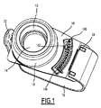
図1に図示する第1の実施形態に従う圧迫止血装置は、アプリケータ12が取り付けられた基部10を備え、そのアプリケータ12の末端のうちの1つは、パッド14を備える。腕輪16は基部10上に留められ、基部10を患者に一時的に固定することを可能にする。装置はまた、アプリケータ12を注入または穿刺ゾーンに向かって並進させるように、基部10に取り付けられると共にアプリケータ12と協働する回転式ボタン18を備える。
The compression hemostasis device according to the first embodiment illustrated in FIG. 1 includes a
図2aおよび2bに示す通り、基部10は、円弧状に湾曲した部分10bによって延在された平面部10aによって形成される。基部10の一般的な形状および寸法は、基部10を、患者の手首上の注射部位の周囲に人間工学的に位置決めすることができるように選択される。基部10は、照準孔20を形成する実質的に円形の凹部によって貫通され、照準孔20の中心は、平面部10aと曲面部10bとの間の境界を形成する区域の中間に位置する。
As shown in FIGS. 2a and 2b, the
照準孔20は、実質的に円筒形のフランジ22の基部を形成する。本説明の目的のため垂直となっているフランジ22の軸線X−Xは、基部10の平面部10aに対して垂直である。3つの線形ガイドウェイ23は、フランジ22の内表面全体に沿って軸線方向に延びる。ガイドウェイ23は対で等距離である。
The aiming
あるいは、ガイドウェイのうちの1つは、基部上のアプリケータに指標を付けるために、僅かに異なるか、またはずれることもあり得る。 Alternatively, one of the guideways can be slightly different or offset to index the applicator on the base.
貫通孔24は、フランジ22の周囲かつ基部に形成され、基部10の隣接部において延びる。貫通孔24は、フランジ22の外周全体に均一に分布する。フランジ22は、組立クリップ26の貫通孔24内を延びる。組立クリップ26は、軸線X−Xに対して平行して延びる。各組立クリップ26は、その遠位端にフランジ22の外側へ方向付けられた突起27を備える。各突起27は、フランジ22の外表面に対して突出する。
The through
基部10は、その曲面部10b内でありかつフランジ22の外周上に、調整ボタン用の半径方向補強用支持リブ28を備える。リブ28は平面部10aの高さに上がる。半径方向リブ28の平坦な上面は、基部10の平面部10aの平坦な上面と同じ平面に構成される。
The
基部10は、平面部10aと曲面部10bとの間の境界を形成する区域に重なり、軸線X−Xに対して、2つの直径方向に反対側に位置する支持部30を備える。各支持部30は鉛直方向に上がる。各支持部30の側面は、軸線X−Xを中心とする円弧を形成する。各支持部30は、弾性的に変形可能であり、その内側面上に、丸襞(un godron)または歯止め突起32を備える。
The
基部10の曲面部10bは、縦方向軸線X−Xとの中空半円筒形延在部34を備える。延在部34は、平面部10aの平面の高さに上がる。延在部34は、平面部10aと曲面部10bとの間に境界を形成する区域の長さと、実質的に等しい直径を有する。
The
基部10は、その曲面部10bの末端に、締付つまみ36を備える。基部10は、その平面部分10aの末端に、2つの留め金38を支持する延在部10cを備える。
The
図3aおよび3bに図示するように、アプリケータ12は支持部50を備える。支持部50は、外径d1を有する円筒形内管50a、および内径d2を有する円筒形外管50bによって形成される。2つの管50aおよび50bは互いに同軸であり、これらの基部によって接続している。外径d1は、基部10のフランジ22の内径と実質的に等しくなるように選択される。内径d2は、フランジ22の外径と実質的に等しくなるように選択される。ボタン18が作動する時に、管50aおよび管50bの長さは、アプリケータ12に対する所望の移動の振幅に応じて選択される。
As illustrated in FIGS. 3 a and 3 b, the
管50aは、第1の管50aの外面において縦方向に延びる3つの凹部52aを備える。凹部52aは、支持部50がフランジ22に取り付けられている時に、基部10のフランジ22のガイドウェイ23と協働するように、大きさおよび位置が決められる。管50aは、その自由端部において、パッド14を支持部50に固定するように、パッド14内に形成される円形凹部と協働する内側フランジ54aを備える。管50bの外面は、突出するねじ山56bを備える。
The
あるいは、管50bは、締め付け力を分散させてねじ締めの信頼性を高めるように、一方が他方内部に「嵌合」される2つのねじを有することができる。
Alternatively, the
パッド14は、透明な材料から作られる。パッド14の球面のドームベアリング形状は、すぐ近くに位置する他の静脈で静脈還流を遮断する危険性を減少させる一方で、患者の心地よさを最大化するように選択される。
The
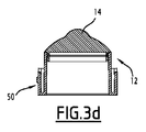
あるいは、パッドのベアリング形状は、橈骨動脈が位置する手首の溝に従うように、球面のドーム形状とは異なり、図3cおよび3dに示すように、具体的には長方形、特に半円筒形であってもよい。 Alternatively, the pad bearing shape is different from the spherical dome shape so as to follow the groove of the wrist where the radial artery is located, and is specifically rectangular, particularly semi-cylindrical, as shown in FIGS. 3c and 3d. Also good.
図4aおよび4bに図示するように、ボタン18は、実質的に円錐形の握り部材60bを伴い外向きに提供される円筒形内管60aによって形成され、操作者によるボタン14の取り扱いを容易にすることを可能にする。円筒管60aは、アプリケータ12の支持部50の外管50bの外径と実質的に等しい内径d3を有する。円筒管60aの内面は、アプリケータ12のねじ山または各ねじ山56bと協働することができる中空ねじピッチ62を備える。ボタン18の円筒形内壁はまた、突出する内スカート65をその基部に備え、その内スカート65の寸法および配設は、ボタン18が基部10に取り付けられると、その縦方向軸線に沿ったボタン18の並進を遮断するが、ボタン18をその同じ軸線の周囲を自由に回転するままにしておくよう、その組立クリップ26と協働するように選択される。切り欠き66は、複数の所定の安定的角度位置にボタンを維持することを可能にする停止手段を形成するために、ボタン18が基部10に取り付けられた時に、2つのリブ30の歯止め丸襞32と協働することができるように、円筒管60aの外表面全体に規則的に配設される。所望の場合には、2つの方向にボタンにかける力を分化するため、切り欠きは非対称であってもよい。
As illustrated in FIGS. 4a and 4b, the
ボタンの生産を容易にするために、スカート64および切り欠き66を備えるボタンの下部は、ボタンの残り部分に組み立てられる(例えば、接着または溶接される)、別の部品であってもよい。
To facilitate button production, the lower portion of the button with
ひとたび組み立てられると、アプリケータ12、ボタン18、および基部10は、ボタンの回転により透明パッドを並進させるように、スクリューとナットとのシステムによって接続される。スクリューとナットとのシステムのねじ山56b、62は、透明パッド14の直径の完全に外側に位置する。その結果として、注射部位上に位置する透明パッド14を通過する視界は隠されない。
Once assembled, the
図5に示すように、腕輪16は、その末端のうちの1つに2つの穴70を備え、その形状および配置により、基部10の留め金38との協働する際に、該端部を基部に固定することを可能にする。腕輪16の他方末端が複数の貫通孔72を備え、各貫通孔72が、該末端を基部10に固定するように、締付つまみ36と協働することができ、貫通孔の選択によって、患者の手首の周囲の腕輪16の締め付けを調整することを可能にする。
As shown in FIG. 5, the
あるいは、ボタン18は、基部10の孔中に直接ねじ込まれてもよく、アプリケータ12の近位端を、少なくともボタンへの並進の際に固定する。
Alternatively, the
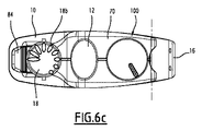
図6a、6b、および6cに示す、本発明による圧迫止血装置の第2の実施形態では、完全に透明であるアプリケータ12の近位端はプラテン70に固定され、その末端の一方がヒンジ72によって基部10に接続される。アプリケータは、基部の開口部73を軸線X−Xにおいて自由に通過する。プラテン70の末端の他方は、軸線X−Xと平行な孔74を有する。
In a second embodiment of the compression hemostasis device according to the invention shown in FIGS. 6 a, 6 b and 6 c, the proximal end of the
ボタン18は、角度基準18bが位置決めされる、ボタン18の頭部を形成する上部分18aを備える。ボタン18は、孔74を通過し、基部10の部分10bに固定されるナット75内にねじ込まれるねじ棒を形成する下部分18cを備える。
The
有利なことに、ナット75は、ユーザによって頭部18aにおけるボタンの縦方向軸線に沿って圧力が及ぼされる時に、その縦方向軸線に沿ってボタンの並進を十分可能にするよう変形することができるように構成され、それによって、ねじ締めによってするよりもボタン18を素早く動かすことが可能になる。この目的のために、ナット75のねじは、可撓性のあるストリップを備え、十分な弾性を提供する材料から作られることができる。
Advantageously, the
腕輪16は、可撓性のある腕輪80を備え、その末端の一方が、基部10の末端に固定され、腕輪80を伸縮させ、末端の他方が切り欠きゾーン82を備える。切り欠きゾーンは、ナット75が設けられた基部の近位端に提供される固締および固締解除レバー84と協働することができる。レバー84は、弾性的にその固締位置を取る傾向がある。
The
有利なことに、パッド14は、調整ボタンによって画定された位置にかかわらず、基部10に対して注射部位の方へ突出する。これによって、装置を配置する際に、全ての場合において、注射部位上に圧力が得られることが保証される。
Advantageously, the
有利なことに、本発明による装置は、配置および除去時間を記録するための手段を備えることができ、装置を取り扱う人が、装置を患者に配置した時間だけでなく、装置を除去しなくてはならない、または実際に除去した時間をも記録することを可能にする。有利なことに、配置および除去時間を記憶するための手段を、基部10上に位置決めすることができる。
Advantageously, the device according to the invention can be provided with means for recording the placement and removal times, so that the person handling the device has not only to remove the device but also to the time it has been placed on the patient. It also makes it possible to record the time that must not be removed or actually removed. Advantageously, means for storing placement and removal times can be positioned on the
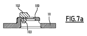
図7a、7b、および7cに図示する第1の実施形態では、配置および除去時間を記憶するための手段は、軸線X−Xに中心合わせされた弓形定規100を備え、その上に目盛101a、101bを有する。各目盛は、対応する時間に対する印に対応する。通常、図7cに示す通り、印は12から11まで進み、12時間から11時間まで進む時間スケールを表す。定規100は、第1の内側切り欠きガイドウェイ104を備える。組立クリップ103と共に提供されるピン102は、ガイドウェイ104に取り付けられる。ピン102はガイドウェイ104内を摩擦で移動し、内目盛101aの印のうちの1つに各々対応する複数の固定位置にピン102を維持することができる。定規100は、ポインタ106がその上を摺動する第2の切り欠き外側ガイドウェイ105を備える。ポインタ106は第2の切り欠きガイドウェイ内を摩擦で移動し、外目盛101bの印のうちの1つに各々対応する複数の固定位置にポインタ106を位置決めすることができる。2つのガイドウェイ内に提供される切り欠きは、あるいは、ピン102およびポインタ106の所定の安定位置を画定することができる。
In the first embodiment illustrated in FIGS. 7a, 7b, and 7c, the means for storing placement and removal times comprises an
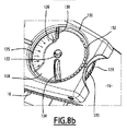
図8aおよび8bに図示する第2の実施形態では、配置および除去時間を記憶するための手段100は、軸122の周囲に回転自在に取り付けられた目盛り盤120を備える。時間基準が、例えば、1時間から24時間まで、目盛り盤120上に付けられている。目盛り盤の刻み付き周辺部123は、ユーザが目盛り盤120を回転できるように、ユーザに利用しやすくなっている。目盛り盤120は、目盛り盤120を覆う固定された不透明ディスク124によって、一部隠されている。不透明ディスク124はまた、不透明ディスク124によって覆われていない目盛り盤120の時間基準を指し示すことを可能にするように位置付けられた固定指標126を備える。不透明ディスク124によって可視に保たれた目盛り盤120の一部は丸い扇形ゾーン125に対応し、その扇形ゾーン125の寸法によって、固定指標126によって指し示される時間から8時間の時間範囲に対応する、目盛り盤120の時間基準の一群を見ることを可能にする。また、不透明ディスク124を覆う透明ディスク128が、軸122の周囲に回転自在に取り付けられる。透明ディスク128には、ユーザが、不透明ディスク124によって覆われていない目盛り盤120の1時間の印を識別することができるように配置されたポインタ130が設けられる。指標切り欠き132は、所定の複数の角度位置にわたって透明ディスク128の回転の指標を付けるように、不透明ディスク124および透明ディスク128上に位置決めされる。ユーザが透明ディスク128を容易に回転できるように、出っ張り134が、透明ディスク128の表面に位置決めされる。
In the second embodiment illustrated in FIGS. 8 a and 8 b, the
したがって、ユーザは患者への装置の前記配置時間を記憶して、目盛り盤120を回転させることによって、配置および実装時間に対応する目盛り盤120の印を、固定指標126によって指定することができる。ユーザは、透明ディスク128を回転させることによって、ポインタ130が、除去時間に対応する目盛り盤120の印を指定するまで、装置の除去時間を表示することができる。
Therefore, the user can specify the mark on the
あるいは、各実施形態では、時間インジケータのうちの一方および/または他方は、装置によって及ぼされる圧力の、行ったまたは行われるべき変更時間を示すことができる。 Alternatively, in each embodiment, one and / or the other of the time indicators can indicate the time at which the pressure exerted by the device has been or is to be changed.
図7a〜7cおよび8a〜8bに図示する記憶手段の2つの実施形態の組み合わせを、考慮することができる。 Combinations of the two embodiments of the storage means illustrated in FIGS. 7a-7c and 8a-8b can be considered.
あるいは、1時間目盛のみを備える装置を製作することも可能である。 Alternatively, it is also possible to produce a device with only an hour scale.
止血装置の第3の実施形態を、図9から14に示す。本装置は以下の点でのみ第1の実施形態と異なる。
― 基部10は、歯止め突起32を有する支持部30ではなく、基部10からボタン18に向かって突出する、2つの外側鉛直支持部200および1つの中間鉛直支持部210を備える。支持部210は装置の対称軸Pの垂直平面内に、支持部200はその平面の両側約30°に設置される。
― 延在部34は、基部10の平面部分10aの平面の上に上がり、円形であり、かつ平面Pに鉛直スロット212を有する。
― ボタン18は、握り部材60bではなく、内側円筒管60aのみを備え、その管60aは握り部材でもある。
― 円筒管60aは、切り欠き66または突出する内スカート64を有さないが、基部10へ方向付けられたその円筒管60aの部分に内側凹部214(図13および14)と、ボタン18から基部10に向かって鉛直に突出する少なくとも1つのタブ216(図9)とを備える。
A third embodiment of the hemostatic device is shown in FIGS. This apparatus is different from the first embodiment only in the following points.
The
The
The
第1の実施形態と比較して、止血装置の第3の実施形態はまた、固締システム218を備える。
Compared to the first embodiment, the third embodiment of the hemostatic device also comprises a
固締システム218は、リング220およびリバース防止ラッチ222を備える。リング220は、フランジ22と延在部34との間に位置する環状空間に配置される。
The
リング220は、内側円筒形リング224および外側歯付きクラウン226を備える。リング220は単一部品である。リング220は、例えば、ABSといった共重合体から作られる。リング224および歯付きクラウン226は、縦方向軸線X−Xの周囲に同軸に延びる。歯付きクラウン226は、リング224を囲む。リング224は、フランジ228を形成する一方で、歯付きクラウン226からボタン18に向かって鉛直に突出する。リング224は、基部10へ方向付けられたその部分に、突出する内スカート230を有し、その機能は、第1の実施形態のボタン18の対応するスカート64の機能に類似し、基部のクリップ26と協働することによって、スカート230は、縦方向軸線X−Xに沿ったリング220の並進を遮断するが、リング220を同じ軸線の周囲で自由に回転させる。
クラウン226は、基部10へ方向付けられたその末端セクションに、鉛直方向に方向付けられた鋸歯232を有する。歯232は、歯付きクラウン226の外周全体にわたって規則的に分布される。あるいは、歯232は、クラウン226の外周の180°または270°に対応する部分にわたって規則的に分布する。クラウン226は、基部の反対側に方向付けられたその部分に、少なくとも1つの切り欠き234を有する(図9)。
The
リング220のフランジ228は、ボタン18の円筒管60aの凹部214内において、摩擦締め付けに適合する外径を有する(図13および14)。リング220の切り欠きまたは各切り欠き234は、ボタン18のタブまたは各タブ216と協働するように適合する。このように、リング220は、軸線X−Xの周囲を回転するようにボタン18に固定される。
The
アプリケータ12およびその透明パッド14は、第1の実施形態のそれらと実質的に同一である。
The
あるいは、リング220およびボタン18は、接着または超音波溶接によって、互いに接続される。
Alternatively, the
リバース防止ラッチ222は、押しボタン236、固締歯止め238、弓形アーム240、および鉛直リブ242を備える(図10)。ラッチ222は単一部品で、POM等の重合体から作られる。
The
押しボタン236は、鉛直リブ242を介して歯止め238に接続する。遮断位置と非遮断位置との間を、軸線X−Xと平行して歯止め238を動かすように適合する。歯止め238は、基部の反対側に方向付けられたその部分中に、歯232の各々と協働することができるように、歯付きクラウン226の歯232のうちの1つの形状と相補的な形状を有する。歯止め238の基部10へ方向付けられた部分は、実質的に、弓形アーム240の中央部分に接続される。
The
遮断位置において、弓形アーム240は、歯止め238の両側において、軸線X−Xに垂直な平面で実質的に延びる(図12)。弓形アーム240は、アプリケータ12の内管50aの外径d1よりも大きいか、または等しい直径を有する円弧を描く。
In the blocking position, the
基部10の延在部34に存在する鉛直スロット212は、基部の平面部分10aの平面の上へ上がり、基部の反対側に開いている(図9)。スロット212は、押しボタン236が延在部34および歯止め238の外面に摺動して係止するために、かつ弓形アーム240が延在部34の内面に摺動して係止するために、ラッチ222の鉛直リブ242を受容するようにされた幅および長さを有する(図11)。その結果として、押しボタン236は、ユーザが利用しやすい一方、歯止め238および弓形アーム240はそうではない。
The
さらに(図11)、アーム240の末端部分は、基部の支持部200に覆いかぶさっている。
In addition (FIG. 11), the distal end portion of the
図11に図示する通り、リバース防止ラッチ222は、透明パッド14の直径の完全に外側に設置される。
As shown in FIG. 11, the
図12は、基部からボタン18に向かって突出する2つの外側鉛直支持部200および中間鉛直支持部210を示す。支持部210は、基部10から支持部200よりも低い高さまで突出する。支持部200、210は、歯止め238が遮断位置にある時に、弓形アーム240が外側支持部200にのみ係止するような高さであり、すなわち、歯止め238が遮断位置または非遮断位置にある時、アーム240は連続的に曲げられている。
FIG. 12 shows two outer
歯止め238が遮断位置にある時(図12)に、基部10の反対側に方向付けられた歯止めの一部は、歯付きクラウン226の歯232のうちの1つに係止している。歯232の傾斜により、歯止め238がこの遮断位置にある時に、リング220、ひいてはボタン18の軸線X−X回りの単方向回転が可能となる。この例では、ボタン18の回転が、注射部位の反対側にアプリケータ12およびパッド14を推進する回転の方向において遮断される一方、アプリケータ12およびパッド14を注射部位に向かって推進する反対方向の回転は、遮断されない。弓形アーム240のみが、支持部200に支持される。
When the
第1の前述の方向でボタン18の回転を可能にするために、すなわち、パッド14によって及ぼされる圧力を減少させるために、ユーザは、弓形アーム240によって及ぼされる弾性力に抗して押しボタン236を押し込む。これによって、歯止め238が非遮断位置にもたらされ(図14)、その際、歯付きクラウン226の歯232とは接触しない。その後、弓形アーム240は垂直に湾曲し、中間支持部210に当たる。歯止め238が非遮断位置にある時に、リング220、ひいてはボタン18は、軸線X−X回りに両方向に自由に回転する。それ故、その位置では、そのゾーンに及ぼされる圧力を減少させるように、注射部位の反対側にアプリケータ12およびパッド14を推進することが可能である。
In order to allow rotation of the
注射部位に及ぼされるパッド14の圧力を減少させるためには、リバース防止ラッチ222を非遮断位置に移動させ、対応する方向にボタン18を回転させることが重要である。これら2つの手技は、例えば、手首の周囲に止血装置を装着している患者が、1つの手で行うのは困難または不可能である。
In order to reduce the pressure of the
固締システム218は、注射部位上の透明パッド14を通る視界を隠さないように、パッド14の直径の完全に外側に位置決めされる。これにより、ユーザが、患者の注射部位に、本発明による止血装置を最適に位置付けることが可能になる。
The
Claims (15)
前記装置は、
・ 基部(10)と、
・ 前記基部(10)を前記患者に一時的に取り付けることができる支持手段(16)と、
・ 前記基部によって支 持されると共にパッド(14)が提供されるアプリケータ(12)と、
・ 前記アプリケータ(12)が、前記パッド(14)が前記注射部位に圧力を及ぼす位置へ、前記基部(10)に対して動くように、前記注射部位に向かって前記アプリケータ(12)を動かすことができる調整手段(18)と、
を備えるタイプのものである、
装置において、
前記基部(10)は、前記注射部位の反対側に、前記支持手段(16)によって支持される貫通照準孔(20)を備え、
前記パッド(14)は、透明でありかつ前記照準孔内で移動可能であり、
前記調整手段(18)は、前記パッド(14)の直径の完全に外側に位置している、
装置。 A compressions coagulation apparatus is Ru can stop bleeding caused by withdrawal of the syringe that fits into the injection site of a patient,
The device is
A base (10);
Support means (16) capable of temporarily attaching the base (10) to the patient;
An applicator (12) supported by the base and provided with a pad (14);
The applicator (12) is moved towards the injection site such that the pad (14) moves relative to the base (10) to a position where the pad (14) exerts pressure on the injection site. Adjustment means (18) which can be moved;
Of the type comprising
In the device
The base (10) comprises a through-sighting hole (20) supported by the support means (16) on the opposite side of the injection site,
The pad (14) is transparent and movable within the aiming hole;
It said adjusting means (18) is completely located outside of the front Kipa Tsu diameter de (14),
apparatus.
前記アプリケータ(12)、前記ボタン(18)、および前記基部(10)は、前記ボタン(18)の回転により、前記縦方向軸線(X−X)に沿って前記アプリケータ(12)の並進が引き起こされるように、スクリューとナットとのシステムによって接続され、
前記スクリューとナットとのシステムは、一体的に協働する前記アプリケータ(12)および前記ボタン(18)のねじ山(56b、62)を備え、
前記ねじ山(56b、62)は、前記パッド(14)の前記直径の完全な外側に位置している、
請求項1に記載の装置。 The adjusting means includes a button (18) attached to the base (10) so as to be rotatable about a longitudinal axis (XX) of the aiming hole (20),
The applicator (12), the button (18), and the base (10) are translated by the rotation of the button (18) along the longitudinal axis (XX). Connected by a screw and nut system, so that
The screw and nut system comprises the applicator (12) and the screw (56b, 62) of the button (18) cooperating together,
Said thread (56b, 62) is located fully outside the diameter of the front Kipa head (14),
The apparatus of claim 1.
請求項1または2に記載の装置。 The pad (14) projects relative to the base (10) towards the injection site, regardless of the position of the pad (14) defined by the adjusting means (18).
The apparatus according to claim 1 or 2.
請求項2に記載の装置。 The threads (56b, 62) are provided on the outer surface of the applicator (12) and the inner surface of the button (18).
The apparatus of claim 2 .
請求項2または4に記載の装置。 The base (10) and the button (18) comprise cooperating stop means (30, 32, 66) that allow the button to be maintained in a predetermined stable plurality of angular positions.
Apparatus according to claim 2 or 4 .
請求項2、4または5に記載の装置。 A clamping system (218) adapted to block rotation of the button (18) with respect to one of two directions of rotation of the button (18);
Apparatus according to claim 2, 4 or 5 .
請求項6に記載の装置。 The clamping system (218) is configured to block rotation of the button (18) in the direction of rotation that promotes translation of the applicator (12) opposite the injection site. Directional locking system,
The apparatus according to claim 6.
請求項6または7に記載の装置。 The clamping system (218) comprises a clamping member (238) that is movable between a blocking position and a non-blocking position.
Apparatus according to claim 6 or 7.
請求項8に記載の装置。 The fastening member (238) is movable parallel to the longitudinal axis (XX);
The apparatus according to claim 8.
請求項9に記載の装置。 The clamping member (238) is secured to an arcuate arm (240) supported on the base to ensure elastic return of the clamping member (238) toward its blocking position.
The apparatus according to claim 9.
請求項6〜10のいずれか1項に記載の装置。 It said locking system (218) is completely positioned outside the diameter of the front Kipa head (14),
The apparatus according to any one of claims 6 to 10.
請求項1〜11のいずれか1項に記載の止血装置。 The support means (16) comprises a bracelet fixed to the base (10),
The hemostatic device according to any one of claims 1 to 11.
請求項1〜12のいずれか1項に記載の装置。 Means (100) enabling to record the time when the device is placed on the patient or the time elapsed since that moment;
The device according to claim 1.
請求項1〜13のいずれか1項に記載の装置。 Means (100) enabling to record the time that the device must be removed from the patient or the time remaining until then
The apparatus according to claim 1.
請求項13または14のいずれか1項に記載の装置。 Means (100) enabling said pressure exerted by said device to be modified or to record the time that must be corrected or the time that has elapsed since then.
15. Apparatus according to any one of claims 13 or 14.
Applications Claiming Priority (3)
| Application Number | Priority Date | Filing Date | Title |
|---|---|---|---|
| FR0955412 | 2009-07-31 | ||
| FR0955412 | 2009-07-31 | ||
| PCT/FR2010/051577 WO2011012805A1 (en) | 2009-07-31 | 2010-07-26 | Compressive hemostatic device |
Publications (3)
| Publication Number | Publication Date |
|---|---|
| JP2013500753A JP2013500753A (en) | 2013-01-10 |
| JP2013500753A5 JP2013500753A5 (en) | 2013-09-12 |
| JP5722889B2 true JP5722889B2 (en) | 2015-05-27 |
Family
ID=41396340
Family Applications (1)
| Application Number | Title | Priority Date | Filing Date |
|---|---|---|---|
| JP2012522219A Active JP5722889B2 (en) | 2009-07-31 | 2010-07-26 | Compression hemostasis device |
Country Status (7)
| Country | Link |
|---|---|
| US (1) | US9107671B2 (en) |
| EP (1) | EP2459079B1 (en) |
| JP (1) | JP5722889B2 (en) |
| CN (1) | CN102548490B (en) |
| BR (1) | BR112012002253B1 (en) |
| ES (1) | ES2465041T3 (en) |
| WO (1) | WO2011012805A1 (en) |
Families Citing this family (22)
| Publication number | Priority date | Publication date | Assignee | Title |
|---|---|---|---|---|
| PL221369B1 (en) | 2011-10-28 | 2016-03-31 | Inst Kardiologii | Arterial tourniquet |
| EP2647359B1 (en) * | 2012-04-02 | 2014-03-19 | Karl Werkmeister, Medizinische Leibbinden Inh. Hans-Jürgen Germerodt | Compression bandage |
| CN103431887A (en) * | 2013-08-28 | 2013-12-11 | 武汉大学 | Blood vessel pressing device |
| USD733305S1 (en) | 2013-10-25 | 2015-06-30 | Medtronic Vascular, Inc. | Tissue compression apparatus |
| US9439827B2 (en) | 2013-10-25 | 2016-09-13 | Medtronic Vascular, Inc. | Tissue compression device with pressure indicator |
| CN103654906B (en) * | 2013-12-13 | 2015-12-09 | 杨玉辉 | Artery hemostatic instrument |
| US10092297B2 (en) | 2014-04-25 | 2018-10-09 | Medtronic Vascular, Inc. | Tissue compression device with fixation and tension straps |
| CN108451578B (en) * | 2015-01-09 | 2022-05-24 | 金珂生物医疗公司 | Dressing assembly and method of using same |
| FR3034304A1 (en) * | 2015-04-01 | 2016-10-07 | Fresenius Medical Care Deutschland Gmbh | HEMOSTATIC BRACELET |
| CN104856739B (en) * | 2015-04-28 | 2017-12-19 | 深圳市升昊科技有限公司 | Compression hemostasis device |
| CN104939888B (en) * | 2015-05-13 | 2017-06-30 | 深圳邦普医疗设备系统有限公司 | One kind classification rotary extrusion type spinning compression apparatus |
| US10363198B2 (en) * | 2015-08-26 | 2019-07-30 | Karen Salstein-Begley | Hand-pressing headache-relieving device |
| KR102359636B1 (en) | 2016-03-25 | 2022-02-09 | 티젯 메디컬 인코포레이티드 | Radial and Ulnar Compression Bands |
| US10588638B2 (en) | 2016-03-25 | 2020-03-17 | Tz Medical, Inc. | Radial compression band |
| FR3070850B1 (en) * | 2017-09-13 | 2019-09-27 | Hsbi | ARTERIAL HEMOSTATIC COMPRESSION DEVICE |
| US11298138B2 (en) | 2018-02-08 | 2022-04-12 | Tci Ms Ltd | Hemostatic device |
| US10918394B2 (en) | 2018-10-10 | 2021-02-16 | Oscor Inc. | Radial artery compression band having fine adjustment mechanism |
| PL3927251T3 (en) | 2019-02-19 | 2023-11-20 | Simplicardiac S.A. | Medical device for blood vessel compression |
| KR102211096B1 (en) * | 2019-03-18 | 2021-02-01 | 금오공과대학교 산학협력단 | Tourniquet |
| CN109846525A (en) * | 2019-04-16 | 2019-06-07 | 依奈德医疗技术(上海)有限公司 | Tourniquet |
| US11607228B2 (en) * | 2019-05-07 | 2023-03-21 | Cordis Us Corp. | Hemostasis pressure device |
| US11730487B2 (en) * | 2019-08-29 | 2023-08-22 | Mohammad Reza Rajebi | Vascular hemostasis system |
Family Cites Families (38)
| Publication number | Priority date | Publication date | Assignee | Title |
|---|---|---|---|---|
| US1322050A (en) * | 1919-11-18 | V tourniquet | ||
| US37156A (en) * | 1862-12-16 | Improvement in tourniquets | ||
| US760846A (en) * | 1903-10-15 | 1904-05-24 | Rupert L Border | Electric railway-switch. |
| GB191508900A (en) * | 1915-06-16 | 1916-06-15 | Heaton Clark Howard | An Improved Tourniquet. |
| US1218313A (en) * | 1916-08-28 | 1917-03-06 | Henry W Plummer | Surgical tourniquet. |
| US1281653A (en) * | 1917-10-06 | 1918-10-15 | Henry W Plummer | Tourniquet. |
| US1299860A (en) * | 1918-03-13 | 1919-04-08 | Henry W Plummer | Tourniquet. |
| US2113534A (en) * | 1936-10-24 | 1938-04-05 | Burroughs Wellcome Co | Tourniquet |
| US3050064A (en) * | 1959-10-22 | 1962-08-21 | Robert E Moore | Mechanical compress bandage |
| US4760846A (en) * | 1987-03-23 | 1988-08-02 | Freund Medical Products, Inc. | Radial artery clamp |
| DE69021119T2 (en) | 1989-04-28 | 1995-12-21 | Fujitsu Ltd | Imaging process using an electrically conductive composition. |
| US5139512A (en) * | 1990-10-18 | 1992-08-18 | Dreiling Leo D | Semiautomatic compress |
| US5695520A (en) * | 1995-12-05 | 1997-12-09 | Bruckner; James V. | Pressure-applying device having plate-supported pressure-applying body secured to flexible band |
| JP3087743B2 (en) | 1998-11-12 | 2000-09-11 | 住友電気工業株式会社 | Intermediate color LED |
| JP3087743U (en) * | 2002-02-04 | 2002-08-16 | 圭治 斎藤 | Tourniquet with timer for blood collection |
| DE60328343D1 (en) | 2002-07-15 | 2009-08-27 | Terumo Corp | Hemostatic device with inflatable balloon |
| JP3974467B2 (en) * | 2002-07-15 | 2007-09-12 | テルモ株式会社 | Hemostatic device |
| US20040092999A1 (en) * | 2002-09-28 | 2004-05-13 | Blazej Lojewski | Post-withdrawal venipuncture bruising control device and method |
| US7329270B2 (en) * | 2002-12-19 | 2008-02-12 | Radi Medical Systems Ab | Femoral compression device |
| US7637921B2 (en) * | 2003-03-04 | 2009-12-29 | Radi Medical Systems Ab | Femoral compression device with progressive pressure device |
| US6833001B1 (en) * | 2003-11-07 | 2004-12-21 | Richard C. C. Chao | Controllable tourniquet |
| US20050125025A1 (en) * | 2003-12-05 | 2005-06-09 | Marcel Rioux | Styptic device |
| AU2005269228B2 (en) * | 2004-08-04 | 2011-04-28 | Bradley Allan Ross | Adjustable tissue compression device |
| US7618384B2 (en) * | 2006-09-20 | 2009-11-17 | Tyco Healthcare Group Lp | Compression device, system and method of use |
| US8147417B2 (en) * | 2007-01-23 | 2012-04-03 | Ohk Medical Devices Ltd. | Tourniquet timer |
| US20080183207A1 (en) * | 2007-01-25 | 2008-07-31 | Horne John N | Tourniquet |
| CN201205292Y (en) * | 2008-03-13 | 2009-03-11 | 广州市名加医疗器械制造有限公司 | Radial artery compression hemostasis device |
| US8353927B2 (en) * | 2009-05-04 | 2013-01-15 | Merit Medical Systems, Inc. | Radial artery compression device |
| US8657850B2 (en) * | 2008-05-06 | 2014-02-25 | Merit Medical Systems, Inc. | Radial artery compression device |
| US20100113990A1 (en) * | 2008-11-03 | 2010-05-06 | Ti-Li Chang | Pneumatic device for cardiopulmonary resuscitation assist |
| DE202009005566U1 (en) * | 2009-02-05 | 2009-06-18 | Schröder, Jürgen, Dr.med.habil. | Compression apparatus to occlude the radial artery after angiography or intervention |
| US20100217202A1 (en) * | 2009-02-21 | 2010-08-26 | Clark Timothy W I | Device for achieving hemostasis at site of puncture wound |
| US8777982B2 (en) * | 2009-02-21 | 2014-07-15 | Forge Medical, Inc. | Device for achieving hemostasis |
| SE535901C2 (en) * | 2010-06-07 | 2013-02-12 | St Jude Medical Systems Ab | Femoral compression system and method for effecting compression with the femoral compression system |
| US20120046582A1 (en) * | 2010-08-17 | 2012-02-23 | The Seaberg Company, Inc. | Chest seal bandage and other medical devices for night use |
| CA2724866A1 (en) * | 2010-10-07 | 2012-04-07 | Jason Turner | Tourniquet with disposable absorbent element |
| US20120150215A1 (en) * | 2010-12-09 | 2012-06-14 | Juarez Industries | Junctional Bleed Device |
| US20130310628A1 (en) * | 2012-05-15 | 2013-11-21 | Ernest C. Chisena | Orthopaedic device and method of use for treating bone fractures |
-
2010
- 2010-07-26 BR BR112012002253A patent/BR112012002253B1/en active IP Right Grant
- 2010-07-26 US US13/387,516 patent/US9107671B2/en active Active
- 2010-07-26 CN CN201080038446.3A patent/CN102548490B/en active Active
- 2010-07-26 EP EP20100752867 patent/EP2459079B1/en active Active
- 2010-07-26 ES ES10752867T patent/ES2465041T3/en active Active
- 2010-07-26 JP JP2012522219A patent/JP5722889B2/en active Active
- 2010-07-26 WO PCT/FR2010/051577 patent/WO2011012805A1/en active Application Filing
Also Published As
| Publication number | Publication date |
|---|---|
| ES2465041T3 (en) | 2014-06-05 |
| BR112012002253B1 (en) | 2019-12-24 |
| CN102548490B (en) | 2015-05-13 |
| JP2013500753A (en) | 2013-01-10 |
| US20120191127A1 (en) | 2012-07-26 |
| EP2459079A1 (en) | 2012-06-06 |
| BR112012002253A2 (en) | 2016-06-14 |
| US9107671B2 (en) | 2015-08-18 |
| WO2011012805A1 (en) | 2011-02-03 |
| EP2459079B1 (en) | 2014-05-07 |
| CN102548490A (en) | 2012-07-04 |
Similar Documents
| Publication | Publication Date | Title |
|---|---|---|
| JP5722889B2 (en) | Compression hemostasis device | |
| US9743934B2 (en) | Radial artery compression device | |
| JP5520932B2 (en) | Radial artery compression device | |
| JP4382667B2 (en) | Medical device guide | |
| KR20130018783A (en) | Medical device | |
| JP2011528569A5 (en) | ||
| JP7367070B2 (en) | Medical device for blood vessel compression | |
| US9265919B2 (en) | Simplified medical inflation device with passive latch | |
| US11607228B2 (en) | Hemostasis pressure device | |
| US11864772B2 (en) | Tourniquet | |
| CN110974336B (en) | Contact-press type hemostatic bracelet | |
| US20070005090A1 (en) | Device and Method for Vascular Tamponade Following Percutaneous Puncture | |
| CA3124036C (en) | Method and apparatus for adjustable and simultaneous multiple vessel compression | |
| JP2001120659A (en) | Posture holding device for puncture needle | |
| US20230363767A1 (en) | Compression force indicator for achieving hemostasis | |
| CN211243620U (en) | Clinical B-type ultramicro-wound operation puncture positioner | |
| US20220126066A1 (en) | Force and load sensor and monitoring device for defining injury during ureteral access sheath deployment | |
| CN215458364U (en) | Intracardiac branch of academic or vocational study hemostasis compressor | |
| JP2003220066A (en) | Hemostatic device | |
| CN117204930A (en) | Puncture outfit for surgery | |
| US20140121687A1 (en) | Horizontal phlebectomy device |
Legal Events
| Date | Code | Title | Description |
|---|---|---|---|
| A521 | Request for written amendment filed |
Free format text: JAPANESE INTERMEDIATE CODE: A523 Effective date: 20130726 |
|
| A621 | Written request for application examination |
Free format text: JAPANESE INTERMEDIATE CODE: A621 Effective date: 20130726 |
|
| A977 | Report on retrieval |
Free format text: JAPANESE INTERMEDIATE CODE: A971007 Effective date: 20140314 |
|
| A131 | Notification of reasons for refusal |
Free format text: JAPANESE INTERMEDIATE CODE: A131 Effective date: 20140408 |
|
| A601 | Written request for extension of time |
Free format text: JAPANESE INTERMEDIATE CODE: A601 Effective date: 20140707 |
|
| A602 | Written permission of extension of time |
Free format text: JAPANESE INTERMEDIATE CODE: A602 Effective date: 20140714 |
|
| A521 | Request for written amendment filed |
Free format text: JAPANESE INTERMEDIATE CODE: A523 Effective date: 20141008 |
|
| TRDD | Decision of grant or rejection written | ||
| A01 | Written decision to grant a patent or to grant a registration (utility model) |
Free format text: JAPANESE INTERMEDIATE CODE: A01 Effective date: 20150224 |
|
| A61 | First payment of annual fees (during grant procedure) |
Free format text: JAPANESE INTERMEDIATE CODE: A61 Effective date: 20150326 |
|
| R150 | Certificate of patent or registration of utility model |
Ref document number: 5722889 Country of ref document: JP Free format text: JAPANESE INTERMEDIATE CODE: R150 |
|
| R250 | Receipt of annual fees |
Free format text: JAPANESE INTERMEDIATE CODE: R250 |
|
| R250 | Receipt of annual fees |
Free format text: JAPANESE INTERMEDIATE CODE: R250 |
|
| R250 | Receipt of annual fees |
Free format text: JAPANESE INTERMEDIATE CODE: R250 |
|
| R250 | Receipt of annual fees |
Free format text: JAPANESE INTERMEDIATE CODE: R250 |
|
| R250 | Receipt of annual fees |
Free format text: JAPANESE INTERMEDIATE CODE: R250 |
|
| R250 | Receipt of annual fees |
Free format text: JAPANESE INTERMEDIATE CODE: R250 |
|
| R250 | Receipt of annual fees |
Free format text: JAPANESE INTERMEDIATE CODE: R250 |