JP5721526B2 - Intake filter device for gas turbine - Google Patents
Intake filter device for gas turbine Download PDFInfo
- Publication number
- JP5721526B2 JP5721526B2 JP2011103667A JP2011103667A JP5721526B2 JP 5721526 B2 JP5721526 B2 JP 5721526B2 JP 2011103667 A JP2011103667 A JP 2011103667A JP 2011103667 A JP2011103667 A JP 2011103667A JP 5721526 B2 JP5721526 B2 JP 5721526B2
- Authority
- JP
- Japan
- Prior art keywords
- filter
- filter medium
- medium layer
- intake
- gas turbine
- Prior art date
- Legal status (The legal status is an assumption and is not a legal conclusion. Google has not performed a legal analysis and makes no representation as to the accuracy of the status listed.)
- Active
Links
Images


Landscapes
- Filtering Materials (AREA)
- Filtering Of Dispersed Particles In Gases (AREA)
Description
本発明は、ガスタービン設備の吸気系統に配置され、吸気中の粉塵を除去するガスタービン用吸気フィルタ装置に関する。 The present invention relates to an intake filter device for a gas turbine that is disposed in an intake system of a gas turbine facility and removes dust in the intake air.
ガスタービン設備は、吸気室および吸気ダクトを含む吸気系統と、圧縮機と、ガスタービン燃焼器と、ガスタービンと、排気系統とを備えている。例えば発電プラントに用いられるガスタービン設備は、吸気室より取り込んだ大気(吸気)を、吸気ダクトを介して圧縮機に供給し、ここで吸気を圧縮して高圧空気とする。さらにこの高圧空気を燃料とともにガスタービン燃焼器に供給して燃焼ガスを生成し、この燃焼ガスをガスタービンに供給して膨張させ、その際に発生する動力で発電機を駆動するようになっている。 The gas turbine equipment includes an intake system including an intake chamber and an intake duct, a compressor, a gas turbine combustor, a gas turbine, and an exhaust system. For example, in a gas turbine facility used in a power plant, air (intake air) taken from an intake chamber is supplied to a compressor through an intake duct, where the intake air is compressed into high-pressure air. Furthermore, this high-pressure air is supplied to the gas turbine combustor together with fuel to generate combustion gas, and this combustion gas is supplied to the gas turbine to be expanded, and the generator is driven by the power generated at that time. Yes.
一般に、大気中には、0.1μm〜10μmの範囲の粒子径分布を有する粉塵が存在しており、この粉塵がガスタービン設備内に取り込まれて圧縮機の翼に付着すると、流体抵抗が増加して出力ロスが発生し、結果として発電出力の低下を招くこととなる。
そこで、圧縮機の入口側に設けられる吸気室に、圧縮機に吸い込まれる吸気中の粉塵を除去する吸気フィルタ装置が収容されている。
In general, dust having a particle size distribution in the range of 0.1 μm to 10 μm exists in the atmosphere, and when this dust is taken into the gas turbine equipment and adheres to the blades of the compressor, the fluid resistance increases. As a result, an output loss occurs, resulting in a decrease in power generation output.
Therefore, an intake filter device for removing dust in the intake air sucked into the compressor is accommodated in an intake chamber provided on the inlet side of the compressor.
特許文献1(特開2011−7193号公報)等に開示されるように、通常、吸気フィルタ装置は複数段のフィルタから構成される。ここで、粉塵等の粒子の特性として、図8に示すように、粒子の付着力は該粒子の拡散力および慣性力に基づいて決定し、粒径0.3μmより小さい径に付着力の極小値が存在することが知られている。したがって、従来の吸気フィルタ装置では、付着力が小さく、高い粒子捕集率が期待できない微細粒子(0.1μm付近)をも確実に捕集するために、HEPAフィルタが使用されてきた。 As disclosed in Patent Document 1 (Japanese Patent Application Laid-Open No. 2011-7193) and the like, an intake filter device is usually composed of a plurality of stages of filters. Here, as shown in FIG. 8, as the characteristics of particles such as dust, the adhesion force of the particles is determined based on the diffusion force and inertial force of the particles, and the adhesion force is minimized to a diameter smaller than 0.3 μm. It is known that a value exists. Therefore, in the conventional intake filter device, a HEPA filter has been used in order to reliably collect fine particles (near 0.1 μm) that have a low adhesion force and cannot be expected to have a high particle collection rate.
例えば、従来多く用いられている吸気フィルタ装置は、粒子径が1μmの粉塵を30%程度除去できるプレフィルタと、その下流側に設置され、粒子径が1μm程度の粉塵を70%程度除去できる中性能フィルタと、さらにこの中性能フィルタの下流側に設置され、主に0.3μm程度の粉塵を99.97%以上除去できるHEPAフィルタとから構成される。また、より小型化を図った吸気フィルタ装置として、プレフィルタの下流側に、中性能フィルタとHEPAフィルタとが一体化して構成された複合HEPAフィルタを設けたものもある。上記したHEPAフィルタおよび複合HEPAフィルタ等の高性能フィルタは、フィルタの収容形態に対応してセパレータ式やミニプリーツ式等が用いられている。 For example, an air intake filter device that has been widely used in the past is a pre-filter that can remove about 30% of dust having a particle diameter of about 1 μm, and a pre-filter that is installed on the downstream side, and can remove about 70% of dust having a particle diameter of about 1 μm. It is composed of a performance filter and a HEPA filter that is installed on the downstream side of the medium performance filter and can mainly remove 99.97% or more of dust of about 0.3 μm. In addition, as an intake filter device that is further downsized, there is also a device in which a composite HEPA filter in which a medium performance filter and a HEPA filter are integrated is provided on the downstream side of the prefilter. For the high performance filters such as the HEPA filter and the composite HEPA filter described above, a separator type, a mini-pleat type, or the like is used in accordance with the filter accommodation form.
このような吸気フィルタ装置では、プレフィルタで吸気中の粗粒子を捕集し、ここで捕集しきれなかった中粒子〜微細粒子を高性能フィルタで捕集する。高性能フィルタを構成するHEPAフィルタは99.97%以上の粒子捕集率を有するため、圧縮機に吸い込まれる吸気を、クリーンルーム並みの超清浄空気とすることができる。
また、高性能フィルタとして、0.3μmの粒子に対して95%以上の粒子捕集率を有する準HEPAフィルタも広く一般に流通している。例えば、特許文献2(特開2010−255612号公報)には、この準HEPAフィルタをガスタービン用吸気フィルタ装置に用いる構成が開示されている。具体的には、2次フィルタとして準HEPAフィルタを設け、その下流側の3次フィルタとしてHEPAフィルタやULPAフィルタを設けた構成が記載されている。
In such an intake filter device, coarse particles in the intake air are collected by the pre-filter, and medium to fine particles that could not be collected here are collected by the high-performance filter. Since the HEPA filter constituting the high-performance filter has a particle collection rate of 99.97% or more, the intake air sucked into the compressor can be made into ultra-clean air equivalent to a clean room.
As a high-performance filter, a quasi-HEPA filter having a particle collection rate of 95% or more with respect to 0.3 μm particles is also widely distributed. For example, Patent Document 2 (Japanese Patent Application Laid-Open No. 2010-255612) discloses a configuration in which this quasi-HEPA filter is used in a gas turbine intake filter device. Specifically, a configuration is described in which a quasi-HEPA filter is provided as a secondary filter, and a HEPA filter or a ULPA filter is provided as a downstream third-order filter.
しかしながら、HEPAフィルタを用いた従来の高性能フィルタにおいては、粉塵による圧縮機の翼の汚れはほとんど発生せず、ガスタービンの出力低下は生じないが、フィルタの交換寿命が極めて短いという問題があった。通常、ガスタービン設備の運転時間の経過に伴ってフィルタへの粉塵の付着量が増加するため、フィルタ差圧が徐々に上昇する。フィルタ差圧が予め設定されたフィルタ交換差圧に達するとフィルタを交換するようにしている。一般には、ガスタービン設備では、フィルタを交換せずに少なくとも1年間連続運転(運転時間として約8760時間)できることが望まれている。ところが、上記したようなHEPAフィルタを用いると、粉塵の捕集率は高く維持できるもののフィルタの目詰まりが早期に発生し、定期検査前にガスタービン設備を停止してフィルタ交換しなければならないという事態が発生する。 However, in the conventional high-performance filter using the HEPA filter, the compressor blades are hardly contaminated by dust and the output of the gas turbine does not decrease, but there is a problem that the replacement life of the filter is extremely short. It was. Normally, the amount of dust attached to the filter increases as the operating time of the gas turbine equipment elapses, and therefore the filter differential pressure gradually increases. When the filter differential pressure reaches a preset filter exchange differential pressure, the filter is exchanged. In general, in a gas turbine facility, it is desired that the gas turbine equipment can be continuously operated (operating time is approximately 8760 hours) for at least one year without replacing the filter. However, when the HEPA filter as described above is used, the dust collection rate can be maintained high, but the filter is clogged early, and the gas turbine equipment must be stopped and the filter must be replaced before the periodic inspection. Things happen.
すなわち、ガスタービン設備に用いられる吸気フィルタ装置においては、大幅な出力低下を招かない程度の粉塵捕集率を維持しつつ、フィルタの交換寿命を長くすることが求められる。しかし、特許文献1等のように単にフィルタを複数段設けた構成では、これらの条件を満たすことは困難であった。
また、特許文献2等で用いられているHEPAフィルタは高価であり、この上頻繁にフィルタ交換をする必要が生じるため、吸気フィルタ装置のランニングコストが嵩むこととなる。
さらに、HEPAフィルタは圧損が大きく、一方ガスタービン設備は大量の圧縮空気を必要とするため、吸気室が大型化してしまうという問題もあった。また、0.001μm〜0.1μm程度の粒子径を有する僅かな量の粉塵の存在は、IC回路を生産するクリーンルームのような浄化空間を形成するためには有用であるが、ガスタービン用吸気フィルタ装置の翼の汚れによる圧縮効率低下には殆ど影響を及ぼさないため、HEPAフィルタは無用にコスト増加を招くものであった。
That is, in an intake filter device used for gas turbine equipment, it is required to extend the filter replacement life while maintaining a dust collection rate that does not cause a significant decrease in output. However, it is difficult to satisfy these conditions with a configuration in which a plurality of filters are simply provided as in
In addition, the HEPA filter used in
Furthermore, the HEPA filter has a large pressure loss, while the gas turbine equipment requires a large amount of compressed air, which causes a problem that the intake chamber becomes large. The presence of a small amount of dust having a particle size of about 0.001 μm to 0.1 μm is useful for forming a purification space such as a clean room for producing an IC circuit. The HEPA filter is unnecessarily increased in cost because it hardly affects the reduction in compression efficiency due to dirt on the blades of the filter device.
本発明の一態様では、上述の事情に鑑みてなされたものであり、ガスタービンの大幅な出力低下を招かない程度の粉塵捕集率を維持しつつ、フィルタの交換寿命を長くすることができるガスタービン用吸気フィルタ装置を提供することを目的とする。 One aspect of the present invention has been made in view of the above-described circumstances, and can increase the filter replacement life while maintaining a dust collection rate that does not cause a significant decrease in the output of the gas turbine. An object of the present invention is to provide an intake filter device for a gas turbine.
本発明の一態様に係るガスタービン用吸気フィルタ装置は、ガスタービン設備の吸気系統に配置されるガスタービン用吸気フィルタ装置であって、前記吸気系統の気流方向に複数段配置され、各段が一または複数のろ材層から形成されるフィルタを備え、前記複数段のフィルタを形成する全てのろ材層のうち最下流側のろ材層は、この上流側のろ材層より高い粒子捕集率を有し、且つ前記最下流側のろ材層の粒子捕集率は、粒径が0.3μmの粒子に対して95%以上99%以下であることを特徴とする。 An intake filter device for a gas turbine according to an aspect of the present invention is an intake filter device for a gas turbine arranged in an intake system of a gas turbine facility, and is arranged in a plurality of stages in the airflow direction of the intake system, and each stage is A filter formed of one or a plurality of filter medium layers, and among the filter medium layers forming the plurality of stages of filters, the most downstream filter medium layer has a higher particle collection rate than the upstream filter medium layer. In addition, the particle collection rate of the most downstream filter medium layer is 95% or more and 99% or less with respect to particles having a particle diameter of 0.3 μm.
このガスタービン用吸気フィルタ装置によれば、全てのろ材層の中で最下流側のろ材層が最も高い粒子捕集率を有するため、上流側のろ材層から順に、粗粒子から微細粒子へと段階的に効率よく粉塵を除去することができる。
また、最下流側のろ材層は、粒径が0.3μmの粒子に対して95%以上99%以下の粒子捕集率を有しているため、ガスタービンの大幅な出力低下を招かない程度の粉塵捕集率を維持しつつ、フィルタの交換寿命を長くすることが可能となる。ここで、最下流側のろ材層の粒子捕集率が95%未満であると、フィルタをすり抜けた粉塵が圧縮機の翼に付着し易くなり圧縮効率が低下し、ガスタービンの出力低下が顕著となる。一方、最下流側のろ材層の粒子捕集率が99%を超えると、フィルタが目詰まりし易くなりフィルタ交換寿命が短くなってしまう。したがって、最下流側のろ材層が上記した範囲の粒子捕集率を有することで、ガスタービンの出力を維持しつつフィルタ交換寿命を長くすることが可能となるものである。特に、フィルタ交換寿命が定期検査期間より長くなることで、ガスタービン設備の運転効率を向上させることができる。
さらに、最下流側のろ材層は、HEPAフィルタを用いる場合に比べて安価であるため、吸気フィルタ装置のコストを従来より削減することが可能となる。なお、最下流側のろ材層としては、準HEPAフィルタを用いることが好適である。
According to this gas turbine intake filter device, the most downstream filter medium layer has the highest particle collection rate among all the filter medium layers, so that from the upstream filter medium layer in order from coarse particles to fine particles. Dust can be efficiently removed step by step.
Moreover, since the filter medium layer on the most downstream side has a particle collection rate of 95% or more and 99% or less with respect to particles having a particle size of 0.3 μm, it does not cause a significant decrease in output of the gas turbine. It is possible to extend the replacement life of the filter while maintaining the dust collection rate. Here, when the particle collection rate of the filter medium layer on the most downstream side is less than 95%, the dust that has passed through the filter easily adheres to the blades of the compressor, the compression efficiency is lowered, and the output reduction of the gas turbine is remarkable. It becomes. On the other hand, if the particle collection rate of the filter medium layer on the most downstream side exceeds 99%, the filter is easily clogged and the filter replacement life is shortened. Therefore, the filter media layer on the most downstream side has a particle collection rate in the above-described range, so that the filter replacement life can be extended while maintaining the output of the gas turbine. In particular, the operating efficiency of the gas turbine equipment can be improved because the filter replacement life is longer than the periodic inspection period.
Furthermore, since the filter medium layer on the most downstream side is less expensive than the case where a HEPA filter is used, the cost of the intake filter device can be reduced as compared with the prior art. Note that a quasi-HEPA filter is preferably used as the most downstream filter medium layer.
一般に、空気中の粉塵は粒径1μm以下のものが30〜50%を占めている。上記した図8に示すように、粒径0.1μm〜0.3μm程度の空気中の粒子は、慣性力が小さく圧縮機翼の表面空気の流れに乗り、翼に付着しにくい。一方0.1μm以下の粒子は、慣性力は問題にならないほど小さいが、拡散力が大きいので翼に付着する可能性がある。しかし、0.1μm以下の粒子が大気中に含まれる量は極めて微量であるため、付着したとしても翼の表面粗度を増す作用は小さく、問題とはならない。ところが従来は、発電効率の低下に殆ど影響を及ぼさない0.1μm程度の粒子の捕集効率を上げるためにHEPAフィルタを用いていたため、フィルタ交換寿命の短縮とコスト増加を招いていた。そこで本発明者らは、従来用いられていた粒子捕集率99.97%のHEPAフィルタと、本構成における粒子捕集率95%以上99%以下のフィルタとを用いて発電端効率のデータを収集したところ、実際には本構成のフィルタの採用による微細粒子の捕集率低下は発電端効率にそれほど影響しないことが明らかになった。これは、微細粒子がもともと大気中に少ないことや、微細粒子は拡散現象が主で慣性力はほとんどないために回転中の圧縮機翼に付着するに至らないためと考えられる。したがって、上記したように、本構成のフィルタ構成を用いることにより、安価なコストで高い発電端効率を維持しつつ、フィルタ交換寿命を長くすることが可能となる。 Generally, dust in the air occupies 30 to 50% having a particle size of 1 μm or less. As shown in FIG. 8 described above, particles in the air having a particle size of about 0.1 μm to 0.3 μm have a small inertial force and ride on the flow of the surface air of the compressor blade, and are difficult to adhere to the blade. On the other hand, particles having a size of 0.1 μm or less are so small that the inertial force does not become a problem, but they may adhere to the wing due to the large diffusion force. However, since the amount of particles of 0.1 μm or less contained in the atmosphere is extremely small, even if it adheres, the effect of increasing the surface roughness of the blade is small and does not cause a problem. Conventionally, however, a HEPA filter has been used to increase the collection efficiency of particles of about 0.1 μm, which has little effect on the decrease in power generation efficiency, leading to a reduction in filter replacement life and an increase in cost. Therefore, the present inventors used the HEPA filter having a particle collection rate of 99.97% and a filter having a particle collection rate of 95% to 99% in the present configuration to generate power generation efficiency data. As a result of the collection, it has been clarified that the decrease in the collection rate of fine particles due to the adoption of the filter of the present configuration does not significantly affect the power generation end efficiency. This is presumably because there are few fine particles in the atmosphere from the beginning, and fine particles do not adhere to the rotating compressor blades because they are mainly diffused and have little inertial force. Therefore, as described above, by using the filter configuration of this configuration, it is possible to extend the filter replacement life while maintaining high power generation efficiency at a low cost.
上記ガスタービン用吸気フィルタ装置において、前記最下流側のろ材層は、粒径が0.3μmの粒子に対して97%以上98%以下の粒子捕集率を有することが好ましい。 In the gas turbine intake filter device, it is preferable that the most downstream filter medium layer has a particle collection rate of 97% or more and 98% or less with respect to particles having a particle diameter of 0.3 μm.
このように、最下流側のろ材層の粒子捕集率を97%以上とすることで、ガスタービンの出力をより一層高く維持することができ、且つ粒子捕集率を98%以下とすることで、フィルタ交換寿命をより一層長くすることが可能となる。 Thus, by setting the particle collection rate of the filter medium layer on the most downstream side to 97% or more, the output of the gas turbine can be maintained higher and the particle collection rate is set to 98% or less. Thus, the filter replacement life can be further extended.
上記ガスタービン用吸気フィルタ装置において、前記上流側のろ材層のうち前記最下流側のろ材層に隣り合うろ材層は、粒径が0.3μmの粒子に対して40%以上50%以下の粒子捕集率を有していてもよい。 In the gas turbine intake filter device, the filter medium layer adjacent to the most downstream filter medium layer among the upstream filter medium layers has a particle size of 40% to 50% with respect to a particle having a particle diameter of 0.3 μm. You may have a collection rate.
これにより、最下流側のろ材層の直前にて吸気中の煤塵のうち中粒子を確実に除去するとともに、0.3μm以下の粒径の微細粒子の一部を除去することができ、最下流側のろ材層まで到達する粉塵量を低減して最下流側のろ材層の目詰まり抑制に貢献する。したがって、フィルタ交換寿命をより長くすることが可能となる。なお、中間層は、上流側から下流側に向けて粗から密へと密度勾配を有する構成としてもよい。 As a result, it is possible to reliably remove medium particles from the dust in the intake air immediately before the filter medium layer on the most downstream side, and to remove some fine particles having a particle size of 0.3 μm or less. The amount of dust reaching the filter medium layer on the side is reduced, contributing to suppression of clogging of the filter medium layer on the most downstream side. Therefore, the filter replacement life can be extended. The intermediate layer may have a density gradient from coarse to dense from the upstream side to the downstream side.
上記ガスタービン用吸気フィルタ装置において、前記最下流側のろ材層と前記隣り合うろ材層とは、これらの粒子捕集率の中間の粒子捕集率を有する中間層を介して一体化されて最終段フィルタを形成していてもよい。 In the gas turbine intake filter device, the most downstream filter medium layer and the adjacent filter medium layer are integrated through an intermediate layer having a particle collection rate intermediate between these particle collection rates, and finally A stage filter may be formed.
このように、最下流側のろ材層とこれに隣り合うろ材層とが一体化されていることにより、それぞれを別個に設置する場合に比べて、吸気フィルタ装置の設置面積を低減することができる。また、最下流側のろ材層とこれに隣り合うろ材層とは、これらの中間の粒子捕集率を有する中間層を介して一体化されているため、最下流側のろ材層とこれに隣り合うろ材層との境界でろ材密度が急激に変化することがなく、この境界に粉塵が集中して堆積することを抑制できる。 As described above, since the most downstream filter medium layer and the filter medium layer adjacent thereto are integrated, the installation area of the intake filter device can be reduced as compared with the case where each filter medium layer is installed separately. . Further, since the most downstream filter medium layer and the filter medium layer adjacent thereto are integrated through an intermediate layer having an intermediate particle collection rate, the most downstream filter medium layer is adjacent to this. The density of the filter medium does not change abruptly at the boundary with the mating filter medium layer, and dust can be prevented from concentrating and accumulating at this boundary.
上記ガスタービン用吸気フィルタ装置において、前記最終段フィルタは、湿式抄紙法で製造される前記最下流側のろ材層と前記隣り合うろ材層とを半乾きの状態で一体化し、これを乾燥させることにより製造されるようにしてもよい。 In the gas turbine intake filter device, the last-stage filter is formed by integrating the most downstream filter medium layer manufactured by a wet papermaking method and the adjacent filter medium layer in a semi-dry state and drying the filter medium layer. You may make it manufacture by.
これにより、最下流側のろ材層とこれに隣り合うろ材層とを一体化したフィルタを容易に且つ安価に製造することが可能となる。 This makes it possible to easily and inexpensively manufacture a filter in which the most downstream filter medium layer and the filter medium layer adjacent thereto are integrated.
上記ガスタービン用吸気フィルタ装置は、前記最下流側のろ材層の主成分がガラス繊維であり、前記隣り合うろ材層の主成分が前記ガラス繊維より平均繊維径の大きいポリエステル繊維であってもよい。 In the gas turbine intake filter device, a main component of the filter medium layer on the most downstream side may be a glass fiber, and a main component of the adjacent filter medium layer may be a polyester fiber having an average fiber diameter larger than that of the glass fiber. .
一般に、フィルタのろ材層は一または複数種類の繊維を含み、この繊維を単独でまたはこれらの繊維を適宜混合した素材に、必要に応じて有機系バインダ、無機系バインダを単独でまたは混合して加えて製造される。本構成では、最下流側のろ材層に最も多く含まれる繊維成分がガラス繊維であり、これに隣り合うろ材層に最も多く含まれる繊維成分がポリエステル繊維である。これにより、最下流側のろ材層とこれに隣り合うろ材層とをそれぞれ容易に且つ安価に製造することが可能となる。 In general, the filter medium layer of the filter contains one or a plurality of types of fibers, and these fibers are used alone or in a material obtained by appropriately mixing these fibers, and an organic binder or an inorganic binder is used alone or mixed as necessary. In addition, it is manufactured. In this configuration, the fiber component contained most in the filter medium layer on the most downstream side is glass fiber, and the fiber component contained most in the filter medium layer adjacent thereto is polyester fiber. As a result, it is possible to easily and inexpensively manufacture the most downstream filter medium layer and the filter medium layer adjacent thereto.
本発明の一態様に係るガスタービン用吸気フィルタ装置は、ガスタービン設備の吸気系統に配置されるガスタービン用吸気フィルタ装置であって、An intake filter device for a gas turbine according to an aspect of the present invention is an intake filter device for a gas turbine disposed in an intake system of a gas turbine facility,
前記吸気系統の気流方向に複数段配置され、各段が一または複数のろ材層から形成されるフィルタを備え、A plurality of stages are arranged in the airflow direction of the intake system, and each stage includes a filter formed of one or a plurality of filter medium layers,
前記複数段のフィルタを形成する全てのろ材層のうち最下流側のろ材層は、この上流側のろ材層より高い粒子捕集率を有しており、Of all the filter media layers forming the multiple-stage filter, the most downstream filter media layer has a higher particle collection rate than this upstream filter media layer,
前記最下流側のろ材層と、前記上流側のろ材層のうち前記最下流側のろ材層に隣り合うろ材層とは、これらの粒子捕集率の中間の粒子捕集率を有する中間層を介して一体化されて最終段フィルタを形成していることを特徴とする。The most downstream filter medium layer and the filter medium layer adjacent to the most downstream filter medium layer among the upstream filter medium layers are intermediate layers having a particle collection rate intermediate between these particle collection rates. The final stage filter is formed by being integrated.
このガスタービン用吸気フィルタ装置によれば、全てのろ材層の中で最下流側のろ材層が最も高い粒子捕集率を有するため、上流側のろ材層から順に、粗粒子から微細粒子へと段階的に効率よく粉塵を除去することができる。According to this gas turbine intake filter device, the most downstream filter medium layer has the highest particle collection rate among all the filter medium layers, so that from the upstream filter medium layer in order from coarse particles to fine particles. Dust can be efficiently removed step by step.
また、最下流側のろ材層とこれに隣り合うろ材層とが一体化されていることにより、それぞれを別個に設置する場合に比べて、吸気フィルタ装置の設置面積を低減することができる。さらに、最下流側のろ材層とこれに隣り合うろ材層とは、これらの中間の粒子捕集率を有する中間層を介して一体化されているため、最下流側のろ材層とこれに隣り合うろ材層との境界でろ材密度が急激に変化することがなく、この境界に粉塵が集中して堆積することを抑制できる。Further, since the filter medium layer on the most downstream side and the filter medium layer adjacent thereto are integrated, the installation area of the intake filter device can be reduced as compared with the case where each is installed separately. Further, since the most downstream filter medium layer and the filter medium layer adjacent thereto are integrated through an intermediate layer having an intermediate particle collection rate, the most downstream filter medium layer and the filter medium layer adjacent to the intermediate filter layer are adjacent to each other. The density of the filter medium does not change abruptly at the boundary with the mating filter medium layer, and dust can be prevented from concentrating and accumulating at this boundary.
以上記載のように本発明の一態様によれば、複数段のフィルタのうち最下流側に位置する第2ろ材層が、全フィルタのろ材層の中で最も高い粒子捕集率を有するため、上流側のろ材層から順に、粗粒子から微細粒子へと段階的に効率よく粉塵を除去することができる。
また、最下流側のろ材層は、粒径が0.3μmの粒子に対して95%以上99%以下の粒子捕集率を有しているため、ガスタービンの大幅な出力低下を招かない程度の粉塵捕集率を維持しつつ、フィルタの交換寿命を長くすることが可能となる。ここで、第2ろ材層の粒子捕集率が95%未満であると、フィルタをすり抜けた粉塵が圧縮機動翼に付着し易くなり圧縮効率が低下し、ガスタービンの出力低下が顕著となる。一方、第2ろ材層の粒子捕集率が99%を超えると、フィルタが目詰まりし易くなりフィルタ交換寿命が短くなってしまう。したがって、第2ろ材層が上記した範囲の粒子捕集率を有することで、ガスタービンの出力を維持しつつフィルタ交換寿命を長くすることが可能となるものである。特に、フィルタ交換寿命が定期検査期間より長くなることで、ガスタービン設備の運転効率を向上させることができる。
さらに、この第2ろ材層は、HEPAフィルタを用いる場合に比べて安価であるため、吸気フィルタ装置のコストを従来より削減することが可能となる。
As described above, according to one aspect of the present invention , the second filter medium layer located on the most downstream side of the plurality of stages of filters has the highest particle collection rate among the filter medium layers of all the filters. Dust can be efficiently removed stepwise from coarse particles to fine particles in order from the upstream filter medium layer.
Moreover, since the filter medium layer on the most downstream side has a particle collection rate of 95% or more and 99% or less with respect to particles having a particle size of 0.3 μm, it does not cause a significant decrease in output of the gas turbine. It is possible to extend the replacement life of the filter while maintaining the dust collection rate. Here, if the particle collection rate of the second filter medium layer is less than 95%, the dust that has passed through the filter tends to adhere to the compressor blades, the compression efficiency is lowered, and the output reduction of the gas turbine becomes remarkable. On the other hand, if the particle collection rate of the second filter medium layer exceeds 99%, the filter is easily clogged and the filter replacement life is shortened. Therefore, when the second filter medium layer has a particle collection rate in the above-described range, it is possible to extend the filter replacement life while maintaining the output of the gas turbine. In particular, the operating efficiency of the gas turbine equipment can be improved because the filter replacement life is longer than the periodic inspection period.
Furthermore, since the second filter medium layer is less expensive than the case where a HEPA filter is used, the cost of the intake filter device can be reduced as compared with the prior art.
以下、図面を参照して本発明の好適な実施形態を例示的に詳しく説明する。但しこの実施形態に記載されている構成部品の寸法、材質、形状、その相対的配置等は特定的な記載がない限りは、この発明の範囲をそれに限定する趣旨ではなく、単なる説明例に過ぎない。
図1および図2を参照して、本発明の実施形態に係る吸気フィルタ装置の構成を説明する。ここで、図1は本発明の実施形態に係る吸気フィルタ装置の概略構成図で、図2は図1に示した最終段フィルタの概略構成図である。
Hereinafter, exemplary embodiments of the present invention will be described in detail with reference to the drawings. However, the dimensions, materials, shapes, relative arrangements, etc. of the components described in this embodiment are not intended to limit the scope of the present invention, but are merely illustrative examples, unless otherwise specified. Absent.
With reference to FIG. 1 and FIG. 2, the structure of the intake filter apparatus which concerns on embodiment of this invention is demonstrated. Here, FIG. 1 is a schematic configuration diagram of an intake filter device according to an embodiment of the present invention, and FIG. 2 is a schematic configuration diagram of a final stage filter shown in FIG.
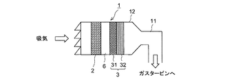
ガスタービン用吸気フィルタ装置1は、ガスタービン設備の吸気系統に配置される。吸気系統は、大気を吸気する吸気ダクト11と、吸気ダクト11上に形成された吸気室12とを含む。吸気フィルタ装置1は、吸気室12内に収容配置されていてもよい。大気中から吸気室12に吸い込まれた吸気は、吸気フィルタ装置1を通過することで吸気中の粉塵を除去された後、ガスタービン設備の圧縮機へ導かれるようになっている。
The gas turbine
この吸気フィルタ装置1は、吸気系統の気流方向に複数段配置されるフィルタ2、3を備える。複数段のフィルタ2、3は、各段が一または複数のろ材層から形成される。各ろ材層は、例えばポリエステル繊維、ポリアミド繊維、ポリオレフィン繊維、レーヨン繊維などの合成繊維の織布あるいは不織布、ガラス繊維の織布あるいは不織布、またはこれらを適宜混合した素材に、必要に応じて、有機系バインダ、無機系バインダを単独あるいは混合して加えて得られる混合バインダを適当量加えて、湿式抄紙法や乾式法、スパンボンド法、メルトブロー法などでシート状に形成し、その後これを乾燥して製造してもよい。
The
また、複数段のフィルタ2、3は、それぞれ異なる粒子捕集率を有する。具体的には、この吸気フィルタ装置1は、最も上流側に配置されるプレフィルタ2と、その下流側に配置される最終段フィルタ3とを有する。
これらのフィルタ2、3は、不図示のフィルタ枠内に収容された状態で接着剤等によりフィルタ枠に固定されて、このフィルタ枠ごと吸気室12の内壁に取り付けられる。このとき、これらのフィルタ2、3の収容形態は、セパレータ式であってもよいし、ミニプリーツ式であってもよい。
The plurality of stages of
These
プレフィルタ2は、好適には、粒径が0.3μmの粒子に対して10%以上20%以下の粒子捕集率を有する。このプレフィルタ2では、主に大径の粉塵を除去する。プレフィルタ2と最終段フィルタ3との間には、プレフィルタ2を通過した吸気の流速を均一にするための整流路6が設けられている。
The
最終段フィルタ3は、上流側に配置される第1ろ材層31と、該第1ろ材層31の下流側、すなわち複数段のフィルタを形成する全てのろ材層のうち最下流側に配置される第2ろ材層32とを含む。第1ろ材層31と第2ろ材層32とは隣り合って配置されており、これらの層が互いに接着されていてもよいし、フィルタ製造時点で一体化されて製造されていてもよい。
The
第1ろ材層31は、第2ろ材層32より粒子捕集率が低く、好適には、粒径が0.3μmの粒子に対して40%以上50%以下の粒子捕集率を有している。これにより、第2ろ材層32の直前にて吸気中の煤塵のうち中粒子を確実に除去するとともに、0.3μm以下の粒径の微細粒子の一部を除去することができ、第2ろ材層32まで到達する粉塵量を低減して第2ろ材層32の目詰まり抑制に貢献する。したがって、フィルタ交換寿命をより長くすることが可能となる。
The first
第2ろ材層32は、粒径が0.3μmの粒子に対して95%以上99%以下の粒子捕集率を有している。なお、第2ろ材層32としては、準HEPAフィルタを用いることが好適である。これにより、ガスタービンの大幅な出力低下を招かない程度の粉塵捕集率を維持しつつ、フィルタの交換寿命を長くすることが可能となる。
また、第1ろ材層31は主成分がポリエステル繊維であり、第2ろ材層32は主成分がガラス繊維であり、且つ第1ろ材層31のポリエステル繊維は第2ろ材層32のガラス繊維よりも平均繊維径が大きいことが好ましい。
The second
The first
さらにまた、図3に示すように、最終段フィルタ3は、第1ろ材層31と第2ろ材層32とが、これらの粒子捕集率の中間の粒子捕集率を有する中間層33を介して一体化されて形成されていてもよい。なお、中間層33は、上流側から下流側に向けて粗から密へと密度勾配を有する構成としてもよい。これにより、第1ろ材層31と第2ろ材層32とを別個に設置する場合に比べて、吸気フィルタ装置1の設置面積を低減することができる。また、第1ろ材層と第2ろ材層とは、これらの中間の粒子捕集率を有する中間層33を介して一体化されているため、第1ろ材層31と第2ろ材層32との境界でろ材密度が急激に変化することがなく、この境界に粉塵が集中して堆積することを抑制できる。
Furthermore, as shown in FIG. 3, the
このとき、最終段フィルタ3が、湿式抄紙法で製造される第1ろ材層31と第2ろ材層32とを半乾きの状態で一体化し、これを乾燥させることにより製造されることが好ましい。これにより、第1ろ材層31と第2ろ材層32とを一体化したフィルタを容易に且つ安価に製造することが可能となる。
At this time, it is preferable that the
ここで、図4乃至7を用いて、第2ろ材層32の粒子捕集率を上記範囲に設定した根拠を述べる。これらの図は、本発明者らが行った各種実験結果を示している。これらの実験で用いた吸気フィルタ装置1には、上記した図1に示すフィルタ構成を採用した。詳細には、上流側にプレフィルタ2として、粒径が0.3μmの粒子に対して10%以上20%以下の粒子捕集率を有するフィルタを配置し、その下流側に、第1ろ材層31と第2ろ材層32とが一体化された最終段フィルタ3を配置した吸気フィルタ装置1を用いた。最終段フィルタ3には、粒径が0.3μmの粒子に対して40%以上50%以下の粒子捕集率を有し、主体的にポリエステル繊維を含む第1ろ材層31と、粒径が0.3μmの粒子に対して95%以上99%以下の粒子捕集率を有し、主体的に上記のポリエステル繊維より繊維径が小であるガラス繊維を含む第2ろ材層32とを有するフィルタを用いた。なお、最終段フィルタ3は、上記した図3に示すように、湿式抄紙法で製造したものを用いた。
Here, the grounds for setting the particle collection rate of the second
図4は発電端効率またはフィルタ寿命に対する第2ろ材層の粒子捕集率を示す図である。図中、横軸は、粒径が0.3μmの粒子に対する第2ろ材層32の粒子捕集率η(%)を示す。なお、粒子捕集率ηは対数目盛上に表している。左側縦軸は発電端効率(%)を示し、右側縦軸はフィルタ交換寿命(Hr)を示す。また、このグラフ内で、実線は発電端効率曲線を示し、点線はフィルタ交換寿命曲線を示している。
FIG. 4 is a graph showing the particle collection rate of the second filter medium layer with respect to the power generation end efficiency or the filter life. In the figure, the horizontal axis indicates the particle collection rate η (%) of the second
同図に示すように、発電端効率は、粒子捕集率ηが低減するにしたがって低下する。これは、粒子捕集率が小さくなると第2ろ材層32を通過する粉塵量が増加して、フィルタをすり抜けた粉塵が圧縮機動翼に付着し易くなり圧縮効率が低下し、ガスタービンが出力低下するためである。特に、粒子捕集率が95%未満になると、ガスタービンの出力低下が顕著となる。これは、図5に示すように、粒子捕集率が95%未満である場合、圧縮機への粉塵流入量が急激に増加することが主要な原因と考えられる。なお、図5は、圧縮機への粉塵流入量に対する第2ろ材層の粒子捕集率を示す図である。
As shown in the figure, the power generation end efficiency decreases as the particle collection rate η decreases. This is because when the particle collection rate decreases, the amount of dust passing through the second
一方、フィルタ交換寿命は、粒子捕集率ηが増大するにしたがって低下する。これは、フィルタが目詰まりし易くなりフィルタ交換寿命が短くなってしまうためである。特に、粒子捕集率が99%を超えると、一般に定期検査期間として知られている1年を切ってしまい、定期検査前にフィルタ交換をしなければならなくなる。
図6は運転時間に対するフィルタ差圧の変化を示す図である。図中、実線は本実施形態に係る吸気フィルタ装置の寿命曲線を示し、破線は比較例として複合HEPAフィルタを使用した吸気フィルタ装置の寿命曲線を示す。同図に示すように、比較例の寿命曲線においては、運転時間が5000時間に達しないうちにフィルタ差圧が設定フィルタ差圧に到達してしまう。これに対して本実施形態の寿命曲線においては、運転時間が10000時間程度でフィルタ差圧が設定フィルタ差圧に到達し、一般的な定期検査期間である1年を超える。したがって、定期検査時期までフィルタ交換を行なわずに済み、発電効率を高く維持することが可能となる。
On the other hand, the filter replacement life decreases as the particle collection rate η increases. This is because the filter is easily clogged and the filter replacement life is shortened. In particular, when the particle collection rate exceeds 99%, it is less than one year, which is generally known as a periodic inspection period, and the filter must be replaced before the periodic inspection.
FIG. 6 is a diagram showing a change in the filter differential pressure with respect to the operation time. In the figure, a solid line shows a life curve of the intake filter device according to the present embodiment, and a broken line shows a life curve of an intake filter device using a composite HEPA filter as a comparative example. As shown in the figure, in the life curve of the comparative example, the filter differential pressure reaches the set filter differential pressure before the operation time reaches 5000 hours. On the other hand, in the life curve of the present embodiment, the filter differential pressure reaches the set filter differential pressure when the operation time is about 10,000 hours, and exceeds one year which is a general periodic inspection period. Therefore, it is not necessary to replace the filter until the periodic inspection time, and the power generation efficiency can be kept high.
上記したように本実施形態によれば、複数段のフィルタのうち最下流側に位置する第2ろ材層32が、全フィルタのろ材層の中で最も高い粒子捕集率を有するため、上流側のろ材層から順に、粗粒子から微細粒子へと段階的に効率よく粉塵を除去することができる。
また、第2ろ材層32は、粒径が0.3μmの粒子に対して95%以上99%以下の粒子捕集率を有しているため、ガスタービンの大幅な出力低下を招かない程度の粉塵捕集率を維持しつつ、フィルタの交換寿命を長くすることが可能となる。
さらに、この第2ろ材層32は、HEPAフィルタを用いる場合に比べて安価であるため、吸気フィルタ装置のコストを従来より削減することが可能となる。
As described above, according to the present embodiment, since the second
Moreover, since the second
Furthermore, since the second
さらにまた、本実施形態の吸気フィルタ装置1において、第2ろ材層32は、粒径が0.3μmの粒子に対して97%以上98%以下の粒子捕集率を有していることが好ましい。このように、第2ろ材層32の粒子捕集率を97%以上とすることで、ガスタービンの出力をより一層高く維持することができ、且つ粒子捕集率を98%以下とすることで、フィルタ交換寿命をより一層長くすることが可能となる。
Furthermore, in the
図7は本発明の実施形態の変形例に係る吸気フィルタ装置の概略構成図である。
この吸気フィルタ装置1’は、1次フィルタであるプレフィルタ2’と、第1ろ材層31’からなる2次フィルタ4と、第2ろ材層32’からなる3次フィルタ5とを有し、各フィルタがそれぞれ整流路7、8を介在して離間して配置されいる。ここで、プレフィルタ2’、第1ろ材層31’および第2ろ材層32’は、図1に示したプレフィルタ2、第1ろ材層31および第2ろ材層32と同様の構成を有する。
このように、第1ろ材層31’と第2ろ材層32’とが、整流路8を介在して離間して配置されていることにより、第2ろ材層32’に導入される吸気が整流されて均一化されるため部分的な目詰まりを防止できる。
FIG. 7 is a schematic configuration diagram of an intake filter device according to a modification of the embodiment of the present invention.
The
As described above, the first
1、1’ ガスタービン用吸気フィルタ装置
2、2’ プレフィルタ
3、3’ 最終段フィルタ
4 2次フィルタ
5 3次フィルタ
6、7、8 整流路
11 吸気ダクト
12 吸気室
31、31’ 第1ろ材層
32、32’ 第2ろ材層
33 中間層
DESCRIPTION OF
Claims (5)
前記吸気系統の気流方向に複数段配置され、各段が一または複数のろ材層から形成されるフィルタを備え、
前記複数段のフィルタを形成する全てのろ材層のうち最下流側のろ材層は、この上流側のろ材層より高い粒子捕集率を有し、且つ前記最下流側のろ材層の粒子捕集率は、粒径が0.3μmの粒子に対して95%以上99%以下であり、
前記上流側のろ材層のうち前記最下流側のろ材層に隣り合うろ材層は、粒径が0.3μmの粒子に対して40%以上50%以下の粒子捕集率を有しており、
前記最下流側のろ材層と前記隣り合うろ材層とは、これらの粒子捕集率の中間の粒子捕集率を有する中間層を介して一体化されて最終段フィルタを形成していることを特徴とするガスタービン用吸気フィルタ装置。 A gas turbine intake filter device disposed in an intake system of a gas turbine facility,
A plurality of stages are arranged in the airflow direction of the intake system, and each stage includes a filter formed of one or a plurality of filter medium layers,
Of all the filter media layers forming the multi-stage filter, the most downstream filter media layer has a higher particle collection rate than the upstream filter media layer, and the most downstream filter media layers collect particles. rates are state, and are particle size 99% or less 95% with respect to 0.3μm particles,
The filter medium layer adjacent to the most downstream filter medium layer among the upstream filter medium layers has a particle collection rate of 40% or more and 50% or less with respect to particles having a particle diameter of 0.3 μm,
The most downstream filter medium layer and the adjacent filter medium layer are integrated through an intermediate layer having a particle collection rate intermediate between these particle collection rates to form a final filter. An air intake filter device for a gas turbine.
前記吸気系統の気流方向に複数段配置され、各段が一または複数のろ材層から形成されるフィルタを備え、A plurality of stages are arranged in the airflow direction of the intake system, and each stage includes a filter formed of one or a plurality of filter medium layers,
前記複数段のフィルタを形成する全てのろ材層のうち最下流側のろ材層は、この上流側のろ材層より高い粒子捕集率を有しており、Of all the filter media layers forming the multiple-stage filter, the most downstream filter media layer has a higher particle collection rate than this upstream filter media layer,
前記最下流側のろ材層と、前記上流側のろ材層のうち前記最下流側のろ材層に隣り合うろ材層とは、これらの粒子捕集率の中間の粒子捕集率を有する中間層を介して一体化されて最終段フィルタを形成していることを特徴とするガスタービン用吸気フィルタ装置。The most downstream filter medium layer and the filter medium layer adjacent to the most downstream filter medium layer among the upstream filter medium layers are intermediate layers having a particle collection rate intermediate between these particle collection rates. An intake filter device for a gas turbine, which is integrated with each other to form a final stage filter.
Priority Applications (1)
| Application Number | Priority Date | Filing Date | Title |
|---|---|---|---|
| JP2011103667A JP5721526B2 (en) | 2011-05-06 | 2011-05-06 | Intake filter device for gas turbine |
Applications Claiming Priority (1)
| Application Number | Priority Date | Filing Date | Title |
|---|---|---|---|
| JP2011103667A JP5721526B2 (en) | 2011-05-06 | 2011-05-06 | Intake filter device for gas turbine |
Publications (2)
| Publication Number | Publication Date |
|---|---|
| JP2012233449A JP2012233449A (en) | 2012-11-29 |
| JP5721526B2 true JP5721526B2 (en) | 2015-05-20 |
Family
ID=47433988
Family Applications (1)
| Application Number | Title | Priority Date | Filing Date |
|---|---|---|---|
| JP2011103667A Active JP5721526B2 (en) | 2011-05-06 | 2011-05-06 | Intake filter device for gas turbine |
Country Status (1)
| Country | Link |
|---|---|
| JP (1) | JP5721526B2 (en) |
Families Citing this family (1)
| Publication number | Priority date | Publication date | Assignee | Title |
|---|---|---|---|---|
| JP6310133B1 (en) * | 2017-10-11 | 2018-04-11 | 株式会社ユー・イー・エス | Deodorizing filter |
Family Cites Families (4)
| Publication number | Priority date | Publication date | Assignee | Title |
|---|---|---|---|---|
| JP2001179028A (en) * | 1999-12-27 | 2001-07-03 | Tokyo Electric Power Co Inc:The | Air filter of washing regeneration type for gas turbine |
| JP4640895B2 (en) * | 2001-03-29 | 2011-03-02 | 日本無機株式会社 | High performance filter for gas turbine intake and gas turbine intake filter unit using the same |
| JP2005147034A (en) * | 2003-11-18 | 2005-06-09 | Mitsubishi Heavy Ind Ltd | Air filter for gas turbine, and washing method and washing system for the same, and service life prediction testing method for the same |
| JP5260331B2 (en) * | 2009-01-14 | 2013-08-14 | 三菱重工業株式会社 | A dust collection filter, a dust collection device, and a gas turbine intake device. |
-
2011
- 2011-05-06 JP JP2011103667A patent/JP5721526B2/en active Active
Also Published As
| Publication number | Publication date |
|---|---|
| JP2012233449A (en) | 2012-11-29 |
Similar Documents
| Publication | Publication Date | Title |
|---|---|---|
| EP2996792B1 (en) | Filtering chamber for gas turbines and method of maintenance thereof | |
| US7048501B2 (en) | Dust collecting filter, dust collecting device, and air intake device for gas turbine | |
| JP4640895B2 (en) | High performance filter for gas turbine intake and gas turbine intake filter unit using the same | |
| JP5650923B2 (en) | Filter cleaning system for gas turbine engine | |
| US9114347B2 (en) | Moisture separation system for high efficiency filtration | |
| JP5978460B2 (en) | AIR FILTER, AIR CLEANING APPARATUS HAVING THE AIR FILTER, AND ITS MANUFACTURING METHOD | |
| US8997450B2 (en) | Filter cartridge assembly for use with turbine engine systems | |
| JP2011190795A (en) | Depth-type filtration air filter material for suction and purification of gas turbine and compressor, and depth-type filtration air filter cartridge using the same | |
| JP6089199B2 (en) | Air filter and air purifier equipped with the air filter | |
| JP5721526B2 (en) | Intake filter device for gas turbine | |
| US20090301042A1 (en) | Gradient density engine intake filter media | |
| JP6506546B2 (en) | Gas turbine intake filter device | |
| JP2010255612A (en) | Intake filter unit for gas turbine | |
| WO2013121733A1 (en) | Air filter, air purifier provided with air filter, and method for producing air filter | |
| JP2010253455A (en) | Filter for air conditioner | |
| JP2021013896A (en) | Air filter unit | |
| WO2015070155A2 (en) | Assembly and method for a bag filter | |
| JP2009047150A (en) | Intake filter unit for gas turbine | |
| JP4667810B2 (en) | Gas turbine intake filter unit | |
| JP4555317B2 (en) | Gas turbine intake filter unit | |
| JP2011007193A (en) | Intake air filter unit for gas turbine | |
| JP2001263089A (en) | Filter unit for gas turbine intake | |
| JP2004150447A (en) | High performance filter for gas turbine inlet, and filter unit for gas turbine inlet using the same | |
| WO2015112605A1 (en) | Air filter with folded pleats | |
| JP2024081878A (en) | Oily smoke collection filter and ventilation system |
Legal Events
| Date | Code | Title | Description |
|---|---|---|---|
| A621 | Written request for application examination |
Free format text: JAPANESE INTERMEDIATE CODE: A621 Effective date: 20131010 |
|
| A977 | Report on retrieval |
Free format text: JAPANESE INTERMEDIATE CODE: A971007 Effective date: 20140512 |
|
| A131 | Notification of reasons for refusal |
Free format text: JAPANESE INTERMEDIATE CODE: A131 Effective date: 20140523 |
|
| A521 | Written amendment |
Free format text: JAPANESE INTERMEDIATE CODE: A523 Effective date: 20140717 |
|
| A711 | Notification of change in applicant |
Free format text: JAPANESE INTERMEDIATE CODE: A712 Effective date: 20150122 |
|
| TRDD | Decision of grant or rejection written | ||
| A01 | Written decision to grant a patent or to grant a registration (utility model) |
Free format text: JAPANESE INTERMEDIATE CODE: A01 Effective date: 20150227 |
|
| A61 | First payment of annual fees (during grant procedure) |
Free format text: JAPANESE INTERMEDIATE CODE: A61 Effective date: 20150324 |
|
| R150 | Certificate of patent or registration of utility model |
Ref document number: 5721526 Country of ref document: JP Free format text: JAPANESE INTERMEDIATE CODE: R150 |
|
| S533 | Written request for registration of change of name |
Free format text: JAPANESE INTERMEDIATE CODE: R313533 |
|
| R350 | Written notification of registration of transfer |
Free format text: JAPANESE INTERMEDIATE CODE: R350 |