JP5720295B2 - Sleep evaluation apparatus and display method in sleep evaluation apparatus - Google Patents
Sleep evaluation apparatus and display method in sleep evaluation apparatus Download PDFInfo
- Publication number
- JP5720295B2 JP5720295B2 JP2011035705A JP2011035705A JP5720295B2 JP 5720295 B2 JP5720295 B2 JP 5720295B2 JP 2011035705 A JP2011035705 A JP 2011035705A JP 2011035705 A JP2011035705 A JP 2011035705A JP 5720295 B2 JP5720295 B2 JP 5720295B2
- Authority
- JP
- Japan
- Prior art keywords
- unit
- period
- level
- sleep
- sleep state
- Prior art date
- Legal status (The legal status is an assumption and is not a legal conclusion. Google has not performed a legal analysis and makes no representation as to the accuracy of the status listed.)
- Active
Links
- 230000007958 sleep Effects 0.000 title claims description 146
- 238000011156 evaluation Methods 0.000 title claims description 18
- 238000000034 method Methods 0.000 title claims description 16
- 238000012360 testing method Methods 0.000 claims description 11
- 238000001514 detection method Methods 0.000 claims description 5
- 238000005259 measurement Methods 0.000 description 33
- 238000004891 communication Methods 0.000 description 21
- 238000010586 diagram Methods 0.000 description 15
- 230000000875 corresponding effect Effects 0.000 description 13
- 230000000241 respiratory effect Effects 0.000 description 13
- 230000029058 respiratory gaseous exchange Effects 0.000 description 11
- 238000012937 correction Methods 0.000 description 8
- 230000008859 change Effects 0.000 description 6
- 230000006870 function Effects 0.000 description 6
- NJPPVKZQTLUDBO-UHFFFAOYSA-N novaluron Chemical compound C1=C(Cl)C(OC(F)(F)C(OC(F)(F)F)F)=CC=C1NC(=O)NC(=O)C1=C(F)C=CC=C1F NJPPVKZQTLUDBO-UHFFFAOYSA-N 0.000 description 3
- 238000012545 processing Methods 0.000 description 3
- 230000007704 transition Effects 0.000 description 3
- 230000036541 health Effects 0.000 description 2
- 230000008569 process Effects 0.000 description 2
- 210000004556 brain Anatomy 0.000 description 1
- 230000002596 correlated effect Effects 0.000 description 1
- 238000006073 displacement reaction Methods 0.000 description 1
- 230000000694 effects Effects 0.000 description 1
- 230000001747 exhibiting effect Effects 0.000 description 1
- 230000012447 hatching Effects 0.000 description 1
- 238000010191 image analysis Methods 0.000 description 1
- 238000007689 inspection Methods 0.000 description 1
- 230000007246 mechanism Effects 0.000 description 1
- 238000012986 modification Methods 0.000 description 1
- 230000004048 modification Effects 0.000 description 1
- 230000000737 periodic effect Effects 0.000 description 1
- 208000019116 sleep disease Diseases 0.000 description 1
Images


Classifications
-
- A—HUMAN NECESSITIES
- A61—MEDICAL OR VETERINARY SCIENCE; HYGIENE
- A61B—DIAGNOSIS; SURGERY; IDENTIFICATION
- A61B5/00—Measuring for diagnostic purposes; Identification of persons
- A61B5/48—Other medical applications
- A61B5/4806—Sleep evaluation
-
- A—HUMAN NECESSITIES
- A61—MEDICAL OR VETERINARY SCIENCE; HYGIENE
- A61B—DIAGNOSIS; SURGERY; IDENTIFICATION
- A61B5/00—Measuring for diagnostic purposes; Identification of persons
- A61B5/103—Detecting, measuring or recording devices for testing the shape, pattern, colour, size or movement of the body or parts thereof, for diagnostic purposes
- A61B5/11—Measuring movement of the entire body or parts thereof, e.g. head or hand tremor, mobility of a limb
- A61B5/1118—Determining activity level
-
- A—HUMAN NECESSITIES
- A61—MEDICAL OR VETERINARY SCIENCE; HYGIENE
- A61B—DIAGNOSIS; SURGERY; IDENTIFICATION
- A61B5/00—Measuring for diagnostic purposes; Identification of persons
- A61B5/48—Other medical applications
- A61B5/4806—Sleep evaluation
- A61B5/4809—Sleep detection, i.e. determining whether a subject is asleep or not
-
- A—HUMAN NECESSITIES
- A61—MEDICAL OR VETERINARY SCIENCE; HYGIENE
- A61B—DIAGNOSIS; SURGERY; IDENTIFICATION
- A61B5/00—Measuring for diagnostic purposes; Identification of persons
- A61B5/48—Other medical applications
- A61B5/4806—Sleep evaluation
- A61B5/4812—Detecting sleep stages or cycles
-
- A—HUMAN NECESSITIES
- A61—MEDICAL OR VETERINARY SCIENCE; HYGIENE
- A61B—DIAGNOSIS; SURGERY; IDENTIFICATION
- A61B5/00—Measuring for diagnostic purposes; Identification of persons
- A61B5/48—Other medical applications
- A61B5/4806—Sleep evaluation
- A61B5/4815—Sleep quality
-
- A—HUMAN NECESSITIES
- A61—MEDICAL OR VETERINARY SCIENCE; HYGIENE
- A61B—DIAGNOSIS; SURGERY; IDENTIFICATION
- A61B5/00—Measuring for diagnostic purposes; Identification of persons
- A61B5/0002—Remote monitoring of patients using telemetry, e.g. transmission of vital signals via a communication network
- A61B5/0015—Remote monitoring of patients using telemetry, e.g. transmission of vital signals via a communication network characterised by features of the telemetry system
- A61B5/002—Monitoring the patient using a local or closed circuit, e.g. in a room or building
-
- A—HUMAN NECESSITIES
- A61—MEDICAL OR VETERINARY SCIENCE; HYGIENE
- A61B—DIAGNOSIS; SURGERY; IDENTIFICATION
- A61B5/00—Measuring for diagnostic purposes; Identification of persons
- A61B5/103—Detecting, measuring or recording devices for testing the shape, pattern, colour, size or movement of the body or parts thereof, for diagnostic purposes
- A61B5/11—Measuring movement of the entire body or parts thereof, e.g. head or hand tremor, mobility of a limb
- A61B5/113—Measuring movement of the entire body or parts thereof, e.g. head or hand tremor, mobility of a limb occurring during breathing
-
- A—HUMAN NECESSITIES
- A61—MEDICAL OR VETERINARY SCIENCE; HYGIENE
- A61B—DIAGNOSIS; SURGERY; IDENTIFICATION
- A61B5/00—Measuring for diagnostic purposes; Identification of persons
- A61B5/68—Arrangements of detecting, measuring or recording means, e.g. sensors, in relation to patient
- A61B5/6887—Arrangements of detecting, measuring or recording means, e.g. sensors, in relation to patient mounted on external non-worn devices, e.g. non-medical devices
-
- A—HUMAN NECESSITIES
- A61—MEDICAL OR VETERINARY SCIENCE; HYGIENE
- A61B—DIAGNOSIS; SURGERY; IDENTIFICATION
- A61B5/00—Measuring for diagnostic purposes; Identification of persons
- A61B5/74—Details of notification to user or communication with user or patient ; user input means
- A61B5/742—Details of notification to user or communication with user or patient ; user input means using visual displays
Landscapes
- Health & Medical Sciences (AREA)
- Life Sciences & Earth Sciences (AREA)
- Heart & Thoracic Surgery (AREA)
- Medical Informatics (AREA)
- Physics & Mathematics (AREA)
- Veterinary Medicine (AREA)
- Biophysics (AREA)
- Pathology (AREA)
- Engineering & Computer Science (AREA)
- Biomedical Technology (AREA)
- Public Health (AREA)
- General Health & Medical Sciences (AREA)
- Molecular Biology (AREA)
- Surgery (AREA)
- Animal Behavior & Ethology (AREA)
- Oral & Maxillofacial Surgery (AREA)
- Physiology (AREA)
- Dentistry (AREA)
- Anesthesiology (AREA)
- Measurement Of The Respiration, Hearing Ability, Form, And Blood Characteristics Of Living Organisms (AREA)
Description
この発明は睡眠評価装置および睡眠評価装置における表示方法に関し、特に、非侵襲で被測定者の睡眠状態を評価する睡眠評価装置および睡眠評価装置における表示方法に関する。 The present invention relates to a sleep evaluation apparatus and a display method in the sleep evaluation apparatus, and more particularly to a sleep evaluation apparatus for non-invasively evaluating a sleep state of a measurement subject and a display method in the sleep evaluation apparatus.
健康維持にとって睡眠は重要な要素であり、睡眠パターンを知ることは健康維持の観点から重要である。 Sleep is an important factor for maintaining health, and knowing sleep patterns is important from the viewpoint of maintaining health.
代表的な睡眠パターンの測定方法としては睡眠ポリグラフ(PSG)検査が挙げられる。睡眠ポリグラフ検査とは、睡眠障害の診断に用いられる検査の一つであって、被測定者の脳波を測定し、その変化に基づいて睡眠の深さを確認するものである。 A typical sleep pattern measuring method is a polysomnography (PSG) test. The polysomnography test is one of the tests used for diagnosing sleep disorders, and measures the brain wave of the measurement subject and confirms the depth of sleep based on the change.
簡易な方法としては、たとえば特開2009−160001号公報(以下、特許文献1)や特許第4103925号公報(以下、特許文献2)に開示されているように、寝具の下に配置されるセンサを用いて被測定者の体動の時間変化を計測し、当該計測結果に基づいて、被測定者の睡眠状態やその質等を判断する方法が挙げられる。 As a simple method, for example, as disclosed in Japanese Patent Application Laid-Open No. 2009-160001 (hereinafter referred to as Patent Document 1) and Japanese Patent No. 4103925 (hereinafter referred to as Patent Document 2), a sensor disposed under the bedding. There is a method of measuring the time change of the body movement of the person to be measured using, and judging the sleep state of the person to be measured and the quality thereof based on the measurement result.
しかしながら、睡眠ポリグラフ検査では電極や多数のセンサを被測定者の頭部に装着する必要があるために被測定者の負担が大きいばかりでなく、検査中に測定者が待機する必要もあることから測定者の負担も大きいという問題があった。 However, in polysomnographic testing, it is necessary to wear electrodes and a large number of sensors on the subject's head, which not only places a heavy burden on the subject, but also requires the measurer to wait during the examination. There was a problem that the burden on the measurer was large.
一方で、特許文献1、2に開示されている方法は睡眠ポリグラフ検査よりも被測定者への侵襲性は低いために被測定者の負担は睡眠ポリグラフ検査よりは小さいと言えるが、寝具の下に配置されるセンサを用いるものであるために寝具の制約があり、やはり、被測定者の負担はある程度はあるという問題があった。
On the other hand, since the methods disclosed in
さらに、特許文献1、2に開示されている方法では睡眠状態と覚醒状態との判別のみなされて、その結果が出力されるものであるため、専門知識を有しないユーザは睡眠の状態がどのような状態であったかを理解し難いという問題があった。
Furthermore, in the methods disclosed in
本発明はこのような問題に鑑みてなされたものであって、被測定者への負担を軽減して当該被測定者の睡眠状態のレベルを把握しやすく提示することのできる睡眠評価装置および睡眠評価装置における表示方法を提供することを目的の一つとしている。 This invention is made in view of such a problem, Comprising: The sleep evaluation apparatus which can reduce the burden on a to-be-measured person, and can present the level of the to-be-measured person's sleep state easily, and sleep One of the objects is to provide a display method in the evaluation apparatus.
上記目的を達成するために、本発明のある局面に従うと、睡眠評価装置は、被験者の身体の動きを検出する体動検出手段と、体動検出手段の検出結果に基づいて、所定期間の被験者の睡眠状態のレベルを時間軸に沿ったグラフで表示装置に表示させる表示データを生成する演算手段とを備える。演算手段は、体動検出手段の検出結果に基づいて、単位期間ごとの被験者の睡眠状態を判別する第1の判別手段と、第1の判別手段で判別された単位期間ごとの睡眠状態に基づいて、単位期間が所定数連続してなる所定期間の睡眠状態のレベルを判別する第2の判別手段と、所定期間の睡眠状態のレベルに応じて、当該所定期間ごとの表示態様を決定する決定手段と、所定期間の睡眠状態のレベルを表示態様で表わした表示データを生成する生成手段とを含む。 To achieve the above object, according to an aspect of the present invention, the sleep evaluation device includes a body motion detecting means that detect the movement of the subject's body, based on the detection result of the body motion detecting means, the predetermined time period and a arithmetic means that generates display data to be displayed on the display device in the graph along the level of the sleeping state of the subject on the time axis. Calculating means, based on the detection result of the body motion detecting means, a first discriminating means you determine the sleep state of the subject per unit time, the sleeping state of each discriminated unit period in the first discriminating means Based on the second discrimination means for discriminating the level of the sleep state of the predetermined period in which the predetermined number of unit periods are continuous, and the display mode for each predetermined period is determined according to the level of the sleep state of the predetermined period that includes determined and constant means and generate unit that generates a display data expressed in the display mode the level of the sleeping state for a predetermined period.
好ましくは、表示データは、時間軸に沿って所定期間を表わすセグメントを連続して表示させるデータであって、決定手段は、所定期間の睡眠状態のレベルに応じて、当該所定期間を表わすセグメントの表示態様を決定する。 Preferably, the display data is data for continuously displaying a segment representing the predetermined period along the time axis, and the determining means determines the segment representing the predetermined period according to the level of the sleep state of the predetermined period. The display mode is determined.
より好ましくは、決定手段は、所定期間を表わすセグメントの色を、睡眠状態のレベルに応じた色に決定する。 More preferably, the determining means determines the color of the segment representing the predetermined period to a color corresponding to the sleep state level.
より好ましくは、表示データは、時間軸に沿って、時間軸に交差する睡眠状態のレベルを表わす軸に応じて所定期間を表わすセグメントを連続して表示させるデータであって、決定手段は、所定期間を表わすセグメントの睡眠状態のレベルを表わす軸の方向の表示位置を、睡眠状態のレベルに応じた位置に決定する。 More preferably, the display data is data for continuously displaying a segment representing a predetermined period in accordance with an axis representing a sleep state level crossing the time axis along the time axis. The display position in the direction of the axis representing the sleep state level of the segment representing the period is determined to be a position corresponding to the sleep state level.
好ましくは、第1の判別手段は、単位期間における体動の大きさおよび/または体動の周期性に基づいて単位期間の被験者の睡眠状態を判別する。 Preferably, the first determination unit determines the sleep state of the subject in the unit period based on the magnitude of body movement and / or the periodicity of the body movement in the unit period.
好ましくは、第1の判別手段は、単位期間における体動の大きさおよび/または体動の周期性に基づいて単位期間の被験者の睡眠状態を判別する判別手段と、単位期間の被験者の睡眠状態を、単位期間に隣接する単位期間の被験者の睡眠状態の判別結果に基づいて補正する補正手段とを含む。 Preferably, the first determination means, the body motion in a unit period and determine by means you determine the sleep state of the subject unit period based on the size and / or periodicity of the body motion, the unit period of the subject sleep state, and a compensation unit that be corrected on the basis of the discrimination result of the subject's sleep state unit period adjacent to the unit period.
好ましくは、所定期間は一日のうちの予め規定された時間帯の属する期間であって、生成手段は、複数日についての時間帯の被験者の睡眠状態のレベルを、同一時間軸で表示させる表示データを生成する。 Preferably, the predetermined period is a period to which a predetermined time period of one day belongs, and the generation unit displays the level of the sleep state of the subject in the time period for a plurality of days on the same time axis. Generate data.
本発明の他の局面に従うと、表示方法は、センサからの、被験者の身体の動きを検出したセンサ信号に基づいて、所定期間の被験者の睡眠状態のレベルを時間軸に沿ったグラフで表示装置に表示させる、睡眠評価装置における表示方法であって、センサ信号の入力を受付けるステップと、センサ信号に基づいて、単位期間ごとの被験者の睡眠状態を判別するステップと、単位期間ごとの睡眠状態の判別結果に基づいて、単位期間が連続してなる所定期間の睡眠状態のレベルを判別するステップと、所定期間の睡眠状態のレベルに応じて、当該所定期間ごとの表示態様を決定するステップと、所定期間の睡眠状態のレベルを前記表示態様で表わした表示データを生成するステップとを備える。 According to another aspect of the present invention, a display method displays a level of a subject's sleep state for a predetermined period as a graph along a time axis based on a sensor signal from a sensor that detects the movement of the subject's body. A display method in the sleep evaluation device, the step of accepting the input of the sensor signal, the step of determining the sleep state of the subject for each unit period based on the sensor signal, and the sleep state for each unit period A step of determining a sleep state level for a predetermined period of continuous unit periods based on the determination result; a step of determining a display mode for each predetermined period according to the sleep state level of the predetermined period; Generating display data representing the level of the sleep state for a predetermined period in the display mode.
この発明によると、被測定者への負担を軽減して当該被測定者の睡眠状態のレベルを取得することができる。さらに、その睡眠状態のレベルを把握しやすく提示することができる。 According to the present invention, it is possible to reduce the burden on the measurement subject and obtain the level of the measurement subject's sleep state. Furthermore, the level of the sleep state can be presented easily.
以下に、図面を参照しつつ、本発明の実施の形態について説明する。以下の説明では、同一の部品および構成要素には同一の符号を付してある。それらの名称および機能も同じである。 Embodiments of the present invention will be described below with reference to the drawings. In the following description, the same parts and components are denoted by the same reference numerals. Their names and functions are also the same.
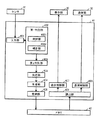
<外観>
図1は、本実施の形態にかかる睡眠レベル測定装置(以下、測定装置と略する)100の外観の具体例を示す図である。また、図2は測定装置100の側面を表わした概略図であり、図3は、斜め上方から見た外観の概略図である。
<Appearance>
FIG. 1 is a diagram showing a specific example of the appearance of a sleep level measuring apparatus (hereinafter, abbreviated as a measuring apparatus) 100 according to the present embodiment. FIG. 2 is a schematic diagram showing a side surface of the
図1〜図3を参照して、測定装置100は、一例として、台座に対して直方体またはその角が丸みを帯びて処理された縦長の形状の筐体が立てられた外観を有する。
1 to 3, as an example, measuring
図1を参照して、台座表面には操作用のボタン(あるいはボタン群)10が配備され、台座に立てられた筐体の表面には表示部20とが配備される。また、その筐体内部には、センサ30と、制御部40とが内包される。
Referring to FIG. 1, an operation button (or button group) 10 is provided on the surface of the pedestal, and a
以降の説明において、筐体の表示部20が設けられた面を測定装置100の正面とも称する。
In the following description, the surface of the housing on which the
測定装置100は無線または有線での通信を行なうための通信部50を有する。通信部50は、一例として、筐体の、台座と逆側の端部よりに設けられる。そして、通信部50を用いて、パーソナルコンピュータ(以下、PC)や携帯電話機などの表示装置200に接続されて、表示装置200に対して表示データを出力する。
The
<ハードウェア構成>
図4は、測定装置100のハードウェア構成の具体例を示すブロック図である。
<Hardware configuration>
FIG. 4 is a block diagram illustrating a specific example of the hardware configuration of the
図4を参照して、ボタン10、センサ30、表示部20、および通信部50は、いずれも、制御部40に接続される。
Referring to FIG. 4,
ボタン10はユーザに操作されることによる操作信号を制御部40に対して出力する。
センサ30は体動センサ31を含み、センサ信号を制御部40に対して出力する。体動センサ31としては、好適にはドップラーセンサが用いられる。以降の説明では、体動センサ31がドップラーセンサであるものとする。他には、超音波センサや赤外線センサが用いられてもよい。
The
The
ドップラーセンサである体動センサ31は、図示しない、測定用の電波を出力するための出力部と、受信部とを有する。受信部は、出力部から出力した電波のうち被測定体表面から反射した電波を受信し、出力した電波からの周波数の変化に応じたセンサ信号を出力する。
The
なお、体動を検出する機構として体動センサ31に替えてカメラを備えて、制御部40において画像解析を行なうことで体動を検出してもよい。
Note that a body motion may be detected by providing a camera instead of the
制御部40は、全体制御を行なうためのCPU41と、CPU41で実行されるプログラムなどを記憶するためのメモリ42とを含む。制御部40は、CPU41がメモリ42に記憶されている表示用のプログラムを実行し、入力された操作信号およびセンサ信号を用いて演算を実行することで、後述する睡眠のレベルを算出し、睡眠のレベルを表示するための表示データを生成する。
制御部40は、表示データに基づく画面表示を表示部20に行なうための表示制御を実行する。さらに、表示データを表示装置200に対して通信部50から送信するための通信制御を実行する。
The
通信部50は、たとえば赤外線通信やBluetooth(登録商標)を利用した通信などの無線通信で、直接、表示装置200と通信するものであってもよいし、インターネット接続機能を有して、インターネットを介して表示装置200と通信するものであってもよい。
The
さらに、通信部50は無線LAN(Local Area Network)のサーバ機能を有して、無線LAN接続でアクセスした表示装置200に対して、たとえばHTML(Hyper Text Markup Language)などのマークアップ言語で表現された後述の表示データを送信するようにしてもよい。
Further, the
<使用例>
図5は、測定装置100の使用例を説明する図である。
<Usage example>
FIG. 5 is a diagram for explaining an example of use of the measuring
図5を参照して、測定装置100は、一例として就寝中の被測定者の近傍(たとえば枕元)に設置される。その状態で測定動作が行なわれることで、ドップラーセンサである体動センサ31から電波が出力される。
Referring to FIG. 5,
体動センサ31から出力された電波は就寝中の被測定者の主に胸元、肩、などの辺りに到達し、そこからの反射波の周波数の変化がセンサ信号として制御部40に出力される。制御部40は、この周波数の変化に基づいて、就寝中の被測定者の胸の動きや寝返りなどの体動を検出し、その検出結果に基づいて睡眠のレベルを判定する。
The radio wave output from the
<機能構成>
図6は、測定装置100において睡眠のレベルを判定するための機能構成の具体例を示すブロック図である。図6に表わされる各機能は、主に、CPU41がメモリ42に記憶されるプログラムを実行することによってCPU41上に形成されるものであるが、少なくとも一部が電気回路などのハードウェア構成によって形成されてもよい。
<Functional configuration>
FIG. 6 is a block diagram illustrating a specific example of a functional configuration for determining the sleep level in the
図6を参照して、測定装置100は、センサ30からのセンサ信号の入力を受付けるための入力部401と、そのセンサ信号に基づいて単位期間の睡眠状態を判別するための第1判別部402と、単位期間ごとの判別結果に基づいて、当該単位期間が所定数連続してなる一定期間の睡眠状態のレベルを判別するための第2判別部409と、睡眠状態のレベルに基づいて当該一定期間の表示態様を決定するための決定部403と、決定された表示態様に基づいて睡眠のレベルを表示する表示データを生成するための生成部404と、表示データをメモリ42に格納する処理を実行するための格納部405と、メモリ42から表示データを読み出すための読出部406と、読み出された表示データを表示部20に表示させる処理を実行するための表示制御部407と、通信部50で表示装置200に対して送信する処理を実行するための通信制御部408とを含む。
Referring to FIG. 6,
図6の例では、入力部401が、センサ30からのセンサ信号を直接受け取るものとしているが、センサ信号はメモリ42の所定領域に一時的に記憶され、入力部401は表示のための動作を行なう際にそこから読み出すようにしてもよい。
In the example of FIG. 6, the
<睡眠のレベルの判別方法>
ここで、第2判別部409での睡眠のレベルの判別方法について説明する。
<Determination method of sleep level>
Here, a method for determining the sleep level in the
図7は、ドップラーセンサである体動センサ31からのセンサ信号の具体例を示す図である。図7は、体動センサからの搬送波と被測定者の表面からの反射波との位相の変位量に関係する電圧値の時間変化を表わしている。
FIG. 7 is a diagram illustrating a specific example of a sensor signal from the
図7を参照して、センサ信号で表わされる波形は、被測定者の呼吸に伴う体動(胸の動き)を表わす波形(以下、呼吸波形とも称する)と、寝返りなどの呼吸以外の体動を表わす波形(以下、体動波形とも称する)とを含む合成波である。 Referring to FIG. 7, the waveform represented by the sensor signal includes a waveform representing body movement (chest movement) accompanying breathing of the measurement subject (hereinafter also referred to as a breathing waveform) and body movement other than breathing such as turning over. Is a synthesized wave including a waveform (hereinafter also referred to as a body motion waveform).
図8(A)および図8(B)は、図7に表わされた波形から分離された呼吸波形および体動波形の具体例を示す図である。 FIG. 8 (A) and FIG. 8 (B) is a diagram showing a specific example of isolated respiratory waveform and the body motion waveform from the waveform represented in Figure 7.
安定した睡眠状態であるときのヒトの呼吸波形は周期性を有する。従って、呼吸波形の周期性が所定範囲内である場合、すなわち、その周期のばらつきが所定範囲内であるときには、概ね、安定した睡眠状態であると言える。 The human respiration waveform when in a stable sleep state has periodicity. Therefore, when the periodicity of the respiratory waveform is within a predetermined range, that is, when the variation in the cycle is within the predetermined range, it can be said that the sleep state is generally stable.
また、安定した睡眠状態であるとき、寝返りなどの呼吸以外の体動は生じ難い。従って、体動波形の振幅が所定範囲内であるときには概ね安定した睡眠状態であると言え、所定範囲以上となった場合には体動が生じているために安定した睡眠状態ではないと言える。 In addition, when the patient is in a stable sleep state, body movements other than breathing such as turning over are unlikely to occur. Therefore, when the amplitude of the body motion waveform is within the predetermined range, it can be said that the sleep state is almost stable, and when it exceeds the predetermined range, it can be said that the body motion has occurred and the sleep state is not stable.
従って、ある期間については、その期間における呼吸波形の周期性や呼吸以外の体動の大きさに基づいて被測定者が安定した睡眠状態にあるか否かを判別することができる。なお、この例では、呼吸波形と体動波形との両波形を用いて判別するものとしているが、少なくとも一方の波形のみを用いてもよい。 Therefore, for a certain period, it can be determined whether or not the measurement subject is in a stable sleep state based on the periodicity of the respiratory waveform in that period and the magnitude of body movements other than respiration. In this example, the determination is made using both the respiratory waveform and the body movement waveform, but at least one of the waveforms may be used.
図6に示されるように、第1判別部402は、判別部4021と補正部4022とを含む。
As shown in FIG. 6, the
判別部4021は、図7に示された入力されたセンサ信号に基づく波形を、図8(A)および図8(B)に示される呼吸波形と体動波形とに分離する。そして、それぞれの波形に基づいて、予め規定された単位期間(図7の期間t1,t2,t3,t4,t5)ごとに、被測定者が安定した睡眠状態にあるか否かを判別する。ここでの単位期間は、たとえば30秒や1分程度が挙げられる。すなわち、呼吸波形の単位期間t1における周期のばらつきが予め設定されているしきい値よりも小さい場合には、単位期間t1における呼吸波形に周期性が見られると判断する。また、体動波形の単位期間t1における振幅が予め設定されているしきい値よりも大きいか小さいかを判断する。
The discriminating
そして、判別部4021は、単位期間t1における呼吸波形に周期性があり、かつ体動波形の振幅がしきい値よりも小さい場合に、単位期間t1の当該被測定者の睡眠状態を睡眠状態(S)であると判別する。一方、判別部4021は、単位期間t1における呼吸波形に周期性がなく、かつ体動波形の振幅がしきい値よりも大きい場合に、単位期間t1の当該被測定者の睡眠状態を覚醒状態(W)であると判別する。なお、いずれか一方の条件のみが満たされている場合、つまり、単位期間t1における呼吸波形に周期性があるか、または、体動波形の振幅がしきい値よりも小さい場合に、覚醒状態と判別するようにしてもよい。
Then, when the respiratory waveform in the unit period t1 is periodic and the amplitude of the body motion waveform is smaller than the threshold value, the
図9(A)は、判別部4021での判別結果の具体例を示す図である。図9(A)に示されるように、判別部4021は、入力されたセンサ信号に基づく波形の単位期間ごとに、安定した睡眠状態であるか覚醒状態であるかを判別する。
FIG. 9A is a diagram illustrating a specific example of the determination result in the
しかしながら、睡眠状態において体動が生じたり、覚醒状態において体動がなく呼吸が安定していたりする単位期間が生じる場合もある。また、被測定者以外の移動物からの反射波を受信して、その結果、体動波形にノイズが生じる場合もある。そこで、好ましくは、補正部4022は、隣接する単位期間の判別結果に応じて、当該単位期間の判別結果を補正する。
However, there may be a unit period in which body movement occurs in the sleep state or there is no body movement in the awake state and the breathing is stable. Moreover, the reflected wave from moving objects other than a to-be-measured person is received, As a result, noise may arise in a body motion waveform. Therefore, preferably, the
一例として、図9(B)に、図9(A)に示された判別結果の補正の具体例を示す。図9(A)および図9(B)を参照して、補正部4022は、同一の判別結果である単位期間の連続数が所定数以下であり、かつ、当該判別結果と反対の判別結果である単位期間がこの連続した単位期間の前後に所定数以上連続している場合、その連続した単位期間の判別結果を、反対の判別結果となるように補正する。
As an example, FIG . 9B shows a specific example of correction of the discrimination result shown in FIG . With reference to FIG. 9A and FIG. 9B, the
具体的には、判別部4021は図9(A)の単位期間t7について覚醒状態(W)と判別しているが、覚醒状態(W)と判別された単位期間は単位期間t7に対して連続しておらず(すなわち、連続数が1であり)、かつ、単位期間t7の前後において睡眠状態(S)と判別された単位期間がある程度連続している。判別結果が逆の同様の状態は単位期間t13についても見られる。
Specifically, the
仮に、対象とする単位期間の判別結果の連続数のしきい値(第1のしきい値)を2、その前後の単位期間の判別結果の連続数のしきい値(第2のしきい値)を2とすると、単位期間t7については、覚醒状態(W)と判別された単位期間の連続数1が上記第1のしきい値よりも小さく、かつ、単位期間t7の前後の判別結果の逆の単位期間の連続数3が上記第2のしきい値よりも大きい、という条件を満たしている。従って、補正部4022は、単位期間t7の判別結果を、反対の判別結果である睡眠状態(S)となるように補正する。
Suppose that the threshold value of the number of consecutive determination results of the target unit period (first threshold value) is 2, and the threshold value of the number of continuous determination results of the unit periods before and after that (second threshold value). ) Is 2, for the unit period t7, the
同様にして、補正部4022は、単位期間t13の判別結果も、反対の判別結果である覚醒状態(W)となるように補正する。
Similarly, the
次に、第2判別部409は、上記単位期間が連続してなる一定期間について、各単位期間の判別結果に基づいて、睡眠のレベルを判別する。ここでの一定期間は、たとえば5分や10分程度が挙げられる。
Next, the 2nd discrimination |
ここで、睡眠のレベルとは、呼吸の安定具合と、体動の有無、連続性とから定義される睡眠の状態のレベルを指す。具体例として、
レベル1:体動がなく、呼吸が安定している睡眠状態、
レベル2:単発的な体動がある睡眠状態、
レベル3:連続的な体動がある睡眠状態、
レベル4:連続的な体動が続く覚醒状態、
レベル5:完全な覚醒状態、
などが挙げられる。
Here, the level of sleep refers to the level of sleep state defined by the degree of stability of breathing, the presence or absence of body movement, and continuity. As a specific example,
Level 1: Sleep state with no movement and stable breathing,
Level 2: Sleep state with single body movement,
Level 3: Sleep state with continuous body movement,
Level 4: Awakened state with continuous body movement,
Level 5: Full awake state,
Etc.
第2判別部409は、各レベルの判定値として、一定期間を構成する各単位期間の判別結果の連続数や、比率を記憶しておく。一例として、図13は上記レベル1の象徴的なセンサ信号の示す波形の具体例、図14は上記レベル2の象徴的なセンサ信号の示す波形の具体例、図15および図16は上記レベル3の象徴的なセンサ信号の示す波形の具体例、図17は上記レベル4の象徴的なセンサ信号の示す波形の具体例、図18は上記レベル5の象徴的なセンサ信号の示す波形であって特に入床時のセンサ信号の示す波形、および図19は上記レベル5の象徴的なセンサ信号の示す波形であって特に離床時のセンサ信号の示す波形を表わす図である。第2判別部409は、これらセンサ信号の示す波形に表わされた判別結果の連続数や、比率を、各レベルの判定値として予め記憶しておく。そして、図9(C)は、各一定期間ごとの睡眠のレベルの判定結果の具体例を表わす図である。すなわち、図9(B)および図9(C)を参照して、第2判別部409は、上記一定期間を構成する単位期間の連続について、判定結果の連続数と記憶している判定値とを比較すること、および、判定結果の比率と判定値とを比較すること、によって、当該一定期間の睡眠のレベルを判別する。
The
<表示例>
測定装置100では、ある時間帯について、その時間帯に属する上記一定期間ごとに、当該一定期間を表わすセグメントを睡眠のレベルに応じた表示態様とし、当該セグメントを時間経過に沿って並べて表示する。
<Display example>
In the measuring
図10は、睡眠のレベルの表示の第1の具体例を示す図である。
図10を参照して、第1の例として、上記一定期間を表わすセグメントを時間経過に沿って並べ、それぞれのセグメントを当該一定期間の睡眠のレベルに応じた色で表示する例を示している。なお、図10においては、表示の都合上、睡眠のレベルに応じた表示色がハッチングの違いによって表現されている。これは、後述する第2の表示例でも同様である。
FIG. 10 is a diagram illustrating a first specific example of display of sleep levels.
With reference to FIG. 10, as a first example, an example is shown in which the segments representing the certain period are arranged along the passage of time, and each segment is displayed in a color corresponding to the sleep level of the certain period. . In FIG. 10, for the convenience of display, the display color corresponding to the sleep level is expressed by the difference in hatching. The same applies to a second display example described later.
第1の例による表示を行なうために、決定部403は睡眠のレベルに応じた表示色を予め記憶しておき、上記一定期間ごとに、判別された睡眠のレベルに応じた表示色を決定する。そして、生成部404は、その一定期間に対応したセグメントを決定された表示色とする表示データを生成する。
In order to perform display according to the first example, the
この表示データに基づく表示処理が表示制御部407においてなされることで、または、通信制御部408の制御によって通信部50から送信された表示装置200においてなされることで、その表示部において、図10のような表示が実現される。
Display processing based on this display data is performed in the
図10においては、たとえば一日の時間帯に属する一定期間ごとに、当該一定期間における被測定者の睡眠のレベルが対応した色で表示される。そのため、ユーザは、当該被測定者の一定期間ごとの睡眠のレベルの、ある時間帯における推移を、一目で把握することができる。 In FIG. 10, for example, for every certain period belonging to the time zone of the day, the sleep level of the measurement subject during the certain period is displayed in a corresponding color. Therefore, the user can grasp | ascertain the transition in a certain time slot | zone of the level of the sleep of the said to-be-measured person for every fixed period at a glance.
さらに、好ましくは、生成部404は、図10に示されるような表示画面を表示させるために、複数の連続した日における上記一定期間を表わすセグメントをその時間軸を同じとして日ごとに並べて表わした表示データを生成する。これにより、ユーザは、当該被測定者の一定期間ごとの睡眠のレベルの、ある時間帯における推移を、連続した日ごとに容易に比較することができる。これは、後述する第2の表示例でも同様である。
Furthermore, preferably, in order to display the display screen as shown in FIG. 10, the
なお、図10の例では、たとえば一週間などの連続した日の測定結果を並べて表示する例を表わしているが、連続した日に限定されず、たとえば毎週月曜など、特定の日の測定結果を並べて表示するようにしてもよい。これもまた、後述する第2の表示例でも同様である。 In the example of FIG. 10, for example, the measurement results of consecutive days such as one week are displayed side by side. However, the measurement results are not limited to consecutive days. For example, the measurement results of a specific day such as every Monday are displayed. They may be displayed side by side. This also applies to the second display example described later.
図11は、睡眠のレベルの表示の第2の具体例を示す図である。
図11を参照して、第2の例として、上記一定期間を表わすセグメントを時間経過に沿って並べ、さらに、時間軸に直交する方向に睡眠のレベルを表わす軸を設定し、それぞれのセグメントを、少なくとも当該軸の睡眠のレベルに応じた位置に表示する例を示している。より好ましくは、図11に示されるように、さらに、各セグメントを、当該一定期間の睡眠のレベルに応じた色でも表示する。
FIG. 11 is a diagram illustrating a second specific example of the display of the sleep level.
Referring to FIG. 11, as a second example, the segments representing the certain period are arranged along with the passage of time, and an axis representing the sleep level is set in a direction orthogonal to the time axis. The example which displays at the position according to the sleep level of the said axis | shaft at least is shown. More preferably, as shown in FIG. 11, each segment is also displayed in a color corresponding to the sleep level for the certain period.
第2の例による表示を行なうために、睡眠のレベルを表わす軸上の当該セグメントの表示位置を決定する。そして、生成部404は、その一定期間に対応したセグメントを決定された表示位置とする表示データを生成する。表示色も併せて決定する場合には、第1の例と同様にして決定する。
In order to perform the display according to the second example, the display position of the segment on the axis representing the sleep level is determined. Then, the
この表示データに基づく表示処理が表示制御部407においてなされることで、または、通信制御部408の制御によって通信部50から送信された表示装置200においてなされることで、その表示部において、図11のような表示が実現される。
The display processing based on the display data is performed in the
図11においては、たとえば一日の時間帯に属する一定期間ごとに、当該一定期間を表わすセグメントが、時間軸に直交する睡眠のレベルを示す軸に対して、被測定者の睡眠のレベルに応じた位置で表示される。そのため、ユーザは、当該被測定者の一定期間ごとの睡眠のレベルの、ある時間帯における推移を、一目で、かつ直感的に把握することができる。 In FIG. 11, for example, for a certain period belonging to the time zone of the day, the segment representing the certain period corresponds to the sleep level of the measured person with respect to the axis indicating the sleep level orthogonal to the time axis. Displayed at the selected position. Therefore, the user can grasp at a glance and intuitively the transition of the sleep level of the measurement subject for a certain period in a certain time zone.
なお、図10、図11の例では、一定期間ごとにセグメントで表現し、当該セグメントを時間経過に沿って並べた表示を行なうものとしている。しかしながら、セグメントを用いた表示には限定されず、予め規定された時間帯全体を棒グラフとして、対応した時間を睡眠のレベルに応じた表示色とした表示、などの他の表示であってもよい。 In the examples of FIGS. 10 and 11, the display is performed by expressing the segments as segments at regular intervals and arranging the segments along the passage of time. However, the display is not limited to the display using the segment, and may be another display such as a display in which the entire predetermined time period is a bar graph and the corresponding time is a display color corresponding to the sleep level. .
<動作フロー>
図12は、測定装置100における表示のための動作の流れの具体例を示すフローチャートである。図12のフローチャートに示される動作は、たとえば、ボタン10に含まれる図示しない表示ボタンの押下を受付けることで開始されてもよいし、所定のタイミング(たとえば予め規定した時刻、など)に自動的に開始されるものでもよい。この動作は、CPU41がメモリ42に記憶される表示用のプログラムを読み出して実行し、図6に示された各機能を発揮することによって実現される。
<Operation flow>
FIG. 12 is a flowchart illustrating a specific example of an operation flow for display in the
図12を参照して、表示のための動作が開始されると、ステップS101でCPU41は、メモリ42の所定記憶領域に記憶されたセンサ信号を読み出し、ステップS103でセンサ信号の表わす波形を呼吸波形と体動波形とに分離する。たとえばステップS101で読み出したセンサ信号の示す波形が図7の波形である場合、ステップS103では、たとえば図8(A)に示された呼吸波形と図8(B)に示された体動波形とに分離する。
Referring to FIG. 12, when an operation for display is started, in step S101,
ステップS105でCPU41は、得られた呼吸波形と体動波形とのそれぞれについて、予め設定された単位期間ごとの呼吸波形の周期性および/または体動波形における振幅の大きさに基づいて、単位期間ごとに、その期間における睡眠状態を判別する。さらに、ステップS107でCPU41は、ステップS105での判別結果を、隣接する単位期間の判別結果に応じて補正する。さらに、ステップS109でCPU41は、上記単位期間が連続してなる一定期間について、各単位期間の判別結果に基づいて、睡眠のレベルを判別する。
In step S105, the
そして、ステップS111でCPU41は、ステップS109での判別結果に基づいて、当該一定期間についての表示態様を決定する。たとえば、図10に示された第1の例の表示を行なう場合、ステップS111でCPU41は、睡眠のレベルの判別結果に基づいて、当該一定期間の表示色を決定する。または、図11に示された第2の例の表示を行なう場合、ステップS111でCPU41は、睡眠のレベルの判別結果に基づいて、当該一定期間の表示色を決定すると共に、その一定期間を表わすセグメントの表示位置(睡眠のレベルを表わす軸上の高さ)を決定する。
In step S111, the
ステップS113でCPU41は、予め表示対象として規定されている時間帯について、属する上記一定期間を表わすセグメントを時間軸に沿って配置した表示データを生成し、ステップS115でその表示データを出力する。測定装置100に備えられる表示部20で表示する場合には、当該表示データを表示部20に対して出力する。表示装置200に表示する場合には、当該表示データを通信部50から表示装置200に対して出力する。
In step S113, the
<実施例の効果>
以上の動作が測定装置100において行なわれることで、非侵襲で被測定者の睡眠のレベルを測定することができる。さらに、たとえば図10や図11に示されたように測定結果が表示される。すなわち、睡眠のレベルが色や表示位置などの表示態様によって提示される。
<Effect of Example>
By performing the above operation in the measuring
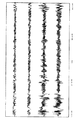
これにより、被測定者への負担を軽減して、一目で被測定者の睡眠のレベルを把握することができる。図20は、本願発明者らが、実際の被測定者に対して測定装置100を用いて測定を行なった結果と、当該被測定者の睡眠ポリグラフ(PSG)検査の睡眠経過図とを並べて表わした図である。図20に示されるように、測定装置100を用いた場合、睡眠ポリグラフ(PSG)検査の検査結果で表わされた睡眠深度と相関性のある睡眠のレベルが得られることがわかる。そのため、測定装置100を用いることで、非侵襲で被測定者への負担を軽減して、概ね睡眠深度と同様にとらえることのできる睡眠のレベルを得ることができる。
Thereby, the burden on the measurement subject can be reduced, and the level of sleep of the measurement subject can be grasped at a glance. FIG. 20 shows the result of the measurement performed by the inventors of the present application on the actual person to be measured using the
さらに、図10や図11に示されたように、複数の測定期間について、時間軸をそろえて測定結果を表示することで、当該複数の測定期間について当該被測定者の睡眠のレベルを比較することができ、当該被測定者の睡眠のパターンを容易に確認することができる。 Furthermore, as shown in FIG. 10 and FIG. 11, for a plurality of measurement periods, the measurement results are displayed with the time axis aligned, thereby comparing the sleep level of the measurement subject for the plurality of measurement periods. And the sleep pattern of the measurement subject can be easily confirmed.
今回開示された実施の形態はすべての点で例示であって制限的なものではないと考えられるべきである。本発明の範囲は上記した説明ではなくて特許請求の範囲によって示され、特許請求の範囲と均等の意味および範囲内でのすべての変更が含まれることが意図される。 The embodiment disclosed this time should be considered as illustrative in all points and not restrictive. The scope of the present invention is defined by the terms of the claims, rather than the description above, and is intended to include any modifications within the scope and meaning equivalent to the terms of the claims.
10 ボタン、20 表示部、30 センサ、31 体動センサ、40 制御部、41 CPU、42 メモリ、50 通信部、100 測定装置、200 表示装置、401 入力部、402 第1判別部、403 決定部、404 生成部、405 格納部、406 読出部、407 表示制御部、408 通信制御部、409 第2判別部、4021 判別部、4022 補正部。 10 button, 20 display unit, 30 sensor, 31 body motion sensor, 40 control unit, 41 CPU, 42 memory, 50 communication unit, 100 measuring device, 200 display device, 401 input unit, 402 first determination unit, 403 determination unit , 404 generation unit, 405 storage unit, 406 reading unit, 407 display control unit, 408 communication control unit, 409 second determination unit, 4021 determination unit, 4022 correction unit.
Claims (8)
前記体動検出手段の検出結果に基づいて、所定期間の前記被験者の睡眠状態のレベルを時間軸に沿ったグラフで表示装置に表示させる表示データを生成する演算手段とを備え、
前記演算手段は、
前記体動検出手段の検出結果に基づいて、単位期間ごとの前記被験者の睡眠状態を判別する第1の判別手段と、
前記第1の判別手段で判別された前記単位期間ごとの睡眠状態に基づいて、前記単位期間が所定数連続してなる前記所定期間の睡眠状態のレベルを判別する第2の判別手段と、
前記所定期間の睡眠状態のレベルに応じて、当該所定期間ごとの表示態様を決定する決定手段と、
前記所定期間の睡眠状態のレベルを前記表示態様で表わした表示データを生成する生成手段とを含む、睡眠評価装置。 And body motion detecting means that detect the movement of the subject's body,
Based on the detection result of the body movement detecting means, and a computation unit that generates display data to be displayed on the display device graphically the level of sleep state along the time axis of the subject for a predetermined period,
The computing means is
Based on the detection result of the body movement detecting means, a first discriminating means you determine the sleep state of the subject per unit period,
Based on the sleep state for each unit period determined by the first determination unit, a second determination unit for determining the level of the sleep state of the predetermined period in which the unit period is continuously a predetermined number;
Depending on the level of the sleeping state of the predetermined period, a decision means that determine the display mode of each said predetermined period,
Wherein and a generate unit that generates a display data representing a level of sleep state for a predetermined period in the display mode, the sleep evaluation device.
前記決定手段は、前記所定期間の睡眠状態のレベルに応じて、当該所定期間を表わすセグメントの表示態様を決定する、請求項1に記載の睡眠評価装置。 The display data is data for continuously displaying segments representing the predetermined period along the time axis,
The sleep evaluation apparatus according to claim 1, wherein the determination unit determines a display mode of a segment representing the predetermined period according to the level of the sleep state of the predetermined period.
前記決定手段は、前記所定期間を表わすセグメントの前記睡眠状態のレベルを表わす軸の方向の表示位置を、前記睡眠状態のレベルに応じた位置に決定する、請求項2または3に記載の睡眠評価装置。 The display data is data for continuously displaying a segment representing the predetermined period according to an axis representing a level of a sleep state intersecting the time axis along the time axis,
The sleep evaluation according to claim 2 or 3, wherein the determining unit determines a display position in an axis direction representing the sleep state level of the segment representing the predetermined period as a position corresponding to the sleep state level. apparatus.
前記単位期間における前記体動の大きさおよび/または前記体動の周期性に基づいて前記単位期間の前記被験者の睡眠状態を判別する判別手段と、
前記単位期間の前記被験者の睡眠状態を、前記単位期間に隣接する単位期間の前記被験者の睡眠状態の判別結果に基づいて補正する補正手段とを含む、請求項1〜5のいずれかに記載の睡眠評価装置。 The first discrimination means includes
And the body movement of the size and / or determine another means you determine the sleep state of the subject of the unit period based on the period of the body motion in the unit period,
Sleep state of the subject of the unit period, based on the discrimination result of the sleeping state of the subject unit period which is adjacent to the unit period and a compensation unit that be corrected, in any one of claims 1 to 5 The sleep evaluation apparatus described.
前記生成手段は、複数日についての前記時間帯の前記被験者の睡眠状態のレベルを、同一時間軸で表示させる表示データを生成する、請求項1〜6のいずれかに記載の睡眠評価装置。 The predetermined period is a period to which a predetermined time zone of a day belongs,
The sleep evaluation apparatus according to any one of claims 1 to 6, wherein the generation unit generates display data for displaying the level of the sleep state of the subject in the time period for a plurality of days on the same time axis.
前記センサ信号の入力を受付けるステップと、
前記センサ信号に基づいて、単位期間ごとの前記被験者の睡眠状態を判別するステップと、
前記単位期間ごとの睡眠状態の判別結果に基づいて、前記単位期間が連続してなる前記所定期間の睡眠状態のレベルを判別するステップと、
前記所定期間の睡眠状態のレベルに応じて、当該所定期間ごとの表示態様を決定するステップと、
前記所定期間の睡眠状態のレベルを前記表示態様で表わした表示データを生成するステップとを備える、睡眠評価装置における表示方法。 This is a display method in the sleep evaluation apparatus, in which the level of the sleep state of the subject for a predetermined period is displayed on the display device in a graph along the time axis based on a sensor signal from the sensor that detects the body movement of the subject. And
Receiving the sensor signal input;
Determining the sleep state of the subject for each unit period based on the sensor signal;
Determining a sleep state level of the predetermined period in which the unit period is continuous based on a determination result of the sleep state for each unit period; and
Determining a display mode for each predetermined period according to the level of sleep state of the predetermined period;
And a step of generating display data representing the level of the sleep state of the predetermined period in the display mode.
Priority Applications (5)
| Application Number | Priority Date | Filing Date | Title |
|---|---|---|---|
| JP2011035705A JP5720295B2 (en) | 2011-02-22 | 2011-02-22 | Sleep evaluation apparatus and display method in sleep evaluation apparatus |
| PCT/JP2011/076264 WO2012114588A1 (en) | 2011-02-22 | 2011-11-15 | Sleep evaluation device and display method for sleep evaluation device |
| CN201180068312.0A CN103391745B (en) | 2011-02-22 | 2011-11-15 | Sleep evaluation device and the display packing of sleep evaluation device |
| US13/982,421 US8933809B2 (en) | 2011-02-22 | 2011-11-15 | Sleep evaluation device and display method for sleep evaluation device |
| DE112011104932.3T DE112011104932T5 (en) | 2011-02-22 | 2011-11-15 | Sleep evaluation device and sleep evaluation device display method |
Applications Claiming Priority (2)
| Application Number | Priority Date | Filing Date | Title |
|---|---|---|---|
| JP2011035705A JP5720295B2 (en) | 2011-02-22 | 2011-02-22 | Sleep evaluation apparatus and display method in sleep evaluation apparatus |
| PCT/JP2011/076264 WO2012114588A1 (en) | 2011-02-22 | 2011-11-15 | Sleep evaluation device and display method for sleep evaluation device |
Publications (3)
| Publication Number | Publication Date |
|---|---|
| JP2012170624A JP2012170624A (en) | 2012-09-10 |
| JP2012170624A5 JP2012170624A5 (en) | 2014-03-20 |
| JP5720295B2 true JP5720295B2 (en) | 2015-05-20 |
Family
ID=46720392
Family Applications (1)
| Application Number | Title | Priority Date | Filing Date |
|---|---|---|---|
| JP2011035705A Active JP5720295B2 (en) | 2011-02-22 | 2011-02-22 | Sleep evaluation apparatus and display method in sleep evaluation apparatus |
Country Status (5)
| Country | Link |
|---|---|
| US (1) | US8933809B2 (en) |
| JP (1) | JP5720295B2 (en) |
| CN (1) | CN103391745B (en) |
| DE (1) | DE112011104932T5 (en) |
| WO (1) | WO2012114588A1 (en) |
Families Citing this family (21)
| Publication number | Priority date | Publication date | Assignee | Title |
|---|---|---|---|---|
| US20140296661A1 (en) * | 2011-10-25 | 2014-10-02 | Koninklijke Philips N.V. | Sleep stage annotation system for infants |
| KR101341291B1 (en) | 2012-09-26 | 2013-12-12 | 세종대학교산학협력단 | Method of quiescence state recognition based on depth sensor and apparatus thereof |
| US9694156B2 (en) | 2014-06-05 | 2017-07-04 | Eight Sleep Inc. | Bed device system and methods |
| US9186479B1 (en) | 2014-06-05 | 2015-11-17 | Morphy Inc. | Methods and systems for gathering human biological signals and controlling a bed device |
| WO2016067449A1 (en) * | 2014-10-31 | 2016-05-06 | 富士通株式会社 | State display method, program, and state display device |
| JP6337972B2 (en) * | 2014-10-31 | 2018-06-06 | 富士通株式会社 | Status display method, program, and status display device |
| US10206618B2 (en) * | 2015-02-17 | 2019-02-19 | Microsoft Technology Licensing, Llc | Optimized visibility for sleep sessions over time |
| WO2017040333A1 (en) * | 2015-08-28 | 2017-03-09 | Awarables, Inc. | Visualizing, scoring, recording, and analyzing sleep data and hypnograms |
| WO2017040331A1 (en) * | 2015-08-28 | 2017-03-09 | Awarables, Inc. | Determining sleep stages and sleep events using sensor data |
| US10105092B2 (en) | 2015-11-16 | 2018-10-23 | Eight Sleep Inc. | Detecting sleeping disorders |
| US10154932B2 (en) | 2015-11-16 | 2018-12-18 | Eight Sleep Inc. | Adjustable bedframe and operating methods for health monitoring |
| JP6439729B2 (en) * | 2016-03-24 | 2018-12-19 | トヨタ自動車株式会社 | Sleep state estimation device |
| US10325514B2 (en) * | 2016-06-02 | 2019-06-18 | Fitbit, Inc. | Systems and techniques for tracking sleep consistency and sleep goals |
| WO2018221364A1 (en) * | 2017-05-30 | 2018-12-06 | パナソニックIpマネジメント株式会社 | Drowsiness estimating device, awakening-induction control device, and awakening induction system |
| GB2584242B (en) | 2018-01-09 | 2022-09-14 | Eight Sleep Inc | Systems and methods for detecting a biological signal of a user of an article of furniture |
| GB2584241B (en) | 2018-01-19 | 2023-03-08 | Eight Sleep Inc | Sleep pod |
| JP7344213B2 (en) | 2018-03-02 | 2023-09-13 | 日東電工株式会社 | Methods, computing devices, and wearable devices for sleep stage detection |
| JP7205145B2 (en) * | 2018-10-02 | 2023-01-17 | カシオ計算機株式会社 | Electronic clock and display method |
| JP7180318B2 (en) * | 2018-11-26 | 2022-11-30 | 株式会社アイシン | Opening/closing body control device |
| JP7425573B2 (en) * | 2019-10-02 | 2024-01-31 | シャープ株式会社 | Electronics |
| KR20240126242A (en) * | 2023-02-13 | 2024-08-20 | 주식회사 브레인유 | Method and computer program for providing sleep analysis information |
Family Cites Families (8)
| Publication number | Priority date | Publication date | Assignee | Title |
|---|---|---|---|---|
| JPS60113111A (en) * | 1983-11-24 | 1985-06-19 | Res Dev Corp Of Japan | Analyzer for action state of small animal |
| JP4390535B2 (en) * | 2003-11-26 | 2009-12-24 | 横河電機株式会社 | Sleep stage estimation method and apparatus using the method |
| JP2005237570A (en) * | 2004-02-25 | 2005-09-08 | Daikin Ind Ltd | Sleep state decision system, sleep state decision method, and sleep state decision program |
| US8532737B2 (en) * | 2005-12-29 | 2013-09-10 | Miguel Angel Cervantes | Real-time video based automated mobile sleep monitoring using state inference |
| JP2007195823A (en) * | 2006-01-27 | 2007-08-09 | Daikin Ind Ltd | Sleep information providing system |
| JP4357503B2 (en) | 2006-06-28 | 2009-11-04 | 株式会社東芝 | Biological information measuring device, biological information measuring method, and biological information measuring program |
| JP4103925B1 (en) | 2006-12-08 | 2008-06-18 | ダイキン工業株式会社 | Sleep determination device |
| JP4680252B2 (en) * | 2007-12-28 | 2011-05-11 | 株式会社タニタ | Sleep evaluation apparatus and sleep evaluation method |
-
2011
- 2011-02-22 JP JP2011035705A patent/JP5720295B2/en active Active
- 2011-11-15 US US13/982,421 patent/US8933809B2/en active Active
- 2011-11-15 WO PCT/JP2011/076264 patent/WO2012114588A1/en active Application Filing
- 2011-11-15 CN CN201180068312.0A patent/CN103391745B/en active Active
- 2011-11-15 DE DE112011104932.3T patent/DE112011104932T5/en active Pending
Also Published As
| Publication number | Publication date |
|---|---|
| WO2012114588A9 (en) | 2013-07-25 |
| DE112011104932T5 (en) | 2014-01-30 |
| US8933809B2 (en) | 2015-01-13 |
| WO2012114588A1 (en) | 2012-08-30 |
| CN103391745B (en) | 2016-08-10 |
| JP2012170624A (en) | 2012-09-10 |
| US20130310712A1 (en) | 2013-11-21 |
| CN103391745A (en) | 2013-11-13 |
Similar Documents
| Publication | Publication Date | Title |
|---|---|---|
| JP5720295B2 (en) | Sleep evaluation apparatus and display method in sleep evaluation apparatus | |
| JP5724479B2 (en) | Sleep evaluation apparatus and sleep evaluation method | |
| JP5788251B2 (en) | Sleep information detection device and detection method in sleep information detection device | |
| JP5788293B2 (en) | Sleep evaluation apparatus and sleep evaluation program | |
| US10939848B2 (en) | Method and apparatus for assessing respiratory distress | |
| JP5949008B2 (en) | Sleep depth determination device and control method | |
| JP2006204742A (en) | Method and system for evaluating sleep, its operation program, pulse oxymeter, and system for supporting sleep | |
| JP5857609B2 (en) | Sleep state discrimination device | |
| JP2010068968A (en) | Body motion distinguishing apparatus, and activity meter | |
| JP5776939B2 (en) | Sleep state determination device and sleep state determination method | |
| JP2007061439A (en) | Living body information measuring device and its method | |
| JP2007181613A (en) | Method and apparatus for analyzing respiratory signal obtained by change of subject's load applied to bedding | |
| US9072491B2 (en) | Sleep evaluation device and sleep evaluation method | |
| JP2011103914A (en) | Muscle tone measuring instrument, muscle tone measuring method, and muscle tone measuring program | |
| JP6241079B2 (en) | Weight measuring device | |
| JP2016087355A (en) | Sleep state determination device, and sleep state determination method and program | |
| EP1902674B1 (en) | Apparatus for measuring calories consumed during sleep | |
| JP6186896B2 (en) | Sleep determination device and sleep determination method | |
| JP2019154857A (en) | Sleep/awakening determination system | |
| JP2007283030A (en) | Apparatus for determining respiratory condition during sleep | |
| KR102538356B1 (en) | Method and device for monitoring sleep state using sleep prediction model | |
| Heise et al. | Unobtrusively detecting apnea and hypopnea events via a hydraulic bed sensor | |
| JP3627741B2 (en) | Sleep breathing information measuring device | |
| JP6013002B2 (en) | Biological signal display device and control method thereof | |
| JP6127738B2 (en) | Sleep determination device |
Legal Events
| Date | Code | Title | Description |
|---|---|---|---|
| A621 | Written request for application examination |
Free format text: JAPANESE INTERMEDIATE CODE: A621 Effective date: 20140107 |
|
| A521 | Request for written amendment filed |
Free format text: JAPANESE INTERMEDIATE CODE: A523 Effective date: 20140131 |
|
| A131 | Notification of reasons for refusal |
Free format text: JAPANESE INTERMEDIATE CODE: A131 Effective date: 20141216 |
|
| A521 | Request for written amendment filed |
Free format text: JAPANESE INTERMEDIATE CODE: A523 Effective date: 20150202 |
|
| TRDD | Decision of grant or rejection written | ||
| A01 | Written decision to grant a patent or to grant a registration (utility model) |
Free format text: JAPANESE INTERMEDIATE CODE: A01 Effective date: 20150224 |
|
| A61 | First payment of annual fees (during grant procedure) |
Free format text: JAPANESE INTERMEDIATE CODE: A61 Effective date: 20150309 |
|
| R150 | Certificate of patent or registration of utility model |
Ref document number: 5720295 Country of ref document: JP Free format text: JAPANESE INTERMEDIATE CODE: R150 |