JP5718349B2 - Disinfection cap, system and related methods - Google Patents

Disinfection cap, system and related methods Download PDF

Info

Publication number
JP5718349B2
JP5718349B2 JP2012537172A JP2012537172A JP5718349B2 JP 5718349 B2 JP5718349 B2 JP 5718349B2 JP 2012537172 A JP2012537172 A JP 2012537172A JP 2012537172 A JP2012537172 A JP 2012537172A JP 5718349 B2 JP5718349 B2 JP 5718349B2
Authority
JP
Japan
Prior art keywords
cap
chamber
pad
disinfectant
male
Prior art date
Legal status (The legal status is an assumption and is not a legal conclusion. Google has not performed a legal analysis and makes no representation as to the accuracy of the status listed.)
Active
Application number
JP2012537172A
Other languages
Japanese (ja)
Other versions
JP2013509274A (en
JP2013509274A5 (en
Inventor
ドナルド ディー. ソロモン,
ドナルド ディー. ソロモン,
マーク エフ. ファーガソン,
マーク エフ. ファーガソン,
ロバート ヒッチコック,
ロバート ヒッチコック,
スティーブン バンディス,
スティーブン バンディス,
ジェイムズ マーサー,
ジェイムズ マーサー,
マイケル ハウレット,
マイケル ハウレット,
Original Assignee
カテーテル コネクションズ, インコーポレイテッド
Priority date (The priority date is an assumption and is not a legal conclusion. Google has not performed a legal analysis and makes no representation as to the accuracy of the date listed.)
Filing date
Publication date
Priority claimed from US12/610,033 external-priority patent/US8647326B2/en
Priority claimed from US12/610,141 external-priority patent/US8172825B2/en
Application filed by カテーテル コネクションズ, インコーポレイテッド, カテーテル コネクションズ, インコーポレイテッド filed Critical カテーテル コネクションズ, インコーポレイテッド
Publication of JP2013509274A publication Critical patent/JP2013509274A/en
Publication of JP2013509274A5 publication Critical patent/JP2013509274A5/ja
Application granted granted Critical
Publication of JP5718349B2 publication Critical patent/JP5718349B2/en
Active legal-status Critical Current
Anticipated expiration legal-status Critical

Links

Images

Classifications

    • AHUMAN NECESSITIES
    • A61MEDICAL OR VETERINARY SCIENCE; HYGIENE
    • A61MDEVICES FOR INTRODUCING MEDIA INTO, OR ONTO, THE BODY; DEVICES FOR TRANSDUCING BODY MEDIA OR FOR TAKING MEDIA FROM THE BODY; DEVICES FOR PRODUCING OR ENDING SLEEP OR STUPOR
    • A61M39/00Tubes, tube connectors, tube couplings, valves, access sites or the like, specially adapted for medical use
    • A61M39/20Closure caps or plugs for connectors or open ends of tubes
    • AHUMAN NECESSITIES
    • A61MEDICAL OR VETERINARY SCIENCE; HYGIENE
    • A61MDEVICES FOR INTRODUCING MEDIA INTO, OR ONTO, THE BODY; DEVICES FOR TRANSDUCING BODY MEDIA OR FOR TAKING MEDIA FROM THE BODY; DEVICES FOR PRODUCING OR ENDING SLEEP OR STUPOR
    • A61M39/00Tubes, tube connectors, tube couplings, valves, access sites or the like, specially adapted for medical use
    • A61M39/10Tube connectors; Tube couplings
    • A61M39/16Tube connectors; Tube couplings having provision for disinfection or sterilisation
    • A61M39/162Tube connectors; Tube couplings having provision for disinfection or sterilisation with antiseptic agent incorporated within the connector

Description

(1.技術分野)
本開示は、概して、医療用コネクタのキャップに関し、より具体的には、流体流動または流体送達システムに利用されてもよいコネクタ等の未接続医療用コネクタの滅菌状態を保護するために使用することができるキャップに関する。一部の実施形態は、細長い雄部分を含む医療用コネクタのキャップを対象とする。
(1. Technical field)
The present disclosure relates generally to medical connector caps, and more particularly to use to protect the sterility of unconnected medical connectors, such as connectors that may be utilized in fluid flow or fluid delivery systems. It is related with the cap which can do. Some embodiments are directed to a cap of a medical connector that includes an elongated male portion.

(2.関連技術)
血管内カテーテルを介して患者に進入する微生物によって引き起こされる場合があるような血流感染症は、疾病および過剰な医療費の重大な原因である。相当数のそのような感染症が、米国の集中治療室で毎年発生している。加えて、これらの感染症のかなりの割合が死亡をもたらす。
(2. Related technology)
Bloodstream infections, which can be caused by microorganisms entering the patient via an intravascular catheter, are a significant cause of illness and excessive medical costs. A significant number of such infections occur each year in the US intensive care unit. In addition, a significant proportion of these infections result in death.

アメリカ疾病管理予防センター(Centers for Disease Control and Prevention)によるガイドラインは、病院、外来患者、および在宅介護設定における血流感染症を制限する種々の方法を説明している。ガイドラインは、手の衛生、カテーテル部位のケア、および混合物調製等の問題に対処する。しかしながら、これらのガイドラインにもかかわらず、そのような感染症は、比較的不変の速度でヘルスケアシステムを悩まし続けている。   Guidelines by the Centers for Disease Control and Prevention describe various ways to limit bloodstream infections in hospitals, outpatients, and home care settings. The guidelines address issues such as hand hygiene, catheter site care, and mixture preparation. However, despite these guidelines, such infections continue to plague healthcare systems at a relatively constant rate.

種々の抗菌剤でカテーテルを含浸することが、これらの感染症を低減するための1つのアプローチである。しかしながら、含浸したカテーテルは、満足のいかない結果を提供する。加えて、いくつかの微生物は、カテーテルで使用される種々の抗菌剤に対する抵抗を生じている。他のシステムおよびアプローチも開発されているが、これらは同様に種々の制限および欠点に悩まされている。   Impregnating catheters with various antibacterial agents is one approach to reducing these infections. However, impregnated catheters provide unsatisfactory results. In addition, some microorganisms have created resistance to various antibacterial agents used in catheters. Other systems and approaches have been developed, but they also suffer from various limitations and drawbacks.

本発明は、例えば、以下を提供する:
(項目1)
医療用コネクタを消毒するように構成されるキャップであって、
該キャップは、
接続界面を画定する筐体であって、該接続界面によって、該キャップは、医療用コネクタに連結されることができ、該筐体は、チャンバをさらに画定する、筐体と、
該チャンバ内の消毒剤と、
該チャンバに対して移動可能である該チャンバ内の密封部材であって、該密封部材は、該キャップが該医療用コネクタに連結されると、該医療用コネクタの雄突起部に接触するように構成される、密封部材と、
該密封部材と連結される付勢部材であって、該付勢部材によって提供されるバイアスは、該チャンバの中への該医療用コネクタの雄突起部の挿入に対抗するように方向付けられ、それにより、該キャップが該医療用コネクタと連結されている際に、該雄突起部と該密封部材との間の流体密密封が生成または維持されることができ、該密封部材は、医療用コネクタの雄突起部が該チャンバの中に挿入される際に、該チャンバ内で移動するように構成されて、消毒剤が該密封部材の一つの側面から該密封部材の別の側面まで移動し、および該雄突起部の少なくとも一部分と接触するようにさせる、付勢部材と
を備える、キャップ。
(項目2)
前記付勢部材は、弾力性パッドを備え、該弾力性パッドは、前記キャップが使用前状態にあるときに、前記消毒剤の少なくとも一部分を中に含む、項目1に記載のキャップ。
(項目3)
前記パッドを通る横断面は、形状が円形または長方形である、項目1または2に記載のキャップ。
(項目4)
前記付勢部材は、弾力性支持材をさらに備え、前記パッドは、該支持材と前記密封部材との間に載置され、該支持材と該密封部材とは、前記キャップが医療用コネクタに連結されて該パッドから消毒剤を押し進める際に、協働して該パッドを圧縮するように構成される、項目1〜3のうちのいずれかに記載のキャップ。
(項目5)
前記支持材は、前記パッドほど柔軟ではないことにより、該パッドが該支持材よりも容易に圧縮される、項目1〜4のうちのいずれかに記載のキャップ。
(項目6)
前記チャンバは、剛性支柱を含み、該剛性支柱は、前記弾力性支持材の移動を拘束するように構成される、項目1〜5のうちのいずれかに記載のキャップ。
(項目7)
前記筐体は、前記チャンバに対して内向きに突出する棚を画定し、前記密封部材は、前記キャップが使用前構成にあるときに、該棚を介して該チャンバ内に保持される、項目1〜6のうちのいずれかに記載のキャップ。
(項目8)
前記密封部材は、前記キャップが前記使用前構成にあるときに、前記棚との流体密密封を形成する、項目1〜7のうちのいずれかに記載のキャップ。
(項目9)
医療用コネクタの雄突起部は、管腔を画定し、前記密封部材は、流体が該管腔に進入することを防止できる該雄突起部との流体密密封を生成するように構成される、項目1〜8のうちのいずれかに記載のキャップ。
(項目10)
前記付勢部材は、前記キャップが前記医療用コネクタから分断される際に、前記密封部材と前記雄突起部との間の前記流体密密封を維持するように構成される、項目1〜9のうちのいずれかに記載のキャップ。
(項目11)
前記密封部材の表面は、実質的に円錐形であり、該円錐表面の頂点は、前記雄突起部の前記管腔の中に受容されるように構成される、項目1〜10のうちのいずれかに記載のキャップ。
(項目12)
前記筐体は、前記チャンバの少なくとも一部分を画定する側壁を備え、該側壁の少なくとも一部分は、テーパ状であることにより、雄ルアーとの密封を形成する、項目1〜11のうちのいずれかに記載のキャップ。
(項目13)
前記密封部材は、前記側壁の近位端に対して十分に大きい距離だけ陥凹しており、それにより、前記雄ルアーが該密封部材に接触する前に、該雄ルアーの少なくとも一部分が該側壁内に受容されることを可能にする、項目1〜12のうちのいずれかに記載のキャップ。
(項目14)
前記距離が十分に小さく、それにより、前記雄ルアーが前記側壁との密封を形成する前に、該雄ルアーが該側壁内に受容されることを可能にして、前記密封部材との密封を形成する、項目1〜13のうちのいずれかに記載のキャップ。
(項目15)
前記密封部材は、十分に小さい距離だけ前記側壁の近位端に対して陥凹しており、それにより、雄ルアーが該側壁との密封を形成する前に、該雄ルアーの少なくとも一部分が該側壁内に受容され、該密封部材との密封を形成することを可能にする、項目1〜14のうちのいずれかに記載のキャップ。
(項目16)
前記筐体は、近位に延在する突起を画定し、該突起は、それの外向きに方向付けられた表面に前記接続界面を含み、該筐体は、付加的な接続界面をさらに画定し、該接続界面は、スリーブと連結されて、それとの流体密密封を形成するように構成される、項目1〜15のうちのいずれかに記載のキャップ。
(項目17)
前記近位に延在する突起は、前記キャップが前記スリーブと連結されるとき、該スリーブによって画定される管腔内にある、項目1〜16のうちのいずれかに記載のキャップ。
(項目18)
前記筐体は、1つ以上の排出口を画定し、該1つ以上の排出口は、該筐体と医療用コネクタの雄突起部との間の流体密密封の形成を防止するように構成される、項目1〜17のうちのいずれかに記載のキャップ。
(項目19)
ポートをさらに備え、消毒剤は、該ポートを通過して前記密封部材の一つの側面からそれの別の側面まで移動する、項目1〜18のうちのいずれかに記載のキャップ。
(項目20)
前記ポートは、前記密封部材の中に配置されるチャネルおよび二方弁のうちの1つ以上を備える、項目1〜19のうちのいずれかに記載のキャップ。
(項目21)
前記ポートは、前記密封部材の周囲と前記側壁との間に間隙を備える、項目1〜20のうちのいずれかに記載のキャップ。
(項目22)
障壁を有する排出口をさらに備え、該障壁は、微生物が該排出口を介して該チャンバに進入することを阻止するように構成される、項目1〜21のうちのいずれかに記載のキャップ。
(項目23)
1つ以上の医療用コネクタを消毒するように構成されるアセンブリであって、
該アセンブリは、
消毒剤を含むパッドが中に載置されるチャンバを画定する雌キャップと、
消毒剤が中に載置されるチャンバを画定する雄キャップであって、該雄キャップは、該チャンバ内で移動可能である密封部材をさらに備え、該密封部材は、該雄キャップが医療用コネクタに連結されるときに、該医療用コネクタの雄突起部との密封を形成するように構成され、およびある量の消毒剤が、該密封部材の一つの側面からそれの別の側面まで移動することを可能にするように変位させられるように構成される、雄キャップと、
第1の端部および第2の端部を画定するスリーブであって、該アセンブリが使用前状態にあるとき、該スリーブの該第1の端部は、該雌キャップに連結されて、それと流体密密封を形成し、該スリーブの該第2の端部は、該雄キャップに連結されて、それと流体密密封を形成し、それにより、該アセンブリは、該使用前状態にあるときに、自身からの消毒剤の蒸発損失を防止するスリーブと
を備える、アセンブリ。
(項目24)
前記雌キャップの前記パッドを通る横断面は、形状が円形または長方形である、項目23に記載のアセンブリ。
(項目25)
前記雄キャップは、前記消毒剤を含む弾力性パッドを備え、該弾力性パッドは、該雄キャップの開放端に向かって方向付けられる前記密封部材に付勢力を提供するように構成される、項目23または24に記載のアセンブリ。
(項目26)
前記雄キャップの前記弾力性パッドを通る横断面は、形状が円形または長方形である、項目23〜25のうちのいずれかに記載のアセンブリ。
(項目27)
弾力性支持材をさらに備え、前記弾力性パッドは、該弾力性支持材と前記密封部材との間に載置される、項目23〜26のうちのいずれかに記載のアセンブリ。
(項目28)
前記弾力性支持材は、前記弾力性パッドほど圧縮性ではない、項目23〜27のうちのいずれかに記載のアセンブリ。
(項目29)
前記雄および雌キャップの各々に対する1つ以上の分離支援をさらに備える、項目23〜28のうちのいずれかに記載のアセンブリ。
(項目30)
分離支援は、前記雄および雌キャップのうちの1つのフランジに陥凹を備え、該陥凹は、該スリーブの突起部と協働する、項目23〜29のうちのいずれかに記載のアセンブリ。
(項目31)
前記フランジは、実質的に平面的な面を備え、該面は、前記雄および雌キャップのうちの前記1つの長手軸を通って垂直に延在する横断面の平面に対して角度を成し、該面は、約20度以上である該面に対する角度を画定する、項目23〜30のうちのいずれかに記載のアセンブリ。
(項目32)
分離支援は、前記スリーブに対する前記雄および雌キャップのうちの1つの回転時に、該スリーブから長手方向に離れるように該雄および雌キャップのうちの該1つにカム作用するように構成される、項目23〜31のうちのいずれかに記載のアセンブリ。
(項目33)
前記分離支援は、前記スリーブに対する前記回転が時計回り方向であろうと反時計回り方向であろうと、前記雄および雌キャップのうちの前記1つにカム作用するように構成される、項目23〜32のうちのいずれかに記載のアセンブリ。
(項目34)
前記スリーブの前記第1の端部と第2の端部とは、相互に同一であり、それにより、該スリーブの該第1の端部が前記雄キャップと連結されることができ、該スリーブの該第2の端部が前記雌キャップと連結されることができる、項目23〜33のうちのいずれかに記載のアセンブリ。
(項目35)
前記雄および雌キャップの各々は、ハンドルを備え、該ハンドルは、該雄および雌キャップの把持および回転を容易にするように構成される、項目23〜34のうちのいずれかに記載のアセンブリ。
(項目36)
前記スリーブは、長手軸を画定し、前記雄キャップは、前記アセンブリが前記使用前状態にあるとき、該スリーブの該長手軸と垂直である面を通って延在する雄突起部分を備える、項目23〜35のうちのいずれかに記載のアセンブリ。
(項目37)
前記スリーブは、補強リブを備える、項目23〜36のうちのいずれかに記載のアセンブリ。
(項目38)
医療用コネクタを消毒する方法であって、
該方法は、
雄キャップを提供することであって、該雄キャップは、
接続界面、ならびに近位端および遠位端を有するチャンバを画定する筐体と、
該チャンバ内の消毒剤と、
該チャンバ内の密封部材と、
該密封部材と連結される付勢部材と
を備える、ことと、
該密封部材との密封を形成するために、医療用コネクタの雄突起部を該チャンバの中に挿入することと、
該雄突起部の少なくとも一部分と接触するように、該密封部材の遠位側から該密封部材の近位側まで消毒剤を移送することと
を含む、方法。
(項目39)
前記接続界面を前記医療用コネクタの補完的な接続界面に取り付けることをさらに含む、項目38に記載の方法。
(項目40)
前記付勢部材は、近位方向に前記密封部材を押し進めるように構成され、該付勢部材によって提供される付勢力は、前記雄突起部と該密封部材との間の前記密封を強化するために該雄突起部が前記チャンバにさらに挿入されるにつれて増加する、項目38または39に記載の方法。
(項目41)
弾力性パッドは、前記雄キャップが使用前状態であるときに、前記消毒剤を含み、前記方法は、該パッドから消毒剤を押し進めることをさらに含む、項目38〜40のうちのいずれかに記載の方法。
(項目42)
前記雄キャップは、前記パッドの遠位端にある弾力性支持材をさらに備え、前記方法は、該支持材と前記密封部材との間の該パッドを圧縮することをさらに含む、項目38〜41のうちのいずれかに記載の方法。
(項目43)
前記雄キャップの前記筐体と前記医療用コネクタの前記雄突起部との間の密封を形成することをさらに含む、項目38〜42のうちのいずれかに記載の方法。
(項目44)
前記筐体と前記雄突起部との間の前記密封は、前記密封部材が前記チャンバ内を遠位に前進させられた後に形成される、項目38〜43のうちのいずれかに記載の方法。
(項目45)
前記雄キャップは、使用前状態にあるとき、突起部を有するスリーブを備えるアセンブリと連結され、該雄キャップは、該突起部に対して補完的である陥凹を画定し、前記方法は、該スリーブから長手方向に離れるように該雄キャップにカム作用するように、該スリーブに対して該雄キャップを回転させることをさらに含む、項目38〜44のうちのいずれかに記載の方法。
(項目46)
前記雄キャップは、使用前状態にあるとき、消毒剤を中に含む雌キャップを備えるアセンブリと連結される、項目38〜45のうちのいずれかに記載の方法であって、該方法は、
該アセンブリから該雄キャップおよび該雌キャップを分離することと、
該雄キャップを医療用コネクタと接続すること、および該雌キャップを別個の医療用コネクタと接続することのうちの1つ以上のことと
をさらに含む、方法。
(項目47)
医療用コネクタを消毒するように構成されるキャップであって、
該キャップは、
接続界面を画定する筐体であって、該キャップは、該接続界面によって医療用コネクタに連結されることができ、該筐体は、チャンバをさらに画定する、筐体と、
該チャンバ内の消毒剤と、
密封領域を有する密封部材であって、該キャップが該接続界面を介して該医療用コネクタに連結されると、該密封領域において流体密密封が該密封部材と該医療用コネクタの雄ルアーとの間に存在し、該密封部材および該筐体の一方または両方は、1つ以上のポートを備え、該チャンバの遠位端に向かう該密封部材の移動は、該雄ルアーを消毒するために、該チャンバから該1つ以上のポートを通して該消毒剤の少なくとも一部分を放出する、密封部材と
を備える、キャップ。
(項目48)
前記筐体は、前記チャンバの少なくとも一部分を画定する側壁を備え、該側壁は、テーパ状であることにより、雄ルアーとの密封を形成する、項目47に記載のキャップ。
(項目49)
前記密封部材は、十分に大きい距離だけ前記側壁の近位端に対して陥凹しており、それにより、前記雄ルアーが該密封部材に接触する前に、該雄ルアーの少なくとも一部分が該側壁内に受容されることを可能にする、項目47または48に記載のキャップ。
(項目50)
前記距離は、十分に小さく、それにより、前記雄ルアーが前記側壁との密封を形成する前に、該雄ルアーが該側壁内に受容されることを可能にし、前記密封部材との密封を形成する、項目47〜49のうちのいずれかに記載のキャップ。
(項目51)
前記密封部材は、十分に小さい距離だけ前記側壁の端部に対して陥凹しており、それにより、雄ルアーが該側壁との密封を形成する前に、該雄ルアーの少なくとも一部分が該側壁内に受容されることを可能にし、該密封部材との密封を形成する、項目47〜50のうちのいずれかに記載のキャップ。
(項目52)
前記筐体は、1つ以上の排出口を画定し、該1つ以上の排出口は、該筐体と前記雄ルアーとの間の流体密密封の形成を防止するように構成される、項目47〜51のうちのいずれかに記載のキャップ。
(項目53)
前記密封部材は、1つ以上のポートを備え、該1つ以上のポートは、前記密封領域の外側に載置され、それにより、該密封部材が医療用コネクタとの密封を形成すると、該医療用コネクタの管腔に進入することなく、消毒剤が該ポートを通過し、該医療用コネクタの外面に接触することができる、項目47〜52のうちのいずれかに記載のキャップ。
(項目54)
前記筐体は、1つ以上のポートを画定する、項目47〜53のうちのいずれかに記載のキャップ。
(項目55)
障壁を有する排出口をさらに備え、該障壁は、微生物が該排出口を介して前記チャンバに進入することを阻止するように構成される、項目47〜54のうちのいずれかに記載のキャップ。
(項目56)
前記密封部材と連結される付勢部材をさらに備え、該付勢部材は、弾力的に変形可能であることにより、該密封部材が初期配向から変位させられると、該初期配向に向かって該密封部材を付勢する、項目47〜55のうちのいずれかに記載のキャップ。
(項目57)
前記付勢部材は、バネを備える、項目47〜56のうちのいずれかに記載のキャップ。
(項目58)
前記付勢部材は、弾力的な圧縮性パッドを備える、項目47〜57のうちのいずれかに記載のキャップ。
(項目59)
前記パッドは、前記チャンバ内にあり、前記消毒剤の少なくとも一部分を含む、項目47〜58のうちのいずれかに記載のキャップ。
(項目60)
圧縮性パッドをさらに備え、該圧縮性パッドは、前記消毒剤の少なくとも一部分を中に有する、項目47〜59のうちのいずれかに記載のキャップ。
(項目61)
前記密封部材と連結される付勢部材をさらに備え、該付勢部材は、弾力的に変形可能であることにより、該密封部材が初期配向から変位させられると、該初期配向に向かって該密封部材を付勢する、項目47〜60のうちのいずれかに記載のキャップ。
(項目62)
前記付勢部材は、弾力性発泡体およびバネのうちの1つ以上を備える、項目47〜61のうちのいずれかに記載のキャップ。
(項目63)
障壁をさらに備え、該障壁は、前記圧縮性パッドと付勢部材との間に配置される、項目47〜62のうちのいずれかに記載のキャップ。
(項目64)
前記接続界面は、前記筐体の外面にある、項目47〜63のうちのいずれかに記載のキャップ。
(項目65)
消毒剤を中に有する付加的なチャンバを備える付加的なキャップが、前記キャップと連結され、両方のチャンバは、密封されることにより、そこからの消毒剤の蒸発損失を防止する、項目47〜64のうちのいずれかに記載のキャップ。
(項目66)
前記キャップと前記付加的なキャップとは、使用前状態にあるときに、密封スリーブを介して相互に連結される、項目47〜65のうちのいずれかに記載のキャップ。
(項目67)
前記キャップおよび前記付加的なキャップの各々の上に配置されるフランジは、補完的な陥凹と突起部とを含み、該補完的な陥凹と突起部とは、該キャップが反対方向に回転させられる際に分離支援として協働する、項目47〜66のうちのいずれかに記載のキャップ。
(項目68)
前記キャップ、付加的なキャップ、およびスリーブの各々の上に配置されるフランジは、補完的な陥凹と突起部とを含み、該補完的な陥凹と突起部とは、該キャップが反対方向に回転させられる際に、分離支援として協働する、項目47〜67のうちのいずれかに記載のキャップ。
(項目69)
前記1つ以上のポートの各々は、チャネルおよび二方弁のうちの1つ以上を備える、項目47〜68のうちのいずれかに記載のキャップ。
(項目70)
前記筐体の開放表面は、取外し可能なカバーに連結される、項目47〜69のうちのいずれかに記載のキャップ。
(項目71)
医療用コネクタを消毒するように構成されるキャップであって、
該キャップは、
接続界面を画定する筐体であって、該接続界面によって該キャップが医療用コネクタに連結されることができ、該筐体は、チャンバをさらに画定する、筐体と、
該チャンバ内の消毒剤と、
密封領域を有する密封部材であって、雄ルアーの先端がそれと接触しているときに、該密封領域において流体密密封を形成することができる、密封部材と、
該密封部材と連結される付勢部材と
を備え、
該付勢部材によって提供されるバイアスは、該チャンバの中への該雄ルアーの挿入に対抗し、それにより、該キャップが医療用コネクタと連結されている際に、該雄ルアーの先端と該密封部材との間の流体密密封が生成または維持され、該チャンバの中への雄ルアーの挿入は、該密封部材の一つの側面から該密封部材の別の側面まで消毒剤を移動させ、それにより、該雄ルアーの一部分を消毒する、キャップ。
(項目72)
前記付勢部材は、弾力性パッドを備える、項目71に記載のキャップ。
(項目73)
前記筐体は、前記チャンバの少なくとも一部分を画定する側壁を備え、前記密封部材は、該側壁との流体密密封を形成する、項目71または72に記載のキャップ。
(項目74)
雄ルアーを備える医療用コネクタを消毒する方法であって、
該方法は、
密封部材およびチャンバを備えるキャップを提供することであって、該チャンバは、消毒剤を含む、ことと、
該キャップを該医療用コネクタに接続することと、
該密封部材と該雄ルアーとの間に流体密密封を生成することと、
該流体密密封を介して該消毒剤が該雄ルアーの内部に進入することを防止しながら、該消毒剤の少なくとも一部分を該医療用コネクタの該雄ルアーの外面と接触するように押し進めることと
を含む、方法。
(項目75)
前記密封部材が初期位置から変位させられると、該初期位置に向かって該密封部材を付勢することと、前記流体密密封を強化することとをさらに含む、項目74に記載の方法。
(項目76)
前記消毒剤の少なくとも一部分を雄ルアーの外面と接触するように押し進める前記ことは、該消毒剤の該少なくとも一部分を前記密封部材によって画定されるポートを通して送ることを含む、項目74または75に記載の方法。
(項目77)
一対の分離された医療用コネクタとともに使用するために構成されるシステムであって、該システムは、
雄キャップであって、該雄キャップは、該雄キャップを第1の医療用コネクタと連結する第1の手段を備え、および該第1の医療用コネクタの雄ルアーを消毒する第1の手段を備える、雄キャップと、
雌キャップであって、該雌キャップは、第2のキャップを第2の医療用コネクタと連結する第2の手段を備え、および該第2の医療用コネクタの少なくとも一部分を消毒する第2の手段を備える、雌キャップと
を備え、
該第1のキャップおよび該第2のキャップは、使用前構成にあるときに相互に取り付けられており、該第1および第2のキャップの各々は、該使用前構成にあるときに密封されており、該雌キャップのいずれの部分も、該雄および雌キャップが該使用前構成にあるときに該消毒する第1の手段を圧縮しない、システム。
(項目78)
前記使用前構成にある前記第1のキャップと第2のキャップとを連結する手段をさらに備える、項目77に記載のシステム。
(項目79)
医療用コネクタとの開封キャップの接続を可能にするために前記雄および雌キャップのいずれか一方を開封することは、該雄および雌キャップの他方を開封することなく達成されることができる、項目77または78に記載のシステム。
(項目80)
雄ルアーの管腔を密封する手段をさらに備える、項目77〜79のうちのいずれかに記載のシステム。
(項目81)
雄ルアーの管腔を密封する前記手段を付勢する手段をさらに備える、項目77〜80のうちのいずれかに記載のシステム。
(項目82)
一対の分離された医療用コネクタとともに使用するために構成されるシステムであって、該システムは、
第1の筐体を備える雄キャップであって、該第1の筐体は、第1のパッドの少なくとも一部分を中に有する第1のチャンバを画定し、該第1のパッドは、消毒剤を含み、該第1の筐体は、該雄キャップを第1の医療用コネクタと連結するように構成される第1の接続界面をさらに画定し、該第1の接続界面は、該第1のチャンバの外側にあり、該第1の医療用コネクタの少なくとも一部分は、該第1の医療用コネクタが該第1の接続界面を介して該雄キャップと連結されると、該第1のパッドを圧縮するように該第1のチャンバの中に受容され、該消毒剤の少なくとも一部分によって消毒されることができる、雄キャップと、
第2の筐体を備える雌キャップであって、該第2の筐体は、第2の接続界面を画定し、、該第2の接続界面は、該雌キャップを第2の医療用コネクタと連結するように構成される、雌キャップと
を備え、
該雄キャップおよび雌キャップは、使用前構成にあるときに、相互に取り付けられ、密封状態にあり、該雄および雌キャップが該使用前構成にあるときに、該雌キャップのいずれの部分も、該第1のチャンバ内にある該第1のパッドの一部分を圧縮しない、システム。
(項目83)
前記第1のパッドの圧縮は、前記消毒剤の少なくとも一部分を該パッドから放出させる、項目82に記載のシステム。
(項目84)
前記第1のチャンバは、雄ルアーを受容するようにサイズ決定される、項目82または83に記載のシステム。
(項目85)
前記第2の筐体は、第2のチャンバを画定し、該第2のチャンバは、消毒剤を中に有する第2のパッドを含み、前記雄および雌キャップが前記使用前構成で相互に取り付けられると、該第2のパッドは、該雄キャップによって圧縮されない、項目82〜84のうちのいずれかに記載のシステム。
(項目86)
前記第2の筐体は、消毒剤を中に有する第2のチャンバを画定し、前記雄キャップの前記第1のチャンバは、該雄キャップおよび前記雌キャップが前記使用前構成にあるとき、該雌キャップの前記第2のチャンバから流体的に隔離される、項目82〜85のうちのいずれかに記載のシステム。
(項目87)
前記第2の筐体は、消毒剤を中に含む第2のチャンバを画定し、前記第2の医療用コネクタの少なくとも一部分は、該第2の医療用コネクタが前記第2の接続界面を介して前記雌キャップと連結されると、該第2のチャンバ内に受容されて、該消毒剤によって消毒される、項目82〜86のうちのいずれかに記載のシステム。
(項目88)
前記第2の筐体は、消毒剤を中に含む第2のチャンバを画定し、前記雄キャップの前記第1のチャンバは、該雄キャップおよび前記雌キャップが前記使用前構成にあると、該雌キャップの該第2のチャンバから流体的に隔離される、項目82〜87のうちのいずれかに記載のシステム。
(項目89)
前記第2の筐体は、消毒剤を中に含む第2のチャンバを画定し、前記第2の接続界面は、該第2のチャンバ内にある、項目82〜88のうちのいずれかに記載のシステム。
(項目90)
前記第2の筐体は、第2のチャンバを画定し、前記雄および雌キャップは、前記使用前構成にあるとき、前記第1のチャンバおよび該第2のチャンバのうちの1つを密封するように相互に協働する、項目82〜89のうちのいずれかに記載のシステム。
(項目91)
医療用コネクタとの開封キャップの接続を可能にするために、前記雄および雌キャップのいずれか一方を開封することは、該雄および雌キャップの他方を開封することなく達成されることができる、項目82−90のうちのいずれかに記載のシステム。
(項目92)
前記雄および雌キャップの一方または両方は、該雄キャップと雌キャップとを相互から着脱することなく開封されることができる、項目82〜91のうちのいずれかに記載のシステム。
(項目93)
前記雄および雌キャップは、それらの使用前構成から容易に着脱可能である、項目82〜92のうちのいずれかに記載のシステム。
(項目94)
前記雄キャップは、第3の接続界面を備え、前記雌キャップは、第4の接続界面を備え、該雄キャップと雌キャップとは、前記使用前構成にあるとき、該第3および第4の接続界面を介して相互に連結される、項目82〜93のうちのいずれかに記載のシステム。
(項目95)
前記雄キャップと雌キャップとは、それらの使用前構成から着脱された後に、前記第3および第4の接続界面を介して相互に選択可能に再び取り付けられることができる、項目82〜94のうちのいずれかに記載のシステム。
(項目96)
前記雄キャップは、前記雄および雌キャップが前記使用前構成で相互に取り付けられるときに、前記第2の接続界面と連結する第3の接続界面を備える、項目82〜95のうちのいずれかに記載のシステム。
(項目97)
前記雄キャップと雌キャップとは、スナップ嵌合、摩擦嵌合、圧入、壊れやすい溶接、共通カバー、および補完ねじ切りのうちの1つ以上を介して、前記使用前構成で相互に接続される、項目82〜96のうちのいずれかに記載のシステム。
(項目98)
前記雄キャップと雌キャップとは、相互に一体的に成形される、項目82〜97のうちのいずれかに記載のシステム。
(項目99)
前記第2の接続界面は、複数の無針注射部位のうちのいずれかと連結するように構成される、項目82〜98のうちのいずれかに記載のシステム。
(項目100)
前記第1および第2の筐体のうちの1つは、接続チャンバを画定し、前記雄キャップと雌キャップとが前記使用前構成で相互に取り付けられると、該第1および第2の筐体のうちの他方の少なくとも一部分が該接続チャンバの中に受容される、項目82〜99のうちのいずれかに記載のシステム。
(項目101)
前記雄キャップと雌キャップとは、前記使用前構成にあるとき、同軸上にある、項目82〜100のうちのいずれかに記載のシステム。
(項目102)
前記第2の筐体は、消毒剤を中に含む第2のチャンバを画定し、前記第1および第2のチャンバの各々は、前記雄および雌キャップが前記使用前構成にあるとき、密封され、同じ方向を向く開放端を画定する、項目82〜101のうちのいずれかに記載のシステム。
(項目103)
前記第2の筐体は、消毒剤を中に含む第2のチャンバを画定し、前記第1および第2のチャンバの各々は、前記雄および雌キャップが前記使用前構成にあるとき、密封され、相互に反対の方向を向く開放端を画定する、項目82〜102のうちのいずれかに記載のシステム。
(項目104)
前記雄キャップは、第1の長手軸を画定し、前記雌キャップは、第2の長手軸を画定し、該第1の長手軸は、該第2の長手軸と同一線上にない、項目82〜103のうちのいずれかに記載のシステム。
(項目105)
一対の分離された医療用コネクタとともに使用するために構成されるシステムであって、該システムは、
第1の筐体を備える雄キャップであって、該第1の筐体は、該雄キャップを第1の医療用コネクタと連結するように構成される第1の接続界面を画定し、該第1の筐体は、第1のチャンバをさらに画定し、消毒液を含む第1のパッドは、該第1のチャンバ内にあり、該第1のチャンバは、該第1の医療用コネクタが該第1の接続界面を介して該雄キャップと連結されると、該第1の医療用コネクタの少なくとも一部分を受容する、雄キャップと、
第2の筐体を備える雌キャップであって、該第2の筐体は、該雌キャップを第2の医療用コネクタと連結するように構成される第2の接続界面を画定し、該第2の筐体は、第2のチャンバをさらに画定し、消毒剤を含む第2のパッドは、該第2のチャンバ内にあり、該第2のチャンバは、該第2の医療用コネクタが該第2の接続界面を介して該雌キャップと連結されると、該第2の医療用コネクタの少なくとも一部分を受容する、雌キャップと、
を備え、
該雄キャップおよび雌キャップは、使用前構成で相互に取り付けられ、該雄および雌キャップの各々は、該使用前構成にあるときに密封されることにより、該雄キャップの該第1のチャンバが該雌キャップの該第2のチャンバから流体的に隔離される、システム。
(項目106)
雄ルアーを備える医療用コネクタを消毒するように構成されるキャップであって、
該キャップは、
接続界面を外面に画定する筐体であって、該キャップは、該接続界面によって、確実であるが取外し可能な取付け状態で医療用コネクタに連結されることができ、該筐体は、少なくとも部分的にチャンバを画定する側壁を含み、該側壁は、雄ルアーが該チャンバの中に挿入されることができる開放端を画定する、筐体と、
パッドであって、該接続界面が該医療用コネクタと連結されると該医療用コネクタの雄ルアーによって圧縮されるように該チャンバの中に載置されるパッドと、
該パッド内の消毒剤と
を備え、
該パッドは、圧縮されると消毒剤を放出するように構成され、該パッドおよび該放出された消毒剤によって提供される摩擦は、該パッドを圧縮する雄ルアーを消毒する、キャップ。
(項目107)
前記側壁の前記開放端は、リップを含み、該リップは、前記雄ルアーとの流体密密封を生成して、消毒剤が前記チャンバから退出することを防止するように構成される、項目106に記載のキャップ。
(項目108)
前記側壁の前記開放端は、1つ以上の排出口を含み、該1つ以上の排出口は、前記筐体と前記雄ルアーとの間の流体密密封の形成を防止するように構成される、項目106または107に記載のキャップ。
(項目109)
雄ルアーを備える医療用コネクタを消毒する方法であって、
該方法は、
消毒剤を中に有するパッドを含むチャンバを備えるキャップを提供することと、
確実であるが解放可能な方式で、雄ルアーを、該キャップを備える医療用コネクタに接続することと、
該雄ルアーを介して該パッドを圧縮して、該パッドから該消毒剤の少なくとも一部分を押し進めることであって、それにより、該雄ルアーを消毒する、ことと
を含む、方法。
(項目110)
前記消毒剤が前記チャンバから退出することを防止するために、前記雄ルアーを介して該チャンバを密封することをさらに含む、項目109に記載の方法。
(項目111)
前記消毒剤が前記チャンバから退出することを可能にするために、1つ以上の排出口を介して該チャンバをベントすることをさらに含む、項目109または110に記載の方法。
(項目112)
前記雄ルアーは、流体通路を画定し、前記方法は、該流体通路に消毒剤を導入することをさらに含む、項目109〜111のうちのいずれかに記載の方法。
(項目113)
医療用コネクタを消毒する方法であって、
該方法は、
雄キャップおよび雌キャップを備えるシステムを提供することであって、該雄キャップと雌キャップとは、使用前状態において相互に接続されており、該雄キャップおよび雌キャップの各々は、密封され、該システムは、消毒剤を含む少なくとも1つのパットを備える、ことと、
第1の医療用コネクタと第2の医療用コネクタとを相互から断絶することと、
該少なくとも1つのパットを減圧することなく、該雄および雌キャップのうちの1つを開封することと、
該少なくとも1つのパッドを圧縮し、そこから消毒剤を放出するために、該雄および雌キャップのうちの1つを、該第1および第2の医療用コネクタのうちの1つと連結することと
を含む、方法。
(項目114)
前記少なくとも1つのパットを減圧することなく、前記雄および雌キャップのうちの他方を開封することと、
該少なくとも1つのパッドを圧縮し、そこから消毒剤を放出するために、該雄および雌キャップのうちの他方を、前記第1および第2の医療用コネクタのうちの他方と連結することと
をさらに含む、項目113に記載の方法。
(項目115)
前記システムは、消毒剤を含む第2のパッドを備え、
該方法は、
該第2のパットを減圧することなく、前記雄および雌キャップのうちの他方を開封することと、
該第2のパッドを圧縮し、そこから消毒剤を放出するために、該雄および雌キャップのうちの他方を、前記第1および第2の医療用コネクタのうちの他方と連結することと
をさらに含む、項目113または114に記載の方法。
(項目116)
医療用コネクタを消毒する方法であって、
該方法は、
雄キャップおよび雌キャップを備えるシステムを提供することであって、該雄キャップと雌キャップとは、使用前状態において相互に接続されており、該雄および雌キャップの各々は、密封され、該システムは、消毒剤を含む少なくとも1つのパットを備える、ことと、
第1の医療用コネクタと第2の医療用コネクタとを相互から断絶することと、
該雄および雌キャップのうちの他方を開封することなく、該雄および雌キャップのうちの1つを開封することと、
該雄および雌キャップのうちの該1つを、該第1および第2の医療用コネクタのうちの1つと連結することと
を含む、方法。
例えば、雄ルアー等の細長い雄部分または雄突起部を有する、例えば、無針注射部位および/または流体移送デバイス等の流体流動または流体送達システムを介して、患者の血流に進入する微生物の脅威を低減することができる、消毒キャップ、ならびに関連システムおよび方法を本明細書において開示する。一部の実施形態において、キャップは、雄突起部を有する医療用コネクタと連結し、それを消毒するように構成される。さらなる実施形態において、キャップは、消毒剤を含むことができ、消毒剤が雄突起部の管腔に進入することを防止するために、雄突起部との密封を生成するように構成することができる。一部の実施形態において、消毒剤は、医療用コネクタへのキャップの連結の前に、パッド内に含有されてもよく、キャップを医療用コネクタに連結する行為は、パッドから消毒剤の少なくとも一部分を押し進め、雄突起部と接触させることができる。種々の実施形態の他の特徴またはさらなる特徴も以下で開示され、この概要の項で参照することにより本明細書に組み込まれる、添付の請求項で記載されている。
The present invention provides, for example:
(Item 1)
A cap configured to disinfect a medical connector,
The cap
A housing defining a connection interface, by which the cap can be coupled to a medical connector, the housing further defining a chamber; and
A disinfectant in the chamber;
A sealing member within the chamber that is movable relative to the chamber such that the sealing member contacts a male protrusion of the medical connector when the cap is coupled to the medical connector. A sealing member comprising:
A biasing member coupled to the sealing member, wherein the bias provided by the biasing member is oriented to oppose insertion of the male protrusion of the medical connector into the chamber; Thereby, when the cap is connected to the medical connector, a fluid tight seal between the male projection and the sealing member can be created or maintained, the sealing member being When the male protrusion of the connector is inserted into the chamber, it is configured to move within the chamber so that the disinfectant moves from one side of the sealing member to another side of the sealing member. And a biasing member that is brought into contact with at least a portion of the male protrusion.
With a cap.
(Item 2)
The cap of claim 1, wherein the biasing member comprises a resilient pad that includes at least a portion of the disinfectant when the cap is in a pre-use state.
(Item 3)
Item 3. The cap according to item 1 or 2, wherein the cross section through the pad is circular or rectangular in shape.
(Item 4)
The biasing member further includes an elastic support member, and the pad is placed between the support member and the sealing member, and the support member and the sealing member include a cap attached to the medical connector. 4. A cap according to any of items 1-3, wherein the cap is configured to cooperate to compress the pad as it pushes the disinfectant from the pad.
(Item 5)
Item 5. The cap of any of items 1-4, wherein the support material is less flexible than the pad, such that the pad is more easily compressed than the support material.
(Item 6)
6. The cap of any of items 1-5, wherein the chamber includes a rigid support, the rigid support being configured to constrain movement of the resilient support.
(Item 7)
The housing defines a shelf that protrudes inwardly relative to the chamber, and the sealing member is retained within the chamber through the shelf when the cap is in a pre-use configuration. The cap in any one of 1-6.
(Item 8)
8. The cap according to any of items 1-7, wherein the sealing member forms a fluid tight seal with the shelf when the cap is in the pre-use configuration.
(Item 9)
The male protrusion of the medical connector defines a lumen, and the sealing member is configured to create a fluid tight seal with the male protrusion that can prevent fluid from entering the lumen. The cap in any one of items 1-8.
(Item 10)
Items 1-9, wherein the biasing member is configured to maintain the fluid tight seal between the sealing member and the male protrusion when the cap is disconnected from the medical connector. Cap according to any of the above.
(Item 11)
Any of items 1-10, wherein the surface of the sealing member is substantially conical and the apex of the conical surface is configured to be received within the lumen of the male protrusion. Crab cap.
(Item 12)
Any of items 1-11, wherein the housing includes a sidewall defining at least a portion of the chamber, wherein at least a portion of the sidewall is tapered to form a seal with a male luer. The described cap.
(Item 13)
The sealing member is recessed a sufficiently large distance with respect to the proximal end of the side wall so that at least a portion of the male luer contacts the side wall before the male luer contacts the sealing member. 13. A cap according to any of items 1 to 12, which allows it to be received within.
(Item 14)
The distance is small enough to allow the male luer to be received within the side wall before the male luer forms a seal with the side wall to form a seal with the sealing member The cap according to any one of Items 1 to 13.
(Item 15)
The sealing member is recessed with respect to the proximal end of the side wall by a sufficiently small distance so that at least a portion of the male luer is in a position before the male luer forms a seal with the side wall. 15. A cap according to any of items 1-14, received in a side wall, allowing to form a seal with the sealing member.
(Item 16)
The housing defines a proximally extending protrusion, the protrusion including the connection interface on an outwardly directed surface thereof, the housing further defining an additional connection interface. The cap of any of items 1-15, wherein the connection interface is configured to be coupled with the sleeve to form a fluid tight seal therewith.
(Item 17)
17. A cap according to any of items 1-16, wherein the proximally extending protrusion is in a lumen defined by the sleeve when the cap is coupled with the sleeve.
(Item 18)
The housing defines one or more outlets, the one or more outlets configured to prevent formation of a fluid tight seal between the housing and the male protrusion of the medical connector. The cap according to any one of items 1 to 17, which is performed.
(Item 19)
Item 19. The cap of any of items 1-18, further comprising a port, wherein the disinfectant moves through the port from one side of the sealing member to another side thereof.
(Item 20)
20. A cap according to any of items 1-19, wherein the port comprises one or more of a channel and a two-way valve disposed in the sealing member.
(Item 21)
21. The cap according to any one of items 1 to 20, wherein the port includes a gap between a periphery of the sealing member and the side wall.
(Item 22)
Item 22. The cap of any of items 1-21, further comprising an outlet having a barrier, wherein the barrier is configured to prevent microorganisms from entering the chamber through the outlet.
(Item 23)
An assembly configured to disinfect one or more medical connectors,
The assembly is
A female cap defining a chamber in which a pad containing disinfectant is placed;
A male cap defining a chamber in which a disinfectant is placed, the male cap further comprising a sealing member movable within the chamber, the sealing member including the medical connector And when configured to form a seal with the male protrusion of the medical connector, and a quantity of disinfectant moves from one side of the sealing member to another side thereof A male cap configured to be displaced to allow
A sleeve defining a first end and a second end, wherein when the assembly is in a pre-use state, the first end of the sleeve is coupled to the female cap and fluidly coupled thereto. Forming a hermetic seal, and the second end of the sleeve is coupled to the male cap to form a fluid tight seal therewith, so that the assembly is self-contained when in the pre-use state. Sleeve to prevent evaporation loss of disinfectant from
An assembly comprising:
(Item 24)
24. An assembly according to item 23, wherein the cross section through the pad of the female cap is circular or rectangular in shape.
(Item 25)
The male cap comprises a resilient pad comprising the disinfectant, the resilient pad configured to provide a biasing force to the sealing member directed toward an open end of the male cap. The assembly according to 23 or 24.
(Item 26)
26. An assembly according to any of items 23-25, wherein a cross section through the resilient pad of the male cap is circular or rectangular in shape.
(Item 27)
27. An assembly according to any of items 23 to 26, further comprising a resilient support, wherein the resilient pad is mounted between the resilient support and the sealing member.
(Item 28)
28. An assembly according to any of items 23 to 27, wherein the resilient support is not as compressible as the resilient pad.
(Item 29)
29. An assembly according to any of items 23-28, further comprising one or more separation aids for each of the male and female caps.
(Item 30)
30. An assembly according to any of items 23-29, wherein the separation aid comprises a recess in the flange of one of the male and female caps, the recess cooperating with the protrusion of the sleeve.
(Item 31)
The flange includes a substantially planar surface that is angled with respect to a transverse plane that extends vertically through the longitudinal axis of the one of the male and female caps. 31. An assembly according to any of items 23-30, wherein the surface defines an angle relative to the surface that is greater than or equal to about 20 degrees.
(Item 32)
A separation aid is configured to cam on the one of the male and female caps longitudinally away from the sleeve upon rotation of one of the male and female caps relative to the sleeve. 32. The assembly according to any of items 23-31.
(Item 33)
Item 23-32 wherein the separation aid is configured to cam on the one of the male and female caps, whether the rotation relative to the sleeve is clockwise or counterclockwise. An assembly according to any of the above.
(Item 34)
The first end and the second end of the sleeve are identical to each other so that the first end of the sleeve can be coupled to the male cap, the sleeve 34. An assembly according to any of items 23-33, wherein the second end of can be coupled with the female cap.
(Item 35)
35. An assembly according to any of items 23-34, wherein each of said male and female caps comprises a handle, said handle being configured to facilitate gripping and rotation of said male and female caps.
(Item 36)
The sleeve defines a longitudinal axis and the male cap comprises a male projection portion extending through a surface perpendicular to the longitudinal axis of the sleeve when the assembly is in the pre-use state. 36. The assembly according to any of 23-35.
(Item 37)
37. An assembly according to any of items 23-36, wherein the sleeve comprises reinforcing ribs.
(Item 38)
A method of disinfecting a medical connector,
The method
Providing a male cap, the male cap comprising:
A housing defining a connection interface and a chamber having a proximal end and a distal end;
A disinfectant in the chamber;
A sealing member in the chamber;
An urging member coupled to the sealing member;
Comprising, and
Inserting a male protrusion of a medical connector into the chamber to form a seal with the sealing member;
Transferring a disinfectant from a distal side of the sealing member to a proximal side of the sealing member so as to contact at least a portion of the male protrusion.
Including a method.
(Item 39)
39. The method of item 38, further comprising attaching the connection interface to a complementary connection interface of the medical connector.
(Item 40)
The biasing member is configured to push the sealing member in a proximal direction, and the biasing force provided by the biasing member is to enhance the seal between the male protrusion and the sealing member. 40. The method of item 38 or 39, wherein the male protrusion increases as the male protrusion is further inserted into the chamber.
(Item 41)
41. The elastic pad includes the disinfectant when the male cap is in a pre-use state, and the method further includes pushing the disinfectant out of the pad. the method of.
(Item 42)
The male cap further comprises a resilient support at a distal end of the pad, and the method further comprises compressing the pad between the support and the sealing member. A method according to any of the above.
(Item 43)
43. A method according to any of items 38-42, further comprising forming a seal between the housing of the male cap and the male protrusion of the medical connector.
(Item 44)
44. The method of any of items 38-43, wherein the seal between the housing and the male protrusion is formed after the sealing member has been advanced distally within the chamber.
(Item 45)
The male cap is coupled with an assembly comprising a sleeve having a protrusion when in a pre-use state, the male cap defining a recess that is complementary to the protrusion, the method comprising: 45. The method of any of items 38-44, further comprising rotating the male cap relative to the sleeve to cam the male cap longitudinally away from the sleeve.
(Item 46)
46. The method of any of items 38-45, wherein when the male cap is in a pre-use state, the male cap is coupled with an assembly comprising a female cap containing a disinfectant therein, the method comprising:
Separating the male cap and the female cap from the assembly;
One or more of connecting the male cap with a medical connector and connecting the female cap with a separate medical connector;
Further comprising a method.
(Item 47)
A cap configured to disinfect a medical connector,
The cap
A housing defining a connection interface, wherein the cap can be coupled to the medical connector by the connection interface, the housing further defining a chamber;
A disinfectant in the chamber;
A sealing member having a sealing region, wherein when the cap is coupled to the medical connector via the connection interface, a fluid tight seal is formed between the sealing member and the male luer of the medical connector in the sealing region. One or both of the sealing member and the housing are provided with one or more ports, and movement of the sealing member toward the distal end of the chamber to disinfect the male luer A sealing member that discharges at least a portion of the disinfectant from the chamber through the one or more ports;
With a cap.
(Item 48)
48. A cap according to item 47, wherein the housing includes a side wall defining at least a portion of the chamber, the side wall being tapered to form a seal with a male luer.
(Item 49)
The sealing member is recessed relative to the proximal end of the side wall by a sufficiently large distance so that at least a portion of the male luer contacts the side wall before the male luer contacts the sealing member. 49. Cap according to item 47 or 48, which allows it to be received within.
(Item 50)
The distance is small enough to allow the male luer to be received within the side wall before the male luer forms a seal with the side wall and form a seal with the sealing member The cap according to any one of items 47 to 49.
(Item 51)
The sealing member is recessed relative to the end of the side wall by a sufficiently small distance so that at least a portion of the male luer forms a seal with the side wall before the male luer forms a seal with the side wall. 51. A cap according to any of items 47-50, which is received within and forms a seal with the sealing member.
(Item 52)
The housing defines one or more outlets, the one or more outlets configured to prevent formation of a fluid tight seal between the housing and the male luer. The cap according to any one of 47 to 51.
(Item 53)
The sealing member comprises one or more ports, the one or more ports being mounted outside the sealing region, thereby forming the seal with the medical connector. 53. A cap according to any of items 47 to 52, wherein a disinfectant can pass through the port and contact the outer surface of the medical connector without entering the lumen of the connector.
(Item 54)
54. A cap according to any of items 47-53, wherein the housing defines one or more ports.
(Item 55)
55. A cap according to any of items 47-54, further comprising an outlet having a barrier, the barrier configured to prevent microorganisms from entering the chamber through the outlet.
(Item 56)
And a biasing member coupled to the sealing member, the biasing member being elastically deformable so that when the sealing member is displaced from the initial orientation, the sealing toward the initial orientation is achieved. 56. Cap according to any of items 47-55, which biases the member.
(Item 57)
The cap according to any one of items 47 to 56, wherein the biasing member includes a spring.
(Item 58)
58. A cap according to any of items 47 to 57, wherein the biasing member comprises a resilient compressible pad.
(Item 59)
59. A cap according to any of items 47-58, wherein the pad is in the chamber and includes at least a portion of the disinfectant.
(Item 60)
60. A cap according to any of items 47-59, further comprising a compressible pad, said compressible pad having at least a portion of said disinfectant therein.
(Item 61)
And a biasing member coupled to the sealing member, the biasing member being elastically deformable so that when the sealing member is displaced from the initial orientation, the sealing toward the initial orientation is achieved. 61. Cap according to any of items 47-60, which biases a member.
(Item 62)
62. A cap according to any of items 47 to 61, wherein the biasing member comprises one or more of a resilient foam and a spring.
(Item 63)
63. A cap according to any of items 47-62, further comprising a barrier, wherein the barrier is disposed between the compressible pad and the biasing member.
(Item 64)
The cap according to any one of items 47 to 63, wherein the connection interface is on an outer surface of the housing.
(Item 65)
An additional cap comprising an additional chamber having a disinfectant therein is coupled to the cap, both chambers being sealed to prevent evaporation loss of the disinfectant therefrom, items 47- 64. The cap according to any one of 64.
(Item 66)
66. A cap according to any of items 47-65, wherein the cap and the additional cap are interconnected via a sealing sleeve when in a pre-use state.
(Item 67)
A flange disposed on each of the cap and the additional cap includes complementary recesses and protrusions that rotate the caps in opposite directions. 67. Cap according to any of items 47-66, which cooperates as a separation aid when allowed.
(Item 68)
A flange disposed on each of the cap, additional cap, and sleeve includes complementary recesses and protrusions, the complementary recesses and protrusions being opposite directions of the cap. 68. A cap according to any of items 47-67, which cooperates as a separation aid when rotated into the cap.
(Item 69)
69. A cap according to any of items 47-68, wherein each of the one or more ports comprises one or more of a channel and a two-way valve.
(Item 70)
70. A cap according to any of items 47-69, wherein the open surface of the housing is coupled to a removable cover.
(Item 71)
A cap configured to disinfect a medical connector,
The cap
A housing defining a connection interface, wherein the cap can be coupled to the medical connector by the connection interface, the housing further defining a chamber;
A disinfectant in the chamber;
A sealing member having a sealing region, wherein the sealing member can form a fluid tight seal in the sealing region when the tip of the male luer is in contact with the sealing member;
An urging member coupled to the sealing member;
With
The bias provided by the biasing member opposes insertion of the male luer into the chamber so that when the cap is coupled with a medical connector, the tip of the male luer and the A fluid tight seal is created or maintained between the sealing member and insertion of the male luer into the chamber moves the disinfectant from one side of the sealing member to another side of the sealing member, thereby To disinfect a portion of the male lure.
(Item 72)
72. A cap according to item 71, wherein the biasing member comprises a resilient pad.
(Item 73)
73. A cap according to item 71 or 72, wherein the housing comprises a side wall defining at least a portion of the chamber, and the sealing member forms a fluid tight seal with the side wall.
(Item 74)
A method of disinfecting a medical connector comprising a male lure,
The method
Providing a cap comprising a sealing member and a chamber, the chamber comprising a disinfectant;
Connecting the cap to the medical connector;
Creating a fluid tight seal between the sealing member and the male luer;
Pushing at least a portion of the disinfectant into contact with the outer surface of the male luer of the medical connector while preventing the disinfectant from entering the male luer through the fluid tight seal;
Including a method.
(Item 75)
75. The method of item 74, further comprising biasing the sealing member toward the initial position and reinforcing the fluid tight seal when the sealing member is displaced from an initial position.
(Item 76)
76. The item 74 or 75, wherein forcing at least a portion of the disinfectant into contact with an outer surface of a male luer includes sending the at least a portion of the disinfectant through a port defined by the sealing member. Method.
(Item 77)
A system configured for use with a pair of separate medical connectors, the system comprising:
A male cap comprising first means for coupling the male cap with a first medical connector, and first means for disinfecting the male luer of the first medical connector. With a male cap,
A female cap comprising second means for coupling the second cap with the second medical connector, and second means for disinfecting at least a portion of the second medical connector. A female cap comprising
With
The first cap and the second cap are attached to each other when in the pre-use configuration, and each of the first and second caps is sealed when in the pre-use configuration. And no part of the female cap compresses the first means for disinfection when the male and female caps are in the pre-use configuration.
(Item 78)
78. The system of item 77, further comprising means for connecting the first cap and the second cap in the pre-use configuration.
(Item 79)
Opening one of the male and female caps to allow connection of an opening cap with a medical connector can be accomplished without opening the other of the male and female caps 77. A system according to 77 or 78.
(Item 80)
80. A system according to any of items 77-79, further comprising means for sealing the lumen of the male lure.
(Item 81)
81. A system according to any of items 77-80, further comprising means for biasing said means for sealing the lumen of a male luer.
(Item 82)
A system configured for use with a pair of separate medical connectors, the system comprising:
A male cap comprising a first housing, wherein the first housing defines a first chamber having at least a portion of the first pad therein, the first pad containing a disinfectant. And the first housing further defines a first connection interface configured to couple the male cap with a first medical connector, the first connection interface being the first connection interface. At least a portion of the first medical connector that is outside of the chamber, the first pad when the first medical connector is coupled to the male cap via the first connection interface. A male cap received in the first chamber for compression and capable of being disinfected by at least a portion of the disinfectant;
A female cap comprising a second housing, the second housing defining a second connection interface, wherein the second connection interface connects the female cap to the second medical connector. A female cap configured to couple with
With
The male cap and female cap are attached to each other and in a sealed state when in the pre-use configuration, and when the male and female cap are in the pre-use configuration, any part of the female cap is A system that does not compress a portion of the first pad in the first chamber.
(Item 83)
83. The system of item 82, wherein the compression of the first pad causes at least a portion of the disinfectant to be released from the pad.
(Item 84)
84. A system according to item 82 or 83, wherein the first chamber is sized to receive a male luer.
(Item 85)
The second housing defines a second chamber, the second chamber includes a second pad having a disinfectant therein, and the male and female caps are attached to each other in the pre-use configuration 85. A system according to any of items 82-84, wherein when applied, the second pad is not compressed by the male cap.
(Item 86)
The second housing defines a second chamber having a disinfectant therein, and the first chamber of the male cap is disposed when the male cap and the female cap are in the pre-use configuration. 86. A system according to any of items 82-85, which is fluidly isolated from said second chamber of a female cap.
(Item 87)
The second housing defines a second chamber containing a disinfectant therein, and at least a portion of the second medical connector is disposed between the second medical connector and the second connection interface. 87. The system according to any of items 82-86, wherein when coupled to the female cap, the system is received in the second chamber and is disinfected by the disinfectant.
(Item 88)
The second housing defines a second chamber containing a disinfectant therein, and the first chamber of the male cap includes the male cap and the female cap in the pre-use configuration, 90. A system according to any of items 82-87, wherein the system is fluidly isolated from the second chamber of the female cap.
(Item 89)
89. Any of items 82-88, wherein the second housing defines a second chamber having a disinfectant therein, and the second connection interface is in the second chamber. System.
(Item 90)
The second housing defines a second chamber, and the male and female caps seal the first chamber and one of the second chambers when in the pre-use configuration. 90. A system according to any of items 82-89, wherein the systems cooperate with each other.
(Item 91)
Opening one of the male and female caps to allow connection of an open cap with the medical connector can be accomplished without opening the other of the male and female caps. 91. A system according to any of items 82-90.
(Item 92)
92. A system according to any of items 82-91, wherein one or both of the male and female caps can be opened without removing the male and female caps from each other.
(Item 93)
93. A system according to any of items 82-92, wherein the male and female caps are easily removable from their pre-use configuration.
(Item 94)
The male cap includes a third connection interface, the female cap includes a fourth connection interface, and when the male cap and the female cap are in the pre-use configuration, the third and fourth caps 94. A system according to any of items 82-93, interconnected via a connection interface.
(Item 95)
Of the items 82-94, the male cap and female cap can be re-selectively attached to each other via the third and fourth connection interfaces after being removed from their pre-use configuration A system according to any of the above.
(Item 96)
Item 82. Any of items 82-95, wherein the male cap comprises a third connection interface that couples with the second connection interface when the male and female caps are attached to each other in the pre-use configuration. The described system.
(Item 97)
The male cap and female cap are interconnected in the pre-use configuration via one or more of snap fit, friction fit, press fit, fragile weld, common cover, and complementary threading, 97. A system according to any of items 82-96.
(Item 98)
98. A system according to any of items 82-97, wherein the male cap and female cap are integrally formed with each other.
(Item 99)
99. The system according to any of items 82-98, wherein the second connection interface is configured to couple with any of a plurality of needleless injection sites.
(Item 100)
One of the first and second housings defines a connection chamber and the first and second housings when the male cap and female cap are attached to each other in the pre-use configuration 100. A system according to any of items 82-99, wherein at least a portion of the other is received in the connection chamber.
(Item 101)
101. A system according to any of items 82-100, wherein the male cap and female cap are coaxial when in the pre-use configuration.
(Item 102)
The second housing defines a second chamber containing a disinfectant therein, and each of the first and second chambers is sealed when the male and female caps are in the pre-use configuration. 101. A system according to any of items 82-101, defining an open end facing in the same direction.
(Item 103)
The second housing defines a second chamber containing a disinfectant therein, and each of the first and second chambers is sealed when the male and female caps are in the pre-use configuration. 103. A system according to any of items 82-102, defining open ends that face in opposite directions.
(Item 104)
The male cap defines a first longitudinal axis, the female cap defines a second longitudinal axis, and the first longitudinal axis is not collinear with the second longitudinal axis. 103. The system according to any one of.
(Item 105)
A system configured for use with a pair of separate medical connectors, the system comprising:
A male cap comprising a first housing, the first housing defining a first connection interface configured to couple the male cap with a first medical connector; The one housing further defines a first chamber, a first pad containing a disinfectant is in the first chamber, the first chamber having the first medical connector in the first chamber. A male cap that receives at least a portion of the first medical connector when coupled to the male cap via a first connection interface;
A female cap comprising a second housing, the second housing defining a second connection interface configured to couple the female cap with a second medical connector; and The second housing further defines a second chamber, wherein a second pad containing a disinfectant is in the second chamber, the second chamber having the second medical connector in the second chamber. A female cap that receives at least a portion of the second medical connector when coupled to the female cap via a second connection interface;
With
The male cap and female cap are attached to each other in a pre-use configuration, and each of the male and female caps is sealed when in the pre-use configuration, so that the first chamber of the male cap is A system that is fluidly isolated from the second chamber of the female cap.
(Item 106)
A cap configured to disinfect a medical connector comprising a male luer,
The cap
A housing defining a connection interface on an outer surface, wherein the cap can be coupled to the medical connector with a secure but removable attachment by the connection interface, the housing comprising at least a portion A side wall defining a chamber, wherein the side wall defines an open end into which a male luer can be inserted into the chamber;
A pad mounted in the chamber to be compressed by a male luer of the medical connector when the connection interface is coupled to the medical connector;
Disinfectant in the pad and
With
The pad is configured to release a disinfectant when compressed, and the friction provided by the pad and the disinfectant released disinfects a male luer that compresses the pad.
(Item 107)
In item 106, the open end of the side wall includes a lip that is configured to create a fluid tight seal with the male luer to prevent disinfectant from exiting the chamber. The described cap.
(Item 108)
The open end of the side wall includes one or more outlets, the one or more outlets configured to prevent formation of a fluid tight seal between the housing and the male luer. 108. A cap according to item 106 or 107.
(Item 109)
A method of disinfecting a medical connector comprising a male lure,
The method
Providing a cap comprising a chamber containing a pad having a disinfectant therein;
Connecting the male luer to a medical connector with the cap in a reliable but releasable manner;
Compressing the pad through the male luer and pushing at least a portion of the disinfectant from the pad, thereby disinfecting the male luer;
Including a method.
(Item 110)
110. The method of item 109, further comprising sealing the chamber through the male luer to prevent the disinfectant from exiting the chamber.
(Item 111)
111. A method according to item 109 or 110, further comprising venting the chamber through one or more outlets to allow the disinfectant to exit the chamber.
(Item 112)
112. A method according to any of items 109-111, wherein the male luer defines a fluid passage and the method further comprises introducing a disinfectant into the fluid passage.
(Item 113)
A method of disinfecting a medical connector,
The method
Providing a system comprising a male cap and a female cap, wherein the male cap and female cap are interconnected in a pre-use state, each of the male cap and female cap being sealed, and The system comprises at least one pat containing a disinfectant;
Disconnecting the first medical connector and the second medical connector from each other;
Opening one of the male and female caps without decompressing the at least one pad;
Coupling one of the male and female caps with one of the first and second medical connectors to compress the at least one pad and release disinfectant therefrom;
Including a method.
(Item 114)
Opening the other of the male and female caps without depressurizing the at least one pad;
Coupling the other of the male and female caps with the other of the first and second medical connectors to compress the at least one pad and release the disinfectant therefrom;
114. The method of item 113, further comprising:
(Item 115)
The system comprises a second pad containing a disinfectant,
The method
Opening the other of the male and female caps without decompressing the second pad;
Coupling the other of the male and female caps with the other of the first and second medical connectors to compress the second pad and release the disinfectant therefrom;
114. The method of item 113 or 114, further comprising:
(Item 116)
A method of disinfecting a medical connector,
The method
Providing a system comprising a male cap and a female cap, wherein the male cap and the female cap are interconnected in a pre-use state, each of the male and female caps being sealed; Comprises at least one pat containing a disinfectant;
Disconnecting the first medical connector and the second medical connector from each other;
Opening one of the male and female caps without opening the other of the male and female caps;
Coupling the one of the male and female caps with one of the first and second medical connectors;
Including a method.
  For example, microbial threats that enter a patient's bloodstream via a fluid flow or fluid delivery system, such as a needle-free injection site and / or a fluid transfer device, having an elongated male portion or male protrusion, such as a male lure Disinfecting caps and related systems and methods are disclosed herein that can reduce In some embodiments, the cap is configured to couple and disinfect a medical connector having a male protrusion. In a further embodiment, the cap can include a disinfectant and can be configured to create a seal with the male protrusion to prevent the disinfectant from entering the lumen of the male protrusion. it can. In some embodiments, the disinfectant may be contained within the pad prior to coupling the cap to the medical connector, and the act of coupling the cap to the medical connector is at least a portion of the disinfectant from the pad. Can be pushed into contact with the male protrusion. Other or further features of various embodiments are also disclosed below and are set forth in the accompanying claims, which are incorporated herein by reference in this summary section.

図1は、取り付けられた一対の医療用キャップを含むアセンブリの実施形態の側面図である。図1Aは、図1のキャップの端面斜視図である。図1Bは、図1Aに示されたものとは反対の見晴らしの利く点から示された、図1のキャップの端面斜視図である。FIG. 1 is a side view of an embodiment of an assembly including a pair of attached medical caps. 1A is an end perspective view of the cap of FIG. FIG. 1B is an end perspective view of the cap of FIG. 1 shown from a vantage point opposite to that shown in FIG. 1A. 図2は、図1の医療用キャップの分解側面図である。FIG. 2 is an exploded side view of the medical cap of FIG. 図3は、雌ネジを示す、図1のアセンブリからの雌医療用キャップの斜視図である。FIG. 3 is a perspective view of the female medical cap from the assembly of FIG. 1 showing the female thread. 図4は、図3の雌キャップ、およびそれと接続されようとしている関連医療用コネクタの斜視図である。FIG. 4 is a perspective view of the female cap of FIG. 3 and an associated medical connector about to be connected thereto. 図5は、図1のアセンブリからの雄キャップ、および雄キャップが付加されてもよいルアーロックコネクタの斜視図である。FIG. 5 is a perspective view of a male cap from the assembly of FIG. 1 and a luer lock connector to which a male cap may be added. 図6は、図1のキャップと同様であるが、キャップの接続縁における密封機構の実施形態を有する、取り付けられた一対の医療用キャップの側面図である。FIG. 6 is a side view of a pair of attached medical caps similar to the cap of FIG. 1, but with an embodiment of a sealing mechanism at the connecting edge of the cap. 図7は、図6のキャップアセンブリの分解側面図である。FIG. 7 is an exploded side view of the cap assembly of FIG. 図7Aは、その上に配置された密封機構を伴う図7のキャップのうちの1つの斜視図である。7A is a perspective view of one of the caps of FIG. 7 with a sealing mechanism disposed thereon. 図7Bは、その上に配置された密封機構を伴う図7の他方のキャップの斜視図である。FIG. 7B is a perspective view of the other cap of FIG. 7 with the sealing mechanism disposed thereon. 図8Aは、キャップアセンブリの接続縁の周囲に部分的に配置された密封の実施形態を伴う図6の相互接続されたキャップアセンブリの側面図である。図8Bは、完全に適所にある密封を伴う図8Aの相互接続されたキャップアセンブリの側面図である。FIG. 8A is a side view of the interconnected cap assembly of FIG. 6 with a sealing embodiment partially disposed around the connecting edge of the cap assembly. FIG. 8B is a side view of the interconnected cap assembly of FIG. 8A with the seal completely in place. 図9Aは、図3のキャップ部分およびキャップ部分より上側に載置された吸収性パッドの側面図である。図9Bは、キャップ部分内に配置された吸収性パッドを概略的に示す、図9Aのキャップ部分およびパッドの側面図である。図9Cは、キャップおよびパッドの中へ分注されている、ある量の消毒剤を伴う、図9Bのキャップ部分およびパッドの側面図である。図9Dは、関連補完キャップに付加された図9Bおよび9Cのパッドを含有する、キャップ部分の斜視図である。図9Eは、図5のキャップ部分およびその中に配置された吸収性パッドの側面図である。FIG. 9A is a side view of the cap portion of FIG. 3 and an absorbent pad placed on the upper side of the cap portion. FIG. 9B is a side view of the cap portion and pad of FIG. 9A schematically showing the absorbent pad disposed within the cap portion. FIG. 9C is a side view of the cap portion and pad of FIG. 9B with an amount of disinfectant being dispensed into the cap and pad. FIG. 9D is a perspective view of a cap portion containing the pad of FIGS. 9B and 9C added to an associated complementary cap. FIG. 9E is a side view of the cap portion of FIG. 5 and the absorbent pad disposed therein. 図10は、ねじ山付き界面を介して相互に取り付けられる、一対のキャップを含むアセンブリの別の実施形態の断面斜視図である。FIG. 10 is a cross-sectional perspective view of another embodiment of an assembly including a pair of caps attached to each other via a threaded interface. 図11は、相互から着脱されたキャップを示す、図10のアセンブリの分解斜視図である。FIG. 11 is an exploded perspective view of the assembly of FIG. 10 showing the caps detached from each other. 図12は、スナッピング界面を介して相互に取り付けられる、一対のキャップを含むアセンブリの別の実施形態の断面斜視図である。FIG. 12 is a cross-sectional perspective view of another embodiment of an assembly including a pair of caps attached to each other via a snapping interface. 図13は、摩擦嵌合界面を介して相互に取り付けられる、一対のキャップを含むアセンブリの別の実施形態の断面斜視図である。FIG. 13 is a cross-sectional perspective view of another embodiment of an assembly including a pair of caps attached to each other via a friction fit interface. 図14は、圧入界面を介して相互に取り付けられる、一対のキャップを含むアセンブリの別の実施形態の断面斜視図である。FIG. 14 is a cross-sectional perspective view of another embodiment of an assembly including a pair of caps attached to each other via a press-fit interface. 図15は、相互から着脱されたキャップを示す、図14のアセンブリの分解斜視図である。FIG. 15 is an exploded perspective view of the assembly of FIG. 14 showing the caps detached from each other. 図16は、溶接界面を介して相互に取り付けられる、一対のキャップを含むアセンブリの別の実施形態の断面斜視図である。FIG. 16 is a cross-sectional perspective view of another embodiment of an assembly including a pair of caps attached to each other via a weld interface. 図17は、相互から着脱されたキャップを示す、図16のアセンブリの分解斜視図である。17 is an exploded perspective view of the assembly of FIG. 16 showing the caps detached from each other. 図18は、少なくとも部分的にスナッピング界面を介して相互に取り付けられる、一対のキャップを含むアセンブリの別の実施形態の断面斜視図である。FIG. 18 is a cross-sectional perspective view of another embodiment of an assembly including a pair of caps that are attached to each other at least partially via a snapping interface. 図19は、相互から着脱されたキャップを示す、図18のアセンブリの分解斜視図である。FIG. 19 is an exploded perspective view of the assembly of FIG. 18 showing the caps detached from each other. 図20は、図18のキャップのうちの1つの異なる角度からの斜視図である。20 is a perspective view from a different angle of one of the caps of FIG. 図21は、図18のキャップのうちのもう1つの異なる角度からの斜視図である。FIG. 21 is a perspective view from another different angle of the cap of FIG. 図22は、スナッピング界面を介して相互に取り付けられる、一対のキャップを含むアセンブリの別の実施形態の断面斜視図である。FIG. 22 is a cross-sectional perspective view of another embodiment of an assembly including a pair of caps attached to each other via a snapping interface. 図23は、一対のキャップおよびスリーブを含む、アセンブリの別の実施形態の断面図であり、キャップは、スリーブに取り付けられて示されている。FIG. 23 is a cross-sectional view of another embodiment of an assembly that includes a pair of caps and a sleeve, the cap being shown attached to the sleeve. 図24は、図23のアセンブリの断面図であり、キャップは、スリーブから着脱されて示されている。FIG. 24 is a cross-sectional view of the assembly of FIG. 23, with the cap shown removed from the sleeve. 図25は、相互に一体的に接続された2つのキャップ部分を含む、アセンブリの別の実施形態の斜視図である。FIG. 25 is a perspective view of another embodiment of an assembly that includes two cap portions integrally connected to one another. 図26は、図25のアセンブリの分解斜視図である。26 is an exploded perspective view of the assembly of FIG. 図27は、カバーがアセンブリから除去されている、図25のアセンブリの一方のキャップ部分に焦点を当てた斜視図である。FIG. 27 is a perspective view focused on one cap portion of the assembly of FIG. 25 with the cover removed from the assembly. 図28は、カバーがアセンブリから除去されている、図25のアセンブリの他方のキャップ部分に焦点を当てた斜視図である。FIG. 28 is a perspective view focused on the other cap portion of the assembly of FIG. 25 with the cover removed from the assembly. 図29は、図の線29−29に沿って得られた図28のアセンブリの断面図である。29 is a cross-sectional view of the assembly of FIG. 28 taken along line 29-29 of the figure. 図30は、アセンブリのキャップ部分を、雄突起部を有する医療用コネクタと連結する初期段階を示す、図25のアセンブリの断面図である。30 is a cross-sectional view of the assembly of FIG. 25 showing the initial stage of coupling the cap portion of the assembly with a medical connector having a male protrusion. 図31は、アセンブリのキャップ部分を、雄突起部を有する医療用コネクタと連結する後期段階を示す、図25のアセンブリの断面図である。FIG. 31 is a cross-sectional view of the assembly of FIG. 25 showing a late stage of coupling the cap portion of the assembly with a medical connector having a male protrusion. 図32は、アセンブリの他方のキャップ部分を無針注射部位の第1の実施形態と連結する後期段階を示す、図25のアセンブリの断面図である。32 is a cross-sectional view of the assembly of FIG. 25 showing the late stage of coupling the other cap portion of the assembly with the first embodiment of the needleless injection site. 図33は、アセンブリの他方のキャップ部分を無針注射部位の第2の実施形態と連結する後期段階を示す、図25のアセンブリの断面図である。FIG. 33 is a cross-sectional view of the assembly of FIG. 25 showing the late stage of coupling the other cap portion of the assembly with the second embodiment of the needleless injection site. 図34は、アセンブリの他方のキャップ部分を無針注射部位の第3の実施形態と連結する後期段階を示す、図25のアセンブリの断面図である。FIG. 34 is a cross-sectional view of the assembly of FIG. 25 showing the late stage of coupling the other cap portion of the assembly with the third embodiment of the needleless injection site. 図35は、カバーがアセンブリから除去されている、相互に一体的に連結された2つのキャップ部分を含むアセンブリの別の実施形態の断面図である。FIG. 35 is a cross-sectional view of another embodiment of an assembly that includes two cap portions that are integrally connected to one another, with the cover removed from the assembly. 図36は、相互に一体的に連結された2つのキャップ部分を含むアセンブリの別の実施形態の分解斜視図である。FIG. 36 is an exploded perspective view of another embodiment of an assembly that includes two cap portions integrally connected to one another. 図37は、図29に示された図と同様の図36のアセンブリの断面図である。37 is a cross-sectional view of the assembly of FIG. 36 similar to the view shown in FIG. 図38は、アセンブリのキャップ部分を、雄突起部を有する医療用コネクタと連結する初期段階を示す、図36のアセンブリの断面図である。38 is a cross-sectional view of the assembly of FIG. 36 showing the initial stage of coupling the cap portion of the assembly with a medical connector having a male protrusion. 図39は、アセンブリのキャップ部分を、雄突起部を有する医療用コネクタと連結する後期段階を示す、図36のアセンブリの断面図である。39 is a cross-sectional view of the assembly of FIG. 36 showing a late stage of coupling the cap portion of the assembly with a medical connector having a male protrusion. 図40は、雄突起部を有する医療用コネクタと連結するために構成されるキャップの別の実施形態の分解斜視図である。FIG. 40 is an exploded perspective view of another embodiment of a cap configured for connection with a medical connector having a male protrusion. 図41は、雄突起部が前記キャップの密封部材にまだ接触していない、キャップを、雄突起部を有する医療用コネクタと連結する初期段階を示す、図40の組み立てられたキャップの断面図である。41 is a cross-sectional view of the assembled cap of FIG. 40 showing the initial stage of coupling the cap with a medical connector having a male protrusion, where the male protrusion is not yet in contact with the sealing member of the cap. is there. 図42は、雄突起部がキャップの密封部材との流体密密封を形成する、キャップを医療用コネクタと連結する後期段階を示す、図41のもの等の断面図である。42 is a cross-sectional view, such as that of FIG. 41, showing a late stage of coupling the cap with the medical connector, where the male protrusion forms a fluid tight seal with the cap sealing member. 図43は、密封部材を通して、そこから消毒剤を放出するために、パッドが圧縮され、雄突起部が、医療用コネクタの側壁との流体密密封をまだ形成していない、キャップを医療用コネクタと連結するさらなる後期段階を示す、図41のもの等の断面図である。FIG. 43 shows the cap being compressed to release the disinfectant therethrough through the sealing member and the male protrusion has not yet formed a fluid tight seal with the side wall of the medical connector. FIG. 42 is a cross-sectional view of that of FIG. 図44は、密封部材を通して、そこから付加的な消毒剤を放出するために、パッドがさらに圧縮され、雄突起部が、医療用コネクタの側壁との流体密密封をまだ形成していない、キャップを医療用コネクタと連結するさらなる後期段階を示す、図41のもの等の断面図である。FIG. 44 shows a cap in which the pad is further compressed and the male protrusion has not yet formed a fluid tight seal with the side wall of the medical connector to release additional disinfectant therethrough through the sealing member. FIG. 42 is a cross-sectional view, such as that of FIG. 41, showing a further late stage of coupling the to the medical connector. 図45は、密封部材を通して、そこから付加的な消毒剤を放出するために、パッドがなおもさらに圧縮され、雄突起部が、医療用コネクタの側壁との流体密密封をまだ形成していない、キャップを医療用コネクタと連結するさらなる後期段階を示す、図41のもの等の断面図である。FIG. 45 shows that the pad is still further compressed to release additional disinfectant therefrom through the sealing member, and the male protrusion has not yet formed a fluid tight seal with the side wall of the medical connector. FIG. 42 is a cross-sectional view, such as that of FIG. 41, showing a further late stage of coupling the cap with the medical connector. 図46は、雄突起部を有する医療用コネクタと連結されたキャップの別の実施形態を示す、図41のもの等の断面図である。46 is a cross-sectional view, such as that of FIG. 41, illustrating another embodiment of a cap coupled to a medical connector having a male protrusion. 図47は、雄突起部を有する医療用コネクタと連結するために構成されるキャップの別の実施形態の断面図である。FIG. 47 is a cross-sectional view of another embodiment of a cap configured for coupling with a medical connector having a male protrusion. 図48は、雄突起部を有する医療用コネクタと連結するために構成されるキャップのさらに別の実施形態の断面図である。FIG. 48 is a cross-sectional view of yet another embodiment of a cap configured to couple with a medical connector having a male protrusion. 図49は、雄突起部を有する医療用コネクタと連結された図48のキャップの断面図である。49 is a cross-sectional view of the cap of FIG. 48 coupled to a medical connector having a male protrusion. 図50は、スリーブを介して使用前構成で接続することができる、雌キャップおよび雄キャップを含む、アセンブリの別の実施形態の分解斜視図である。FIG. 50 is an exploded perspective view of another embodiment of an assembly including a female cap and a male cap that can be connected in a pre-use configuration via a sleeve. 図51は、図の線51−51に沿って得られた図50の雌キャップの断面図である。51 is a cross-sectional view of the female cap of FIG. 50 taken along line 51-51 of the figure. 図52は、図の線52−52に沿って得られた図49の雄キャップの断面図である。52 is a cross-sectional view of the male cap of FIG. 49 taken along line 52-52 of the figure. 図53は、図の線53−53に沿って得られた図49のスリーブの断面図である。53 is a cross-sectional view of the sleeve of FIG. 49 taken along line 53-53 of the figure. 図54は、使用前構成で示された図50のアセンブリの立面図である。54 is an elevation view of the assembly of FIG. 50 shown in a pre-use configuration. 図55は、スリーブを介して使用前構成で接続することができ、分離支援を含む、雌キャップおよび雄キャップを含む、アセンブリの別の実施形態の分解斜視図である。FIG. 55 is an exploded perspective view of another embodiment of an assembly including a female cap and a male cap that can be connected in a pre-use configuration via a sleeve and includes a separation aid. 図56は、密封阻止物質を含むキャップの実施形態の立面図である。FIG. 56 is an elevational view of an embodiment of a cap that includes a seal blocking material. 図57は、その異なる面を示す、図56のキャップの別の立面図である。FIG. 57 is another elevational view of the cap of FIG. 56 showing its different faces. 図58は、取外し可能なカバーと連結される図56のキャップの立面図である。FIG. 58 is an elevational view of the cap of FIG. 56 coupled with a removable cover. 図59は、スリーブを介して使用前構成で接続することができる、雌キャップおよび雄キャップを含む、アセンブリの別の実施形態の斜視図である。FIG. 59 is a perspective view of another embodiment of an assembly including a female cap and a male cap that can be connected in a pre-use configuration via a sleeve. 図60は、図59のアセンブリの分解斜視図である。60 is an exploded perspective view of the assembly of FIG. 59. FIG. 図61は、図59のアセンブリと適合するスリーブの実施形態の斜視図である。61 is a perspective view of an embodiment of a sleeve that is compatible with the assembly of FIG. 59. FIG. 図62Aは、図59のアセンブリと適合する雌キャップの筐体部分の実施形態の平面図である。図62Bは、図62Aの雌キャップの筐体部分の立面図である。図62Cは、図62Aの雌キャップの筐体部分の正面図である。62A is a plan view of an embodiment of a female cap housing portion that is compatible with the assembly of FIG. 59. FIG. 62B is an elevational view of the housing portion of the female cap of FIG. 62A. 62C is a front view of the housing portion of the female cap of FIG. 62A. 図63Aは、図59のアセンブリと適合する雄キャップの筐体部分の実施形態の平面図である。図63Bは、図63Aの雄キャップの筐体部分の側面図である。図63Cは、図63Aの雄キャップの筐体部分の正面図である。63A is a plan view of an embodiment of a male cap housing portion compatible with the assembly of FIG. 59. FIG. 63B is a side view of the housing portion of the male cap of FIG. 63A. 63C is a front view of the housing portion of the male cap of FIG. 63A. 図64は、図の線64−64に沿って得られた図59のアセンブリの断面図である。64 is a cross-sectional view of the assembly of FIG. 59 taken along line 64-64 of the figure. 図65Aは、図59のアセンブリの平面図である。図65Bは、アセンブリからの雄キャップの開放を支援するよう回転させられている、その雄キャップ部分を示す、図59のアセンブリの平面図である。65A is a plan view of the assembly of FIG. 59. FIG. FIG. 65B is a top view of the assembly of FIG. 59 showing its male cap portion rotated to assist in releasing the male cap from the assembly. 図66A〜66Dは、医療用コネクタを図65Bの雄キャップと連結するための例示的方法の種々の段階を描写する。66A-66D depict various stages of an exemplary method for coupling a medical connector with the male cap of FIG. 65B. 図66A〜66Dは、医療用コネクタを図65Bの雄キャップと連結するための例示的方法の種々の段階を描写する。66A-66D depict various stages of an exemplary method for coupling a medical connector with the male cap of FIG. 65B. 図66A〜66Dは、医療用コネクタを図65Bの雄キャップと連結するための例示的方法の種々の段階を描写する。66A-66D depict various stages of an exemplary method for coupling a medical connector with the male cap of FIG. 65B. 図66A〜66Dは、医療用コネクタを図65Bの雄キャップと連結するための例示的方法の種々の段階を描写する。66A-66D depict various stages of an exemplary method for coupling a medical connector with the male cap of FIG. 65B. 図67は、無針注射部位の実施形態と連結する、図64の雌キャップの断面図である。FIG. 67 is a cross-sectional view of the female cap of FIG. 64 coupled with an embodiment of a needleless injection site. 図68は、無針注射部位の別の実施形態と連結された図64の雌キャップの断面図である。68 is a cross-sectional view of the female cap of FIG. 64 coupled with another embodiment of a needleless injection site. 図69は、無針注射部位の別の実施形態と連結された図64の雌キャップの断面図である。69 is a cross-sectional view of the female cap of FIG. 64 coupled with another embodiment of a needleless injection site.

医療用コネクタを保護および/または消毒するために使用することができるキャップを本明細書において開示する。そのようなキャップに関係するシステムおよび方法も開示する。本明細書で開示されるキャップが使用され得る医療用コネクタの実施例は、静脈ライン等の流体経路と関連付けられる血管内コネクタである。一般的に、流体経路は、患者に薬剤を断続的に投与するために使用される。例えば、患者の血流と流体とを連通する流体経路は、それらと関連付けられる1つ以上のコネクタを有してもよい。流体経路コネクタのそれぞれは、中心ラインと関連付けられるコネクタ等の他のコネクタに接続することができる。そのような状況で、ルアーロックコネクタ等の医療用コネクタは、種々のときに接続および断絶され、数分または数時間にわたって断絶されたままであってもよい。医療用コネクタキャップは、コネクタが相互から分離されている間に、種々の医療用コネクタを覆い、保護するために使用される。医療用コネクタが相互から分離されているとき、キャップによって覆われていることによってそれぞれ利益を得ることができる、2つのコネクタがある。したがって、場合によっては、分離された接続の両端の保護を提供するために使用することができる単一のコネクタセットを有することが有利となり得る。他の実施形態またはさらなる実施形態において、キャップは、医療用コネクタを消毒するための消毒剤を含むことができる。場合によっては、キャップが医療用コネクタとの密封を形成し、それにより、消毒剤が流体経路の中へとキャップから退出することを防止することが有利となり得る。   Disclosed herein is a cap that can be used to protect and / or disinfect a medical connector. Systems and methods relating to such caps are also disclosed. An example of a medical connector in which the cap disclosed herein can be used is an intravascular connector associated with a fluid pathway such as a venous line. Generally, the fluid route is used to intermittently administer medication to a patient. For example, a fluid pathway that communicates a patient's bloodstream and fluid may have one or more connectors associated therewith. Each of the fluid path connectors can be connected to other connectors, such as a connector associated with the center line. Under such circumstances, medical connectors such as luer lock connectors may be connected and disconnected at various times and remain disconnected for minutes or hours. Medical connector caps are used to cover and protect various medical connectors while the connectors are separated from each other. There are two connectors, each of which can benefit from being covered by a cap when the medical connector is separated from each other. Thus, in some cases it may be advantageous to have a single set of connectors that can be used to provide protection at both ends of an isolated connection. In other or further embodiments, the cap can include a disinfectant for disinfecting the medical connector. In some cases, it may be advantageous for the cap to form a seal with the medical connector, thereby preventing disinfectant from exiting the cap into the fluid pathway.

図1−1Bには、しっかりと、しかし解放可能に共通の界面106を横断して一方が他方に付加される一対の分離可能なキャップ102および104のシステム、ユニット、またはアセンブリ100が示されている。アセンブリ100が使用前または最初に包装された状態にあるとき、その内部部品および表面は滅菌状態となり得て、これらは、キャップ102、104を連結することができるコネクタの汚染を低減、防止、または排除することができる。   Illustrated in FIG. 1-1B is a system, unit, or assembly 100 of a pair of separable caps 102 and 104 that are securely but releasably crossed across a common interface 106, one added to the other. Yes. When assembly 100 is in a pre-use or first packaged state, its internal components and surfaces can be sterilized, which reduces, prevents or prevents contamination of the connector to which caps 102, 104 can be coupled, or Can be eliminated.

以下でさらに論議されるように、種々の実施形態において、キャップ102および104は、図1−1Bに示されるもの等の連結状態で流通されることができ、ユーザ(例えば、医療専門家)によって分断され、後に、別個の医療用コネクタと連結されてもよい。キャップ102および104は、そのような分断動作および/またはそれぞれのコネクタとのキャップ102、104の連結に役立つ特徴を含むことができる。例えば、図示した実施形態において、各キャップ102、104は、把持特徴103を含む。   As discussed further below, in various embodiments, the caps 102 and 104 can be distributed in a connected state such as that shown in FIG. 1-1B, and by a user (eg, a medical professional). It may be split and later connected to a separate medical connector. The caps 102 and 104 can include features that aid in such a breaking action and / or coupling of the caps 102, 104 with the respective connectors. For example, in the illustrated embodiment, each cap 102, 104 includes a gripping feature 103.

把持特徴103は、キャップ102、104の界面106付近の比較的広い幅から、キャップ102、104の外端またはその付近のより狭い幅までテーパ状になる、長手方向に延在するランドまたは隆起105を備えることができる。把持特徴103はさらに、隣接する隆起105の間に、長手方向に延在するくぼみまたは溝107を含むことができる。例えば、図1−8Bから分かるように、溝107は、隆起105を備えるキャップ102の外面から半径方向内向きに延在することができ、溝107はまた、界面106付近の位置で開始することができ、キャップ102の外端に向かって、より広くかつ深くなることができる。把持特徴103はさらに、隣接する隆起105の間に、長手方向に延在する段差または突起部108を含むことができる。図1−8Bから分かるように、突起部108は、隆起105を備えるキャップ104の外面から半径方向内向きに延在することができ、突起部108はまた、界面106の付近の位置で開始することができ、キャップ104の外端に向かって、より広くかつ高くなることができる。隆起105および溝107または突起部108によって提供される不均一な表面は、相互からキャップ102、104を分断すること、および/またはキャップ102、104を分離されたコネクタに固定することに役立つことができる、キャップ102、104の回転移動(例えば、相互に対する回転移動)を促進することができる。例えば、不均一な表面は、医療施術者の指先によって容易に把持されてもよい。   The gripping feature 103 is a longitudinally extending land or ridge 105 that tapers from a relatively wide width near the interface 106 of the caps 102, 104 to a narrower width at or near the outer ends of the caps 102, 104. Can be provided. The gripping feature 103 can further include a recess or groove 107 extending longitudinally between adjacent ridges 105. For example, as can be seen in FIGS. 1-8B, the groove 107 can extend radially inward from the outer surface of the cap 102 with the ridge 105, and the groove 107 also starts at a location near the interface 106. And can be wider and deeper toward the outer end of the cap 102. The gripping feature 103 can further include a step or protrusion 108 extending longitudinally between adjacent ridges 105. As can be seen from FIGS. 1-8B, the protrusion 108 can extend radially inward from the outer surface of the cap 104 with the ridge 105, and the protrusion 108 also starts at a location near the interface 106. Can be wider and higher toward the outer end of the cap 104. The non-uniform surface provided by the ridge 105 and the groove 107 or protrusion 108 can help to decouple the caps 102, 104 from each other and / or secure the caps 102, 104 to a separate connector. Possible rotational movement of caps 102, 104 (eg, rotational movement relative to each other) can be facilitated. For example, a non-uniform surface may be easily grasped by a medical practitioner's fingertips.

例えば、図1Aおよび1Bにおいて見ることができるように、隆起105、溝107、および/または突起部108のパターンは、キャップ102、104に対して異なり得る。図示した実施形態において、キャップ102が隆起105および溝107のみを含む一方で、キャップ104は隆起105および突起部108のみを含む。そのような違いは、キャップ102、104を相互に区別することに役立つことができる。キャップ102、104を相互に区別するための他の特徴および方法は、以下でさらに論議される。   For example, as can be seen in FIGS. 1A and 1B, the pattern of ridges 105, grooves 107, and / or protrusions 108 can be different for caps 102,104. In the illustrated embodiment, cap 102 includes only ridges 105 and grooves 107, while cap 104 includes only ridges 105 and protrusions 108. Such differences can help distinguish the caps 102, 104 from each other. Other features and methods for distinguishing caps 102, 104 from each other are discussed further below.

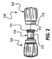
キャップ102および104は、図2において、相互から分離されて、または分断状態で示されており、キャップ104は、挿入可能または雄セクション109を有するものとして示されている。セクション109は、外部に配置されたネジ山付きセグメント112で終端する細長い部分110を有する。ネジ山付きセグメント112は、キャップ102の中へ螺合することによって挿入および接合されるようにサイズ決定および成形されるネジ山114を備える。   Caps 102 and 104 are shown in FIG. 2 as being separated from each other or in a disconnected state, and cap 104 is shown as having an insertable or male section 109. Section 109 has an elongated portion 110 that terminates in an externally disposed threaded segment 112. The threaded segment 112 includes a thread 114 that is sized and shaped to be inserted and joined by threading into the cap 102.

図3に示されるようなキャップ102は、ネジ山122を含む内部に配置されたネジ山付きセグメント120を露出するように、近位端118で外向きに開く、消毒空洞またはチャンバとも呼ばれ得る閉じた中空内部116を有する。ネジ山122は、キャップ104とのネジまたは押込緊密嵌合のために、キャップ104のネジ山114に補完的に係合するサイズおよびピッチである。   The cap 102 as shown in FIG. 3 may also be referred to as a disinfection cavity or chamber that opens outwardly at the proximal end 118 to expose the internally disposed threaded segment 120 that includes the thread 122. It has a closed hollow interior 116. The thread 122 is sized and pitched to complementarily engage the thread 114 of the cap 104 for a screw or indentation tight fit with the cap 104.

図4に図示されるように、キャップ102は、内面124、開放縁126、および外面128を有し、開放縁126は、内面124と外面128との間にある共通のリンクである。さらに、ネジ山122はまた、例えば、雌ルアーコネクタ132等の雌コネクタの螺合可能セクション130に係合するサイズおよびピッチも有する。そのようなコネクタは、概して、および一般的に、医療用途においてカテーテルおよび他の流体密保護コネクタとして使用されている。図4に見られるように、キャップ102は、螺合可能セクション130が係合し、キャップ102のネジ山122との確実であるが解放可能な接続に引き込まれるとすぐに、コネクタ132(矢印134の方向に変位させられている)の周囲に包まれたときのコネクタ132のための保護カバーを提供する。   As shown in FIG. 4, the cap 102 has an inner surface 124, an open edge 126, and an outer surface 128, and the open edge 126 is a common link between the inner surface 124 and the outer surface 128. In addition, the threads 122 also have a size and pitch that engages a threadable section 130 of a female connector, such as, for example, a female luer connector 132. Such connectors are generally and generally used as catheters and other fluid tight protective connectors in medical applications. As seen in FIG. 4, the cap 102 is connected to the connector 132 (arrow 134) as soon as the threadable section 130 engages and is pulled into a secure but releasable connection with the thread 122 of the cap 102. Providing a protective cover for the connector 132 when wrapped around the

一部の実施形態において、コネクタ132は、無針注射ポート、ハブ、弁、またはデバイス、あるいは無針アクセス部位、ポート、ハブ、弁、またはデバイスと呼ばれることがあってもよく、例えば、Clave(登録商標)(ICU Medical,Inc.から入手可能)、SmartSite(登録商標)(Cardinal Health,Inc.から入手可能)、およびQ−SyteTM(Becton,Dickinson and Companyから入手可能)等のブランドを含むことができる、無針注射部位を備える。言い換えれば、一部の実施形態において、キャップ102は、以前に記載されたもの等の種々の異なる無針注射部位のうちのいずれかと好適に接続することができる。ある実施形態において、いったんキャップ102がコネクタ132に適用されるか、またはコネクタ132と連結されると、コネクタ132がキャップ102と連結されている間に非汚染状態で保たれるので、別のコネクタとコネクタ132との各再接続の前に、コネクタ132を消毒する(例えば、アルコール消毒綿で処置する)必要はない。したがって、キャップ102の使用は、標準のスワビングプロトコルに取って代わることができる。 In some embodiments, the connector 132 may be referred to as a needleless injection port, hub, valve, or device, or a needleless access site, port, hub, valve, or device, for example, Clave ( Includes brands such as (registered trademark) (available from ICU Medical, Inc.), SmartSite (registered trademark) (available from Cardinal Health, Inc.), and Q-Site (available from Becton, Dickinson and Company) A needle-free injection site is provided. In other words, in some embodiments, the cap 102 can be suitably connected to any of a variety of different needleless injection sites, such as those previously described. In some embodiments, once the cap 102 is applied to the connector 132 or coupled to the connector 132, the connector 132 is kept uncontaminated while coupled to the cap 102, thus providing another connector. There is no need to sanitize connector 132 (eg, treat with alcohol sanitized cotton) prior to each reconnection of connector to connector 132. Thus, the use of cap 102 can replace a standard swab protocol.

図5に見られるように、キャップ104のネジ山114は、雄ルアーロックコネクタ136のネジ山138に係合するサイズおよびピッチである。例えば、コネクタ136は、静脈内カテーテル無針注射部位から断絶される静脈内管セットの端部を備えることができる。キャップ104は、キャップ104がコネクタ136に係合するように矢印144の方向に変位させられるとコネクタ136の雄突起部141が簡便にしっかりと挿入される、消毒チャンバとも呼ばれ得る内側に配置された細長い穴140を有することに留意されたい。雄突起部141は、任意の好適な種類であってもよい。「雄突起部」という用語は、本明細書において広く使用され、任意の細長い構造を含む。図示した実施形態において、雄突起部141は、切頭円錐形ルアー142を備える。   As seen in FIG. 5, the threads 114 of the cap 104 are sized and pitched to engage the threads 138 of the male luer lock connector 136. For example, the connector 136 can comprise the end of an intravenous tube set that is disconnected from the intravenous catheter needleless injection site. The cap 104 is disposed inside, which may also be referred to as a disinfection chamber, where the male protrusion 141 of the connector 136 is simply and securely inserted when the cap 104 is displaced in the direction of arrow 144 so that the cap 104 engages the connector 136. Note that it has an elongated hole 140. The male protrusion 141 may be of any suitable type. The term “male protrusion” is used broadly herein and includes any elongated structure. In the illustrated embodiment, the male protrusion 141 includes a frustoconical luer 142.

キャップ104はまた、円形縁148まで続く表面146も有する。さらに、円形縁148から遠位に変位させられると、表面146は、そこから外面152に接合される円形のリング状縁150で突然終端する。キャップ102がアセンブリ100を構築するためにキャップ104に付加されると、開放縁126(図4を参照)およびリング状縁150は、界面106(図1を参照)を形成するように組み合わさることに留意されてもよい。また、ある実施形態において、コネクタ132またはコネクタ136等のコネクタの内面に接触するアセンブリ100の表面は、その内面を汚染しないように十分滅菌状態または無菌状態であることに留意されたい。   The cap 104 also has a surface 146 that extends to the circular edge 148. Further, when displaced distally from the circular edge 148, the surface 146 suddenly terminates at a circular ring-shaped edge 150 joined thereto to the outer surface 152. When cap 102 is added to cap 104 to build assembly 100, open edge 126 (see FIG. 4) and ring-like edge 150 combine to form interface 106 (see FIG. 1). May be noted. It should also be noted that in certain embodiments, the surface of assembly 100 that contacts the inner surface of a connector, such as connector 132 or connector 136, is sufficiently sterilized or aseptic so as not to contaminate the inner surface.

キャップ102および104の内部部分および関連縁を事前に滅菌し、そして使用するまでに維持することができる。キャップ102および104は、使用するために開かれる前にキャップ102がキャップ104と入れ子になっている間に、ポリプロピレン、または滅菌することができ、汚染物質を通さない他の材料を使用して、射出成形されてもよい。キャップ102および104は、抗菌物質によって含浸または被覆することができる。実施例として、各キャップ102およびキャップ104は、最終組立前にエチレンオキシド(ETO)によって個別に滅菌され、無菌状態で対にされてもよく、またはアセンブリ100は、単一のユニットとして最終的に合併され、次いで、放射線(例えば、ガンマ)等によって滅菌されてもよい。アセンブリ100は、使用時まで原型を保つことができ、入れ子部品102および104の内面は、アセンブリ100が使用するために開かれるまで、清浄かつ滅菌状態のままである。   The internal portions and associated edges of caps 102 and 104 can be pre-sterilized and maintained before use. Caps 102 and 104 can be sterilized and other materials that are impervious to contaminants while cap 102 is nested with cap 104 before being opened for use, It may be injection molded. Caps 102 and 104 can be impregnated or coated with an antimicrobial substance. As an example, each cap 102 and cap 104 may be individually sterilized with ethylene oxide (ETO) and paired in an aseptic condition prior to final assembly, or assembly 100 may eventually be merged as a single unit. And then sterilized by radiation (eg, gamma) or the like. The assembly 100 can remain intact until in use, and the inner surfaces of the nested parts 102 and 104 remain clean and sterile until the assembly 100 is opened for use.

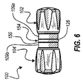
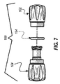
ここで、キャップ102および104の内面汚染に対してさらに別の障壁を提供するために、Oリング等のシールが表面126および150の間に配置される、図6から7Bを参照する。図6に見られるように、Oリング154は、それにより密封を提供するように表面126と150との間に配置される。Oリング154は、図7に図示されるように、キャップ102および104から変位させられることができるが、Oリング154は、キャップ102および104のうちの1つに付加されたままとなるように適合できることが予想される。例えば、図7Aに図示されるように、Oリング154は、図7に見られるように、キャップ104がキャップ102から変位させられたときに分離されるよりもむしろ、キャップ102と104とが相互から断絶されたときにキャップ104上の表面150に隣接して載置されたままとなることができる。   Reference is now made to FIGS. 6-7B, in which a seal, such as an O-ring, is disposed between the surfaces 126 and 150 to provide yet another barrier against internal contamination of the caps 102 and 104. As seen in FIG. 6, O-ring 154 is disposed between surfaces 126 and 150 so as to provide a seal. The O-ring 154 can be displaced from the caps 102 and 104 as illustrated in FIG. 7, but the O-ring 154 remains attached to one of the caps 102 and 104. It is expected that it can be adapted. For example, as shown in FIG. 7A, the O-ring 154 may be coupled to the caps 102 and 104, rather than being separated when the cap 104 is displaced from the cap 102, as seen in FIG. Can remain mounted adjacent to the surface 150 on the cap 104 when disconnected.

代替として、図7Bに示されるように、Oリング154は、キャップ102と関連付けられることができる。具体的には、キャップ102の開放縁126は、その中にOリング154を受容するための環状溝156を有することができる。環状溝156は、キャップ102がそれに連結されると、Oリング154がキャップ104または医療用コネクタに密封係合するように、サイズ決定および成形することができる。環状溝156は、図7Bに図示されるように、キャップ102の外部に向かう開放縁126の中に配置されることができるか、または、環状溝126は、キャップ102の内部に向かう開放縁126の中に配置することができることが理解されるであろう。いくつかの例示的実施形態において、キャップ102の開放縁126は、その中に環状溝126がない。そのような実施形態においては、Oリング154は、開放縁126に直接載置することができる。Oリング154は、糊等の接着剤、機械的締結具、または摩擦固定具等の使用を含む、任意の好適な方式で、キャップ102または104の上に、あるいはそれに載置することができる。   Alternatively, O-ring 154 can be associated with cap 102, as shown in FIG. 7B. Specifically, the open edge 126 of the cap 102 can have an annular groove 156 for receiving an O-ring 154 therein. The annular groove 156 can be sized and shaped such that the O-ring 154 sealingly engages the cap 104 or medical connector when the cap 102 is coupled thereto. The annular groove 156 can be disposed in the open edge 126 towards the outside of the cap 102, as shown in FIG. 7B, or the annular groove 126 can be the open edge 126 towards the inside of the cap 102. It will be understood that they can be placed in In some exemplary embodiments, the open edge 126 of the cap 102 does not have an annular groove 126 therein. In such embodiments, the O-ring 154 can rest directly on the open edge 126. The O-ring 154 can be mounted on or on the cap 102 or 104 in any suitable manner, including the use of adhesives such as glue, mechanical fasteners, or friction fasteners.

キャップ102と104との間のシールは、キャップ102または104のうちの1つの上に載置されたOリングとして説明されているが、他のシールが企図されることが理解されるであろう。例えば、キャップ102および104のそれぞれは、その上に載置されたOリングを有することができる。そのような構成において、2つのOリングは、キャップ102および104が一緒に連結されるときに相互に隣接し、それにより、キャップ102および104の内面および外面を無菌状態で区切るシールを形成する。代替的実施形態において、Oリングまたは他の密封機構を表面109aおよび109bの上に載置することができる。代替として、キャップ102および104の一方または両方は、キャップ102および104が相互に連結されるか、または別々に、医療用コネクタに連結されるときに密封機能を提供する、リップ、段差、または溝を伴って形成することができる。1つの例示的実施形態において、キャップ102および104のうちの1つは、その界面接触面の周囲に延在する隆起を有し、他方のキャップは、密封を生成するためにその中に隆起が受容される、その界面接触面の中に対応する溝を有する。さらに別の例示的実施形態において、キャップ102および104の一方または両方は、任意の既知で好適なオーバーモールドまたはコーモールドプロセスを用いてオーバーモールドまたはコーモールドされることができる。例えば、キャップ102および104の一方または両方、ならびに関連表面126および150をオーバーモールドまたはコーモールドすることができる。したがって、キャップ102および104は、ポリマーで形成することができ、表面126および150は、残りのキャップ102または104にコーモールドまたはオーバーモールドされるより軟質のポリマーによって形成されることができる。したがって、より軟質のポリマーによって形成される表面126および150は、キャップ102および104が一緒に連結されるか、または分離された医療用コネクタに連結されるときに、不透性密封を生成するように十分に圧縮または変形させることができる。さらなる実施形態に関して以下で論議されるもの等の、他の好適な密封または密封機構も可能である。   While the seal between the caps 102 and 104 is described as an O-ring mounted on one of the caps 102 or 104, it will be understood that other seals are contemplated. . For example, each of the caps 102 and 104 can have an O-ring mounted thereon. In such a configuration, the two O-rings are adjacent to each other when the caps 102 and 104 are connected together, thereby forming a seal that aseptically separates the inner and outer surfaces of the caps 102 and 104. In alternative embodiments, O-rings or other sealing mechanisms can be placed over the surfaces 109a and 109b. Alternatively, one or both of the caps 102 and 104 are lip, step or groove that provide a sealing function when the caps 102 and 104 are connected to each other or separately to the medical connector. Can be formed. In one exemplary embodiment, one of the caps 102 and 104 has a ridge that extends around its interface interface and the other cap has a ridge in it to create a seal. It has a corresponding groove in its interface contact surface to be received. In yet another exemplary embodiment, one or both of caps 102 and 104 can be overmolded or comolded using any known and suitable overmolding or comolding process. For example, one or both of caps 102 and 104 and associated surfaces 126 and 150 can be overmolded or comolded. Thus, the caps 102 and 104 can be formed of a polymer and the surfaces 126 and 150 can be formed of a softer polymer that is co-molded or overmolded to the remaining cap 102 or 104. Thus, the surfaces 126 and 150 formed by the softer polymer will create an impermeable seal when the caps 102 and 104 are connected together or connected to a separate medical connector. Can be fully compressed or deformed. Other suitable sealing or sealing mechanisms are possible, such as those discussed below with respect to further embodiments.

本明細書の他の場所で記述されるように、キャップ102および104が一緒に連結されたときに、キャップ102および104内に配置された消毒剤の蒸発または損失を制限または防止するために、密封機構を使用することができる。加えて、本明細書で説明されるような密封機構はまた、キャップ102および104が分離された医療用コネクタに連結されたときに、キャップ102および104内に配置された消毒剤の蒸発または損失を制限または防止することもできる。さらに、密封機構は、相互に連結されたときにキャップ102および104内への、またはキャップ102および104が分離された医療用コネクタに別個に連結されたときに、キャップ102および104内への微生物の進入を制限または防止することができる。また、密封機構は、キャップ102および104が所定の時間量にわたって相互に連結、または分離された医療用コネクタに連結されたときに、キャップ102および104内に消毒剤を維持するように構成することができる。したがって、密封は、キャップ102および104が一緒に連結されたとき、またはキャップ102および104が分離された医療用コネクタに連結されたときに、キャップ102および104内に配置された消毒剤の蒸発を部分的または完全に防止しながらも、微生物の進入を制限または防止するように適合され得る。同様に、密封は、キャップ102および104内に配置された消毒剤の蒸発を防止することなく、微生物の進入を制限または防止するように適合されてもよい。さらに他の実施形態において、一緒に連結されたときにキャップ102と104との間に、または分離された医療用コネクタに連結されたときにキャップ102と104との間に、密封が提供されない。   As described elsewhere herein, to limit or prevent evaporation or loss of the disinfectant disposed within caps 102 and 104 when the caps 102 and 104 are coupled together, A sealing mechanism can be used. In addition, the sealing mechanism as described herein may also cause evaporation or loss of the disinfectant disposed within the caps 102 and 104 when the caps 102 and 104 are coupled to separate medical connectors. Can also be restricted or prevented. In addition, the sealing mechanism may include microorganisms into the caps 102 and 104 when coupled together or into the caps 102 and 104 when the caps 102 and 104 are separately coupled to separate medical connectors. Can be restricted or prevented. The sealing mechanism may also be configured to maintain a disinfectant within the caps 102 and 104 when the caps 102 and 104 are connected to a medical connector that is connected to or separated from each other for a predetermined amount of time. Can do. Thus, the seal prevents evaporation of the disinfectant disposed within the caps 102 and 104 when the caps 102 and 104 are coupled together or when the caps 102 and 104 are coupled to separate medical connectors. It can be adapted to limit or prevent microbial entry while partially or completely preventing. Similarly, the seal may be adapted to limit or prevent microbial entry without preventing evaporation of the disinfectant disposed within the caps 102 and 104. In yet other embodiments, no seal is provided between the caps 102 and 104 when coupled together or between the caps 102 and 104 when coupled to a separate medical connector.

図8Aに見られるテープ158等の密封テープ、または平面あるいはフォイルシールによって、内面汚染に対する密封におけるさらなる安全性が提供されてもよい。テープ158は、表面126および150の露出縁を完全に覆うように配置される。テープ158は、例えば、金属化表面マイラー等の不浸透性柔軟材料であってもよい。図8Bに見られるように、テープ158は、確実な密封を提供するように表面126および150に巻き付けられる。キャップ102および104の分離を容易にし、密封が破られたという可視的な表示を提供するために、キャップ102がキャップ104から分離されたときに、テープ158が脆く分かれることが好ましい。したがって、テープ158は、使用前には、微生物の進入を防止する密封と、キャップ102と104との間の確実な接続を維持するための機構との両方を提供する。しかしながら、使用前にキャップ102と104との間の確実な接続を維持するために、任意の好適な密封機構を使用できることが理解されるであろう。例えば、しっかりと選択的にキャップ102と104とを一緒に連結し、密封を破るためには慎重な動作を必要とし、密封が破られたかどうかという視覚的表示を提供する任意の密封機構を使用することができる。限定ではなく一例として、好適な密封機構は、ヒートステーク、摩擦密封、鉤付き密封、歯止め密封、および同等物を含んでもよい。   Additional safety in sealing against internal contamination may be provided by a sealing tape, such as tape 158 seen in FIG. 8A, or a planar or foil seal. Tape 158 is positioned to completely cover the exposed edges of surfaces 126 and 150. The tape 158 may be, for example, an impermeable flexible material such as a metalized surface mylar. As seen in FIG. 8B, tape 158 is wrapped around surfaces 126 and 150 to provide a secure seal. To facilitate the separation of caps 102 and 104 and provide a visual indication that the seal has been broken, it is preferred that tape 158 break apart when cap 102 is separated from cap 104. Thus, the tape 158 provides both a seal that prevents entry of microorganisms and a mechanism for maintaining a secure connection between the caps 102 and 104 prior to use. However, it will be appreciated that any suitable sealing mechanism can be used to maintain a secure connection between the caps 102 and 104 prior to use. For example, use any sealing mechanism that securely and selectively connects caps 102 and 104 together, requires careful action to break the seal, and provides a visual indication of whether the seal has been broken can do. By way of example and not limitation, suitable sealing mechanisms may include heat stakes, friction seals, hooked seals, pawl seals, and the like.

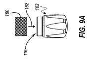
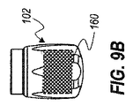
断絶された医療用コネクタを冠着するときに、単にコネクタを覆う以上のことをすることが望ましくなり得る。例えば、矢印162によって示されるように、パッド160をキャップ102の中へと変位させること等によって、図9Aに見られるパッド160等の吸着性パッドが、キャップ102内(例えば、消毒チャンバ116内)に含まれ得る。パッド160は、図9Bにおいてキャップ102の中に配置された状態で見えている。消毒剤164も、図9Cに図示されるように、キャップ102内に配置することができる。消毒剤164は、液体または固体の形態であり得る。例えば、アルコールまたは別の安定した液体消毒剤が、所定の濃度レベルまでパッド160の中に受容されるか、パッド160を湿潤させるか、浸すか、または飽和させるように、容器166から添加されてもよい。いったんアセンブリ100が完全に組み立てられると、パッド160は、本明細書において説明されるように、アセンブリ100に提供される外部密封によって、所定の濃度レベルで実質的にとどまることに留意されたい。代替として、または加えて、パッド160は、例えば、グルコン酸クロルヘキシジン等の乾燥消毒剤を受容するか、またはそれが含浸されてもよい。   When crowning a disconnected medical connector, it may be desirable to do more than just cover the connector. For example, an absorptive pad, such as the pad 160 seen in FIG. 9A, may be placed in the cap 102 (eg, in the disinfection chamber 116), such as by displacing the pad 160 into the cap 102, as indicated by arrow 162. Can be included. The pad 160 is visible in the state of being placed in the cap 102 in FIG. 9B. A disinfectant 164 can also be placed in the cap 102 as illustrated in FIG. 9C. The disinfectant 164 can be in liquid or solid form. For example, alcohol or another stable liquid disinfectant is added from the container 166 to be received into the pad 160 to a predetermined concentration level, or to wet, dip or saturate the pad 160. Also good. It should be noted that once the assembly 100 is fully assembled, the pad 160 remains substantially at a predetermined concentration level due to the external seal provided to the assembly 100 as described herein. Alternatively or in addition, pad 160 may receive or be impregnated with a dry disinfectant such as, for example, chlorhexidine gluconate.

さらに、図9Dに示されるように、いったんキャップ104がキャップ102にしっかりと付加されると、パッド160は、少なくとも円形縁148に接触するように配置されることに留意されたい(図5も参照)。(図9Dにおいて、アセンブリ100の内部にあるキャップ104の部品は、隠線または破線で見られる。)そのような接触は、接触が関連コネクタと行われる前に表面と接触することが好まれる拭き取り動作を提供する。また、清掃および/または消毒目的で、キャップ104の関連内面上の残留消毒剤が、関連コネクタの関連部品に移送され得ることにも留意されたい。   Further, as shown in FIG. 9D, note that once the cap 104 is firmly attached to the cap 102, the pad 160 is positioned to contact at least the circular edge 148 (see also FIG. 5). ). (In FIG. 9D, the parts of the cap 104 inside the assembly 100 are seen in hidden or dashed lines.) Such contact is a wipe that is preferred to contact the surface before contact is made with the associated connector. Provide behavior. It should also be noted that for cleaning and / or disinfection purposes, residual disinfectant on the associated inner surface of the cap 104 can be transferred to the associated part of the associated connector.

パッド160は、キャップ104がキャップ102に連結されると、図9Dに図示されるように、細長い部分110がキャップ102内のパッド160を圧縮することができるように、変形可能な弾力性材料で形成することができる。さらに、パッド160は、キャップ104がキャップ102から除去されたときに、その元の形状に拡張することができる。同様に、パッド160は、キャップ102が医療用コネクタ132等の医療用コネクタに連結されたときに、キャップ102内で圧縮することができる。より具体的には、医療用コネクタへのキャップ102の接続中に、キャップ102およびパッド160は、医療用コネクタの開放縁に対して回転し、それにより、医療用コネクタをキャップ102の中へ引き込む。キャップ102の回転は、パッド160に、医療用コネクタの開放縁を拭き取らせるか、または磨きあげさせる。したがって、キャップ102内に配置されたパッド160および任意の消毒剤は、医療用コネクタの開放縁を浄化および消毒することができる。パッド160はまた、パッド160が医療用コネクタの開放縁および/またはネジ山の周囲に延在するように、医療用コネクタがキャップ102に連結されるとパッド160が変形されるように形成することもできる。例えば、パッド160は、キャップ102が医療用コネクタ132の上にねじられると、パッド160が医療用コネクタ132のネジ山130および/または開放縁の周囲で変形し、それにより、医療用コネクタ132のネジ山130および/または開放縁を磨きあげるように形成することができる。   The pad 160 is made of a deformable resilient material so that when the cap 104 is coupled to the cap 102, the elongated portion 110 can compress the pad 160 within the cap 102, as illustrated in FIG. 9D. Can be formed. Further, the pad 160 can expand to its original shape when the cap 104 is removed from the cap 102. Similarly, the pad 160 can be compressed within the cap 102 when the cap 102 is coupled to a medical connector, such as the medical connector 132. More specifically, during connection of cap 102 to the medical connector, cap 102 and pad 160 rotate relative to the open edge of the medical connector, thereby drawing the medical connector into cap 102. . The rotation of the cap 102 causes the pad 160 to wipe or polish the open edge of the medical connector. Thus, the pad 160 and any disinfectant disposed within the cap 102 can clean and disinfect the open edge of the medical connector. The pad 160 is also configured such that the pad 160 is deformed when the medical connector is coupled to the cap 102 such that the pad 160 extends around the open edge and / or thread of the medical connector. You can also. For example, the pad 160 may deform around the thread 130 and / or the open edge of the medical connector 132 when the cap 102 is twisted over the medical connector 132, thereby causing the medical connector 132 to The thread 130 and / or the open edge can be shaped to be polished.

パッド160はまた、液体消毒剤がキャップ102内に配置されたときに付加的な機能性を提供することもできる。具体的には、パッド160は、キャップ104内の液体消毒剤を吸収または放出するスポンジの役割を果たす。より具体的には、パッド160がキャップ104の細長い部分110(図9D、図14のパッド160を圧縮する細長い部分268も参照)またはキャップ102に連結された医療用コネクタの開放縁によって圧縮されると、パッド160は、消毒剤を医療用コネクタの細長い部分110または開放縁に移送することができるように、消毒剤の少なくとも一部分を放出する。逆に、キャップ102または医療用コネクタがキャップ102から断絶されると、パッド160は、拡張し、消毒剤がキャップ102から滴り出ないように、または溢れ出ないように過剰な消毒剤を吸収する。   The pad 160 can also provide additional functionality when a liquid disinfectant is placed in the cap 102. Specifically, the pad 160 serves as a sponge that absorbs or releases the liquid disinfectant in the cap 104. More specifically, the pad 160 is compressed by the elongate portion 110 of the cap 104 (see also elongate portion 268 compressing the pad 160 of FIG. 9D) or the open edge of the medical connector coupled to the cap 102. The pad 160 then releases at least a portion of the disinfectant so that the disinfectant can be transferred to the elongated portion 110 or open edge of the medical connector. Conversely, when the cap 102 or medical connector is disconnected from the cap 102, the pad 160 expands and absorbs excess disinfectant so that the disinfectant does not drip out of the cap 102 or overflow. .

キャップ102内に配置されたパッド160および消毒剤164と同様に、キャップ104も、その中にパッドおよび/または消毒剤が配置されてもよい。例えば、図9Eに図示されるように、パッド170は、キャップ104の細長い穴140の内側に配置されてもよい。消毒剤はまた、キャップ102の中の消毒剤164と同様に、キャップ104内に配置されることもできる。消毒剤は、液体または固体の形態であり得る。例えば、アルコールまたは別の安定した液体消毒剤が、所定のレベルまでパッド170を飽和させるように容器から添加されてもよい。代替として、または加えて、パッド170は、グルコン酸クロルヘキシジン等の乾燥消毒剤で含浸されてもよい。いったんアセンブリ100が完全に組み立てられると、キャップ104内に配置された消毒剤で飽和したパッド170は、上記で説明されたように、アセンブリ100のための外部密封によって、所定の飽和レベルで実質的にとどまることに留意されたい。いったんキャップ102と104とが相互から断絶され、別個の医療用コネクタに接続されると、キャップ104内に配置されたパッド170は、清掃および/または消毒目的で、関連コネクタの関連部品を磨きあげ得る。しかしながら、一部の実施形態において、パッド170は、キャップ104に連結された医療用コネクタに接触しなくてもよいことが理解されるであろう。加えて、キャップ104内に配置された消毒剤は、清掃および/または消毒目的で、関連医療用コネクタの関連部品に移送されてもよい。   Similar to the pad 160 and disinfectant 164 disposed within the cap 102, the cap 104 may have a pad and / or disinfectant disposed therein. For example, as illustrated in FIG. 9E, the pad 170 may be disposed inside the elongated hole 140 of the cap 104. A disinfectant can also be placed in the cap 104, similar to the disinfectant 164 in the cap 102. The disinfectant can be in liquid or solid form. For example, alcohol or another stable liquid disinfectant may be added from the container to saturate the pad 170 to a predetermined level. Alternatively or additionally, the pad 170 may be impregnated with a dry disinfectant such as chlorhexidine gluconate. Once the assembly 100 is fully assembled, the sanitizer-saturated pad 170 disposed within the cap 104 is substantially at a predetermined saturation level by an external seal for the assembly 100, as described above. Please note that the Once the caps 102 and 104 are disconnected from each other and connected to separate medical connectors, the pads 170 disposed within the cap 104 can polish the relevant parts of the relevant connector for cleaning and / or disinfection purposes. . However, it will be appreciated that in some embodiments, the pad 170 may not contact a medical connector coupled to the cap 104. In addition, the disinfectant disposed within the cap 104 may be transferred to an associated part of the associated medical connector for cleaning and / or disinfection purposes.

キャップ102、104等のキャップの付加的な実施形態が、参照することにより本明細書に組み込まれる2008年7月11日に出願され、2009年3月5日に米国特許出願公開第2009/0062766号として公開された「STERILITY−PROTECTING CAPS WITH FLUID RESERVOIR FOR SEPARATED CONNECTORS」と題された米国特許出願第12/171,997号の図10−29および関連明細書とで提供されている。公報で示されるように、キャップ102と同様の雌型キャップに関して説明される、公報の図16−29の例示的実施形態の任意の好適な特徴が、キャップ104と同様の雄型キャップに適用されるか、または組み込まれてもよい。同様に、公報の図16−29を参照して説明される雌型キャップは、キャップ102、104が相互に入れ子になるキャップ102および104を参照して説明されるものと同様に、雄型キャップに連結することができる。他の実施形態において、雄のタイプであろうと雌のタイプであろうと、公報の図1−29に関して説明されるキャップの任意の好適な特徴を補完キャップと入れ子になるか、または別様に関連付けられることなく、形成および/または採用することができる。   Additional embodiments of caps, such as caps 102, 104, were filed on Jul. 11, 2008, which is incorporated herein by reference, and U.S. Patent Application Publication No. 2009/0062766 on Mar. 5, 2009. 10-29 of US patent application Ser. No. 12 / 171,997 entitled “STERILITY-PROTECTING CAPS WITH FLUID RESERVOR FOR FOR SEPARATED CONNECTORS” and related specification. As shown in the publication, any suitable feature of the exemplary embodiment of FIGS. 16-29 of the publication described with respect to a female cap similar to the cap 102 applies to a male cap similar to the cap 104. Or may be incorporated. Similarly, the female cap described with reference to FIGS. 16-29 of the publication is similar to that described with reference to caps 102 and 104 in which caps 102 and 104 are nested with each other. Can be linked to. In other embodiments, whether male or female type, any suitable feature of the cap described with respect to FIGS. 1-29 of the publication may be nested or otherwise associated with the complementary cap. Can be formed and / or employed without being.

以降において、上記で説明されたキャップ102、104および公報において説明される他のキャップのものとは、ある点で異なる連結配設および/または他の特徴を有することができるキャップの付加的な実施形態を論議する。そのようなキャップの任意の好適な特徴は、以降で説明されるキャップに組み込むことができ、逆もまた同様である。   In the following, additional implementations of caps that may have different coupling arrangements and / or other features in certain respects than those of caps 102, 104 described above and other caps described in the publication. Discuss the form. Any suitable feature of such a cap can be incorporated into the cap described below and vice versa.

図10および11は、第1の保護医療用コネクタ、遮蔽体、またはキャップ1002、第2の保護医療用コネクタ、遮蔽体、またはキャップ1004を含む、システムまたはアセンブリ1000を示している。図10に示されるように、キャップ1002、1004は、アセンブリ1000が出荷または使用前状態であるときに相互に接続される。図11に示されるように、キャップ1002、1004は、それぞれが対応または補完医療用コネクタと連結されてもよいように、相互から分離することができる。例えば、キャップ102と同様に、キャップ1002は、雌ルアーロックまたは無針注射部位等の雌コネクタと連結されるように構成することができる(例えば、図4参照)。したがって、キャップ1002は、雌キャップと呼ばれてもよい。キャップ104と同様に、キャップ1004は、雄ルアーロック等の雄コネクタと連結されるように構成することができる(例えば、図5参照)。したがって、キャップ1004は、雄キャップと呼ばれてもよい。   FIGS. 10 and 11 illustrate a system or assembly 1000 that includes a first protective medical connector, shield, or cap 1002 and a second protective medical connector, shield, or cap 1004. As shown in FIG. 10, the caps 1002, 1004 are connected to each other when the assembly 1000 is in a shipping or pre-use state. As shown in FIG. 11, the caps 1002, 1004 can be separated from each other so that each may be coupled with a corresponding or complementary medical connector. For example, similar to the cap 102, the cap 1002 can be configured to be coupled to a female connector such as a female luer lock or needle-free injection site (see, eg, FIG. 4). Accordingly, the cap 1002 may be referred to as a female cap. Similar to the cap 104, the cap 1004 can be configured to be coupled to a male connector such as a male luer lock (see, eg, FIG. 5). Accordingly, the cap 1004 may be referred to as a male cap.

図10および11を引き続き参照すると、キャップ1002は、筐体1010を備えることができる。筐体1010は、細長くあり得て、円筒または任意の他の好適な形状を画定してもよい。例えば、図示した実施形態において、筐体1010は、実質的に円筒形の外面1014を画定する側壁1012を含む。外面は、示されるように平滑となり得て、キャップ1002が医療用コネクタと連結された場合に患者に接触すると、患者にとっての快適性を増進することができる。他の実施形態において、外面は、キャップ1002、1004の分離を可能にするために、キャップ1004に対してキャップ1002を回転させること、および/または医療用コネクタに対してキャップ1002を回転させることに役立つことができる把持特徴を含むことができる。そのような把持特徴は、例えば、上記で説明された隆起105、溝107、および突起部108と同様の隆起、溝、および/または突起部、および/または比較的高い摩擦係数を有する弾力性あるいは他の被覆あるいは層を含むことができる。側壁1012は、その一端において密封表面1016を画定することができ、その反対端において末端縁1018を画定することができる。   With continued reference to FIGS. 10 and 11, the cap 1002 can include a housing 1010. The housing 1010 may be elongated and may define a cylinder or any other suitable shape. For example, in the illustrated embodiment, the housing 1010 includes a sidewall 1012 that defines a substantially cylindrical outer surface 1014. The outer surface can be smooth as shown and can increase comfort for the patient when the cap 1002 contacts the patient when coupled with the medical connector. In other embodiments, the outer surface may rotate the cap 1002 relative to the cap 1004 and / or rotate the cap 1002 relative to the medical connector to allow separation of the caps 1002, 1004. Grip features that can be useful can be included. Such gripping features can be, for example, ridges, grooves, and / or protrusions similar to the ridges 105, grooves 107, and protrusions 108 described above, and / or elasticity having a relatively high coefficient of friction or Other coatings or layers can be included. The sidewall 1012 can define a sealing surface 1016 at one end and a terminal edge 1018 at the opposite end.

筐体1010はさらに、横断壁または隔壁1020を含むことができる。図示した実施形態において、隔壁1020は、側壁1012の長手軸と実質的に垂直である面を画定する。側壁1012の第1の部分は、隔壁1020によって一端が閉鎖され、その反対側が開いている(例えば、密封表面1016が消毒チャンバ1022の開放端を画定することができる)消毒チャンバ1022を画定するように、隔壁1020の片側と協働することができる。同様に、側壁1012の第2の部分は、同様に隔壁1020によって一端が閉鎖され、その反対側が開いている(例えば、末端縁1018が連結チャンバ1024の開放端を画定することができる)連結チャンバ1024を画定するように、隔壁1020の反対側と協働することができる。   The housing 1010 can further include a transverse wall or partition 1020. In the illustrated embodiment, the septum 1020 defines a plane that is substantially perpendicular to the longitudinal axis of the sidewall 1012. The first portion of the side wall 1012 is closed at one end by a septum 1020 and is open on the opposite side (eg, the sealing surface 1016 can define the open end of the disinfection chamber 1022) to define a disinfection chamber 1022. In addition, it can cooperate with one side of the partition wall 1020. Similarly, the second portion of the side wall 1012 is similarly connected at one end by a septum 1020 and open at the other end (eg, the distal edge 1018 can define the open end of the connection chamber 1024). It can cooperate with the opposite side of the septum 1020 to define 1024.

側壁1012の内面は、消毒チャンバ1022の領域中の接続幾何学形状または接続界面1030を含むことができる。接続界面1030は、上記で説明されたネジ山122と同様の内向きに突出するネジ山1031を備えることができ、例えば、無針注射部位の外向きに突出するネジ山等の医療用コネクタの接続界面に補完的に係合するように構成されることができる。したがって、ネジ山付き接続界面1030は、確実であるが選択的に取外し可能な様式で、医療用コネクタへのキャップ1002の選択的な連結を可能にすることができる。接続界面1030の他の構成は、摩擦嵌合、スナップ嵌合、または他の好適な界面接触配設等の確実であるが選択的に取外し可能な様式でキャップ1002が医療用コネクタと連結されることを可能にしてもよい。   The inner surface of the sidewall 1012 can include a connection geometry or connection interface 1030 in the region of the disinfection chamber 1022. The connection interface 1030 can include an inwardly projecting thread 1031 similar to the thread 122 described above, eg, a medical connector such as a thread projecting outwardly of a needleless injection site. It can be configured to complementarily engage the connection interface. Thus, the threaded connection interface 1030 can allow selective coupling of the cap 1002 to the medical connector in a secure but selectively removable manner. Other configurations of the connecting interface 1030 may couple the cap 1002 with the medical connector in a secure but selectively removable manner such as a friction fit, snap fit, or other suitable interface contact arrangement. May be possible.

消毒チャンバ1022は、その中にパッド1032を含むことができる。パッド1032は、上記で説明されたパッド160、170に類似することができる。種々の実施形態において、パッド1032は、変形可能となり得て、また、例えば、上記で説明された消毒剤164等の消毒剤1033を保持するように構成することもできる。さらなる実施形態において、パッド1032は、弾力的に変形可能であり得る。例えば、パッド1032は、弾力性発泡体、任意の開放気泡発泡体、フェルト、または不織繊維マトリクス等の任意の好適なスポンジ状材料を含むことができ、消毒チャンバ1022に導入される医療用コネクタの一部分の外形に一致するように構成することができる(例えば、無針注射部位の端部の不均一な表面、本明細書の図32−34および関連明細書も参照)。パッド1032はまた、任意の独立気泡発泡体、ならびにシリコーンまたは同等物等の固体弾力性発泡体を含むこともできる。   The disinfection chamber 1022 can include a pad 1032 therein. The pad 1032 can be similar to the pads 160, 170 described above. In various embodiments, the pad 1032 can be deformable and can be configured to hold a disinfectant 1033, such as the disinfectant 164 described above, for example. In further embodiments, the pad 1032 can be elastically deformable. For example, the pad 1032 can comprise any suitable sponge-like material, such as a resilient foam, any open cell foam, felt, or a non-woven fiber matrix, and a medical connector introduced into the disinfection chamber 1022. Can be configured to conform to the outline of a portion of (eg, non-uniform surface at the end of a needle-free injection site, see also FIGS. 32-34 and related specifications herein). The pad 1032 can also include any closed cell foam, as well as a solid resilient foam such as silicone or the like.

パッド1032は、パッド1032が拡張状態であるときに消毒剤1033を保持することができる一連の開口部または空間、あるいは開口部または空間網を有することができる。例えば、消毒剤1033は、パッド1032の少なくともわずかな部分の内部に受容する、それを占有する、充填する(または部分的に充填する)、湿潤させる、浸す、または飽和させることができ、または言い換えれば、所与の濃度レベルまでパッド1032を充填することができる。パッド1032の圧縮は、消毒剤1033をパッド1032から退出させて、医療用コネクタに接触させることができる。圧縮力の除去時の発泡体の弾力性拡張は、パッド1032が、パッド1032から以前に押し出されていた消毒剤1033の少なくともいくらかを吸い上げるか、または吸収することを可能にすることができる。一部の実施形態において、消毒剤1033は、50〜90%に及ぶ種々の濃度でのアルコール(例えば、イソプロピルアルコール)、50〜95%に及ぶ種々の濃度でのエタノール、およびあらゆる消毒剤とのあらゆるアルコールの組み合わせ等の任意の液体消毒剤、あるいはクロルヘキシジン、エチレンジアミン四酢酸(EDTA)、ヨードフォル、またはそれらの任意の好適な組み合わせ等の乾燥材料を含むことができる。したがって、消毒剤1033は、一連の液滴として図10に概略的に示されているが、消毒剤1033は、必ずしも液体とは限らず、示されているものよりも大きいかまたは小さい程度でパッド1032を充填してもよい。図示した実施形態において、消毒チャンバ1022が密封状態である(例えば、その使用前状態である)ときに、パッド1032は、長手方向に弛緩、拡張、または非圧縮状態である。パッド1032は、アセンブリ1000が使用前状態であるときに、1つ以上の寸法が圧縮されていなくてもよいが、1つ以上の他の寸法が圧縮されてもよいことに留意されたい。例えば、パッド1032は、アセンブリ1000が使用前状態であるときに、長手方向に拡張するか、または弛緩状態になることができるが、側壁1012を介して半径方向内向きに圧縮されることができる。長手方向へのパッド1032のそのような圧縮の不足は、キャップ1002、1004が使用前構成であるときに、キャップ1004がキャップ1002を密封するようにキャップ1002の接続界面1030と相互作用せず、したがって、キャップ1004のいずれの部分もパッド1032と接触しないという事実に起因し得る。   The pad 1032 can have a series of openings or spaces, or openings or space networks, that can hold the disinfectant 1033 when the pad 1032 is in the expanded state. For example, the disinfectant 1033 can be received, occupy, fill (or partially fill), wet, soak, or saturate inside, or in other words, at least a small portion of the pad 1032. For example, the pad 1032 can be filled to a given concentration level. Compression of the pad 1032 can cause the disinfectant 1033 to exit the pad 1032 and contact the medical connector. Elastic expansion of the foam upon removal of the compressive force can allow the pad 1032 to suck or absorb at least some of the disinfectant 1033 that was previously extruded from the pad 1032. In some embodiments, the disinfectant 1033 comprises alcohol at various concentrations ranging from 50-90% (eg, isopropyl alcohol), ethanol at various concentrations ranging from 50-95%, and any disinfectant. Any liquid disinfectant, such as any alcohol combination, or a dry material such as chlorhexidine, ethylenediaminetetraacetic acid (EDTA), iodophor, or any suitable combination thereof may be included. Thus, although the disinfectant 1033 is schematically illustrated in FIG. 10 as a series of droplets, the disinfectant 1033 is not necessarily a liquid and is padded to a greater or lesser extent than that shown. 1032 may be filled. In the illustrated embodiment, the pad 1032 is relaxed, expanded, or uncompressed in the longitudinal direction when the sterilization chamber 1022 is sealed (eg, in its pre-use state). Note that the pad 1032 may be uncompressed in one or more dimensions when the assembly 1000 is in a pre-use state, but may be compressed in one or more other dimensions. For example, the pad 1032 can expand longitudinally or become relaxed when the assembly 1000 is in a pre-use state, but can be compressed radially inward through the sidewall 1012. . Such lack of compression of the longitudinal pad 1032 does not interact with the connection interface 1030 of the cap 1002 so that the cap 1004 seals the cap 1002 when the cap 1002, 1004 is in the pre-use configuration, Thus, it can be attributed to the fact that no part of the cap 1004 contacts the pad 1032.

図示した実施形態において、パッド1032は、実質的に円筒形であり、ネジ山1031の内径とほぼ同じサイズである外径を画定する。他の実施形態において、パッド1032の外径は、消毒チャンバ1022内で半径方向に圧縮され、よりタイトに保たれるので、ネジ山1031の内径よりも大きくなり得る。さらなる実施形態において、パッド1032は、半径方向内向きに突出し、ネジ山1031に対して補完的であり、それにより、パッド1032をチャンバ1022内に固定するネジ切りを含むことができる。   In the illustrated embodiment, the pad 1032 is substantially cylindrical and defines an outer diameter that is approximately the same size as the inner diameter of the thread 1031. In other embodiments, the outer diameter of the pad 1032 can be larger than the inner diameter of the thread 1031 because it is radially compressed in the disinfection chamber 1022 and kept tighter. In a further embodiment, the pad 1032 protrudes radially inward and is complementary to the thread 1031, thereby including threading that secures the pad 1032 within the chamber 1022.

消毒チャンバ1022は、消毒チャンバ1022の開放端に跨ることができるカバー1034を介して密封表面1016で密封することができる。カバー1034は、例えば、接着剤を介する等の任意の好適な方式で、筐体1010に固定することができる。好ましくは、カバー1034は、施術者によって容易に除去することができる。例えば、一部の実施形態において、カバー1034は、タブ1035を含むことができ、施術者は、一方の手で筐体1010を支え、他方の手で筐体1010からタブ1035を引き離すことによってカバー1034を容易に除去することができる。取外し可能なカバー1034は、例えば、不浸透性の柔軟材料等の任意の好適な材料(例えば、フォイル、プラスチック、金属化表面マイラー、および同等物)で形成することができる。カバー1034は、キャップ1002の使用前に消毒チャンバ1022の滅菌状態を維持することに役立つことができ、および/または消毒チャンバ1022からの消毒剤1033の蒸発損失を防止することができる気密密封を提供することができる。   The disinfection chamber 1022 can be sealed with a sealing surface 1016 through a cover 1034 that can span the open end of the disinfection chamber 1022. The cover 1034 can be fixed to the housing 1010 by any suitable method such as through an adhesive. Preferably, the cover 1034 can be easily removed by the practitioner. For example, in some embodiments, the cover 1034 can include a tab 1035, and the practitioner covers the housing 1010 with one hand and pulls the tab 1035 away from the housing 1010 with the other hand. 1034 can be easily removed. The removable cover 1034 can be formed of any suitable material (eg, foil, plastic, metalized surface mylar, and the like), such as, for example, an impermeable flexible material. The cover 1034 can help maintain sterilization of the sterilization chamber 1022 prior to use of the cap 1002 and / or provide an airtight seal that can prevent evaporation loss of the sterilant 1033 from the sterilization chamber 1022. can do.

キャップ1002が医療用コネクタと連結されるとき、連結動作は、医療用コネクタの一部分をパッド1032と接触させることができ、上記で説明されたように、パッド1032が医療用コネクタを拭き取るか、または磨きあげることを可能にすることができる。同様に、消毒剤1033は、連結段階中に医療用コネクタと接触するように強制されることができ、キャップ1002が医療用コネクタと連結されている間、医療用コネクタと接触した状態のままでいることができる。接続界面1030は、コネクタに対する取付け構成でキャップ1002を維持するように、医療用コネクタの接続界面と協働することができる。また、接続界面1030は、消毒剤が消毒チャンバ1022から漏出することを防止するために、補完ネジ切り等を介して医療用コネクタと連結することができる。   When the cap 1002 is coupled with the medical connector, the coupling operation can cause a portion of the medical connector to contact the pad 1032 and the pad 1032 wipes the medical connector as described above, or It can make it possible to polish. Similarly, the disinfectant 1033 can be forced to contact the medical connector during the coupling phase and remain in contact with the medical connector while the cap 1002 is coupled to the medical connector. Can be. The connection interface 1030 can cooperate with the connection interface of the medical connector to maintain the cap 1002 in a mounting configuration for the connector. Also, the connection interface 1030 can be coupled with a medical connector, such as through complementary threading, to prevent the disinfectant from leaking out of the disinfection chamber 1022.

パッド1032が、完全には弾力的ではないか、あるいは(例えば、長手方向への)圧縮状態から弛緩または非圧縮状態まで遷移するために比較的長い弛緩時間を必要とする材料で形成される場合等の一部の実施形態において、少なくとも1つの寸法での弛緩または非圧縮状態における使用前保管が、パッド1032の清掃、洗浄、または消毒特性を維持または増進することができる。例えば、キャップ1002が医療用コネクタ(例えば、図4の医療用コネクタ132)と連結されると、医療用コネクタの端部は、パッド1032の近位表面(例えば、隔壁1020から最も遠い表面)と接触することができる。医療用コネクタ上へのキャップ1002のさらなる前進は、パッド1032が圧縮されるにつれて、医療用コネクタの端部の外形を補完するようにパッド1032を変形させることができ、このことは、パッド1032と医療用コネクタとの間の比較的タイトなまたは連続的な接触を可能にすることができる。図示した実施形態において、キャップ1002は、医療用コネクタ上に前進させられるにつれて、医療用コネクタに対して回転させられる。この回転運動は、パッド1032の外形表面に医療用コネクタを摩擦させる。ある実施形態において、より大量の消毒剤1033がパッド1032から放出されることとともに、パッド1032のますます大きな圧縮が、医療用コネクタのますます強い摩擦を生じさせる。したがって、パッド1032が使用前状態における少なくとも1つの寸法で(例えば、長手方向に)圧縮されておらず、したがって、塑性的に変形されないか、または圧縮前からの時間のかかる弾力性回復を受けないときに、パッド1032は、連結手順の比較的大部分にわたって医療用コネクタと消毒接触することができる。一部の実施形態において、医療用コネクタのより良好な消毒を達成するために、最初にパッド1032が非圧縮または拡張状態に弛緩することを待つ必要がないので、施術者は、キャップ1002を医療用コネクタにより迅速に連結することができる。   If the pad 1032 is not fully elastic or is formed of a material that requires a relatively long relaxation time to transition from a compressed state (eg, longitudinally) to a relaxed or uncompressed state In some embodiments, such as pre-use storage in a relaxed or uncompressed state in at least one dimension can maintain or enhance the cleaning, cleaning, or disinfecting properties of the pad 1032. For example, when the cap 1002 is coupled with a medical connector (eg, the medical connector 132 of FIG. 4), the end of the medical connector is in contact with the proximal surface of the pad 1032 (eg, the surface furthest from the septum 1020). Can touch. Further advancement of the cap 1002 over the medical connector can deform the pad 1032 to complement the contour of the end of the medical connector as the pad 1032 is compressed, which A relatively tight or continuous contact with the medical connector can be allowed. In the illustrated embodiment, the cap 1002 is rotated relative to the medical connector as it is advanced over the medical connector. This rotational movement causes the medical connector to rub against the outer surface of the pad 1032. In certain embodiments, as more disinfectant 1033 is released from the pad 1032, the increasingly greater compression of the pad 1032 causes an increasingly strong friction of the medical connector. Thus, the pad 1032 is not compressed (e.g., longitudinally) in at least one dimension in the pre-use state, and therefore is not plastically deformed or subjected to time-consuming elastic recovery from before compression. Sometimes the pad 1032 can be in sterilization contact with the medical connector over a relatively large portion of the coupling procedure. In some embodiments, the practitioner does not need to wait for the pad 1032 to relax to an uncompressed or expanded state to achieve better disinfection of the medical connector so that the practitioner can remove the cap 1002 from the medical device. The connector can be quickly connected.

キャップ1002が医療用コネクタと連結されるときに、パッド1032から放出される消毒剤1033の量を判定するように、種々のパラメータを調整することができる。例えば、医療用コネクタが消毒チャンバ1022内に受容される深さ、パッド1032内の消毒剤1033の濃度、および/またはパラメータを改変することができる。種々の実施形態において、キャップ1002が医療用コネクタと連結されるときに、消毒剤1033の約1/4以上、約1/3以上、約1/2以上、約2/3以上、または約3/4以上がパッド1032から放出される。一部の実施形態において、消毒剤1033の全て、または実質的に全てが、パッド1032から放出される。   Various parameters can be adjusted to determine the amount of disinfectant 1033 released from the pad 1032 when the cap 1002 is coupled to the medical connector. For example, the depth at which the medical connector is received within the disinfection chamber 1022, the concentration of the disinfectant 1033 within the pad 1032, and / or parameters can be modified. In various embodiments, when the cap 1002 is coupled with the medical connector, about 1/4 or more, about 1/3 or more, about 1/2 or more, about 2/3 or more, or about 3 of the disinfectant 1033. / 4 or more is released from the pad 1032. In some embodiments, all or substantially all of the disinfectant 1033 is released from the pad 1032.

図10を参照すると、側壁1012の内面は、連結チャンバ1024の領域中の別の接続幾何学形状または接続界面1040を含むことができる。接続界面1040は、キャップ1004の接続界面1042に相補的に係合するように構成することができる。例えば、図示した実施形態において、キャップ1002の接続界面1040は、内向きに突出するネジ山1041を備え、コネクタ1004の接続界面1042は、キャップ1004の外面においてそれを補完する、外向きに突出するネジ山1043備える。したがって、接続界面1040、1042は、確実であるが選択的に取外し可能な様式で、キャップ1002、1004が相互に連結されることを可能にすることができる。接続界面1040、1042の他の構成は、同様に、以下でさらに論議されるように、摩擦嵌合、スナップ嵌合、または他の好適な界面接触配設等の確実であるが選択的に取外し可能な様式で、キャップ1002、1004が相互と連結されることを可能にしてもよい。連結チャンバ1024はさらに、以下でさらに説明される弾力性ガスケット等の密封部材1044を含むことができる。   Referring to FIG. 10, the inner surface of the sidewall 1012 can include another connection geometry or connection interface 1040 in the region of the coupling chamber 1024. The connection interface 1040 can be configured to complementarily engage the connection interface 1042 of the cap 1004. For example, in the illustrated embodiment, the connection interface 1040 of the cap 1002 includes an inwardly projecting thread 1041, and the connection interface 1042 of the connector 1004 projects outwardly, complementing it on the outer surface of the cap 1004. A screw thread 1043 is provided. Accordingly, the connection interfaces 1040, 1042 can allow the caps 1002, 1004 to be coupled together in a secure but selectively removable manner. Other configurations of the connecting interfaces 1040, 1042 are similarly reliable but selectively removed, such as a friction fit, snap fit, or other suitable interface contact arrangement, as will be discussed further below. Caps 1002, 1004 may be allowed to be coupled to each other in a possible manner. The coupling chamber 1024 can further include a sealing member 1044, such as a resilient gasket, further described below.

図10および11を参照すると、雄キャップ1004は、筐体1050を備えることができる。筐体1050は、細長くなり得て、階段状の実質的に円筒形を画定してもよく、または任意の他の好適な形状を画定してもよい。例えば、図示した実施形態において、筐体1050は、実質的に円筒形である側壁1052と、側壁1052の一端における基礎壁1054とを含む。側壁1052の密封端1056は、基礎壁1054の反対側に位置することができ、消毒チャンバ1058の中への開口部を画定することができる。したがって、側壁1052および基礎壁1054は、消毒チャンバ1058を画定するように協働することができる。   Referring to FIGS. 10 and 11, the male cap 1004 can include a housing 1050. The housing 1050 may be elongated and may define a stepped substantially cylindrical shape, or may define any other suitable shape. For example, in the illustrated embodiment, the housing 1050 includes a side wall 1052 that is substantially cylindrical, and a foundation wall 1054 at one end of the side wall 1052. The sealed end 1056 of the side wall 1052 can be located on the opposite side of the base wall 1054 and can define an opening into the disinfection chamber 1058. Accordingly, the side wall 1052 and the foundation wall 1054 can cooperate to define a disinfection chamber 1058.

一部の実施形態において、筐体1050は、側壁1052から半径方向外向きに延在することができるスカート1060を含む。一部の実施形態において、スカート1060は、キャップ1004の操作のための便利な表面を提供する。例えば、一部の実施形態において、外径間の相違が、相互に対するキャップ1002、1004の把持および回転を困難にすることができるように、側壁1052の外径は、キャップ1002の側壁1012の外径よりも小さい。また、一部の実施形態において、側壁1052は、キャップ1004を把持することを困難にし得る比較的小さい外側表面積を画定する。スカートのより大きい外径および対応するより大きい表面積は、キャップ1004の把持を促進することができる。スカート1060の外面は、示されるように、平滑となり得るか、または、キャップ1002、1004の分離を許可するように、キャップ1002に対してキャップ1004を回転させること、および/または医療用コネクタに対してキャップ1004を回転させることに役立つことができる、把持特徴を含んでもよい。そのような把持特徴は、例えば、上記で説明された隆起105、溝107、および突起部108と同様の隆起、溝、および/または突起部、および/または比較的高い摩擦係数を有する弾力性あるいは他の被覆を含むことができる。   In some embodiments, the housing 1050 includes a skirt 1060 that can extend radially outward from the sidewall 1052. In some embodiments, the skirt 1060 provides a convenient surface for operation of the cap 1004. For example, in some embodiments, the outer diameter of the side wall 1052 is outside of the side wall 1012 of the cap 1002, so that differences between the outer diameters can make it difficult to grip and rotate the caps 1002, 1004 relative to each other. Smaller than the diameter. Also, in some embodiments, the sidewall 1052 defines a relatively small outer surface area that can make it difficult to grasp the cap 1004. The larger outer diameter of the skirt and the corresponding larger surface area can facilitate gripping of the cap 1004. The outer surface of the skirt 1060 can be smooth, as shown, or by rotating the cap 1004 relative to the cap 1002, and / or relative to the medical connector to allow separation of the caps 1002, 1004. Gripping features that may help to rotate the cap 1004 may be included. Such gripping features can be, for example, ridges, grooves, and / or protrusions similar to the ridges 105, grooves 107, and protrusions 108 described above, and / or elasticity having a relatively high coefficient of friction or Other coatings can be included.

一部の実施形態において、スカート1060の末端縁1062は、基礎壁1054の外面と実質的に同一平面上にあり得る。そのような実施形態のうちの特定のものにおいて、スカート1060は、アセンブリ1000の安定性を増加させることができる。例えば、アセンブリ1000は、基礎壁1054の上で直立することができ、スカート1060は、アセンブリ1000の転倒を阻止することができる。   In some embodiments, the distal edge 1062 of the skirt 1060 can be substantially flush with the outer surface of the foundation wall 1054. In certain of such embodiments, the skirt 1060 can increase the stability of the assembly 1000. For example, the assembly 1000 can stand upright on the foundation wall 1054 and the skirt 1060 can prevent the assembly 1000 from tipping over.

図10を参照すると、消毒チャンバ1058は、パッド1032等のパッド1070を含むことができる。パッド1070は、消毒チャンバ1058の中に導入される医療用コネクタの一部分(例えば、雄ルアーの外面)の外形に一致するように変形可能となり得る。パッド1070の圧縮および/または減圧は、それぞれ、パッド1032に関して上記で説明されたような方式で、消毒剤1033をパッド1070から退出させること、および/またはパッド1070によって吸収させることができる(パッド1070とともに使用される消毒剤1033は、必ずしもパッド1032とともに使用されるものと同じ消毒剤である必要はないが、そのようなものが可能であることに留意されたい)。同様に、パッド1070を介した医療用コネクタの洗浄または衛生化は、パッド1032に関して上記で説明されたような方式で進行することができる。図示した実施形態において、パッド1070は、消毒チャンバ1058が密封または使用前構成であるときに、少なくとも長手方向に弛緩または非圧縮状態である。   Referring to FIG. 10, the sterilization chamber 1058 can include a pad 1070, such as a pad 1032. The pad 1070 can be deformable to conform to the contour of a portion of the medical connector (eg, the outer surface of the male luer) that is introduced into the sterilization chamber 1058. The compression and / or decompression of the pad 1070 can be caused to dissipate the disinfectant 1033 from the pad 1070 and / or be absorbed by the pad 1070, respectively, in the manner described above with respect to the pad 1032 (pad 1070). Note that the disinfectant 1033 used in conjunction with is not necessarily the same disinfectant used in conjunction with the pad 1032, but such is possible. Similarly, cleaning or sanitization of the medical connector via pad 1070 can proceed in the manner described above with respect to pad 1032. In the illustrated embodiment, pad 1070 is at least longitudinally relaxed or uncompressed when sterilization chamber 1058 is in a sealed or pre-use configuration.

以前に論議されたように、キャップ1004は、キャップ1002の接続界面1040と相互作用することができる接続界面1042を含むことができる。接続界面1040、1042は、密封部材1044に対して緊密にキャップ1004を保持するように協働することができる。例えば、接続界面1040、1042がネジ切りを備える場合、キャップ1002に対するキャップ1004の適切な回転が、側壁1052の密封端1056を密封部材1044に隣接させることができ、同じ方向の付加的な回転が、密封部材1044を形成してもよい。密封端1056および密封部材1044は、キャップ1004の使用前に消毒チャンバ1058の滅菌状態を維持することに役立つことができ、かつ消毒チャンバ1058からの消毒剤の蒸発損失を防止することができる気密密封を形成することができる。さらなる実施形態において、筐体1010の下縁(例えば、連結チャンバ1058を画定する側壁1012の一部分の外面)および筐体1050のスカート1060の外面に接触するために、密封テープ158(図8Aおよび8B参照)等の密封テープ(図示せず)をキャップ1002、1004の周囲に載置することができる。テープは、消毒剤の蒸発損失を防止することに役立つことができ、および/またはキャップ1002、1004がそれらの初期または使用前構成から分離されているか、または別様に移動させられているかを示すことができる。例えば、一部の実施形態において、テープは、破れやすくあり得る。   As previously discussed, the cap 1004 can include a connection interface 1042 that can interact with the connection interface 1040 of the cap 1002. The connection interfaces 1040, 1042 can cooperate to hold the cap 1004 tightly against the sealing member 1044. For example, if the connection interfaces 1040, 1042 include threading, proper rotation of the cap 1004 relative to the cap 1002 can cause the sealing end 1056 of the sidewall 1052 to be adjacent to the sealing member 1044, with additional rotation in the same direction. The sealing member 1044 may be formed. The sealed end 1056 and the sealing member 1044 can help maintain the sterilization state of the sterilization chamber 1058 prior to use of the cap 1004 and can prevent loss of disinfectant evaporation from the sterilization chamber 1058. Can be formed. In a further embodiment, sealing tape 158 (FIGS. 8A and 8B) to contact the lower edge of housing 1010 (eg, the outer surface of a portion of sidewall 1012 that defines connecting chamber 1058) and the outer surface of skirt 1060 of housing 1050. Sealing tape (not shown) or the like can be placed around the caps 1002 and 1004. The tape can help prevent disinfectant evaporation loss and / or indicate whether the caps 1002, 1004 are separated from their initial or pre-use configuration or otherwise moved. be able to. For example, in some embodiments, the tape can be easily torn.

図示した実施形態において、接続界面1042は、上記で説明されたネジ山114と同様の外向きに突出するネジ山を備え、例えば、雄ルアーを包囲するスカートの内向きに突出するネジ山等の医療用コネクタの接続界面に相補的に係合するように構成されることができる。したがって、ネジ山付き接続界面1042は、確実であるが選択的に取外し可能な様式で、医療用コネクタへのキャップ1004の選択的連結を可能にすることができる。接続界面1042の他の構成は、摩擦嵌合、スナップ嵌合、または他の好適な界面接触配設等の確実であるが選択的に取外し可能な様式で、キャップ1004が医療用コネクタと連結されることを可能にしてもよい。   In the illustrated embodiment, the connection interface 1042 includes an outwardly projecting thread similar to the thread 114 described above, such as an inwardly projecting thread of a skirt that surrounds the male luer. It can be configured to complementarily engage the connection interface of the medical connector. Thus, the threaded connection interface 1042 can allow selective coupling of the cap 1004 to the medical connector in a secure but selectively removable manner. Other configurations of the connecting interface 1042 include the cap 1004 coupled to the medical connector in a secure but selectively removable manner, such as a friction fit, snap fit, or other suitable interface contact arrangement. May be possible.

図10を引き続き参照すると、使用前状態にあるアセンブリ1000の図示される実施形態の付加的な説明が提供される。以前に論議されたように各消毒チャンバ1022、1058は、別個の筐体1012、1050によって画定することができる。チャンバ1022、1058は、使用前状態において相互から隔離されることが可能にされ、または言い換えれば、チャンバ1022、1058の間に流体連通が全く存在し得ない。   With continued reference to FIG. 10, an additional description of the illustrated embodiment of the assembly 1000 in a pre-use state is provided. As previously discussed, each sterilization chamber 1022, 1058 may be defined by a separate housing 1012, 1050. The chambers 1022, 1058 can be isolated from each other in the pre-use state, or in other words, there can be no fluid communication between the chambers 1022, 1058.

キャップ1002、1004は、チャンバのうちの1つ(例えば、図示した実施形態のチャンバ1058)を密封するように協働することにより、それらの使用前構成から離れる方向のキャップ1002、1004の操作が、チャンバ1058を開封にすることができる一方、他方のチャンバ(例えば、図示した実施形態のチャンバ1022)は、キャップ1002、1004の相対的な配向と独立に密封配向にとどまることができる。キャップ1004の筐体1050の少なくとも一部分は、キャップ1002の筐体1010の一部分の中に受容することができるか、または入れ子になることができる。図示した実施形態において、パッド1032、1070が収納される消毒チャンバ1022、1058が使用前の密封状態であるときに、パッド1032は、キャップ1004からの圧縮がなく、パッド1070は、キャップ1002からの圧縮がない。   Caps 1002, 1004 cooperate to seal one of the chambers (e.g., chamber 1058 in the illustrated embodiment) to allow operation of caps 1002, 1004 away from their pre-use configuration. , Chamber 1058 can be opened, while the other chamber (eg, chamber 1022 in the illustrated embodiment) can remain in a sealed orientation independent of the relative orientation of caps 1002, 1004. At least a portion of the housing 1050 of the cap 1004 can be received or nested within a portion of the housing 1010 of the cap 1002. In the illustrated embodiment, when the disinfection chambers 1022, 1058 in which the pads 1032, 1070 are housed are in a sealed state prior to use, the pad 1032 is not compressed from the cap 1004 and the pad 1070 is removed from the cap 1002. There is no compression.

図示した実施形態において、キャップ1002、1004は、相互に実質的に同軸上にある。以前に論議されたように、キャップ1002、1004によって画定される消毒チャンバ1022、1058はそれぞれ、開放端および閉鎖端を有することができ、使用前構成において、チャンバ1022、1058は、それらの密封された開放端がキャップ1002、1004の共通軸に沿って同じ方向を向くように配向されることができる。   In the illustrated embodiment, the caps 1002, 1004 are substantially coaxial with each other. As previously discussed, the sterilization chambers 1022, 1058 defined by the caps 1002, 1004 can each have an open end and a closed end, and in a pre-use configuration, the chambers 1022, 1058 are sealed together. The open ends can be oriented to face the same direction along the common axis of the caps 1002, 1004.

図11を参照すると、医療用コネクタ(例えば、図5のコネクタ136)との使用にキャップ1004を準備するために、キャップ1002、1004は、相互から分離される。例えば、図示した実施形態において、キャップ1002、1004は、接続界面1040、1042が相互から離れるようにキャップ1002、1004を押し進め、最終的に相互から解放されるように、長手軸の周りを反対方向に回転させられる。次いで、キャップ1004は、確実であるが選択的に取外し可能な様式で、接続界面1042を介して医療用コネクタと連結することができる。   Referring to FIG. 11, to prepare cap 1004 for use with a medical connector (eg, connector 136 of FIG. 5), caps 1002, 1004 are separated from each other. For example, in the illustrated embodiment, the caps 1002, 1004 push the caps 1002, 1004 away from each other and eventually release from each other in opposite directions around the longitudinal axis. To be rotated. The cap 1004 can then be coupled to the medical connector via the connection interface 1042 in a secure but selectively removable manner.

キャップ1002は、医療用コネクタ(例えば、図4のコネクタ132)との使用に準備し、相互に対するキャップ1002、1004の連結状態と独立して医療用コネクタに接続することができる。カバー1034は、キャップ1002から除去することができ、それにより、確実であるが選択的に取外し可能な様式で、キャップ1002が接続界面1040を介して医療用コネクタと連結されることを可能にする。   The cap 1002 can be prepared for use with a medical connector (eg, the connector 132 of FIG. 4) and can be connected to the medical connector independent of the coupling of the caps 1002, 1004 to each other. The cover 1034 can be removed from the cap 1002, thereby allowing the cap 1002 to be coupled with the medical connector via the connection interface 1040 in a secure but selectively removable manner. .

キャップ1002、1004が相互と連結される、システム1000の使用前構成は、システム1000の臨床医による取扱を容易にすることができる。キャップ1002、1004は、それぞれ、雌および雄コネクタを覆うために使用されてもよいため、相互から雌および雄コネクタを分断した直後に、連結されているが、容易に分離可能な構成でキャップ1002、1004を利用可能にすることは、便利で時間を節約することができる。また、システム1000は、比較的少ない部品を含むことができ、製造費用を削減することができる。一部の実施形態において、キャップ1002、1004の使用前の連結構成は、同様に、システム1000の包装費用を削減することができる。   The pre-use configuration of the system 1000 in which the caps 1002, 1004 are coupled to each other can facilitate handling of the system 1000 by a clinician. Since the caps 1002 and 1004 may be used to cover the female and male connectors, respectively, they are connected immediately after the female and male connectors are separated from each other, but the cap 1002 is configured to be easily separable. , 1004 can be convenient and time-saving. Also, the system 1000 can include relatively few parts and reduce manufacturing costs. In some embodiments, the coupling configuration prior to use of the caps 1002, 1004 can also reduce the packaging costs of the system 1000.

図12は、ある側面において上記で説明されたアセンブリ1000に類似することができる、アセンブリ1100の別の実施形態を図示する。したがって、類似特徴は、「11」に増分された先頭の数字を用いて、類似参照数字で指定される。したがって、同様に識別された特徴に関して上記で説明された関連開示は、以降で反復されない場合がある。また、アセンブリ1100の具体的特徴は、図中の参照数字によって識別されない場合があり、または以下の明細書で具体的に論議されない場合がある。しかしながら、そのような特徴は、他の実施形態で描写され、かつそのような実施形態に関して説明される特徴と明確に同じ、または実質的に同じであってもよい。したがって、そのような特徴の関連説明は、アセンブリ1100の特徴に平しく該当する。アセンブリ1000およびその構成要素に関して説明される、特徴および特徴の変化例の任意の好適な組み合わせは、アセンブリ1100およびその構成要素とともに採用することができ、逆もまた同様である。この開示のパターンは、後続の図で描写され、以降で説明される、さらなる実施形態に等しく該当する。   FIG. 12 illustrates another embodiment of an assembly 1100 that may be similar in some aspects to the assembly 1000 described above. Thus, similar features are designated with similar reference numbers using the leading number incremented to “11”. Accordingly, the related disclosures described above with respect to similarly identified features may not be repeated thereafter. Also, specific features of assembly 1100 may not be identified by reference numerals in the figures, or may not be specifically discussed in the following specification. However, such features may be clearly the same or substantially the same as those depicted in other embodiments and described with respect to such embodiments. Accordingly, the relevant description of such features applies equally to the features of assembly 1100. Any suitable combination of features and feature variations described with respect to assembly 1000 and its components may be employed with assembly 1100 and its components, and vice versa. The pattern of this disclosure applies equally to further embodiments depicted in subsequent figures and described below.

アセンブリ1000と同様に、アセンブリ1100は、使用状態にあるときに相互と連結され、かつ相互から除去することができる、雌キャップ1102および雄キャップ1104を含むことができる。キャップ雌1102は、雌コネクタと連結するように構成することができ、雄キャップ1104は、雄コネクタと連結するように構成することができる。雌キャップ1102は、側壁1112および区分1120を含むことができる、筐体1110を含むことができる。側壁1112の一部分は、消毒チャンバ1022等の消毒チャンバ1122を画定するように区分1120と協働することができる。図示した実施形態において、消毒チャンバ1122は、消毒チャンバ1022よりもいくぶん短い(図10参照)。消毒チャンバ1122は、図示した実施形態ではネジ切り1131を含む、接続界面1130を含むことができる。消毒チャンバ1122は、パッド1032等のパッド1132を含むことができ、取外し可能なカバー1134を介して密封することができる。   Similar to assembly 1000, assembly 1100 can include a female cap 1102 and a male cap 1104 that are coupled to and can be removed from each other when in use. The cap female 1102 can be configured to couple with a female connector, and the male cap 1104 can be configured to couple with a male connector. The female cap 1102 can include a housing 1110 that can include a side wall 1112 and a section 1120. A portion of the sidewall 1112 can cooperate with the section 1120 to define a disinfection chamber 1122, such as the disinfection chamber 1022. In the illustrated embodiment, the sterilization chamber 1122 is somewhat shorter than the sterilization chamber 1022 (see FIG. 10). The disinfection chamber 1122 can include a connection interface 1130 that includes a threading 1131 in the illustrated embodiment. The sterilization chamber 1122 can include a pad 1132 such as a pad 1032 and can be sealed via a removable cover 1134.

側壁1112の別の部分は、消毒チャンバ1122とは反対の方向に延在する連結チャンバ1124を画定するように区分1120と協働することができる。側壁1112の末端縁1118は、消毒チャンバ1122の開口部を画定することができる。側壁1112は、以下でさらに説明されるように、キャップ1102、1104を相互と連結することに役立つように構成される、接続界面1140を画定することができる。   Another portion of the sidewall 1112 can cooperate with the section 1120 to define a connecting chamber 1124 that extends in a direction opposite to the disinfection chamber 1122. The distal edge 1118 of the side wall 1112 can define an opening in the disinfection chamber 1122. The sidewall 1112 can define a connection interface 1140 that is configured to help couple the caps 1102, 1104 with each other, as further described below.

図12を引き続き参照すると、キャップ1104は、側壁1152および基礎壁1154を含む、筐体1150を含むことができる。側壁1152および基礎壁1154は、その中にパッド1170を含むことができる、消毒チャンバ1158を画定するように協働することができる。消毒チャンバ1158は、カバー1134に類似することができる、取外し可能なカバー1136を介して、側壁1152の密封端1156において密封することができる。側壁1152の一部分は、図示した実施形態では1つ以上のネジ山1143を含む、接続界面1142を画定することができる。   With continued reference to FIG. 12, the cap 1104 can include a housing 1150 that includes a side wall 1152 and a foundation wall 1154. Side wall 1152 and foundation wall 1154 can cooperate to define a disinfection chamber 1158 that can include a pad 1170 therein. The disinfection chamber 1158 can be sealed at the sealed end 1156 of the sidewall 1152 via a removable cover 1136 that can be similar to the cover 1134. A portion of the sidewall 1152 may define a connection interface 1142 that includes one or more threads 1143 in the illustrated embodiment.

筐体1150は、側壁1152から半径方向外向きに突出するスカート1160を画定することができる。スカート1160は、末端縁1162で終端することができる。図示した実施形態において、スカート1160は、筐体1050のスカート1060よりも短く(図10参照)、基礎壁1154の外面によって画定される面より上側で離間される。一部の実施形態において、末端縁1162は、キャップ1102、1104が使用前構成で相互と連結されるときに、筐体1110の末端縁1118に接触または近接し、それは、使用前構成であるときにアセンブリ1100の外面に連続性を提供することができる。スカート1160は、末端縁1162において丸みを帯びるか、または勾配付きになることができ、側壁1112の端部は、末端縁1118において丸みを帯びるか、または勾配付きになることができ、これは、スカート1160から側壁1112への遷移に視覚および/または触覚指示を提供することができる環状陥凹1163を、システム1100に提供することができる。丸みを帯びた端はまた、キャップ1102、1104の使用中に施術者および/または患者の快適性を増進することもできる。   The housing 1150 can define a skirt 1160 that projects radially outward from the sidewall 1152. The skirt 1160 can terminate at a distal edge 1162. In the illustrated embodiment, the skirt 1160 is shorter than the skirt 1060 of the housing 1050 (see FIG. 10) and is spaced above the surface defined by the outer surface of the foundation wall 1154. In some embodiments, the distal edge 1162 contacts or is close to the distal edge 1118 of the housing 1110 when the caps 1102, 1104 are coupled to each other in the pre-use configuration, when it is in the pre-use configuration. Can provide continuity to the outer surface of the assembly 1100. The skirt 1160 can be rounded or beveled at the distal edge 1162 and the end of the sidewall 1112 can be rounded or beveled at the distal edge 1118, which is An annular recess 1163 can be provided in the system 1100 that can provide visual and / or tactile indications to the transition from the skirt 1160 to the sidewall 1112. The rounded end may also enhance practitioner and / or patient comfort during use of the caps 1102, 1104.

図示した実施形態において、筐体1150の側壁1152は、筐体1110の接続界面1140と連結するように構成される、接続界面1180を画定する。具体的には、接続界面1180は、外向きの突起1181を含み、接続界面1140は、接続チャンバ1124に対して半径方向外向きに延在し、かつスナップ式係合でその中に環状突起1181を受容するようにサイズ決定される、陥凹1144を含む。図示した実施形態において、突起1181および陥凹1144のそれぞれは、環状であり、その全体で、それぞれキャップ1104およびキャップ1102の周囲に延在する。他の実施形態において、突起1181および/または陥凹1144は、キャップ1102、1104の一部分のみの周囲に延在する。なおも他の、またはさらなる実施形態において、接続界面1180は、側壁1152に陥凹を含むことができ、接続界面1140は、スナップ式係合で陥凹内に嵌合するようにサイズ決定される内向きの突起を含むことができる。なおも他の、またはさらなる実施形態において、接続界面1140、1180は、上記で説明された接続界面1040、1042等の補完的なネジ切りを含むことができる。他の連結配設も可能である。   In the illustrated embodiment, the sidewall 1152 of the housing 1150 defines a connection interface 1180 that is configured to couple with the connection interface 1140 of the housing 1110. Specifically, the connection interface 1180 includes an outward projection 1181 that extends radially outward relative to the connection chamber 1124 and has a ring-shaped projection 1181 therein with snap engagement. Including a recess 1144 sized to receive the. In the illustrated embodiment, each of the protrusions 1181 and the recesses 1144 are annular and generally extend around the cap 1104 and the cap 1102, respectively. In other embodiments, the protrusions 1181 and / or recesses 1144 extend around only a portion of the caps 1102, 1104. In still other or further embodiments, the connection interface 1180 can include a recess in the sidewall 1152, and the connection interface 1140 is sized to fit within the recess with a snap engagement. Inward projections can be included. In still other or further embodiments, the connection interfaces 1140, 1180 can include complementary threading such as the connection interfaces 1040, 1042 described above. Other coupling arrangements are possible.

アセンブリ1100の特徴、使用、および操作は、上記で説明されたアセンブリ1000のものに類似することができる。例えば、アセンブリ1100が使用前状態であるときに、各消毒チャンバ1122、1158は、別個の筐体1112、1150によって画定することができ、消毒チャンバ1122、1158は、相互から流体的に隔離することができる(例えば、消毒チャンバ1122、1158の間に流体連通が存在しなくてもよい)。同様に、キャップ1104の筐体1150の少なくとも一部分は、キャップ1102の筐体1110の一部分内に受容することができるか、または入れ子になることができる。図示した実施形態において、パッド1132、1170のそれぞれは、それが収納される消毒チャンバ1122、1158のそれぞれが使用前の密封状態であるときに、非圧縮または拡張状態にある。   The features, use, and operation of assembly 1100 can be similar to that of assembly 1000 described above. For example, when the assembly 1100 is in a pre-use state, each sterilization chamber 1122, 1158 can be defined by a separate housing 1112, 1150, and the sterilization chambers 1122, 1158 can be fluidly isolated from each other. (Eg, there may be no fluid communication between the disinfection chambers 1122, 1158). Similarly, at least a portion of the housing 1150 of the cap 1104 can be received within a portion of the housing 1110 of the cap 1102 or can be nested. In the illustrated embodiment, each of the pads 1132, 1170 is in an uncompressed or expanded state when each of the sterilization chambers 1122, 1158 in which it is housed is in a sealed state prior to use.

しかしながら、ある差異が、アセンブリ1100とアセンブリ1000との間に存在し得る。例えば、消毒チャンバ1122、1158のそれぞれは、キャップ1102、1104の連結状態とは独立して密封されたままとなることができる。言い換えれば、キャップ1102、1104は、チャンバ1122、1158のいずれか一方を密封するように協働しない。したがって、キャップ1102、1104の一方または両方は、相互からキャップ1102、1104を着脱することなく、開封し(例えば、カバー1134、1136を除去することができる)、(例えば、接続界面1130、1142を介して)別個の医療用コネクタと連結することができる。さらに別の言い方をすると、キャップ1102、1104のいずれか一方は、他方のキャップ1102、1104から着脱されることなく、および/または他方のキャップ1102、1104を開封することなく、医療用コネクタ上に設置することができる。代替として、キャップ1102、1104は、相互から着脱することができ、キャップ1102、1104の一方または両方はそれぞれ、(例えば、接続界面1130、1142を介して)別個の医療用コネクタと接続することができ、キャップ1102、1104は、1つ以上の医療用コネクタに連結されたままである間に、(すなわち、接続界面1140、1180を介して)相互に再び取り付けることができる。   However, certain differences may exist between assembly 1100 and assembly 1000. For example, each of the sterilization chambers 1122, 1158 can remain sealed independently of the connected state of the caps 1102, 1104. In other words, the caps 1102, 1104 do not cooperate to seal either one of the chambers 1122, 1158. Thus, one or both of the caps 1102, 1104 can be opened (eg, the covers 1134, 1136 can be removed) without removing the caps 1102, 1104 from each other (eg, the connection interfaces 1130, 1142 can be removed). Via a separate medical connector. In other words, any one of the caps 1102, 1104 can be placed on the medical connector without being removed from and / or unsealed from the other cap 1102, 1104. Can be installed. Alternatively, the caps 1102, 1104 can be removed from each other, and one or both of the caps 1102, 1104 can each be connected to a separate medical connector (eg, via the connection interface 1130, 1142). The caps 1102, 1104 can be reattached to each other (ie, via the connection interfaces 1140, 1180) while remaining coupled to one or more medical connectors.

また、図示した実施形態において、キャップ1102、1104は、相互と実質的に同軸上にあり、したがって、キャップ1002、1004に類似している。しかしながら、消毒チャンバ1122、1158は、アセンブリ1100が使用前構成であるときに、それらの密封された開放端がキャップ1102、1104の共通軸に沿って相互から(例えば、反対方向へ外向きに)背くように、配向される。   Also, in the illustrated embodiment, the caps 1102, 1104 are substantially coaxial with each other and are therefore similar to the caps 1002, 1004. However, the sterilization chambers 1122, 1158 have their sealed open ends from each other along the common axis of the caps 1102, 1104 (eg, outward in the opposite direction) when the assembly 1100 is in a pre-use configuration. Oriented to turn away.

図13は、ある側面において上記で説明されたアセンブリのうちの1つ以上に類似することができる、アセンブリ1200の別の実施形態を図示する。したがって、類似特徴は、「12」に増分された先頭の数字を用いて、類似参照数字で指定される。アセンブリ1100と同様に、アセンブリ1200は、使用前状態にあるときに相互と連結され、かつ相互から除去することができる、キャップ1202およびキャップ1204を含むことができる。   FIG. 13 illustrates another embodiment of an assembly 1200 that can be similar in one aspect to one or more of the assemblies described above. Thus, similar features are designated with similar reference numbers, with the leading number incremented to “12”. Similar to assembly 1100, assembly 1200 can include a cap 1202 and a cap 1204 that are coupled to and can be removed from each other when in a pre-use state.

キャップ1202、1204は、それらが相互と連結される方式において、キャップ1102、1104とは異なり得る。具体的には、キャップ1202は、キャップ1204の筐体1250の一部分を受容するように構成される接続チャンバ1224を画定する、筐体1210を含む。筐体1210は、接続界面1240を画定し、筐体1250は、接続界面1280を画定する。しかしながら、スナップ式係合で協働するよりもむしろ、接続界面1240、1280は、キャップ1202、1204の間で確実な取付けを提供するように、なおかつ、キャップ1202、1204が相互から選択的に取外し可能なとなることを可能にするように、および相互へのキャップ1202、1204の選択的再取付けを可能にするように、摩擦嵌合式係合で相互と協働することができる。アセンブリ1200の特徴、使用、および操作は、そうでなければ、上記で説明されたセンブリ1100のものと類似することができる。   Caps 1202 and 1204 may differ from caps 1102 and 1104 in the manner in which they are coupled to each other. Specifically, the cap 1202 includes a housing 1210 that defines a connection chamber 1224 that is configured to receive a portion of the housing 1250 of the cap 1204. The housing 1210 defines a connection interface 1240 and the housing 1250 defines a connection interface 1280. However, rather than cooperating in snap engagement, the connection interfaces 1240, 1280 provide a secure attachment between the caps 1202, 1204, and the caps 1202, 1204 are selectively removed from each other. It is possible to cooperate with each other in a friction fit engagement to allow it to be possible and to allow selective reattachment of the caps 1202, 1204 to each other. The features, use, and operation of assembly 1200 may otherwise be similar to that of assembly 1100 described above.

図14および15は、ある側面において上記で説明されたアセンブリのうちの1つ以上に類似することができる、アセンブリ1300の別の実施形態を図示する。したがって、類似特徴は、「13」に増分された先頭の数字を用いて、類似参照数字で指定される。アセンブリ1300は、使用前状態にあるときに相互と連結され、かつ相互から除去することができる、キャップ1302およびキャップ1304を含むことができる。しかしながら、以下でさらに論議されるように、キャップ1302、1304は、使用前構成で相互にキャップ1302、1304を取り付け、かつ相互からのキャップ1302、1304の素早い着脱を可能にするが、それら自体はキャップ1302、1304の再取付けを可能にしない、接続界面1340、1380をそれぞれ含むことができる。   14 and 15 illustrate another embodiment of an assembly 1300 that can be similar in one aspect to one or more of the assemblies described above. Thus, similar features are designated with similar reference numbers, using the leading number incremented to “13”. The assembly 1300 can include a cap 1302 and a cap 1304 that are coupled to and can be removed from each other when in a pre-use state. However, as will be discussed further below, caps 1302, 1304 attach caps 1302, 1304 to each other in a pre-use configuration and allow quick removal of caps 1302, 1304 from each other, but as such Connection interfaces 1340, 1380 may be included, respectively, that do not allow re-attachment of caps 1302, 1304.

キャップ1302は、側壁1312および基礎壁1313を含むことができる、筐体1310を含むことができる。側壁1312および基礎壁1313は、その中にパッド1332を含むことができ、かつ可撤去性カバー1334を介して密封することができる、消毒チャンバ1322を画定するように協働することができる。基礎壁1313は、末端表面1318を含むことができ、かつ接続界面1340を画定することができる。図示した実施形態において、接続界面1340は、内向きに、または消毒チャンバ1322に向かって末端表面1318を曲げる、くぼみまたは陥凹1345を含む。接続界面1340はさらに、外向きに、または消毒チャンバ1322から離れて延在する、ピン1346を含む。   The cap 1302 can include a housing 1310 that can include a side wall 1312 and a foundation wall 1313. Side wall 1312 and foundation wall 1313 can cooperate to define a disinfection chamber 1322 that can include a pad 1332 therein and can be sealed through a removable cover 1334. Base wall 1313 can include a distal surface 1318 and can define a connecting interface 1340. In the illustrated embodiment, the connection interface 1340 includes a depression or recess 1345 that bends the distal surface 1318 inward or toward the disinfection chamber 1322. The connection interface 1340 further includes a pin 1346 that extends outwardly or away from the disinfection chamber 1322.

図14および15を引き続き参照すると、キャップ1304は、側壁1352および基礎壁1354を含む、筐体1350を含むことができる。側壁1352および基礎壁1354は、その中にパッド1370を含むことができる、消毒チャンバ1358を画定するように協働することができる。消毒チャンバ1358は、撤去性カバー1336を介して密封することができる。側壁1352の一部分は、図示した実施形態では1つ以上のネジ山1343を含む、接続界面1342を画定することができる。   With continued reference to FIGS. 14 and 15, the cap 1304 can include a housing 1350 that includes a side wall 1352 and a base wall 1354. Side wall 1352 and foundation wall 1354 can cooperate to define a disinfection chamber 1358 that can include a pad 1370 therein. The disinfection chamber 1358 can be sealed through a removable cover 1336. A portion of the sidewall 1352 can define a connection interface 1342 that includes one or more threads 1343 in the illustrated embodiment.

筐体1350は、側壁1352から半径方向外向きに突出するスカート1360を画定することができる。スカート1360は、末端縁1362で終端することができる。図示した実施形態において、スカート1360は、基礎壁1354の外面によって画定される平面を通り過ぎて延在し、キャップ1302、1304が使用前構成であるときに、その末端縁1362が筐体1310の末端表面1318に接触することを可能にするように十分長い。スカート1160および側壁1112と同様に、スカート1360は、その末端縁1362において丸みを帯びるか、または勾配付きになることができ、側壁1112は、末端縁1118において丸みを帯びるか、または勾配付きになることができ、これは、環状陥凹1363をシステム1300に提供することができる。   The housing 1350 can define a skirt 1360 that projects radially outward from the sidewall 1352. Skirt 1360 may terminate at a distal edge 1362. In the illustrated embodiment, the skirt 1360 extends past the plane defined by the outer surface of the base wall 1354 and its distal edge 1362 is the distal end of the housing 1310 when the caps 1302, 1304 are in the pre-use configuration. Long enough to allow contact with the surface 1318. Similar to skirt 1160 and sidewall 1112, skirt 1360 can be rounded or beveled at its distal edge 1362, and sidewall 1112 is rounded or beveled at its distal edge 1118. This can provide an annular recess 1363 to the system 1300.

筐体1350は、筐体1310の接続界面1340と連結するように構成される、接続界面1380を画定する。接続界面1380は、消毒チャンバ1358とは反対の方向に基礎壁1354から延在する、突起部1382を含む。突起部1382は、ピン1346の少なくとも一部分をその中に受容するようにサイズ決定および成形され、実質的に環状であってもよい。種々の実施形態において、突起部1382は、例えば、圧入または摩擦嵌合式係合、および/または任意の好適な接着剤等の任意の好適な方式で、ピンに接合される。   The housing 1350 defines a connection interface 1380 that is configured to couple with the connection interface 1340 of the housing 1310. Connection interface 1380 includes a protrusion 1382 that extends from base wall 1354 in a direction opposite to disinfection chamber 1358. The protrusion 1382 is sized and shaped to receive at least a portion of the pin 1346 therein and may be substantially annular. In various embodiments, the protrusion 1382 is joined to the pin in any suitable manner, such as, for example, press fit or friction fit engagement, and / or any suitable adhesive.

図示した実施形態において、付加的な突起部1384は、突起部1382と同軸上にあり、かつそれを取り囲み、また、実質的に環状であってもよい。突起部1384は、キャップ1302、1304が使用前構成であるときに筐体1310の末端表面1318に接触することができ、かつ安定性を接続界面1340、1380に提供し、キャップ1302、1304の時期尚早な分離を防止することに役立つことができる。突起部1384は、接続界面1380が位置する接続チャンバ1324を画定すると言える。   In the illustrated embodiment, the additional protrusion 1384 is coaxial with and surrounds the protrusion 1382 and may be substantially annular. The protrusions 1384 can contact the distal surface 1318 of the housing 1310 when the caps 1302, 1304 are in a pre-use configuration, and provide stability to the connection interfaces 1340, 1380, and the timing of the caps 1302, 1304. It can help to prevent premature separation. The protrusion 1384 can be said to define a connection chamber 1324 in which the connection interface 1380 is located.

図15に示されるように、キャップ1302、1304は、相互に対するキャップ1302、1304の可動域への制約を除去することによって、相互から分離することができ、それは、別個の医療用コネクタへのキャップ1302、1304の連結を促進することができる。図示した実施形態において、ピン1346は、筐体1310から離脱するように、十分細く、十分弱く、または別様に構成することができ、かつ筐体1350の突起部1382に取り付けられたままとなることができる。種々の実施形態において、ピン1346を壊すために、施術者は、それらの共通軸の周りを相互に対してキャップ1302、1304を回転させることができ、および/またはキャップ1302、1304の長手軸を相互の整列から外れるように移動させるために、その長手軸と垂直な軸の周りをキャップ1302、1304のうちの1つ以上を回転させることができる。   As shown in FIG. 15, the caps 1302, 1304 can be separated from each other by removing constraints on the range of motion of the caps 1302, 1304 relative to each other, which can be caps to separate medical connectors. Connection of 1302, 1304 can be facilitated. In the illustrated embodiment, the pin 1346 can be sufficiently thin, weak enough or otherwise configured to detach from the housing 1310 and remain attached to the protrusion 1382 of the housing 1350. be able to. In various embodiments, to break the pin 1346, the practitioner can rotate the caps 1302, 1304 relative to each other about their common axis and / or the longitudinal axis of the caps 1302, 1304. One or more of the caps 1302, 1304 can be rotated about an axis perpendicular to its longitudinal axis to move out of alignment with each other.

ピン1346を壊すことにより、筐体1310の上に小塊1347を残すことができる。ある実施形態において、小塊1347は、患者または施術者等による小塊1347との接触を防止または低減することができる、陥凹1345により、筐体1310の末端表面1318の十分下側にあり得る。   By breaking the pin 1346, the blob 1347 can be left on the housing 1310. In certain embodiments, the blob 1347 may be well below the distal surface 1318 of the housing 1310 with a recess 1345 that may prevent or reduce contact with the blob 1347, such as by a patient or practitioner. .

ある実施形態において、接続界面1340、1380は、いったんキャップ1302、1304が使用前構成から分離されると、相互と再接合しないよう構成される。例えば、いったんピン1346が壊されると、キャップ1302、1304は、ピン1346を介して相互に容易に再接合することができない。したがって、キャップ1302、1304は、使用前構成で相互と取り付けられ、所望に応じて相互から容易に分離されるが、いったん分離されると相互と容易に再接合されないように構成することができる。   In certain embodiments, the connection interfaces 1340, 1380 are configured not to rejoin with each other once the caps 1302, 1304 are separated from the pre-use configuration. For example, once the pin 1346 is broken, the caps 1302, 1304 cannot be easily rejoined to each other via the pin 1346. Thus, the caps 1302, 1304 can be configured to be attached to each other in a pre-use configuration and easily separated from each other as desired, but not easily rejoined to each other once separated.

アセンブリ1300の特徴、使用、および操作は、他の点において上記で説明されたアセンブリのうちの1つ以上のものに類似することができる。例えば、アセンブリ1300が使用前状態であるときに、各消毒チャンバ1322、1358は、別個の筐体1312、1350によって画定することができ、消毒チャンバ1322、1358は、相互から流体的に隔離することができる。同様に、筐体1310、1350のうちの1つの少なくとも一部分は、他方の筐体1310、1350の一部分内に受容することができるか、または入れ子になることができる。この目的を達成するために、アセンブリ1300の他の実施形態において、キャップ1304の筐体1350は、ピン1346(またはより一般的には接続界面1340)を画定してもよく、キャップ1302の筐体1310は、環状延長部1382(またはより一般的には接続界面1380)を画定してもよいことに留意されたい。図示した実施形態において、パッド1332、1370のそれぞれは、それが収納される消毒チャンバ1322、1358のそれぞれが使用前の密封状態であるときに、非圧縮または拡張状態にある。アセンブリ1100、1200のように、消毒チャンバ1322、1358のそれぞれは、キャップ1302、1304の連結状態とは独立して密封されたままとなることができる。消毒チャンバ1322、1358の一方または両方は、キャップ1302、1304が相互と接続されている間に開放し、使用することができ、またはキャップ1302、1304は、相互から分離することができ、次いで、消毒チャンバ1322、1358の一方または両方を開き、それぞれ別個の医療用コネクタとともに使用することができる。   The features, use, and operation of assembly 1300 may be otherwise similar to one or more of the assemblies described above. For example, when the assembly 1300 is in a pre-use state, each sterilization chamber 1322, 1358 can be defined by a separate housing 1312, 1350, and the sterilization chambers 1322, 1358 are fluidly isolated from each other. Can do. Similarly, at least a portion of one of the housings 1310, 1350 can be received or nested within a portion of the other housing 1310, 1350. To achieve this goal, in other embodiments of the assembly 1300, the housing 1350 of the cap 1304 may define a pin 1346 (or more generally a connection interface 1340) and the housing of the cap 1302. Note that 1310 may define an annular extension 1382 (or more generally a connecting interface 1380). In the illustrated embodiment, each of the pads 1332, 1370 is in an uncompressed or expanded state when each of the sterilization chambers 1322, 1358 in which it is housed is in a sealed state prior to use. Like assemblies 1100, 1200, each of the sterilization chambers 1322, 1358 can remain sealed independently of the connected state of the caps 1302, 1304. One or both of the disinfection chambers 1322, 1358 can be opened and used while the caps 1302, 1304 are connected to each other, or the caps 1302, 1304 can be separated from each other, and then One or both of the sterilization chambers 1322, 1358 can be opened and each used with a separate medical connector.

図16および17は、ある点において上記で説明されたアセンブリ1300に類似することができる、アセンブリ1400の別の実施形態を図示する。したがって、類似特徴は、「14」に増分された先頭の数字を用いて、類似参照数字で指定される。アセンブリ1400は、使用前状態にあるときに相互と連結され、かつキャップ1302、1304と同様に相互から除去することができる、キャップ1402およびキャップ1404を含むことができる。しかしながら、キャップの接続界面1440、1480は、キャップ1302、1304の接続界面1340、1380とは異なる。   16 and 17 illustrate another embodiment of an assembly 1400 that may be similar in some respects to the assembly 1300 described above. Thus, similar features are designated with similar reference numbers, using the leading number incremented to “14”. The assembly 1400 can include a cap 1402 and a cap 1404 that are coupled to each other when in a pre-use state and can be removed from each other as well as the caps 1302, 1304. However, the cap interface 1440, 1480 is different from the connection interface 1340, 1380 of the cap 1302, 1304.

接続界面1440は、キャップ1402の筐体1410の末端表面1418によって画定することができる。接続界面1440は、内向きに、または消毒チャンバ1422に向かって末端表面1418を曲げる、くぼみまたは陥凹1448を含むことができる。陥凹1448は、環状となり得るが、他の形状および構成も可能である。   The connection interface 1440 can be defined by the distal surface 1418 of the housing 1410 of the cap 1402. The connection interface 1440 can include a recess or recess 1448 that bends the distal surface 1418 inward or toward the disinfection chamber 1422. The recess 1448 can be annular, but other shapes and configurations are possible.

キャップ1404の側壁1452は、キャップ1304の側壁1352よりもいくぶん長くなることができ、キャップ1404の基礎壁1454は、キャップ1402の末端表面1418に近接または隣接することができる。突起部1485は、基礎壁1454から外向きに、または消毒チャンバ1458から離れた方向に延在することができる。突起部1485は、環状陥凹1448内に受容されるよう環状となり得るが、他の形状および構成も可能である。突起部1485は、接着剤を介する、または溶接を介する等の任意の好適な方式で(例えば、スピン、超音波、レーザ、無線周波数、熱等)陥凹1448に接合することができる。   The side wall 1452 of the cap 1404 can be somewhat longer than the side wall 1352 of the cap 1304, and the base wall 1454 of the cap 1404 can be proximate or adjacent to the distal surface 1418 of the cap 1402. The protrusion 1485 can extend outward from the base wall 1454 or away from the disinfection chamber 1458. The protrusion 1485 can be annular to be received within the annular recess 1448, although other shapes and configurations are possible. The protrusion 1485 can be joined to the recess 1448 in any suitable manner (eg, spin, ultrasound, laser, radio frequency, heat, etc.), such as via an adhesive or via welding.

図示した実施形態において、突起部1485は、陥凹1448に溶接され、溶接は、キャップ1402、1404の分離を可能にするよう壊されるように構成される。図17に示されるように、溶接縁1486は、キャップ1402、1404が分離されたときに陥凹1448内にとどまることができる。ある実施形態において、溶接縁1486は、筐体1410の末端表面1418の十分下側にあり得て、それは、患者または施術者等による溶接縁1486との接触を防止または低減することができる。溶接を壊すために、施術者は、それらの共通軸の周りを相互に対してキャップ1402、1404を回転させることができ、および/またはキャップ1402、1404の長手軸を相互の整列から外れるように移動させるために、その長手軸と垂直な軸の周りをキャップ1402、1404のうちの1つ以上を回転させることができる。他の実施形態において、接続界面1440、1480は、キャップ1402が突起部1485を含み、キャップ1404が陥凹1448を含むことができるように、逆転させることができる。   In the illustrated embodiment, the protrusion 1485 is welded to the recess 1448 and the weld is configured to be broken to allow separation of the caps 1402, 1404. As shown in FIG. 17, the weld edge 1486 can remain within the recess 1448 when the caps 1402, 1404 are separated. In certain embodiments, the weld edge 1486 can be well below the distal surface 1418 of the housing 1410, which can prevent or reduce contact with the weld edge 1486 by a patient or practitioner or the like. To break the weld, the practitioner can rotate the caps 1402, 1404 relative to each other around their common axis and / or move the longitudinal axes of the caps 1402, 1404 out of alignment with each other. One or more of the caps 1402, 1404 can be rotated about an axis perpendicular to the longitudinal axis for movement. In other embodiments, the connection interfaces 1440, 1480 can be reversed such that the cap 1402 can include a protrusion 1485 and the cap 1404 can include a recess 1448.

図18−21は、ある点において上記で説明されたアセンブリのうちの1つ以上に類似することができる、アセンブリ1500の別の実施形態を図示する。したがって、類似特徴は、「15」に増分された先頭の数字を用いて、類似参照数字で指定される。図18および19から分かるように、以降で論議されるように、アセンブリ1500は、使用前状態にあるときに相互と連結され、相互から除去することができる、キャップ1502およびキャップ1504を含むことができる。キャップ1502は、雌コネクタと連結するように構成することができ、キャップ1504は、雄コネクタと連結するように構成することができる。キャップ1502、1504は、使用前構成で相互に連結されたときに並列配設になることができる。図示した実施形態において、キャップ1502、1504の両方は、共通カバー1537を介して使用前構成で密封することができる。   18-21 illustrate another embodiment of an assembly 1500 that can be similar in some respects to one or more of the assemblies described above. Thus, similar features are designated with similar reference numbers, using the leading number incremented to “15”. As can be seen from FIGS. 18 and 19, assembly 1500 includes a cap 1502 and a cap 1504 that can be coupled to and removed from each other when in a pre-use state, as will be discussed below. it can. Cap 1502 can be configured to couple with a female connector, and cap 1504 can be configured to couple with a male connector. The caps 1502, 1504 can be arranged in parallel when connected together in a pre-use configuration. In the illustrated embodiment, both caps 1502, 1504 can be sealed in a pre-use configuration via a common cover 1537.

キャップ1502は、側壁1512および基礎壁1513を含むことができる、筐体1510を含むことができる。側壁1512は、消毒チャンバ1522を画定するように基礎壁1513と協働することができる。消毒チャンバ1522は、図示した実施形態において、筐体1512の内面上に配置されるネジ切り1531を含む、接続界面1530を含むことができる。接続界面1530は、確実であるが選択的に取外し可能な方式で、キャップ1502を医療用コネクタに取り付けるように構成することができる。消毒チャンバ1522は、パッド1532を含むことができる。   The cap 1502 can include a housing 1510 that can include a side wall 1512 and a foundation wall 1513. Side wall 1512 can cooperate with base wall 1513 to define a disinfection chamber 1522. The disinfection chamber 1522 can include a connection interface 1530 that, in the illustrated embodiment, includes a thread 1531 disposed on the inner surface of the housing 1512. The connection interface 1530 can be configured to attach the cap 1502 to the medical connector in a secure but selectively removable manner. The sterilization chamber 1522 can include a pad 1532.

筐体1510はさらに、側壁1512から半径方向外向きに突出し、また、側壁1512と実質的に平行に延在することもできる、スカート1561を含むことができる。スカート1561は、構造的剛性をスカート1561に提供することができる、1つ以上のスペーサまたは支持材1564を含むことができる。図19および21に示されるように、筐体1510は、以下でさらに論議されるように、使用前構成でキャップ1502、1504を相互と連結することに役立つように構成される、接続界面1540を画定することができる。接続界面1540は、消毒チャンバ1522の長手軸と実質的に平行な方向に延在することができる、スカート1561によって画定されるスロット1548を含むことができる。側壁1512およびスカート1561は、以下でも論議される、開放接続チャンバ1524を画定するように協働することができる。スロット1548は、接続チャンバ1524の側面開口部を画定することができる。   The housing 1510 can further include a skirt 1561 that protrudes radially outward from the side wall 1512 and can also extend substantially parallel to the side wall 1512. The skirt 1561 can include one or more spacers or supports 1564 that can provide structural rigidity to the skirt 1561. As shown in FIGS. 19 and 21, the housing 1510 includes a connection interface 1540 that is configured to help couple the caps 1502, 1504 together in a pre-use configuration, as will be discussed further below. Can be defined. The connection interface 1540 can include a slot 1548 defined by a skirt 1561 that can extend in a direction substantially parallel to the longitudinal axis of the sterilization chamber 1522. Sidewall 1512 and skirt 1561 may cooperate to define an open connection chamber 1524, also discussed below. The slot 1548 can define a side opening of the connection chamber 1524.

図19および20を参照すると、キャップ1504は、側壁1552および基礎壁1554を含む、筐体1550を含むことができる。側壁1552および基礎壁1554は、その中にパッド1570を含むことができる、消毒チャンバ1558を画定するように協働することができる。側壁1552の一部分は、図示した実施形態では1つ以上のネジ山1543を含むことができる、接続界面1542を画定することができる。接続界面1542は、確実であるが選択的に取外し可能な方式で、キャップ1504を医療用コネクタに取り付けるように構成することができる。筐体1550は、側壁1552から半径方向外向きに突出し、また、側壁1552と実質的に平行に延在することもできる、スカート1560を画定することができる。図示した実施形態において、スカート1560は、キャップ1504の一部分のみの周囲に延在する。スカート1560は、構造的剛性をスカート1560に提供することができる、1つ以上のスペーサまたは支持材1565を含むことができる。   Referring to FIGS. 19 and 20, the cap 1504 can include a housing 1550 that includes a side wall 1552 and a foundation wall 1554. Sidewall 1552 and foundation wall 1554 can cooperate to define a disinfection chamber 1558 that can include a pad 1570 therein. A portion of the sidewall 1552 can define a connection interface 1542 that can include one or more threads 1543 in the illustrated embodiment. The connection interface 1542 can be configured to attach the cap 1504 to the medical connector in a secure but selectively removable manner. The housing 1550 can define a skirt 1560 that protrudes radially outward from the side wall 1552 and can also extend substantially parallel to the side wall 1552. In the illustrated embodiment, the skirt 1560 extends around only a portion of the cap 1504. The skirt 1560 can include one or more spacers or supports 1565 that can provide structural rigidity to the skirt 1560.

筐体1550はさらに、筐体1510の接続界面1540と相互作用してキャップ1502、1504を連結するように構成される、接続界面1580を画定することができる。接続界面1540は、キャップ1502、1504を使用前構成で維持することができ、キャップ1502、1504がこの構成から選択的に除去されることを可能にすることができる。図示した実施形態において、接続界面1540、1580はさらに、相互へのキャップ1502、1504の選択的再取付けを可能にするように、相互と相互作用することができる。   The housing 1550 can further define a connection interface 1580 that is configured to interact with the connection interface 1540 of the housing 1510 to couple the caps 1502, 1504. The connection interface 1540 can maintain the caps 1502, 1504 in a pre-use configuration and can allow the caps 1502, 1504 to be selectively removed from this configuration. In the illustrated embodiment, the connection interfaces 1540, 1580 can further interact with each other to allow selective reattachment of the caps 1502, 1504 to each other.

図示した実施形態において、接続界面1580は、係止部材、スナッピング部材、または半径方向延長部1585を含む。延長部1585は、側壁1552から半径方向に突出し、その最外端に拡大領域を含む。延長部1585は、キャップ1502のスロット1548および接続チャンバ1524内に受容されるように構成される。延長部1585の拡大部分は、延長部1585が横方向にスロット1548の外へ移動することを防止することができる。示されていないが、一部の実施形態において、スロット1548および延長部1585は、施術者による十分な力の引加がない場合に、延長部1585が長手方向にスロット1548の外へ移動することを選択的に防止することができる、スナッピング様式で協働する突起部および陥凹等のキーイングを含むことができる。他の実施形態において、接続界面1540、1580は、キャップ1402が延長部1585を含み、キャップ1504がスロット1548を含むように、逆転させることができる。   In the illustrated embodiment, the connection interface 1580 includes a locking member, a snapping member, or a radial extension 1585. Extension 1585 projects radially from side wall 1552 and includes an enlarged region at its outermost end. Extension 1585 is configured to be received within slot 1548 and connection chamber 1524 of cap 1502. The enlarged portion of extension 1585 can prevent extension 1585 from moving laterally out of slot 1548. Although not shown, in some embodiments, the slot 1548 and extension 1585 may cause the extension 1585 to move longitudinally out of the slot 1548 if sufficient force is not applied by the practitioner. Keying such as protrusions and recesses that cooperate in a snapping manner can be included. In other embodiments, the connection interfaces 1540, 1580 can be reversed such that the cap 1402 includes an extension 1585 and the cap 1504 includes a slot 1548.

図示した実施形態において、キャップ1502の末端表面1518、およびキャップ1504の末端表面1562は、システム1500が使用前構成であるときに、実質的に同一平面上にある。これは、転倒しやすい傾向なしで接続されたシステム1500を設定することができるため、使用前のシステム1500の安定性に貢献することができる。同様に、図示した実施形態において、キャップ1502の密封端1516およびキャップ1504の密封端1556は、システム1500が使用前構成であるときに、実質的に同一平面上にある。各密封端1516、1556は、単一または共通の取外し可能なカバー1537を介して密封することができる。図示した実施形態において、カバー1537は、キャップ1502、1504のうちの1つのカバー1537の一部分を除去し、次いで、残りのキャップ1502、1504からカバー1537を除去し続けることにより、そのキャップ1502、1504を開くことから始めることによって、キャップ1502、1504のうちの1つだけの選択的開放、またはキャップ1502、1504の両方の開放を可能にすることができる、2つのタブ1538を含む。他の配設も可能である。   In the illustrated embodiment, the end surface 1518 of the cap 1502 and the end surface 1562 of the cap 1504 are substantially coplanar when the system 1500 is in a pre-use configuration. This can contribute to the stability of the system 1500 before use because the connected system 1500 can be set without a tendency to fall over easily. Similarly, in the illustrated embodiment, the sealed end 1516 of the cap 1502 and the sealed end 1556 of the cap 1504 are substantially coplanar when the system 1500 is in a pre-use configuration. Each sealed end 1516, 1556 can be sealed via a single or common removable cover 1537. In the illustrated embodiment, the cover 1537 removes a portion of one of the caps 1502, 1504 and then removes the cover 1537 from the remaining caps 1502, 1504, thereby removing the caps 1502, 1504. , Including two tabs 1538 that can allow selective opening of only one of the caps 1502, 1504 or both of the caps 1502, 1504. Other arrangements are possible.

カバー1537は、相互に対するキャップ1502、1504の長手方向移動に抵抗するように十分緊密となり得るため、使用前構成で相互と連結されたキャップ1502、1504を維持するのを支援することができる。種々の実施形態において、カバー1537は、図19に示されるように、相互からキャップ1502、1504を除去する前に、キャップ1502、1504の一方または両方から除去される。他の実施形態において、キャップ1502、1504の接続界面1540、1580は、カバー1537を除去する前に相互から断絶することができる。   The cover 1537 can be sufficiently tight to resist the longitudinal movement of the caps 1502, 1504 relative to each other, thus helping to maintain the caps 1502, 1504 coupled to each other in a pre-use configuration. In various embodiments, the cover 1537 is removed from one or both of the caps 1502, 1504 prior to removing the caps 1502, 1504 from each other, as shown in FIG. In other embodiments, the connection interfaces 1540, 1580 of the caps 1502, 1504 can be disconnected from each other before the cover 1537 is removed.

アセンブリ1500の特徴、使用、および操作は、上記で説明されたアセンブリのうちの1つ以上のものに類似することができる。例えば、アセンブリ1500が使用前状態であるときに、各消毒チャンバ1522、1558は、別個の筐体1512、1550によって画定することができ、消毒チャンバ1522、1558は、相互から流体的に隔離することができる。同様に、キャップ1504の筐体1550の少なくとも一部分は、キャップ1502の筐体1510の一部分内に受容することができるか、または入れ子になることができる。図示した実施形態において、パッド1532、1570のそれぞれは、それが収納される消毒チャンバ1522、1558のそれぞれが使用前の密封状態であるときに、非圧縮または拡張状態にある。   The features, use, and operation of assembly 1500 can be similar to one or more of the assemblies described above. For example, when the assembly 1500 is in a pre-use state, each sterilization chamber 1522, 1558 can be defined by a separate housing 1512, 1550, and the sterilization chambers 1522, 1558 can be fluidly isolated from each other. Can do. Similarly, at least a portion of the housing 1550 of the cap 1504 can be received within or nested within a portion of the housing 1510 of the cap 1502. In the illustrated embodiment, each of the pads 1532, 1570 is in an uncompressed or expanded state when each of the sterilization chambers 1522, 1558 in which it is housed is in a sealed state prior to use.

しかしながら、ある違いが存在し得る。例えば、図示した実施形態において、キャップ1502、1504は、使用前構成にあるときに、同軸上にあるよりもむしろ並んでいる。言い換えれば、各キャップ1502、1504は、長手軸を画定することができ、長手軸は、キャップ1502、1504が使用前構成であるときに、相互と実質的に平行または相互に対して非同一線上にあり得る。図示した実施形態において、消毒チャンバ1522、1558は、アセンブリ1500が使用前構成であるときに、それらの密封された開放端が実質的に同じ方向に対面するように配向される。   However, there can be some differences. For example, in the illustrated embodiment, the caps 1502, 1504 are aligned rather than coaxial when in the pre-use configuration. In other words, each cap 1502, 1504 can define a longitudinal axis that is substantially parallel to or non-collinear with each other when the caps 1502, 1504 are in a pre-use configuration. Can be. In the illustrated embodiment, the disinfection chambers 1522, 1558 are oriented so that their sealed open ends face in substantially the same direction when the assembly 1500 is in a pre-use configuration.

図22は、ある点において、上記で説明されたアセンブリのうちの1つ以上、特にアセンブリ1500に類似することができる、アセンブリ1600の別の実施形態を図示する。したがって、類似特徴は、「16」に増分された先頭の数字を用いて、類似参照数字で指定される。アセンブリ1600は、キャップ1502、1504等のキャップ1602、1604を含むことができる。しかしながら、単一のカバー1537を含むよりもむしろ、個別のカバー1634、1636がキャップ1602、1604のそれぞれに提供される。そのような配設は、場合によっては、キャップ1602、1604が密封構成で維持されている間に、相互からのキャップ1602、1604の除去を促進することができる。   FIG. 22 illustrates another embodiment of an assembly 1600 that may be similar in some respects to one or more of the assemblies described above, and particularly to the assembly 1500. Thus, similar features are designated with similar reference numbers, with the first digit incremented to “16”. The assembly 1600 can include caps 1602, 1604, such as caps 1502, 1504. However, rather than including a single cover 1537, separate covers 1634, 1636 are provided for each of the caps 1602, 1604. Such an arrangement may facilitate removal of the caps 1602, 1604 from each other in some cases while the caps 1602, 1604 are maintained in a sealed configuration.

図23および24は、ある点において、上記で説明されたアセンブリのうちの1つ以上に類似することができる、アセンブリ1800の別の実施形態を図示する。したがって、類似特徴は、「18」に増分された先頭の数字を用いて、類似参照数字で指定される。アセンブリ1800は、使用前状態(図23)にあるときに相互と連結され、かつ相互から除去することができる(図24)、キャップ1802およびキャップ1804を含むことができる。具体的には、キャップ1802、1804は、密封機構を介して相互と連結することができる。図示した実施形態において、キャップ1802、1804は、密封スリーブ1890を介して相互と連結される。キャップ1802、1804は、相互に対面する開放端を有することができ、キャップ1802、1804の消毒チャンバ1822、1858は、使用前構成にあるときに相互と流体連通することができる。   FIGS. 23 and 24 illustrate another embodiment of an assembly 1800 that may be similar in some respects to one or more of the assemblies described above. Thus, similar features are designated with similar reference numbers, with the first digit incremented to “18”. The assembly 1800 can include a cap 1802 and a cap 1804 that are coupled to and can be removed from each other (FIG. 24) when in a pre-use state (FIG. 23). Specifically, the caps 1802 and 1804 can be connected to each other through a sealing mechanism. In the illustrated embodiment, the caps 1802, 1804 are coupled to one another via a sealing sleeve 1890. The caps 1802, 1804 can have open ends that face each other, and the disinfection chambers 1822, 1858 of the caps 1802, 1804 can be in fluid communication with each other when in a pre-use configuration.

キャップ1802は、側壁1812および基礎壁1813を含むことができる、筐体1810を含むことができる。側壁1812は、消毒チャンバ1822を画定するように基礎壁1813と協働することができる。消毒チャンバ1822は、図示した実施形態において、筐体1812の内面上に配置されるネジ切り1831を含む、接続界面1830を含むことができる。接続界面1830は、確実であるが選択的に取外し可能な方式で、キャップ1802を医療用コネクタに取り付けるように構成することができる。消毒チャンバ1822は、パッド1832を含むことができる。   The cap 1802 can include a housing 1810 that can include a sidewall 1812 and a foundation wall 1813. Side wall 1812 may cooperate with base wall 1813 to define a sterilization chamber 1822. The disinfection chamber 1822 can include a connection interface 1830 that, in the illustrated embodiment, includes a thread 1831 disposed on the inner surface of the housing 1812. The connection interface 1830 can be configured to attach the cap 1802 to the medical connector in a secure but selectively removable manner. The sterilization chamber 1822 can include a pad 1832.

側壁1812の外面は、キャップ1802をスリーブ1890の接続界面1891と連結するように構成される接続界面1840を画定することができる。図示した実施形態において、接続界面1840、1891は、摩擦嵌合式係合を介して相互と連結する。摩擦嵌合は、キャップ1802とスリーブ1890との間に流体密密封を提供するように十分強力となり得るが、(例えば、補助ツールを使用することなく)医療施術者による操作のみを介して、キャップ1802がスリーブ1890から除去されることを可能にすることができる。流体密密封は、パッド1832からの消毒剤の蒸発損失を防止することができ、および/または消毒チャンバ1822の滅菌状態を維持することができる。他の、またはさらなる実施形態において、接続界面1840、1891は、ネジ切りまたは他の好適な取付け特徴を含むことができる。   The outer surface of the sidewall 1812 can define a connection interface 1840 that is configured to couple the cap 1802 with the connection interface 1891 of the sleeve 1890. In the illustrated embodiment, the connection interfaces 1840, 1891 couple with each other via friction fit engagement. The friction fit may be strong enough to provide a fluid tight seal between the cap 1802 and the sleeve 1890, but only through manipulation by a medical practitioner (eg, without the use of an auxiliary tool) 1802 can be allowed to be removed from the sleeve 1890. The fluid tight seal can prevent disinfectant evaporation loss from the pad 1832 and / or maintain the sterilization chamber 1822 sterilized. In other or further embodiments, the connection interfaces 1840, 1891 can include threading or other suitable attachment features.

図示した実施形態において、基礎壁1813は、スリーブ1890の端部をわずかに越えて突出し、スリーブ1890から離してキャップ1802を操作することに役立つことができる。他の実施形態において、基礎壁1813は、さらにもっと突出することができ、またはスリーブ1890からキャップ1802を除去することに役立つことができる、1つ以上の突起部または把持特徴を含むことができる。   In the illustrated embodiment, the foundation wall 1813 protrudes slightly beyond the end of the sleeve 1890 and can assist in manipulating the cap 1802 away from the sleeve 1890. In other embodiments, the foundation wall 1813 can protrude even more or can include one or more protrusions or gripping features that can help remove the cap 1802 from the sleeve 1890.

キャップ1802は、キャップ1802と接続するスリーブ1890の端の内径よりも大きい外径を有する、フランジ1815を含むことができる。フランジ1815は、キャップ1802が過剰に深くスリーブ1890に挿入されることを防止することができる。他の、またはさらなる実施形態において、フランジ1815は、流体密密封を生成するようにスリーブ1890の端面と協働することができる。例えば、一部の実施形態において、流体密密封を提供するように、Oリング等の密封部材が、フランジ1815とスリーブ1890の端部との間に含まれる。   The cap 1802 can include a flange 1815 having an outer diameter that is larger than the inner diameter of the end of the sleeve 1890 that connects to the cap 1802. The flange 1815 can prevent the cap 1802 from being inserted too deeply into the sleeve 1890. In other or further embodiments, the flange 1815 can cooperate with the end face of the sleeve 1890 to create a fluid tight seal. For example, in some embodiments, a sealing member, such as an O-ring, is included between the flange 1815 and the end of the sleeve 1890 to provide a fluid tight seal.

キャップ1804は、側壁1852および基礎壁1854を含む筐体1850を含むことができる。側壁1852および基礎壁1854は、その中にパッド1870を含むことができる消毒チャンバ1858を画定するように協働することができる。側壁1852の一部分は、図示した実施形態では1つ以上のネジ山1843を含む、接続界面1842を画定することができる。接続界面1842は、確実であるが選択的に取外し可能な方式で、キャップ1804を医療用コネクタに取り付けるように構成することができる。加えて、接続界面1842は、キャップ1804をキャップ1802と連結するように、スリーブ1890によって画定される接続界面1892と協働することができる。接続界面1892は、ネジ切り1843を補完するネジ切り1893を含むことができる。界面1842、1892は、相互と連結されると、キャップ1804とスリーブ1890との間に流体密密封を提供することができる。他の実施形態において、接続界面1842、1890は、代わりに、上記で説明された接続界面1840、1891の図示した実施形態によって提供されるもの等の摩擦嵌合式密封を画定することができる。なおも他の、またはさらなる実施形態において、筐体1850によって画定されるフランジ1859は、パッド1870からの消毒剤の蒸発損失を防止する、および/または消毒チャンバ1858の滅菌状態を維持することができる、流体密密封を生成するように、スリーブ1890の端面と協働することができる。例えば、一部の実施形態において、流体密密封を提供するように、Oリング等の密封部材が、フランジ1859とスリーブ1890の端部との間に含まれる。   The cap 1804 can include a housing 1850 that includes a side wall 1852 and a foundation wall 1854. Sidewall 1852 and foundation wall 1854 can cooperate to define a disinfection chamber 1858 that can include a pad 1870 therein. A portion of the sidewall 1852 can define a connection interface 1842 that, in the illustrated embodiment, includes one or more threads 1843. The connection interface 1842 can be configured to attach the cap 1804 to the medical connector in a secure but selectively removable manner. In addition, the connection interface 1842 can cooperate with the connection interface 1892 defined by the sleeve 1890 to couple the cap 1804 with the cap 1802. The connection interface 1892 can include a thread 1893 that complements the thread 1843. Interfaces 1842, 1892 can provide a fluid tight seal between cap 1804 and sleeve 1890 when coupled to one another. In other embodiments, the connection interfaces 1842, 1890 can instead define a friction fit seal such as that provided by the illustrated embodiment of the connection interfaces 1840, 1891 described above. In still other or further embodiments, the flange 1859 defined by the housing 1850 can prevent disinfectant evaporation loss from the pad 1870 and / or maintain the sterilization state of the disinfection chamber 1858. , Can cooperate with the end face of the sleeve 1890 to create a fluid tight seal. For example, in some embodiments, a sealing member, such as an O-ring, is included between the flange 1859 and the end of the sleeve 1890 to provide a fluid tight seal.

アセンブリ1800の特徴、使用、および操作は、上記で説明されたアセンブリのうちの1つ以上のものに類似することができる。例えば、アセンブリ1800が使用前状態であるときに、各消毒チャンバ1822、1858は、別個の筐体1812、1850によって画定することができる。同様に、キャップ1802、1804は、相互と同軸上にあり得て、キャップ1802、1804の開放端は、反対方向に(例えば、相互に向かって)対面することができる。図示した実施形態において、パッド1832、1870のそれぞれは、それが収納される消毒チャンバ1822、1858のそれぞれが使用前の密封状態であるときに、非圧縮または拡張状態にある。   The features, use, and operation of the assembly 1800 can be similar to one or more of the assemblies described above. For example, each disinfection chamber 1822, 1858 can be defined by a separate housing 1812, 1850 when the assembly 1800 is in a pre-use state. Similarly, the caps 1802, 1804 can be coaxial with each other, and the open ends of the caps 1802, 1804 can face in opposite directions (eg, toward each other). In the illustrated embodiment, each of the pads 1832, 1870 is in an uncompressed or expanded state when each of the sterilization chambers 1822, 1858 in which it is housed is in a sealed state prior to use.

しかしながら、ある違いが存在し得る。例えば、図示した実施形態において、消毒チャンバ1822、1858は、キャップ1802、1804が使用前構成にあるときに、流体連通している。また、図示した実施形態において、キャップ1804の筐体1850のいずれの部分も、キャップ1802の筐体1810の任意の部分の中に受容されず、または入れ子にならない。   However, there can be some differences. For example, in the illustrated embodiment, the disinfection chambers 1822, 1858 are in fluid communication when the caps 1802, 1804 are in a pre-use configuration. Also, in the illustrated embodiment, any portion of the housing 1850 of the cap 1804 is not received or nested within any portion of the housing 1810 of the cap 1802.

図25−29は、ある点において、上記で説明されたアセンブリのうちの1つ以上に類似し得るアセンブリ1900の別の実施形態を図示する。したがって、類似特徴は、「19」に増分された先頭の数字を用いて、類似した参照数字で指定される。例えば、図25および26に示されるように、アセンブリ1900は、一体的に形成されるか、または別様に相互と永久的に取り付けられる雌キャップ部分または雌キャップ1902、および雄キャップ部分または雄キャップ1904を含むことができる。例えば、キャップ1902、1904は、単一の一体的に成形された筐体1910を含むことができる。雌キャップ1902は、雌コネクタと連結するように構成することができ、雄キャップ1904は、雄コネクタと連結するように構成することができる。図示した実施形態において、キャップ1902、1904は、同軸配設にある。例えば、図26および28に示されるように、アセンブリ1900は、キャップ1902、1904のうちの1つ以上の内側に受容されるパッド1970を含むことができる。例えば、図25および26に示されるように、各キャップ1902、1904は、それぞれ、別個のカバー1934、1938を介して使用前構成において密封することができる。各カバー1934、1938は、カバーの除去に役立つことができるタブ1935、1939をそれぞれ含むことができる。   FIGS. 25-29 illustrate another embodiment of an assembly 1900 that may be similar in some respects to one or more of the assemblies described above. Thus, similar features are designated with similar reference numbers using the leading number incremented to “19”. For example, as shown in FIGS. 25 and 26, assembly 1900 includes a female cap portion or female cap 1902 that is integrally formed or otherwise permanently attached to each other, and a male cap portion or male cap. 1904 may be included. For example, the caps 1902, 1904 can include a single integrally molded housing 1910. The female cap 1902 can be configured to couple with a female connector, and the male cap 1904 can be configured to couple with a male connector. In the illustrated embodiment, the caps 1902 and 1904 are in a coaxial arrangement. For example, as shown in FIGS. 26 and 28, the assembly 1900 can include a pad 1970 that is received inside one or more of the caps 1902, 1904. For example, as shown in FIGS. 25 and 26, each cap 1902, 1904 can be sealed in a pre-use configuration via a separate cover 1934, 1938, respectively. Each cover 1934, 1938 can include a tab 1935, 1939, respectively, that can help remove the cover.

図25−29を引き続き参照すると、筐体1910は、キャップ1902、1904のそれぞれの少なくとも一部分を画定することができる。筐体1910は、第1の消毒チャンバ1922を画定する第1の側壁1912を含み、および第2の消毒チャンバ1958を画定する第2の側壁1952を含む。図29に示されるように、第1の側壁1912は、第2の側壁1952によって画定されるものよりも大きい内径および外径を画定することができる。筐体1910は、収縮または隣接部1920において、第1の側壁1912および第1の消毒チャンバ1922から第2の側壁1952および第2の消毒チャンバ1958まで遷移することができる。筐体1910は、第1と第2の消毒チャンバ1922、1958とが相互に流体連通しているように、実質的に中空となり得る。筐体1910は、以下でさらに論議される別の隣接部1921を画定することができる。   With continued reference to FIGS. 25-29, the housing 1910 can define at least a portion of each of the caps 1902, 1904. The housing 1910 includes a first sidewall 1912 that defines a first disinfection chamber 1922 and a second sidewall 1952 that defines a second disinfection chamber 1958. As shown in FIG. 29, the first sidewall 1912 can define an inner diameter and an outer diameter that are larger than those defined by the second sidewall 1952. The housing 1910 can transition from a first side wall 1912 and a first sterilization chamber 1922 to a second side wall 1952 and a second sterilization chamber 1958 in a contracted or adjacent portion 1920. The housing 1910 can be substantially hollow such that the first and second sterilization chambers 1922, 1958 are in fluid communication with each other. The housing 1910 can define another adjacent portion 1921 that will be discussed further below.

図26、28、および29に示されるように、雌キャップ1902は、無針注射部位等の医療用コネクタの接続界面と連結するように構成される接続界面1930を含むことができる。接続界面1930は、側壁1912の内部に配置することができるネジ切り1931を含むことができる。一部の実施形態において、雄キャップ1902は、側壁1912の外面に1つ以上の把持特徴1903を含む。図示した実施形態において、把持特徴1903は、隆起した領域である。他の実施形態において、把持特徴1903は、くぼんだ領域を含むことができる。把持特徴1903は、会社ロゴの形状または任意の他の好適な形状で形成することができる。   As shown in FIGS. 26, 28, and 29, the female cap 1902 can include a connection interface 1930 configured to couple with a connection interface of a medical connector, such as a needleless injection site. The connection interface 1930 can include a thread 1931 that can be disposed within the sidewall 1912. In some embodiments, the male cap 1902 includes one or more gripping features 1903 on the outer surface of the sidewall 1912. In the illustrated embodiment, the grip feature 1903 is a raised area. In other embodiments, the gripping feature 1903 can include a recessed area. The gripping feature 1903 can be formed in the shape of a company logo or any other suitable shape.

図26、27、および29に示されるように、雄キャップ1904は、雄ルアーを有する医療用取付け部等の医療用コネクタの接続界面と連結するように構成される接続界面1942を含むことができる。接続界面1942は、側壁1952の外面に配置することができるネジ切り1943を含むことができる。キャップ1904は、側壁1952の端部に位置することができる1つ以上の排出口1959を含むことができる。1つ以上の排出口はまた、側壁1952の長さに沿って延在することもできる。図示した実施形態において、収縮部、周縁、またはリップ1953は、側壁1952の端部で半径方向内向きに突出し、それは、キャップ1904内でパッド1970を維持することに役立つことができる。具体的には、リップ1953は、パッド1970の外径よりも小さい内径を画定することができる(図29参照)。排出口1959は、リップ1953に切り込みを備えることができる。図示した実施形態は、4つの排出口1959を含むが、より多いまたは少ない排出口が可能である。   As shown in FIGS. 26, 27, and 29, the male cap 1904 can include a connection interface 1942 that is configured to couple with a connection interface of a medical connector, such as a medical attachment having a male luer. . The connection interface 1942 can include a thread 1943 that can be disposed on the outer surface of the sidewall 1952. The cap 1904 can include one or more outlets 1959 that can be located at the end of the sidewall 1952. One or more outlets can also extend along the length of the sidewall 1952. In the illustrated embodiment, the shrinkage, perimeter, or lip 1953 protrudes radially inward at the end of the sidewall 1952, which can help maintain the pad 1970 within the cap 1904. Specifically, the lip 1953 can define an inner diameter that is smaller than the outer diameter of the pad 1970 (see FIG. 29). The outlet 1959 can be provided with a notch in the lip 1953. The illustrated embodiment includes four outlets 1959, although more or fewer outlets are possible.

図26を参照すると、パッド1970は、概して一連の階層状の円筒に類似する形状を画定することができる。周縁1971は、最小直径を有する円筒から横方向に、または半径方向外向きに延在することができる。別の周縁1972が、中間直径を有する円筒から横方向に延在することができる。最大円筒は、その中に配置された陥凹1973を有することができる。図示した実施形態等のある実施形態において、1つ以上の延長部1974は、長手方向にパッド1970の端部から突出する。各延長部1974は、以下でさらに論議されるように、その中に溝1975を含むことができる。他の実施形態において、1つ以上の延長部1974は省略される。   Referring to FIG. 26, the pad 1970 can define a shape generally similar to a series of hierarchical cylinders. The perimeter 1971 can extend laterally or radially outward from a cylinder having the smallest diameter. Another peripheral edge 1972 can extend laterally from a cylinder having an intermediate diameter. The largest cylinder can have a recess 1973 disposed therein. In certain embodiments, such as the illustrated embodiment, one or more extensions 1974 protrude from the end of the pad 1970 in the longitudinal direction. Each extension 1974 can include a groove 1975 therein, as will be discussed further below. In other embodiments, one or more extensions 1974 are omitted.

図29を参照すると、パッド1970は、任意の好適な方式で、筐体1910内に固定することができ、したがって、パッド1970を筐体のいずれか一方の開放端から筐体1910を退出させるようないずれか一方の方向への並進移動に抵抗することができる。例えば、図示した実施形態において、医療用コネクタ(例えば、雄ルアーコネクタ)の一部分が、右から筐体1910に挿入されるにつれて、パッド1970の左端とのネジ山1931の相互作用は、パッド1970が左方向に筐体1910の外へ移動することを防止することができる。図29に示されるように、パッド1970のいくつかの部分は、ネジ山1931によって圧縮することができる一方で、延長部1974の溝1975は、ネジ山1931を収容することができる。パッド1970の拡大した階層状部、および隣接部1920、1921それぞれとの周縁1971、1972の結果として生じる相互作用は、医療用コネクタの一部分(例えば、無針注射部位)が左から筐体1920の中へ前進させられるにつれて、パッド1970が右方向に筐体1910の外へ移動することを防止することができる。他の、またはさらなる実施形態において、パッド1970は、筐体1910に接着することができる。   Referring to FIG. 29, the pad 1970 can be secured within the housing 1910 in any suitable manner, thus causing the pad 1970 to retract the housing 1910 from either open end of the housing. It is possible to resist translational movement in either direction. For example, in the illustrated embodiment, as a portion of a medical connector (eg, a male luer connector) is inserted into the housing 1910 from the right, the interaction of the thread 1931 with the left end of the pad 1970 causes the pad 1970 to It is possible to prevent leftward movement from the casing 1910. As shown in FIG. 29, some portions of the pad 1970 can be compressed by the threads 1931, while the grooves 1975 of the extension 1974 can accommodate the threads 1931. The resulting layered portion of pad 1970, and the resulting interaction of peripheral edges 1971, 1972 with adjacent portions 1920, 1921, respectively, is such that a portion of the medical connector (eg, a needle-free injection site) from the left of housing 1920 As it is advanced forward, the pad 1970 can be prevented from moving out of the housing 1910 in the right direction. In other or further embodiments, the pad 1970 can be adhered to the housing 1910.

図26および27を参照すると、カバー1938は、任意の好適な方式で筐体1910に固定することができる。例えば、一部の実施形態において、カバー1938の端部は、気密密封を提供するために、側壁1952の端部において密封表面1956に接着されるか、または別様に密封される。したがって、カバー1938の側面部分が、キャップ1904の接続界面1942を覆うことができる。他の、またはさらなる実施形態において、気密密封を提供するために、カバー1938の下円周縁を、側壁1952の端部において密封表面1957に接着するか、または別様に密封することができる。図26および28を参照すると、カバー1934は、筐体1910の側壁1912の端部において密封表面1916に接着するか、または別様に密封することができる。   Referring to FIGS. 26 and 27, the cover 1938 can be secured to the housing 1910 in any suitable manner. For example, in some embodiments, the end of cover 1938 is adhered to seal surface 1956 or otherwise sealed at the end of sidewall 1952 to provide a hermetic seal. Therefore, the side surface portion of the cover 1938 can cover the connection interface 1942 of the cap 1904. In other or further embodiments, the lower peripheral edge of the cover 1938 can be adhered to the sealing surface 1957 at the end of the sidewall 1952 or otherwise sealed to provide a hermetic seal. Referring to FIGS. 26 and 28, the cover 1934 can be adhered to the sealing surface 1916 at the end of the side wall 1912 of the housing 1910 or otherwise sealed.

図30は、キャップ1904との医療用コネクタ2000の連結の初期段階を図示する。医療用コネクタ2000は、任意の好適な種類となり得て、雄医療用コネクタと呼ばれてもよい。医療用コネクタ2000は、ISO標準(例えば、ISO 594−1:1986およびISO 594−2:1998)に準拠する筐体2005を含むことができる。筐体2005は、それ自体がネジ切り2014を含むことができる接続界面2012を画定するスカート2010を含むことができる。筐体2005はまた、流体通路2022を画定することができる細長い部分、雄突起、または雄突起部2019を含むこともできる。図示した実施形態において、雄突起部2019は、雄ルアー2020である。   FIG. 30 illustrates an initial stage of connection of the medical connector 2000 with the cap 1904. The medical connector 2000 can be of any suitable type and may be referred to as a male medical connector. The medical connector 2000 can include a housing 2005 that conforms to ISO standards (eg, ISO 594-1: 1986 and ISO 594-2: 1998). The housing 2005 can include a skirt 2010 that defines a connection interface 2012 that can itself include a threading 2014. The housing 2005 can also include an elongated portion, a male protrusion, or a male protrusion 2019 that can define a fluid passageway 2022. In the illustrated embodiment, the male protrusion 2019 is a male luer 2020.

医療用コネクタ2000の図示した実施形態は、雄ルアーロックコネクタを備えるが、キャップ1904の他の実施形態は、医療用コネクタ2000の他の種類と適合できることを理解されたい。例えば、一部の実施形態において、接続界面2012は、ネジ切り2014の代わりに(またはそれに加えて)、ラッチ、突起物、または何らかの他の好適な取付け機構を備えてもよい。他の、またはさらなる実施形態において、雄突起部2019は、雄ルアー以外のものであってもよい。例えば、雄突起部2019は、実質的に円筒形の延長部であってもよく、または何らかの他の好適な形状を画定してもよい。   Although the illustrated embodiment of the medical connector 2000 comprises a male luer lock connector, it should be understood that other embodiments of the cap 1904 can be compatible with other types of medical connectors 2000. For example, in some embodiments, the connection interface 2012 may comprise a latch, protrusion, or some other suitable attachment mechanism instead of (or in addition to) the threading 2014. In other or further embodiments, the male protrusion 2019 may be other than a male luer. For example, the male protrusion 2019 may be a substantially cylindrical extension, or may define some other suitable shape.

図示した実施形態において、雄ルアー2020の先端は、相互との接続界面1942、2012(例えば、ネジ切り1943、2014)の係合の前に、パッド1970の端面に接触することができる。したがって、接続界面1942、2012からの支援なしで、パッド1970のいくらかの圧縮が発生してもよい。他の実施形態において、接続界面1942、2012は、パッド1970が筐体1910内でより陥凹している、および/またはスカート2010およびその接続界面2012がより長いときに発生し得るように、雄ルアー2020の先端とパッド1970の端面との間で接触が行われる前に、相互に係合してもよい。いずれの場合も、一部の実施形態において、接続界面1942、2012は、パッド1970の圧縮を支援することができる。パッド1970の所望の消毒剤濃度レベルは、キャップ1904の補完期間中に発生する場合がある蒸発損失を考慮しながら、医療用コネクタ2000を完全に被覆し、消毒するために必要とされる量によって決定される。   In the illustrated embodiment, the tip of the male luer 2020 can contact the end surface of the pad 1970 prior to engagement of the connection interfaces 1942, 2012 (eg, threading 1943, 2014) with each other. Thus, some compression of the pad 1970 may occur without assistance from the connection interfaces 1942, 2012. In other embodiments, the connection interfaces 1942, 2012 may occur when the pad 1970 is more recessed in the housing 1910 and / or when the skirt 2010 and its connection interface 2012 are longer. Before contact is made between the tip of the lure 2020 and the end face of the pad 1970, they may engage with each other. In either case, in some embodiments, the connection interfaces 1942, 2012 can assist in the compression of the pad 1970. The desired disinfectant concentration level of the pad 1970 depends on the amount required to fully cover and disinfect the medical connector 2000, taking into account evaporation losses that may occur during the cap 1904 supplemental period. It is determined.

図31は、キャップ1904との医療用コネクタ2000の連結の後期段階を図示する。雄ルアー2020は、キャップ1904の消毒チャンバ1958の中へ前進させられるにつれて、パッド1970を圧縮し、消毒剤1933をそこから退出させる。パッド1970は、雄ルアー2020が回転させられ、チャンバ1958の中へさらに前進させられている間に、回転的に相対的に固定されたままとなることができ、これは、特にパッド1970の増加した圧縮が先端に対してパッド1970の増加した力を提供すると、ルアー2020の先端を擦ること、または磨きあげることを達成することができる。放出された消毒剤は、筐体1910の側壁1952と雄ルアー2020の外面との間の開口部または空間体積を充填することができ、それにより、雄ルアー2020の外面を消毒することができる。加えて、図示した実施形態において、雄ルアー2020の流体通路2022は、消毒液1933がその中に進入し得るように開いている。場合によっては、医療用コネクタ2000が流体ライン199(図5参照)に接続された時等に、雄ルアー2020および消毒液1933が進入した流体ライン199の任意の部分をきれいにするために、キャップ1904が医療用コネクタ2000から断絶された後に、流体ラインの一部分を洗浄することが望ましくてもよい。   FIG. 31 illustrates a late stage connection of the medical connector 2000 with the cap 1904. As male luer 2020 is advanced into disinfection chamber 1958 of cap 1904, pad 1970 is compressed and disinfectant 1933 is withdrawn therefrom. The pad 1970 can remain rotationally relatively fixed while the male luer 2020 is rotated and further advanced into the chamber 1958, which is particularly an increase in the pad 1970. Scraping or polishing the tip of the luer 2020 can be accomplished when the compressed compression provides an increased force of the pad 1970 against the tip. The released disinfectant can fill the opening or space volume between the side wall 1952 of the housing 1910 and the outer surface of the male luer 2020, thereby disinfecting the outer surface of the male luer 2020. In addition, in the illustrated embodiment, the fluid passage 2022 of the male luer 2020 is open to allow the disinfectant 1933 to enter it. In some cases, such as when the medical connector 2000 is connected to the fluid line 199 (see FIG. 5), the cap 1904 may be used to clean any portion of the fluid line 199 into which the male luer 2020 and disinfectant 1933 entered. It may be desirable to clean a portion of the fluid line after the device has been disconnected from the medical connector 2000.

ある実施形態において、ルアー2020がチャンバ1958の中に十分遠くまで前進させられたときに、密封がリップ1953と雄ルアー2020との間に形成することができる。したがって、密封は、ルアー2020およびリップ1953が相互に接触している領域のみで密封が形成されるように、中断した密封となり得る。消毒剤1933は、排出口1959を通ってチャンバ1958から退出することを可能にされることができる。一部の実施形態において、排出口1959は、いったん消毒剤1933がパッド1970から放出されると、消毒剤1933がチャンバ1958から自由に退出することを可能にするように十分に大きい。排出口1959を通ってチャンバ1958から退出する消毒剤1933は、リップ1953の近位にある雄ルアー2020の複数部分を消毒することができる。   In certain embodiments, a seal can be formed between the lip 1953 and the male luer 2020 when the luer 2020 is advanced far enough into the chamber 1958. Thus, the seal can be an interrupted seal so that the seal is formed only in the area where the luer 2020 and the lip 1953 are in contact with each other. The disinfectant 1933 can be allowed to exit the chamber 1958 through the outlet 1959. In some embodiments, the outlet 1959 is large enough to allow the disinfectant 1933 to freely exit the chamber 1958 once the disinfectant 1933 has been released from the pad 1970. Disinfectant 1933 exiting chamber 1958 through outlet 1959 can disinfect portions of male luer 2020 proximal to lip 1953.

他の実施形態において、排出口1959は、チャンバ1958内の圧力がチャンバ1958の外側の圧力(例えば、大気圧)と同じ、またはほぼ同じであるときに、消毒剤1953がチャンバ1958から退出することを防止するように十分小さく、なおかつ、ルアー2020がチャンバ1958内でより深く前進させられているときに生じ得るように、チャンバ1958内の圧力がチャンバ1958の外側の圧力よりも有意に大きいときに、消毒剤1933がチャンバ1958から退出することを可能にするように十分大きい。したがって、排出口1959は、雄ルアー2020の所望の載置を達成することに役立つように、消毒剤1933の選択的退出を可能にすることができ、いったん雄ルアー2020が所望に応じて載置されると、雄ルアー2020の一部分を浸すために、消毒剤1933をチャンバ1958内で維持することができる。なおも他の実施形態において、流体密密封がリップ1953と雄ルアー2020との間に形成される。   In other embodiments, the outlet 1959 allows the disinfectant 1953 to exit the chamber 1958 when the pressure in the chamber 1958 is the same or approximately the same as the pressure outside the chamber 1958 (eg, atmospheric pressure). When the pressure in the chamber 1958 is significantly greater than the pressure outside the chamber 1958, as may occur when the lure 2020 is advanced deeper in the chamber 1958. , Large enough to allow the disinfectant 1933 to exit the chamber 1958. Thus, the outlet 1959 can allow selective withdrawal of the disinfectant 1933 to help achieve the desired placement of the male luer 2020 once the male luer 2020 is placed as desired. Once done, the disinfectant 1933 can be maintained in the chamber 1958 to immerse a portion of the male luer 2020. In still other embodiments, a fluid tight seal is formed between the lip 1953 and the male luer 2020.

ある実施形態において、パッド1970は、非圧縮状態にあるときに(例えば、図30に示された状態にあるときに)、より大きい程度にチャンバ1958内で陥凹していてもよい。また、接続界面2012のネジ山2014および接続界面1942のネジ山1943は、チャンバ1958の付加的なベントを可能にするために、消毒剤1933がそれらを通過することを可能にすることができる。例えば、ネジ山付き接続界面2012、1942は、チャンバ1958から退出した消毒剤1933が、遠位方向に第2の側壁1952の外面の周囲でらせん状になることを可能にすることができる。   In certain embodiments, the pad 1970 may be recessed within the chamber 1958 to a greater extent when in the uncompressed state (eg, when in the state shown in FIG. 30). Also, the thread 2014 of the connection interface 2012 and the thread 1943 of the connection interface 1942 can allow the disinfectant 1933 to pass through them to allow additional venting of the chamber 1958. For example, threaded connection interfaces 2012, 1942 can allow disinfectant 1933 exiting chamber 1958 to spiral around the outer surface of second sidewall 1952 in the distal direction.

図32−34のそれぞれは、別個の無針注射部位2040、2060、2080と連結されたキャップ1902を図示する。本明細書で開示される他のキャップと同様に、キャップ1902は、各種類の医療用コネクタを消毒する確実な様式で、種々の異なる種類の医療用コネクタと連結するために、汎用的となり得る。図32−34のそれぞれから分かるように、キャップ1902との無針注射部位2040、2060、2080の連結は、パッド1970の他方の端の圧縮に関して上記で説明されたことと同様に、パッド1970の一方の端の圧縮を達成することができる。パッド1970の圧縮および無針注射部位2040、2060、2080の回転は、無針注射部位を擦ること、拭くこと、または磨き上げること、および消毒剤1933を介したその消毒を達成することができる。   Each of FIGS. 32-34 illustrates a cap 1902 coupled with a separate needle-free injection site 2040, 2060, 2080. Like the other caps disclosed herein, the cap 1902 can be universal for coupling with a variety of different types of medical connectors in a reliable manner to disinfect each type of medical connector. . As can be seen from each of FIGS. 32-34, the connection of the needle-free injection sites 2040, 2060, 2080 with the cap 1902 is similar to that described above with respect to compression of the other end of the pad 1970, as described above. One end compression can be achieved. Compression of the pad 1970 and rotation of the needleless injection site 2040, 2060, 2080 can achieve rubbing, wiping or polishing the needleless injection site and its disinfection via the disinfectant 1933.

図32を参照すると、無針注射部位2040は、ICU Medical,Inc.から入手可能なClave(登録商標)ポートを備えることができる。無針注射部位2040は、接続界面2044を画定する筐体2042を含むことができる。無針注射部位2040は、流体通路2048の中への流体アクセスが可能にされないような閉鎖構成で示されている弾力性密封2046をさらに含むことができる。消毒チャンバ1922に挿入される無針注射部位2040の端部において、小さい隙間が、筐体2042と弾力性密封2046との間に存在することができる。接続界面2044が、無針注射部位2040の先端を消毒チャンバ1922に引き込むように、側壁1912によって画定される接続界面1930と協働するとき、概して隙間に一致するようにパッド1970を圧縮することができる。同様に、パッド1970の圧縮は、消毒剤1933を放出することができ、それにより、場合によっては、パッド1970が直接接触できない場合がある隙間の複数部分を充填することができる。パッド1970が圧縮されると、密封2046は、消毒剤1933が流体通路2048に進入することを防止するために、閉鎖されたままとなることができる。再び図29を参照すると、存在する場合、1つ以上の延長部1974は、さらに、ネジ山1031を覆う載置によって、無針注射部位2040の側面を擦ること、または磨きあげることができる。したがって、無針注射部位2040の徹底した研磨および消毒は、キャップ1902を介して達成することができ、この点に関するキャップ1902の性能は、標準スワビングプロトコルを介して達成されるものを超えることができ、かつ人為的エラーを受けにくくなり得る。   Referring to FIG. 32, a needleless injection site 2040 is provided by ICU Medical, Inc. A Clave (R) port available from can be provided. Needleless injection site 2040 can include a housing 2042 that defines a connection interface 2044. Needleless injection site 2040 can further include a resilient seal 2046 shown in a closed configuration such that fluid access into fluid passage 2048 is not allowed. A small gap may exist between the housing 2042 and the resilient seal 2046 at the end of the needleless injection site 2040 that is inserted into the sterilization chamber 1922. When the connection interface 2044 cooperates with the connection interface 1930 defined by the side wall 1912 to draw the tip of the needleless injection site 2040 into the disinfection chamber 1922, the pad 1970 may be compressed to generally conform to the gap. it can. Similarly, compression of the pad 1970 can release the disinfectant 1933, and in some cases can fill multiple portions of the gap where the pad 1970 may not be in direct contact. As pad 1970 is compressed, seal 2046 can remain closed to prevent disinfectant 1933 from entering fluid passage 2048. Referring again to FIG. 29, if present, one or more extensions 1974 can be further rubbed or polished on the sides of the needleless injection site 2040 by placement over the threads 1031. Thus, thorough polishing and disinfection of the needle-free injection site 2040 can be achieved through the cap 1902 and the performance of the cap 1902 in this regard can exceed that achieved through standard swab protocol. And can be less prone to human error.

図33を参照すると、無針注射部位2060は、Becton,Dickinson and Companyから入手可能なQ−Syte(登録商標)ポートを備えることができる。無針注射部位2060は、筐体2062と、流体アクセスが流体通路2068の中へ許可されない、閉鎖構成で示されている、弾力性密封2066と含むことができる。無針注射部位2040と同様に、小さい隙間が、筐体2062と弾力性密封2066との間に存在することができる。しかしながら、隙間は、その先端よりもむしろ、無針注射部位2060の側面部分に依存することができる。それにもかかわらず、無針注射部位2060がキャップ1902の中へ前進させられるにつれて、概してこれらの異なる形状の隙間に一致するように、パッド1970を圧縮することができる。同様に、パッド1970の圧縮は、場合によっては、パッド1970が直接接触できない場合がある、隙間の複数部分を充填することができる、消毒剤1933を放出することができる。密封2066は、消毒剤1933のうちのいくらかも流体通路2068に進入することを防止するために、連結手順中に閉鎖位置に維持することができる。   Referring to FIG. 33, the needleless injection site 2060 can comprise a Q-Syte® port available from Becton, Dickinson and Company. The needleless injection site 2060 can include a housing 2062 and a resilient seal 2066, shown in a closed configuration, where fluid access is not allowed into the fluid passageway 2068. Similar to the needle-free injection site 2040, a small gap can exist between the housing 2062 and the resilient seal 2066. However, the gap can depend on the side portion of the needleless injection site 2060 rather than on its tip. Nevertheless, as needleless injection site 2060 is advanced into cap 1902, pad 1970 can be compressed to generally conform to these differently shaped gaps. Similarly, compression of the pad 1970 can release a disinfectant 1933 that can fill multiple portions of the gap, in some cases the pad 1970 may not be in direct contact. The seal 2066 can be maintained in a closed position during the coupling procedure to prevent some of the disinfectant 1933 from entering the fluid passageway 2068.

図34を参照すると、無針注射部位2080は、Cardinal Health,Inc.から入手可能なSmartSite(登録商標)ポートを備えることができる。無針注射部位2080は、筐体2082と、流体通路2088の中への流体アクセスが可能にされない閉鎖構成で示されている弾力性密封2086と含むことができる。無針注射部位2040、2060と同様に、小さい隙間が、筐体2082と弾力性密封2086との間に存在することができる。しかしながら、これらの隙間は、無針注射部位2040、2060とは異なる位置にあり得る。それにもかかわらず、無針注射部位2080がキャップ1902の中へ前進させられると、概して、これらの異なる形状の隙間に一致するように、パッド1970を圧縮することができる。同様に、パッド1970の圧縮は、消毒剤1933を放出することができ、それにより、場合によってはパッド1970が直接接触できない場合がある隙間の複数部分を充填することができる。密封2086は、消毒剤1933のうちのいくらかでもが流体通路2088に進入することを防止するために、連結手順中に閉鎖位置で維持することができる。加えて、無針注射部位2040、2060、2080のそれぞれは、異なる量だけキャップ1902の中へ前進してもよい。したがって、キャップ1902は、適応的かつ汎用的となり得る。キャップ1902を選択的に連結することができる、無針注射部位の付加的な非限定的実施例は、Baxterから入手可能なClearlink(登録商標) SiteおよびRymedから入手可能なInVision−Plus(登録商標)を含む。   Referring to FIG. 34, the needle-free injection site 2080 is shown in Cardinal Health, Inc. SmartSite (R) port available from The needleless injection site 2080 can include a housing 2082 and a resilient seal 2086 shown in a closed configuration that does not allow fluid access into the fluid passage 2088. Similar to the needle-free injection sites 2040, 2060, a small gap can exist between the housing 2082 and the resilient seal 2086. However, these gaps may be at different locations than the needleless injection sites 2040, 2060. Nevertheless, as the needleless injection site 2080 is advanced into the cap 1902, the pad 1970 can generally be compressed to conform to these differently shaped gaps. Similarly, compression of the pad 1970 can release the disinfectant 1933, thereby filling multiple portions of the gap where the pad 1970 may not be in direct contact. The seal 2086 can be maintained in a closed position during the coupling procedure to prevent any of the disinfectant 1933 from entering the fluid passage 2088. In addition, each of the needleless injection sites 2040, 2060, 2080 may be advanced into the cap 1902 by a different amount. Accordingly, the cap 1902 can be adaptive and versatile. Additional non-limiting examples of needle-free injection sites to which caps 1902 can be selectively coupled are Clearlink® Site available from Baxter and InVision-Plus® available from Rymed. )including.

アセンブリ1900の特徴、使用、および操作は、上記で説明されたアセンブリのうちの1つ以上のものに類似することができる。例えば、図示した実施形態において、パッド1970は、それが収納される消毒チャンバ1922、1958のそれぞれが使用前の密封状態であるときに、非圧縮または拡張状態にある。加えて、キャップ1902、1904は、反対方向に対抗する開放端を伴って相互と同軸上にある。同様に、キャップ1902、1904は、アセンブリ1900が使用前状態であるときに相互に接続される。   The features, use, and operation of the assembly 1900 can be similar to one or more of the assemblies described above. For example, in the illustrated embodiment, the pad 1970 is in an uncompressed or expanded state when each of the sterilization chambers 1922, 1958 in which it is housed is in a sealed state prior to use. In addition, the caps 1902, 1904 are coaxial with each other with open ends that oppose each other. Similarly, caps 1902, 1904 are connected to each other when assembly 1900 is in a pre-use state.

しかしながら、ある違いが存在し得る。例えば、図示した実施形態において、キャップ1902、1904は、相互から除去することができない。また、アセンブリ1900は、両方のキャップ1902、1904で使用される単一のパッド1970を含む。図面に示されていないが、キャップ1902、1904が連結状態であるときに、パッド1970が両端から圧縮されるように、各キャップ1902、1904を別個の医療用コネクタと連結できることを理解されたい。   However, there can be some differences. For example, in the illustrated embodiment, caps 1902 and 1904 cannot be removed from each other. The assembly 1900 also includes a single pad 1970 that is used with both caps 1902, 1904. Although not shown in the drawings, it should be understood that each cap 1902, 1904 can be coupled to a separate medical connector such that the pad 1970 is compressed from both ends when the caps 1902, 1904 are in a coupled state.

図35は、ある点において、上記で説明されたアセンブリのうちの1つ以上、特にアセンブリ1900に類似することができる、アセンブリ2100の別の実施形態を図示する。したがって、類似特徴は、「21」に増分された先頭の数字を用いて、類似参照数字で指定される。アセンブリ2100は、固定して、永久的に、または一体的に相互と接続される、キャップ1902、1904等のキャップ2102、2104を含むことができる。図35に示されていない、カバー1934、1938等のカバーを、キャップ2102、2104とともに使用することができる。アセンブリ2100は、2つの消毒チャンバ2122、2158を画定する、単一の筐体2110を含むことができる。筐体2110は、消毒チャンバ2122、2158が相互から流体的に分離されるように、相互から消毒チャンバ2122、2158を分離する区分2120を含むことができる。各チャンバ2122、2158は、その中にパッド2132、2170を含むことができる。   FIG. 35 illustrates another embodiment of an assembly 2100 that may be similar in some respects to one or more of the assemblies described above, and particularly to the assembly 1900. Thus, similar features are designated with similar reference numbers using the first digit incremented to “21”. The assembly 2100 can include caps 2102, 2104, such as caps 1902, 1904 that are fixedly, permanently or integrally connected to one another. Covers such as covers 1934, 1938, not shown in FIG. 35, can be used with caps 2102, 2104. The assembly 2100 can include a single housing 2110 that defines two sterilization chambers 2122, 2158. The housing 2110 can include a section 2120 that separates the disinfection chambers 2122, 2158 from each other such that the disinfection chambers 2122, 2158 are fluidly separated from each other. Each chamber 2122, 2158 can include a pad 2132, 2170 therein.

図36および37は、ある点において、上記で説明されたアセンブリのうちの1つ以上、特にアセンブリ1900および2100に類似することができる、アセンブリ2200の別の実施形態を図示する。したがって、類似特徴は、「22」に増分された先頭の数字を用いて、類似参照数字で指定される。アセンブリ2200は、固定して、永久的に、または一体的に相互と接続される、雌キャップ2202および雄キャップ2204を含むことができる。アセンブリは、消毒チャンバ2258および接続界面2242を画定する側壁2252を含むことができる、筐体2210を含むことができる。カバー1934、1938等のカバー2234、2238を、キャップ2202、2204とともに使用することができる。   FIGS. 36 and 37 illustrate another embodiment of an assembly 2200 that may be similar in some respects to one or more of the assemblies described above, particularly assemblies 1900 and 2100. Thus, similar features are designated with similar reference numbers, using the leading number incremented to “22”. The assembly 2200 can include a female cap 2202 and a male cap 2204 that are fixedly, permanently or integrally connected to each other. The assembly can include a housing 2210 that can include a sterilization chamber 2258 and a sidewall 2252 that defines a connection interface 2242. Covers 2234, 2238, such as covers 1934, 1938, can be used with caps 2202, 2204.

雌キャップ2202は、雌キャップ1902と実質的に同じとなり得る。しかしながら、雄キャップ2204は、ある点で雄キャップ1904とは異なり得る。例えば、キャップ2204は、密封部材2290を含むことができる。図示した実施形態において、密封部材2290は、実質的に円錐円盤として成形される。密封部材2290は、図示した実施形態において、丸みを帯びており、その中に載置されたときに消毒チャンバ2258の開放端に向かって突出する、密封領域2292を含むことができる。他の実施形態において、密封部材2290は、例えば、正方形、長円形、ひし形、または他の非円形の形状等の他の形状を画定することができる。さらに、密封部材2290および密封領域2292は、一体的に接続される別個の構成要素であってもよい。密封部材2290は、密封部材2290の対向側面または面の間に延在する、開口部またはチャネル2293を画定することができる、1つ以上のポート2294を含む。例えば、自己密封式スリット等のポート2294の他の構成も検討される。密封部材2290が非円形の形状である、いくつかの場合等の他の構成では、消毒剤が密封部材2290の側面の周囲で流れることができるため、ポートを排除することができる。一部の実施形態において、密封部材2290は、事前形成された形状を維持するよう比較的剛性となり得るが、医療用コネクタの雄ルアーとの流体密密封を容易に形成するように構成されてもよい。密封部材2290は、エラストマー、またはポリプロピレン、ポリカーボネート、アクリロニトリルブタジエンスチレン(ABS)、ポリ塩化ビニル(PVC)、または剛性あるいは半剛性熱硬化プラスチック等の任意の熱可塑性物質等の、任意の好適な材料で形成することができる。密封部材2290は、鋳造または打抜を介する等の任意の好適な様式で形成することができる。   Female cap 2202 can be substantially the same as female cap 1902. However, the male cap 2204 may differ from the male cap 1904 in certain respects. For example, the cap 2204 can include a sealing member 2290. In the illustrated embodiment, the sealing member 2290 is shaped substantially as a conical disk. The sealing member 2290 may include a sealing region 2292 that, in the illustrated embodiment, is rounded and protrudes toward the open end of the disinfection chamber 2258 when placed therein. In other embodiments, the sealing member 2290 can define other shapes, such as, for example, a square, oval, diamond, or other non-circular shape. Further, the sealing member 2290 and the sealing region 2292 may be separate components that are connected together. Seal member 2290 includes one or more ports 2294 that can define openings or channels 2293 that extend between opposing sides or surfaces of seal member 2290. Other configurations of the port 2294 such as, for example, a self-sealing slit are also contemplated. In other configurations, such as in some cases where the sealing member 2290 has a non-circular shape, the port can be eliminated because the disinfectant can flow around the sides of the sealing member 2290. In some embodiments, the sealing member 2290 may be relatively rigid to maintain a pre-formed shape, but may be configured to easily form a fluid tight seal with the male luer of the medical connector. Good. The sealing member 2290 is any suitable material such as an elastomer or any thermoplastic such as polypropylene, polycarbonate, acrylonitrile butadiene styrene (ABS), polyvinyl chloride (PVC), or a rigid or semi-rigid thermoset plastic. Can be formed. The sealing member 2290 can be formed in any suitable manner, such as via casting or stamping.

密封部材2290は、密封部材2290の移動に抵抗または対抗するように構成することができる、付勢要素2276と連結することができる。言い換えれば、いったん密封部材2290が、図37に示されるもの等の密封部材2290の最初の位置から変位させられると、付勢要素2276は、その最初の位置の方向へバイアスを密封部材2290に提供することができる。したがって、図37に描写された実施形態において、付勢要素2276は、密封部材2290が遠位に変位させられたときに、近位方向に密封部材2290を付勢する。「近位」および「遠位」という用語は、キャップに関して使用されるとき、医療デバイスがキャップの近位端に挿入され、キャップの遠位端に向かって前進させられるようなものである。したがって、図示した実施形態において、キャップ2202、2204の近位端は、アセンブリ2200の反対端にあり、キャップ2202、2204の遠位端は、相互と固定して接合される。   The sealing member 2290 can be coupled to a biasing element 2276 that can be configured to resist or resist movement of the sealing member 2290. In other words, once the sealing member 2290 is displaced from the initial position of the sealing member 2290, such as that shown in FIG. 37, the biasing element 2276 provides a bias to the sealing member 2290 in the direction of the initial position. can do. Thus, in the embodiment depicted in FIG. 37, the biasing element 2276 biases the sealing member 2290 in the proximal direction when the sealing member 2290 is displaced distally. The terms “proximal” and “distal” are such that when used with respect to a cap, a medical device is inserted into the proximal end of the cap and advanced toward the distal end of the cap. Thus, in the illustrated embodiment, the proximal end of caps 2202, 2204 is at the opposite end of assembly 2200, and the distal ends of caps 2202, 2204 are fixedly joined to one another.

雄キャップ2204は、1つ以上の排出口2259を含むことができる、リップ1953と同様の周縁2253を含むことができる。しかしながら、図示した実施形態において、周縁2253は、キャップ2204の近位端からより陥凹している(例えば、空洞2258内でより深い)。消毒チャンバ2258内に載置されるパッド2270の一部分は、より陥凹した周縁2253より下側で、より容易に嵌合するために、パッド1970の対応する部分よりも短くなり得る。図37に示されるように、パッド2270は、密封部材2290の下に着座させることができ、密封部材2290は、雄キャップが使用前構成であるときに周縁2253の下に着座させることができる。一部の実施形態において、パッド2270は、図37に示されるように載置されたときに非圧縮状態(例えば、長手方向に圧縮されていない状態)である。パッド2270は、その中に消毒剤2233を含むことができる。   The male cap 2204 can include a peripheral edge 2253 similar to the lip 1953 that can include one or more outlets 2259. However, in the illustrated embodiment, the periphery 2253 is more recessed from the proximal end of the cap 2204 (eg, deeper within the cavity 2258). The portion of the pad 2270 that is placed in the sterilization chamber 2258 can be shorter than the corresponding portion of the pad 1970 to fit more easily below the more depressed rim 2253. As shown in FIG. 37, the pad 2270 can be seated under the sealing member 2290, and the sealing member 2290 can be seated under the rim 2253 when the male cap is in the pre-use configuration. In some embodiments, the pad 2270 is in an uncompressed state (eg, not compressed in the longitudinal direction) when placed as shown in FIG. The pad 2270 can include a disinfectant 2233 therein.

図示した実施形態において、パッド2270は、付勢要素2276がパッド2270を備えるように、弾力的に圧縮性である。言い換えれば、パッド2270の圧縮は、パッド2270をその圧縮状態に回復させる傾向がある付勢を生じる。付勢力は、パッド2270のより多大な圧縮とともに増加してもよい。一部の実施形態において、パッド2270は、接着剤または任意の好適な積層技法等によって、密封部材2290にしっかりと固定される。他の実施形態において、密封部材2290は、パッド2270に固定されないが、消毒チャンバ2258内の密封部材2290の移動は、それでもなお、パッド2270の近位端および周縁2253の遠位縁によって拘束することができる。   In the illustrated embodiment, the pad 2270 is resiliently compressible such that the biasing element 2276 comprises the pad 2270. In other words, the compression of the pad 2270 creates a bias that tends to restore the pad 2270 to its compressed state. The biasing force may increase with greater compression of the pad 2270. In some embodiments, the pad 2270 is secured to the sealing member 2290, such as by adhesive or any suitable lamination technique. In other embodiments, the sealing member 2290 is not secured to the pad 2270, but movement of the sealing member 2290 within the sterilization chamber 2258 is still constrained by the proximal end of the pad 2270 and the distal edge of the peripheral edge 2253. Can do.

密封部材2290は、キャップ2204が使用前の状態であるときに、消毒剤2233をパッド2270内で維持することに役立つことができる。例えば、一部の実施形態において、キャップ2204の近位端が覆われていないときに、密封部材2290のポート2294の直下にある、パッド2270の近位端のわずかな表面積のみが、空気に直接暴露される。したがって、消毒剤2233の蒸発損失を減速させることができる。また、他の、またはさらなる実施形態において、ポート2294は、密封部材2290の両側の圧力の平衡が保たれたときに、液体消毒剤2233がそれらを通過することを防止するように十分小さいチャネルによって画定されてもよい。しかしながら、ポート2294は、以下でさらに論議されるように、密封部材2290の片側の圧力が密封部材2290の反対側の圧力よりも大きいときに、液体消毒剤2233がそれらを通過することを可能にしてもよい。パッド2270自体はまた、圧縮されるまで消毒剤2233を保持するように構成することもできる。   The sealing member 2290 can help maintain the disinfectant 2233 within the pad 2270 when the cap 2204 is in a pre-use state. For example, in some embodiments, when the proximal end of the cap 2204 is uncovered, only a small surface area of the proximal end of the pad 2270, directly below the port 2294 of the sealing member 2290, is directly on the air. Be exposed. Therefore, the evaporation loss of the disinfectant 2233 can be reduced. Also, in other or further embodiments, the port 2294 is provided by a channel that is small enough to prevent the liquid disinfectant 2233 from passing through them when the pressure on both sides of the sealing member 2290 is balanced. It may be defined. However, port 2294 allows liquid disinfectant 2233 to pass through when the pressure on one side of sealing member 2290 is greater than the pressure on the opposite side of sealing member 2290, as will be discussed further below. May be. The pad 2270 itself can also be configured to hold the disinfectant 2233 until compressed.

一部の実施形態において、密封部材2290の外縁は、キャップ2204が使用前状態であるときに、側壁2252の内面との流体密密封を形成することができる。さらなる実施形態において、液体消毒剤2233がポート2294を通って密封部材2290を迂回することのみを許可されるように、密封部材2290が消毒チャンバ2258内で遠位に移動させられる際に密封を維持することができる。他の実施形態において、消毒剤2233がその外縁の周囲で密封部材2290を迂回することができるように、密封部材2290の外縁は、最初であろうと使用前の状態から移動させられた後であろうと、側壁2252との流体密密封を形成しなくてもよい。   In some embodiments, the outer edge of the sealing member 2290 can form a fluid tight seal with the inner surface of the sidewall 2252 when the cap 2204 is in a pre-use state. In a further embodiment, the seal member 2290 remains sealed as it is moved distally within the disinfection chamber 2258 so that the liquid disinfectant 2233 is only allowed to bypass the seal member 2290 through the port 2294. can do. In other embodiments, the outer edge of the sealing member 2290 is moved from its pre-use state, whether initially, so that the disinfectant 2233 can bypass the sealing member 2290 around its outer edge. The braze may not form a fluid tight seal with the side wall 2252.

図38は、キャップ2204との医療用コネクタ2000の連結の初期段階を図示する。雄ルアー2020の先端2021は、密封部材2290の密封領域2292に接触する。図示した実施形態において、接触が最初に先端2021の内縁と薄い帯状の密封部材2290との間にあるように、密封部材2290の一部分は、コネクタ2000の管腔2022の中へ延在する。そのような配設は、力(例えば、先端2021への挿入力および密封部材2290への反対に方向付けられた付勢力)が比較的小さい面積にわたって分布するときに、先端2021と密封部材2290との間に生じる比較的高い圧力により、流体密密封を形成することに役立つことができる。同様に、そのような配設は、消毒剤が、先端2021の遠位表面を含む、ルアー2020の外面の大部分または全体に接触することを可能にすることができる。   FIG. 38 illustrates an initial stage of connection of the medical connector 2000 with the cap 2204. The tip 2021 of the male luer 2020 contacts the sealing area 2292 of the sealing member 2290. In the illustrated embodiment, a portion of the sealing member 2290 extends into the lumen 2022 of the connector 2000 so that contact is initially between the inner edge of the tip 2021 and the thin band-shaped sealing member 2290. Such an arrangement provides for the tip 2021 and sealing member 2290 when the forces (eg, insertion force on the tip 2021 and counter-biased biasing force on the sealing member 2290) are distributed over a relatively small area. The relatively high pressure that occurs during the process can help to form a fluid tight seal. Similarly, such an arrangement can allow the disinfectant to contact most or all of the outer surface of the luer 2020, including the distal surface of the tip 2021.

図示した実施形態において、先端2021と密封部材2290との間の接触は、接続界面2242とのコネクタ2000の接続2012の係合の直前に発生する。他の実施形態において、接続界面2012、2242は、先端2021と密封部材2290との間の接触の間に相互に係合することができる。いずれの場合も、接続界面2012、2242がキャップ2204を医療用コネクタ2000に接続するように相互と協働するにつれて(例えば、キャップ2204がコネクタ2000の上に螺合されるにつれて)、流体密密封が密封部材2290の密封領域2292と雄ルアー2020の先端2021との間で形成または維持される。   In the illustrated embodiment, contact between the tip 2021 and the sealing member 2290 occurs just prior to engagement of the connection 2012 of the connector 2000 with the connection interface 2242. In other embodiments, the connection interfaces 2012, 2242 can engage each other during contact between the tip 2021 and the sealing member 2290. In either case, as the connection interfaces 2012, 2242 cooperate with each other to connect the cap 2204 to the medical connector 2000 (eg, as the cap 2204 is screwed onto the connector 2000), a fluid tight seal. Is formed or maintained between the sealing region 2292 of the sealing member 2290 and the tip 2021 of the male luer 2020.

図39は、キャップ2204との医療用コネクタ2000の連結の後期または最終段階を図示する。この段階に到達するために、キャップ2204は、より大きい程度に雄ルアー2020上で前進させられる。結果として、ルアー2020は、消毒チャンバ2258の中へさらに前進させられ、それにより、密封部材2290を遠位に移動させ、パッド2270を圧縮する。パッド2270の圧縮は、消毒剤2233をパッド2270から押し出す。また、パッド2270が圧縮されるにつれて、密封部材2290の遠位側にある消毒チャンバ2258の部分の容積が低減され、それにより、消毒チャンバ2258のその部分の中の圧力を増加させる。結果として、消毒剤2233は、ポート2294を通して、密封部材2290の近位側の消毒チャンバ2258の部分の中へ押し進められる。密封部材2290とルアー2020との間の密封により、消毒剤2233は、ルアー2020の管腔2022に進入することを妨げられ、したがって、キャップ2204が医療用コネクタ2000と連結されたときに管腔2022内にあってもよい、および/またはキャップ2204がコネクタ2000から除去された後に管腔2022を通って流れてもよい、医療用流体と接触または混合することを妨げられる。消毒剤2233は、密封部材2290の近位側の消毒チャンバ2258の開放領域を充填することができる。   FIG. 39 illustrates the late or final stage of the connection of the medical connector 2000 with the cap 2204. To reach this stage, the cap 2204 is advanced over the male luer 2020 to a greater extent. As a result, the luer 2020 is further advanced into the disinfection chamber 2258, thereby moving the sealing member 2290 distally and compressing the pad 2270. Compression of pad 2270 pushes disinfectant 2233 out of pad 2270. Also, as the pad 2270 is compressed, the volume of the portion of the sterilization chamber 2258 distal to the sealing member 2290 is reduced, thereby increasing the pressure in that portion of the sterilization chamber 2258. As a result, the disinfectant 2233 is forced through the port 2294 into the portion of the disinfection chamber 2258 proximal to the sealing member 2290. The seal between the sealing member 2290 and the luer 2020 prevents the disinfectant 2233 from entering the lumen 2022 of the luer 2020, and thus the lumen 2022 when the cap 2204 is coupled with the medical connector 2000. Preventing contact or mixing with medical fluids that may be within and / or flow through lumen 2022 after cap 2204 has been removed from connector 2000. The disinfectant 2233 can fill the open area of the disinfection chamber 2258 proximal to the sealing member 2290.

ルアー2020が消毒チャンバ2258の中で遠位に前進させられるにつれて、別の密封または部分的密封を、ルアー2020の外面と周縁2253の内面との間に形成することができる。存在する場合、密封は、実質的に流体密となり得る。しかしながら、排出口2259は、消毒剤2233がチャンバ2258から退出することを可能にするために、密封を中断することができる。さらなる実施形態において、周縁2253の近位または遠位端は、排出口2259を介して消毒チャンバ2258に進入する空気から微生物を濾過することができ、その上、消毒チャンバ2258から退出するために、消毒剤2233がそれを通過することを可能にすることができる、例えば、Tyvek(登録商標)または他の不織布材料等の被覆で覆うことができる。他の実施形態において、周縁2253は、周縁2253と雄ルアー2020との間に途切れない密封を形成することができるように、途切れていない(例えば、排出口2259がない)。   As the luer 2020 is advanced distally within the disinfection chamber 2258, another seal or partial seal can be formed between the outer surface of the luer 2020 and the inner surface of the peripheral edge 2253. If present, the seal can be substantially fluid tight. However, the outlet 2259 can interrupt the seal to allow the disinfectant 2233 to exit the chamber 2258. In a further embodiment, the proximal or distal end of the peripheral edge 2253 can filter microorganisms from air entering the disinfection chamber 2258 via the outlet 2259, and in addition to exit the disinfection chamber 2258. It can be covered with a coating such as Tyvek® or other non-woven material that can allow the disinfectant 2233 to pass through it. In other embodiments, the perimeter 2253 is not interrupted (eg, there is no outlet 2259) so that an uninterrupted seal can be formed between the periphery 2253 and the male luer 2020.

図39を引き続き参照すると、キャップ2204が医療デバイス2000に接続されるときに、消毒剤2233は、ルアー2020と密封部材2290との間およびルアー2020と周縁2253との間の接触によって形成される密封の間で、消毒チャンバ2258を充填することができる。したがって、ルアー2020のこれら2つの密封領域の間のルアー2020の外面を、消毒剤2233の中に浸し、それにより、消毒することができる。アセンブリ1900に関して記述されるように、周縁2253は、筐体2252に対してより深いまたは浅い位置に載置することができ、それぞれ、ルアー2020のより大きいまたは小さい表面積の消毒をもたらすことができる。周縁2253と雄ルアー2020との間の近位密封が中断される(例えば、周縁2253が排出口2259を含む)、ある実施形態において、消毒剤2233がチャンバ2258から退出することを許可することができる。一部の実施形態において、排出口2259は、いったん消毒剤2233がパッド2270から放出されると、消毒剤2233がチャンバ2258から自由に退出することを可能にするように十分大きい。排出口2259を通ってチャンバ2258から退出する消毒剤2233は、周縁2253の近位にある雄ルアー2020の複数部分を消毒することができる。   With continued reference to FIG. 39, when the cap 2204 is connected to the medical device 2000, the disinfectant 2233 is formed by contact between the luer 2020 and the sealing member 2290 and between the luer 2020 and the periphery 2253. In between, the disinfection chamber 2258 can be filled. Accordingly, the outer surface of the luer 2020 between these two sealed areas of the luer 2020 can be immersed in the disinfectant 2233 and thereby disinfected. As described with respect to assembly 1900, perimeter 2253 can be placed at a deeper or shallower position relative to housing 2252, which can provide greater or lesser surface area disinfection of luer 2020, respectively. Proximal sealing between the perimeter 2253 and the male luer 2020 is interrupted (eg, the perimeter 2253 includes the outlet 2259), and in certain embodiments, allowing the disinfectant 2233 to exit the chamber 2258. it can. In some embodiments, the outlet 2259 is large enough to allow the disinfectant 2233 to freely exit the chamber 2258 once the disinfectant 2233 has been released from the pad 2270. The disinfectant 2233 exiting the chamber 2258 through the outlet 2259 can disinfect portions of the male luer 2020 proximal to the periphery 2253.

キャップ2204が医療デバイス2000から除去されると、図37に示された配向に自然または自動的に戻ることができる。具体的には、弾力的に圧縮性のパッド2270は、その使用前の位置に密封部材2290を遠位に移動させることができる。その際に、密封部材2290の遠位にある消毒チャンバ2258の拡張部分は、消毒剤2233が遠位方向に密封部材2290のポート2294を通して押し戻されるように、減少した圧力を有することができる。拡張パッド2270は、戻ってきた消毒剤2233を吸い上げるか、または吸収することができる。拡張パッド2270は、キャップ2204が医療デバイス2000から分断される際に、消毒剤2233が管腔2022の中へ進入することを妨げられるように、十分な力を密封部材2290に提供して、密封領域2292との密封を維持することができる。   When the cap 2204 is removed from the medical device 2000, it can spontaneously or automatically return to the orientation shown in FIG. Specifically, the resiliently compressible pad 2270 can move the sealing member 2290 distally to its pre-use position. In doing so, the expanded portion of the disinfection chamber 2258 distal to the seal member 2290 can have a reduced pressure such that the disinfectant 2233 is pushed back through the port 2294 of the seal member 2290 in the distal direction. The expansion pad 2270 can suck up or absorb the returned disinfectant 2233. The expansion pad 2270 provides sufficient force to the sealing member 2290 to prevent the disinfectant 2233 from entering the lumen 2022 when the cap 2204 is disconnected from the medical device 2000 to seal the seal. A seal with region 2292 can be maintained.

他の実施形態において、キャップ2202、2204は、上記で説明されたキャップ2102、2104により密接に類似することができる。例えば、キャップ2202は、区分によってパッド2270から離間または分離される、別個のパッドを有することができる。なおもさらなる実施形態において、キャップ2202、2204は、相互から容易に断絶することができ、さらなる実施形態において、本明細書の他のキャップに関して説明されるような方式で、相互との選択的再接続のために構成されてもよい。   In other embodiments, the caps 2202, 2204 can be more closely similar to the caps 2102, 2104 described above. For example, the cap 2202 can have a separate pad that is spaced or separated from the pad 2270 by a segment. In still further embodiments, the caps 2202, 2204 can be easily disconnected from each other, and in further embodiments, selective reconnection with each other in the manner described with respect to other caps herein. It may be configured for connection.

図40−45は、ある点において、上記で説明されたキャップのうちの1つ以上に類似することができる、キャップ2304の別の実施形態を図示する。例えば、キャップ2304は、上記で説明されたシステム1000、1100、1200、1300、1400、1500、1600、1800、1900、2100、2200の中のキャップ1004、1104、1204、1304、1404、1504、1604、1804、1904、2104、2204のうちのいずれかに取って代わるか、または取って代わるように改変することができる。したがって、類似特徴は、「23」に増分された先頭の数字を用いて、類似参照数字で指定される。   40-45 illustrate another embodiment of a cap 2304 that can resemble one or more of the caps described above in certain respects. For example, the cap 2304 may be a cap 1004, 1104, 1204, 1204, 1404, 1504, 1604 in the systems 1000, 1100, 1200, 1300, 1400, 1500, 1600, 1800, 1900, 2100, 2200 described above. , 1804, 1904, 2104, 2204 may be replaced or modified to replace. Thus, similar features are designated with similar reference numbers using the leading number incremented to “23”.

キャップ2304は、消毒チャンバ2358を画定する側壁2352および基礎壁2354を有する、筐体2350を含むことができる。筐体2350はさらに、連結界面2342を含むことができる。キャップ2304は、その中に消毒剤2333を含むことができる、弾力的に圧縮性のパッド2370を備えることができる、付勢部材2376を含むことができる。キャップ2304はさらに、密封部材2390を通って延在するチャネル2393を含む、密封領域2392および1つ以上のポート2394を含む、密封部材2390を含むことができる。   The cap 2304 can include a housing 2350 having a side wall 2352 and a base wall 2354 that define a sterilization chamber 2358. The housing 2350 can further include a coupling interface 2342. The cap 2304 can include a biasing member 2376 that can include a resiliently compressible pad 2370 that can include a disinfectant 2333 therein. The cap 2304 can further include a sealing member 2390 that includes a sealing region 2392 and one or more ports 2394 that include a channel 2393 extending through the sealing member 2390.

筐体2350の側壁2352は、キャップ2204の図示した実施形態のものとは異なり得る。具体的には、側壁2352の内面の少なくとも一部分(例えば、その近位領域)は、雄ルアーとの流体密密封を形成するために、テーパ状となり得る。例えば、側壁2352の内面の少なくとも一部分は、雄ルアーとの密封を形成するためにISO標準(例えば、ISO 594−1:1986およびISO 594−2:1998)に準拠することができる。図示した実施形態において、側壁2352は、側壁2352と雄ルアーとの間のそう補正を中断することができる、内向きに突出する周縁が欠けている。   Side wall 2352 of housing 2350 may be different from that of the illustrated embodiment of cap 2204. In particular, at least a portion of the inner surface of the side wall 2352 (eg, its proximal region) can be tapered to form a fluid tight seal with the male luer. For example, at least a portion of the inner surface of the side wall 2352 can comply with ISO standards (eg, ISO 594-1: 1986 and ISO 594-2: 1998) to form a seal with a male luer. In the illustrated embodiment, the side wall 2352 lacks an inwardly projecting periphery that can interrupt the correction between the side wall 2352 and the male luer.

図41−45は、医療デバイス2000と連結されているキャップ2304の連続段階を図示する。図41に示されるように、雄ルアー2020の先端2021は、密封部材2390に接触する前に消毒チャンバ2358内に受容することができる。言い換えれば、密封部材2390は、雄ルアーが密封部材2390に接触する前に、雄ルアー2020の少なくとも一部分が側壁2352内に受容されることを可能にするように十分大きい距離だけ、側壁2352の近位端に対して陥凹することができる。   41-45 illustrate successive stages of the cap 2304 coupled to the medical device 2000. FIG. As shown in FIG. 41, the tip 2021 of the male luer 2020 can be received in the disinfection chamber 2358 prior to contacting the sealing member 2390. In other words, the sealing member 2390 is close to the side wall 2352 by a distance large enough to allow at least a portion of the male luer 2020 to be received within the side wall 2352 before the male luer contacts the sealing member 2390. Can be recessed with respect to the distal end.

図42では、ルアー2020は、密封部材2390の密封領域2392に接触するために、消毒チャンバ2358内でさらに前進させられている。図示した実施形態において、キャップ2304の接続界面2342は、ルアー2020の先端2021と密封領域2392との間で接触が行われる直前に、医療用コネクタ2000の接続界面2012に係合する。したがって、接続界面2342、2012は、ルアー2020と密封部材2390との間の流体密密封の生成に役立つことができる。   In FIG. 42, the luer 2020 is further advanced within the sterilization chamber 2358 to contact the sealing region 2392 of the sealing member 2390. In the illustrated embodiment, the connection interface 2342 of the cap 2304 engages the connection interface 2012 of the medical connector 2000 just prior to contact between the tip 2021 of the luer 2020 and the sealing region 2392. Accordingly, the connection interfaces 2342, 2012 can help create a fluid tight seal between the luer 2020 and the sealing member 2390.

密封部材2390は、密封がルアー2020と密封部材2390との間で形成されるまで、図41および42の両方で示されている最初または使用前の位置にとどまることができる。消毒チャンバ2358の中へのルアー2020のさらなる前進は、パッド2370が圧縮されるにつれて生じるバネ力により、密封を強化することができる。密封部材2390が最初の配向にあるとき、ポート2394は、消毒剤2333がそれらを通過することを防止することができる。また、パッド2370の組成および消毒剤2333を吸収するパッド2370の親和性が、パッド2370の中の消毒剤2333の保持を決定する。   The sealing member 2390 can remain in the initial or pre-use position shown in both FIGS. 41 and 42 until a seal is formed between the luer 2020 and the sealing member 2390. Further advancement of the luer 2020 into the disinfection chamber 2358 can enhance the seal due to the spring force that occurs as the pad 2370 is compressed. When the sealing member 2390 is in the initial orientation, the port 2394 can prevent the disinfectant 2333 from passing through them. Also, the composition of the pad 2370 and the affinity of the pad 2370 that absorbs the disinfectant 2333 determines the retention of the disinfectant 2333 in the pad 2370.

図43では、ルアー2020は、消毒チャンバ2358の中へわずかにさらに遠く前進させられており、それにより、パッド2370をいくぶん圧縮し、ポート2394を通して消毒剤2333を押し進める。波線によって概略的に示されるように、消毒剤2333は、密封部材2390とルアー2020の先端2021との間の空間を充填し始める。しかしながら、消毒剤2333は、ルアー2020と密封部材2390との間の密封により、ルアー2020の管腔に進入しない。   In FIG. 43, luer 2020 has been advanced slightly further into disinfection chamber 2358, thereby compressing pad 2370 somewhat and pushing disinfectant 2333 through port 2394. As schematically indicated by the wavy line, the disinfectant 2333 begins to fill the space between the sealing member 2390 and the tip 2021 of the luer 2020. However, the disinfectant 2333 does not enter the lumen of the luer 2020 due to the seal between the luer 2020 and the sealing member 2390.

図44では、ルアー2020は、消毒チャンバ2358の中へさらにもっと前進させられており、それにより、より大きい程度にパッド2370を圧縮し、ポート2394を通して付加的な消毒剤2333を押し進める。ルアー2020の外面は、側壁2352のテーパ状部分の内面とほぼ平行かつ接触して見えるが、この領域ではまだ密封が形成されていない。したがって、消毒剤2333は、密封部材2390とルアー2020の先端2021との間の空間だけでなく、ルアー2020と側壁2352との間の少量の空間も充填することができる。したがって、ルアー2020を消毒剤2333で覆い、それにより、消毒することができる。一部の実施形態において、ルアー2020の付加的な前進が、ルアー2020と側壁2352との間の空間を閉じて密封を形成するため、消毒剤2333は、この空間の複数部分内に一時的にしかとどまらない。   In FIG. 44, the luer 2020 has been advanced further into the disinfection chamber 2358, thereby compressing the pad 2370 to a greater extent and pushing additional disinfectant 2333 through the port 2394. The outer surface of the luer 2020 appears to be substantially parallel and in contact with the inner surface of the tapered portion of the side wall 2352, but no seal has yet been formed in this region. Accordingly, the disinfectant 2333 can fill not only the space between the sealing member 2390 and the tip 2021 of the luer 2020 but also a small amount of space between the luer 2020 and the side wall 2352. Thus, the lure 2020 can be covered with a disinfectant 2333 and thereby disinfected. In some embodiments, the additional advancement of the luer 2020 closes the space between the luer 2020 and the side wall 2352 to form a seal, so that the disinfectant 2333 is temporarily within portions of this space. It only stays.

図45は、ルアー2020が側壁2352との密封を形成するように、ルアー2020が消毒チャンバ2358の中へさらにもっと前進させられている、最終または完全連結段階、あるいはストローク終了配向を図示する。消毒剤2333は、ルアー2020および密封部材2390によって形成された密封と、ルアー2020および側壁2352によって形成された密封との間にある、消毒チャンバ2358の全ての開放部分の中で保持することができる。図示した実施形態において、先端2021を含む、ルアー2020のわずかな部分のみが、消毒剤2333の一部分と継続的に接触し、したがって、保持される。ルアー2020のこの部分は、消毒剤2333によって浸し、それにより、消毒することができる。他の実施形態において、ルアー2020のさらに大部分を浸すことができる。   FIG. 45 illustrates the final or fully connected stage, or end-of-stroke orientation, where the luer 2020 is advanced further into the disinfection chamber 2358 so that the luer 2020 forms a seal with the side wall 2352. The disinfectant 2333 can be held in all open portions of the disinfection chamber 2358 between the seal formed by the luer 2020 and the sealing member 2390 and the seal formed by the luer 2020 and the side wall 2352. . In the illustrated embodiment, only a small portion of the luer 2020, including the tip 2021, is in continuous contact with and retained by a portion of the disinfectant 2333. This portion of lure 2020 can be soaked with disinfectant 2333 and thereby disinfected. In other embodiments, a greater portion of the luer 2020 can be immersed.

一部の実施形態において、ルアー2020および密封部材2390によって形成される密封、および/またはルアー2020および側壁2352によって形成される密封は、個々の構成要素の適切なサイズ決定によって達成することができる。ある実施形態において、サイズ決定は、本明細書の他の場所で論議されるような、標準化ISOルアーテーパ状仕様の対象となり、かつそれに基づく。   In some embodiments, the seal formed by the luer 2020 and the sealing member 2390 and / or the seal formed by the luer 2020 and the side wall 2352 can be achieved by appropriate sizing of the individual components. In certain embodiments, sizing is subject to and based on a standardized ISO luer taper specification, as discussed elsewhere herein.

ある場合においては、ルアー2020がチャンバ2358に挿入される距離は、側壁2352と密封する前に、異なるルアー2020が挿入されてもよい距離とは異なり得る。同様に、ある製造過程では、所与のルアー2020が、別のキャップ2304のチャンバ2358の中へ延在してもよい程度よりも大きいまたは小さい程度まで、1つのキャップ2304のチャンバ2358の中へ延在してもよいように、側壁2352の寸法は、許容差範囲内で、キャップ2304によってわずかに異なり得る。   In some cases, the distance that the luer 2020 is inserted into the chamber 2358 may be different from the distance that a different luer 2020 may be inserted before sealing with the side wall 2352. Similarly, in certain manufacturing processes, a given luer 2020 is into a chamber 2358 of one cap 2304 to a greater or lesser extent than may be extended into the chamber 2358 of another cap 2304. As may be extended, the dimensions of the side wall 2352 may vary slightly depending on the cap 2304 within a tolerance range.

例えば、ルアー2020およびキャップ2034の側壁2352等の全ての製造された構成要素は、最大材料状態と最小材料状態との間に及ぶ許容限度内で変化することができる。最大および最小材料状態は、それぞれ、大型および小型構成要素に対応することができる。相互動作可能な構成要素の最大および最小材料状態の全ての組み合わせは、それぞれの許容差範囲内にある、構成要素の最大噛合深さおよび最小噛合深さを判定すると見なすことができる。そのような最大および最小噛合深さは、係合の軸方向範囲の上位および下位値を表すことができる。   For example, all manufactured components, such as luer 2020 and side wall 2352 of cap 2034, can vary within acceptable limits that range between maximum and minimum material states. The maximum and minimum material states can correspond to large and small components, respectively. All combinations of the maximum and minimum material states of the interoperable components can be considered as determining the maximum and minimum engagement depths of the components that are within their respective tolerance ranges. Such maximum and minimum engagement depths can represent upper and lower values of the axial range of engagement.

例えば、両方の相互動作可能な構成要素(例えば、ルアー2020および側壁2352)が、それぞれの最小材料状態を示す場合、最大噛合深さが達成されてもよい。この最大噛合深さはまた、最大ストロークと呼ばれてもよい。言い換えれば、最小材料状態は、最も緩い嵌合に対応する。逆に、最大材料状態は、テーパ状部の最も緊密な嵌合に対応する。   For example, maximum mating depth may be achieved if both interoperable components (eg, luer 2020 and sidewall 2352) exhibit their minimum material conditions. This maximum meshing depth may also be referred to as the maximum stroke. In other words, the minimum material state corresponds to the loosest fit. Conversely, the maximum material state corresponds to the tightest fit of the tapered portion.

一部の実施形態において、標準許容差内である、ルアー2020とのキャップ2304の側壁2352の係合の軸方向範囲は、約2ミリメートルである。そのような実施形態のうちの特定のものでは、約1ミリメートルの最小分注ストロークは、最緊密嵌合ルアー2020(すなわち、最大材料状態)について、最小約1ミリメートルの分注ストロークが存在するように、構成要素が寸法決定されていることを示す。よって、この実施例では、容認可能な許容差範囲内の任意のルアー2020について、ルアー2020と側壁2352との間の係合の前に、密封部材2390の最小約1ミリメートルの移動が存在することができる。他の係合の軸方向範囲、ならびに他の最大および最小分注ストロークも可能である。例えば、種々の実施形態において、キャップ2304の係合の軸方向範囲は、約1、2、3、または4ミリメートル以下、あるいは約1、2、3、または4ミリメートル以上であり得る。他の、またはさらなる実施形態において、最小分注ストロークは、約0.5、1.0、1.5、または2.0ミリメートル以下の大きさである。   In some embodiments, the axial extent of engagement of the side wall 2352 of the cap 2304 with the luer 2020, which is within standard tolerances, is about 2 millimeters. In certain of such embodiments, a minimum dispense stroke of about 1 millimeter is such that there is a minimum of about 1 millimeter dispense stroke for the closest fitting luer 2020 (ie, maximum material condition). Shows that the component has been dimensioned. Thus, in this embodiment, for any luer 2020 within an acceptable tolerance range, there is a minimum movement of sealing member 2390 of about 1 millimeter prior to engagement between luer 2020 and sidewall 2352. Can do. Other engagement axial ranges, as well as other maximum and minimum dispense strokes, are possible. For example, in various embodiments, the axial extent of engagement of the cap 2304 can be about 1, 2, 3, or 4 millimeters or less, or about 1, 2, 3, or 4 millimeters or more. In other or further embodiments, the minimum dispense stroke is no greater than about 0.5, 1.0, 1.5, or 2.0 millimeters.

図46は、ストローク終了配向でのキャップ2304’の別の実施形態を図示する。キャップ2304’は、論議されたキャップ2304と実質的に同じである。例えば、側壁2352の内面の大部分は、雄ルアー2020を補完するようテーパ状である。しかしながら、側壁2352は、側壁2352が雄ルアー2020を完全に密封することを防止する、1つ以上の排出チャネルまたは排出口2353をその中に含む。図示した排出口2353は、長手方向に側壁2352の近位端から、雄ルアー2020の先端2021のストローク終了位置を越えた(またはその遠位にある)位置まで延在する。したがって、雄ルアー2020と、雄ルアー2020を補完するテーパ状部を有する側壁2352の部分との間に、液体不浸透接触が確立された後に、消毒剤2333は依然として、通気口2353を介してチャンバ2358から退出することができる。ある実施形態において、連結された接続界面2012、2342は、チャンバ2358の付加的な排出を提供するために、消毒剤2333がそれらを通過することを可能にすることができる。例えば、ネジ山付き接続界面2012、2342は、チャンバ2358から退出した消毒剤2333が、遠位方向に側壁2352の外面の周囲でらせん状になる、および/または別様に浸透することを可能にすることができる。   FIG. 46 illustrates another embodiment of the cap 2304 'in an end of stroke orientation. Cap 2304 'is substantially the same as discussed cap 2304. For example, most of the inner surface of the side wall 2352 is tapered to complement the male luer 2020. However, the side wall 2352 includes one or more exhaust channels or outlets 2353 therein that prevent the side wall 2352 from completely sealing the male luer 2020. The illustrated outlet 2353 extends longitudinally from the proximal end of the side wall 2352 to a position beyond (or distal to) the stroke end position of the tip 2021 of the male luer 2020. Thus, after liquid impervious contact is established between the male luer 2020 and the portion of the sidewall 2352 having a tapered portion that complements the male luer 2020, the disinfectant 2333 still remains through the vent 2353 in the chamber. 2358 can be exited. In certain embodiments, the connected connection interfaces 2012, 2342 can allow the disinfectant 2333 to pass through them to provide additional evacuation of the chamber 2358. For example, threaded connection interfaces 2012, 2342 allow disinfectant 2333 exiting chamber 2358 to spiral and / or otherwise permeate distally around the outer surface of sidewall 2352. can do.

種々の実施形態において、キャップ2304’は、1つ以上、2つ以上、3つ以上、または4つ以上の排出口2353を備える。排出口2353のうちの1つ以上は、長手方向に実質的に線形となり得て(図示せず)、および/または代替的配向を画定することができる。例えば、一部の実施形態において、1つ以上の排出口2353は、キャップ2304’の長手軸に対して角度を成すことができ(例えば、らせん形になり得る)、またはそのように角度を成す部分を含むことができる。排出口2353のうちの1つ以上は、側壁2352の近位端と基礎壁2354との間の任意の好適な距離に延在することができる。例えば、種々の実施形態において、排出口2353は、側壁2352の近位端と基礎壁2354との間の距離の約1/4以上、約1/3以上、約1/2以上、約2/3以上、または約3/4以上に延在する。好適である場合、1つ以上の排出口2353は、上記で説明されたキャップの実施形態、ならびに以降で説明されるものに組み込むことができる。   In various embodiments, the cap 2304 'comprises one or more, two or more, three or more, or four or more outlets 2353. One or more of the outlets 2353 can be substantially linear in the longitudinal direction (not shown) and / or can define alternative orientations. For example, in some embodiments, the one or more outlets 2353 can be angled (eg, can be helical) with respect to the longitudinal axis of the cap 2304 ′, or so angled. Can include parts. One or more of the outlets 2353 can extend to any suitable distance between the proximal end of the side wall 2352 and the base wall 2354. For example, in various embodiments, the outlet 2353 can be about 1/4 or more, about 1/3 or more, about 1/2 or more, about 2 / about the distance between the proximal end of the side wall 2352 and the base wall 2354. It extends to 3 or more, or about 3/4 or more. Where appropriate, one or more outlets 2353 can be incorporated into the cap embodiments described above, as well as those described below.

図47は、ある点において、上記で説明されたキャップのうちの1つ以上、特にキャップ2304、2304’に類似することができる、キャップ2404の別の実施形態を図示する。したがって、類似特徴は、「24」に増分された先頭の数字を用いて、類似参照数字で指定される。キャップは、筐体2450、付勢部材2476、および密封部材2490を含むことができる。筐体2450は、消毒チャンバ2458を画定する、側壁2452および基礎壁2454を有することができる。筐体2450はさらに、1つ以上のポート2494を画定することができる。図示した実施形態において、ポート2494は、側壁2452に沿った距離に延在する、縦チャネルまたは溝2459を備える。溝2459が延在する長手方向距離は、所望に応じて変化させることができる。一部の実施形態において、長手方向距離は、以降で論議される理由で、キャップ2404が医療用コネクタに接続されるときに、それを通して密封部材2490が変位させられるストローク長さ以上であるが、そのようなものは必要とはされない。   FIG. 47 illustrates another embodiment of a cap 2404 that may be similar in some respects to one or more of the caps described above, particularly caps 2304, 2304 '. Thus, similar features are designated with similar reference numbers, using the leading number incremented to “24”. The cap can include a housing 2450, a biasing member 2476, and a sealing member 2490. The housing 2450 can have a side wall 2452 and a base wall 2454 that define a sterilization chamber 2458. The housing 2450 can further define one or more ports 2494. In the illustrated embodiment, the port 2494 includes a longitudinal channel or groove 2459 that extends a distance along the sidewall 2452. The longitudinal distance over which the groove 2459 extends can be varied as desired. In some embodiments, the longitudinal distance is greater than or equal to the stroke length through which the sealing member 2490 is displaced when the cap 2404 is connected to the medical connector, for reasons discussed below, Such is not required.

密封部材2490は、チャネルを欠くことができ、プランジャのように作用してもよい。密封部材2490は、図47に示された使用前構成にあるときに、側壁2452と液体不浸透密封を形成することができる。しかしながら、密封部材2490の遠位変位は、ポート2494の近位端を通り過ぎて密封部材2490の近位端を移動させ、それにより、ポート2494を開くことができる。これは、消毒剤2433が、変位した密封部材2490によってパッド2470から押し進められ、ポート2494を通して移動させられ、それにより、密封部材2490の近位にある消毒チャンバ2458の部分に進入することを可能にすることができる。溝2459の長手方向長さが、それを通して密封部材2490が変位させられるストローク長以上である、実施形態において、消毒剤2433が、変位の前段階中に溝2459を通過することを許可することができる。先述の内容から理解することができるように、ポート2494は、密封部材2490と側壁2452との間の開口部、間隔、または間隙を備えることができる。したがって、溝2459は、間隙として表すこともできる。   The sealing member 2490 can lack a channel and may act like a plunger. The sealing member 2490 can form a liquid impervious seal with the side wall 2452 when in the pre-use configuration shown in FIG. However, the distal displacement of the sealing member 2490 can move the proximal end of the sealing member 2490 past the proximal end of the port 2494, thereby opening the port 2494. This allows the disinfectant 2433 to be pushed out of the pad 2470 by the displaced sealing member 2490 and moved through the port 2494, thereby entering the portion of the disinfection chamber 2458 proximal to the sealing member 2490. can do. In embodiments where the longitudinal length of the groove 2459 is greater than or equal to the stroke length through which the sealing member 2490 is displaced, allowing the disinfectant 2433 to pass through the groove 2459 during the previous stage of displacement. it can. As can be appreciated from the foregoing, port 2494 can include an opening, spacing, or gap between sealing member 2490 and sidewall 2452. Accordingly, the groove 2459 can also be represented as a gap.

図示した実施形態において、付勢部材2476は、弾力的に圧縮性のパッド2477を含むが、付加的または他の構成要素が可能である(例えば、圧縮性バネ)。パッド2477は、消毒剤2433の通過を防止することが可能である任意の好適な材料を含むことができる、障壁2478によってパッド2470から分離される。例えば、一部の実施形態において、障壁2478は、プラスチックフィルムまたはディスクを備える。したがって、障壁2478は、消毒剤2433を、密封部材2490に最も近い消毒チャンバ2458の所定の部分に保持することができる。そのような配設は、消毒剤2433のさらに大部分をパッド2470から放出することができるため、より少ない消毒剤2433の使用を可能にすることができる。   In the illustrated embodiment, the biasing member 2476 includes a resiliently compressible pad 2477, although additional or other components are possible (eg, a compressible spring). The pad 2477 is separated from the pad 2470 by a barrier 2478, which can include any suitable material that can prevent the passage of the disinfectant 2433. For example, in some embodiments, the barrier 2478 comprises a plastic film or disk. Thus, the barrier 2478 can hold the disinfectant 2433 in a predetermined portion of the disinfection chamber 2458 closest to the sealing member 2490. Such an arrangement can allow the use of less disinfectant 2433, as more of the disinfectant 2433 can be released from the pad 2470.

一部の実施形態において、パッド2470、2477の両方が同じ材料を備える一方で、他の実施形態において、異なる材料が所望の性質のために選択されてもよい。例えば、パッド2470が、より吸収性の発泡体を備えてもよい一方で、パッド2477は、より弾力のある発泡体を備えてもよい。一部の実施形態において、両方のパッド2470、2477は、付勢部材2476が両方のパッド2470、2477を含むと言えるように圧縮されたときに、バイアスを密封部材2490に提供することができる。なおも他の、または他の実施形態において、付勢部材2476は、パッド2477の代わりに、バネ、または他の少なくともいくぶん弾力的に変形可能な要素を備えることができる。   In some embodiments, both pads 2470, 2477 comprise the same material, while in other embodiments, different materials may be selected for the desired properties. For example, pad 2470 may comprise a more absorbent foam while pad 2477 may comprise a more resilient foam. In some embodiments, both pads 2470, 2477 can provide a bias to the sealing member 2490 when the biasing member 2476 is compressed such that it can be said to include both pads 2470, 2477. In still other or other embodiments, the biasing member 2476 can comprise a spring or other at least somewhat elastically deformable element instead of the pad 2477.

図示した実施形態において、密封部材2490はポートを欠くが、他の実施形態は、側壁2452のチャネル2494に加えて、またはその代わりに、ポートを含むことができる。同様に、密封部材を通るポートに加えて、またはその代わりに、本明細書で説明されるキャップの他の実施形態において、チャネル2494を含むことができると理解されたい。二部品付勢部材2476および障壁2478等のキャップ2404の他の特徴に対して、同様の置換および再配設が可能である。   In the illustrated embodiment, the sealing member 2490 lacks a port, but other embodiments can include a port in addition to or instead of the channel 2494 of the sidewall 2452. Similarly, it should be understood that channels 2494 may be included in other embodiments of the caps described herein in addition to or instead of the port through the sealing member. Similar replacements and rearrangements are possible for other features of the cap 2404 such as the two-part biasing member 2476 and the barrier 2478.

図48および49は、ある点において、上記で説明されたキャップのうちの1つ以上、特にキャップ2304、2304’、2404に類似することができる、キャップ2504の別の実施形態を図示する。したがって、類似特徴は、「25」に増分された先頭の数字を用いて、類似参照数字で指定される。キャップは、筐体2550、付勢部材2576、および密封部材2590を含むことができる。筐体2550は、消毒チャンバ2558を画定する側壁2552を有することができる。筐体2550はさらに、側壁2552の近位端におけるテーパ状領域に含むことができる、消毒チャンバ2558内の浴陥凹2555を画定することができる。図49に示されるように、消毒剤2533は、浴陥凹2555内で保持し、雄ルアー2020の外面と接触して維持することができる。したがって、ルアー2020がストローク終了位置にあるときに、その先端2021のみよりもルアー2020の大部分を消毒剤2533と接触して維持することができる。   48 and 49 illustrate another embodiment of a cap 2504 that may be similar in some respects to one or more of the caps described above, particularly caps 2304, 2304 ', 2404. Thus, similar features are designated with similar reference numbers using the leading number incremented to “25”. The cap can include a housing 2550, a biasing member 2576, and a sealing member 2590. The housing 2550 can have a side wall 2552 that defines a disinfection chamber 2558. The housing 2550 can further define a bath recess 2555 in the disinfection chamber 2558 that can be included in a tapered region at the proximal end of the sidewall 2552. As shown in FIG. 49, the disinfectant 2533 can be retained in the bath recess 2555 and maintained in contact with the outer surface of the male luer 2020. Therefore, when the lure 2020 is at the stroke end position, most of the lure 2020 can be kept in contact with the disinfectant 2533 rather than only the tip 2021 thereof.

筐体2550はさらに、カバー2599を有する排出口2598を画定することができる。排出口2598は、側壁2552の内部からその外部に延在するチャネルによって画定することができる。排出口2598の遠位端は、浴陥凹2555に開口することができ、排出口2598の近位端は、側壁2552の近位端にあり得る。排出口2598は、他の排出口に関して上記で説明されたような方式で機能することができる。   The housing 2550 can further define an outlet 2598 having a cover 2599. The outlet 2598 can be defined by a channel extending from the inside of the sidewall 2552 to the outside thereof. The distal end of the outlet 2598 can open into the bath recess 2555, and the proximal end of the outlet 2598 can be at the proximal end of the sidewall 2552. The outlet 2598 can function in the manner described above with respect to other outlets.

一部の実施形態において、カバー2599は、排出口2598を介して消毒チャンバ2558に進入する空気から微生物を濾過することができ、かつ消毒剤2533が消毒チャンバ2558から退出することを可能にすることができる、例えば、Tyvek(登録商標)または他の不織布材料等の材料を含むことができる。   In some embodiments, the cover 2599 can filter microorganisms from air entering the disinfection chamber 2558 via the outlet 2598 and allow the disinfectant 2533 to exit the disinfection chamber 2558. Can include materials such as, for example, Tyvek® or other nonwoven materials.

図48および49を引き続き参照すると、パットを伴わずに消毒剤2533を消毒チャンバ2533内で保持することができる。付勢部材2576は、圧縮バネ2579を含むことができる。密封部材2590が、側壁2552との流体密密封を形成して、チャンバ2533の貯留部分内で消毒剤2533を保持することができる。一方で、密封部材2590は、上記で論議される密封部材のうちのいずれかに類似することができ、図示した実施形態は、その中に二方弁2597を有するポート2594を含む。種々の実施形態において、二方弁2597は、自己密封式スリットで形成され、および/または二方弁2597は、密封部材2590を通るチャネル内に配置することができる。   With continued reference to FIGS. 48 and 49, the disinfectant 2533 can be retained in the disinfection chamber 2533 without a pad. The biasing member 2576 can include a compression spring 2579. A sealing member 2590 can form a fluid tight seal with the sidewall 2552 to hold the disinfectant 2533 within the reservoir portion of the chamber 2533. On the other hand, the sealing member 2590 can be similar to any of the sealing members discussed above, and the illustrated embodiment includes a port 2594 having a two-way valve 2597 therein. In various embodiments, the two-way valve 2597 can be formed with a self-sealing slit and / or the two-way valve 2597 can be placed in a channel through the sealing member 2590.

図50は、ある点において、上記で説明されたアセンブリのうちの1つ以上、特にアセンブリ1800に類似することができる、アセンブリ2600の別の実施形態を図示する。したがって、類似特徴は、「26」に増分された先頭の数字を用いて、類似参照数字で指定される。アセンブリ2600は、使用前状態にあるときに相互と連結され、かつ相互から除去することができる、キャップ2602およびキャップ2604を含むことができる。特に、キャップ2602、2604は、密封機構2689を介して相互と連結することができる。図示した実施形態において、キャップ2602、2604は、密封スリーブ2691を介して相互と連結される。   FIG. 50 illustrates another embodiment of an assembly 2600 that may be similar in some respects to one or more of the assemblies described above, particularly the assembly 1800. Thus, similar features are designated with similar reference numbers, with the leading number incremented to “26”. The assembly 2600 can include a cap 2602 and a cap 2604 that can be coupled to and removed from each other when in a pre-use state. In particular, the caps 2602, 2604 can be coupled to each other via a sealing mechanism 2689. In the illustrated embodiment, the caps 2602, 2604 are coupled to one another via a sealing sleeve 2691.

図51を参照すると、キャップ2602は、側壁2612および基礎壁2613を含むことができる、筐体2610を含むことができる。筐体2610は、より狭い基礎壁2613に向かって平坦かつテーパ状になり得る、その近位端に向かった実質的に円筒形の領域を含むことができる。そのような形状は、キャップ2602の遠位端に便利なハンドルを提供することができる。空洞2623を、側壁2612および基礎壁2613の内部に形成することができ、それはキャップ2602の材料費を削減することができる。   Referring to FIG. 51, the cap 2602 can include a housing 2610 that can include a side wall 2612 and a foundation wall 2613. The housing 2610 can include a substantially cylindrical region toward its proximal end that can be flat and tapered toward the narrower foundation wall 2613. Such a shape can provide a convenient handle at the distal end of the cap 2602. A cavity 2623 can be formed inside the side wall 2612 and the foundation wall 2613, which can reduce the material cost of the cap 2602.

側壁2612は、ネジ山2631を含む接続界面2630を含むことができる、消毒チャンバ2622を画定することができる。接続界面2630は、確実であるが選択的に取外し可能な様式で、キャップ2602を医療用コネクタに取り付けるように構成することができる。消毒チャンバ2622はさらに、パッド2632を含むことができる。   Sidewall 2612 can define a disinfection chamber 2622 that can include a connection interface 2630 that includes threads 2631. The connection interface 2630 can be configured to attach the cap 2602 to the medical connector in a secure but selectively removable manner. The sterilization chamber 2622 can further include a pad 2632.

側壁2612の近位表面2624は、それと連結されたときに、キャップ2602が無針注射部位等の医療用コネクタとの流体密密封を形成することを防止するように構成される、密封阻止物質2625を画定することができる。例えば、図示した実施形態において、側壁2612の近位表面2624は、一式のオフセット接触領域2626および排出領域2627を画定するように、実質的に城郭状である。図示した実施形態において、接触領域2626および排出領域2627のそれぞれは、キャップ2602の長手軸と実質的に垂直である平面を含む。接触領域2626は、排出領域2627よりも近位の位置にある。したがって、キャップ2602が無針注射部位のある実施形態と連結されると、接触領域2626は、半径方向外向きに突出する無針注射部位の表面と接触することができる一方で、排出領域2627は、そのような接触を行うことを回避することができる。   The proximal surface 2624 of the sidewall 2612 is configured to prevent the cap 2602 from forming a fluid tight seal with a medical connector, such as a needleless injection site, when coupled thereto. Can be defined. For example, in the illustrated embodiment, the proximal surface 2624 of the sidewall 2612 is substantially castle-shaped to define a set of offset contact areas 2626 and drain areas 2627. In the illustrated embodiment, each of the contact region 2626 and drain region 2627 includes a plane that is substantially perpendicular to the longitudinal axis of the cap 2602. The contact region 2626 is in a position proximal to the drain region 2627. Thus, when the cap 2602 is coupled with an embodiment of a needleless injection site, the contact region 2626 can contact the surface of the needleless injection site protruding radially outward while the drain region 2627 is It is possible to avoid making such contact.

例えば、図32および33に描写されたもの等の配設では、キャップ2602は、接触領域2626の平面を無針注射部位2040、2060の半径方向外向きに突出する平面と接触させるように、無針注射部位2040、2060の上へ十分に前進させることができる。しかしながら、そのような構成では、排出領域2627は、それとの密封を形成するために、無針注射部位2040、2060の外向きに突出する平面から離間される。したがって、キャップ2602は、排出領域2627を介して排出することが許可される。以下でさらに論議されるように、密封阻害物質2625の他の構成も可能である。また、一部の実施形態において、キャップ2625は、密封阻害物質2625が欠けている。   For example, in arrangements such as those depicted in FIGS. 32 and 33, the cap 2602 may be configured so that the plane of the contact area 2626 contacts the plane of the needleless injection site 2040, 2060 that projects radially outward. It can be fully advanced over the needle injection sites 2040, 2060. However, in such a configuration, drain region 2627 is spaced from the outwardly projecting plane of needleless injection sites 2040, 2060 to form a seal therewith. Accordingly, the cap 2602 is allowed to be discharged through the discharge area 2627. Other configurations of sealing inhibitor 2625 are possible, as will be discussed further below. Also, in some embodiments, the cap 2625 lacks the sealing inhibitor 2625.

図51および53を参照すると、側壁2612の外面は、キャップ2602をスリーブ2691の接続界面2695と連結するように構成される、別の接続界面2640を画定することができる。図示した実施形態において、接続界面2640、2695は、摩擦嵌合式係合を介して相互と連結する。摩擦嵌合は、キャップ2602とスリーブ2691との間に流体密密封を提供するように十分強力となり得るが、(例えば、補助ツールを使用することなく)医療施術者による操作のみを介して、キャップ2602がスリーブ2691から除去されることを可能にすることができる。流体密密封は、パッド2632からの消毒剤の蒸発損失を防止することができ、および/または消毒チャンバ2622の滅菌状態を維持することができる。他の、またはさらなる実施形態において、接続界面2640、2695は、ネジ切りまたは他の好適な取付け特徴を含むことができる。   Referring to FIGS. 51 and 53, the outer surface of the side wall 2612 can define another connection interface 2640 that is configured to couple the cap 2602 with the connection interface 2695 of the sleeve 2691. In the illustrated embodiment, the connection interfaces 2640, 2695 couple with each other via friction fit engagement. The friction fit may be strong enough to provide a fluid tight seal between the cap 2602 and the sleeve 2691, but only through manipulation by a medical practitioner (eg, without the use of an auxiliary tool) 2602 can be allowed to be removed from the sleeve 2691. The fluid tight seal can prevent sanitizing loss of the disinfectant from the pad 2632 and / or maintain the sterilization state of the disinfection chamber 2622. In other or further embodiments, the connection interfaces 2640, 2695 can include threading or other suitable attachment features.

キャップ2602は、キャップ2602と接続するスリーブ2691の端部の内径よりも大きい外径を有する、フランジ2615を含むことができる。フランジ2615は、キャップ2602がスリーブ2691に過剰に深く挿入されることを防止することができる。他の、またはさらなる実施形態において、フランジ2615は、流体密密封(図54参照)を生成するようにスリーブ2691の端面と協働することができる。例えば、一部の実施形態において、流体密密封を提供するように、Oリング等の密封部材が、フランジ2615とスリーブ2691の端部との間に含まれる。   The cap 2602 can include a flange 2615 having an outer diameter that is larger than the inner diameter of the end of the sleeve 2691 that connects to the cap 2602. The flange 2615 can prevent the cap 2602 from being inserted too deeply into the sleeve 2691. In other or further embodiments, the flange 2615 can cooperate with the end face of the sleeve 2691 to create a fluid tight seal (see FIG. 54). For example, in some embodiments, a sealing member, such as an O-ring, is included between the flange 2615 and the end of the sleeve 2691 to provide a fluid tight seal.

図52を参照すると、キャップ2604は、上記で説明された空洞2623と同様の空洞2659を画定するように協働することができる、側壁2652および基礎壁2654を含む、筐体2650を含むことができる。同様に、筐体2650は、平坦になり、かつ基礎壁2654に向かってテーパ状になる、キャップ2604の近位端における実質的に円筒形の形状を画定することができる。   Referring to FIG. 52, the cap 2604 includes a housing 2650 that includes a side wall 2652 and a base wall 2654 that can cooperate to define a cavity 2659 similar to the cavity 2623 described above. it can. Similarly, the housing 2650 can define a substantially cylindrical shape at the proximal end of the cap 2604 that is flat and tapered toward the base wall 2654.

側壁2652は、密封部材2690および付勢部材2676を含むことができる、消毒チャンバ2658を画定することができる。密封部材2690および付勢部材2676は、上記で説明された、これらの構成要素およびそれらの特徴の任意の好適な組み合わせに類似することができる。図示した実施形態において、付勢部材2676は、パッド2670を備える。   The sidewall 2652 can define a disinfection chamber 2658 that can include a sealing member 2690 and a biasing member 2676. Sealing member 2690 and biasing member 2676 can be similar to any suitable combination of these components and their features described above. In the illustrated embodiment, the biasing member 2676 includes a pad 2670.

側壁2652の一部分は、図示した実施形態では1つ以上のネジ山2643を含む、接続界面2642を画定することができる。接続界面2642は、確実であるが選択的に取外し可能な方式で、キャップ2604を医療用コネクタに取り付けるように構成することができる。   A portion of the sidewall 2652 can define a connection interface 2642 that includes one or more threads 2643 in the illustrated embodiment. The connection interface 2642 can be configured to attach the cap 2604 to the medical connector in a secure but selectively removable manner.

図52および53を参照すると、側壁2652は、キャップ2604をキャップ2602と連結するように、スリーブ2691によって画定される接続界面2692と協働することができる、付加的な接続界面2680を画定することができる。キャップ2604の接続界面2680は、実質的に環状であり、キャップ2604の周囲に延在してもよい、溝2683を含むことができる。スリーブ2691の接続界面2692は、同様に実質的に環状となり得る、補完的な内向きの突起2693を含むことができる。界面2680、2692は、相互と連結されると、キャップ2604とスリーブ2691との間に流体密密封を提供することができる。他の実施形態において、接続界面2680、2692は、代わりに、上記で説明された接続界面2640、2695の図示した実施形態によって提供されるもの等の摩擦嵌合式密封を画定することができる。なおも他の、またはさらなる実施形態において、筐体2650によって画定されるフランジ2661は、パッド2670からの消毒剤の蒸発損失を防止し、および/または消毒チャンバ2658の滅菌状態を維持することができる、流体密密封(図54参照)を生成するようにスリーブ2691の端面と協働することができる。例えば、一部の実施形態において、流体密密封を提供するように、Oリング等の密封部材が、フランジ2659とスリーブ2691の端部との間に含まれる。   Referring to FIGS. 52 and 53, the sidewall 2652 defines an additional connection interface 2680 that can cooperate with the connection interface 2692 defined by the sleeve 2691 to couple the cap 2604 with the cap 2602. Can do. The connection interface 2680 of the cap 2604 can include a groove 2683 that is substantially annular and may extend around the cap 2604. The connecting interface 2692 of the sleeve 2691 can include a complementary inward projection 2893 that can also be substantially annular. Interfaces 2680, 2692 can provide a fluid tight seal between cap 2604 and sleeve 2691 when coupled to one another. In other embodiments, the connection interfaces 2680, 2692 can instead define a friction fit seal, such as that provided by the illustrated embodiment of the connection interfaces 2640, 2695 described above. In still other or further embodiments, the flange 2661 defined by the housing 2650 can prevent disinfectant evaporation loss from the pad 2670 and / or maintain the sterilization state of the disinfection chamber 2658. , Can cooperate with the end face of the sleeve 2691 to create a fluid tight seal (see FIG. 54). For example, in some embodiments, a sealing member, such as an O-ring, is included between the flange 2659 and the end of the sleeve 2691 to provide a fluid tight seal.

図54を参照すると、アセンブリ2600が完全連結または使用前状態であるときに、キャップ2604の側壁2652の近位端は、キャップ2602の側壁2612によって画定される空洞2622内に受容される。一部の実施形態において、キャップ2604の側壁2652は、この使用前構成ではキャップ2602の側壁2612のいずれの部分にも接触せず、または側壁2652は、キャップ2602内にあるパッド2632に接触しない。そのような構成は、各キャップ2602、2604を使用のために迅速に準備することができる、比較的コンパクトなアセンブリ2600をもたらすことができる。他の実施形態において、側壁2652、2612は、(例えば、接続界面2642、2630を介して)相互と接触または連結してもよく、および/または側壁2652は、使用前構成でパッド2632に接触してもよい。なおも他の実施形態において、側壁2652、2612は、側壁2652が空洞2622内に受容されるように、相互から離間されてもよい。   Referring to FIG. 54, the proximal end of the side wall 2652 of the cap 2604 is received within the cavity 2622 defined by the side wall 2612 of the cap 2602 when the assembly 2600 is in a fully connected or pre-use state. In some embodiments, the side wall 2652 of the cap 2604 does not contact any portion of the side wall 2612 of the cap 2602 in this pre-use configuration, or the side wall 2652 does not contact the pad 2632 that is in the cap 2602. Such a configuration can result in a relatively compact assembly 2600 in which each cap 2602, 2604 can be quickly prepared for use. In other embodiments, the sidewalls 2652, 2612 may contact or couple with each other (eg, via connection interfaces 2642, 2630) and / or the sidewalls 2652 contact the pads 2632 in a pre-use configuration. May be. In still other embodiments, the side walls 2652, 2612 may be spaced apart from each other such that the side walls 2652 are received within the cavity 2622.

図55は、ある点において、上記で説明されたアセンブリのうちの1つ以上、特にアセンブリ1800、2600に類似することができる、アセンブリ2700の別の実施形態を図示する。したがって、類似特徴は、「27」に増分された先頭の数字を用いて、類似参照数字で指定される。アセンブリ2700は、密封スリーブ2791を介した使用前状態にあるときに相互と連結される、キャップ2702およびキャップ2704を含むことができる。   FIG. 55 illustrates another embodiment of an assembly 2700 that, in certain respects, can be similar to one or more of the assemblies described above, particularly assemblies 1800, 2600. Thus, similar features are designated with similar reference numbers using the first digit incremented to “27”. The assembly 2700 can include a cap 2702 and a cap 2704 that are coupled to each other when in a pre-use state via a sealing sleeve 2791.

アセンブリ2700は、スリーブ2791からのキャップ2702および/またはキャップ2704の除去に役立つことができる、1つ以上の分離支援2707、2708を含むことができる。図示した実施形態において、分離支援2707、2708はそれぞれ、補完的な陥凹/突起部のペアを含む。具体的には、キャップ2702のフランジ2715は、スリーブ2791の縁2798によって画定される突起部2799をその中に受容するようにサイズ決定および寸法決定される、陥凹2716を画定する。陥凹2716および突起部2799は、分離支援2707として相互と協働する。同様に、キャップ2704のフランジ2761は、スリーブ2791の縁2796によって画定される突起部2797をその中に受容するようにサイズ決定および寸法決定される、陥凹2762を画定する。陥凹2762および突起部2797は、分離支援2708として相互と協働する。   The assembly 2700 can include one or more separation assists 2707, 2708 that can aid in the removal of the cap 2702 and / or the cap 2704 from the sleeve 2791. In the illustrated embodiment, the separation assists 2707, 2708 each include complementary recess / projection pairs. Specifically, the flange 2715 of the cap 2702 defines a recess 2716 that is sized and dimensioned to receive therein a protrusion 2799 defined by the edge 2798 of the sleeve 2791. The recess 2716 and the protrusion 2799 cooperate with each other as a separation aid 2707. Similarly, the flange 2761 of the cap 2704 defines a recess 2762 that is sized and dimensioned to receive therein a protrusion 2797 defined by the edge 2796 of the sleeve 2791. The recess 2762 and the protrusion 2797 cooperate with each other as a separation aid 2708.

ここで分離支援2707に焦点を当てると、陥凹2716は、丸みを帯びた基礎で交わる、2つの実質的に平面的な表面を含むことができる。平面的な表面は、キャップ2702の長手軸(または中心軸)と垂直である面(例えば、図示した実施形態において、陥凹2716を含まないフランジ2715の部分によって画定される面)に対して角度を成すことができる。例えば、図示した実施形態において、陥凹2716の平面のそれぞれは、垂直面に対して約20度の角度を画定する。同様に、突起部2799は、丸みを帯びた頂点で交わる、2つの実質的に平面的な表面を含むことができる。平面は、垂直面に対して陥凹2716の平面と同じ角度を成すことができる。例えば、図示した実施形態において、突起部2799の平面のそれぞれは、突起部2799を含まないスリーブ2791の縁2798の部分によって画定される面に対して、約20度の角度を画定する。   Focusing now on the separation aid 2707, the recess 2716 can include two substantially planar surfaces that meet at a rounded foundation. The planar surface is angled relative to a plane that is perpendicular to the longitudinal axis (or central axis) of the cap 2702 (eg, the plane defined by the portion of the flange 2715 that does not include the recess 2716 in the illustrated embodiment). Can be made. For example, in the illustrated embodiment, each of the planes of the recesses 2716 define an angle of about 20 degrees with respect to the vertical plane. Similarly, the protrusion 2799 can include two substantially planar surfaces that meet at a rounded apex. The plane can be at the same angle as the plane of the recess 2716 with respect to the vertical plane. For example, in the illustrated embodiment, each of the planar surfaces of the protrusions 2799 define an angle of about 20 degrees with respect to the surface defined by the portion of the edge 2798 of the sleeve 2791 that does not include the protrusions 2799.

キャップ2702が(図54に示されたものと同様に)使用前構成でスリーブ2791と接合されると、陥凹2716および突起部2799の平面部分は、相互と近接することができ、または相互に接触することができる。スリーブ2791からキャップ2702を分離するためには、キャップ2702をスリーブ2791に対して回転させることができ、それは、陥凹2716および突起部2799の対向表面を相互に接触させ、相互を通り過ぎて摺動させることができる。この相互作用は、キャップ2702およびスリーブ2791の共通軸の周りのキャップ2702の回転移動を、共通軸に沿ってスリーブ2791から離れる方向のキャップ2702の並進移動に変換することができる。図示した実施形態の陥凹2716および突起部2799の相互の平面の対称性により、スリーブ2791から離れるようにキャップ2702を移動させることに役立つ分離支援2707を介した同じ持ち上げ動作を達成するために、キャップ2702をいずれか一方の方向に回転させることができる。   When cap 2702 is joined to sleeve 2791 in a pre-use configuration (similar to that shown in FIG. 54), the planar portions of recess 2716 and protrusion 2799 can be in close proximity to each other, or Can touch. To separate the cap 2702 from the sleeve 2791, the cap 2702 can be rotated relative to the sleeve 2791, which causes the opposing surfaces of the recess 2716 and the protrusion 2799 to contact each other and slide past each other. Can be made. This interaction can translate the rotational movement of the cap 2702 about the common axis of the cap 2702 and the sleeve 2791 into a translational movement of the cap 2702 in a direction away from the sleeve 2791 along the common axis. Due to the mutual planar symmetry of the recesses 2716 and protrusions 2799 of the illustrated embodiment, to achieve the same lifting action via the separation aid 2707 which helps to move the cap 2702 away from the sleeve 2791, Cap 2702 can be rotated in either direction.

他の実施形態において、分離支援2707は、キャップ2702が1つの所定の方向(例えば、時計回りまたは反時計回り)に回転させられたときにのみ、スリーブ2791からキャップ2702を分離することに役立つように構成することができる。例えば、一方の平面が、垂直面に対して約20度であってもよい一方で、他方の平面は、垂直面に対して約90度であってもよい(すなわち、キャップ2702の中心軸とほぼ平行であるか、または中心軸を通って延在する)。他の実施形態において、陥凹2716および/または突起部2799の平面のうちの1つ以上は、垂直面に対してより大きい、または小さい角度であってもよい。例えば、種々の実施形態において、一式の補完的な面は、約15度以下、約20度以下、約30度以下、約45度以下、約60度以下、または約75度以下の角度であってもよい。分離支援2707の他の構成も可能である。例えば、一部の実施形態において、陥凹2716および突起部2799の補完的な表面は、前述のような角度を画定することができるが、表面は、丸みを帯びるか、または別様に非平面的であってもよい。   In other embodiments, the separation aid 2707 can help to separate the cap 2702 from the sleeve 2791 only when the cap 2702 is rotated in one predetermined direction (eg, clockwise or counterclockwise). Can be configured. For example, one plane may be about 20 degrees with respect to the vertical plane, while the other plane may be about 90 degrees with respect to the vertical plane (ie, the central axis of the cap 2702 and Are approximately parallel or extend through the central axis). In other embodiments, one or more of the planes of the recesses 2716 and / or protrusions 2799 may be at a larger or smaller angle with respect to the vertical plane. For example, in various embodiments, the set of complementary surfaces is an angle of about 15 degrees or less, about 20 degrees or less, about 30 degrees or less, about 45 degrees or less, about 60 degrees or less, or about 75 degrees or less. May be. Other configurations of separation support 2707 are possible. For example, in some embodiments, the complementary surfaces of the recesses 2716 and protrusions 2799 can define angles as described above, but the surfaces are rounded or otherwise non-planar. It may be.

分離支援2707に関する先述の論議は、分離支援2708に等しく該当する。図示した実施形態において、陥凹2762および突起部2797が同様に、キャップ2704およびスリーブ2791の中心軸を通って垂直に配向された面に対して約20度の角度である、補完的な平面を含むように、分離支援2707および分離支援2708は、実質的に同一である。他の実施形態において、分離支援2707、2708の配設は、相互と異なってもよい。例えば、分離支援2707の平面は、異なる量の分離力を提供するために、分離支援2708の平面よりも大きい、または小さい角度であってもよい。また、一部の実施形態において、アセンブリ2700は、分離支援2708の数に等しい、いくつかの分離支援2707を含むが、他の実施形態において、アセンブリ2700は、分離支援2708の数と比較して、より多い、または少ない分離支援2707を含んでもよい。例えば、図示した実施形態において、アセンブリ2700は、1つの分離支援2707および2つの分離支援2708を含む。   The foregoing discussion regarding separation support 2707 applies equally to separation support 2708. In the illustrated embodiment, the recesses 2762 and protrusions 2797 similarly have complementary planes that are at an angle of about 20 degrees with respect to a plane oriented vertically through the central axis of the cap 2704 and sleeve 2791. As included, separation aid 2707 and separation aid 2708 are substantially identical. In other embodiments, the arrangement of separation assists 2707, 2708 may be different from each other. For example, the plane of the separation assist 2707 may be at a larger or smaller angle than the plane of the separation assist 2708 to provide different amounts of separation force. Also, in some embodiments, assembly 2700 includes a number of separation aids 2707 equal to the number of separation aids 2708, while in other embodiments the assembly 2700 is compared to the number of separation aids 2708. , More or fewer separation aids 2707 may be included. For example, in the illustrated embodiment, assembly 2700 includes one separation aid 2707 and two separation aids 2708.

図示した実施形態において、2つの分離支援2708は、正反対の位置にある。そのような配向は、キャップ2704が除去されている際に、キャップ2704およびスリーブ2791を実質的に同軸上の配向で維持することに役立つことができ、それは、細長い側壁2752が、スリーブ2791の内面に接触することを妨げ、それにより、キャップ2704の除去を潜在的に複雑にし得る。他の配設では、付加的な分離支援2708が使用されてもよく、分離支援2708は、スリーブ2791の周囲で相互から等しく離間されてもよい。   In the illustrated embodiment, the two separation assists 2708 are in opposite positions. Such orientation can help maintain the cap 2704 and sleeve 2791 in a substantially coaxial orientation when the cap 2704 is removed, such that the elongated side wall 2752 has an inner surface of the sleeve 2791. Can be prevented, thereby potentially complicating the removal of the cap 2704. In other arrangements, additional separation aids 2708 may be used and the separation aids 2708 may be equally spaced from each other around the sleeve 2791.

分離支援2707、2708の他の配設が検討される。例えば、一部の実施形態において、キャップ2702、2704は、それぞれ、突起部2799、2797のうちの1つ以上を含む一方で、スリーブ2791は、陥凹2716、2762のうちの1つ以上を含む。   Other arrangements of separation assists 2707, 2708 are contemplated. For example, in some embodiments, the caps 2702, 2704 each include one or more of the protrusions 2799, 2797, while the sleeve 2791 includes one or more of the recesses 2716, 2762. .

図56および57は、一部の実施形態において、アセンブリ2600の中のキャップ2602の代わりに使用することができる、キャップ2802の別の実施形態を図示する。他の実施形態において、キャップ2802は、陥凹を含むようにキャップ2802のフランジ2815を改変すること等によって、アセンブリ2700の中のキャップ2702の代わりに使用されるように修正することができる。   FIGS. 56 and 57 illustrate another embodiment of a cap 2802 that, in some embodiments, can be used in place of the cap 2602 in the assembly 2600. FIG. In other embodiments, the cap 2802 can be modified to be used in place of the cap 2702 in the assembly 2700, such as by modifying the flange 2815 of the cap 2802 to include a recess.

キャップ2802は、キャップ2602、2702に関して示されたものとは異なる配設を有する、密封阻止物質2825を含むことができる。図示した実施形態において、密封阻止物質2825は、丸みを帯びた正弦外形を画定する、キャップ2802の側壁2812の近位表面2824によって画定される。具体的には、近位表面2824は、2つの接触領域2826および2つの排出領域2827を画定することができる。図示した実施形態において、接触領域2826は、正反対の位置にあり、排出領域2827は同様に、正反対の位置にある。接触領域2626は、排出領域2627よりも近位の位置にある。キャップ2602に関して上記で論議されるように、排出領域2827は、キャップ2802が医療用コネクタとの密封を形成することを防止することができ、かつ医療用コネクタと連結されたときにキャップ2802のベントを可能にすることができる。   Cap 2802 can include an anti-seal material 2825 having a different arrangement than that shown for caps 2602, 2702. In the illustrated embodiment, the anti-sealing material 2825 is defined by a proximal surface 2824 of the side wall 2812 of the cap 2802 that defines a rounded sinusoidal profile. Specifically, the proximal surface 2824 can define two contact areas 2826 and two drainage areas 2827. In the illustrated embodiment, the contact area 2826 is in the opposite position and the discharge area 2827 is also in the opposite position. The contact region 2626 is in a position proximal to the drain region 2627. As discussed above with respect to the cap 2602, the drain region 2827 can prevent the cap 2802 from forming a seal with the medical connector and vent the cap 2802 when coupled with the medical connector. Can be made possible.

図58に示されるように、キャップ2802の近位表面2824は、上記で論議される取外し可能なカバー等の取外し可能なカバー2834と連結するためによく適し得る。したがって、キャップ2802の種々の実施形態は、カバー2834を容易に装着し、個別使用のために分配することができ、または、上記で説明されたアセンブリ2600、2700等のアセンブリに組み込み、二重キャップシステムで使用するために分配することができる。そのような多用途性は、工具費を排除すること等によって、製造費を削減することができる。   As shown in FIG. 58, the proximal surface 2824 of the cap 2802 may be well suited for coupling with a removable cover 2834, such as the removable cover discussed above. Thus, various embodiments of the cap 2802 can be easily fitted with the cover 2834 and dispensed for individual use, or incorporated into an assembly such as the assemblies 2600, 2700, etc. described above, with a double cap Can be distributed for use in the system. Such versatility can reduce manufacturing costs, such as by eliminating tool costs.

図59−63は、ある点において、上記で説明されたアセンブリのうちの1つ以上、特にアセンブリ2600および2700に類似し得るアセンブリ3000の別の実施形態を図示する。したがって、類似の特徴は、「30」に増分された先頭の数字を用いて、および/または同一あるいは同様の名前を用いて、類似の参照数字で指定される。   FIGS. 59-63 illustrate another embodiment of an assembly 3000 that may be similar in some respects to one or more of the assemblies described above, particularly assemblies 2600 and 2700. Accordingly, similar features are designated with similar reference numerals using leading numbers incremented to “30” and / or using the same or similar names.

図59に示されるように、アセンブリ3000は、使用前状態にあるときに相互と連結され、かつ相互から除去することができる、雌キャップ3002および雄キャップ3004を含むことができる。具体的には、雌および雄キャップ3002、3004は、密封機構3089を介して相互と連結することができる。図示した実施形態において、密封機構3089は、密封スリーブ3091を備える。「連結される」という用語およびその変化形は、それらの通常の意味で使用され、図1に図示されたもの等の配設を含む。キャップ102、104の接続幾何学形状、接続界面、またはネジ山122、114は、アセンブリ100が組立または使用前状態であるときに相互に直接係合する。用語はまた、アセンブリ3000が組立または使用前状態にあるときに、キャップ3002、3004が相互に直接接触しないが、相互に対する固定関係でしっかりと保持される、図59に図示されたもの等の配設も含む。言い換えれば、キャップ3002、3004のそれぞれは、密封スリーブ3091に別個に固定され、したがって、キャップ3002、3004は、相互から離間され、それにもかかわらず、相互に間接的に固定される。   As shown in FIG. 59, the assembly 3000 can include a female cap 3002 and a male cap 3004 that can be coupled to and removed from each other when in a pre-use state. Specifically, the female and male caps 3002, 3004 can be coupled to each other via a sealing mechanism 3089. In the illustrated embodiment, the sealing mechanism 3089 includes a sealing sleeve 3091. The term “coupled” and variations thereof are used in their ordinary sense and include arrangements such as those illustrated in FIG. The connection geometries, connection interfaces, or threads 122, 114 of the caps 102, 104 engage directly with each other when the assembly 100 is in an assembled or pre-use state. The term also refers to an arrangement such as that illustrated in FIG. 59 where the caps 3002, 3004 are not in direct contact with each other but are held firmly in a fixed relationship to each other when the assembly 3000 is in an assembled or pre-use state. Includes settings. In other words, each of the caps 3002, 3004 is separately secured to the sealing sleeve 3091, so that the caps 3002, 3004 are spaced apart from each other and nevertheless are indirectly secured to each other.

図60は、アセンブリ3000の分解図である。雌キャップ3002は、その中へ消毒剤貯留部またはパッド3032が受容される筐体3010を含むことができる。雄キャップ3004は、その中へ弾力性支持材3077、消毒剤貯留部またはパッド3070、および密封部材3090が受容される筐体3050を含むことができる。以下でさらに論議されるように、弾力性支持材3077およびパッド3070は、雄キャップ3004の近位端に向かって密封部材3090を押し進めるように構成される、マルチパート付勢部材3076として見なされてもよい。前述のように、「近位」および「遠位」という用語は、キャップに対して本明細書で使用されるときに、医療デバイスがキャップの近位端に挿入され、キャップの遠位端に向かって前進させられるように、医療デバイスとのキャップの連結に対して使用される。したがって、図示した実施形態において、キャップ3002、3004の近位端は、相互に向かって方向付けられ、キャップ3002、3004の遠位端は、アセンブリ3000が使用前構成であるときに相互から離れて方向付けられる。キャップ3002、3004の近位端と遠位端との間にある位置において、それぞれ、雌キャップ3002は、1つ以上の陥凹3016を画定することができ、雄キャップ3004は、1つ以上の陥凹3062を画定することができる。   FIG. 60 is an exploded view of assembly 3000. Female cap 3002 can include a housing 3010 in which a disinfectant reservoir or pad 3032 is received. The male cap 3004 can include a housing 3050 in which the resilient support 3077, the disinfectant reservoir or pad 3070, and the sealing member 3090 are received. As discussed further below, the resilient support 3077 and pad 3070 are viewed as a multi-part biasing member 3076 that is configured to push the sealing member 3090 toward the proximal end of the male cap 3004. Also good. As mentioned above, the terms “proximal” and “distal” as used herein with respect to a cap insert a medical device into the proximal end of the cap and Used for the coupling of the cap with the medical device so that it can be advanced towards. Thus, in the illustrated embodiment, the proximal ends of caps 3002, 3004 are oriented toward each other, and the distal ends of caps 3002, 3004 are spaced apart from each other when assembly 3000 is in a pre-use configuration. Oriented. In a position between the proximal and distal ends of caps 3002, 3004, female cap 3002 can define one or more recesses 3016, respectively, and male cap 3004 can include one or more recesses 3016. A recess 3062 can be defined.

スリーブ3091は、それぞれ、雄および雌キャップ3004、3002と相互作用するように構成される、端面または縁3096、3098を含むことができる。スリーブ3091は、雌キャップ3002の1つ以上の陥凹3016の中に受容されるように構成される1つ以上の突起部3099を画定することができる。各突起部3099/陥凹3016のペアは、分断特徴、解放機構、または分離支援3007として協働することができる。同様に、スリーブ3091は、雄キャップ3004の1つ以上の陥凹3062の中に受容されるように構成される、1つ以上の突起部3097を画定することができる。各突起部3097/陥凹3062のペアは、分離支援3008として協働することができる。突起部3097、3099および陥凹3016、3062は、相互に対する回転移動を促進することができる丸みを帯びた縁(例えば、丸みを帯びた、または半径状のくぼみおよび頂点)を有することができる。   The sleeve 3091 can include end faces or edges 3096, 3098 configured to interact with the male and female caps 3004, 3002, respectively. The sleeve 3091 can define one or more protrusions 3099 that are configured to be received within one or more recesses 3016 of the female cap 3002. Each protrusion 3099 / recess 3016 pair may cooperate as a cutting feature, a release mechanism, or a separation aid 3007. Similarly, the sleeve 3091 can define one or more protrusions 3097 that are configured to be received within one or more recesses 3062 of the male cap 3004. Each protrusion 3097 / recess 3062 pair may cooperate as a separation aid 3008. The protrusions 3097, 3099 and the recesses 3016, 3062 can have rounded edges (eg, rounded or radial depressions and vertices) that can facilitate rotational movement relative to each other.

図61に示されるように、各突起部3099は、スリーブ3091の縁3098の一部分を含むことができる。また、各突起部3099は、反対方向に角度を成す一対の面3099a、3099bを画定することができる。ここでは、「角度を成す」という用語は、スリーブ3091の中心軸を垂直に通過する横断面(図示せず)に対する、任意の好適な非ゼロ、非180度の角度を指す。(縁3098に向かって見たときに)時計回り方向へ縁3098に沿って追跡される経路については、経路は、面3099aに沿ってスリーブ3091の長手方向中心から離れるように移動し、経路は、面3099bに沿ってスリーブ3091の長手方向中心に向かって移動する。   As shown in FIG. 61, each protrusion 3099 can include a portion of the edge 3098 of the sleeve 3091. Each protrusion 3099 can also define a pair of surfaces 3099a, 3099b that are angled in opposite directions. As used herein, the term “angular” refers to any suitable non-zero, non-180 degree angle to a cross-section (not shown) that passes perpendicularly through the central axis of the sleeve 3091. For a path that is tracked along edge 3098 in a clockwise direction (when viewed toward edge 3098), the path moves away from the longitudinal center of sleeve 3091 along surface 3099a, and the path is , And moves toward the longitudinal center of the sleeve 3091 along the surface 3099b.

同様に、各突起部3097は、スリーブ3091の縁3096の一部分を含むことができ、各突起部3097は、一対の反対方向角度を成す面3097a、3097bを画定することができる。(縁3096に向かって見たときに)時計回り方向へ縁3096に沿って追跡される経路については、経路は、面3097aに沿ってスリーブ3091の長手方向中心から離れるように移動し、経路は、面3097bに沿ってスリーブの長手方向中心に向かって移動する。   Similarly, each protrusion 3097 can include a portion of the edge 3096 of the sleeve 3091, and each protrusion 3097 can define a pair of oppositely angled surfaces 3097a, 3097b. For a path that is tracked clockwise along edge 3096 (when viewed toward edge 3096), the path moves away from the longitudinal center of sleeve 3091 along surface 3097a, and the path is , And moves toward the longitudinal center of the sleeve along the surface 3097b.

突起部3097、3099は、スリーブ3091の長手方向中心からより大きい距離で延在し、したがって、それに対してより長いモーメントアームを画定するため、比較的可撓性となり得る。一部の実施形態において、スリーブ3091は、構造的完全性をスリーブ3091に提供することができ、使用中のスリーブ3091の大きな変形、および/またはそこからのキャップ3002、3004のうちの1つ以上の除去後のスリーブ3091の破砕を防止または阻止することができる、中央バンドまたは補強リブ3088を含む。図示した補強リブ3088は、スリーブ3091の中央領域で半径方向内向きに突出する。他の実施形態において、補強リブ3088は、外向きに延在してもよく、または省略されてもよい。例えば、一部の実施形態において、スリーブ3091は、その全長に沿って均一な厚さを画定してもよい。   The protrusions 3097, 3099 can be relatively flexible to extend a greater distance from the longitudinal center of the sleeve 3091 and thus define a longer moment arm thereto. In some embodiments, the sleeve 3091 can provide structural integrity to the sleeve 3091, with one or more of the large deformations of the sleeve 3091 in use and / or caps 3002, 3004 therefrom. It includes a central band or reinforcing rib 3088 that can prevent or prevent crushing of the sleeve 3091 after removal. The illustrated reinforcing rib 3088 protrudes radially inward in the central region of the sleeve 3091. In other embodiments, the reinforcing ribs 3088 may extend outward or may be omitted. For example, in some embodiments, the sleeve 3091 may define a uniform thickness along its entire length.

スリーブ3091は、外面3082および内面3083を画定し、そのそれぞれは、縁3096、3098から離れるように延在する。内面3083は、その中へ雄および雌キャップ3004、3002の近位端を受容することができる、空洞、開口部、または管腔3084を画定することができる。「外面」および「内面」という用語は、使用前状態(例えば、図59に示された構成)であるときのアセンブリ3000に対して使用される。したがって、アセンブリ3000が組立状態であるときに、内面3083は、アセンブリ3000を包囲する環境に暴露されないように、アセンブリ3000の内部にあり、外面3083は、環境に暴露され、ユーザによって把持または別様に接触されてもよいように、アセンブリの外部にある。本明細書の先述の部分では、「内部」および「外部」という用語は時折、アセンブリが使用前状態であるときに、あるキャップの内向きに方向付けられた表面および外向きに方向付けられた任意の部分が、これらのキャップを含むアセンブリの実際に内部にあるかどうかにかかわらず、これらの表面に関して使用されてもよいことに留意されたい。スリーブ3091の内面3083はまた、以下でさらに論議されるように、それによってそれぞれキャップ3004、3002をスリーブ3091に連結することができる、接続界面3093(図61)および接続界面3095を画定することができる。   Sleeve 3091 defines an outer surface 3082 and an inner surface 3083, each of which extends away from edges 3096, 3098. Inner surface 3083 can define a cavity, opening, or lumen 3084 that can receive the proximal ends of male and female caps 3004, 3002 therein. The terms “outer surface” and “inner surface” are used for assembly 3000 when in a pre-use state (eg, the configuration shown in FIG. 59). Thus, when the assembly 3000 is in the assembled state, the inner surface 3083 is internal to the assembly 3000 so that it is not exposed to the environment surrounding the assembly 3000 and the outer surface 3083 is exposed to the environment and is gripped or otherwise manipulated by the user. Outside the assembly so that it may be contacted. In the earlier portion of this specification, the terms “inner” and “outer” are sometimes oriented inwardly and outwardly on a cap when the assembly is in a pre-use state. Note that any portion may be used with respect to these surfaces, whether or not they are actually within the assembly including these caps. The inner surface 3083 of the sleeve 3091 may also define a connection interface 3093 (FIG. 61) and a connection interface 3095 by which the caps 3004, 3002 can be coupled to the sleeve 3091, respectively, as discussed further below. it can.

図62A−62Cおよび64を参照すると、雌キャップ3002の筐体3010は、閉鎖遠位端と開放近位端との間に延在することができる。閉鎖遠位端は、それを通る流体流動を可能にせず、筐体3010の内部と外部環境との間の障壁としての機能を果たす。筐体3010の開放近位端は、雌キャップに関して上記で説明された医療用コネクタのうちのいずれか等の医療用コネクタの少なくとも一部分をその中に受容するように構成される。筐体3010は、開放近位端を画定する側壁3012と、閉鎖遠位端の少なくとも一部分を画定する基礎壁3013とを含むことができる。   Referring to FIGS. 62A-62C and 64, the housing 3010 of the female cap 3002 can extend between a closed distal end and an open proximal end. The closed distal end does not allow fluid flow therethrough and serves as a barrier between the interior of the housing 3010 and the external environment. The open proximal end of the housing 3010 is configured to receive therein at least a portion of a medical connector, such as any of the medical connectors described above with respect to the female cap. The housing 3010 can include a sidewall 3012 that defines an open proximal end and a base wall 3013 that defines at least a portion of the closed distal end.

筐体3010は、図示した実施形態において、実質的に円筒形に成形される、その近位端の付近の本体領域3036を含むことができる。ハンドル3037は、キャップ3002の遠位端に載置されるために、本体領域3036から延在することができる。ハンドル3037は、上記で論議される把持特徴103のうちのいずれか等の任意の好適な把持特徴3003を備えることができる。図示した実施形態において、把持特徴3003は、キャップ3002を保持する、および/またはねじるために、ユーザが押し付けることができる便利な表面を提供するように構成される、対向グリップ領域または把持プラットフォーム3038を備える。   The housing 3010 can include a body region 3036 near its proximal end that is shaped substantially cylindrical in the illustrated embodiment. A handle 3037 can extend from the body region 3036 for placement at the distal end of the cap 3002. The handle 3037 can include any suitable gripping feature 3003, such as any of the gripping features 103 discussed above. In the illustrated embodiment, the gripping feature 3003 includes an opposing gripping region or gripping platform 3038 that is configured to provide a convenient surface that can be pressed by a user to hold and / or twist the cap 3002. Prepare.

図62Bに示されるように、図示した把持プラットフォーム3038は、筐体3010の中心長手軸A(図62Aに示される)に沿って延在する、長手方向面LPに対して類似している。各把持プラットフォーム3038は、近位から遠位の方向へ、長手方向面LPに向かって本体領域3036から半径方向内向きに角度を成す。把持プラットフォーム3038は、それらの遠位端よりも、それらの近位端で急な角度を成す。角度付きプラットフォーム3038、特にその急な角度を成す部分は、遠位から近位の方向へ力が引加されてもよい、便利な表面を提供する。図示した実施形態において、プラットフォーム3038は、丸みを帯びた遷移部において相互に円滑に接合される、2つの実質的に平面的な領域を画定する。プラットフォーム3038は、近位方向に向けられる指先を実質的の補完する外形を画定することができる。   As shown in FIG. 62B, the illustrated gripping platform 3038 is similar to a longitudinal plane LP that extends along the central longitudinal axis A of the housing 3010 (shown in FIG. 62A). Each gripping platform 3038 is angled radially inward from the body region 3036 toward the longitudinal plane LP in a proximal to distal direction. The gripping platforms 3038 are steeper at their proximal ends than at their distal ends. Angled platform 3038, particularly its steeply angled portion, provides a convenient surface where force may be applied in a distal to proximal direction. In the illustrated embodiment, the platform 3038 defines two substantially planar regions that are smoothly joined together at a rounded transition. Platform 3038 may define a contour that substantially complements a fingertip oriented in a proximal direction.

図62Aに示されるように、図示した把持プラットフォーム3038はまた、近位から遠位の方向へ筐体3010の中心長手軸Aに向かって内向きにテーパ状になる。示されている立面図では、プラットフォーム3038は、実質的に卵形である。プラットフォーム3038は、ユーザの親指および別の指(例えば、人差し指)の指先の間で保持されるようにサイズ決定および成形されるが、他の把持構成もまた、図示した配設とともに効率的に採用されてもよい。プラットフォーム3038は、長手軸Aの周囲でキャップ3002を回転させるために、トルクが引加されてもよい、便利な表面を提供する。   As shown in FIG. 62A, the illustrated gripping platform 3038 also tapers inwardly toward the central longitudinal axis A of the housing 3010 in a proximal to distal direction. In the elevation view shown, the platform 3038 is substantially oval. The platform 3038 is sized and shaped to be held between the user's thumb and another finger (eg, index finger) fingertip, although other gripping configurations are also efficiently employed with the illustrated arrangement. May be. Platform 3038 provides a convenient surface to which torque may be applied to rotate cap 3002 about longitudinal axis A.

図62A−62Cを参照すると、キャップ3002は、本体領域3036の近位端において半径方向内向きに延在する、リップ、周縁、またはフランジ3015を含むことができる。フランジ3015は、スリーブ3091の縁3098に接触して、キャップ3002がスリーブ3091に過剰に深く挿入されることを防止することができる。フランジ3015は、上述の1つ以上の陥凹3016を画定することができる。   Referring to FIGS. 62A-62C, the cap 3002 can include a lip, rim, or flange 3015 that extends radially inwardly at the proximal end of the body region 3036. The flange 3015 can contact the edge 3098 of the sleeve 3091 to prevent the cap 3002 from being inserted too deeply into the sleeve 3091. The flange 3015 can define one or more recesses 3016 as described above.

図62Bを再び参照すると、各陥凹3016は、反対方向に角度を成すフランジ3015の一対の面3016a、3016bによって少なくとも部分的に画定することができる。角度は、筐体3010の中心軸Aを垂直に通過する横断面TPに対する、任意の好適な非ゼロ、非180度の角度となり得る。具体的には、面3016aは、横断面TPに対する角度αを画定することができ、面3016bは、横断面TPに対する角度βを画定することができる。図示した実施形態において、角度α、βは同じであるが、他の配設が可能である(以下でさらに論議されるように)。(フランジ3015に向かって見たときに)時計回り方向へフランジ3015に沿って追跡される経路については、経路は、面3016aに沿って近位に移動し、経路は、面3016bに沿って遠位に移動する。面3016a、3016bは、その少なくとも一部分を覆って実質的に平面的となり得て、スリーブ3091の面3099a、3099bにそれぞれ相補的に接触するように構成することができる。面3016a、3016bの付加的な論議が、図65A−65Bに関して以下で提供される。   Referring again to FIG. 62B, each recess 3016 can be at least partially defined by a pair of faces 3016a, 3016b of the flange 3015 angled in opposite directions. The angle can be any suitable non-zero, non-180 degree angle relative to a cross-section TP that passes perpendicularly through the central axis A of the housing 3010. Specifically, the surface 3016a can define an angle α relative to the cross section TP, and the surface 3016b can define an angle β relative to the cross section TP. In the illustrated embodiment, the angles α, β are the same, but other arrangements are possible (as discussed further below). For a path that is tracked along flange 3015 in a clockwise direction (when viewed toward flange 3015), the path moves proximally along surface 3016a and the path is far along surface 3016b. Move to the place. The surfaces 3016a, 3016b can be substantially planar over at least a portion thereof and can be configured to complementarily contact the surfaces 3099a, 3099b of the sleeve 3091, respectively. Additional discussion of surfaces 3016a, 3016b is provided below with respect to FIGS. 65A-65B.

筐体3010は、外面3018および内面3019を画定し、そのそれぞれは、フランジ3015から離れて延在する。キャップ3002の内面3019は、側壁3012の外向きに方向付けられた表面、側壁3012の近位端3024、および側壁3012の内向きに方向付けられた表面を含むことができる(図62Cおよび64参照)。内面3019の外向きに方向付けられた部分は、キャップ3002をスリーブ3091に接続するために、スリーブ3091の接続界面3095と相互作用または係合するように構成される接続界面3040を画定することができる。図示した実施形態において、接続界面3040、3095は、摩擦嵌合式係合を介して相互と連結する。例えば、スリーブ3091の接続界面3095の内径は、キャップ3002の接続界面3040の外径よりもわずかに小さくなり得る。摩擦嵌合は、キャップ3002とスリーブ3091との間に流体密密封を提供するように十分強力となり得るが、(例えば、補助ツールを使用することなく)ユーザによる操作を介して、キャップ3002がスリーブ3091から除去されることを可能にすることができる。流体密密封は、使用前構成であるときにアセンブリ3000の内部からの消毒剤の蒸発損失を防止することができ、および/またはアセンブリ3000の内部部分の滅菌状態を維持することができる。他の、またはさらなる実施形態において、接続界面3040、3095は、ネジ山および/または他の好適な取付け特徴を含むことができる。図示した実施形態において、接続界面3095の近位部分は、キャップ3002をスリーブ3091に接続するときにスリーブ3091に対してキャップ3002を中心に置くのに役立つことができる、面取り3020を含む。   Housing 3010 defines an outer surface 3018 and an inner surface 3019, each of which extends away from flange 3015. The inner surface 3019 of the cap 3002 can include an outwardly directed surface of the sidewall 3012, a proximal end 3024 of the sidewall 3012, and an inwardly directed surface of the sidewall 3012 (see FIGS. 62C and 64). ). The outwardly directed portion of the inner surface 3019 may define a connection interface 3040 configured to interact with or engage with the connection interface 3095 of the sleeve 3091 to connect the cap 3002 to the sleeve 3091. it can. In the illustrated embodiment, the connection interfaces 3040, 3095 couple with each other via friction fit engagement. For example, the inner diameter of the connection interface 3095 of the sleeve 3091 can be slightly smaller than the outer diameter of the connection interface 3040 of the cap 3002. The friction fit can be strong enough to provide a fluid tight seal between the cap 3002 and the sleeve 3091, but the cap 3002 can be removed from the sleeve through manipulation by the user (eg, without using an auxiliary tool). 3091 can be allowed to be removed. The fluid tight seal can prevent disinfectant evaporation loss from the interior of the assembly 3000 when in a pre-use configuration and / or maintain the sterility of the internal portions of the assembly 3000. In other or further embodiments, the connection interfaces 3040, 3095 can include threads and / or other suitable attachment features. In the illustrated embodiment, the proximal portion of the connection interface 3095 includes a chamfer 3020 that can help center the cap 3002 relative to the sleeve 3091 when connecting the cap 3002 to the sleeve 3091.

筐体3010の近位端3024(内面3019の近位端、より一般的には側壁3012の近位端でもある)は、上記で論議される密封阻止物質2825等の密封阻止物質3025を画定することができる。具体的には、密封阻止物質3025は、上記で論議される接触領域2826および排出領域2827等の1つ以上の接触領域3026および1つ以上の排出領域3027を含むことができる。図示した実施形態において、密封阻止物質3025は、相互とは正反対である2つの接触領域3026を含み、また、相互とは正反対であり、接触領域から角度離間している、2つの排出領域2827も含む。例えば、上記で論議される密封阻止物質2625等の、密封阻止物質3025の他の構成も可能である。   The proximal end 3024 of the housing 3010 (which is also the proximal end of the inner surface 3019 and more generally the proximal end of the side wall 3012) defines a sealing inhibitor 3025, such as the sealing inhibitor 2825 discussed above. be able to. In particular, the anti-seal material 3025 can include one or more contact regions 3026 and one or more drain regions 3027, such as the contact region 2826 and the drain region 2827 discussed above. In the illustrated embodiment, the anti-seal material 3025 includes two contact areas 3026 that are diametrically opposed to each other, and two drain areas 2827 that are diametrically opposed to each other and angularly spaced from the contact areas. Including. Other configurations of anti-sealing material 3025 are possible, such as, for example, anti-sealing material 2625 discussed above.

図62Cおよび64を参照すると、側壁3012の内面3019の内向きに方向付けられた部分は、接続界面3030を含むことができる、消毒チャンバ3022を画定することができる。上記で論議されるように、任意の好適な接続システムが接続界面3030に使用されてもよい。図示した実施形態において、接続界面は、ネジ山3031を含む。接続界面3030は、確実であるが選択的に取外し可能な方式で、キャップ3002を医療用コネクタに取り付けるように構成することができる。例えば、キャップ3002は、雌キャップの他の実施形態に関して上記で説明されたものを含む、任意の好適な医療用コネクタと任意の好適な方式で接続することができる。他の実施形態において、接続界面3030は、コネクタの外向きに延在するリブを覆ってスナップするように構成されるラッチまたは突起物を含んでもよく、またはそれを覆って医療用コネクタの1つ以上のラッチまたは突起物がスナップしてもよい、1つ以上の外向きに延在するリブを含んでもよい。   With reference to FIGS. 62C and 64, the inwardly directed portion of the inner surface 3019 of the sidewall 3012 can define a disinfection chamber 3022 that can include a connection interface 3030. As discussed above, any suitable connection system may be used for connection interface 3030. In the illustrated embodiment, the connection interface includes threads 3031. The connection interface 3030 can be configured to attach the cap 3002 to the medical connector in a secure but selectively removable manner. For example, cap 3002 can be connected in any suitable manner with any suitable medical connector, including those described above with respect to other embodiments of female caps. In other embodiments, the connection interface 3030 may include a latch or protrusion configured to snap over the outwardly extending ribs of the connector, or one of the medical connectors over it. One or more outwardly extending ribs that the above latches or protrusions may snap to may be included.

消毒チャンバ3022の近位部分は、チャンバの遠位延長部3023より大きくなり得る。図示した実施形態において、消毒チャンバ3022は、3つの実質的に切頭円錐形の領域を画定する。近位領域は、遠位方向に断面積が減少する、わずかにテーパ状の外側境界を有し、中間領域は、遠位方向に断面積がより急速に減少する、より顕著なテーパ状の外側境界を有し、遠位領域または遠位延長部3023は、近位領域と同じ割合で遠位方向に断面積が減少する、わずかにテーパ状の外側境界を有する。中間および遠位領域は、それぞれ、把持プラットフォームの近位および遠位領域と対応する。   The proximal portion of the sterilization chamber 3022 can be larger than the distal extension 3023 of the chamber. In the illustrated embodiment, the disinfection chamber 3022 defines three substantially frustoconical regions. The proximal region has a slightly tapered outer boundary with a reduced cross-sectional area in the distal direction, and the middle region has a more pronounced tapered outer with a more rapidly reduced cross-sectional area in the distal direction Having a boundary, the distal region or distal extension 3023 has a slightly tapered outer boundary that decreases in cross-sectional area in the distal direction at the same rate as the proximal region. The middle and distal regions correspond to the proximal and distal regions of the gripping platform, respectively.

消毒チャンバ3022の収縮した中間領域は、キャップ3002が医療用コネクタに固定されたときに、反力をパッド3032の遠位端に提供することができる。反力は、パッド3032が遠位延長部3023の中へ押し進められることを防止するように十分となり得る。図示した実施形態において、ネジ山3031はまた、抵抗力も提供する。キャップ3002が医療用コネクタに連結される際のパッド3032の軸方向圧縮は、コネクタを拭き、上記で説明されたような方式で、医療用コネクタと接触するようにパッド3032から消毒剤3033を送達することができる。一部の実施形態において、パッド3032は、医療用コネクタがキャップ3002から分断された後に使用前の形状を回復するために、弾力的に変形可能であってもよい。他の実施形態において、パッド3032は、代わりに、塑性的に変形可能であってもよい。   The contracted intermediate region of the sterilization chamber 3022 can provide a reaction force to the distal end of the pad 3032 when the cap 3002 is secured to the medical connector. The reaction force may be sufficient to prevent the pad 3032 from being pushed into the distal extension 3023. In the illustrated embodiment, the thread 3031 also provides resistance. Axial compression of the pad 3032 when the cap 3002 is coupled to the medical connector wipes the connector and delivers the disinfectant 3033 from the pad 3032 in contact with the medical connector in the manner described above. can do. In some embodiments, the pad 3032 may be elastically deformable to restore its pre-use shape after the medical connector has been disconnected from the cap 3002. In other embodiments, the pad 3032 may instead be plastically deformable.

図示した実施形態において、パッド3032は、パッド3032が弛緩配向であるときに、その長手方向長さに沿って断面が実質的に正方形である(図60参照)。そのような配設は、パッド3032の製造と関連付けられる材料費を促進および/または削減することができる。パッド3032の少なくとも一部分(例えば、その角)は、パッド3032が筐体3012内に載置されたときに半径方向に圧縮されてもよい。他の長方形の断面もパッド3032にとって可能であり、他の、またはさらなる実施形態において、パッド3032は、その長手方向長さの一部分のみに沿って長方形の断面を画定してもよい。他の実施形態において、パッド3032の少なくとも一部分は、円形、楕円形、または他の卵形の形状等の丸い断面を画定してもよい。例えば、パッド3032は、円形断面を有するよう円筒形となり得る。パッド3032は、任意の他の好適な形状を画定してもよく、アセンブリ3000が使用前状態であるときに半径方向に圧縮されてもされなくてもよい。   In the illustrated embodiment, the pad 3032 is substantially square in cross section along its longitudinal length when the pad 3032 is in a relaxed orientation (see FIG. 60). Such an arrangement can facilitate and / or reduce material costs associated with the manufacture of pad 3032. At least a portion of the pad 3032 (eg, its corners) may be compressed radially when the pad 3032 is placed in the housing 3012. Other rectangular cross-sections are possible for the pad 3032, and in other or further embodiments, the pad 3032 may define a rectangular cross-section along only a portion of its longitudinal length. In other embodiments, at least a portion of the pad 3032 may define a round cross-section, such as a circular, elliptical, or other oval shape. For example, the pad 3032 can be cylindrical so as to have a circular cross section. The pad 3032 may define any other suitable shape and may or may not be radially compressed when the assembly 3000 is in a pre-use state.

図63A−63Cを参照すると、雄キャップ3004の筐体3050は、閉鎖遠位端と開放近位端との間に延在することができる。閉鎖遠位端は、それを通る流体流動を可能にせず、筐体3050の内部と外部環境との間の障壁としての機能を果たす。筐体3050の開放近位端は、その中に医療用コネクタの少なくとも一部分を受容するように構成される。具体的には、筐体3050の開放近位端は、医療用コネクタの雄突起部の少なくとも一部分を受容するようにサイズ決定および成形される。例えば、筐体3050の開放近位端は、上記で説明された雄ルアー2020等の雄ルアーの少なくとも一部分を受容するように構成することができる。筐体3050は、開放近位端を画定する側壁3052と、閉鎖遠位端の少なくとも一部分を画定する基礎壁3054とを含むことができる。   63A-63C, the housing 3050 of the male cap 3004 can extend between a closed distal end and an open proximal end. The closed distal end does not allow fluid flow therethrough and serves as a barrier between the interior of the housing 3050 and the external environment. The open proximal end of the housing 3050 is configured to receive at least a portion of the medical connector therein. Specifically, the open proximal end of housing 3050 is sized and shaped to receive at least a portion of the male protrusion of the medical connector. For example, the open proximal end of the housing 3050 can be configured to receive at least a portion of a male luer, such as the male luer 2020 described above. The housing 3050 can include a sidewall 3052 that defines an open proximal end and a base wall 3054 that defines at least a portion of the closed distal end.

(例えば、図63Aおよび63Bで)外部から見ると、筐体3050の遠位端の形状および/または構成は、上記で論議される、雌キャップ3002の筐体3010の遠位端と同様または同一となり得る。例えば、図示した実施形態において、筐体3050は、外部から見ると、キャップ3002の同等に番号を付けられた特徴と同一である、本体領域3036、および把持プラットフォーム3038を有するハンドル3037を含む。したがって、図59および64で見ることができるように、アセンブリ3000が使用前状態であるときに、その外部は、3つの相互に垂直な面に対して対称となり得る。他の配設も可能である。   Viewed externally (eg, in FIGS. 63A and 63B), the shape and / or configuration of the distal end of housing 3050 is similar or identical to the distal end of housing 3010 of female cap 3002, discussed above. Can be. For example, in the illustrated embodiment, the housing 3050 includes a handle 3037 having a body region 3036 and a gripping platform 3038 that are identical to the equivalently numbered features of the cap 3002 when viewed from the outside. Thus, as can be seen in FIGS. 59 and 64, when the assembly 3000 is in a pre-use state, its exterior can be symmetric with respect to three mutually perpendicular planes. Other arrangements are possible.

図63A−63Cを引き続き参照すると、筐体3050は、本体領域3036の近位端において半径方向内向きに延在する、リップ、周縁、またはフランジ3061を含むことができる。フランジ3061は、スリーブ3091の縁3096に接触して、キャップ3004がスリーブ3091に過剰に深く挿入されることを防止することができる。フランジ3061は、上述の1つ以上の陥凹3062を画定することができる。   With continued reference to FIGS. 63A-63C, the housing 3050 can include a lip, periphery, or flange 3061 that extends radially inwardly at the proximal end of the body region 3036. The flange 3061 can contact the edge 3096 of the sleeve 3091 to prevent the cap 3004 from being inserted too deeply into the sleeve 3091. The flange 3061 can define one or more recesses 3062 as described above.

図63Bを参照すると、各陥凹3062は、反対方向に角度を成すフランジ3061の一対の面3062a、3062bによって、少なくとも部分的に画定することができる。角度は、キャップ3004の中心軸を垂直に通過する横断面TPに対する、任意の好適な非ゼロ、非180度の角度となり得る。具体的には、面3062aは、横断面TPに対する角度α’を画定することができ、面3062bは、横断面TPに対する角度β’を画定することができる。図示した実施形態において、角度α’、β’は同じであるが、他の配設が可能である(以下でさらに論議されるように)。また、図示した実施形態において、角度α’、β’は、キャップ3002の面3016a、3016bによって画定される角度α、βと同一である。(フランジ3061に向かって見たときに)時計回り方向へフランジ3061に沿って追跡される経路については、経路は、面3016aに沿って近位に移動し、経路は、面3016bに沿って遠位に移動する。面3016a、3016bは、その少なくとも一部分を覆って実質的に平面的となり得て、スリーブ3091の面3097a、3097bにそれぞれ相補的に接触するように構成することができる。   Referring to FIG. 63B, each recess 3062 can be at least partially defined by a pair of surfaces 3062a, 3062b of the flange 3061 angled in opposite directions. The angle can be any suitable non-zero, non-180 degree angle relative to a cross-section TP that passes perpendicularly through the central axis of the cap 3004. Specifically, the surface 3062a can define an angle α 'relative to the cross section TP, and the surface 3062b can define an angle β' relative to the cross section TP. In the illustrated embodiment, the angles α ', β' are the same, but other arrangements are possible (as will be discussed further below). Also, in the illustrated embodiment, the angles α ′ and β ′ are the same as the angles α and β defined by the faces 3016 a and 3016 b of the cap 3002. For a path that is tracked along flange 3061 in the clockwise direction (when viewed toward flange 3061), the path moves proximally along surface 3016a and the path is far along surface 3016b. Move to the place. The surfaces 3016a, 3016b can be substantially planar over at least a portion thereof and can be configured to make complementary contact with the surfaces 3097a, 3097b of the sleeve 3091, respectively.

雄キャップ3004は、外面3065および内面3066を画定し、そのそれぞれは、フランジ3061から離れるように延在する。キャップ3004の内面3066は、側壁3052の外向きに方向付けられた表面、側壁3052の近位端、および側壁3052の内向きに方向付けられた表面を含むことができる(図63Cおよび64参照)。内面3066の外向きに方向付けられた部分は、キャップ3004をスリーブ3091に接続するために、スリーブ3091の接続界面3093と相互作用または係合するように構成される接続界面3080を画定することができる。接続界面3080、3093は、上記で論議される接続界面3040、3095に類似することができる。加えて、接続界面3080の近位端にある側壁3052の一部分は、これらの構成要素の接続中に、スリーブ3091に対してキャップ3004を中心に置くのに役立つことができる、面取り3067を含むことができる。   Male cap 3004 defines an outer surface 3065 and an inner surface 3066, each of which extends away from flange 3061. The inner surface 3066 of the cap 3004 can include an outwardly directed surface of the sidewall 3052, a proximal end of the sidewall 3052, and an inwardly directed surface of the sidewall 3052 (see FIGS. 63C and 64). . The outwardly directed portion of the inner surface 3066 may define a connection interface 3080 configured to interact with or engage the connection interface 3093 of the sleeve 3091 to connect the cap 3004 to the sleeve 3091. it can. The connection interfaces 3080, 3093 can be similar to the connection interfaces 3040, 3095 discussed above. In addition, a portion of the sidewall 3052 at the proximal end of the connection interface 3080 includes a chamfer 3067 that can help center the cap 3004 against the sleeve 3091 during connection of these components. Can do.

キャップ3004の側壁3052は、接続界面3080から近位に延在する、延長部、細長い部分、または突起3055を画定することができる。突起3055は、雄突起部を含む医療用コネクタと連結するように構成することができる。突起3055は、連結を達成するように構成される接続界面3042を含む。図示した実施形態において、突起3055は、実質的に円筒形であり、接続界面3042は、円筒の外向きの表面に載置される、1つ以上のネジ山3043を備える。上記で説明されたもののうちのいずれか等の、任意の他の好適な接続界面3042が可能である。図64に示されるように、アセンブリ3000が使用前状態であるときに、突起3055の近位端は、アセンブリ2600に関して上記説明されるような方式で、雌キャップ3022の消毒チャンバ3022の近位端の中へ延在することができる。図示した実施形態において、スリーブ3091の補強リブ3088は、アセンブリ3000の長手方向中心にあり得て、突起3055は、補強リブ3088を通って延在することができる。   The side wall 3052 of the cap 3004 can define an extension, elongated portion, or protrusion 3055 that extends proximally from the connection interface 3080. The protrusion 3055 can be configured to couple with a medical connector that includes a male protrusion. The protrusion 3055 includes a connection interface 3042 configured to achieve coupling. In the illustrated embodiment, the protrusion 3055 is substantially cylindrical and the connection interface 3042 comprises one or more threads 3043 that rest on the outward facing surface of the cylinder. Any other suitable connection interface 3042 is possible, such as any of those described above. As shown in FIG. 64, when the assembly 3000 is in a pre-use state, the proximal end of the protrusion 3055 is in the manner described above with respect to the assembly 2600, and the proximal end of the disinfection chamber 3022 of the female cap 3022 Can extend into In the illustrated embodiment, the reinforcing rib 3088 of the sleeve 3091 can be in the longitudinal center of the assembly 3000 and the protrusion 3055 can extend through the reinforcing rib 3088.

図63Cおよび64を参照すると、側壁3052の内面3066の内向きに方向付けられた部分は、突起3055の近位端(すなわち、キャップ3004の開放近位端)から基礎壁3054まで延在することができる、消毒チャンバ3058を画定することができる。消毒チャンバ3058の近位部分は、医療用コネクタの雄突起部分との流体密密封を形成するように構成することができる、近位密封領域3071を含むことができる。例えば、密封領域3071は、それとともに雄キャップ3004が使用されるように構成される、医療用コネクタの雄突起部の外面に相補的に成形されてもよい。図示した実施形態において、近位密封領域3071は、雄ルアーの一部分が密封領域3071との密封を形成することができるように、上記で論議されるようなISOルアー標準に準拠する、実質的に切頭円錐形の表面3072を備える。切頭円錐形の表面3072は、遠位方向に直径が減少するようテーパ状となり得る。他の実施形態において、消毒チャンバ3058の近位部分は、医療用コネクタの雄突起部との流体密密封を形成するように構成されなくてもよい。   63C and 64, the inwardly directed portion of the inner surface 3066 of the sidewall 3052 extends from the proximal end of the protrusion 3055 (ie, the open proximal end of the cap 3004) to the base wall 3054. A disinfection chamber 3058 can be defined. The proximal portion of the sterilization chamber 3058 can include a proximal sealing region 3071 that can be configured to form a fluid tight seal with the male protrusion portion of the medical connector. For example, the sealing region 3071 may be complementarily shaped on the outer surface of the male protrusion of the medical connector that is configured to use the male cap 3004 therewith. In the illustrated embodiment, the proximal sealing region 3071 substantially conforms to the ISO luer standard as discussed above so that a portion of the male luer can form a seal with the sealing region 3071. A frustoconical surface 3072 is provided. The frustoconical surface 3072 can taper to decrease in diameter in the distal direction. In other embodiments, the proximal portion of the sterilization chamber 3058 may not be configured to form a fluid tight seal with the male protrusion of the medical connector.

消毒チャンバ3058は、さらに中間密封領域3073を含むことができる。図示した実施形態において、中間密封領域は、遠位方向に直径が増加する、側壁1052の短い実質的に切頭円錐形の部分によって画定される、周縁、隆起、リップ、または棚3074によって形成される。密封部材3090の近位表面の外縁は、棚3074が密封部材3090をチャンバ3058内で維持することができるように、棚3074の最小内径よりも大きい外径を画定することができる。棚3074はまた、以下でさらに論議されるように、アセンブリ3000が使用前状態であるときに、チャンバ3058を密封するように密封部材3090と協働することもできる。   The sterilization chamber 3058 can further include an intermediate sealed region 3073. In the illustrated embodiment, the intermediate sealing region is formed by a perimeter, ridge, lip, or shelf 3074 defined by a short, substantially frustoconical portion of the sidewall 1052 that increases in diameter in the distal direction. The The outer edge of the proximal surface of the sealing member 3090 can define an outer diameter that is greater than the minimum inner diameter of the shelf 3074 so that the shelf 3074 can maintain the sealing member 3090 within the chamber 3058. The shelf 3074 can also cooperate with a sealing member 3090 to seal the chamber 3058 when the assembly 3000 is in a pre-use state, as discussed further below.

図示した実施形態において、消毒チャンバ3022の長い遠位延長部3075は、棚3074から遠位に延在することができる。遠位延長部3023は、遠位方向に断面積が次第に減少する、わずかにテーパ状の外側境界を有する。消毒チャンバ3022は、その遠位領域内に支持支柱3068を含むことができる。支持支柱3068は、基礎壁3054および側壁3052の両方と一体的に形成することができ、かつ弾力性支持材3077が寄り掛かることができる剛性表面を提供することができる。支持支柱3068は、弾力性支持材3077が支持支柱3068の近位端を通り過ぎてチャンバ3022内で遠位に延在することを防止する、停止部の役割を果たすことができる。しかしながら、場合によっては、弾力性支持材3077の遠位部分は、医療用コネクタがキャップ3004と連結されたときに、支持支柱3068の近位端をわずかに通り過ぎて遠位に延在するよう変形してもよい。支持支柱3068は、そうでなければキャップ3004のハンドル3037部分を形成するために使用される場合がある、材料の量を削減することができる。   In the illustrated embodiment, the long distal extension 3075 of the sterilization chamber 3022 can extend distally from the shelf 3074. The distal extension 3023 has a slightly tapered outer boundary that gradually decreases in cross-sectional area in the distal direction. The disinfection chamber 3022 can include a support post 3068 in its distal region. Support post 3068 can be integrally formed with both foundation wall 3054 and side wall 3052 and can provide a rigid surface against which resilient support 3077 can rest. Support strut 3068 can act as a stop to prevent resilient support 3077 from extending distally within chamber 3022 past the proximal end of support strut 3068. In some cases, however, the distal portion of the resilient support 3077 is deformed to extend distally slightly past the proximal end of the support post 3068 when the medical connector is coupled to the cap 3004. May be. Support post 3068 can reduce the amount of material that may otherwise be used to form the handle 3037 portion of cap 3004.

支柱または基礎要素と呼ばれ得る弾力性支持材3077は、そこから消毒剤3033を押し進めるよう消毒剤貯留部またはパッド3070を圧迫することができる、基礎を提供するように構成することができる。したがって、弾力性支持材3077は、パッド3070よりも硬質、剛性、または低柔軟となり得て、パッド3070が同じ力を受けて圧縮するよりも小さい程度に所与の力を受けて圧縮するように構成することができる。例えば、種々の実施形態において、弾力性支持材3077は、パッド3070よりも約2、3、または4倍以上硬質となり得る。   A resilient support 3077, which can be referred to as a strut or foundation element, can be configured to provide a foundation from which the disinfectant reservoir or pad 3070 can be pressed to push the disinfectant 3033. Thus, the resilient support 3077 can be harder, stiffer, or less flexible than the pad 3070 so that it compresses under a given force to a lesser extent than the pad 3070 compresses under the same force. Can be configured. For example, in various embodiments, the resilient support 3077 can be about 2, 3, or 4 times more rigid than the pad 3070.

弾力性支持材3077は、弛緩配向からの支持材3077の圧縮が復元力を生じるように弾力的に変形可能となり得る。弾力性支持材3077は、圧縮力の除去時に弛緩配向に自然に戻ることができる。弾力性支持材3077は、任意の好適な弾力的に変形可能な材料を含むことができる。一部の実施形態において、弾力性支持材3077は、シリコーン等のエラストマー材料を含む。ある実施形態において、弾力性支持材3077は、パッド3070から放出される消毒剤3033が弾力性支持材3077の中へほとんど受容されないか、または全く受容されないように、閉鎖構成(例えば、独立気泡発泡体)を含むか、またはそうでなければ非吸収性である。他の、またはさらなる実施形態において、弾力性支持材3077は、バネ(例えば、圧縮コイルバネ)を備えてもよい。   The resilient support 3077 can be elastically deformable such that compression of the support 3077 from the relaxed orientation creates a restoring force. The resilient support 3077 can naturally return to the relaxed orientation upon removal of the compressive force. The resilient support 3077 can comprise any suitable resiliently deformable material. In some embodiments, the resilient support 3077 includes an elastomeric material such as silicone. In certain embodiments, the resilient support 3077 is configured in a closed configuration (eg, closed cell foaming) such that the disinfectant 3033 released from the pad 3070 is received with little or no acceptance into the resilient support 3077. Body) or otherwise non-absorbable. In other or further embodiments, the resilient support 3077 may comprise a spring (eg, a compression coil spring).

図示した実施形態において、弾力性支持材3077の遠位端が、側壁3052の内面3066に対してしっかりと着座する。弾力性支持材3077は、パッド3070から放出される消毒剤3033が消毒チャンバ3058の遠位領域から移動することを防止してもよい、側壁3052との流体密密封を形成してもよい。むしろ、消毒剤3033は、医療用コネクタの雄突起部と接触するようにそれを押し進めることができる、消毒チャンバ3058の近位領域に拘束することができる。   In the illustrated embodiment, the distal end of the resilient support 3077 seats securely against the inner surface 3066 of the sidewall 3052. Resilient support 3077 may form a fluid tight seal with sidewall 3052 that may prevent disinfectant 3033 released from pad 3070 from moving from the distal region of disinfection chamber 3058. Rather, the disinfectant 3033 can be constrained to the proximal region of the disinfection chamber 3058, which can push it into contact with the male protrusion of the medical connector.

パッド3070は、他のパッド(場合によっては塑性的に変形可能な材料を含む)に関して上記で説明されたもの等の任意の好適な材料を含むことができ、弾力的または弾力性的に変形可能であってもよい。一部の実施形態において、パッド3070は、任意の好適な接着剤または他の取付け機構を介して弾力性支持材3077に取り付けられるが、他の実施形態において、そのような取付け機構は使用されない。例えば、パッド3070および弾力性支持材3077は、いったんキャップ3004が組み立てられると(例えば、いったん支持材3077、パッド3070、および密封部材3090が支持支柱3068と棚3074の間に載置されると)、これらの構成要素のうちの1つ以上のわずかな長手方向圧縮により、相互に接触して維持されてもよい。同様に、パッド3070は、密封部材3090に取り付けられてもよく、または、わずかに圧縮状態にある、パッド3070および/または支持材3077の弾力性により、そのような取付けを伴わずに、密封部材3090に対して実質的固定された配向を維持してもよい。   The pad 3070 can include any suitable material, such as those described above with respect to other pads (possibly including plastically deformable materials), and can be elastically or elastically deformable. It may be. In some embodiments, pad 3070 is attached to resilient support 3077 via any suitable adhesive or other attachment mechanism, although in other embodiments such attachment mechanism is not used. For example, the pad 3070 and the resilient support 3077 can be used once the cap 3004 is assembled (eg, once the support 3077, pad 3070, and sealing member 3090 are placed between the support post 3068 and the shelf 3074). , May be maintained in contact with each other by slight longitudinal compression of one or more of these components. Similarly, pad 3070 may be attached to sealing member 3090 or due to the elasticity of pad 3070 and / or support 3077 in a slightly compressed state, without such attachment, the sealing member A substantially fixed orientation relative to 3090 may be maintained.

図示した実施形態において、パッド3070が弛緩配向にあるときに、パッド3070は、その全長手方向長さに沿って断面が実質的に正方形である(図60参照)。そのような配設は、パッド3070の製造と関連付けられる製造費を促進および/または削減することができる。パッド3070の少なくとも一部分(例えば、その角)は、パッド3070が筐体3052内に載置されたときに半径方向に圧縮されてもよい。他の長方形の断面もパッド3070にとって可能であり、他の、またはさらなる実施形態において、パッド3070は、その長手方向長さの一部分のみに沿って長方形の断面を画定してもよい。他の実施形態において、パッド3070の少なくとも一部分は、円形、楕円形、または他の卵形の形状等の丸い断面を画定してもよい。例えば、パッド3070は、円形断面を有するよう円筒形となり得る。パッド3070は、任意の他の好適な形状を画定してもよく、アセンブリ3000が使用前状態であるときに半径方向に圧縮されてもされなくてもよい。   In the illustrated embodiment, when the pad 3070 is in a relaxed orientation, the pad 3070 is substantially square in cross section along its entire longitudinal length (see FIG. 60). Such an arrangement can facilitate and / or reduce manufacturing costs associated with the manufacture of pad 3070. At least a portion of the pad 3070 (eg, its corner) may be radially compressed when the pad 3070 is placed in the housing 3052. Other rectangular cross-sections are possible for the pad 3070, and in other or further embodiments, the pad 3070 may define a rectangular cross-section along only a portion of its longitudinal length. In other embodiments, at least a portion of the pad 3070 may define a round cross-section, such as a circle, ellipse, or other oval shape. For example, the pad 3070 can be cylindrical so as to have a circular cross section. The pad 3070 may define any other suitable shape and may or may not be radially compressed when the assembly 3000 is in a pre-use state.

前述のように、パッド3070および支持材3077は、一部の実施形態において、二部品付勢部材3076として協働することができる。上記で説明されたもの等の、任意の他の好適な付勢部材3076が利用されてもよいことを理解されたい。付勢部材3076は、棚3074と密封接触するように、密封部材3090を近位方向に押し進めることができる。したがって、密封は、流体密であってもよく、液体であろうと蒸気形態であろうと、消毒剤3033が、医療用コネクタへのキャップ3004の連結前に、キャップ3004の近位端を通して消毒チャンバ3058から退出することを防止してもよい。この近位密封は、アセンブリ3000が使用前構成であるときに、ならびにアセンブリ3000が開かれたときの雄および雌キャップ3004、3002の分離後に、適所にあってもよい。   As described above, the pad 3070 and the support 3077 can cooperate as a two-part biasing member 3076 in some embodiments. It should be understood that any other suitable biasing member 3076 may be utilized, such as those described above. The biasing member 3076 can push the sealing member 3090 proximally into sealing contact with the shelf 3074. Thus, the seal may be fluid tight, whether in liquid or vapor form, the disinfectant 3033 is passed through the proximal end of the cap 3004 prior to coupling the cap 3004 to the medical connector. You may be prevented from leaving. This proximal seal may be in place when the assembly 3000 is in the pre-use configuration and after separation of the male and female caps 3004, 3002 when the assembly 3000 is opened.

図示した密封部材3090は、円筒形領域および円錐形領域を含む、単一の材料を含む。円錐領域は、上記で説明されたような方式で、雄医療用コネクタの突起の先端と密封を形成することに良く適することができる。場合によっては、円錐領域の頂点は、医療用コネクタがキャップ3004と連結されたときに、ルアー2020の管腔2022内に受容することができる(例えば、図66A参照)。密封部材3090は、例えば、シリコーンおよび/または他の密封に関して上記で論議される材料のうちのいずれか等の、任意の好適な材料で形成することができる。一部の実施形態において、密封部材3090は、パッド3070よりも硬質、剛性、および/または低柔軟となり得る。   The illustrated sealing member 3090 includes a single material including a cylindrical region and a conical region. The conical region can be well suited to form a seal with the tip of the male medical connector protrusion in the manner described above. In some cases, the apex of the conical region can be received within the lumen 2022 of the luer 2020 when the medical connector is coupled with the cap 3004 (see, eg, FIG. 66A). Seal member 3090 can be formed of any suitable material, such as, for example, any of the materials discussed above with respect to silicone and / or other seals. In some embodiments, the sealing member 3090 can be more rigid, rigid, and / or less flexible than the pad 3070.

図65Aおよび65Bは、アセンブリ3000から雄キャップ3004を除去する方法における段階を図示する。一部の実施形態において、除去過程で分離支援3008を使用することが特に有利となり得る。例えば、場合によっては、キャップ3004とスリーブ3091との間の流体密密封は、比較的緊密となり得て、および/または分離支援3008がキャップ3004の除去を容易にすることができるように、わずかな真空がアセンブリ3000内に存在してもよい(および/またはキャップ3004がアセンブリ3000から除去されるにつれて発生してもよい)。   65A and 65B illustrate steps in a method of removing male cap 3004 from assembly 3000. FIG. In some embodiments, it may be particularly advantageous to use a separation aid 3008 during the removal process. For example, in some cases, a fluid tight seal between the cap 3004 and the sleeve 3091 can be relatively tight and / or a slight amount so that the separation aid 3008 can facilitate removal of the cap 3004. A vacuum may be present in assembly 3000 (and / or may be generated as cap 3004 is removed from assembly 3000).

図65Aは、相互と接触している表面3061、3096の面3062a、3097aおよび3062b、3097bを有する、使用前状態にあるアセンブリ3000を図示する。それぞれの対になった一式の表面は、分離支援3008を構成する。図示した実施形態において、アセンブリ3000は、約90度の間隔で相互から回転方向に離間された4つの分離支援3008を含む。ここで、面3062b、3097bを含む、上部分離支援3008に焦点を当てると、面3062bは、約20度の角度β’(図63B参照)を画定することができる。スリーブ3091の面3097bは、同じ角度であるが、反対に方向付けられる。   FIG. 65A illustrates the assembly 3000 in a pre-use state with surfaces 3062a, 3097a and 3062b, 3097b of surfaces 3061, 3096 in contact with each other. Each pair of surfaces constitutes a separation aid 3008. In the illustrated embodiment, assembly 3000 includes four separation assists 3008 that are rotationally spaced from one another at intervals of approximately 90 degrees. Here, focusing on the upper separation assist 3008, including the surfaces 3062b, 3097b, the surface 3062b can define an angle β 'of approximately 20 degrees (see FIG. 63B). The surface 3097b of the sleeve 3091 is at the same angle, but oriented in the opposite direction.

スリーブ3091からキャップ3004を分離するために、キャップ3004をスリーブ3091に対して回転させることができる。図示した実施形態において、キャップ3004は、反時計回りに回転させられ、それは面3062b、3097bを相互に相互作用させ、相互を通り過ぎて摺動させることができる。したがって、図65Bの矢印によって示されるように、回転運動が、スリーブ3091から離れる方向のキャップ3004の並進移動に変換させられるにつれて、キャップ3004は、スリーブ3091に対してカム作用することができる。   To separate the cap 3004 from the sleeve 3091, the cap 3004 can be rotated relative to the sleeve 3091. In the illustrated embodiment, the cap 3004 is rotated counterclockwise, which can cause the surfaces 3062b, 3097b to interact with each other and slide past each other. Thus, as shown by the arrow in FIG. 65B, the cap 3004 can cam against the sleeve 3091 as the rotational movement is translated into a translational movement of the cap 3004 away from the sleeve 3091.

表面3062a、3062bの角度α’、β’(図63B)が同一である場合、キャップ3004が時計回りまたは反時計回り方向のいずれに回転させられようと、同じ機械的利益が存在し得る。他の実施形態において、分離支援3008は、キャップ3004が1つの所定の方向(例えば、時計回りまたは反時計回り)に回転させられたときにのみ、スリーブ3091からキャップ3004を分離することに役立つように構成することができる。例えば、一対の面3062aまたは一対の面3062bが、図63Bに示されるような分離を可能にするために、それぞれ、20度の角度α’またはβ’を画定してもよい一方で、他方の一対の面3062a、3062bは、キャップ3004の回転および分離を防止するために、約90度の角度であってもよい(すなわち、キャップ3004の中心軸とほぼ平行であるか、または中心軸を通って延在する)。他の実施形態において、面3062a、3062bのうちの1つ以上は、α’、β’よりも大きいか、または小さい角度であってもよい。例えば、角度α’、β’のうちの1つ以上は、約15、20、30、45、60、または75度以下、あるいは約15、20、30、45、60、または75度以上であってもよい。分離支援3008の他の構成も可能である。例えば、一部の実施形態において、陥凹3062および突起部3099の補完的な表面は、前述のような角度を画定することができるが、表面は、丸みを帯びるか、または別様に非平面的であってもよい。   If the angles α ′, β ′ (FIG. 63B) of the surfaces 3062a, 3062b are the same, the same mechanical benefit may exist whether the cap 3004 is rotated in a clockwise or counterclockwise direction. In other embodiments, the separation assist 3008 helps to separate the cap 3004 from the sleeve 3091 only when the cap 3004 is rotated in one predetermined direction (eg, clockwise or counterclockwise). Can be configured. For example, a pair of surfaces 3062a or a pair of surfaces 3062b may define a 20 degree angle α ′ or β ′, respectively, to allow separation as shown in FIG. 63B, while the other The pair of surfaces 3062a, 3062b may be at an angle of about 90 degrees to prevent rotation and separation of the cap 3004 (i.e., approximately parallel to or passing through the central axis of the cap 3004). Extended). In other embodiments, one or more of the surfaces 3062a, 3062b may be at an angle that is greater or less than α ', β'. For example, one or more of the angles α ′, β ′ may be about 15, 20, 30, 45, 60, or 75 degrees or less, or about 15, 20, 30, 45, 60, or 75 degrees or more. May be. Other configurations of separation support 3008 are possible. For example, in some embodiments, the complementary surfaces of the recesses 3062 and the protrusions 3099 can define an angle as described above, but the surfaces are rounded or otherwise non-planar. It may be.

分離支援3007に関する先述の論議は、分離支援3008に等しく該当する。図示した実施形態において、分離支援3007、3008は、実質的に同一である。スリーブ3091は、そのいずれか一方の端部がキャップ3002、3004と接続してもよいように、可逆的であってもよい。他の実施形態において、分離支援3007、3008の配設は、相互に異なってもよい。例えば、分離支援3007の平面は、異なる量の分離力を提供するために、分離支援3008の平面よりも大きい、または小さい角度であってもよい。また、一部の実施形態において、アセンブリ3000は、分離支援3008の数に等しい、いくつかの分離支援3007を含むが、他の実施形態において、アセンブリ3000は、分離支援3008の数と比較して、より多い、または少ない分離支援3007を含んでもよい。アセンブリ2700に関して上記で論議されるものを含む、分離支援3007、3008の他の配設が検討される。他の実施形態は、分離支援3007、3008が欠けていてもよい。また、場合によっては、ユーザは、(例えば、相互に対してキャップ3002、3004を回転させることなく)実質的に長手方向のみにアセンブリ3000からキャップ3002、3004のうちの1つ以上を除去してもよい。   The above discussion regarding separation support 3007 applies equally to separation support 3008. In the illustrated embodiment, the separation assists 3007, 3008 are substantially identical. The sleeve 3091 may be reversible so that one of its ends may be connected to the caps 3002, 3004. In other embodiments, the arrangement of separation assists 3007, 3008 may be different from each other. For example, the plane of the separation assist 3007 may be at a larger or smaller angle than the plane of the separation assist 3008 to provide different amounts of separation force. Also, in some embodiments, assembly 3000 includes a number of separation aids 3007 that is equal to the number of separation aids 3008, while in other embodiments, assembly 3000 is compared to the number of separation aids 3008. , More or fewer separation aids 3007 may be included. Other arrangements of separation aids 3007, 3008 are contemplated, including those discussed above with respect to assembly 2700. Other embodiments may lack separation assistance 3007, 3008. Also, in some cases, the user may remove one or more of caps 3002, 3004 from assembly 3000 substantially only in the longitudinal direction (eg, without rotating caps 3002, 3004 relative to each other). Also good.

図66A−66Dは、図示した実施形態では雄ルアー2020である、雄突起部2019を含む医療デバイス2000と連結されているキャップ3004の連続段階を図示する。上述のように、雄突起部2019の他の配設も検討される。突起部2019の先端2021は、密封部材3090に接触する前に消毒チャンバ3058内に受容することができる。言い換えれば、密封部材3090は、雄ルアーが密封部材3090に接触する前に、雄ルアー2020の少なくとも一部分が側壁3052内に受容されることを可能にするように十分大きい距離だけ、側壁3052の近位端に対して陥凹することができる。   66A-66D illustrate successive stages of a cap 3004 coupled to a medical device 2000 that includes a male protrusion 2019, which is a male luer 2020 in the illustrated embodiment. As described above, other arrangements of the male projection 2019 are also contemplated. The tip 2021 of the protrusion 2019 can be received in the disinfection chamber 3058 before contacting the sealing member 3090. In other words, the sealing member 3090 is close to the side wall 3052 by a distance large enough to allow at least a portion of the male luer 2020 to be received within the side wall 3052 before the male luer contacts the sealing member 3090. Can be recessed with respect to the distal end.

手技の図示した段階では、ルアー2020は、密封部材3090に接触するように、およびそれとの密封を形成するように、消毒チャンバ3058の中へ十分遠く前進させられている。キャップ3004の接続界面3042は、この段階では、まだ医療用コネクタ2000の接続界面2012に係合されておらず、密封部材3090は、密封部材3090と棚3074との間の近位密封を破るために、消毒チャンバ3058内で遠位に移動し始めている。   At the illustrated stage of the procedure, the luer 2020 has been advanced far enough into the disinfection chamber 3058 to contact and form a seal with the sealing member 3090. The connection interface 3042 of the cap 3004 is not yet engaged with the connection interface 2012 of the medical connector 2000 at this stage, and the sealing member 3090 breaks the proximal seal between the sealing member 3090 and the shelf 3074. In the disinfection chamber 3058, it begins to move distally.

図66Bでは、ルアー2020は、消毒チャンバ3058の中へわずかにさらに遠く前進させられており、それにより、パッド3070をいくぶん圧縮し、パッド3070から消毒剤3033を押し出す。密封部材3090は、流体経路が密封部材3090の外部の周囲に存在するように、消毒チャンバ3058のこの部分の内径よりも短い外側距離を画定することができる。言い換えれば、密封部材3090は、開口部、間隔、または間隙が密封部材2490と側壁2452との間に延在するように、密封部材3090の周囲または最外周が側壁3052から離間している位置まで遠位に押し進められている。この開口部は、流体ポートとして機能してもよい。   In FIG. 66B, the luer 2020 has been advanced slightly further into the disinfection chamber 3058, thereby compressing the pad 3070 somewhat and pushing the disinfectant 3033 out of the pad 3070. The sealing member 3090 can define an outer distance that is shorter than the inner diameter of this portion of the disinfection chamber 3058 so that a fluid path exists around the exterior of the sealing member 3090. In other words, the sealing member 3090 can be moved to a position where the periphery or outermost periphery of the sealing member 3090 is spaced from the sidewall 3052 such that an opening, spacing, or gap extends between the sealing member 2490 and the sidewall 2452. Pushed distally. This opening may function as a fluid port.

したがって、消毒剤3033は、側壁3052の内面3066と、弾力性支持材3077、パッド3070、密封部材3090、およびルアー2020の外面との間に存在する、密封部材3090および/または開放領域の任意の他の部分の周囲を流れることができる。消毒チャンバ3058の中へのルアー2020のさらなる前進は、消毒剤3033に、この開放領域を充填させることができる。しかしながら、消毒剤3033は、ルアー2020と密封部材3090との間の密封により、ルアー2020の管腔2022の中へ進入しない。消毒チャンバ3058の中へのルアー2020のさらなる前進はまた、パッド3070が圧縮されるにつれて、増加する復元力により、ルアー2020と密封部材3090との間の密封を強化することができる。   Accordingly, the disinfectant 3033 may be present between the inner surface 3066 of the side wall 3052 and the outer surface of the resilient support 3077, pad 3070, sealing member 3090, and luer 2020 and any of the sealing members 3090 and / or open areas. It can flow around other parts. Further advancement of the luer 2020 into the disinfection chamber 3058 can cause the disinfectant 3033 to fill this open area. However, the disinfectant 3033 does not enter the lumen 2022 of the luer 2020 due to the seal between the luer 2020 and the sealing member 3090. Further advancement of the luer 2020 into the sterilization chamber 3058 can also enhance the seal between the luer 2020 and the sealing member 3090 with increased restoring force as the pad 3070 is compressed.

パッド3070は、弾力性支持材3077よりも軟質または柔軟であるため、パッド3070は、この段階では、弾力性支持材3077よりも大きい程度に圧縮されている。確かに、一部の実施形態において、弾力性支持材3077は、この段階では、わずかのみ圧縮してもよく、または全く圧縮しなくてもよい。   Since the pad 3070 is softer or more flexible than the elastic support member 3077, the pad 3070 is compressed to a degree larger than the elastic support member 3077 at this stage. Indeed, in some embodiments, the resilient support 3077 may compress only slightly or not at this stage.

図示した実施形態において、界面3042、2012は、この段階では、まだ相互と連結していない。しかしながら、他の実施形態において、界面3042、2010は、ルアー2020を消毒チャンバ3058の中へ引き込むために、この段階で、または以前の段階で、相互とすでに協働していてもよい。   In the illustrated embodiment, the interfaces 3042, 2012 are not yet interconnected at this stage. However, in other embodiments, the interfaces 3042, 2010 may already cooperate with each other at this stage, or at an earlier stage, to pull the lure 2020 into the disinfection chamber 3058.

図66Cでは、ルアー2020は、消毒チャンバ3058の中へさらにもっと前進させられており、それにより、より大きい程度にパッド3070を圧縮し、消毒チャンバ3058の内部領域の中へ付加的な消毒剤3033を押し進める。図示した実施形態において、弾力性支持材3077は、図66Cに示された段階で、その構成に対してわずかに圧縮されているものとして示されている一方で、パッド3070は、消毒剤3033の全てまたはほぼ全てがそこから押し進められるように、ほぼ完全に圧縮されている。接続界面3042、2012の間の協働は、パッド3070および/または弾力性支持材3077の圧縮を促進することができる。   In FIG. 66C, the luer 2020 has been advanced further into the disinfection chamber 3058, thereby compressing the pad 3070 to a greater extent and adding additional disinfectant 3033 into the interior region of the disinfection chamber 3058. Push forward. In the illustrated embodiment, the resilient support 3077 is shown as being slightly compressed with respect to its configuration at the stage shown in FIG. 66C, while the pad 3070 is used for the disinfectant 3033. It is almost completely compressed so that everything or almost everything can be pushed from there. Cooperation between the connection interfaces 3042, 2012 can facilitate compression of the pad 3070 and / or the resilient support 3077.

ルアー2020の外面は、側壁3052のルアーテーパ状表面3072とほぼ平行かつ接触しているように見えるが、この領域では、流体密密封はまだ形成していない。したがって、消毒剤3033は、チャンバ3058内にあるルアー2020の部分を覆うことが許可されてもよい一方で、一部の実施形態において、消毒剤3033のわずかな部分も、消毒チャンバ3058から退出することが許可されてもよい。したがって、消毒チャンバ3058内にあるルアー2020の部分チャンバ3058内にあるルアー2020の部分は、それにより消毒されるために、消毒剤3033に接触してもよい。   Although the outer surface of the luer 2020 appears to be substantially parallel and in contact with the luer tapered surface 3072 of the sidewall 3052, a fluid tight seal has not yet formed in this region. Accordingly, the disinfectant 3033 may be allowed to cover the portion of the lure 2020 that is in the chamber 3058, while in some embodiments, a small portion of the disinfectant 3033 also exits the disinfect chamber 3058. May be allowed. Accordingly, the portion of luer 2020 that is within partial chamber 3058 of luer 2020 that is within disinfection chamber 3058 may contact disinfectant 3033 in order to be disinfected thereby.

図66Dは、ルアー2020が側壁3052のルアーテーパ状表面3072との密封を形成するように、ルアー2020が消毒チャンバ3058の中へさらにもっと前進させられている、最終または完全連結段階、あるいはストローク終了配向を図示する。消毒剤3033は、ルアー2020および密封部材3090によって形成される密封と、ルアー2020および側壁3052によって形成される密封との間にある、消毒チャンバ3058の全ての開放部分の中で保持することができる。図示した実施形態において、先端2021の全体または大部分を含む、ルアー2020の比較的大部分が、消毒剤3033の部分と継続的に接触しており、したがって、保持される。ルアー2020のこの部分は、消毒剤3033によって浸し、それにより、消毒することができる。他の実施形態において、ルアー2020の大部分を浸すことができる。   FIG. 66D shows a final or fully connected phase, or end-of-stroke orientation, where the luer 2020 is advanced further into the disinfection chamber 3058 such that the luer 2020 forms a seal with the luer tapered surface 3072 of the sidewall 3052. Is illustrated. The disinfectant 3033 can be held in all open portions of the disinfection chamber 3058 between the seal formed by the luer 2020 and the sealing member 3090 and the seal formed by the luer 2020 and the sidewall 3052. . In the illustrated embodiment, a relatively large portion of the luer 2020, including all or most of the tip 2021, is in continuous contact with the portion of the disinfectant 3033 and is therefore retained. This portion of lure 2020 can be soaked with disinfectant 3033 and thereby disinfected. In other embodiments, the majority of luer 2020 can be immersed.

弾力性支持材3077の変形可能な性質は、パッド3070が完全に圧縮された後でさえも、パッド3070の遠位移動を可能にすることができる。そのような配設は、ルアー2020の一連の許容長さを可能にすることができる。例えば、図面に図示されたものよりも短いルアー2020が、そこから全ての消毒剤を放出するために、依然としてパッド3070を完全に圧縮できてもよい。   The deformable nature of the resilient support 3077 can allow distal movement of the pad 3070 even after the pad 3070 is fully compressed. Such an arrangement can allow for a range of allowable lengths of the luer 2020. For example, a luer 2020 shorter than that illustrated in the drawings may still be able to fully compress the pad 3070 to release all the disinfectant therefrom.

他の実施形態において、医療用コネクタ2000は、上記で論議されるようなルアー2020以外の雄突起部を含んでもよい。一部の実施形態において、表面3072は、それとの密封を形成するために、そのような突起部の外面に相補的に成形されてもよい。なおも他の実施形態において、側壁3052は、突起部との密封を形成しなくてもよい。   In other embodiments, the medical connector 2000 may include male protrusions other than the luer 2020 as discussed above. In some embodiments, the surface 3072 may be shaped complementary to the outer surface of such a protrusion to form a seal therewith. In still other embodiments, the side wall 3052 may not form a seal with the protrusion.

ルアー2020がチャンバ3058から除去されると、パッド3070および/または弾力性支持材3077(すなわち、付勢部材3076)の回復力が、ルアー2020と密封部材3090との間の密封を維持することができ、それは、消毒剤がルアー2020の管腔2022の中へ進入することを防止することができる。   When luer 2020 is removed from chamber 3058, the restoring force of pad 3070 and / or resilient support 3077 (ie, biasing member 3076) may maintain a seal between luer 2020 and sealing member 3090. It can prevent disinfectant from entering the lumen 2022 of the luer 2020.

図67−69のそれぞれは、図32−34のキャップ1902に関して上記で説明されたもの等の方式で、異なる無針注射部位2040、2060、2080と連結された雌キャップ3002を図示する。より一般的には、雌キャップ3002は、他の雌キャップに関して上記で論議される方式等の、各種類の医療用コネクタを消毒する確実な様式で、種々の異なる種類の医療用コネクタのうちのいずれかと連結することができる。   Each of FIGS. 67-69 illustrates a female cap 3002 coupled with a different needle-free injection site 2040, 2060, 2080, in a manner such as that described above with respect to cap 1902 of FIGS. 32-34. More generally, female cap 3002 is one of a variety of different types of medical connectors in a reliable manner to disinfect each type of medical connector, such as the scheme discussed above with respect to other female caps. Can be linked with either.

図68に示されるように、いくつかの配設では、密封阻止物質3025の一部分が、無針注射部位2060の外向きに突出する表面2069に接触することができる。具体的には、キャップ3002の近位端3024は、キャップ3002が無針注射部位2060と完全に連結されたときに、2つの別個の接触領域3026における表面2069に接触することができる。排出領域3027(図68には示されていない、図62Aおよび62B参照)では、キャップ3002の近位端3024を表面2069から離間することができる。   As shown in FIG. 68, in some arrangements, a portion of the anti-seal material 3025 can contact the outwardly projecting surface 2069 of the needleless injection site 2060. Specifically, the proximal end 3024 of the cap 3002 can contact the surface 2069 at two separate contact regions 3026 when the cap 3002 is fully coupled with the needleless injection site 2060. In the drain region 3027 (not shown in FIG. 68, see FIGS. 62A and 62B), the proximal end 3024 of the cap 3002 can be spaced from the surface 2069.

本明細書で説明されるキャップ、およびその構成要素は、種々の着色材料または被覆で形成または被覆することができる。一部の実施形態において、キャップはそれぞれ、同じ色を含むことができる。他の実施形態において、キャップは、異なる色を含む。キャップを着色することにより、場合によっては、キャップの種類の即時の識別、特定の種類の医療用コネクタとの特定の着色キャップの即時の合致、および同等物等の利点を提供することができる。   The caps described herein, and their components, can be formed or coated with various colored materials or coatings. In some embodiments, each cap can include the same color. In other embodiments, the cap includes different colors. Coloring the cap can provide advantages such as immediate identification of the type of cap, immediate matching of a particular colored cap with a particular type of medical connector, and the like.

先述の開示は、一対の分離された医療用コネクタとともに使用するために構成されるシステムを含む、種々の実施形態を記載する。雄キャップを第1の医療用コネクタと連結するための第1の手段の実施例は、キャップ1004、1104、1304、1504、1804、1904、2204、2304、2304’、2604、および3004の接続界面1042、1142、1342、1542、1842、1942、2242、2342、2642、および3042を含む。第1の医療用コネクタの雄ルアーを消毒するための第1の手段の実施例は、パッド1070、1170、1370、1570、1870、2170、2270、2370、2470、2670、および3070を含む。雌キャップを第2の医療用コネクタと連結するための第2の手段の実施例は、キャップ1002、1102、1502、1802、1902、2202、2602、および3002の接続界面1030、1130、1530、1830、1930、2230、2630、および3030を含む。第2の医療用コネクタの少なくとも一部分を消毒するための第2の手段の実施例は、パッド1032、1132、1332、1532、1832、2132、2632、3032を含む。使用前構成にある雄および雌キャップを連結するための手段の実施例は、接続界面1040および1042、1140および1180、1240および1280、1340および1380、1440および1480、1540および1580、1840および1891、1842および1892、2640および2695、2680および2692、ならびに3040および3095、3080および3092を含む。雄ルアーの管腔を密封するための手段の実施例は、密封部材2290、2390、2490、2590、2690、および3090を含む。雄ルアーの管腔を密封するための手段を付勢するための手段の実施例は、付勢部材227、2376、2476、2576、2676、および3076を含む。   The foregoing disclosure describes various embodiments, including a system configured for use with a pair of separate medical connectors. Examples of the first means for coupling the male cap with the first medical connector are the connection interfaces of caps 1004, 1104, 1304, 1504, 1804, 1904, 2204, 2304, 2304 ′, 2604, and 3004. 1042, 1142, 1342, 1542, 1842, 1942, 2242, 2342, 2642, and 3042. Examples of first means for disinfecting the male luer of the first medical connector include pads 1070, 1170, 1370, 1570, 1870, 2170, 2270, 2370, 2470, 2670, and 3070. Examples of the second means for coupling the female cap with the second medical connector include the connection interfaces 1030, 1130, 1530, 1830 of the caps 1002, 1102, 1502, 1802, 1902, 2202, 2602, and 3002. , 1930, 2230, 2630, and 3030. Examples of the second means for disinfecting at least a portion of the second medical connector include pads 1032, 1132, 1332, 1532, 1832, 2132, 2632, 3032. Examples of means for coupling the male and female caps in the pre-use configuration are the connection interfaces 1040 and 1042, 1140 and 1180, 1240 and 1280, 1340 and 1380, 1440 and 1480, 1540 and 1580, 1840 and 1891, 1842 and 1892, 2640 and 2695, 2680 and 2692, and 3040 and 3095, 3080 and 3092. Examples of means for sealing the lumen of the male luer include sealing members 2290, 2390, 2490, 2590, 2690, and 3090. Examples of means for biasing means for sealing the lumen of the male luer include biasing members 227, 2376, 2476, 2576, 2676, and 3076.

本明細書に提示される基本原理から逸脱することなく、上記の実施形態の詳細に多くの変更を行ってもよいことが、当業者によって理解されるであろう。例えば、上記で説明されたアセンブリの種々の実施形態の特徴の任意の好適な組み合わせが検討される。   It will be appreciated by those skilled in the art that many changes may be made to the details of the above embodiments without departing from the basic principles presented herein. For example, any suitable combination of features of the various embodiments of the assembly described above is contemplated.

本明細書で開示される任意の方法は、説明された方法を行うための1つ以上のステップまたは動作を含む。方法のステップおよび/または動作は、相互に入れ替えられてもよい。言い換えれば、ステップまたは動作の特定の順序が、実施形態の適正な動作のために必要とされない限り、特定のステップおよび/または動作の順序および/または使用が修正されてもよい。   Any method disclosed herein includes one or more steps or actions for performing the described method. The method steps and / or actions may be interchanged with one another. In other words, the order and / or use of particular steps and / or actions may be modified unless a particular order of steps or actions is required for proper operation of the embodiments.

上記の実施形態の説明では、本開示を簡素化する目的で、種々の特徴が、単一の実施形態、図、またはその説明の中で一緒にグループ化されることがあることを理解されたい。しかしながら、本開示のこの方法は、任意の請求項が、その請求項で明示的に記載されるものよりも多くの特徴を必要とするという、意図を反映するものとしては解釈されない。むしろ、以下の請求項が反映するように、発明の側面は、任意の単一の前述の開示された実施形態の全てよりも少ない特徴の組み合わせにある。したがって、この発明を実施するための形態に続く請求項は、この発明を実施するための形態に明示的に組み込まれ、各請求項は、別個の実施形態として自立する。本開示は、それらの従属請求項とともに、独立請求項の全ての順列を含む。   In the above description of embodiments, it should be understood that various features may be grouped together in a single embodiment, figure, or description thereof for the purpose of simplifying the present disclosure. . This method of disclosure, however, is not to be interpreted as reflecting an intention that any claim requires more features than are expressly recited in that claim. Rather, as reflected in the following claims, an aspect of the invention resides in a combination of features that is less than all of any single aforementioned disclosed embodiment. Thus, the claims following the detailed description are hereby expressly incorporated into this detailed description, with each claim standing on its own as a separate embodiment. This disclosure includes all permutations of the independent claims along with their dependent claims.

近似値への言及は、「約」または「およそ」といった用語の使用等によって、本明細書の全体を通して行われる。それぞれのそのような参照について、一部の実施形態において、値、特徴、または特性は、近似値を伴わずに特定されてもよいことを理解されたい。例えば、「約」、「実質的に」、および「概して」等の修飾語句が使用される場合、これらの用語は、それらの範囲内に、それらの修飾語句がない場合に適格な言葉を含む。例えば、「実質的に平面的な」という用語が特徴に関して記載される場合、さらなる実施形態において、特徴は、正確に平面的な配向を有することができると理解される。   Reference to approximate values is made throughout the specification, such as by use of the term “about” or “approximately”. For each such reference, it should be understood that in some embodiments, values, features, or characteristics may be specified without approximations. For example, when modifiers such as “about”, “substantially”, and “generally” are used, these terms include within their scope the words that are eligible when there is no such modifier . For example, if the term “substantially planar” is described with respect to a feature, it is understood that in further embodiments, the feature can have an exactly planar orientation.

特徴または要素に関する「第1の」という用語の請求項での記載は、第2の、または付加的なそのような特徴または要素の存在を必ずしも暗示しない。手段プラス機能の形式で記載される要素は、米国特許法第112条第(6)項に従って解釈されることを目的としている。本発明の基本原理から逸脱することなく、上記の実施形態の詳細に多くの変更を行ってもよいことが、当業者にとって明白となるであろう。   A claim in the claim of the term “first” with respect to a feature or element does not necessarily imply the presence of a second or additional such feature or element. Elements described in the form of means plus function are intended to be construed in accordance with 35 USC 112 (6). It will be apparent to those skilled in the art that many changes can be made in the details of the above-described embodiments without departing from the basic principles of the invention.

Claims (21)

消毒剤を医療用雄ルアーロックコネクタに塗布するための雄消毒キャップであって、該医療用雄ルアーロックコネクタは、管腔および内側のらせん状のネジ山付きスカートを有する支柱を備える型のものであり、該管腔を通って流体が流れ、該スカートは該支柱を囲み、該キャップは:
a.チャンバを画定する受容部分であって、該チャンバ内に、該雄ルアーロックコネクタの該支柱が受容され得、該チャンバは、1つのみの開口部を有し、該受容部分は、該内側のらせん状のネジ山付きスカートのらせん状のネジ山を係合するための手段を有する外面を画定し、該受容部分は、該支柱が該受容部分に受容されるときに、該雄ルアーロックコネクタの該スカート内に嵌合するように構成されている、受容部分と、
b.該チャンバ内に配置された消毒剤と、
c.該チャンバ内に移動可能に配置された部材であって、該部材は、該支柱が該受容部分内に受容されているときに、該管腔の開口部の内縁に対して係合するように、該管腔に入るような形状にされていることにより、該管腔内への該消毒剤の流れを減少させ、同時に、該部材を通って該雄ルアーロックコネクタの該支柱への該消毒剤の流れを可能にする、部材と
を備える、キャップ。
A male disinfection cap for applying a disinfectant to a medical male luer lock connector, the medical male luer lock connector of the type comprising a post having a lumen and an inner helical threaded skirt Fluid flows through the lumen, the skirt surrounds the strut, and the cap:
a. A receiving portion defining a chamber within which the strut of the male luer lock connector can be received, the chamber having only one opening, the receiving portion being The male luer lock connector defines an outer surface having means for engaging a helical thread of a helical threaded skirt, the receiving portion being when the strut is received in the receiving portion. A receiving portion configured to fit within the skirt of
b. A disinfectant disposed within the chamber;
c. A member movably disposed within the chamber, wherein the member engages against an inner edge of the lumen opening when the strut is received within the receiving portion. Being shaped to enter the lumen, thereby reducing the flow of the disinfectant into the lumen and simultaneously disinfecting the strut of the male luer lock connector through the member A cap comprising a member that allows the flow of the agent.
前記消毒剤を含むための、前記チャンバ内に配置された圧縮性パッドをさらに備える、請求項1に記載のキャップ。   The cap of claim 1, further comprising a compressible pad disposed in the chamber for containing the disinfectant. 把持部分をさらに備える、請求項1〜2のいずれか1項に記載のキャップ。   The cap according to claim 1, further comprising a grip portion. 前記部材が、その外周の近くに少なくとも1つのチャネルを備える、請求項1〜3のいずれか1項に記載のキャップ。   4. A cap according to any one of the preceding claims, wherein the member comprises at least one channel near its outer periphery. 前記部材の近位部分は、円錐またはドームのいずれかとして形成されている、請求項1〜4のいずれか1項に記載のキャップ。   5. A cap according to any one of the preceding claims, wherein the proximal portion of the member is formed as either a cone or a dome. 前記チャンバ内に配置された付勢要素をさらに備え、該付勢要素は、前記雄ルアーロックコネクタが前記受容部分に挿入される場合に、前記部材に力を加えるためのものである、請求項1〜5のいずれか1項に記載のキャップ。   A biasing element disposed within the chamber, the biasing element for applying force to the member when the male luer lock connector is inserted into the receiving portion. The cap according to any one of 1 to 5. 前記チャンバの前記開口部を覆って配置されたカバーをさらに備える、請求項1〜6のいずれか1項に記載のキャップ。   The cap according to any one of claims 1 to 6, further comprising a cover arranged to cover the opening of the chamber. 前記カバーは、不浸透性柔軟材料を含む、請求項7に記載のキャップ。   The cap of claim 7, wherein the cover comprises an impermeable flexible material. 前記不浸透性柔軟材料はフォイルを含む、請求項8に記載のキャップ。   The cap of claim 8, wherein the impermeable flexible material comprises a foil. 前記チャンバの壁の少なくとも一部分は、該チャンバの内側に向かって狭くなるテーパ状部を有する、請求項1〜9のいずれか1項に記載のキャップ。   The cap according to claim 1, wherein at least a part of the chamber wall has a tapered portion that narrows toward the inside of the chamber. 前記テーパ状部が前記チャンバの前記開口部の近くにある、請求項10に記載のキャップ。   The cap of claim 10, wherein the tapered portion is near the opening of the chamber. 前記らせん状のネジ山を係合するための手段が、前記雄ルアーロックコネクタのネジ山と係合するための、前記受容部分に配置されたネジ山を備える、請求項1〜11のいずれか1項に記載のキャップ。   12. The means of any of claims 1-11, wherein the means for engaging the helical thread comprises a thread disposed on the receiving portion for engaging a thread of the male luer lock connector. The cap according to item 1. 管腔を有する支柱を備える型の雄ルアーコネクタを消毒する方法であって、該管腔を通って流体が流れ、該方法は:
雄消毒キャップを提供することであって、該雄消毒キャップは
チャンバを画定する側壁を有する受容部分であって、該チャンバ内に、該雄ルアーコネクタの該支柱が受容され得る、受容部分と、
該チャンバ内に配置された付勢要素と、
該チャンバ内に配置された部材と、
該チャンバ内に配置された消毒剤と
を備える、ことと、
該キャップを該雄ルアーコネクタに対して移動させることであって、これによって、(i)該支柱が該チャンバ内に受容され、(ii)該管腔を覆うように該付勢要素が該部材を押し進め、そして(iii)該消毒剤が該管腔に進入することを阻止するように該部材が該管腔を覆っている間に、該消毒剤の少なくとも一部が該支柱と接触させられる、ことと
を含む、方法。
A method of disinfecting a male luer connector of the type comprising a post having a lumen, wherein fluid flows through the lumen, the method comprising:
Providing a male sanitizing cap, wherein the male sanitizing cap is a receiving portion having a sidewall defining a chamber in which the strut of the male luer connector can be received; and
A biasing element disposed within the chamber;
A member disposed within the chamber;
Disinfectant disposed in the chamber; and
Moving the cap relative to the male luer connector, whereby: (i) the strut is received in the chamber; and (ii) the biasing element covers the lumen so as to cover the lumen. And (iii) at least a portion of the disinfectant is brought into contact with the strut while the member covers the lumen to prevent the disinfectant from entering the lumen. Including a method.
前記部材は、前記部材を通って前記支柱への前記消毒剤の流れを可能にするように構成されている、請求項13に記載の方法。   The method of claim 13, wherein the member is configured to allow flow of the disinfectant through the member to the strut. 前記部材は、その外周の近くに少なくとも1つのチャネルを備える、請求項13〜14のいずれか1項に記載の方法。   15. A method according to any one of claims 13 to 14, wherein the member comprises at least one channel near its outer periphery. 前記チャンバ内で前記部材に隣接して配置されたパッドを提供することをさらに含み、該パッドは、消毒剤を含む、請求項13〜15のいずれか1項に記載の方法。   16. The method of any one of claims 13-15, further comprising providing a pad disposed in the chamber adjacent to the member, the pad comprising a disinfectant. 前記チャンバの開口部を覆って配置されるカバーを提供することをさらに含む、請求項13〜16のいずれか1項に記載の方法。   17. A method according to any one of claims 13 to 16, further comprising providing a cover disposed over the chamber opening. 前記カバーは不浸透性柔軟材料を含む、請求項17に記載の方法。 The method of claim 17 , wherein the cover comprises an impermeable flexible material. 前記受容部分の前記側壁の一部分は、前記チャンバの内側に向かって狭くなるテーパ状部を有する、請求項13〜18のいずれか1項に記載の方法。   19. A method according to any one of claims 13 to 18, wherein a portion of the side wall of the receiving portion has a tapered portion that narrows toward the inside of the chamber. 前記テーパ状部が前記チャンバの開口部の近くにある、請求項19に記載の方法。   The method of claim 19, wherein the tapered portion is near the opening of the chamber. 前記支柱を前記側壁の前記テーパ状部に押し付けて係合させることをさらに含む、請求項20に記載の方法。   21. The method of claim 20, further comprising pressing and engaging the post to the tapered portion of the sidewall.
JP2012537172A 2009-10-30 2010-11-01 Disinfection cap, system and related methods Active JP5718349B2 (en)

Applications Claiming Priority (5)

Application Number Priority Date Filing Date Title
US12/610,033 US8647326B2 (en) 2007-01-16 2009-10-30 System for cleaning luer connectors
US12/610,141 US8172825B2 (en) 2007-01-16 2009-10-30 Methods for disinfecting medical connectors
US12/610,141 2009-10-30
US12/610,033 2009-10-30
PCT/US2010/054995 WO2011053924A1 (en) 2009-10-30 2010-11-01 Disinfecting caps and systems and associated methods

Publications (3)

Publication Number Publication Date
JP2013509274A JP2013509274A (en) 2013-03-14
JP2013509274A5 JP2013509274A5 (en) 2013-11-14
JP5718349B2 true JP5718349B2 (en) 2015-05-13

Family

ID=43922618

Family Applications (1)

Application Number Title Priority Date Filing Date
JP2012537172A Active JP5718349B2 (en) 2009-10-30 2010-11-01 Disinfection cap, system and related methods

Country Status (5)

Country Link
EP (1) EP2493528B1 (en)
JP (1) JP5718349B2 (en)
CN (1) CN102686253B (en)
CA (2) CA2778635C (en)
WO (1) WO2011053924A1 (en)

Families Citing this family (62)

* Cited by examiner, † Cited by third party
Publication number Priority date Publication date Assignee Title
US8740864B2 (en) 2005-11-17 2014-06-03 Becton, Dickinson And Company Patient fluid line access valve antimicrobial cap/cleaner
US9592375B2 (en) 2006-05-18 2017-03-14 Hyprotek, Inc. Intravascular line and port cleaning methods, methods of administering an agent intravascularly, methods of obtaining/testing blood, and devices for performing such methods
US11229746B2 (en) 2006-06-22 2022-01-25 Excelsior Medical Corporation Antiseptic cap
US9259535B2 (en) 2006-06-22 2016-02-16 Excelsior Medical Corporation Antiseptic cap equipped syringe
US8197749B2 (en) 2007-01-16 2012-06-12 The University Of Utah Research Foundation Methods for cleaning luer connectors
US8172825B2 (en) 2007-01-16 2012-05-08 The University Of Utah Research Foundation Methods for disinfecting medical connectors
US8328767B2 (en) 2007-01-16 2012-12-11 Catheter Connections, Inc. Disinfecting caps for medical male luer connectors
US8523830B2 (en) 2007-01-16 2013-09-03 Catheter Connections Disinfecting caps for medical female luer connectors
US8647326B2 (en) 2007-01-16 2014-02-11 Catheter Connections, Inc. System for cleaning luer connectors
US8419713B1 (en) 2012-08-01 2013-04-16 The University Of Utah Research Foundation Carrier assembly with caps for medical connectors
US9192449B2 (en) 2007-04-02 2015-11-24 C. R. Bard, Inc. Medical component scrubbing device with detachable cap
US8336152B2 (en) 2007-04-02 2012-12-25 C. R. Bard, Inc. Insert for a microbial scrubbing device
US9078992B2 (en) 2008-10-27 2015-07-14 Pursuit Vascular, Inc. Medical device for applying antimicrobial to proximal end of catheter
WO2011066586A1 (en) 2009-11-30 2011-06-03 Catheter Connections, Inc. Disinfecting caps having sealing features and related systems and methods
WO2011066565A1 (en) 2009-11-30 2011-06-03 Catheter Connections, Inc. Disinfecting caps having an extendable feature and related systems and methods
US9480833B2 (en) 2010-07-15 2016-11-01 Becton, Dickinson And Company Antimicrobial IV access cap
WO2012162259A2 (en) 2011-05-20 2012-11-29 Excelsior Medical Corporation Caps for cannula access devices
US10166381B2 (en) 2011-05-23 2019-01-01 Excelsior Medical Corporation Antiseptic cap
ES2797649T3 (en) 2011-07-12 2020-12-03 Icu Medical Inc Device for the delivery of antimicrobial agent in a transdermal catheter
JP2013042952A (en) * 2011-08-24 2013-03-04 Jms Co Ltd Cap and connector system
SG11201402522QA (en) * 2011-11-28 2014-09-26 Hyprotek Inc Port and surface cleaning devices and techniques
DK2802264T3 (en) * 2012-01-10 2016-03-14 Sanofi Aventis Deutschland Cartridge
CN109172951B (en) * 2012-02-29 2022-02-11 海普罗泰克股份有限公司 Syringe assembly
US9039989B2 (en) * 2013-02-13 2015-05-26 Becton, Dickinson And Company Disinfection cap for disinfecting a male luer end of an infusion therapy device
US9399125B2 (en) 2013-02-13 2016-07-26 Becton, Dickinson And Company Needleless connector and access port disinfection cleaner and antimicrobial protection cap
US9283369B2 (en) * 2014-02-20 2016-03-15 Becton, Dickinson And Company IV access port cap for providing antimicrobial protection
ES2755352T3 (en) 2014-05-02 2020-04-22 Excelsior Medical Corp Strip pack for antiseptic cap
US11628288B1 (en) 2014-07-14 2023-04-18 Merit Medical Systems, Inc. Disinfecting cap for needleless injection sites
EP3180067B1 (en) * 2014-08-13 2021-02-17 Excelsior Medical Corporation Disinfectant caps
US10569075B2 (en) 2014-09-19 2020-02-25 Children's Medical Center Corporation Apparatuses for cleaning catheter ports
WO2016053726A1 (en) * 2014-09-29 2016-04-07 Becton, Dickinson And Company Medical device cap for drug transfer assembly
AU2015353815B2 (en) 2014-11-24 2020-12-03 Merit Medical Systems, Inc. Disinfecting cap for medical connectors
US11224732B2 (en) * 2015-05-05 2022-01-18 Avent, Inc. Threaded connector port cleaning system, method, and apparatus
CA2982456A1 (en) 2015-05-08 2016-11-17 Icu Medical, Inc. Medical connectors configured to receive emitters of therapeutic agents
US10195415B2 (en) * 2015-09-21 2019-02-05 Carefusion 303, Inc. Priming device
US10357579B2 (en) * 2015-10-05 2019-07-23 Texas Medical Group SOPARFI S.a.r.l. Device port cleaner
WO2017087400A1 (en) 2015-11-16 2017-05-26 Catheter Connections, Inc. Disinfecting cap for male luers
JP6743379B2 (en) * 2015-12-03 2020-08-19 株式会社ジェイ・エム・エス Wiping tip
US10391295B2 (en) 2016-01-18 2019-08-27 Becton, Dickinson And Company Disinfection cap for IV needleless connectors
CN107198823B (en) * 2016-03-16 2023-09-15 北京万生人和科技有限公司 Sterilizing cap
CN107198822B (en) * 2016-03-16 2023-09-15 北京万生人和科技有限公司 Sterilizing cap
DK3525865T3 (en) 2016-10-14 2022-10-24 Icu Medical Inc Disinfectant caps for medical connectors
EP3573699B1 (en) 2017-01-27 2022-08-10 Merit Medical Systems, Inc. Disinfecting luer cap and method of use
WO2018204206A2 (en) 2017-05-01 2018-11-08 Icu Medical, Inc. Medical fluid connectors and methods for providing additives in medical fluid lines
JP6951131B2 (en) * 2017-06-16 2021-10-20 テルモ株式会社 Holders and cap packaging
WO2019070878A1 (en) 2017-10-04 2019-04-11 Merit Medical Systems, Inc. Disinfecting cap for valved connectors and method of use
EP3713619A1 (en) * 2017-11-21 2020-09-30 Novo Nordisk A/S An injection device with needle cleaning
US20210138221A1 (en) * 2018-04-10 2021-05-13 Bection, Dickinson And Company Universal Single-Use Cap For Male And Female Connectors
CN116808428A (en) * 2018-04-10 2023-09-29 贝克顿·迪金森公司 Universal disposable cover for male and female connectors
WO2019199745A1 (en) * 2018-04-10 2019-10-17 Becton, Dickinson And Company Universal cap for male and female connectors
US11541221B2 (en) 2018-11-07 2023-01-03 Icu Medical, Inc. Tubing set with antimicrobial properties
US11541220B2 (en) 2018-11-07 2023-01-03 Icu Medical, Inc. Needleless connector with antimicrobial properties
US11517732B2 (en) 2018-11-07 2022-12-06 Icu Medical, Inc. Syringe with antimicrobial properties
US11400195B2 (en) 2018-11-07 2022-08-02 Icu Medical, Inc. Peritoneal dialysis transfer set with antimicrobial properties
US11534595B2 (en) 2018-11-07 2022-12-27 Icu Medical, Inc. Device for delivering an antimicrobial composition into an infusion device
WO2020106985A1 (en) 2018-11-21 2020-05-28 Pursuit Vascular, Inc. Antimicrobial device comprising a cap with ring and insert
JP2022520569A (en) * 2019-02-12 2022-03-31 ベクトン・ディキンソン・アンド・カンパニー Disinfecting cap for medical equipment
CA3145028A1 (en) * 2019-08-08 2021-02-11 Chang JIANG Universal cap with pressure seal
CA3158095A1 (en) * 2019-11-11 2021-05-20 John Grant Single use caps and covers for vascular access devices, and kits and methods for using the same
US20210146113A1 (en) * 2019-11-18 2021-05-20 Becton, Dickinson And Company Disinfectant Cap
AU2021396147A1 (en) 2020-12-07 2023-06-29 Icu Medical, Inc. Peritoneal dialysis caps, systems and methods
US20220313852A1 (en) * 2021-04-05 2022-10-06 Carefusion 303, Inc. Needleless connector disinfection devices and methods

Family Cites Families (18)

* Cited by examiner, † Cited by third party
Publication number Priority date Publication date Assignee Title
IL52266A (en) * 1977-06-07 1979-12-30 Leibinsohn Saul Microbe barrier device
FR2493149A1 (en) * 1980-11-05 1982-05-07 Materiels Annexes Dialyse DEVICE FOR PROTECTING A CONNECTION TIP BY A DISINFECTANT
US4402691A (en) * 1981-07-24 1983-09-06 The Clinipad Corporation Aseptic connection barrier system and method
US4440207A (en) * 1982-05-14 1984-04-03 Baxter Travenol Laboratories, Inc. Antibacterial protective cap for connectors
US4624664A (en) * 1985-07-22 1986-11-25 Travenol European Research And Development Centre (Teradec) Antibacterial closure system
US5205821A (en) * 1991-11-01 1993-04-27 Abbott Laboratories Terminal self-releasing fluid reservoir
US5242425A (en) * 1991-11-14 1993-09-07 Gish Biomedical, Inc. Antiseptic catheter coupling septum
JP2947105B2 (en) * 1994-12-01 1999-09-13 株式会社ジェイ・エム・エス Medical connector
US5554135A (en) * 1995-02-17 1996-09-10 Menyhay; Steve Z. Sterile medical injection port and cover method and apparatus
JP2001309973A (en) * 2000-05-01 2001-11-06 Jms Co Ltd Connector cap
JP4295217B2 (en) * 2002-08-09 2009-07-15 イー−ファ フレセニアス カビ インク Cap for liquid injection tube
WO2006019782A2 (en) * 2004-07-14 2006-02-23 Medical Components, Inc. Luer cleaner
US8740864B2 (en) * 2005-11-17 2014-06-03 Becton, Dickinson And Company Patient fluid line access valve antimicrobial cap/cleaner
US20080033371A1 (en) * 2006-06-26 2008-02-07 Updegraff Debra K Cover for catheter assembly
US8197749B2 (en) * 2007-01-16 2012-06-12 The University Of Utah Research Foundation Methods for cleaning luer connectors
CA2644187A1 (en) * 2007-12-05 2009-06-05 Tyco Healthcare Group Lp Device for reducing microbial contamination
CN201179249Y (en) * 2008-01-31 2009-01-14 Amsino医疗集团控股有限公司 Ruhr joint protective cap
US7704002B2 (en) * 2008-02-19 2010-04-27 Medical Components, Inc. Luer cleaner with self-puncturing reservoir

Also Published As

Publication number Publication date
JP2013509274A (en) 2013-03-14
WO2011053924A1 (en) 2011-05-05
CN102686253B (en) 2015-04-01
EP2493528A4 (en) 2017-07-19
EP2493528B1 (en) 2019-12-25
CA2778635A1 (en) 2011-05-05
EP2493528A1 (en) 2012-09-05
CA2778635C (en) 2018-04-03
CA2995411A1 (en) 2011-05-05
CA2995411C (en) 2021-09-28
CN102686253A (en) 2012-09-19

Similar Documents

Publication Publication Date Title
JP5718349B2 (en) Disinfection cap, system and related methods
US10155056B2 (en) Disinfecting caps for medical male luer connectors
US8523830B2 (en) Disinfecting caps for medical female luer connectors
US8172825B2 (en) Methods for disinfecting medical connectors
US8523831B2 (en) Disinfecting caps having sealing features and related systems and methods
US8647326B2 (en) System for cleaning luer connectors
US10493261B2 (en) Disinfecting caps having an extendable feature
US11065353B2 (en) Universal sterilizing tool
JP2021535804A (en) Folding Syringe Barrel Disinfection Cap
CN114206428A (en) Disinfection cap with pressure sealing capability

Legal Events

Date Code Title Description
A521 Request for written amendment filed

Free format text: JAPANESE INTERMEDIATE CODE: A523

Effective date: 20130925

A621 Written request for application examination

Free format text: JAPANESE INTERMEDIATE CODE: A621

Effective date: 20130925

A131 Notification of reasons for refusal

Free format text: JAPANESE INTERMEDIATE CODE: A131

Effective date: 20140610

A977 Report on retrieval

Free format text: JAPANESE INTERMEDIATE CODE: A971007

Effective date: 20140613

A521 Request for written amendment filed

Free format text: JAPANESE INTERMEDIATE CODE: A523

Effective date: 20140814

A711 Notification of change in applicant

Free format text: JAPANESE INTERMEDIATE CODE: A711

Effective date: 20140904

A521 Request for written amendment filed

Free format text: JAPANESE INTERMEDIATE CODE: A821

Effective date: 20140904

TRDD Decision of grant or rejection written
A01 Written decision to grant a patent or to grant a registration (utility model)

Free format text: JAPANESE INTERMEDIATE CODE: A01

Effective date: 20150120

A601 Written request for extension of time

Free format text: JAPANESE INTERMEDIATE CODE: A601

Effective date: 20150213

A61 First payment of annual fees (during grant procedure)

Free format text: JAPANESE INTERMEDIATE CODE: A61

Effective date: 20150318

R150 Certificate of patent or registration of utility model

Ref document number: 5718349

Country of ref document: JP

Free format text: JAPANESE INTERMEDIATE CODE: R150

S111 Request for change of ownership or part of ownership

Free format text: JAPANESE INTERMEDIATE CODE: R313113

R350 Written notification of registration of transfer

Free format text: JAPANESE INTERMEDIATE CODE: R350

R250 Receipt of annual fees

Free format text: JAPANESE INTERMEDIATE CODE: R250

R250 Receipt of annual fees

Free format text: JAPANESE INTERMEDIATE CODE: R250

R250 Receipt of annual fees

Free format text: JAPANESE INTERMEDIATE CODE: R250

R250 Receipt of annual fees

Free format text: JAPANESE INTERMEDIATE CODE: R250

R250 Receipt of annual fees

Free format text: JAPANESE INTERMEDIATE CODE: R250

R250 Receipt of annual fees

Free format text: JAPANESE INTERMEDIATE CODE: R250

R250 Receipt of annual fees

Free format text: JAPANESE INTERMEDIATE CODE: R250