JP5715539B2 - Display device and electronic device - Google Patents
Display device and electronic device Download PDFInfo
- Publication number
- JP5715539B2 JP5715539B2 JP2011221979A JP2011221979A JP5715539B2 JP 5715539 B2 JP5715539 B2 JP 5715539B2 JP 2011221979 A JP2011221979 A JP 2011221979A JP 2011221979 A JP2011221979 A JP 2011221979A JP 5715539 B2 JP5715539 B2 JP 5715539B2
- Authority
- JP
- Japan
- Prior art keywords
- image
- display device
- pixel
- viewpoint
- unit
- Prior art date
- Legal status (The legal status is an assumption and is not a legal conclusion. Google has not performed a legal analysis and makes no representation as to the accuracy of the status listed.)
- Active
Links
- 230000004888 barrier function Effects 0.000 claims description 85
- 239000004973 liquid crystal related substance Substances 0.000 claims description 39
- 238000009826 distribution Methods 0.000 description 82
- 239000000758 substrate Substances 0.000 description 30
- 230000004048 modification Effects 0.000 description 27
- 238000012986 modification Methods 0.000 description 27
- 238000010586 diagram Methods 0.000 description 21
- 230000000052 comparative effect Effects 0.000 description 18
- 230000015556 catabolic process Effects 0.000 description 10
- 238000006731 degradation reaction Methods 0.000 description 10
- 238000000034 method Methods 0.000 description 8
- 101150056585 DACT2 gene Proteins 0.000 description 7
- 101000967820 Homo sapiens Inactive dipeptidyl peptidase 10 Proteins 0.000 description 7
- 102100040449 Inactive dipeptidyl peptidase 10 Human genes 0.000 description 7
- 239000003990 capacitor Substances 0.000 description 6
- 230000006866 deterioration Effects 0.000 description 6
- 230000005540 biological transmission Effects 0.000 description 5
- 239000011521 glass Substances 0.000 description 5
- 230000000903 blocking effect Effects 0.000 description 3
- 238000013213 extrapolation Methods 0.000 description 3
- 230000009471 action Effects 0.000 description 2
- 230000008859 change Effects 0.000 description 2
- 230000000694 effects Effects 0.000 description 2
- 238000005401 electroluminescence Methods 0.000 description 2
- 238000005516 engineering process Methods 0.000 description 2
- 239000011159 matrix material Substances 0.000 description 2
- 230000008569 process Effects 0.000 description 2
- 238000006243 chemical reaction Methods 0.000 description 1
- 230000007423 decrease Effects 0.000 description 1
- 238000011156 evaluation Methods 0.000 description 1
- 230000012447 hatching Effects 0.000 description 1
- 239000007788 liquid Substances 0.000 description 1
- 229910044991 metal oxide Inorganic materials 0.000 description 1
- 150000004706 metal oxides Chemical class 0.000 description 1
- 230000001151 other effect Effects 0.000 description 1
- 239000012466 permeate Substances 0.000 description 1
- 238000007789 sealing Methods 0.000 description 1
- 239000010409 thin film Substances 0.000 description 1
- 238000002834 transmittance Methods 0.000 description 1
Images


Classifications
-
- H—ELECTRICITY
- H04—ELECTRIC COMMUNICATION TECHNIQUE
- H04N—PICTORIAL COMMUNICATION, e.g. TELEVISION
- H04N13/00—Stereoscopic video systems; Multi-view video systems; Details thereof
- H04N13/30—Image reproducers
- H04N13/302—Image reproducers for viewing without the aid of special glasses, i.e. using autostereoscopic displays
- H04N13/31—Image reproducers for viewing without the aid of special glasses, i.e. using autostereoscopic displays using parallax barriers
- H04N13/315—Image reproducers for viewing without the aid of special glasses, i.e. using autostereoscopic displays using parallax barriers the parallax barriers being time-variant
-
- G—PHYSICS
- G02—OPTICS
- G02B—OPTICAL ELEMENTS, SYSTEMS OR APPARATUS
- G02B30/00—Optical systems or apparatus for producing three-dimensional [3D] effects, e.g. stereoscopic images
- G02B30/20—Optical systems or apparatus for producing three-dimensional [3D] effects, e.g. stereoscopic images by providing first and second parallax images to an observer's left and right eyes
- G02B30/26—Optical systems or apparatus for producing three-dimensional [3D] effects, e.g. stereoscopic images by providing first and second parallax images to an observer's left and right eyes of the autostereoscopic type
- G02B30/30—Optical systems or apparatus for producing three-dimensional [3D] effects, e.g. stereoscopic images by providing first and second parallax images to an observer's left and right eyes of the autostereoscopic type involving parallax barriers
- G02B30/31—Optical systems or apparatus for producing three-dimensional [3D] effects, e.g. stereoscopic images by providing first and second parallax images to an observer's left and right eyes of the autostereoscopic type involving parallax barriers involving active parallax barriers
-
- G—PHYSICS
- G09—EDUCATION; CRYPTOGRAPHY; DISPLAY; ADVERTISING; SEALS
- G09G—ARRANGEMENTS OR CIRCUITS FOR CONTROL OF INDICATING DEVICES USING STATIC MEANS TO PRESENT VARIABLE INFORMATION
- G09G3/00—Control arrangements or circuits, of interest only in connection with visual indicators other than cathode-ray tubes
- G09G3/001—Control arrangements or circuits, of interest only in connection with visual indicators other than cathode-ray tubes using specific devices not provided for in groups G09G3/02 - G09G3/36, e.g. using an intermediate record carrier such as a film slide; Projection systems; Display of non-alphanumerical information, solely or in combination with alphanumerical information, e.g. digital display on projected diapositive as background
- G09G3/003—Control arrangements or circuits, of interest only in connection with visual indicators other than cathode-ray tubes using specific devices not provided for in groups G09G3/02 - G09G3/36, e.g. using an intermediate record carrier such as a film slide; Projection systems; Display of non-alphanumerical information, solely or in combination with alphanumerical information, e.g. digital display on projected diapositive as background to produce spatial visual effects
-
- H—ELECTRICITY
- H04—ELECTRIC COMMUNICATION TECHNIQUE
- H04N—PICTORIAL COMMUNICATION, e.g. TELEVISION
- H04N13/00—Stereoscopic video systems; Multi-view video systems; Details thereof
- H04N13/30—Image reproducers
- H04N13/349—Multi-view displays for displaying three or more geometrical viewpoints without viewer tracking
-
- H—ELECTRICITY
- H04—ELECTRIC COMMUNICATION TECHNIQUE
- H04N—PICTORIAL COMMUNICATION, e.g. TELEVISION
- H04N13/00—Stereoscopic video systems; Multi-view video systems; Details thereof
- H04N13/30—Image reproducers
- H04N13/356—Image reproducers having separate monoscopic and stereoscopic modes
-
- H—ELECTRICITY
- H04—ELECTRIC COMMUNICATION TECHNIQUE
- H04N—PICTORIAL COMMUNICATION, e.g. TELEVISION
- H04N13/00—Stereoscopic video systems; Multi-view video systems; Details thereof
- H04N13/30—Image reproducers
- H04N13/398—Synchronisation thereof; Control thereof
-
- G—PHYSICS
- G02—OPTICS
- G02B—OPTICAL ELEMENTS, SYSTEMS OR APPARATUS
- G02B30/00—Optical systems or apparatus for producing three-dimensional [3D] effects, e.g. stereoscopic images
- G02B30/20—Optical systems or apparatus for producing three-dimensional [3D] effects, e.g. stereoscopic images by providing first and second parallax images to an observer's left and right eyes
- G02B30/26—Optical systems or apparatus for producing three-dimensional [3D] effects, e.g. stereoscopic images by providing first and second parallax images to an observer's left and right eyes of the autostereoscopic type
- G02B30/27—Optical systems or apparatus for producing three-dimensional [3D] effects, e.g. stereoscopic images by providing first and second parallax images to an observer's left and right eyes of the autostereoscopic type involving lenticular arrays
-
- G—PHYSICS
- G09—EDUCATION; CRYPTOGRAPHY; DISPLAY; ADVERTISING; SEALS
- G09G—ARRANGEMENTS OR CIRCUITS FOR CONTROL OF INDICATING DEVICES USING STATIC MEANS TO PRESENT VARIABLE INFORMATION
- G09G2320/00—Control of display operating conditions
- G09G2320/02—Improving the quality of display appearance
- G09G2320/0209—Crosstalk reduction, i.e. to reduce direct or indirect influences of signals directed to a certain pixel of the displayed image on other pixels of said image, inclusive of influences affecting pixels in different frames or fields or sub-images which constitute a same image, e.g. left and right images of a stereoscopic display
-
- G—PHYSICS
- G09—EDUCATION; CRYPTOGRAPHY; DISPLAY; ADVERTISING; SEALS
- G09G—ARRANGEMENTS OR CIRCUITS FOR CONTROL OF INDICATING DEVICES USING STATIC MEANS TO PRESENT VARIABLE INFORMATION
- G09G3/00—Control arrangements or circuits, of interest only in connection with visual indicators other than cathode-ray tubes
- G09G3/20—Control arrangements or circuits, of interest only in connection with visual indicators other than cathode-ray tubes for presentation of an assembly of a number of characters, e.g. a page, by composing the assembly by combination of individual elements arranged in a matrix no fixed position being assigned to or needed to be assigned to the individual characters or partial characters
- G09G3/34—Control arrangements or circuits, of interest only in connection with visual indicators other than cathode-ray tubes for presentation of an assembly of a number of characters, e.g. a page, by composing the assembly by combination of individual elements arranged in a matrix no fixed position being assigned to or needed to be assigned to the individual characters or partial characters by control of light from an independent source
- G09G3/36—Control arrangements or circuits, of interest only in connection with visual indicators other than cathode-ray tubes for presentation of an assembly of a number of characters, e.g. a page, by composing the assembly by combination of individual elements arranged in a matrix no fixed position being assigned to or needed to be assigned to the individual characters or partial characters by control of light from an independent source using liquid crystals
- G09G3/3611—Control of matrices with row and column drivers
- G09G3/3648—Control of matrices with row and column drivers using an active matrix
Landscapes
- Engineering & Computer Science (AREA)
- Multimedia (AREA)
- Signal Processing (AREA)
- Physics & Mathematics (AREA)
- General Physics & Mathematics (AREA)
- Theoretical Computer Science (AREA)
- Computer Hardware Design (AREA)
- Liquid Crystal (AREA)
- Optics & Photonics (AREA)
- Testing, Inspecting, Measuring Of Stereoscopic Televisions And Televisions (AREA)
- Control Of Indicators Other Than Cathode Ray Tubes (AREA)
- Liquid Crystal Display Device Control (AREA)
- Controls And Circuits For Display Device (AREA)
Description
本開示は、映像を表示する表示装置、およびそのような表示装置を備えた電子機器に関する。 The present disclosure relates to a display device that displays an image and an electronic apparatus including such a display device.
近年、立体視表示を実現できる表示装置が注目を集めている。立体視表示は、互いに視差のある(視点の異なる)視点映像を表示するものであり、観察者が左右の目でそれぞれ異なる視点映像を見ることにより奥行きのある立体的な映像として認識することができる。また、互いに視差がある3つ以上の映像を表示することにより、観察者に対してより自然な立体映像を提供することが可能な表示装置も開発されている。 In recent years, display devices that can realize stereoscopic display have attracted attention. Stereoscopic display displays parallax images with different parallax from each other (different viewpoints), and can be recognized as a stereoscopic video with depth by an observer viewing different viewpoint videos with the left and right eyes. it can. In addition, a display device has been developed that can provide a more natural three-dimensional image to an observer by displaying three or more images having parallax with each other.
このような表示装置としては、例えば、パララックスバリア(視差バリア)方式や、レンチキュラーレンズ方式などがある。これらの方式では、複数の視点映像を同時に表示し、観察者が左右の目で観察する際の観察角度によって見える映像が異なるようになっている。例えば、特許文献1には、バリアとして液晶素子を用いた、パララックスバリア方式の表示装置が開示されている。
Examples of such a display device include a parallax barrier (parallax barrier) system and a lenticular lens system. In these methods, a plurality of viewpoint videos are displayed at the same time, and the images that are visible differ depending on the observation angle when the observer observes with the left and right eyes. For example,
立体視表示を行うことができる表示装置では、左眼画像と右眼画像とが混ざり合う、いわゆるクロストークを低減することが望まれており、様々な手法が開示されている。例えば、特許文献2には、表示パネルにおいて、水平方向に隣接する画素の画素電位が互いに影響を与えることにより生じるクロストークを低減するために、画素信号の信号レベルを補正する方法が開示されている。
In a display device capable of performing stereoscopic display, it is desired to reduce so-called crosstalk in which the left eye image and the right eye image are mixed, and various methods are disclosed. For example,
このようなクロストークは、他の要因によっても起こりうる。すなわち、パララックスバリア方式や、レンチキュラーレンズ方式などの表示装置では、観察者は、左眼と右眼に係る観察角度が適切である場合には、左眼画像と右眼画像とを分離して観察できるが、例えばその中間の観察角度から観察した場合には、左眼画像と右眼画像とが混ざり合ってしまう。このようなクロストークにより、観察者は画質が劣化したように感じるおそれがある。 Such crosstalk can also occur due to other factors. That is, in a display device such as a parallax barrier method or a lenticular lens method, the observer separates the left eye image and the right eye image when the observation angle for the left eye and the right eye is appropriate. Although it can be observed, for example, when observed from an intermediate observation angle, the left eye image and the right eye image are mixed. Due to such crosstalk, the observer may feel that the image quality has deteriorated.
本開示はかかる問題点に鑑みてなされたもので、その目的は、クロストークによる画質の劣化を低減することができる表示装置および電子機器を提供することにある。 The present disclosure has been made in view of such problems, and an object of the present disclosure is to provide a display device and an electronic apparatus that can reduce deterioration in image quality due to crosstalk.
本開示の表示装置は、表示部と、光線制御部とを備えている。光線制御部は、表示部からの光線または表示部に向かう光線に対して制御を行うものである。上記表示装置は、2以上の第1の視点画像と、第1の視点画像のそれぞれの画素数よりも少ない画素数の1または複数の第2の視点画像とを含む複数の視点画像を表示部に表示する第1の表示モードを有するものである。 The display device of the present disclosure includes a display unit and a light beam control unit. The light beam control unit controls the light beam from the display unit or the light beam directed to the display unit. The display device displays a plurality of viewpoint images including two or more first viewpoint images and one or a plurality of second viewpoint images having a smaller number of pixels than each of the first viewpoint images. The first display mode is displayed on the screen.
本開示の電子機器は、上記表示装置を備えたものであり、例えば、テレビジョン装置、デジタルカメラ、パーソナルコンピュータ、ビデオカメラあるいは携帯電話等の携帯端末装置などが該当する。 An electronic apparatus according to the present disclosure includes the display device, and includes, for example, a television device, a digital camera, a personal computer, a video camera, or a mobile terminal device such as a mobile phone.
本開示の表示装置および電子機器では、光線制御部により光線が制御されることにより、表示部における表示が、観察者に視認される。第1の表示モードでは、2以上の第1の視点画像と、1または複数の第2の視点画像とを含む複数の視点画像が、表示部に表示される。その際、各第2の視点画像の画素数が、各第1の視点画像の画素数よりも少なくなるように表示が行われる。 In the display device and the electronic apparatus according to the present disclosure, the display on the display unit is visually recognized by the observer by the light beam being controlled by the light beam control unit. In the first display mode, a plurality of viewpoint images including two or more first viewpoint images and one or a plurality of second viewpoint images are displayed on the display unit. At that time, display is performed such that the number of pixels of each second viewpoint image is smaller than the number of pixels of each first viewpoint image.
本開示の表示装置および電子機器によれば、第2の視点画像のそれぞれの画素数を、第1の視点画像のそれぞれの画素数よりも少なくしたので、クロストークによる画質の劣化を低減することができる。 According to the display device and the electronic apparatus of the present disclosure, since the number of pixels of the second viewpoint image is smaller than the number of pixels of the first viewpoint image, image quality deterioration due to crosstalk is reduced. Can do.
以下、本開示の実施の形態について、図面を参照して詳細に説明する。なお、説明は以下の順序で行う。
1.第1の実施の形態
2.第2の実施の形態
3.適用例
Hereinafter, embodiments of the present disclosure will be described in detail with reference to the drawings. The description will be given in the following order.
1.
<1.第1の実施の形態>
[構成例]
(全体構成例)
図1は、第1の実施の形態に係る立体表示装置の一構成例を表すものである。立体表示装置1は、パララックスバリア方式の立体表示装置である。立体表示装置1は、補間画像生成部41と、制御部42と、バックライト駆動部43と、バックライト30と、表示駆動部50と、表示部20と、バリア駆動部44と、バリア部10とを備えている。
<1. First Embodiment>
[Configuration example]
(Overall configuration example)
FIG. 1 illustrates a configuration example of a stereoscopic display device according to the first embodiment. The
補間画像生成部41は、外部より供給される映像信号Sdispに基づいて補間画像処理を行い、映像信号Sdisp2を生成するものである。具体的には、補間画像生成部41は、立体表示装置1が立体視表示を行う場合において、映像信号Sdispに含まれる左眼画像FLおよび右眼画像FRに基づいて、補間画像処理により補間画像FIを生成する。
The interpolated
図2は、立体表示装置1が立体視表示を行う場合において、補間画像生成部41が取り扱う画像の一例を模式的に表すものであり、(A)は左眼画像FLを示し、(B)は右眼画像FRを示し、(C)は補間画像FIを示す。左眼画像FLおよび右眼画像FRは、観察者が左眼および右眼でそれぞれ観察するための視点画像であり、互いに視差を有するものである。補間画像生成部41は、これらの左眼画像FLおよび右眼画像FRに基づいて、それらの中間視点に係る視点画像である補間画像FI(図2(C))を、補間画像処理により生成するようになっている。
FIG. 2 schematically illustrates an example of an image handled by the interpolation
補間画像生成部41は、このようにして生成した補間画像FIと、左眼画像FLおよび右眼画像FRとを含む映像信号Sdisp2を生成して出力する。また、補間画像生成部41は、立体表示装置1が通常表示(2次元表示)を行う場合には、映像信号Sdispをそのまま映像信号Sdisp2として出力するようになっている。
The interpolation
制御部42は、補間画像生成部41から供給される映像信号Sdisp2に基づいて、バックライト駆動部43、表示駆動部50、およびバリア駆動部44を制御する回路である。具体的には、制御部42は、バックライト駆動部43に対してバックライト制御信号を供給し、表示駆動部50に対して映像信号Sdisp2に基づいて生成した映像信号Sdisp3を供給し、バリア駆動部44に対してバリア制御信号を供給するようになっている。この映像信号Sdisp3は、立体表示装置1が通常表示(2次元表示)を行う場合には、1つの視点映像を含む映像信号S2Dであり、立体表示装置1が立体視表示を行う場合には、上述した左眼画像FL、右眼画像FR、および補間画像FIを含む映像信号S3Dである。
The
バックライト駆動部43は、制御部42から供給されるバックライト制御信号に基づいてバックライト30を駆動するものである。バックライト30は、表示部20に対して面発光した光を射出する機能を有している。バックライト30は、例えば、LED(Light Emitting Diode)や、CCFL(Cold Cathode Fluorescent Lamp)などを用いて構成されるものである。
The
表示駆動部50は、制御部42から供給される映像信号Sdisp3に基づいて表示部20を駆動するものである。表示部20は、この例では液晶表示部であり、液晶表示素子を駆動して、バックライト30から射出した光を変調することにより表示を行うようになっている。
The
バリア駆動部44は、制御部42から供給されるバリア制御信号に基づいて、バリア部10を駆動するものである。バリア部10は、バックライト30から射出し表示部20を透過した光を透過(開動作)または遮断(閉動作)するものであり、液晶を用いて構成された複数の開閉部11,12(後述)を有している。
The
図1に示すように、立体表示装置1では、バックライト30、表示部20、およびバリア部10は、この順に配置されている。つまり、バックライト30から射出した光は、表示部20およびバリア部10を介して、観察者に届くようになっている。
As shown in FIG. 1, in the
(表示駆動部50および表示部20)
図3は、表示駆動部50のブロック図の一例を表すものである。表示駆動部50は、タイミング制御部51と、ゲートドライバ52と、データドライバ53とを備えている。タイミング制御部51は、ゲートドライバ52およびデータドライバ53の駆動タイミングを制御するとともに、制御部42から供給された映像信号Sdisp3に基づいて映像信号Sdisp4を生成し、データドライバ53へ供給するものである。ゲートドライバ52は、タイミング制御部51によるタイミング制御に従って、表示部20内の画素Pixを行ごとに順次選択して、線順次走査するものである。データドライバ53は、表示部20の各画素Pixへ、映像信号Sdisp4に基づく画素信号を供給するものである。具体的には、データドライバ53は、映像信号Sdisp3に基づいてD/A(デジタル/アナログ)変換を行うことにより、アナログ信号である画素信号を生成し、各画素Pixへ供給するようになっている。
(
FIG. 3 illustrates an example of a block diagram of the
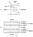
図4は、表示部20の一構成例を表すものであり、(A)は画素Pixを構成するサブ画素SPixの回路図の一例を示し、(B)は表示部20の断面構成を示す。
4A and 4B show an example of the configuration of the
画素Pixは、赤色(R)、緑色(G)、青色(B)にそれぞれ対応する3つのサブ画素SPixを有している。各サブ画素SPixは、図4(A)に示したように、TFT(Thin Film Transistor)素子Trと、液晶素子LCと、保持容量素子Csを備えている。TFT素子Trは、例えばMOS−FET(Metal Oxide Semiconductor-Field Effect Transistor)により構成されるものであり、ゲートがゲート線GCLに接続され、ソースがデータ線SGLに接続され、ドレインが液晶素子LCの一端と保持容量素子Csの一端に接続されている。液晶素子LCは、一端がTFT素子Trのドレインに接続され、他端は接地されている。保持容量素子Csは、一端がTFT素子Trのドレインに接続され、他端は保持容量線CSLに接続されている。ゲート線GCLはゲートドライバ52に接続され、データ線SGLはデータドライバ53に接続されている。
The pixel Pix has three subpixels SPix corresponding to red (R), green (G), and blue (B), respectively. Each sub-pixel SPix includes a TFT (Thin Film Transistor) element Tr, a liquid crystal element LC, and a storage capacitor element Cs as shown in FIG. The TFT element Tr is configured by, for example, a MOS-FET (Metal Oxide Semiconductor-Field Effect Transistor), the gate is connected to the gate line GCL, the source is connected to the data line SGL, and the drain is the liquid crystal element LC. One end and one end of the storage capacitor element Cs are connected. The liquid crystal element LC has one end connected to the drain of the TFT element Tr and the other end grounded. The storage capacitor element Cs has one end connected to the drain of the TFT element Tr and the other end connected to the storage capacitor line CSL. The gate line GCL is connected to the
表示部20は、図4(B)に示したように、駆動基板207と対向基板208との間に、液晶層203を封止したものである。駆動基板207は、透明基板201と、画素電極202と、偏光板206aとを有している。透明基板201は、例えばガラス等から構成されるものであり、TFT素子Trが形成されたものである。この透明基板201上には、サブ画素SPix毎に画素電極202が配設されている。そして、透明基板201の、画素電極202が配設された面とは反対の面には、偏光板206aが貼り付けられている。対向基板208は、透明基板205と、対向電極204と、偏光板206bとを有している。透明基板205は、例えばガラス等から構成されるものである。透明基板205の液晶層203側の面には、図示しないカラーフィルタやブラックマトリクスが形成され、さらにその上には、対向電極204が各サブ画素SPixに共通の電極として配設されている。透明基板205の、対向電極204が配設された面とは反対の面には、偏光板206bが貼り付けられている。偏光板206aおよび偏光板206bは、互いにクロスニコルまたはパラレルニコルとなるように貼り合わせられている。
As shown in FIG. 4B, the
図5は、表示部20におけるサブ画素SPixの配列を表すものである。図5において、“R”は赤色のサブ画素SPixを示し、“G”は緑色のサブ画素SPixを示し、“B”は青色のサブ画素SPixを示す。表示部20は、表示画面の垂直方向Yに長い長方形の形状を有する複数のサブ画素SPixがマトリックス状に配列している。具体的には、この例では、水平方向Xにおいて、赤色(R)、緑色(G)、青色(B)のサブ画素SPixが、この順で繰り返し配置されている。また、垂直方向Yにおいては、同じ色に係るサブ画素SPixが並んで配置されている。
FIG. 5 shows the arrangement of the sub-pixels SPix in the
(バリア部10)
図6は、バリア部10の一構成例を表すものであり、(A)はバリア部10の平面図を示し、(B)は(A)のバリア部10のVI−VI矢視方向の断面構成を示す。
(Barrier part 10)
6A and 6B show an example of the configuration of the
バリア部10は、いわゆるパララックスバリアであり、図6(A)に示したように、光を透過または遮断する複数の開閉部(液晶バリア)11,12を有している。開閉部11,12は、この例では、いわゆるステップバリアの形状を有している。この例では、開閉部11の幅W11と、開閉部12の幅W12とは、互いに異なっており、ここでは例えばW11>W12となっている。但し、開閉部11,12の幅の大小関係はこれに限定されず、W11<W12であってもよく、また、W11=W12であってもよい。
The
バリア部10は、図6(B)に示したように、駆動基板107と対向基板108との間に、液晶層103を封止したものである。駆動基板107は、透明基板101と、透明電極層102と、偏光板106aとを有している。透明基板101は、例えばガラス等から構成されるものであり、その上には、透明電極層102が形成されている。また、透明基板101の、透明電極層102が配設された面とは反対の面には、偏光板106aが貼り付けられている。対向基板108は、透明基板105と、透明電極層104と、偏光板106bとを有している。透明基板105は、例えばガラス等から構成されるものであり、その上には、透明電極層104が形成されている。透明基板105の、透明電極層104が配設された面とは反対の面には、偏光板106bが張り付けられている。偏光板106aおよび偏光板106bは、互いにクロスニコルまたはパラレルニコルとなるように貼り合わせられている。
As shown in FIG. 6B, the
透明電極層102は、複数の透明電極110,120を有している。また、透明電極層104は、複数の透明電極110,120に対応する位置にわたって、いわゆる共通電極として設けられるものである。透明電極110と、液晶層103および透明電極層104におけるその透明電極110に対応する部分とは、開閉部11を構成している。同様に、透明電極120と、液晶層103および透明電極層104におけるその透明電極120に対応する部分とは、開閉部12を構成している。このような構成により、バリア部10では、透明電極110または透明電極120に電圧を選択的に印加することにより、液晶層103がその電圧に応じた液晶配向になり、開閉部11,12毎の開閉動作を行うことができるようになっている。
The transparent electrode layer 102 has a plurality of
これらの開閉部11,12は、立体表示装置1が通常表示(2次元表示)および立体視表示のどちらを行うかにより、異なる動作を行う。具体的には、開閉部11は、後述するように、通常表示の際には開状態(透過状態)になり、立体視表示を行う際には、閉状態(遮断状態)となるものである。開閉部12は、後述するように、通常表示および立体視表示の両方において、開状態(透過状態)になるものである。
These open /
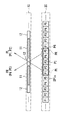
図7は、表示部20におけるサブ画素SPixと、バリア部10における開閉部12との位置関係を表すものである。なお、この図では、バリア部10における開閉部11の図示を省略している。すなわち、この図では、立体視表示の際に開状態となる開閉部12を図示しており、立体視表示の際に閉状態となる開閉部11の図示を省略している。開閉部12は、水平方向Xにおいて、隣接する5つのサブ画素SPix(サブ画素セットPG)に1つの割合で設けられている。そして、サブ画素セットPGは、その水平方向の中心が開閉部12に対応する位置になるように配置されている。
FIG. 7 illustrates the positional relationship between the sub-pixel SPix in the
図8は、立体視表示および通常表示(2次元表示)を行う場合のバリア部10の状態を、断面構造を用いて模式的に表すものであり、(A)は立体視表示を行う状態を示し、(B)は通常表示を行う状態を示す。図8において、斜線で示した開閉部11は、光が遮断されている状態を示している。
FIG. 8 schematically shows the state of the
立体視表示を行う場合には、表示駆動部50に映像信号S3Dが供給され、表示部20はそれに基づいて表示を行う。具体的には、図8(A)に示したように、バリア部10では、開閉部12が開状態(透過状態)になるとともに、開閉部11が閉状態(遮断状態)になる。そして、表示部20では、この開閉部12に対応する位置に配置された互いに隣接する5つのサブ画素SPix(サブ画素セットPG)が、後述するように、左眼画像FLに係る2つのサブ画素情報P1,P2(左眼画素情報PL)、補間画像FIに係る1つのサブ画素情報P3(補間画素情報PI)、および右眼画像FRに係る2つのサブ画素情報P4,P5(右眼画素情報PR)を表示する。これにより、観察者は、後述するように、左眼で左眼画素情報PLを観察するとともにと右眼で右眼画素情報PRを観察することにより、立体的な映像を見ることができる。また、表示部20は、後述するように、補間画素情報PIを表示することにより、観察者が感じるクロストークによる画質の劣化の低減を図っている。
When performing stereoscopic display, the video signal S3D is supplied to the
一方、通常表示(2次元表示)を行う場合には、表示駆動部50に映像信号S2Dが供給され、表示部20はそれに基づいて表示を行う。具体的には、図8(B)に示したように、バリア部10では、開閉部11,12がともに開状態(透過状態)になり、表示部20では、全てのサブ画素SPixが、1つの視点映像(2次元映像)を表示する。これにより、観察者は、表示部20に表示された通常の2次元映像をそのまま見ることができる。
On the other hand, when normal display (two-dimensional display) is performed, the video signal S2D is supplied to the
ここで、立体視表示を行うモードは、本開示における「第1の表示モード」の一具体例に対応する。サブ画素セットPGは、本開示における「基本画素セット」の一具体例に対応する。左眼画素情報PLを表示する2つのサブ画素の組、および右眼画素情報PRを表示する2つのサブ画素の組は、本開示における「第1の画素グループ」の一具体例に対応する。補間画素情報PIを表示するサブ画素は、本開示における「第2の画素グループ」の一具体例に対応する。開閉部12は、本開示における「第1系列の液晶バリア」の一具体例に対応し、開閉部11は、本開示における「第2系列の液晶バリア」の一具体例に対応する。
Here, the mode for performing the stereoscopic display corresponds to a specific example of “first display mode” in the present disclosure. The sub-pixel set PG corresponds to a specific example of “basic pixel set” in the present disclosure. The set of two subpixels that display the left eye pixel information PL and the set of two subpixels that display the right eye pixel information PR correspond to a specific example of “first pixel group” in the present disclosure. The sub-pixel displaying the interpolated pixel information PI corresponds to a specific example of “second pixel group” in the present disclosure. The opening / closing
[動作および作用]
続いて、本実施の形態の立体表示装置1の動作および作用について説明する。補間画像生成部41は、外部より供給される映像信号Sdispに基づいて補間画像処理を行い、映像信号Sdisp2を生成する。具体的には、補間画像生成部41は、立体表示装置1が立体視表示を行う場合において、映像信号Sdispに含まれる左眼画像FLおよび右眼画像FRに基づいて補間画像処理を行うことにより補間画像FIを生成し、これらの画像を含む映像信号Sdisp2を生成する。制御部42は、映像信号Sdisp2に基づいて、バックライト駆動部43、表示駆動部50、およびバリア駆動部44を制御する。バックライト駆動部43は、制御部42から供給されるバックライト制御信号に基づいてバックライト30を駆動する。バックライト30は、面発光した光を表示部20に対して射出する。表示駆動部50は、制御部42から供給される映像信号Sdisp3に基づいて表示部20を駆動する。表示部20は、バックライト30から射出した光を変調することにより表示を行う。具体的には、表示部20のサブ画素セットPGは、立体表示装置1が立体視表示を行う場合において、左眼画素情報PL、補間画素情報PI、および右眼画素情報PRを表示する。バリア駆動部44は、制御部42から供給されるバリア制御信号に基づいてバリア部10を制御する。バリア部10の開閉部11,12は、バリア駆動部44からの指示に基づいて開閉動作を行い、バックライト30から射出し表示部20を透過した光を透過または遮断する。
[Operation and Action]
Next, the operation and action of the
(立体視表示の詳細動作)
次に、立体視表示を行う場合の詳細動作を説明する。
(Detailed operation of stereoscopic display)
Next, a detailed operation when performing stereoscopic display will be described.
図9は、表示部20およびバリア部10における立体視表示の動作例を表すものである。立体視表示を行う場合には、バリア部10では、開閉部12が開状態(透過状態)になるとともに、開閉部11が閉状態(遮断状態)になる。そして、表示部20は、映像信号S3Dの画素情報を表示する。このとき、図9に示したように、開閉部12付近に配置された5つのサブ画素SPix(サブ画素セットPG)が、左眼画像FLに係る2つのサブ画素情報P1,P2(左眼画素情報PL)、補間画像FIに係る1つのサブ画素情報P3(補間画素情報PI)、および右眼画像FRに係る2つのサブ画素情報P4,P5(右眼画素情報PR)をそれぞれ表示する。表示部20の各サブ画素SPixから出た光は、開閉部12によりそれぞれ角度が制限されて出力される。これにより、観察者は、左眼で左眼画素情報PLを、右眼で右眼画素情報PRを見ることとなる。このようにして、観察者は、左眼および右眼で、左眼画像FLおよび右眼画像FRをそれぞれ観察することにより、表示映像を立体的な映像として感じることができる。
FIG. 9 illustrates an example of stereoscopic display operation in the
(左眼画像FLと右眼画像FRとの間のクロストーク)
図9に示したように、サブ画素セットPGは、左眼画素情報PLと右眼画素情報PRとの間に補間画素情報PIを表示する。これにより、立体表示装置1は、観察者が感じるクロストークによる画質の劣化を低減することができる。以下に、その詳細を説明する。
(Crosstalk between the left eye image FL and the right eye image FR)
As shown in FIG. 9, the sub-pixel set PG displays the interpolated pixel information PI between the left eye pixel information PL and the right eye pixel information PR. As a result, the
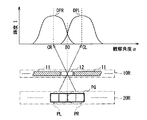
図10は、立体表示装置1のサブ画素セットPGから射出される光を模式的に表すものである。表示部20のサブ画素セットPGの5つのサブ画素SPixから射出された光は、液晶バリア部10の開状態にある開閉部12を透過してそれぞれ直進する。観察者は、これらの光の進行方向に対応した観察角度αからこれらの光を観察する。その際、各サブ画素SPixから射出した光は、それぞれの光の進行方向に対応した観察角度αにおいて、図10に示したような輝度分布を有する。具体的には、左眼画素情報PLの進行方向に対応する観察角度CLを中心に輝度分布DPLが生じ、補間画素情報PIの進行方向に対応する観察角度CIを中心に輝度分布DPIが生じ、右眼画素情報PRの進行方向に対応する観察角度CRを中心に輝度分布DPRが生じる。図10に示したように、輝度分布DPLに係る輝度Iと、輝度分布DPIに係る輝度Iとは、観察角度BLにおいて等しくなる。すなわち、観察角度BLは、輝度分布DPLと輝度分布DPIの境界に対応するものである。同様に、輝度分布DPIに係る輝度Iと、輝度分布DPRに係る輝度Iとは、観察角度BRにおいて等しくなる。すなわち、観察角度BRは、輝度分布DPIと輝度分布DPRの境界に対応するものである。
FIG. 10 schematically shows light emitted from the sub-pixel set PG of the
立体表示装置1は、観察者が表示画像を観察する際に、左眼の観察角度αが観察角度CL(輝度分布DPLの中心)付近になるとともに、右眼の観察角度αが観察角度CR(輝度分布DPRの中心)付近になるように設計される。その際、立体表示装置1では、2つのサブ画素情報P1,P2が左眼画素情報PLを構成し、2つのサブ画素情報P4,P5が右眼画素情報PRを構成するようにしたので、1つのサブ画素情報が左眼画素情報PLおよび右眼画素情報PRを構成する場合と比較して、輝度分布DPL,DPRの分布の幅を広くすることができる。これにより、観察者と立体表示装置1との相対的な位置関係が多少ずれても、輝度分布DPL,DPRの分布の幅が広いため、左眼が輝度分布DPLに係る光を観察し、右眼が輝度分布DPRに係る光を観察しやすくすることができ、所望の画像を観察することができる観察角度αの範囲を広げることができる。
In the
一方、観察者と立体表示装置1との相対的な位置関係が大きくずれた場合には、例えば、観察者は、左眼で輝度分布DPLに係る光に加えて輝度分布DPIに係る光をも観測するようになり、または、右眼で輝度分布DPRに係る光に加えて輝度分布DPIに係る光をも観測するようになる。すなわち、このような場合には、観察者は、本来観察すべき光に加え、観察すべきでない光をも観察するようになり、いわゆるクロストークが生じることとなる。
On the other hand, when the relative positional relationship between the observer and the
図11は、クロストークを表すものである。あるサブ画素SPixからの光を主に観察することができる観察角度範囲Rαの両端付近では、そのサブ画素SPixに隣接する他の視点画像に係るサブ画素SPixからの光も観測される。具体的には、例えば、観察角度α1では、所望のサブ画素SPixからの輝度I1の光に加え、隣接するサブ画素SPixからの輝度I2の光も観察される。このとき、クロストークCTは、次式で表される。
CT=I2/I1×100 ・・・(1)
すなわち、クロストークCTは、隣接するサブ画素SPixからの影響が大きいほど、その値が大きくなるものである。
FIG. 11 shows crosstalk. In the vicinity of both ends of the observation angle range Rα where light from a certain subpixel SPix can be mainly observed, light from the subpixel SPix related to another viewpoint image adjacent to the subpixel SPix is also observed. Specifically, for example, at the observation angle α1, in addition to the light having the luminance I1 from the desired subpixel SPix, the light having the luminance I2 from the adjacent subpixel SPix is also observed. At this time, the crosstalk CT is expressed by the following equation.
CT = I2 / I1 × 100 (1)
In other words, the value of the crosstalk CT increases as the influence from the adjacent subpixel SPix increases.
観察者と立体表示装置1との相対的な位置関係が大きくずれ、例えば、図10において、観察者が観察角度BLから観察する場合には、クロストークCTは100%になり、観察者は、互いに視差が異なる左眼画像FLおよび補間画像FIを2重像として観察することとなる。右眼についても全く同様であり、例えば、図10において、観察者が観察角度BRから観察する場合には、クロストークCTは100%になり、観察者は、互いに視差が異なる補間画像FIおよび右眼画像FRを2重像として観察することとなる。 For example, when the observer observes from the observation angle BL in FIG. 10, the crosstalk CT becomes 100%, and the observer The left eye image FL and the interpolated image FI having different parallax will be observed as a double image. The same applies to the right eye. For example, in FIG. 10, when the observer observes from the observation angle BR, the crosstalk CT is 100%, and the observer can see the interpolated image FI and right The eye image FR is observed as a double image.
図12は、クロストークが生じたときの表示画面の一例を表すものであり、(A)は、観察角度BLから観察した場合の表示画面を示し、(B)は、観察角度BRから観察した場合の表示画面を示す。観察者が観察角度BLから観察する場合には、図12(A)に示したような、左眼画像FLおよび補間画像FIの2重像を観察し、また、観察者が観察角度BRから観察する場合には、図12(B)に示したような、補間画像FIおよび右眼画像FRの2重像を観察する。このとき、補間画像FIは、左眼画像FLと右眼画像FRの中間視点に対応する画像であるため、左眼画像FLと補間画像FIとの間の視差は、左眼画像FLと右眼画像FRとの間の視差の約半分となり、同様に、補間画像FIと右眼画像FRとの間の視差は、左眼画像FLと右眼画像FRとの間の視差の約半分となる。これにより、立体表示装置1では、クロストークによる画質の劣化を低減することができる。
FIG. 12 shows an example of a display screen when crosstalk occurs, (A) shows the display screen when observed from the observation angle BL, and (B) is observed from the observation angle BR. The display screen is shown. When the observer observes from the observation angle BL, a double image of the left eye image FL and the interpolated image FI as shown in FIG. 12A is observed, and the observer observes from the observation angle BR. When doing so, a double image of the interpolated image FI and the right eye image FR as shown in FIG. 12B is observed. At this time, since the interpolation image FI is an image corresponding to an intermediate viewpoint between the left eye image FL and the right eye image FR, the parallax between the left eye image FL and the interpolation image FI is the left eye image FL and the right eye. Similarly, the parallax between the interpolated image FI and the right eye image FR is about half of the parallax between the left eye image FL and the right eye image FR. Thereby, in the
図13は、表示画像の視差と、観察者が感じるクロストークによる画質の劣化との関係を示す主観評価の結果を表すものである。図12において、横軸は、表示画像の視差から計算される飛出量を示している。すなわち、飛出量が大きいほど視差が大きいことを示している。縦軸は、観察者がどの位のクロストークCTまでなら許容できるかを表すクロストーク許容量を示している。図13に示したように、飛出量が低くなるにつれ、クロストーク許容量は増大する。すなわち、図13は、表示画像の視差が小さいほど、観察者はクロストークによる画質の劣化を感じにくくなり、大きなクロストークCTを許容できることを示している。 FIG. 13 shows the result of the subjective evaluation showing the relationship between the parallax of the display image and the deterioration of the image quality due to the crosstalk felt by the observer. In FIG. 12, the horizontal axis indicates the amount of projection calculated from the parallax of the display image. That is, the larger the pop-up amount, the greater the parallax. The vertical axis indicates the crosstalk tolerance that indicates how much crosstalk CT the observer can accept. As shown in FIG. 13, the allowable amount of crosstalk increases as the pop-out amount decreases. That is, FIG. 13 shows that as the parallax of the display image is smaller, the observer is less likely to perceive image quality degradation due to crosstalk, and a large crosstalk CT can be allowed.
立体表示装置1では、上述したように、左眼画像FLと右眼画像FRに加え、補間画像FIを表示したので、観察者と立体表示装置1との相対的な位置関係が大きくずれた場合でも、観察者が感じるクロストークによる画質の劣化を低減することができる。すなわち、立体表示装置1では、上述したように、表示部20のサブ画素セットPGが、左眼画素情報PLと右眼画素情報PRの間に補間画素情報PIを表示するようにしたので、左眼画素情報PLと右眼画素情報PRとを離れた位置に表示するため、左眼画像FLと右眼画像FRとの間にクロストークを生じにくくすることができる。また、クロストークが生じる左眼画像FLと補間画像FIとの間の視差、および補間画像FIと右眼画像FRとの間の視差が、左眼画像FLと右眼画像FRとの間の視差に比べて小さくなるようにしたので、図13に示したように、クロストーク許容量が増大し、観察者が感じるクロストークによる画質の劣化を低減することができる。
As described above, since the interpolated image FI is displayed in the
(隣接するサブ画素セットの間のクロストーク)
図14は、立体表示装置1の複数のサブ画素セットPGから射出される光を模式的に表すものである。サブ画素セットPGの5つのサブ画素SPixから射出された光が、開閉部12を透過して直進するのと同様に、そのサブ画素セットPGに隣接するサブ画素セットPGの各サブ画素SPixから射出された光も、その開閉部12を透過して直進し、図14に示したような輝度分布DPL2,DPR2が生じる。輝度分布DPL2は、観察角度BR2を境界として輝度分布DPRの隣に生じ、輝度分布DPR2は、観察角度BL2を境界として輝度分布DPLの隣に生じる。
(Crosstalk between adjacent sub-pixel sets)
FIG. 14 schematically illustrates light emitted from the plurality of subpixel sets PG of the
これらの輝度分布DPL2,DPR2は、観察者が観察すべきでない光である。すなわち、観察者は、上述したように、左眼で左眼映像FLに係る輝度分布DPLを主に観察し、右眼で右眼映像FRに係る輝度分布DPRを主に観察するのが望ましい。よって、観察者と立体表示装置1との相対的な位置関係が大きくずれ、例えば、観察者が、左眼で右眼画像FRに係る輝度分布DPR2を観察し、あるいは、右眼で左眼画像FLに係る輝度分布DPL2を観察する場合には、観察者は、画質が劣化したように感じることとなる。
These luminance distributions DPL2 and DPR2 are light that should not be observed by an observer. That is, as described above, it is desirable that the observer mainly observes the luminance distribution DPL related to the left eye image FL with the left eye and mainly observes the luminance distribution DPR related to the right eye image FR with the right eye. Therefore, the relative positional relationship between the observer and the
このような場合には、例えば、観察者の左眼の観察角度αが観察角度CLよりも内側になるとともに、右眼の観察角度がおよび右眼の観察角度αが観察角度CRよりも内側になるように設計することにより、画質の劣化を低減することができる。具体的には、図14に示したように、例えば、左眼の観察角度αが観察角度CL2(サブ画素情報P2に対応する輝度分布の中心)付近になるとともに、右眼の観察角度αが観察角度CR2(サブ画素情報P4に対応する輝度分布の中心)付近になるように設計することができる。 In such a case, for example, the observation angle α of the left eye of the observer is inside the observation angle CL, and the observation angle of the right eye and the observation angle α of the right eye are inside the observation angle CR. By designing so as to be, it is possible to reduce degradation of image quality. Specifically, as shown in FIG. 14, for example, the left-eye observation angle α is near the observation angle CL2 (the center of the luminance distribution corresponding to the sub-pixel information P2), and the right-eye observation angle α is It can be designed to be near the observation angle CR2 (the center of the luminance distribution corresponding to the sub-pixel information P4).
立体表示装置1では、2つのサブ画素情報P1,P2が左眼画素情報PLを構成し、2つのサブ画素情報P4,P5が右眼画素情報PRを構成するようにしたので、輝度分布DPL,DPRの分布の幅を広くすることができるため、観察者は画質が劣化したように感じるおそれを低減することができる。すなわち、観察者と立体表示装置1との相対的な位置関係が大きくずれ、左眼の観察角度αが、観察角度CL2から輝度分布DPR2の方向にずれた場合でも、観察角度CL2から観察角度BL2までの範囲ML内であれば、観察者は画質が劣化したように感じることはない。同様に、右眼の観察角度αが、観察角度CRから輝度分布DPL2の方向にずれた場合でも、観察角度CR2から観察角度BR2までの範囲MR内であれば、観察者は画質が劣化したように感じることはない。
In the
このように、立体表示装置1では、2つのサブ画素情報P1,P2が左眼画素情報PLを構成し、2つのサブ画素情報P4,P5が右眼画素情報PRを構成するようにしたので、1つのサブ画素情報が左眼画素情報PLおよび右眼画素情報PRを構成する場合と比較して、輝度分布DPL,DPRの分布の幅を広くすることができ、所望の画像を観察することができる観察角度αの範囲を広げることができる。
As described above, in the
次に、いくつかの比較例と対比して、本実施の形態の作用を説明する。 Next, the operation of the present embodiment will be described in comparison with some comparative examples.
(比較例1)
まず、比較例1に係る立体表示装置1Rについて説明する。本比較例は、補間画像FIを表示しないように構成したものである。
(Comparative Example 1)
First, the stereoscopic display device 1R according to Comparative Example 1 will be described. This comparative example is configured not to display the interpolation image FI.
図15は、比較例1に係る立体表示装置1Rにおけるサブ画素セットPGから射出される光を模式的に表すものである。この例では、サブ画素セットPGは、隣接する4つのサブ画素SPixにより構成されている。このサブ画素セットPGは、左眼画像FLに係る2つのサブ画素情報(左眼画素情報PL)、および右眼画像FRに係る2つのサブ画素情報(右眼画素情報PR)を表示する。すなわち、本比較例に係る立体表示装置1Rは、本実施の形態の場合とは異なり、補間画像FIに係るサブ画素情報を表示しないものである。なお、図示していないが、本比較例に係るバリア部の開閉部12は、水平方向Xにおいて、隣接する4つのサブ画素SPix(サブ画素セットPG)に1つの割合で設けられている。
FIG. 15 schematically illustrates light emitted from the sub-pixel set PG in the stereoscopic display device 1R according to the comparative example 1. In this example, the sub-pixel set PG includes four adjacent sub-pixels SPix. The sub pixel set PG displays two sub pixel information (left eye pixel information PL) related to the left eye image FL and two sub pixel information (right eye pixel information PR) related to the right eye image FR. That is, unlike the case of the present embodiment, the stereoscopic display device 1R according to this comparative example does not display the sub-pixel information related to the interpolation image FI. Although not shown, the opening /
各サブ画素SPixから射出した光は、それぞれの光の進行方向に対応した観察角度αにおいて、図15に示したような輝度分布を有する。具体的には、左眼画素情報PLの進行方向に対応する観察角度CLを中心に輝度分布DPLが生じ、右眼画素情報PRの進行方向に対応する観察角度CRを中心に輝度分布DPRが生じる。輝度分布DPLおよび輝度分布DPRは、観察角度B0を境界として隣り合って生じる。観察者と立体表示装置1との相対的な位置関係が大きくずれた場合には、例えば、観察者は、左眼で輝度分布DPLに係る光に加えて輝度分布DPRに係る光をも観測するようになり、または、右眼で輝度分布DPRに係る光に加えて輝度分布DPLに係る光をも観測するようになる。例えば、図15において、観察者が観察角度B0から観察する場合には、クロストークCTは100%になり、観察者は、互いに視差が異なる左眼画像FLおよび右眼画像FRを2重像として観察することとなる。
The light emitted from each sub-pixel SPix has a luminance distribution as shown in FIG. 15 at an observation angle α corresponding to the traveling direction of each light. Specifically, a luminance distribution DPL occurs around the observation angle CL corresponding to the traveling direction of the left eye pixel information PL, and a luminance distribution DPR occurs around the observation angle CR corresponding to the traveling direction of the right eye pixel information PR. . The luminance distribution DPL and the luminance distribution DPR are adjacent to each other with the observation angle B0 as a boundary. When the relative positional relationship between the observer and the
図16は、観察角度B0から観察した場合の表示画面を表すものである。このように、観察者が観察角度B0から観察した場合には、左眼画像FLおよび右眼画像FRが互いに大きい視差を有しているため、観察者は、互いに大きくずれた2重像を観察することとなる。このように、視差が大きい場合には、図13に示したように、クロストーク許容量が大幅に減少してしまうため、観察者は、クロストークによる画質の劣化を感じやすくなる。 FIG. 16 shows a display screen when observed from the observation angle B0. In this way, when the observer observes from the observation angle B0, the left eye image FL and the right eye image FR have a large parallax with each other, so the observer observes a double image greatly deviated from each other. Will be. As described above, when the parallax is large, as shown in FIG. 13, the allowable amount of crosstalk is greatly reduced, so that the observer easily perceives image quality degradation due to crosstalk.
一方、本実施の形態に係る立体表示装置1では、左眼画素情報PLと右眼画素情報PRの間に補間画素情報PIを表示するようにしたので、左眼画素情報PLと右眼画素情報PRとを離れた位置に表示することができ、大きな視差を有する左眼画像FLと右眼画像FRとの間にクロストークを生じにくくすることができる。また、クロストークが生じる左眼画像FLと補間画像FIとの間の視差、および補間画像FIと右眼画像FRとの間の視差が、左眼画像FLと右眼画像FRとの間の視差に比べて小さくなるようにしたので、図13に示したように、クロストーク許容量が増大するので、観察者が感じるクロストークによる画質の劣化を低減することができる。
On the other hand, in the
言い換えれば、本実施の形態に係る立体表示装置1は、補間画像FIを“緩衝画像”として用いることにより、クロストークによる画質の劣化を低減している。すなわち、本比較例に係る立体表示装置1Rでは、図15に示したように、観察者が観察する画像は、観察角度αが変化するにつれて、観察角度B0付近を境界として左眼画像FL(輝度分布DPL)と右眼画像FR(輝度分布DPR)との間で変化する。つまり、観察角度B0付近において、表示画像の視差が大きく変化する。一方、本実施の形態に係る立体表示装置1では、図10に示したように、観察者が観察する画像は、観察角度αが変化するにつれて、観察角度BL付近を境界として、観察する画像が左眼画像FL(輝度分布DPL)と補間画像FI(輝度分布DPI)との間で変化するとともに、観察角度BR付近を境界として、観察する画像が補間画像FI(輝度分布DPI)と右眼画像FR(輝度分布DPR)との間で変化する。つまり、本実施の形態では、表示画像の視差が、観察角度BL付近と観察角度BR付近とで半分ずつ2段階で変化する。このように、立体表示装置1では、大きな視差を有する左眼画像FLおよび右眼画像FRとともに、補間画像FIを表示するようにしたので、大きな視差の変化をやわらげることができ、観察者が感じるクロストークによる画質の劣化を低減することができる。
In other words, the
(比較例2)
次に、比較例2に係る立体表示装置1Sについて説明する。本比較例は、補間画像FIを表示しないように構成したものである。
(Comparative Example 2)
Next, the stereoscopic display device 1S according to the comparative example 2 will be described. This comparative example is configured not to display the interpolation image FI.
図17は、比較例2に係る立体表示装置1Sにおけるサブ画素セットPGから射出される光を模式的に表すものである。この例では、サブ画素セットPGは、隣接する3つのサブ画素SPixにより構成されている。このサブ画素セットPGは、左眼画像FLに係る1つのサブ画素情報(左眼画素情報PL)、補間画像FIに係るサブ画素情報(補間画素情報PI)、および右眼画像FRに係る1つのサブ画素情報(右眼画素情報PR)を表示する。すなわち、本比較例に係る立体表示装置1Sは、本実施の形態の場合とは異なり、左眼画素情報PLおよび右眼画素情報PRを、1つのサブ画素情報により構成するものである。なお、図示していないが、本比較例に係るバリア部の開閉部12は、水平方向Xにおいて、隣接する3つのサブ画素SPix(サブ画素セットPG)に1つの割合で設けられている。
FIG. 17 schematically illustrates light emitted from the sub-pixel set PG in the stereoscopic display device 1S according to the comparative example 2. In this example, the sub-pixel set PG is composed of three adjacent sub-pixels SPix. This subpixel set PG includes one subpixel information (left eye pixel information PL) related to the left eye image FL, one subpixel information (interpolated pixel information PI) related to the interpolation image FI, and one subpixel information related to the right eye image FR. The sub pixel information (right eye pixel information PR) is displayed. In other words, unlike the case of the present embodiment, the stereoscopic display device 1S according to the comparative example is configured to configure the left eye pixel information PL and the right eye pixel information PR with one subpixel information. Although not shown, the opening /
各サブ画素SPixから射出した光は、それぞれの光の進行方向に対応した観察角度αにおいて、図17に示したような輝度分布DPL,DPI,DPRを有する。また、そのサブ画素セットPGに隣接するサブ画素セットPGの各サブ画素SPixから射出された光も、同じ開閉部12を透過して直進し、図17に示したような輝度分布DPL2,DPR2が生じる。
The light emitted from each sub-pixel SPix has luminance distributions DPL, DPI, and DPR as shown in FIG. 17 at the observation angle α corresponding to the traveling direction of each light. Further, the light emitted from each sub-pixel SPix of the sub-pixel set PG adjacent to the sub-pixel set PG passes through the same opening /
本比較例に係る立体表示装置1Sでは、1つのサブ画素情報が左眼画素情報PLを構成し、1つのサブ画素情報が右眼画素情報PRを構成するようにしたので、輝度分布DPL,DPRの分布の幅が狭くなる。これにより、観察者と立体表示装置1Sとの相対的な位置関係が大きくずれ、左眼の観察角度αが、観察角度CLから輝度分布DPR2の方向にずれた場合、範囲MLが狭いので、観察者は、左眼で右眼画像FRを観察しやすくなってしまう。同様に、右眼の観察角度αが、観察角度CRから輝度分布DPL2の方向にずれた場合、範囲MRが狭いので、観察者は、右眼で左眼画像FLを観察しやすくなってしまう。 In the stereoscopic display device 1S according to this comparative example, one subpixel information constitutes the left eye pixel information PL, and one subpixel information constitutes the right eye pixel information PR. Therefore, the luminance distributions DPL, DPR The width of the distribution becomes narrower. As a result, when the relative positional relationship between the observer and the stereoscopic display device 1S greatly deviates, and the left-eye observation angle α deviates from the observation angle CL in the direction of the luminance distribution DPR2, the range ML is narrow. A person can easily observe the right eye image FR with the left eye. Similarly, when the observation angle α of the right eye is shifted from the observation angle CR in the direction of the luminance distribution DPL2, the range MR is narrow, so that the observer can easily observe the left eye image FL with the right eye.
一方、本実施の形態に係る立体表示装置1では、2つのサブ画素情報が左眼画素情報PLを構成し、2つのサブ画素情報が右眼画素情報PRを構成するようにしたので、輝度分布DPL,DPRの分布の幅を広くすることができ、所望の画像を観察することができる観察角度αの範囲を広げることができる。具体的には、本実施の形態に係る立体表示装置1(図14)では、比較例に係る立体表示装置1S(図17)と比べて、範囲ML,MRを約3倍に広げることができる。これにより、立体表示装置1では、左眼で右眼画像FRを観察し、右眼で左眼画像FLを観察するおそれを低減することができる。
On the other hand, in the
[効果]
以上のように本実施の形態では、各サブ画素セットにおいて、左眼画素情報と右眼画素情報の間に、補間画素情報を表示するようにしたので、左眼画像と補間画像との間の視差、および補間画像と右眼画像との間の視差を小さくすることができるため、観察者が感じるクロストークによる画質の劣化を低減することができる。
[effect]
As described above, in this embodiment, interpolation pixel information is displayed between left-eye pixel information and right-eye pixel information in each sub-pixel set, and therefore, between the left-eye image and the interpolation image. Since the parallax and the parallax between the interpolated image and the right eye image can be reduced, image quality degradation due to crosstalk felt by the observer can be reduced.
また、本実施の形態では、各サブ画素セットにおいて、左眼画素情報と右眼画素情報を離して表示したので、左眼画像と右眼画像との間にクロストークを生じにくくすることができる。 In the present embodiment, since the left-eye pixel information and the right-eye pixel information are displayed separately in each sub-pixel set, crosstalk is less likely to occur between the left-eye image and the right-eye image. .
また、本実施の形態では、各サブ画素セットにおいて、2つのサブ画素情報により左眼画素情報を構成するとともに、2つのサブ画素情報により右眼画素情報を構成したので、所望の画像を観察することができる観察角度の範囲を広げることができる。 In this embodiment, in each sub-pixel set, the left-eye pixel information is composed of two sub-pixel information and the right-eye pixel information is composed of two sub-pixel information, so that a desired image is observed. The range of observation angles that can be expanded.
[変形例1−1]
上記実施の形態では、2つのサブ画素情報により左眼画素情報を構成するとともに、2つのサブ画素情報により右眼画素情報を構成したが、これに限定されるものではなく、これに代えて、例えば、3つ以上のサブ画素情報により構成してもよい。図18は、3つのサブ画素情報により左眼画素情報および右眼画素情報をそれぞれ構成する場合の例を表すものである。本変形例に係るサブ画素セットPGは、隣接する7つのサブ画素SPixにより構成されている。サブ画素セットPGは、左眼画像FLに係る3つのサブ画素情報(左眼画素情報PL)、補間画像FIに係る1つのサブ画素情報(補間画素情報PI)、右眼画像FRに係る3つのサブ画素情報(右眼画素情報PR)を表示する。なお、図示していないが、本変形例に係るバリア部の開閉部12は、水平方向Xにおいて、隣接する7つのサブ画素SPix(サブ画素セットPG)に1つの割合で設けられている。これにより、輝度分布DPL,DPRの分布の幅を広くすることができ、所望の画像を観察することができる観察角度αの範囲をさらに広げることができる。
[Modification 1-1]
In the above embodiment, the left-eye pixel information is configured by the two sub-pixel information and the right-eye pixel information is configured by the two sub-pixel information. However, the present invention is not limited to this. For example, it may be constituted by three or more subpixel information. FIG. 18 shows an example in which left-eye pixel information and right-eye pixel information are respectively configured by three sub-pixel information. The sub-pixel set PG according to the present modification is composed of seven adjacent sub-pixels SPix. The sub pixel set PG includes three sub pixel information (left eye pixel information PL) related to the left eye image FL, one sub pixel information (interpolated pixel information PI) related to the interpolation image FI, and three sub pixels information related to the right eye image FR. The sub pixel information (right eye pixel information PR) is displayed. Although not shown, the opening /
[変形例1−2]
上記実施の形態では、補間画像生成部41が1つの補間画像FIを生成したが、これに限定されるものではなく、これに代えて、補間画像生成部が互いに視差が異なる2以上の補間画像を生成してもよい。以下に、補間画像生成部が2つの補間画像FIL,FIRを生成し、サブ画素セットPGが、これらの2つの補間画像FIL,FIRに対応する2つの補間画素情報PIL,PIRを表示する場合の例を詳細に説明する。
[Modification 1-2]
In the above embodiment, the interpolation
図19は、本変形例に係る立体表示装置1Cの補間画像生成部41Cが取り扱う画像の一例を模式的に表すものであり、(A)は左眼画像FLを示し、(B)は右眼画像FRを示し、(C)は補間画像FILを示し、(D)は補間画像FIRを示す。補間画像生成部41Cは、左眼画像FLおよび右眼画像FRに基づいて、それらの視点間に位置する第1の視点に係る補間画像FIL(図19(C))および第2の視点に係る補間画像FIR(図19(D))を、補間画像処理により生成する。この例では、左眼画像FLと補間画像FILとの間の視差と、補間画像FILと補間画像FIRとの間の視差と、補間画像FIRと右眼画像FRとの間の視差とは、互いに等しくなっている。すなわち、補間画像生成部41Cは、左眼画像FLおよび右眼画像FRの視点間を3等分することにより、2つの補間画像FIL,FIRを生成する。 FIG. 19 schematically illustrates an example of an image handled by the interpolation image generation unit 41C of the stereoscopic display device 1C according to the present modification, where (A) shows the left eye image FL and (B) shows the right eye. An image FR is shown, (C) shows an interpolated image FIL, and (D) shows an interpolated image FIR. Based on the left eye image FL and the right eye image FR, the interpolated image generation unit 41C relates to the interpolated image FIL (FIG. 19C) related to the first viewpoint located between these viewpoints and the second viewpoint. An interpolation image FIR (FIG. 19D) is generated by interpolation image processing. In this example, the parallax between the left eye image FL and the interpolated image FIL, the parallax between the interpolated image FIL and the interpolated image FIR, and the parallax between the interpolated image FIR and the right eye image FR are mutually Are equal. That is, the interpolated image generation unit 41C generates two interpolated images FIL and FIR by equally dividing the viewpoints of the left eye image FL and the right eye image FR into three equal parts.
図20は、本変形例に係る立体表示装置1Cにおけるサブ画素セットPGから射出される光を模式的に表すものである。この例では、サブ画素セットPGは、隣接する8つのサブ画素SPixにより構成されている。このサブ画素セットPGは、左眼画像FLに係る3つのサブ画素情報(左眼画素情報PL)、補間画像FILに係る1つのサブ画素情報(補間画素情報PIL)、補間画像FIRに係る1つのサブ画素情報(補間画素情報PIR)、および右眼画像FRに係る3つのサブ画素情報(右眼画素情報PR)を表示する。なお、図示していないが、本変形例に係るバリア部の開閉部12は、水平方向Xにおいて、隣接する8つのサブ画素SPix(サブ画素セットPG)に1つの割合で設けられている。
FIG. 20 schematically illustrates light emitted from the sub-pixel set PG in the stereoscopic display device 1C according to this modification. In this example, the sub-pixel set PG includes eight adjacent sub-pixels SPix. The sub-pixel set PG includes three sub-pixel information (left-eye pixel information PL) related to the left eye image FL, one sub-pixel information (interpolated pixel information PIL) related to the interpolated image FIL, and one sub-pixel information related to the interpolated image FIR. The sub pixel information (interpolated pixel information PIR) and the three sub pixel information (right eye pixel information PR) related to the right eye image FR are displayed. Although not shown, the opening /
各サブ画素SPixから射出した光は、それぞれの光の進行方向に対応した観察角度αにおいて、図20に示したような輝度分布を有する。具体的には、左眼画素情報PLの進行方向に対応する観察角度CLを中心に輝度分布DPLが生じ、補間画素情報PILの進行方向に対応する観察角度を中心に輝度DPILが生じ、補間画素情報PIRの進行方向に対応する観察角度を中心に輝度DPIRが生じ、右眼画素情報PRの進行方向に対応する観察角度CRを中心に輝度分布DPRが生じる。輝度分布DPLと輝度分布DPILは、観察角度BLを境界として隣り合って生じ、輝度分布DPILと輝度分布DPIRは、観察角度BCを境界として隣り合って生じ、輝度分布DPIRと輝度分布DPRは、観察角度BRを境界として隣り合って生じる。 The light emitted from each sub-pixel SPix has a luminance distribution as shown in FIG. 20 at the observation angle α corresponding to the traveling direction of each light. Specifically, the luminance distribution DPL is generated around the observation angle CL corresponding to the traveling direction of the left eye pixel information PL, and the luminance DPIL is generated around the observation angle corresponding to the traveling direction of the interpolation pixel information PIL. A luminance DPIR is generated around the observation angle corresponding to the traveling direction of the information PIR, and a luminance distribution DPR is generated around the observation angle CR corresponding to the traveling direction of the right-eye pixel information PR. The luminance distribution DPL and the luminance distribution DPIL are adjacent to each other with the observation angle BL as a boundary, the luminance distribution DPIL and the luminance distribution DPIR are adjacent to each other with the observation angle BC as a boundary, and the luminance distribution DPIR and the luminance distribution DPR are It occurs adjacent to the angle BR as a boundary.
図21は、クロストークが生じたときの表示画面の一例を表すものであり、(A)は観察角度BLから観察した場合の表示画面を示し、(B)は観察角度BCから観察した場合の表示画面を示し、(C)は観察角度BRから観察した場合の表示画面を示す。観察者が観察角度BLから観察する場合には、図21(A)に示したような、左眼画像FLおよび補間画像FILの2重像を観察し、観察者が観察角度BCから観察する場合には、図21(B)に示したような、補間画像FILおよび補間画像FIRの2重像を観察し、観察者が観察角度BRから観察する場合には、図21(C)に示したような、補間画像FIRおよび右眼画像FRの2重像を観察する。このとき、左眼画像FLと補間画像FILとの間の視差、補間画像FILと補間画像FIRとの間の視差、および補間画像FIRと右眼画像FRとの間の視差は、ともに、左眼画像FLと右眼画像FRとの間の視差の約1/3となる。これにより、立体表示装置1では、クロストークによる画質の劣化を低減することができる。
FIG. 21 shows an example of a display screen when crosstalk occurs. (A) shows a display screen when observed from the observation angle BL, and (B) shows a case when observed from the observation angle BC. A display screen is shown, (C) shows a display screen when observed from the observation angle BR. When the observer observes from the observation angle BL, a double image of the left eye image FL and the interpolated image FIL as shown in FIG. 21A is observed, and the observer observes from the observation angle BC. FIG. 21C shows a case where a double image of the interpolated image FIL and the interpolated image FIR as shown in FIG. 21B is observed and the observer observes from the observation angle BR. A double image of the interpolated image FIR and the right eye image FR is observed. At this time, the parallax between the left eye image FL and the interpolated image FIL, the parallax between the interpolated image FIL and the interpolated image FIR, and the parallax between the interpolated image FIR and the right eye image FR are all left eye. This is about 1/3 of the parallax between the image FL and the right eye image FR. Thereby, in the
[変形例1−3]
上記実施の形態では、立体表示装置1は、3つの視点画像(左眼画像FL、補間画像FI、および右眼画像FR)を表示するものとしたが、これに限定されるものではなく、これに代えて、4つ以上の視点画像を表示してもよい。図22は、7つの視点画像を表示する場合の例を表すものである。本変形例に係る立体表示装置1Dでは、補間画像生成部41Dが、4つの視点画像FV1,FV2,FV3,FV4(図示せず)を含む映像信号Sdispに基づいて、補間画像生成処理を行う。具体的には、補間画像生成部41Dは、視点画像FV1,FV2に基づいて補間画像FI1(図示せず)を生成し、視点画像FV2,FV3に基づいて補間画像FI2(図示せず)を生成し、視点画像FV3,FV4に基づいて補間画像FI3(図示せず)を生成する。そして、隣接する11個のサブ画素SPixから構成されるサブ画素セットPGのそれぞれは、視点画像FV1に係る視点画素情報PV1、補間画像FI1に係る補間画素情報PI1、視点画像FV2に係る視点画素情報PV2、補間画像FI2に係る補間画素情報PI2、視点画像FV3に係る視点画素情報PV3、補間画像FI3に係る補間画素情報PI3、および視点画像FV4に係る視点画素情報PV4を表示する。その際、各サブ画素セットPGは、視点画素情報PV1と視点画素情報PV2との間に補間画素情報PI1を表示し、視点画素情報PV2と視点画素情報PV3との間に補間画素情報PI2を表示し、視点画素情報PV3と視点画素情報PV4との間に補間画素情報PI3を表示する。なお、図示していないが、本変形例に係るバリア部の開閉部12は、水平方向Xにおいて、隣接する11個のサブ画素SPix(サブ画素セットPG)に1つの割合で設けられている。
[Modification 1-3]
In the above embodiment, the
[変形例1−4]
上記実施の形態では、サブ画素SPixを単位としてセット(サブ画素セットPG)を構成したが、これに限定されるものではなく、これに代えて、例えば画素Pixを単位としてセットを構成してもよい。この場合には、例えば、図9において、各画素セットPGは、5つの画素Pixにより構成され、5つの画素Pixの画素情報P1〜P5を表示するものである。
[Modification 1-4]
In the above embodiment, the set (sub-pixel set PG) is configured with the sub-pixel SPix as a unit. However, the present invention is not limited to this. For example, the set may be configured with the pixel Pix as a unit. Good. In this case, for example, in FIG. 9, each pixel set PG includes five pixels Pix, and displays pixel information P1 to P5 of the five pixels Pix.
[変形例1−5]
上記実施の形態では、左眼画像FLおよび右眼画像FRに基づいて補間画像FIを生成する補間画像生成部41を設けたが、これに限定されるものではなく、これに代えて、補間画像生成部41を設けなくてもよい。この場合には、例えば左眼画像FL、補間画像FI、右眼画像FRに対応する3視点の視点画像を含む映像信号が、外部から制御部42に直接供給される。
[Modification 1-5]
In the above-described embodiment, the interpolation
<2.第2の実施の形態>
次に、第2の実施の形態に係る立体表示装置2について説明する。本実施の形態は、サブ画素セットが、左眼画素情報PLと右眼画素情報PRとの間に補間画素情報PIを表示するとともに、左眼画素情報PLおよび右眼画素情報PRの外側にも他の画素情報を表示するものである。なお、上記第1の実施の形態に係る立体表示装置1と実質的に同一の構成部分には同一の符号を付し、適宜説明を省略する。
<2. Second Embodiment>
Next, the
図23は、本実施の形態に係る立体表示装置2の一構成例を表すものである。立体表示装置2は、画像生成部61を備えている。
FIG. 23 illustrates a configuration example of the
画像生成部61は、外部より供給される映像信号Sdispに基づいて画像処理を行い、映像信号Sdisp2を生成するものである。具体的には、画像生成部61は、立体表示装置1が立体視表示を行う場合において、映像信号Sdispに含まれる左眼画像FLおよび右眼画像FRに基づいて、補間画像処理により補間画像FIを生成するとともに、外挿画像処理により外挿画像FEL,FERを生成する機能を有している。
The
図24は、画像生成部61が取り扱う画像の一例を模式的に表すものであり、(A)は左眼画像FLを示し、(B)は右眼画像FRを示し、(C)は外挿画像FELを示し、(D)は外挿画像FERを示す。画像生成部61は、左眼画像FLおよび右眼画像FRに基づいて、上記第1の実施の形態と同様に補間画像FI(図2(C))を生成するとともに、左眼画像FLよりさらに左側の視点に係る視点画像である外挿画像FEL(図24(C))、および右眼画像FRよりさらに右側の視点に係る視点画像である外挿画像FER(図24(D))を生成する。
FIG. 24 schematically illustrates an example of an image handled by the
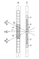
図25は、立体表示装置2のサブ画素セットPGから射出される光を模式的に表すものである。立体表示装置2のサブ画素セットPGは、隣接する7つのサブ画素SPixにより構成されている。このサブ画素セットPGは、外挿画像FELに係る1つのサブ画素情報(外挿画素情報PEL)、左眼画像FLに係る2つのサブ画素情報(左眼画素情報PL)、補間画像FIに係る1つのサブ画素情報(補間画素情報PI)、右眼画像FRに係る2つのサブ画素情報(右眼画素情報PR)、および外挿画像FERに係る1つのサブ画素情報(外挿画素情報PER)を表示する。なお、図示していないが、本実施の形態に係るバリア部の開閉部12は、水平方向Xにおいて、隣接する7つのサブ画素SPix(サブ画素セットPG)に1つの割合で設けられている。
FIG. 25 schematically illustrates light emitted from the sub-pixel set PG of the
各サブ画素SPixから射出した光は、それぞれの光の進行方向に対応した観察角度αにおいて、図25に示したような輝度分布を有する。具体的には、外挿画素情報PELの進行方向に対応する観察角度CELを中心に輝度分布DPELが生じ、左眼画素情報PLの進行方向に対応する観察角度CLを中心に輝度分布DPLが生じ、補間画素情報PIの進行方向に対応する観察角度CIを中心に輝度DPIが生じ、右眼画素情報PRの進行方向に対応する観察角度CRを中心に輝度分布DPRが生じ、外挿画素情報PERの進行方向に対応する観察角度CERを中心に輝度分布DPERが生じる。 The light emitted from each sub-pixel SPix has a luminance distribution as shown in FIG. 25 at an observation angle α corresponding to the traveling direction of each light. Specifically, a luminance distribution DPEL occurs around the observation angle CEL corresponding to the traveling direction of the extrapolated pixel information PEL, and a luminance distribution DPL occurs around the observation angle CL corresponding to the traveling direction of the left eye pixel information PL. , The luminance DPI occurs around the observation angle CI corresponding to the traveling direction of the interpolated pixel information PI, the luminance distribution DPR occurs around the observation angle CR corresponding to the traveling direction of the right-eye pixel information PR, and extrapolated pixel information PER. A luminance distribution DPER is generated around the observation angle CER corresponding to the traveling direction of.
立体表示装置2では、各サブ画素セットPGにおいて、左眼画素情報PLおよび右眼画素情報PRの外側に外挿画素情報PEL,PERを表示するようにしたので、範囲MLおよび範囲MRを広くすることができるので、観察者は画質が劣化したように感じるおそれを低減することができる。すなわち、観察者と立体表示装置1との相対的な位置関係が大きくずれ、左眼の観察角度αが、観察角度CLから外側にずれた場合でも、範囲ML内であれば、観察者は画質が劣化したように感じることはない。同様に、右眼の観察角度αが、観察角度CRから外側にずれた場合でも、範囲MR内であれば、観察者は画質が劣化したように感じることはない。
In the
また、立体表示装置2では、各サブ画素セットPGにおいて、左眼画素情報PLおよび右眼画素情報PRの外側に外挿画素情報PEL,PERを表示するようにしたので、観察者は、より自然な立体視表示を観察できるようになる。すなわち、観察者と立体表示装置1との相対的な位置関係が大きくずれ、観察者が、左眼で輝度分布DPELを観察する場合には、左眼画像FLよりもさらに左の視点に係る外挿画像FELを観察することとなり、また、観察者が、右眼で輝度分布DPERを観察する場合には、右眼画像FRよりもさらに右の視点に係る外挿画像FERを観察することとなる。これにより、観察者は、より多視点の立体視表示を観察することができる。
Further, in the
以上のように本実施の形態では、各サブ画素セットにおいて、左眼画素情報および右眼画素情報の外側に外挿画素情報を表示するようにしたので、所望の画像を観察することができる観察角度の範囲を広げることができるとともに、より自然な立体視表示を観察できる。その他の効果は、上記第1の実施の形態の場合と同様である。 As described above, in the present embodiment, extrapolated pixel information is displayed outside the left-eye pixel information and the right-eye pixel information in each sub-pixel set, so that a desired image can be observed. The range of angles can be expanded and more natural stereoscopic display can be observed. Other effects are the same as in the case of the first embodiment.
[変形例2−1]
例えば、本実施の形態に、上記第1の実施の形態の各変形例を適用してもよい。
[Modification 2-1]
For example, each modification of the first embodiment may be applied to the present embodiment.
<3.適用例>
次に、上記実施の形態および変形例で説明した立体表示装置の適用例について説明する。
<3. Application example>
Next, application examples of the stereoscopic display device described in the above embodiment and modifications will be described.
図26は、上記実施の形態等の立体表示装置が適用されるテレビジョン装置の外観を表すものである。このテレビジョン装置は、例えば、フロントパネル511およびフィルターガラス512を含む映像表示画面部510を有しており、この映像表示画面部510は、上記実施の形態等に係る立体表示装置により構成されている。 FIG. 26 illustrates an appearance of a television device to which the stereoscopic display device according to the above-described embodiment or the like is applied. This television apparatus has, for example, a video display screen unit 510 including a front panel 511 and a filter glass 512. The video display screen unit 510 is configured by the stereoscopic display device according to the above-described embodiment and the like. Yes.
上記実施の形態等の立体表示装置は、このようなテレビジョン装置の他、デジタルカメラ、ノート型パーソナルコンピュータ、携帯電話等の携帯端末装置、携帯型ゲーム機、あるいはビデオカメラなどのあらゆる分野の電子機器に適用することが可能である。言い換えると、上記実施の形態等の立体表示装置は、映像を表示するあらゆる分野の電子機器に適用することが可能である。 The stereoscopic display device according to the above-described embodiment is an electronic device in various fields such as a digital camera, a notebook personal computer, a portable terminal device such as a mobile phone, a portable game machine, or a video camera in addition to such a television device. It can be applied to equipment. In other words, the stereoscopic display device according to the above-described embodiment can be applied to electronic devices in all fields that display video.
以上、いくつかの実施の形態および変形例、ならびに電子機器への適用例を挙げて本技術を説明したが、本技術はこれらの実施の形態等には限定されず、種々の変形が可能である。 The present technology has been described above with some embodiments and modifications, and application examples to electronic devices. However, the present technology is not limited to these embodiments and the like, and various modifications are possible. is there.
例えば、上記各実施の形態等では、バリア部10の各開閉部11,12は、ステップバリアの形状を有するとしたが、これに限定されるものではなく、これに代えて、例えば、図27に示したように、斜め方向に延伸するように構成してもよいし、図28に示したように、垂直方向Yに延伸するように構成してもよい。図28に示したように構成した場合には、例えば、各サブ画素SPixは、水平方向Xに長い長方形の形状を有するように構成してもよい。
For example, in each of the above-described embodiments and the like, the open /
また、例えば、上記各実施の形態等では、立体視表示を行う場合において、開閉部12を常に開状態にしたが、これに限定されるものではなく、これに代えて、例えば、開閉部12を複数のグループにグループ分けして、グループ間で時分割的に開閉駆動するようにしてもよい。例えば、開閉部12を2つのグループにグループ分けし、グループ間で交互に開閉動作させた場合には、立体表示装置の解像度を2倍に高めることができる。
Further, for example, in each of the above-described embodiments and the like, the opening /
また、例えば、上記各実施の形態等では、バックライト30、表示部20、バリア部10は、この順に配置したが、これに限定されるものではなく、これに代えて、図29に示したように、バックライト30、バリア部10、表示部20の順に配置してもよい。図30は、本変形例に係る表示部20およびバリア部10の動作例を表すものである。本変形例では、バックライト30から射出した光は、まずバリア部10に入射する。そして、その光のうち、開閉部12を透過した光が表示部20において変調されることにより、左眼画素情報PL(左眼画像FL)、補間画素情報PI(補間画像FI)、および右眼画素情報PR(右眼画素FR)を表示する。
Further, for example, in each of the above-described embodiments, the
また、例えば、上記各実施の形態等では、表示部20およびバックライト30を用いたが、これに限定されるものではなく、これに代えて、例えば、EL(Electro Luminescence)などの表示部を用いてもよい。
In addition, for example, in each of the above-described embodiments, the
また、例えば、上記各実施の形態等では、光の透過率を変化させることができる開閉部11,12を用いてバリア部10を構成したが、これに代えて、例えば、開閉部11に対応する部分の光を遮断し、開閉部12に対応する部分が開口して光を透過する、固定のバリアを用いてバリア部を構成してもよい。この場合でも、立体視表示の際には、上記実施の形態の場合(図9等)と同様に表示を行うことができる。また、通常表示(2次元表示)の際には、例えば、開口部付近に配置された5つのサブ画素SPix(サブ画素セットPG)が、一つの画素情報を表示することにより、2次元画像を表示することができる。
Further, for example, in each of the above-described embodiments, the
また、例えば、上記各実施の形態等では、パララックスバリア方式の立体表示装置を構成したが、これに限定されるものではなく、これに代えて、例えばレンチキュラーレンズ方式の立体表示装置を構成してもよい。以下にその詳細を説明する。 Further, for example, in each of the above-described embodiments and the like, a parallax barrier type stereoscopic display device is configured, but the present invention is not limited to this, and instead, for example, a lenticular lens type stereoscopic display device is configured. May be. Details will be described below.
図31は、レンチキュラーレンズ方式の立体表示装置9における立体視表示の動作例を表すものである。立体表示装置9は、バックライト30から射出し表示部20を透過した光を屈折させる複数のレンズ99を有するレンズ部90を備えている。立体視表示を行う場合には、表示部20では、各レンズ99に対応する部分に配置された5つのサブ画素SPix(サブ画素セットPG)が、左眼画素情報PL(左眼画像FL)、補間画素情報PI(補間画像FI)、および右眼画素情報PR(右眼画素FR)をそれぞれ表示する。そして、表示部20の各サブ画素SPixから出た光は、レンズ99により屈折され、それぞれの方向に向かって出力される。
FIG. 31 shows an example of stereoscopic display operation in the lenticular lens type stereoscopic display device 9. The stereoscopic display device 9 includes a lens unit 90 including a plurality of
なお、レンズ99は、成形され、屈折率が固定されたレンズであってもよいし、例えば、液晶レンズや液体レンズのように、屈折率などの特性を可変に構成したものであってもよい。
The
なお、本技術は以下のような構成とすることができる。 In addition, this technique can be set as the following structures.
(1)表示部と、
前記表示部からの光線または前記表示部に向かう光線に対して制御を行う光線制御部と
を備え、
2以上の第1の視点画像と、前記第1の視点画像のそれぞれの画素数よりも少ない画素数の1または複数の第2の視点画像とを含む複数の視点画像が前記表示部に表示される第1の表示モードを有する
表示装置。
(1) a display unit;
A light control unit that controls the light from the display unit or the light toward the display unit, and
A plurality of viewpoint images including two or more first viewpoint images and one or a plurality of second viewpoint images having a smaller number of pixels than the number of pixels of each of the first viewpoint images are displayed on the display unit. A display device having the first display mode.
(2)前記第1の視点画像のそれぞれが、複数画素からなる第1の画素グループを用いて表示され、
前記第2の視点画像のそれぞれが、前記第1の画素グループの画素数よりも少ない画素からなる第2の画素グループを用いて表示され、
前記2以上の第1の視点画像の表示に用いられる2以上の前記第1の画素グループと、前記1または複数の第2の視点画像の表示に用いられる1または複数の前記第2の画素グループとが、1つの基本画素セットを構成する
前記(1)に記載の表示装置。
(2) Each of the first viewpoint images is displayed using a first pixel group consisting of a plurality of pixels,
Each of the second viewpoint images is displayed using a second pixel group comprising fewer pixels than the number of pixels of the first pixel group;
Two or more first pixel groups used for displaying the two or more first viewpoint images, and one or more second pixel groups used for displaying the one or more second viewpoint images. And constitutes one basic pixel set. The display device according to (1).
(3)前記基本画素セット内において、前記第1の画素グループ同士の間に前記第2の画素グループが内挿されている
前記(2)に記載の表示装置。
(3) The display device according to (2), wherein in the basic pixel set, the second pixel group is inserted between the first pixel groups.
(4)前記第2の画素グループの各画素は、前記第1の画素グループの画素から補間処理により生成された補間画素である
前記(3)に記載の表示装置。
(4) The display device according to (3), wherein each pixel of the second pixel group is an interpolation pixel generated by interpolation processing from a pixel of the first pixel group.
(5)前記基本画素セット内において、最外端位置に前記第2の画素グループの画素が外挿されている
前記(2)に記載の表示装置。
(5) The display device according to (2), wherein a pixel of the second pixel group is extrapolated at an outermost end position in the basic pixel set.
(6)外挿された前記画素は、最外端位置を視点位置とする視点画像の画素である
前記(4)に記載の表示装置。
(6) The display device according to (4), wherein the extrapolated pixels are pixels of a viewpoint image whose outermost end position is a viewpoint position.
(7)前記基本画素セット内において、前記第1の画素グループ同士の間に前記第2の画素グループに属する内挿用画素グループが内挿され、最外端位置に前記第2の画素グループに属する外挿用画素グループが外挿されている
前記(2)に記載の表示装置。
(7) In the basic pixel set, an interpolation pixel group belonging to the second pixel group is inserted between the first pixel groups, and the second pixel group is located at the outermost end position. The display device according to (2), wherein an extrapolation pixel group to which the extrapolation belongs is extrapolated.
(8)前記2以上の第1の視点画像は、左眼画像および右眼画像であり、
前記第2の視点画像は、前記左眼画像および前記右眼画像の1または複数の補間画像である
前記(4)に記載の表示装置。
(8) The two or more first viewpoint images are a left eye image and a right eye image,
The display device according to (4), wherein the second viewpoint image is one or a plurality of interpolation images of the left eye image and the right eye image.
(9)前記光線制御部は、前記表示部に表示された各視点画像からの光線または各視点画像に向かう光線を、それぞれ対応する角度方向に規制するように動作する
前記(1)から(8)のいずれかに記載の表示装置。
(9) The light ray control unit operates to restrict light rays from each viewpoint image displayed on the display unit or light rays directed to each viewpoint image in corresponding angular directions, respectively (1) to (8 ).
(10)単一の視点画像が前記表示部に表示され、かつ、前記光線制御部が、前記単一の視点画像からの光線または前記単一の視点画像に向かう光線をそのまま透過させるように動作する第2の表示モードをさらに有する
前記(1)から(9)のいずれかに記載の表示装置。
(10) A single viewpoint image is displayed on the display unit, and the light ray control unit operates so as to transmit light rays from the single viewpoint image or light rays toward the single viewpoint image as they are. The display device according to any one of (1) to (9), further including a second display mode.
(11)前記光線制御部は、光を透過または遮断するバリア部であり、
前記バリア部は、開状態と閉状態とを切り換え可能な、複数の第1系列の液晶バリアおよび複数の第2系列の液晶バリアを有する
前記(2)から(9)のいずれかに記載の表示装置。
(11) The light beam control unit is a barrier unit that transmits or blocks light,
The display according to any one of (2) to (9), wherein the barrier section includes a plurality of first-series liquid crystal barriers and a plurality of second-series liquid crystal barriers capable of switching between an open state and a closed state. apparatus.
(12)前記複数の第1系列の液晶バリアが透過状態になるとともに、前記複数の第2系列の液晶バリアが遮断状態になり、
前記基本画素セットは、前記複数の第1系列の液晶バリアに対応する位置に設けられている
前記(11)に記載の表示装置。
(12) The plurality of first series liquid crystal barriers are in a transmissive state, and the plurality of second series liquid crystal barriers are in a blocked state,
The display device according to (11), wherein the basic pixel set is provided at a position corresponding to the plurality of first-series liquid crystal barriers.
(13)前記光線制御部は、光を透過または遮断するバリア部であり、
前記バリア部は、複数の固定された開口部を有する
前記(1)から(10)のいずれかに記載の表示装置。
(13) The light beam control unit is a barrier unit that transmits or blocks light,
The display device according to any one of (1) to (10), wherein the barrier section includes a plurality of fixed openings.
(14)前記光線制御部は、屈折率を切り換え可能な、複数の可変レンズを有する
前記(1)から(10)のいずれかに記載の表示装置。
(14) The display device according to any one of (1) to (10), wherein the light beam control unit includes a plurality of variable lenses capable of switching a refractive index.
(15)前記光線制御部は、複数の固定されたレンズを有する
前記(1)から(10)のいずれかに記載の表示装置。
(15) The display device according to any one of (1) to (10), wherein the light beam control unit includes a plurality of fixed lenses.
(16)バックライトをさらに備え、
前記表示部は液晶表示部であり、
前記液晶表示部は、前記バックライトと前記光線制御部との間に配置されている
前記(1)から(15)のいずれかに記載の表示装置。
(16) A backlight is further provided,
The display unit is a liquid crystal display unit;
The display device according to any one of (1) to (15), wherein the liquid crystal display unit is disposed between the backlight and the light beam control unit.
(17)バックライトをさらに備え、
前記表示部は液晶表示部であり、
前記光線制御部は、前記バックライトと前記液晶表示部との間に配置されている
前記(1)から(15)のいずれかに記載の表示装置。
(17) A backlight is further provided,
The display unit is a liquid crystal display unit;
The display device according to any one of (1) to (15), wherein the light beam control unit is disposed between the backlight and the liquid crystal display unit.
(18)表示装置と、
前記表示装置を利用した動作制御を行う制御部と
を備え、
前記表示装置は、
表示部と、
前記表示部からの光線または前記表示部に向かう光線に対して制御を行う光線制御部と
を有し、
2以上の第1の視点画像と、前記第1の視点画像のそれぞれの画素数よりも少ない画素数の1または複数の第2の視点画像とを含む複数の視点画像が前記表示部に表示される第1の表示モードを有する
電子機器。
(18) a display device;
A control unit that performs operation control using the display device,
The display device
A display unit;
A light beam control unit that controls the light beam from the display unit or the light beam toward the display unit, and
A plurality of viewpoint images including two or more first viewpoint images and one or a plurality of second viewpoint images having a smaller number of pixels than the number of pixels of each of the first viewpoint images are displayed on the display unit. An electronic device having a first display mode.
1,2…立体表示装置、10…バリア部、11,12…開閉部、20…表示部、30…バックライト、41…補間画像生成部、42…制御部、43…バックライト駆動部、44…バリア駆動部、50…表示駆動部、51…タイミング制御部、52…ゲートドライバ、53…データドライバ、61…画像生成部、101…透明基板、102…透明電極層、103…液晶層、104…透明電極層、105…透明基板、106a,106b…偏光板、107…駆動基板、108…対向基板、110,120…透明電極、201…透明基板、202…画素電極、203…液晶層、204…対向電極、205…透明基板、206a,206b…偏光板、207…駆動基板、208…対向基板、Cs…保持容量、CSL…保持容量線、CT…クロストーク、DPL,DPI,DPR…輝度分布、FEL,FER…外挿画像、FI,FIL,FIR…補間画像、FL…左眼画像、FR…右眼画像、FV1〜FV4…視点画像、GCL…ゲート線、LC…液晶素子、PG…サブ画素セット、PEL,PER…外挿画素情報、PI,PIL,PIR…補間画素情報、PL…左眼画素情報、PR…右眼画素情報、Pix…画素、PV1〜PV4…視点画素情報、PI1〜PI3…補間画素情報、Sdisp,Sdisp2,Sdisp3,Sdisp4…映像信号、SGL…データ線、SPix…サブ画素。
DESCRIPTION OF
Claims (12)
前記表示部からの光線または前記表示部に向かう光線に対して制御を行う光線制御部と
を備え、
2以上の第1の視点画像と、1または複数の第2の視点画像とを含む複数の視点画像を前記表示部に表示する第1の表示モードを有し、
前記第1の視点画像のそれぞれが、複数画素からなる第1の画素グループを用いて表示され、
前記第2の視点画像のそれぞれが、前記第1の画素グループの画素数よりも少ない画素からなる第2の画素グループを用いて表示され、
前記2以上の第1の視点画像の表示に用いられる2以上の前記第1の画素グループと、前記1または複数の第2の視点画像の表示に用いられる1または複数の前記第2の画素グループとが、1つの基本画素セットを構成し、
前記基本画素セット内において前記第1の画素グループ同士の間に内挿される前記第2の画素グループの各画素は、両隣りの前記第1の画素グループの画素が表示する視点画像の中間視点に係る視点画像を表示する
表示装置。 A display unit;
A light control unit that controls the light from the display unit or the light toward the display unit, and
A first display mode for displaying a plurality of viewpoint images including two or more first viewpoint images and one or a plurality of second viewpoint images on the display unit;
Each of the first viewpoint images is displayed using a first pixel group consisting of a plurality of pixels,
Each of the second viewpoint images is displayed using a second pixel group comprising fewer pixels than the number of pixels of the first pixel group;
Two or more first pixel groups used for displaying the two or more first viewpoint images, and one or more second pixel groups used for displaying the one or more second viewpoint images. Constitute one basic pixel set,
Each pixel of the second pixel group that is interpolated between the first pixel groups in the basic pixel set is an intermediate viewpoint of the viewpoint image displayed by the pixels of the adjacent first pixel group. A display device for displaying the viewpoint image.
前記第2の視点画像は、前記左眼画像および前記右眼画像の1または複数の補間画像である
請求項1に記載の表示装置。 The two or more first viewpoint images are a left eye image and a right eye image,
The display device according to claim 1, wherein the second viewpoint image is one or a plurality of interpolation images of the left eye image and the right eye image.
請求項1に記載の表示装置。 The display device according to claim 1, wherein the light beam control unit operates to regulate light beams from each viewpoint image displayed on the display unit or light beams toward each viewpoint image in a corresponding angular direction.
請求項1に記載の表示装置。 A second viewpoint in which a single viewpoint image is displayed on the display unit, and the light ray control unit transmits a light beam from the single viewpoint image or a light beam toward the single viewpoint image as it is. The display device according to claim 1, further comprising: a display mode.
前記バリア部は、開状態と閉状態とを切り換え可能な、複数の第1系列の液晶バリアおよび複数の第2系列の液晶バリアを有する
請求項1に記載の表示装置。 The light beam control unit is a barrier unit that transmits or blocks light,
The display device according to claim 1, wherein the barrier unit includes a plurality of first-series liquid crystal barriers and a plurality of second-series liquid crystal barriers that can be switched between an open state and a closed state.
前記基本画素セットは、前記複数の第1系列の液晶バリアに対応する位置に設けられている
請求項5に記載の表示装置。 The plurality of first series liquid crystal barriers are in a transmissive state, and the plurality of second series liquid crystal barriers are in a blocked state,
The display device according to claim 5 , wherein the basic pixel set is provided at a position corresponding to the plurality of first-series liquid crystal barriers.
前記バリア部は、複数の固定された開口部を有する
請求項1に記載の表示装置。 The light beam control unit is a barrier unit that transmits or blocks light,
The display device according to claim 1, wherein the barrier section includes a plurality of fixed openings.
請求項1に記載の表示装置。 The display device according to claim 1, wherein the light beam control unit includes a plurality of variable lenses capable of switching a refractive index.
請求項1に記載の表示装置。 The display device according to claim 1, wherein the light beam control unit includes a plurality of fixed lenses.
前記表示部は液晶表示部であり、
前記液晶表示部は、前記バックライトと前記光線制御部との間に配置されている
請求項1に記載の表示装置。 Further equipped with a backlight,
The display unit is a liquid crystal display unit;
The display device according to claim 1, wherein the liquid crystal display unit is disposed between the backlight and the light beam control unit.
前記表示部は液晶表示部であり、
前記光線制御部は、前記バックライトと前記液晶表示部との間に配置されている
請求項1に記載の表示装置。 Further equipped with a backlight,
The display unit is a liquid crystal display unit;
The display device according to claim 1, wherein the light beam control unit is disposed between the backlight and the liquid crystal display unit.
前記表示装置を利用した動作制御を行う制御部と
を備え、
前記表示装置は、
表示部と、
前記表示部からの光線または前記表示部に向かう光線に対して制御を行う光線制御部と
を有し、
2以上の第1の視点画像と、1または複数の第2の視点画像とを含む複数の視点画像を前記表示部に表示する第1の表示モードを有し、
前記第1の視点画像のそれぞれが、複数画素からなる第1の画素グループを用いて表示され、
前記第2の視点画像のそれぞれが、前記第1の画素グループの画素数よりも少ない画素からなる第2の画素グループを用いて表示され、
前記2以上の第1の視点画像の表示に用いられる2以上の前記第1の画素グループと、前記1または複数の第2の視点画像の表示に用いられる1または複数の前記第2の画素グループとが、1つの基本画素セットを構成し、
前記基本画素セット内において前記第1の画素グループ同士の間に内挿される前記第2の画素グループの各画素は、両隣りの前記第1の画素グループの画素が表示する視点画像の中間視点に係る視点画像を表示する
電子機器。
A display device;
A control unit that performs operation control using the display device,
The display device
A display unit;
A light beam control unit that controls the light beam from the display unit or the light beam toward the display unit, and
A first display mode for displaying a plurality of viewpoint images including two or more first viewpoint images and one or a plurality of second viewpoint images on the display unit;
Each of the first viewpoint images is displayed using a first pixel group consisting of a plurality of pixels,
Each of the second viewpoint images is displayed using a second pixel group comprising fewer pixels than the number of pixels of the first pixel group;
Two or more first pixel groups used for displaying the two or more first viewpoint images, and one or more second pixel groups used for displaying the one or more second viewpoint images. Constitute one basic pixel set,
Each pixel of the second pixel group that is interpolated between the first pixel groups in the basic pixel set is an intermediate viewpoint of the viewpoint image displayed by the pixels of the adjacent first pixel group. An electronic device that displays such a viewpoint image.
Priority Applications (3)
| Application Number | Priority Date | Filing Date | Title |
|---|---|---|---|
| JP2011221979A JP5715539B2 (en) | 2011-10-06 | 2011-10-06 | Display device and electronic device |
| US13/604,165 US9019324B2 (en) | 2011-10-06 | 2012-09-05 | Display apparatus and electronic device |
| CN201210369295.0A CN103037231B (en) | 2011-10-06 | 2012-09-27 | Display device and electronic equipment |
Applications Claiming Priority (1)
| Application Number | Priority Date | Filing Date | Title |
|---|---|---|---|
| JP2011221979A JP5715539B2 (en) | 2011-10-06 | 2011-10-06 | Display device and electronic device |
Publications (2)
| Publication Number | Publication Date |
|---|---|
| JP2013085029A JP2013085029A (en) | 2013-05-09 |
| JP5715539B2 true JP5715539B2 (en) | 2015-05-07 |
Family
ID=48023650
Family Applications (1)
| Application Number | Title | Priority Date | Filing Date |
|---|---|---|---|
| JP2011221979A Active JP5715539B2 (en) | 2011-10-06 | 2011-10-06 | Display device and electronic device |
Country Status (3)
| Country | Link |
|---|---|
| US (1) | US9019324B2 (en) |
| JP (1) | JP5715539B2 (en) |
| CN (1) | CN103037231B (en) |
Families Citing this family (6)
| Publication number | Priority date | Publication date | Assignee | Title |
|---|---|---|---|---|
| CN102752617B (en) * | 2012-07-09 | 2015-02-18 | 京东方科技集团股份有限公司 | 3D (Three-dimensional) display method and display device |
| JP2014110568A (en) * | 2012-12-03 | 2014-06-12 | Sony Corp | Image processing device, image processing method, and program |
| CN104965308B (en) * | 2015-08-05 | 2017-12-22 | 京东方科技集团股份有限公司 | Three-dimensional display apparatus and its display methods |
| CN105629622B (en) * | 2016-04-07 | 2019-01-04 | 京东方科技集团股份有限公司 | A kind of display module and its control method, display device |
| CN106898295A (en) * | 2017-04-13 | 2017-06-27 | 上海得倍电子技术有限公司 | LED shows correction system |
| WO2020139338A1 (en) * | 2018-12-27 | 2020-07-02 | Leia Inc. | Multiview display, system, and method having dynamic color sub-pixels remapping |
Family Cites Families (19)
| Publication number | Priority date | Publication date | Assignee | Title |
|---|---|---|---|---|
| JP2857429B2 (en) | 1989-10-02 | 1999-02-17 | 日本放送協会 | Three-dimensional image display apparatus and method |
| JP2955327B2 (en) * | 1990-05-25 | 1999-10-04 | 日本放送協会 | 3D image display |
| JPH07177444A (en) * | 1993-12-21 | 1995-07-14 | Canon Inc | Image display device |
| JPH081922A (en) * | 1994-06-21 | 1996-01-09 | Sanyo Electric Co Ltd | Printing method for stereoscopic static image |
| JPH10174127A (en) * | 1996-12-13 | 1998-06-26 | Sanyo Electric Co Ltd | Method and device for three-dimensional display |
| JPH1195168A (en) * | 1997-09-22 | 1999-04-09 | Toppan Printing Co Ltd | Lenticular display |
| JPH11212024A (en) * | 1998-01-27 | 1999-08-06 | Photo Craft Sha:Kk | Method and device for image display using lenticular lens |
| DE19827590C2 (en) * | 1998-06-20 | 2001-05-03 | Christoph Grosmann | Method and device for autostereoscopy |
| US6532008B1 (en) * | 2000-03-13 | 2003-03-11 | Recherches Point Lab Inc. | Method and apparatus for eliminating steroscopic cross images |
| JP4530632B2 (en) * | 2003-09-19 | 2010-08-25 | 富士通株式会社 | Liquid crystal display |
| JP2007316460A (en) | 2006-05-29 | 2007-12-06 | Epson Imaging Devices Corp | Electro-optical device and electronic device |
| JP4403162B2 (en) * | 2006-09-29 | 2010-01-20 | 株式会社東芝 | Stereoscopic image display device and method for producing stereoscopic image |
| KR100889530B1 (en) * | 2007-10-23 | 2009-03-19 | 삼성모바일디스플레이주식회사 | Electronic display device |
| KR101493082B1 (en) * | 2007-10-24 | 2015-02-13 | 엘지디스플레이 주식회사 | Display device |
| CN102097076A (en) * | 2009-12-10 | 2011-06-15 | 索尼公司 | Display device |
| US20110157322A1 (en) * | 2009-12-31 | 2011-06-30 | Broadcom Corporation | Controlling a pixel array to support an adaptable light manipulator |
| WO2011104965A1 (en) * | 2010-02-24 | 2011-09-01 | シャープ株式会社 | Three-dimensional image display device, three-dimensional image display system, and method for driving three-dimensional image display device |
| US20120050148A1 (en) * | 2010-08-31 | 2012-03-01 | Jiandong Huang | Three-Dimensional Display Using Angular Projection Backlight |
| US8746888B2 (en) * | 2011-10-03 | 2014-06-10 | Eastman Kodak Company | Stereoscopic projector using spectrally-adjacent color bands |
-
2011
- 2011-10-06 JP JP2011221979A patent/JP5715539B2/en active Active
-
2012
- 2012-09-05 US US13/604,165 patent/US9019324B2/en active Active
- 2012-09-27 CN CN201210369295.0A patent/CN103037231B/en active Active
Also Published As
| Publication number | Publication date |
|---|---|
| JP2013085029A (en) | 2013-05-09 |
| CN103037231A (en) | 2013-04-10 |
| CN103037231B (en) | 2016-06-15 |
| US9019324B2 (en) | 2015-04-28 |
| US20130088526A1 (en) | 2013-04-11 |
Similar Documents
| Publication | Publication Date | Title |
|---|---|---|
| JP2012234142A (en) | Display device | |
| JP5662290B2 (en) | Display device | |
| CN101604091B (en) | Three-dimensional display module capable of being viewed in two directions and LCD panel | |
| JP5715539B2 (en) | Display device and electronic device | |
| JP2012194257A (en) | Display device and light barrier element | |
| JP2012108316A (en) | Stereoscopic display device | |
| KR102284841B1 (en) | Autostereoscopic 3d display device | |
| JP2012189885A (en) | Display device | |
| JP5681758B2 (en) | Liquid crystal display device capable of switching between two-dimensional display mode and three-dimensional display mode and display method thereof | |
| JP2013088685A (en) | Display device | |
| KR102171611B1 (en) | Stereopsis image display device | |
| CN1912704A (en) | Grille device of 3-D liquid crystal display | |
| WO2014063411A1 (en) | Stereoscopic image display device | |
| JP2013141234A (en) | Three-dimensional image display device | |
| US10021375B2 (en) | Display device and method of driving the same | |
| US9690109B2 (en) | Stereopsis image display device | |
| US20130021329A1 (en) | Display device | |
| JP2012163854A (en) | Display device and liquid crystal element | |
| JP2013057824A (en) | Display device, display method, and electronic apparatus | |
| JP2012226151A (en) | Display device and barrier device | |
| JP2005110022A (en) | Stereoscopic color image display device and color filter substrate | |
| US20140160378A1 (en) | Display apparatus | |
| KR20100051755A (en) | The device of autostereosopic display seeing long distance range | |
| US9549170B2 (en) | Three-dimensional image display device | |
| KR102233116B1 (en) | Stereopsis image display device and method of driving the same |
Legal Events
| Date | Code | Title | Description |
|---|---|---|---|
| RD03 | Notification of appointment of power of attorney |
Free format text: JAPANESE INTERMEDIATE CODE: A7423 Effective date: 20130328 |
|
| A621 | Written request for application examination |
Free format text: JAPANESE INTERMEDIATE CODE: A621 Effective date: 20131212 |
|
| A711 | Notification of change in applicant |
Free format text: JAPANESE INTERMEDIATE CODE: A712 Effective date: 20131212 |
|
| A977 | Report on retrieval |
Free format text: JAPANESE INTERMEDIATE CODE: A971007 Effective date: 20140430 |
|
| A131 | Notification of reasons for refusal |
Free format text: JAPANESE INTERMEDIATE CODE: A131 Effective date: 20140513 |
|
| A521 | Request for written amendment filed |
Free format text: JAPANESE INTERMEDIATE CODE: A523 Effective date: 20140703 |
|
| A131 | Notification of reasons for refusal |
Free format text: JAPANESE INTERMEDIATE CODE: A131 Effective date: 20141007 |
|
| A521 | Request for written amendment filed |
Free format text: JAPANESE INTERMEDIATE CODE: A523 Effective date: 20141128 |
|
| TRDD | Decision of grant or rejection written | ||
| A01 | Written decision to grant a patent or to grant a registration (utility model) |
Free format text: JAPANESE INTERMEDIATE CODE: A01 Effective date: 20150224 |
|
| A61 | First payment of annual fees (during grant procedure) |
Free format text: JAPANESE INTERMEDIATE CODE: A61 Effective date: 20150313 |
|
| R150 | Certificate of patent or registration of utility model |
Ref document number: 5715539 Country of ref document: JP Free format text: JAPANESE INTERMEDIATE CODE: R150 |
|
| R250 | Receipt of annual fees |
Free format text: JAPANESE INTERMEDIATE CODE: R250 |
|
| R250 | Receipt of annual fees |
Free format text: JAPANESE INTERMEDIATE CODE: R250 |
|
| R250 | Receipt of annual fees |
Free format text: JAPANESE INTERMEDIATE CODE: R250 |
|
| R250 | Receipt of annual fees |
Free format text: JAPANESE INTERMEDIATE CODE: R250 |
|
| R250 | Receipt of annual fees |
Free format text: JAPANESE INTERMEDIATE CODE: R250 |
|
| R250 | Receipt of annual fees |
Free format text: JAPANESE INTERMEDIATE CODE: R250 |
|
| R250 | Receipt of annual fees |
Free format text: JAPANESE INTERMEDIATE CODE: R250 |