JP5711060B2 - Golf club head with multi-material face - Google Patents
Golf club head with multi-material face Download PDFInfo
- Publication number
- JP5711060B2 JP5711060B2 JP2011151466A JP2011151466A JP5711060B2 JP 5711060 B2 JP5711060 B2 JP 5711060B2 JP 2011151466 A JP2011151466 A JP 2011151466A JP 2011151466 A JP2011151466 A JP 2011151466A JP 5711060 B2 JP5711060 B2 JP 5711060B2
- Authority
- JP
- Japan
- Prior art keywords
- golf club
- club head
- face
- density
- striking face
- Prior art date
- Legal status (The legal status is an assumption and is not a legal conclusion. Google has not performed a legal analysis and makes no representation as to the accuracy of the status listed.)
- Active
Links
- 239000000463 material Substances 0.000 title claims description 87
- 238000010586 diagram Methods 0.000 claims description 20
- 230000002093 peripheral effect Effects 0.000 claims description 20
- 238000013461 design Methods 0.000 claims description 6
- 230000000694 effects Effects 0.000 claims 2
- 239000002131 composite material Substances 0.000 description 64
- 239000010410 layer Substances 0.000 description 58
- 239000000835 fiber Substances 0.000 description 53
- 230000008901 benefit Effects 0.000 description 14
- 239000000853 adhesive Substances 0.000 description 7
- 230000001070 adhesive effect Effects 0.000 description 7
- 229910052751 metal Inorganic materials 0.000 description 7
- 239000002184 metal Substances 0.000 description 7
- 229920000049 Carbon (fiber) Polymers 0.000 description 6
- 239000004917 carbon fiber Substances 0.000 description 6
- 238000000034 method Methods 0.000 description 6
- 238000012360 testing method Methods 0.000 description 6
- 229910000831 Steel Inorganic materials 0.000 description 4
- RTAQQCXQSZGOHL-UHFFFAOYSA-N Titanium Chemical compound [Ti] RTAQQCXQSZGOHL-UHFFFAOYSA-N 0.000 description 4
- VNWKTOKETHGBQD-UHFFFAOYSA-N methane Chemical compound C VNWKTOKETHGBQD-UHFFFAOYSA-N 0.000 description 4
- 239000010959 steel Substances 0.000 description 4
- 239000010936 titanium Substances 0.000 description 4
- 229910052719 titanium Inorganic materials 0.000 description 4
- 229910052782 aluminium Inorganic materials 0.000 description 3
- XAGFODPZIPBFFR-UHFFFAOYSA-N aluminium Chemical compound [Al] XAGFODPZIPBFFR-UHFFFAOYSA-N 0.000 description 3
- 238000005452 bending Methods 0.000 description 3
- 230000008859 change Effects 0.000 description 3
- 239000011159 matrix material Substances 0.000 description 3
- 239000007769 metal material Substances 0.000 description 3
- 239000011347 resin Substances 0.000 description 3
- 229920005989 resin Polymers 0.000 description 3
- 230000035807 sensation Effects 0.000 description 3
- FYYHWMGAXLPEAU-UHFFFAOYSA-N Magnesium Chemical compound [Mg] FYYHWMGAXLPEAU-UHFFFAOYSA-N 0.000 description 2
- 235000009508 confectionery Nutrition 0.000 description 2
- 230000008878 coupling Effects 0.000 description 2
- 238000010168 coupling process Methods 0.000 description 2
- 238000005859 coupling reaction Methods 0.000 description 2
- 230000006870 function Effects 0.000 description 2
- 230000005484 gravity Effects 0.000 description 2
- 230000006872 improvement Effects 0.000 description 2
- 229910052749 magnesium Inorganic materials 0.000 description 2
- 239000011777 magnesium Substances 0.000 description 2
- 238000004519 manufacturing process Methods 0.000 description 2
- 238000005259 measurement Methods 0.000 description 2
- 239000000126 substance Substances 0.000 description 2
- OKTJSMMVPCPJKN-UHFFFAOYSA-N Carbon Chemical compound [C] OKTJSMMVPCPJKN-UHFFFAOYSA-N 0.000 description 1
- 239000004821 Contact adhesive Substances 0.000 description 1
- 241000257465 Echinoidea Species 0.000 description 1
- 239000004831 Hot glue Substances 0.000 description 1
- 239000004820 Pressure-sensitive adhesive Substances 0.000 description 1
- 238000013459 approach Methods 0.000 description 1
- 239000000227 bioadhesive Substances 0.000 description 1
- 229910052799 carbon Inorganic materials 0.000 description 1
- 239000003795 chemical substances by application Substances 0.000 description 1
- 239000000470 constituent Substances 0.000 description 1
- 230000032798 delamination Effects 0.000 description 1
- 239000002355 dual-layer Substances 0.000 description 1
- 230000005489 elastic deformation Effects 0.000 description 1
- 238000002474 experimental method Methods 0.000 description 1
- 239000004744 fabric Substances 0.000 description 1
- 230000002349 favourable effect Effects 0.000 description 1
- 239000002657 fibrous material Substances 0.000 description 1
- 230000003116 impacting effect Effects 0.000 description 1
- 150000002739 metals Chemical class 0.000 description 1
- 230000003278 mimic effect Effects 0.000 description 1
- 238000012986 modification Methods 0.000 description 1
- 230000004048 modification Effects 0.000 description 1
- 238000013000 roll bending Methods 0.000 description 1
- 238000007665 sagging Methods 0.000 description 1
- -1 steel or aluminum Chemical class 0.000 description 1
- 229920001169 thermoplastic Polymers 0.000 description 1
- 239000004634 thermosetting polymer Substances 0.000 description 1
- 239000004416 thermosoftening plastic Substances 0.000 description 1
- XLYOFNOQVPJJNP-UHFFFAOYSA-N water Substances O XLYOFNOQVPJJNP-UHFFFAOYSA-N 0.000 description 1
Images


Classifications
-
- A—HUMAN NECESSITIES
- A63—SPORTS; GAMES; AMUSEMENTS
- A63B—APPARATUS FOR PHYSICAL TRAINING, GYMNASTICS, SWIMMING, CLIMBING, OR FENCING; BALL GAMES; TRAINING EQUIPMENT
- A63B60/00—Details or accessories of golf clubs, bats, rackets or the like
- A63B60/02—Ballast means for adjusting the centre of mass
-
- A—HUMAN NECESSITIES
- A63—SPORTS; GAMES; AMUSEMENTS
- A63B—APPARATUS FOR PHYSICAL TRAINING, GYMNASTICS, SWIMMING, CLIMBING, OR FENCING; BALL GAMES; TRAINING EQUIPMENT
- A63B53/00—Golf clubs
- A63B53/04—Heads
-
- A—HUMAN NECESSITIES
- A63—SPORTS; GAMES; AMUSEMENTS
- A63B—APPARATUS FOR PHYSICAL TRAINING, GYMNASTICS, SWIMMING, CLIMBING, OR FENCING; BALL GAMES; TRAINING EQUIPMENT
- A63B53/00—Golf clubs
- A63B53/04—Heads
- A63B53/0416—Heads having an impact surface provided by a face insert
- A63B53/042—Heads having an impact surface provided by a face insert the face insert consisting of a material different from that of the head
-
- A—HUMAN NECESSITIES
- A63—SPORTS; GAMES; AMUSEMENTS
- A63B—APPARATUS FOR PHYSICAL TRAINING, GYMNASTICS, SWIMMING, CLIMBING, OR FENCING; BALL GAMES; TRAINING EQUIPMENT
- A63B53/00—Golf clubs
- A63B53/04—Heads
- A63B53/0458—Heads with non-uniform thickness of the impact face plate
-
- A—HUMAN NECESSITIES
- A63—SPORTS; GAMES; AMUSEMENTS
- A63B—APPARATUS FOR PHYSICAL TRAINING, GYMNASTICS, SWIMMING, CLIMBING, OR FENCING; BALL GAMES; TRAINING EQUIPMENT
- A63B53/00—Golf clubs
- A63B53/04—Heads
- A63B53/0466—Heads wood-type
-
- A—HUMAN NECESSITIES
- A63—SPORTS; GAMES; AMUSEMENTS
- A63B—APPARATUS FOR PHYSICAL TRAINING, GYMNASTICS, SWIMMING, CLIMBING, OR FENCING; BALL GAMES; TRAINING EQUIPMENT
- A63B60/00—Details or accessories of golf clubs, bats, rackets or the like
- A63B60/46—Measurement devices associated with golf clubs, bats, rackets or the like for measuring physical parameters relating to sporting activity, e.g. baseball bats with impact indicators or bracelets for measuring the golf swing
-
- A—HUMAN NECESSITIES
- A63—SPORTS; GAMES; AMUSEMENTS
- A63B—APPARATUS FOR PHYSICAL TRAINING, GYMNASTICS, SWIMMING, CLIMBING, OR FENCING; BALL GAMES; TRAINING EQUIPMENT
- A63B2209/00—Characteristics of used materials
- A63B2209/02—Characteristics of used materials with reinforcing fibres, e.g. carbon, polyamide fibres
-
- A—HUMAN NECESSITIES
- A63—SPORTS; GAMES; AMUSEMENTS
- A63B—APPARATUS FOR PHYSICAL TRAINING, GYMNASTICS, SWIMMING, CLIMBING, OR FENCING; BALL GAMES; TRAINING EQUIPMENT
- A63B53/00—Golf clubs
- A63B53/04—Heads
- A63B53/0408—Heads characterised by specific dimensions, e.g. thickness
-
- A—HUMAN NECESSITIES
- A63—SPORTS; GAMES; AMUSEMENTS
- A63B—APPARATUS FOR PHYSICAL TRAINING, GYMNASTICS, SWIMMING, CLIMBING, OR FENCING; BALL GAMES; TRAINING EQUIPMENT
- A63B53/00—Golf clubs
- A63B53/04—Heads
- A63B53/0416—Heads having an impact surface provided by a face insert
- A63B53/042—Heads having an impact surface provided by a face insert the face insert consisting of a material different from that of the head
- A63B53/0425—Heads having an impact surface provided by a face insert the face insert consisting of a material different from that of the head the face insert comprising two or more different materials
-
- A—HUMAN NECESSITIES
- A63—SPORTS; GAMES; AMUSEMENTS
- A63B—APPARATUS FOR PHYSICAL TRAINING, GYMNASTICS, SWIMMING, CLIMBING, OR FENCING; BALL GAMES; TRAINING EQUIPMENT
- A63B53/00—Golf clubs
- A63B53/04—Heads
- A63B53/0433—Heads with special sole configurations
-
- A—HUMAN NECESSITIES
- A63—SPORTS; GAMES; AMUSEMENTS
- A63B—APPARATUS FOR PHYSICAL TRAINING, GYMNASTICS, SWIMMING, CLIMBING, OR FENCING; BALL GAMES; TRAINING EQUIPMENT
- A63B53/00—Golf clubs
- A63B53/04—Heads
- A63B53/0437—Heads with special crown configurations
-
- A—HUMAN NECESSITIES
- A63—SPORTS; GAMES; AMUSEMENTS
- A63B—APPARATUS FOR PHYSICAL TRAINING, GYMNASTICS, SWIMMING, CLIMBING, OR FENCING; BALL GAMES; TRAINING EQUIPMENT
- A63B53/00—Golf clubs
- A63B53/04—Heads
- A63B53/0458—Heads with non-uniform thickness of the impact face plate
- A63B53/0462—Heads with non-uniform thickness of the impact face plate characterised by tapering thickness of the impact face plate
Description
この発明は、全般的には、多材料フェースを具備するゴルフクラブヘッドに関する。より具体的には、この発明は、打撃フェースの前面部分にポケットを具備する打撃フェースを有するゴルフクラブヘッドに関する。打撃フェースの前面部分にあるポケットは、打撃フェースの残りを形成するのに使用する材料と密度が異なる材料で充填されて良い。この発明に従う多材料打撃フェースは第2の密度の軽量な第2の材料を使用して、打撃フェースにより形成されるポケットを満たしてよく、他方、打撃フェースの残りの部分は第1の密度のより重い第1の材料を採用する。この多材料打撃フェースにより形成されるゴルフクラブヘッドは、合衆国ゴルフ協会(USGA)の特徴時間(Characteristic Time:CT)テストに従って測定されて約5より大きく約50より小さい特徴時間(CT)スロープを伴ってよい。 The present invention relates generally to golf club heads having multi-material faces. More specifically, the present invention relates to a golf club head having a striking face having a pocket in a front portion of the striking face. The pockets in the front portion of the striking face may be filled with a material that has a different density than the material used to form the rest of the striking face. A multi-material striking face according to the present invention may use a second light weight second material to fill a pocket formed by the striking face, while the remaining portion of the striking face has a first density. A heavier first material is employed. A golf club head formed by this multi-material striking face has a characteristic time (CT) slope of greater than about 5 and less than about 50 as measured according to the United States Golf Association (USGA) Characteristic Time (CT) test. It's okay.
ゴルフクラブの性能を改善するために、ゴルフクラブ設計者は、ゴルフボールをより遠くによりまっすぐに飛ばす種々の方法を見いだすべく弛むことなく格闘し続けてきた。ボールを遠くへ飛ばすゴルフクラブを設計することは、一般的に、ゴルファーにより生成されたエネルギをゴルフクラブを介してゴルフボールに効率よく伝達するゴルフクラブの性能における改善を必要とするであろう。他方、ゴルフクラブの中心で打撃されたゴルフボールは全体として比較的まっすぐな飛行経路を維持するので、ゴルフボールをまっすぐに飛ばすことは、一般的には、ゴルフボールが中心から外れて打撃されたときでもゴルフボールを比較的まっすぐに維持するゴルフクラブの性能における改善を必要とする。 In order to improve the performance of golf clubs, golf club designers have been struggling without sagging to find various ways to fly golf balls farther and straighter. Designing a golf club to fly a ball far will generally require an improvement in the performance of the golf club that efficiently transfers the energy generated by the golfer to the golf ball through the golf club. On the other hand, since a golf ball hit at the center of a golf club generally maintains a relatively straight flight path, flying a golf ball straight is generally hit off the center of the golf ball. Sometimes there is a need for improvements in the performance of golf clubs that keep the golf ball relatively straight.
ゴルフボールをより遠くに打撃するために、ゴルファーが生成したエネルギを効率よくゴルフボールに伝達することは、多くは、ゴルフクラブとゴルフボールとの間の反発係数(Coefficient of Restitution:COR)に関連する。ゴルフクラブとゴルフボールとの間のCORは、一般的にはそれらが互いに衝突する前および後の物体の速度の比で表される分数値であってよい。米国特許第7,282,994号(De Shiell、他、特許文献1)は、薄い打撃フェースを採用するゴルフクラブがゴルフボールとの衝突時にどのように変形し、より大きなCORをもたらし、この結果、より長い搬送距離をもたらすかを検討することにより、このCORの概念を説明する良好な一例を実現している。 Effectively transferring the energy generated by the golfer to the golf ball to hit the golf ball farther is often related to the coefficient of restitution (COR) between the golf club and the golf ball. To do. The COR between a golf club and a golf ball may generally be a fractional value expressed as a ratio of the velocity of objects before and after they collide with each other. U.S. Pat. No. 7,282,994 (De Shiell et al., US Pat. No. 5,697,099) describes how a golf club employing a thin striking face is deformed upon impact with a golf ball, resulting in a greater COR. By studying whether to provide a longer transport distance, a good example for explaining this COR concept has been realized.
クラブが打撃フェースの中心から離れた位置でゴルフボールを打撃したときでもゴルフボールを比較的まっすぐ打つことを可能にすることは、一般に、ゴルフクラブの回転ねじれ、すなわち、中心から外れた打撃のときに自然と起こる現象に対する抵抗可能性に関連する。米国特許第5,058,895号(Igarashi、特許文献2)は、大きな慣性モーメント(MOI)を伴うゴルフクラブを生成することの利点を検討することにより、この考え方をより詳細に言及し、これは、ゴルフクラブヘッドの幾何中心から離れた点でゴルフクラブがゴルフボールを打撃したときにゴルフクラブが回転ねじれに抗する能力を増大する方法である。より具体的には、米国特許第5,058,895号(Igarashi)は、ゴルフクラブヘッドのMOIを増大させ、この結果としてゴルフクラブがゴルフボールをよりまっすぐに打撃することを可能にする方法の1つとして、ゴルフクラブヘッドの後方トウ、後方センター、後方ヒール部分にウエイトを採用する。ゴルフクラブヘッドの後方周囲のまわりの付加的なウエイトはゴルフクラブのMOIを増大させ得るけれども、ゴルフクラブヘッドの全体の重量を勘案することなく自由にこれらウエイトを付加することはできないことに留意されたい。ゴルフクラヘッドブの全体の重量を増大させることは好ましくないので、ゴルフクラブヘッドの後方部分に重量を加えることは、一般的に、ゴルフクラブヘッドの他の領域から書定量の重量を取り除くことを要する。 Allowing a golf ball to hit relatively straight even when the club hits the golf ball at a location away from the center of the hitting face is generally a rotational twist of the golf club, i.e., off-center hitting. Related to the possibility of resistance to naturally occurring phenomena. US Pat. No. 5,058,895 (Igarashi, U.S. Pat. No. 5,697,097) refers to this idea in more detail by examining the advantages of producing a golf club with a large moment of inertia (MOI). Is a method of increasing the ability of a golf club to resist rotational twisting when the golf club strikes a golf ball at a point away from the geometric center of the golf club head. More specifically, US Pat. No. 5,058,895 (Igarashi) increases the MOI of a golf club head and, as a result, allows a golf club to strike a golf ball more straight. As one, weights are adopted for the back toe, the back center, and the back heel of the golf club head. It should be noted that additional weights around the rear perimeter of the golf club head can increase the MOI of the golf club, but these weights cannot be added freely without taking into account the overall weight of the golf club head. I want. Adding a weight to the rear portion of the golf club head generally requires removing a certain amount of weight from other areas of the golf club head, as increasing the overall weight of the golf club head is undesirable. .
上述の2つの例に基づいて考えれば、ゴルフクラブヘッドの打撃フェースから重量を取り除くことにより、ゴルフクラブヘッドの打撃フェースがより薄くなってCORが増大するだけでなく、取り除いた重量をより最適な箇所に移してゴルフクラブヘッドのMOIを増大させることが可能になることが理解できる。ゴルフクラブの打撃フェースから不必要な充用を除く初期の試みの1つは米国特許第5,163,682号(Schmidt、等)に見いだせ、ここでは、直接に衝撃を受けない打撃フェースの部分を薄くすることによってゴルフクラブヘッドの打撃フェースは可変厚さを伴う。 Based on the above two examples, removing weight from the hitting face of the golf club head not only makes the hitting face of the golf club head thinner and increases COR, but also reduces the weight removed. It can be seen that it becomes possible to increase the MOI of the golf club head by moving to a location. One early attempt to eliminate unnecessary application from the hitting face of a golf club can be found in US Pat. No. 5,163,682 (Schmidt, et al.), Where a portion of the hitting face that is not directly impacted is identified. By making it thinner, the striking face of the golf club head has a variable thickness.
米国特許第5,425,538号(Vincent、等、特許文献3)は、ファイバーを基軸とする複合材料を利用することによりゴルフクラブの打撃フェースから不必要な重量を取り除く代替的な手法を示す。ファイバーを基軸とする複合材料の密度は一般に伝統的な金属、例えばスチールまたはアルミニウムの密度より小さいので、単にこのファイバーを基軸とする複合材料による単独で置換によっても、ゴルフクラブのMOIを改善するのに使用できる顕著な量の裁量可能な重量がもたらされる。ファイバーを基軸とする複合材料は、その比較的軽量であるという特性によって、ゴルフクラブヘッドの種々の部分から重量を除く上で好ましいという傾向がある。しかしながら、そのような軽量なファイバー基軸複合材料の耐久性は金属タイプの材料に比較すると劣るであろうから、ゴルフクラブヘッドの打撃フェースを軽量ファーバー基軸複合材料で完全に置き換えることはゴルフクラブヘッドの耐久性を犠牲にすることになろう。 U.S. Pat. No. 5,425,538 (Vincent et al., US Pat. No. 5,677,097) shows an alternative technique for removing unnecessary weight from the striking face of a golf club by utilizing a fiber-based composite material. . Since the density of fiber based composites is generally less than that of traditional metals such as steel or aluminum, simply replacing the fiber based composite alone can improve the MOI of a golf club. Provides a significant amount of discretionable weight that can be used. Fiber based composite materials tend to be preferred in removing weight from various parts of a golf club head due to their relatively light weight properties. However, since the durability of such lightweight fiber-based composite materials will be inferior to that of metal-type materials, it is not possible to completely replace the golf club head striking face with a light-weight fiber-based composite material. Endurance will be sacrificed.
米国特許第7,628,712号(Chao、等、特許文献4)は、ゴルフクラブヘッドの打撃フェースを構築するために使用されるファイバー基軸複合材料を金属性キャップを用いて包み込むことにより、ファイバー基軸複合材料から製造される打撃フェースの耐久性を改善する1つの手法を開示している。金属性キャップはゴルフボールとの衝撃の繰り返しに起因する摩耗に対向する上で役にたち、金属性リングの側壁の周囲の縁は、さらに複合材料が剥がれたり、層剥離するのを阻止する。金属性キャップを採用すると、ゴルフクラブヘッドの打撃フェースの耐久性を改善するけれども、激しい衝撃はファイバー基軸複合材料をキャップから取り去るので、これは実行可能な解決策でないであろう。 U.S. Pat. No. 7,628,712 (Chao et al., US Pat. No. 5,677,097) discloses a fiber-based composite material that is used to construct a striking face of a golf club head using a metallic cap to wrap the fiber. One approach for improving the durability of a striking face made from a base composite material is disclosed. The metallic cap helps to resist wear due to repeated impact with the golf ball, and the peripheral edges of the metallic ring sidewall further prevent the composite material from peeling or delaminating. While the use of a metallic cap improves the durability of the golf club head's striking face, this may not be a viable solution because severe impacts remove the fiber-base composite from the cap.
ファイバー樹脂マトリックス自体の耐久性の懸念に加えて、複合材料を用いてゴルフクラブの打撃フェースを形成することは付加的な課題をもたらす。より具体的には、設計者がファイバー基軸複合材料を金属性材料に、とくに、ゴルフクラブがゴルフボールを打撃するときに生成される通常生成される大きなストレスにさらされる部分に、接着しようとするときに主たる設計上の難題の1つが生じる。最後に、ゴルフクラブヘッドの打撃フェース部分を形成するのに複合タイプの材料を使用することは、好ましくない。なぜならば、ゴルフクラブの音響または感覚をゴルファーが常日頃親しんでいたものから変えてしまい、ゴルファーがそのような製品から離れてしまうからである。 In addition to the durability concerns of the fiber resin matrix itself, the use of composite materials to form golf club striking faces presents additional challenges. More specifically, designers seek to bond fiber matrix composites to metallic materials, particularly to the parts that are typically subjected to the large stresses that are generated when a golf club strikes a golf ball. Sometimes one of the main design challenges arises. Finally, it is not preferred to use a composite type material to form the hitting face portion of the golf club head. This is because the sound or sensation of a golf club is changed from what the golfer has always been familiar with, and the golfer leaves the product.
最終的には、代替的なフェース材料を試みることにより、ゴルフクラブヘッドの性能を改善するように努力したけれども、先行技術は、ゴルフクラブについてその重量を削減し、CORを改善し、その音響および感覚を犠牲にすることなく充分な耐久性を実現する打撃フェースを製造する手法を欠いていた。したがって、上述から理解されるように、ゴルフクラブヘッドの重量を削減し、CORを向上させ、ゴルフボールとの衝撃により生成される大きなストレスレベルに耐えることができ、それでいて、ゴルフクラブヘッドの音響および感覚を犠牲にしない、ファイバー基軸複合材料の打撃フェースを具備するゴルフクラブヘッドがこの技術分野において要請される。 Ultimately, although efforts have been made to improve the performance of golf club heads by attempting alternative face materials, the prior art has reduced its weight for golf clubs, improved COR, its acoustics and There was a lack of techniques to produce a striking face that would achieve sufficient durability without sacrificing sensation. Thus, as will be appreciated from the foregoing, the weight of the golf club head can be reduced, the COR can be increased, and the high stress levels generated by impact with the golf ball can be withstood, while still providing the golf club head's acoustics and There is a need in the art for golf club heads having a striking face of fiber matrix composite that does not sacrifice sensation.
この発明の1側面は打撃フェースおよび本体部分を有するゴルフクラブヘッドである。打撃フェースはゴルフクラブヘッドの前方部分の近くに設けられ、他方、本体部分は、打撃フェースの後方部分に連結される。打撃フェースは、さらに、当該打撃フェースの境界の周囲において第1の密度の第1の材料から製造される周囲部分と、周囲部分に包囲される打撃フェースのセンターの近くの中央部分とを有し、中央部分は打撃フェースのセンターにポケットを形成する。本体部分は、さらにクラウン、ソール、およびスカートを有する。打撃フェースの中央部分に形成されたポケットは、第2の密度の第2の材料から製造されるフェースインサートで満たされ、この第2の密度は上記第1の密度より小さい。最後に、上に開示される打撃フェースの特徴時間スロープは約5より大きく約50より小さい。 One aspect of the present invention is a golf club head having a striking face and a body portion. The striking face is provided near the front portion of the golf club head, while the body portion is coupled to the rear portion of the striking face. The striking face further has a peripheral portion manufactured from a first material of a first density around the perimeter of the striking face and a central portion near the center of the striking face surrounded by the peripheral portion. The central portion forms a pocket at the center of the striking face. The body portion further has a crown, a sole, and a skirt. A pocket formed in the central portion of the striking face is filled with a face insert made from a second material of a second density, the second density being less than the first density. Finally, the characteristic time slope of the hitting face disclosed above is greater than about 5 and less than about 50.
この発明の他の側面において、ポケットを形成する前方部分を具備し、第1の密度の第1の材料から製造される本体と、ポケット内に配される第2の密度の第2の材料から製造されるフェースインサートとを有するゴルフクラブヘッドが実現される。ここで、第2の密度は上記第1の密度より小さい。打撃フェースの特徴時間スロープは約5より大きく約50より小さく、ゴルフクラブヘッドの第1ピーク周波数の体積に対する比が約7.0ヘルツ/ccより大きく、約15.0ヘルツ/ccより小さく、この第1ピーク周波数の体積に対する比は、上記ゴルフクラブヘッドがゴルフボールを打撃するときの上記ゴルフクラブヘッドの音響の信号電力図の第1ピーク周波数を上記ゴルフクラブヘッドの体積で割ったものとして定義される。 In another aspect of the invention, a body having a front portion forming a pocket, manufactured from a first material having a first density, and a second material having a second density disposed in the pocket. A golf club head with a manufactured face insert is realized. Here, the second density is smaller than the first density. The striking face characteristic time slope is greater than about 5 and less than about 50, and the ratio of the first peak frequency to the volume of the golf club head is greater than about 7.0 hertz / cc and less than about 15.0 hertz / cc. The ratio of the first peak frequency to the volume is defined as the first peak frequency in the acoustic signal power diagram of the golf club head when the golf club head hits a golf ball divided by the volume of the golf club head. Is done.
この発明のさらなる側面において、ゴルフクラブヘッドが実現され、このゴルフクラブヘッドは、当該ゴルフクラブヘッドの前方部分の近くに位置して第1の密度の第1の材料から製造される打撃フェースであって、当該打撃フェースのセンターにポケットを形成する当該打撃フェースと、ポケット内に位置づけられ第2の密度の第2の材料から製造されるフェースインサートとを有する。ここで、第2の密度は上記第1の密度より小さい。打撃フェースはさらに上記ポケットの周囲のまわりにアンダーカットを有する。 In a further aspect of the invention, a golf club head is realized, the golf club head being a striking face that is located near a forward portion of the golf club head and is manufactured from a first material having a first density. A striking face forming a pocket at the center of the striking face, and a face insert positioned in the pocket and made of a second material of a second density. Here, the second density is smaller than the first density. The striking face further has an undercut around the periphery of the pocket.
この発明のこれらの、または他の特徴、側面、および利点は以下の図面、説明および特許請求の範囲を参照して理解されるであろう。 These and other features, aspects, and advantages of the present invention will be understood with reference to the following drawings, description, and claims.
この発明の、先の、または他の特徴および利点は、添付図面において図説される、この発明の以下の説明から明らかであろう。添付図面はここに組み入れて明細書の一部を構成し、この発明の原理を説明するのに役立ち、同業者がこの発明を実施することを可能にする。 The foregoing and other features and advantages of the invention will be apparent from the following description of the invention, illustrated in the accompanying drawings. The accompanying drawings, which are incorporated herein and constitute a part of the specification, serve to explain the principles of the invention and enable those skilled in the art to practice the invention.
以下の詳細な説明は、この発明を実施する最良の現行企画モデルのものである。この説明は限定的な意味で受け取られるべきではなく、この発明の全体的な原理を説明する目的でのみなされている。この発明の範囲は添付の特許請求の範囲により最も良く規定されているからである。 The following detailed description is of the best current project model for practicing this invention. This description should not be taken in a limiting sense, but is made only for the purpose of illustrating the general principles of the invention. This is because the scope of the invention is best defined by the appended claims.
種々の発明の特徴が以下に説明され、その各々は他の特徴と独立に採用されてもよいし、他の特徴と組みあわされて使用されても良い。ただし、発明の任意の1つの特徴は上述した問題のいずれも、またはすべてを扱わないかもしれないし、上述した問題の1つのみを取り扱うかもしれない。さらに、上述した問題の1つまたは複数は、以下説明される特徴のいずれでも取り扱われないかもしれない。 Various inventive features are described below, each of which may be employed independently of other features or may be used in combination with other features. However, any one feature of the invention may not address any or all of the above-mentioned problems, or may handle only one of the above-mentioned problems. Further, one or more of the problems described above may not be addressed with any of the features described below.
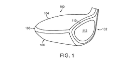
添付図面の図1は、この発明の事例的な実施例に従うゴルフクラブヘッド100の斜視図を示す。より具体的には、図1は、ゴルフクラブヘッド100の前方部分に打撃フェース102を配置し、打撃フェース102の後方部分に本体部分を連結させたゴルフクラブ100を示す。この現行の事例的な実施例においては、ゴルフクラブヘッド100の後方本体部分は、一般的には、クラウン104、ソール106、およびスカート108からなっている。この発明の現行の事例的な実施例において説明される打撃フェース102は、一般的に、打撃フェース102の外部境界の回りに周囲部分110、打撃フェース102の中央領域に中央部分112を有してよい。打撃フェース102の周囲部分110と中央部分112との間の区別はこの現行の事例的な実施例では重要である。なぜならば、打撃フェース102の中央部分112を構築するため、ゴルフクラブヘッド100の、周囲部分110を含む残りの部分のために使用されるものと異なる材料を採用できるからである。上述にかかわらず、周囲部分110も、打撃フェース102と同様に、この発明の趣旨および内容を逸脱しない範囲で、ゴルフクラブヘッド100の残りの部分と異なる材料から構築してゴルフクラブヘッド100の性能をさらに改善して良い。
FIG. 1 of the accompanying drawings shows a perspective view of a
この発明の現行の事例的な実施例において、打撃フェース102の周囲部分110は一般的には比較的大きな第1の密度の金属、例えば、チタンまたはスチールであってよい第1の材料から構築されて良い。これらの材料は、典型的には、ゴルフクラブヘッド100およびゴルフボールの間の衝撃力に耐えるに足るほど充分に強いけれども、重い方であるという傾向がある。より愚弟的には、スチールは、上述した2つの材料のうち重い方であるが、その密度は一般的に約5.0g/cm3および約8.00g/cm3の間である。他方、チタンは、一般的にスチールより密度が小さく、その密度は約4.00g/cm3および約5.00g/cm3の間である。
In the present example embodiment of the present invention, the
そのように多く、ゴルフクラブヘッド内に裁量的な重量があると、ゴルフクラブヘッド100の任意の部分から節約することが可能な任意の量の重量をゴルフクラブヘッド100の重心(CG)および慣性モーメント(MOI)を改善するのに役立てることができる。したがって、図1に示されるこの発明の現行の事例的な実施例は、ゴルフクラブヘッド100の打撃フェース102から重量を節約するために、比較的低い第2の密度の第2の材料を用いて打撃フェース102の中央部分112を構築して良い。より具体的には、打撃フェース102の中央部分112は、この発明から逸脱しない範囲で、約2.7g/cm3の密度のアルミニウム材料、約1.738g/cm3の密度のマグネシウム材料、約1.70g/cm3の密度の複合タイプの材料、または第1の材料の密度より密度が小さい任意の他の材料を使用して構築されて良い。中央部分112を構築するのに使用される第2の材料の第2の密度が小さいので、打撃フェース102の全体の総合重量は顕著に小さくてよく、約15から約25グラムの範囲であってよく、これは、チタンのようなより密度の大きな材料から完全に構築される打撃ゲース102と比較するときに顕著になる。重量の節約は一般に約60mmから約80mmの幅、約25mmから約50mmの高さ、約2.0mmから約3.5mmの厚さの打撃フェース112を基準にして計算される。小さな第2の密度の第2の材料を採用して打撃フェース102の中央部分112を構築すると、ある難題に遭遇することになるかもしれないことを理解することは重要である。なぜならば、低い密度の材料は、ゴルフクラブヘッド100とゴルフボールとの間の衝撃力に耐えるのに充分なほど強くないかもしれないからである。
With such a great amount of discretionary weight within the golf club head, any amount of weight that can be saved from any part of the
この発明は、上述の耐久性の課題に対処するために、第2の材料の軽量性を第1の材料の強度および耐久性と組みあわせて実現できる、2つの異なる材料から成る二重層中央部分112を採用してよい。添付図面の図2はゴルフクラブヘッド200の分解斜視図を示しており、この発明の事例的な実施例に従う二重層中央部分212をより良く説明する。より具体的には、ゴルフクラブヘッド200の分解図により、フェースインサート220およびポケット222が見えるようになる。この発明の現行の事例的な実施例において示されるポケット222は、打撃フェース210の中央部分の全体の厚さを完全に貫通するように設計されていないので、フェースインサート220用に用いられる軽量に第2の材料を裏打ちするように働く金属性の第1の材料の1つの層が残される。フェースインサート220は先に検討したように軽量の第2の材料から製造され、一般的には、ゴルフクラブヘッド200の残りの部分と独立して構築されて良く、ゴルフクラブヘッドが完成した後に、ポケット222内の配置位置に挿入されて良い。最後に、フェースインサート220の幾何形状は一般的にはポケット222の幾何形状を模したものでよく、これにより2つの部品をお互いにシームレスに組み立てることができることに留意することは重要である。
In order to address the above-mentioned durability problem, the present invention provides a double layer central portion made of two different materials that can realize the lightness of the second material in combination with the strength and durability of the first material. 112 may be adopted. FIG. 2 of the accompanying drawings shows an exploded perspective view of the
フェースインサート220は、先に検討したように種々のタイプの軽量密度の材料からなってよいけれども、一般的には、この発明の1つの事例的な実施例においては複合タイプ材料からなって良い。複合タイプ材料は、この発明でそのように呼ばれるように、一般的には、顕微鏡レベルで分離し区別される、顕著に異なる物理的または化学的特性を伴う2またはそれ以上の構成材料から製造された設計材料である。より具体的には、複合タイプ材料は、熱可塑性または熱硬化可能な樹脂材料で含浸された織物またはカーボンファイバーを指して良く、これは樹脂含浸カーボンファイバーとしてより広く知られている。
In general, the
添付図面の図3はこの発明の事例的な実施例に従うゴルフクラブヘッドの前面図を示している。図3の前面図は中央部分312の相対的な寸法、距離、パーセンテージを周囲部分310や打撃フェース302と比較して示す。より具体的には、この発明の当該事例的な実施例においては、打撃フェース302の前面表面面積は、一般的には、約3600mm2より大きく約4000mm2より小さく、より好ましくは約3300mm2より大きく約3900mm2より小さく、最も好ましくは約3800mm2である。他方、中央部分312の前面表面面積は、約2500mm2より大きく約2900mm2より小さく、より好ましくは約2600mm2より大きく約2800mm2より小さく、最も好ましくは、約2700mm2である。最後に、周囲部分310の前面表面面積は、中央部分312の面積を打撃フェース302の面積から差し引いて導出でき、約900mm2より大きく約1300mm2より小さい範囲となり、より好ましくは約1000mm2より大きく約1200mm2より小さく、最も好ましくは約1100mm2である。この事例的な実施例において示される中央部分312は、この発明の趣旨および内容を逸脱しない範囲で、中央領域の被覆率を向上させるために打撃フェース302の外部幾何形状と模してものであってよい。
FIG. 3 of the accompanying drawings shows a front view of a golf club head according to an exemplary embodiment of the present invention. The front view of FIG. 3 shows the relative dimensions, distance, and percentage of the
軽量の第2の材料から成る中央部分312に充分な大きさのポケットを設けるために、中央部分312は打撃フェース302の件茶名部分を占めなければならない。換言すれば、中央部分の打撃フェースに対する比は約0.65より大きくなくてはならず、より好ましくは0.70より大きく、最も好ましくは約0.75より大きくなくてはならない。中央部分の打撃フェースに対する比は、中央部分312の前面表面面積を打撃フェース302の前面表面面積で割ったものとして定義されつぎの式(1)で示される。
中央部分の打撃フェースに対する比=(中央部分の前面表面面積)/(打撃フェースの前面表面面積) 式(1)
最後に、打撃フェース302は中央部分312と周囲部分313とに分離でき、ここで、中央部分312は先に述べた第2の材料で充填できるポケットを規定する。
In order to provide a sufficiently large pocket in the
Ratio of the central portion to the striking face = (front surface area of the central portion) / (front surface area of the striking face) Equation (1)
Finally, the
図3において示されるゴルフクラブヘッド300の前面図は、中央部分312の打撃フェース302の周囲からのオフセットを示し、これはオフセット距離d1にあり、これは打撃フェース302の周囲と中央部分312の周囲との間の距離として定義される。現行の事例的な実施例に示されるように、オフセット距離d1は、一般的に、中央部分312内のポケットの大きさを定義するのに役立ち、これはゴルフクラブヘッド300の性能を変更するためにポケット内に充填するのに採用できる第2の材料の量を決定する。この発明の1つの事例的な実施例においては、オフセット距離d1は、一般的には、約0.5インチより小さく、より好ましくは約0.33インチより小さく、最も好ましくは0.25インチより大きくて良いが、この発明の範囲および内容から逸脱しない。図3に示すゴルフクラブヘッド300は打撃フェース302の周囲全体に渡って一定のオフセット距離を示すけれども、この発明の範囲および内容から逸脱しない範囲で重量除去および耐久性の正確なバランスを見いだすように可変してよい。
The front view of the
添付図面の図4はこの発明の事例的な実施例に従うゴルフクラブヘッド400の図3に示される断面線A−A'に沿う断面図を示す。ゴルフクラブヘッド400のこの断面図によれば、ゴルフクラブヘッド400の中央部分412のポケット422に加えて後方部分423も明瞭である。ポケット422の内部の軽量の第2の材料により実現される重量の節約は、後方部分423内の金属性材料の強度および耐久性によってバランスされる必要があるので、この発明においては、ポケット422および後方部分423の相対厚さが重要である。この発明の事例的な1実施例においては、ポケット422の深さd2は一定に維持され、約0.2mmより大きく、約2.0mmより小さく、より好ましくは約0.5mmより大きく、約1.5mmより小さく、最も好ましくは約1.0mmである。ポケット422内に軽量の第2の材料を使用することにより犠牲となる耐久性とバランスさせるために、後方部分423の厚さd3は一般的にはゴルフクラブヘッド400がゴルフボールとの衝撃に耐えることを可能にする厚さを維持しなければならない。したがって、後方部分423の厚さd3は一般的には約1.5mmより大きく、約3.0mmより小さく、より好ましくは約1.75mmより大きく、約2.75mmより小さく、最も好ましくは約2.25mmである一定の厚さである。
FIG. 4 of the accompanying drawings shows a cross-sectional view of the
厚さは先に説明されたけれども、d2およびd3の間の相対的な厚さの比がここではより重要な数であることに留意されたい。これは、ポケット422の深さd2の相対厚さとともに後方部分423の厚さd3を定量化する。この比は、この出願においては「打撃厚さ比」と呼ばれ、打撃フェース402の耐久性を維持しながら打撃フェース402から不必要な重量を減殺するゴルフクラブヘッド400の性能と間接的に定量化する。この出願でそのように呼ばれる、打撃厚さ比は、より具体的にはポケット422の深さd2を後方部分423の厚さd3で割ったものとして定義され、これは以下の式(2)のとおりである。
打撃厚さ比=(ポケットの深さ(d2))/(後方部分の厚さ(d3)) 式(2)
この事例的な実施例で説明したように、打撃厚さ比は一般的には約1.0より小さく、より好ましくは、約0.8より小さく、最も好ましくは約0.7より小さい。
Note that although the thickness has been described earlier, the relative thickness ratio between d2 and d3 is a more important number here. This quantifies the thickness d3 of the rear portion 423 along with the relative thickness of the pocket 422 depth d2. This ratio, referred to in this application as the “thickness ratio”, is indirectly quantified with the ability of the
Stroke thickness ratio = (depth of pocket (d2)) / (thickness of rear part (d3)) Formula (2)
As described in this exemplary embodiment, the striking thickness ratio is generally less than about 1.0, more preferably less than about 0.8, and most preferably less than about 0.7.
添付図面の図5は図4に示す円形の領域Bの拡大断面図を示す、より具体的には、図5に示されるゴルフクラブヘッド400の打撃フェース402の拡大図により、後方部分423およびポケット422のそれぞれの相対的な厚さd3およびd2がより明瞭になる。上述に加えて、図5は、第2の密度の第2の材料から構築されるフェースインサート520をポケット522の配置位置から伊豆して示している。図5に関して初めに認識しておくべきことの1つは、フェースインサート520の相対寸法および形状は合理的なことにポケット522の寸法および形状と類似しているということである。他の観点から見ると、フェースインサート520は、一般的には、この発明の範囲および内容から逸脱しない範囲で、ポケット522内にフィットできるような寸法および形状で設計されてよい。より具体的には、図5から理解できるように、フェースインサートの厚さd2はポケット522の深さd2と実質的に類似で良く、この類似性は図示のとおりである。
FIG. 5 of the accompanying drawings shows an enlarged cross-sectional view of the circular region B shown in FIG. 4, and more specifically, an enlarged view of the
図5からわずかに見て取れるけれども、現代のゴルフクラブヘッドの打撃フェース502の部分は一般的にわずかの曲がりを伴い中心からずれた打撃により起因する不利益を訂正するようになっていてよいことは広く知られている。現代のゴルフクラブヘッドの打撃フェース502の部分のこのようなわずかな曲がりは、ゴルフクラブヘッドのバルジおよびロールとしてより広く知られており、これは水平方向または垂直方向のいずれから基準点が取られているかによって左右される。打撃フェース502および/またはポケット522の厚さは一般的には打撃フェース502の前面表面から決定されてよいことに注意することが大切であり、これは、ポケット522が打撃フェース520の前面と同一のバルジおよびロールの曲がりを伴うことを意味する。ポケット内のバルジおよびロールの曲率半径を維持することは、凸形状の表面は平坦または凹形状のポケット522より衝撃力を吸収するので、ゴルフクラブヘッドの打撃フェースの耐久性にとって有利である。ただし、この発明の範囲および内容から逸脱しないすべての実施例においてポケット522が凸形状である必要はないことに留意すべきであり、とくに、打撃フェース502がすでに充分に耐久性があって衝撃力を吸収できるときには、ポケット522の内部表面は平坦であっても、さらには凹形状であってもよい。
Although slightly visible in FIG. 5, it is widely understood that the portion of the
フェースインサート520およびポケット522の寸法および形状が相対的に類似しているので、一般的なフェースインサート520のポケット522内への結合を助長できる。ただし、この持ち前の要素の幾何形状を利用した機構的な結合に加えて、接着タイプの材料を採用してフェースインサート520およびポケット522の間の結合を一般的に助長することができる。接着タイプの材料は、この出願において検討されるように、一般的には合成タイプの接着剤で良いけれども、接着タイプの材料は、天然接着剤、接触接着剤、仮接着剤、ホットメルト接着剤、UV光硬化接着剤、圧力感応接着剤、または、この発明の範囲および内容を逸脱しない範囲で、ポケット522内にフェースインサート520を保持する化学結合を形成することが可能な任意のタイプの接着剤であってもよい。
Because the size and shape of the
添付図面の、図6、図6A、図6B、図6C、および図6Dはこの発明の他の代替的な実施例を示しており、ここでは、ポケット622が、フェースインサート620およびポケット622の間の周囲係合部分Cの回りにアンダーカット628を含み、これが上述の2つの部品の間の結合をさらに助長する。より具体的には、図6A、図6B、図6C、および図6Dは、この発明の範囲および内容から逸脱しない範囲でフェースインサート620をポケット622内に連結するのを助長するのに採用できる種々のタイプのアンダーカット628を拡大して示す。種々のポケット622の幾何形状について詳細に説明するのに先立って、そのようなアンダーカット628を具備するポケットにフェースインサート620を挿入する手法について簡単に検討することがこの発明の発想を説明するのに役立つであろう。図6、図6A、図6B、図6C、および図6Dを参照すると、アンダーカット628を超える大きな径のフェースインサート620を配置することは物理的に困難であることが理解できるであろう。したがって、フェースインサート620を、アンダーカット628を具備するポケット622内に挿入するには、フェースインサート620を形成する複合材料を硬化前にポケット622に配置する必要があるであろう。樹脂含浸材料は、堅固な本体を伴う金属性材料と異なり、一般的には、樹脂が硬化されるまで、屈曲させやすい構造を有してよい。したがって、上述から理解できるように、複合タイプの材料をフェースインサート620を構築するのに使用するのであれば、複合材料の硬化前の屈曲性によってフェースインサートをポケット622に入れ込むことが可能になる。
FIGS. 6, 6A, 6B, 6C, and 6D of the accompanying drawings illustrate another alternative embodiment of the present invention in which the
フェースインサート620を構築するのに使用される樹脂含浸複合タイプ材料の屈曲性に加えて、樹脂含浸複合材を形成するために多層の繊維材料が使用されるので、アンダーカット628の回りでポケットを樹脂含浸複合材で充填することが可能になる。より具体的には、樹脂含浸複合材料は薄い層の樹脂繊維を上下に重ねて構成されるので、種々の繊維層がポケット622を充填してアンダーカット628にまで至る。ただし、この発明の範囲および内容から逸脱しない範囲で行われる。
In addition to the flexibility of the resin-impregnated composite type material used to construct the
図6A、図6B、図6C、および図6Dは、周囲拡大部Cの種々の拡大図を示し、この発明の種々の実施例に従う種々のアンダーカット628の幾何形状をより明瞭に示す。より具体的には、図6Aは、フェースインサート620をポケット622に固着するのに役立つV形状のアンダーカット628を示す。図6Bは、アンダーカット628の外部突端近くに平坦部分を伴い、衝撃時の高ストレスを伴う鋭い角部分を除去したV形状のアンダーカット628を示す。図6Cは、この発明の他の代替的な実施例を示し、ここでは、U形状のアンダーカット628を用いてフェースインサート620をポケット622に固着できる。最後に、図6Dは、この発明の他の代替的な実施例を示し、ここでは、U形状のアンダーカット628平坦な突端を伴って衝撃時にひびや割れを起こす鋭い角部分を除去している。
6A, 6B, 6C, and 6D show various enlarged views of the peripheral enlargement C, and more clearly show the various undercut 628 geometries according to various embodiments of the present invention. More specifically, FIG. 6A shows a V-shaped undercut 628 that helps secure the
この時点で、ゴルフクラブヘッドの打撃フェース602の部分にポケット622を設けると、すぐに理解可能なものでない付加的な性能上の利益がもたらされることを理解することは重要である。より具体的には、上述のこのタイプの幾何形状から裁量的な重量を形成することにより実現される明らかな性能上納利益に加えて、このタイプのポケット622を採用することは、ゴルフクラブヘッドの所望の音響を維持するのを可能にするであろう。ゴルフクラブヘッドの音響は、定量化することは困難であるけれども、ゴルフクラブヘッドの感受される性能に大いに影響を与える存在である。複合タイプの材料は金属タイプの材料と著しく異なる音響を呈するであろうから、ゴルフクラブヘッドの音響を調整して全部金属性の打撃フェースを具備するゴルフクラブヘッドと比較的類似するようになすことは、この発明のおいて重要であろう。
At this point, it is important to understand that providing a
添付図面の図7は、完全に金属性の打撃フェースを具備する従来のゴルフクラブヘッドの信号電力図を示し、所望の音を実現するゴルフクラブヘッドの音響特性を図説する。より具体的には、図7は、従来のゴルフクラブヘッドがゴルフボールに衝突したときに生成される音の電力752を周波数754の関数として把握する。この電力752および周波数754はゴルフクラブヘッドの種々の部品、例えば、クラウン、ソール、フェース、またはゴルフクラブヘッドの任意の他の部品のゴルフボールとの衝突時の振動を定量化する。図7から理解できるように、全部が金属性の打撃フェースを具備するこの従来のゴルフクラブヘッドは約4,000ヘルツに音響電力752の第1ピーク756を生成するであろう。音響電力752のピーク756は、全部が金属性の打撃フェースを具備するこの従来のゴルフクラブヘッドにおいて示されるように、一般的には、全体の音響電力出力は約0.2ワットであろう。したがって、上述に基づけば、全部が金属性の打撃フェースを具備するゴルフクラブヘッドの所望の音響は電力の第1ピークを約3,500ヘルツより大きく、より好ましくは約3,750ヘルツより大きく、最も好ましくは約4,000ヘルツより大きい周波数としてよいことが観察できる。
FIG. 7 of the accompanying drawings shows the signal power diagram of a conventional golf club head with a fully metallic striking face and illustrates the acoustic characteristics of the golf club head that achieves the desired sound. More specifically, FIG. 7 grasps the power of
添付図面の図8は、全部が複合材の打撃フェースを具備する従来のゴルフクラブヘッドの信号電力図を示し、このタイプのゴルフクラブヘッドの音響特性が劇的に変化することを説明している。図8から、全部が複合材の打撃フェースを具備する従来のゴルフクラブヘッドから生成される音響の電力は、金属性打撃フェースを具備する伝統的な従来のゴルフクラブヘッドの電力に較べてり著しく小さいことが、即座にわかる。図7の図面と同一のスケールでプロットされるときにはほとんど気づかないけれども、一般的には、全部が複合材の打撃フェースを具備する従来のゴルフクラブヘッドは音響電力の第1ピーク856を約3,000ヘルツに伴っている。全部が複合材の打撃フェースを具備する従来のゴルフクラブヘッドに置いて示される、ピーク856の音響電力852は一般的には約0.002ワットより小さい全体の音響電力852の出力を伴って良い。したがって、完全に金属性の打撃フェースを具備する従来のゴルフクラブヘッドの、図7に示すような、信号電力図と較べたときには、ゴルフクラブヘッドの打撃フェースを複合材料で完全に置き換えるとゴルフクラブヘッドの所望の音響が顕著に犠牲になることが理解できるであろう。
FIG. 8 of the accompanying drawings shows the signal power diagram of a conventional golf club head with an all-composite striking face, illustrating the dramatic change in the acoustic characteristics of this type of golf club head. . From FIG. 8, the acoustic power generated from a conventional golf club head with an all-composite striking face is significantly greater than that of a traditional conventional golf club head with a metallic striking face. You can see that it is small. Although not noticeable when plotted on the same scale as the drawing of FIG. 7, in general, a conventional golf club head with an all-composite striking face has a
添付図面の図9を参照すると、この発明に従うゴルフクラブヘッドの信号電力図を理解できる。一瞥しただけで、この発明の信号電力図は、全部が金属性の打撃フェースを具備する従来のゴルフクラブヘッドの、図7に示す信号電力図により似ていることが理解できる。より具体的には、この発明のゴルフクラブヘッドの信号電力図は、音響電力952中の第1ピーク956が約3,500ヘルツより大きく、かつ約4,500ヘルツより小さく、より好ましくは約3,750ヘルツより大きく、かつ約4,250ヘルツより小さく、最も好ましくは約4,000ヘルツで存在してよい。打撃フェースにポケットを具備する、この発明のゴルフクラブヘッドの音響電力952のピーク956は、約0.1ワットより大きく、より好ましくは約0.125ワットより大きく、最も好ましくは約0.15ワットの全体の音響電力952の出力を実現して良い。この発明のゴルフクラブヘッドの信号電力図は、全部が金属性のフェースと具備する従来のゴルフクラブヘッドの信号電力図と顕著に類似性を示すので、この発明のゴルフクラブヘッドの音響は、複合タイプのフェースインサートを伴っているにもかかわらず、好ましいものである。
Referring to FIG. 9 of the accompanying drawings, a signal power diagram of a golf club head according to the present invention can be understood. At a glance, it can be seen that the signal power diagram of the present invention is more similar to the signal power diagram shown in FIG. 7 for a conventional golf club head with an all-metal hitting face. More specifically, the signal power diagram of the golf club head of the present invention shows that the
種々のゴルフクラブヘッドによりもたらされる音響の望ましさは、信号電力図における上述した値に左右されるので、これらの値を相互の関係として定量化して比較を容易にすることはより簡単であろう。以下の式(3)は、ピーク電力の周波数に対する比を生成し、これは容易に定量化可能な方法でゴルフクラブヘッドの所望の音響を把握する。
ピーク電力の周波数比=(ピーク電力)/(ピーク電力が起こる周波数) 式(3)
この発明の事例的な実施例に従うゴルフクラブヘッドのピーク電力周波数比は一般的には2.5×10⁻⁵ワット/ヘルツより大きく、約5×10−5ワット/ヘルツより小さく、より好ましくは、3.0×10−5ワット/ヘルツより大きく、約4.5×10−5ワット/ヘルツより小さく、最も好ましくは約4.0×10−5ワット/ヘルツであってよい。
The desirability of the sound provided by the various golf club heads depends on the values mentioned above in the signal power diagram, so it would be easier to quantify these values as a relationship and to facilitate comparison. . Equation (3) below produces a ratio of peak power to frequency that captures the desired sound of the golf club head in a readily quantifiable manner.
Frequency ratio of peak power = (peak power) / (frequency at which peak power occurs) Equation (3)
The peak power frequency ratio of a golf club head according to an exemplary embodiment of the present invention is generally greater than 2.5 × 10 −5 watts / hertz and less than about 5 × 10 −5 watts / hertz, more preferably Greater than 3.0 × 10 −5 watts / hertz, less than about 4.5 × 10 −5 watts / hertz, and most preferably about 4.0 × 10 −5 watts / hertz.
ピーク電力周波数比は先に説明され、これはゴルフクラブのゴルフボールとの衝突時の音響を定量化するけれども、ゴルフクラブヘッドの寸法は考慮されていない。ゴルフクラブヘッドの音響は一般的にはゴルフクラブヘッドのゴルフボールとの衝突時に振動により引き起こされるので、ゴルフクラブヘッドの寸法は、ゴルフクラブヘッドを用いてゴルフボールを叩くときにそのような振動に利用可能な表面面積の量を決定するための重要なファクタである。したがって、ゴルフクラブヘッドの音響を定量化する上で認識すべく他の重要な比は、第1ピークの周波数のゴルフクラブヘッドの体積に対する比であろう。好ましい音響は何かというさきの検討と同様に、この発明に従うゴルフクラブヘッドでは、一般的に、周波数における第1ピークは、約3,500ヘルツより大きく、かつ約4,500ヘルツより小さい範囲で、より好ましくは約3,750ヘルツより大きく、かつ約4,250ヘルツより小さい範囲で、最も好ましくは約4,000ヘルツで起こり、これについては上述した。この発明に従うゴルフクラブヘッドの全体の容積は、一般的には、約400立方センチメートル(cc)より大きく、かつ、500ccより小さく、より好ましくは、約420ccより大きく、約580ccより小さく、最も好ましくは約460ccであってよい。上述の数値を参照すると、第1ピーク周波数の体積比の関係は一般的には約7.0ヘルツ/ccより大きく、約15.0ヘルツ/ccより小さく、より好ましくは、約9.0ヘルツ/ccより大きく、約13.0ヘルツ/ccより小さく、最も好ましくは約8.0ヘルツ/ccであってよい。第1ピーク周波数の体積比は以下の式(4)で定義される。
第1ピーク周波数の体積比=(第1ピーク周波数)/(体積) 式(4)
The peak power frequency ratio is described earlier, which quantifies the acoustics of a golf club upon impact with a golf ball, but does not take into account the size of the golf club head. Since the golf club head sound is generally caused by vibrations when the golf club head collides with a golf ball, the size of the golf club head is such vibration when hitting the golf ball with the golf club head. It is an important factor for determining the amount of surface area available. Thus, another important ratio to recognize in quantifying golf club head sound would be the ratio of the frequency of the first peak to the volume of the golf club head. Similar to the discussion of what preferred sound is, golf club heads according to the present invention generally have a first peak in frequency in the range of greater than about 3,500 Hertz and less than about 4,500 Hertz. More preferably in the range of greater than about 3,750 hertz and less than about 4,250 hertz, most preferably at about 4,000 hertz, as described above. The overall volume of a golf club head according to the present invention is generally greater than about 400 cubic centimeters (cc) and less than 500 cc, more preferably greater than about 420 cc, less than about 580 cc, and most preferably about It may be 460 cc. Referring to the above figures, the volume ratio relationship of the first peak frequency is generally greater than about 7.0 hertz / cc, less than about 15.0 hertz / cc, more preferably about 9.0 hertz. Greater than / cc, less than about 13.0 hertz / cc, and most preferably about 8.0 hertz / cc. The volume ratio of the first peak frequency is defined by the following formula (4).
Volume ratio of first peak frequency = (first peak frequency) / (volume) Equation (4)
第2の密度の第2の材料が充填されるポケットを採用すると、上述のように、ゴルフクラブヘッドの打撃フェースから重量を節約し、また、音響特性を改善することに加えて、ゴルフクラブヘッドの特徴時間(CT)を増加させることにより、ゴルフボールをより遠くに打撃できるゴルフクラブヘッドを製造する上で付加的な利点を実現する。CTは、現在、ゴルフ産業において知られているように、一般的には、種々の速度を模した種々の高さから振り子を落下させた後、振り子がゴルフクラブヘッドに接触している時間の量と関係する。速度および時間の値が、振り子に取り付けられた加速度計により把握され、その後、一般的には、速度の関数としてプロットされる。測定のスロープを伴う線形な傾向線が種々のデータ点から形成されて良く、最終的なy切片がゴルフクラブヘッドのCT値をなす。ゴルフクラブヘッドのCT値を求めるのに使用される正確な装置および手順に関するより詳細な説明は米国特許第6,837,094号(Pringle等)に見い出すことができ、その内容は参照してここに組み入れる。 Employing a pocket filled with a second material of a second density saves weight from the striking face of the golf club head and improves the acoustic characteristics, as described above, in addition to the golf club head. By increasing the characteristic time (CT), an additional advantage is realized in manufacturing a golf club head capable of hitting a golf ball farther. CT is generally known in the golf industry as a general rule of thumb when the pendulum is in contact with the golf club head after dropping the pendulum from various heights simulating various speeds. Related to quantity. Velocity and time values are captured by an accelerometer attached to the pendulum and then typically plotted as a function of velocity. A linear trend line with a slope of measurement may be formed from the various data points, and the final y-intercept forms the golf club head CT value. A more detailed description of the precise apparatus and procedure used to determine the golf club head CT value can be found in US Pat. No. 6,837,094 (Pringle et al.), The contents of which are hereby incorporated by reference. Incorporate
添付図面の図10は、'94特許において説明されるステップに従ってゴルフクラブヘッドの打撃フェースの柔軟性を測定するポータブル装置を利用して得た種々の接触時間結果をグラフ表示するものである。より具体的には、図10は、この発明に従う事例的なゴルフクラブヘッドの打撃フェースの特性時間結果をy軸に沿って示し、それぞれのデータ点1062の各々の振り子の速度をx軸に沿って示すものである。振り子に取り付けられた加速度計により測定される振り子の速度は、以下の式(5)により定量化される線形な関係を生成するうえで予期される誤差を最小化するために、−0.329の指数値を採っていることに留意されたい。
T=A+BV−k 式(5)
ここでTは、振り子の速度が、記録される最高値の5%から95%に上昇するのに要する時間であり、Bは、種々のデータ点1062により形成された傾向線1064のスロープであり、Vは種々のデータ点1062の振り子テストの速度であり、kはゴルフクラブヘッドの切片値における誤差を最小化するための指数調整ファクタである。傾向線1064およびy軸の間の交点は、ここではAとして特定され、上述のT、B、およびVの値から決定でき、一般的には、USGAにより採用される最終的なCT値であってよく、これはゴルフボールと衝突する際にゴルフクラブヘッドが撓む能力に関連する。
FIG. 10 of the accompanying drawings graphically displays various contact time results obtained using a portable device that measures the golf club head striking face flexibility according to the steps described in the '94 patent. More specifically, FIG. 10 shows a characteristic time result of a hitting face of an exemplary golf club head according to the present invention along the y-axis, and the pendulum speed of each
T = A + BV −k formula (5)
Where T is the time it takes for the pendulum speed to rise from 5% to 95% of the recorded maximum, and B is the slope of the
ここでいうCT値は交点Aによって決定されるので、振り子テストから個々のデータ点1062の種々のCT結果から形成される傾向線1064のスロープBが重要であることに留意されたい。この発明は、ゴルフクラブの打撃フェース部分にあるポケットの中に小さな第2の密度の複合材を特定の量だけ利用しているので、種々のデータ点から形成される傾向線1064のスロープBは一般的には伝統的な従来のゴルフクラブヘッドのスロープより急峻であろう。より具体的には、種々のデータ点1062の傾向線1064から形成されるスロープはここでは「特徴時間スロープ」として知られている。「特徴時間スロープ」はこの発明でさきに定義されるように、一般的には、約5より大きく、約50より小さく、より好ましくは約10より大きく、約45より小さく、さらに好ましくは、約12.5より大きく、約30より小さく、最も好ましくは約15より大きく、約20より小さく、これは図10に示すとおりである。特徴時間スロープの傾向線1064の単位は先には特に検討しなかったけれども、それは一般的にはマイクロ秒で表される時間の単位を速度の値で割って、−0.33乗することにより導出できる。傾向線1064の単位の最終的な結果は一般的には(マイクロ秒)/(秒/メータ)または当該式の任意の他の単純化した形態であって良く、ただし、この発明の範囲および内容を逸脱しないものとする。CTテストに関するより多くの情報は、合衆国ゴルフ協会(USGA)により定義され、Technical Description of the Pendulum Test、Revised Version、Discussion of Points Raised During Notice & Comment Period(2003年、11月)に見いだすことができ、その内容は参照してここに組み入れる。
Note that since the CT value here is determined by the intersection A, the slope B of the
ゴルフクラブヘッドの打撃フェース部分内に形成されるポケットに採用できる種々の幾何形状に関する先の検討に戻り、ここでは図11を参照する。添付図面の図11は、凹状の幾何形状を際賞して良いポケット1122を具備するゴルフクラブヘッドの断面図を示す。凹状幾何形状は後方部分1102の厚さを減少させるけれども、薄い後方部分1123は全体の打撃フェース1102に付加的な変形を実現し、これがゴルフクラブヘッドの性能を向上させることになる。ポケット1122の厚さは一般的には図11にd3として示されてよいけれども、この厚さは、この発明の範囲および内容を逸脱しない範囲で、約0.2mmから約3.5mmであってよい。
Returning to the previous discussion regarding the various geometries that can be employed in the pockets formed in the striking face portion of the golf club head, reference is now made to FIG. FIG. 11 of the accompanying drawings shows a cross-sectional view of a golf club head with
添付図面の図12はこの発明の他の代替的な実施例に従うポケット1222を具備するゴルフクラブヘッドの断面図を示す。より具体的には、ポケット1222の後方部分1223は可変厚さを伴ってよく、これによりポケット1222内のインサート1220の幾何形状に影響を与えることなく、大きなスイートスポットを実現できる。可変厚さの打撃フェースを具備するゴルフクラブヘッドの利点に関するより詳細な検討は米国特許第6,605,007号(Bissonnette等)に見い出すことができ、その内容は参照してここに組み入れる。この発明の当該事例的な実施例に従う後方部分1223は2つの異なる厚さd5およびd6を伴って良く、より厚い部分d5は打撃フェース1201の中央の近くに配置される。上述に限らず、この発明の範囲および内容から逸脱しない範囲で、多くの他の形態の厚さプロファイルをより多くの個別のセクションを伴って採用することができ、単に後方部分が可変厚さであればよい。最後に、ポケット1222の厚さおよびフェースインサート1220の厚さは、この発明の範囲および内容から逸脱しない範囲で、すべて実質的に不変で一定厚さd2であってよい。
FIG. 12 of the accompanying drawings shows a cross-sectional view of a golf club head having a
添付図面の図13はこの発明の他の代替的な実施例に従うポケット1322およびフェースインサート1320の他の代替的な幾何形状を伴うゴルフクラブヘッドの断面図を示す。より具体的には、この発明の当該事例的な実施例においてフェースインサート1320は可変厚さを伴ってゴルフクラブヘッドの打撃フェース1320の性能を向上させて良い。フェースインサート1320に関して可変厚さを実現するために、後方部分1323は一定の厚さを維持してフェースインサート1320の可変厚さを実現してよい。後方部分1323の一定厚さを維持するために、この発明の代替的な実施例は、一般的には、後方部分1323の中央部分の近くで屈曲してフェースインサート1320の厚い部分に適合するようになす後方部分1323を実現して良い。
FIG. 13 of the accompanying drawings shows a cross-sectional view of a golf club head with other alternative geometries of
添付図面の図14は、この発明の他の代替的な実施例に従うポケット1422およびフェースインサート1420の他の代替的な幾何形状を伴うゴルフクラブヘッドの断面図を示す。より具体的には、この発明の事例的な実施例においてフェースインサート1420は可変厚さを伴ってゴルフクラブヘッドの打撃フェース1420の性能を向上させてよい。後方部分1423は、打撃フェース1420をサポートする代替的な手法を提供し、打撃フェース1402の中央部分で薄くなる可変厚さを実現する。この実施例は、好ましいことに、薄い中央部分がより撓むので、中央部分の曲げ剛性を大きくできて好ましい。
FIG. 14 of the accompanying drawings shows a cross-sectional view of a golf club head with other alternative geometries of
添付図面の図15は、この発明の他の代替的な実施例に従うポケット1522およびフェースインサート1520の他の代替的な幾何形状を伴うゴルフクラブヘッドの断面図を示す。より具体的には、この発明の当該実施例は、打撃フェース1520の中央部分で厚さが大きい後方部分1523を具備してゴルフクラブヘッドの耐久性を増大させる。したがって、打撃フェース1502の中央部分で後方部分1523の厚さを増大させるために、フェース人サーと1520の厚さは一般的に中央部分で薄くなっていて良い。この実施例はゴルフクラブヘッドの耐久性の改善が必要な場合に好ましいであろう。
FIG. 15 of the accompanying drawings shows a cross-sectional view of a golf club head with
添付図面の図16は、この発明の他の代替的な実施例に従い、異なる幾何形状を採用して打撃ベース1602を形成するゴルフクラブヘッドの断面図を示す。より具体的には、後方部分1623が薄いけれども完全な打撃フェース1620を形成し、これがフェースインサート1620によって被覆される。このフェースインサート1620は、サイズは通常ではないけれども、ゴルフクラブヘッドの打撃フェース1602の部分から不必要な重量を除去するという同一の目的に役立つ。この発明の当該実施例は、この発明の範囲および内容から逸脱しない範囲で、後方部分1623の構造上の一体性を維持しつつゴルフクラブヘッドの打撃フェース1602から負引くような重量を除くという点で従来のゴルフクラブヘッドに対して利点を有する。
FIG. 16 of the accompanying drawings shows a cross-sectional view of a golf club head that employs different geometries to form a
添付図面の図17は、この発明の他の代替的な実施例に従い、若干異なる幾何形状を採用して打撃ベース1702を形成するゴルフクラブヘッドの断面図を示す。より具体的には、この発明の当該実施例は、打撃フェース1702の両端に2つの個別の後方部分1723を採用して中央領域ではフェースインサート1720を非支持状態にする。この発明の当該代替的な実施例は完全な後方部分1723と関連する重量を完全に除去するのに役立ち、さらに、ゴルフクラブヘッドの打撃フェース1702に関連する不必要な重量も減少させることができる。
FIG. 17 of the accompanying drawings shows a cross-sectional view of a golf club head that employs a slightly different geometry to form a
添付図面の図18は、この発明の他の代替的な実施例に従い、異なる幾何形状を採用して打撃ベース1802を形成するゴルフクラブヘッドの断面図を示す。図18に示されるこの発明の当該実施例は、接着点を打撃フェース1802の衝撃部分から除去またはシフトさせるためにフェースインサート1820の周囲をゴルフクラブヘッドのクラウンおよびソール側にずらした。接着点を打撃フェース1802からずらすと、連結部分を最も応力が大きな部分から移動させて、必要な接着強度を減少させることができるという点で、ゴルフクラブヘッドの性能上有利となる。図18から理解できるように、後方部分1823はゴルフクラブヘッドのクラウンおよびソールの方向にずらされて、この目的を実現する。ただしこの発明の範囲お呼び内容から逸脱しないものとする。
FIG. 18 of the accompanying drawings shows a cross-sectional view of a golf club head that employs different geometries to form a
添付図面の図19は、この発明の他の代替的な実施例に従い、異なる幾何形状を採用して打撃ベース1902を形成するゴルフクラブヘッドの断面図を示す。より具体的には、図19から理解できるように、フェースインサート1920は、ゴルフクラブヘッドの打撃フェースを完全に包囲してゴルフクラブヘッドの打撃フェースから連結部をシフトさせて良い。ただし、図19に示されるゴルフクラブヘッドは、金属性の後方部分1923もフェースインサート1920の部分的な後方サポートを構成する点で、付加的な性能上の利点を実現する。上述の特徴に加えて、この発明の当該事例的な実施例において示されるフェースインサート1920は、この発明の範囲および内容から逸脱することなく、厚い中央部分を採用してスイートスポットの大きさを改選して良い。
FIG. 19 of the accompanying drawings shows a cross-sectional view of a golf club head that employs different geometries to form a
ここで図17〜19に示されるゴルフクラブヘッドは、図17〜19に示されるゴルフクラブヘッドにより生成されるポケットは後方部分を具備しないという点で、この発明の先に検討した種々の実施例から若干異なっている点に留意されたい。ポケットが金属性後方部分によりサポートされている場合には、複合タイプの材料の種々の層の内部の破損の主たる原因は、複合繊維の個々の層の剥離によるであろう。しかしながら、ポケットが後方部分によってサポートされていない場合には、主たる懸念は、複合材料自体の耐久性であり、この結果、複合タイプの材料の強度および耐久性が主たる懸念になる。ほとんどどのような種類の樹脂含浸カーボンファイバーも顕著な重量節約上の利点があるという事実にかかわらず、すべてのタイプの樹脂含浸カーボンファイバーがゴルフクラブヘッドに採用されるために必要な耐久性の要求を満たすものではない。種々のタイプの樹脂含浸カーボンファイバーを理解するために、添付図面の図20を参照することが役に立ち、これは、カーボンファイバー含浸繊維内のファイバーの応力および歪みチャート2000を示し、この発明に従う第2の材料として使用するのに適するであろう樹脂含浸カーボンファイバーの応力および歪みの間の関係を図説するのに役立つ。
Here, the golf club head shown in FIGS. 17-19 has various embodiments previously discussed in that the pocket produced by the golf club head shown in FIGS. 17-19 does not have a rear portion. Note that there is a slight difference. If the pocket is supported by a metallic back portion, the main cause of failure within the various layers of composite type material will be due to delamination of the individual layers of the composite fiber. However, if the pocket is not supported by the rear portion, the main concern is the durability of the composite material itself, which results in the main concerns of the strength and durability of the composite type material. Despite the fact that almost any kind of resin-impregnated carbon fiber also has an advantage over significant weight savings, all types of resin-impregnated carbon fiber required durability required in order to be employed in the golf club head It does not satisfy. To understand the various types of resin-impregnated carbon fibers, it is helpful to refer to FIG. 20 of the accompanying drawings, which shows a stress and
初めに、応力および歪みチャート2000を参照すると、複合タイプの材料の繊維の応力及び歪みの間の関係2030は線形弾性から破壊へという特性を有して良い。複合材料の繊維における線形弾性から破壊へという特性は、これにより、複合材料の物理的な寸法を変化させない純粋な弾性変形を可能にする点で、一般的には、非線形弾性から破壊へという特性より好ましいであろう。複合材の繊維における、この種の純粋に線形な弾性から破壊へという特性は、非線形の弾性から破壊へというものに較べてより好ましい、なぜならば、線形弾性から破壊への特性を有する壊れやすい繊維は、一般的には、非線形弾性から破壊へという特性の壊れやすい繊維により実現可能な降伏応力より大きな最大抗張力を実現できるからである。複合材料の繊維が線形弾性から破壊へという特性を示すのに加えて、図20の応力および歪みの間の関係2030も、当該発明に用いられる複合材料の理想的な繊維の強度および弾性を示す。より具体的には、図20は使用される複合材料の繊維が一般的には約4.5GPaより大きく、6.0GPaより小さく、より好ましくは、約4.5GPaより大きく、約5.5GPaより小さく、最も好ましくは約4.9GPaの引張強度を有することを示すであろう。上述した引張強度と組みあわせて、複合材料は一般的に引張弾性モジュラスを有して良く、これは応力および歪みの関係2030のスロープにより決定され、約200GPaより大きく約300GPaより小さく、より好ましくは約225GPaより大きく約275GPaより小さく、最も好ましくは約241GPaである。ここでは、引張強度および引張モジュラスは、すべて、複合材料の繊維の重要な特性であるけれども、繊維をこの発明に適切なものになす決定因子は、歪みから破壊へのパーセンテージにかかっている。歪みから破壊へのパーセンテージは、当該事例的な実施例でそのように呼ぶように、一般的には、繊維の引張強度を繊維の引張弾性モジュラスで割ったものとして定義され、より具体的には以下の式(6)で説明される。
(引張強度)/(引張弾性モジュラス)=歪みから破壊へのパーセンテージ 式(6)
First, referring to the stress and
(Tensile Strength) / (Tensile Elastic Modulus) = Percentage from strain to fracture Equation (6)
歪みから破壊へのパーセンテージは、図20の当該事例的な実施例において示されるように、また、さきの引張強度および引張弾性モジュラスの値に基づいて、一般的には、約1.0%より大きく約10.0%より小さく、より好ましくは約2.0%より大きく約8.0%より小さく、最も好ましくは約2.5%である。 The percentage from strain to failure is generally less than about 1.0%, as shown in the example embodiment of FIG. 20, and based on the previous tensile strength and tensile modulus values. Greater than about 10.0%, more preferably greater than about 2.0% and less than about 8.0%, most preferably about 2.5%.
複合材料を採用してフェースインサートを形成することに関する検討を続けると、添付図面の図21は、この発明の事例的な実施例に従う複合フェースインサート2120の分解図を示す。より具体的には、フェースインサート2120の分解図により、複合材フェースインサート2120内の繊維の種々の配向がどのように変化してゴルフクラブヘッドの性能特性に影響を与えるかをよりわかるようにできる。図21に示されるフェースインサート2120は、一般的には、第1層2141、第2層2142、第3層2143、第4層2144、第5層2145、第6層2146、第7層2147、第8層2148、または、この発明の範囲および内容から逸脱することなくフェースインサート2120を構築するために必要と考えられる任意の数の層を具備して良い。図21に示される当該事例的な実施例においては、フェースインサート2120は8つの異なる層2141、2142、2143、2144、2145、2146、2147、および2148を具備して良く、各々は直接に係合する層と異なる配向に方向づけられている。より具体的には、第1層2141は、参照の便宜上、0度とラベル付けされる水平方向に方向づけられていてよい。第2層2142は第1層2141に続いて対角方向に方向づけられてよく、+45度として識別しやすくする。第3層2143は第2層2142に続いて垂直方向に方向づけられてよく、90度としてより識別しやすくなっている。第4層2144は、第3層2143に続いてよく、この層の繊維は第2層2142と異なる対角方向に方向づけられてよく、−45度として識別しやすくなっている。図21は8つの異なる層を示すけれども、当該事例的な実施例において、後続の層2145、2146、および2148は初めの4つの壮途同一な配向きにそれぞれ従ってよい。実際、任意の付加的な数の層が図21に示されるものに加えて付加されて所望の厚さに到達するようにしてよい。ただし、この発明の範囲および内容から逸脱せず、しかも、図21において先に示される構造に従うことを条件とする。この種の配向を採用することにより、準等方性特性を具備する複合材フェースインサート2120を実現でき、この準等方性特性は多くの異なる方向に配向された負荷に破壊することなく耐えることができるほど充分に大きな強度を持つフェースインサート2120をもたらす。
Continuing with the discussion regarding employing composite materials to form face inserts, FIG. 21 of the accompanying drawings shows an exploded view of a
添付図面の図22は、この発明の他の代替的な実施例を示し、ここでは、フェースインサート2220が異方性特性を呈する。当該事例的な実施例で用いられるように、異方性は、複合材フェースインサート2220の方向に依存する強度を指し、これは複合材フェースインサート2220内の繊維の均一な配向に起因する。より具体的には、図22から理解できるように、第1層2241、第2層2242、第3層2243、第4層2244、第5層2245、第6層2246、第7層2247、および、第8層2248は、すべて、実質的に垂直方向に伸びる繊維を伴い、この方向を90度としてより識別しやすくする。異方性特性の複合材フェースインサート2220を伴うと、最も大きな応力を受ける方向に沿ってフェースインサート2220の強度を絞り込むことにより、ゴルフクラブヘッドの性能をさらに改善できる。ただし、大きな応力を発生しないという傾向がある方向に沿うなんらかの強度が犠牲になる。ゴルフクラブヘッドの設計空間内では、応力の大多数はクラウン−ソール方向に発生する。したがって、繊維の配向を反対方向に沿って配向することにより、最も短い距離で当該応力を吸収する方向に打撃フェースのモジュラスが増大する。図22は、説明の便宜上、複合材フェースインサート内に8つの繊維層しか示していないけれども、付加的な数の層をフェースインサート2220に付加して所望の厚さに到達するようにしてよいことに留意されたい。ただし、この発明の範囲および内容から逸脱せず、しかも、図22において先に示される構造に従うことを条件とする。
FIG. 22 of the accompanying drawings shows another alternative embodiment of the present invention in which the
所望の方向に引張モジュラスが増大するのに加えて、図22に示すフェースインサート2220は、クラウンからソールへと広がる、より応力が少ない方向に必要とされる複合材パイルの個数を減少させて、さらにゴルフクラブヘッドの打撃フェースから不必要な重量を削減して付加的な性能上の利点を達成するであろう。当該検討は具体的にはフェースインサート2220用に使用される複合材をベースにした材料に関連するけれども、異方性の同一の考え方は、この発明の範囲および内容から逸脱することなく、金属性材料、例えば、アルミニウム、マグネシウム、またはさらにはチタニウムのすべてに適用して良いことに留意されたい。金属性異方性材料の製造および使用に関するより詳細な検討は米国特許第6,623,543号(Zeller等)に見いだすことができ、その内容は参照してここに組み入れる。
In addition to increasing the tensile modulus in the desired direction, the
添付図面の図23は、この発明の他の代替的な実施例を示し、ここでは、繊維配向の異なる組み合わせが準異方性のフェースインサート2320を実現する。当該事例的な実施例で用いられるように、準異方性は、複合材フェースインサート2320の方向に依存する強度を指し、これは1つの配向が他の方向に対して有利である複合繊維の配向に起因する。より具体的には、フェースインサート2320は第1層2341を具備し、これは実質的に垂直方向に配向された繊維をともない、この方向は90度の方向としてより容易に把握できるようにする。第1層2341の後方には第2層2342が位置づけられ、これは実質的に対角方向に配向された繊維をともない、この方向は+45度の方向としてより容易に把握できるようにする。第3層2343は第2層2342の後方に配され、その繊維は第1層2341の繊維配向と類似な方向に配向され、実質的に垂直であり、クラウン−ソールの配向に沿ってフェースインサート2300の強度を強化する。第3層2343の後方には第4層2344があり、その繊維は第2層2342の方向と実質的に反対の対角方向に配向されている。第4層2344は−45度の配向の繊維を伴い、その繊維の配向は第2層2342の配向に対して直角であることを意味する。第5層2345は第4層2344の後方に配置され、その繊維を実質的に垂直の方向に戻し、クラウン−ソールの配向にフェースインサート2320の強度をさらに増加させて良い。第6層2346は、当該事例的な実施例に示されるように、一般的には水平方向に配向された繊維を有してよく、この配向は0度としてより容易に把握できる。最後に、複合材フェースインサート2320の第7層2347は、前に戻って、実質的に垂直方向の繊維をもってよく、ヒール−トウの方向の強度をさらに強化する。
FIG. 23 of the accompanying drawings shows another alternative embodiment of the present invention in which different combinations of fiber orientations provide a
図23に示されるフェースインサート2320は、一般的には、図21に示されるフェースインサート420の準等方性の利点を図22に示されるフェースインサート520の異方性の利点に組みあわせることができる。より具体的には、図23に示されるフェースインサート2320はいくつかの異なる配向に沿う繊維を伴うので、フェースインサート2320の種々の方向を横切る曲げ剛性を維持するのに役立つであろう。ただし、垂直の配向に沿って伸びる繊維の層の和が大きくなると、図23に示すフェースインサート2320は、最も大きな応力を受ける方向を横切る、フェースインサート2320の曲げ剛性を増大させることが可能になる。ここで、図23は、複合材繊維の7つの層しか示していないけれども、図23において先に示される構造に従うかぎり、層の個数は多くの他の数であってよいことに、再度、留意されたい。
The
図5、図11〜図19は、すべて、フェースインサートの個別の特徴および幾何形状を、個別の特徴および幾何形状をともなう対応する後方部分と組みあわせて示すけれども、種々の要素の種々の特徴および幾何形状は、この発明の範囲および内容から逸脱することなく、相互に交換して異なる設計を構成し、異なる目標を実現して良い。 FIGS. 5 and 11-19 all show the individual features and geometry of the face insert in combination with the corresponding rear portion with the individual features and geometry, but the various features of the various elements and The geometric shapes may be interchanged to form different designs and achieve different goals without departing from the scope and content of the invention.
実施例の外に、または、とくにことわらない限りは、すべての数の範囲、量、値およびパーセンテージ例えば明細書中の材料の量、慣性モーメント、重心位置、ロフト、ドラフト角度、種々の性能比、その他に関するそのようなものは、値、量、または範囲とともに明瞭に「約」の用語が表示されていなくてもそのような用語「約」があるものとして認識することができる。したがって、そうでないと示されない限り、明細書および特許請求の範囲の数字のパラメータは近似であり、これはこの発明により実現されることがのぞまれる所望の特性に応じて変化する。特許請求の範囲の均等理論の適応を排除する意図はないが、少なくとも、各数量のパラメータは報告された実行桁数の下で理解され、通常の丸め手法により把握すべきである。 All numerical ranges, amounts, values and percentages, eg, material amounts, moments of inertia, center of gravity positions, lofts, draft angles, various performance ratios, unless otherwise stated or otherwise stated Such, etc. with respect to others, can be recognized as having the term “about”, even if the term “about” is not clearly displayed with the value, amount, or range. Accordingly, unless indicated to the contrary, the numerical parameters in the specification and claims are approximations, which vary depending upon the desired properties desired to be realized by the present invention. Although not intended to exclude the application of the equivalence theory of the claims, at least the parameters of each quantity should be understood under the reported number of execution digits and understood by the usual rounding method.
この発明の広い範囲を示す数量の範囲およびパラメータは近似であるけれども、明細書の例に示された数量の値はできる限り正確に報告されている。ただし、いずれの数量の値も、各実験の測定に見いだされる標準偏差に起因する必然的な誤差を内在する。さらに、種々のことがらについて数量の範囲が示される場合には、指摘した値の範囲で、それらを組み合わせたものが利用できることを理解されたい。 Although the quantity ranges and parameters representing the broad scope of this invention are approximate, the quantity values shown in the examples of the specification are reported as accurately as possible. However, any quantity value has inherent errors due to the standard deviations found in the measurements of each experiment. Further, where ranges of quantities are indicated for various things, it should be understood that combinations of the above indicated value ranges can be used.
以上は、この発明の例示の実施例に関するものであり、以下の特許請求の範囲で示される発明の範囲および程度を逸脱することなく修正を行えることはもちろんであることに留意されたい。
以下、ここで説明した技術的特徴を列挙する。
[技術的特徴1]
ゴルフクラブヘッドであって、
上記ゴルフクラブヘッドの前方部分の近くに設けられた打撃フェースと、上記打撃フェースの後方部分に連結され、さらにクラウン、ソール、およびスカートを有する本体部分とを有し、
上記打撃フェースは、さらに、
上記打撃フェースの境界の周囲に第1の密度の第1の材料から製造される周囲部分と、
上記周囲部分に包囲される上記打撃フェースのセンターの近くの中央部分とを有し、
上記中央部分はポケットを形成し、
上記ポケットは第2の密度の第2の材料から製造されるフェースインサートで満たされ、
上記第2の密度は上記第1の密度より小さく、
上記打撃フェースの特徴時間スロープは約5より大きく約50より小さいことを特徴とするゴルフクラブヘッド。
[技術的特徴2]
上記中央部分の上記ポケット内の上記第2の材料は上記第1の密度の上記第1の材料から製造される後方部分によって支持される技術的特徴1記載のゴルフクラブヘッド。
[技術的特徴3]
上記第1の密度は約4.0g/cm 3 より大きく、上記第2の密度は約2.7g/cm 3 より小さい技術的特徴2記載のゴルフクラブヘッド。
[技術的特徴4]
上記特徴時間スロープは約10より大きく約45より小さい技術的特徴3記載のゴルフクラブヘッド。
[技術的特徴5]
上記特徴時間スロープは約15より大きく約20より小さい技術的特徴4記載のゴルフクラブヘッド。
[技術的特徴6]
上記打撃フェースの打撃厚さ比は約1.0より小さく、
上記打撃厚さ比は上記ポケットの深さを上記後方部分の厚さによって割ったものとして定義される技術的特徴3記載のゴルフクラブヘッド。
[技術的特徴7]
上記打撃厚さ比は約0.8より小さい技術的特徴6記載のゴルフクラブヘッド。
[技術的特徴8]
上記打撃厚さ比は約0.7より大きい技術的特徴7記載のゴルフクラブヘッド。
[技術的特徴9]
上記ポケットの深さは約0.2mmより大きく約2.0mmより小さい技術的特徴6記載のゴルフクラブヘッド。
[技術的特徴10]
上記ポケットの深さは約0.5mmより大きく約1.5mmより小さい技術的特徴7記載のゴルフクラブヘッド。
[技術的特徴11]
上記ポケットの深さは約1.0mmである技術的特徴8記載のゴルフクラブヘッド。
[技術的特徴12]
上記打撃フェースにおける中央部分打撃フェース比は約0.65より大きく、
上記中央部分打撃フェース比は、上記中央部分の前面面積を上記打撃フェースの前面面積で割ったものとして定義される技術的特徴3記載のゴルフクラブヘッド。
[技術的特徴13]
上記中央部分打撃フェース比は約0.70より大きい技術的特徴12記載のゴルフクラブヘッド。
[技術的特徴14]
上記中央部分打撃フェース比は約0.75より大きい技術的特徴13記載のゴルフクラブヘッド。
[技術的特徴15]
上記中央部分の周囲は上記打撃フェースの周囲から離れていて約0.5インチ(1.27cm)より小さなオフセット距離を形成する技術的特徴12記載のゴルフクラブヘッド。
[技術的特徴16]
上記オフセット距離は約0.33インチ(0.84cm)より小さい技術的特徴15記載のゴルフクラブヘッド。
[技術的特徴17]
上記オフセット距離は約0.25インチ(0.64cm)より小さい技術的特徴16記載のゴルフクラブヘッド。
[技術的特徴18]
上記ゴルフクラブヘッドの第1ピーク周波数の体積比は約7.0ヘルツ/ccより大きく約15.0ヘルツ/ccより小さく、
上記ゴルフクラブヘッドの第1ピーク周波数の体積比は約7.0ヘルツ/ccより大きく約15.0ヘルツ/ccより小さく、
上記第1ピーク周波数の体積比は、上記ゴルフクラブヘッドのゴルフボールとの衝突時の上記ゴルフクラブヘッドの音響の信号電力図の第1ピーク周波数を、上記ゴルフクラブヘッドの体積で割ったものとして定義される技術的特徴3記載のゴルフクラブヘッド。
[技術的特徴19]
上記第1ピーク周波数の体積比は約9.0ヘルツ/ccより大きく約13.0ヘルツ/ccより小さい技術的特徴18記載のゴルフクラブヘッド。
[技術的特徴20]
上記第1ピーク周波数の体積比は約8.0ヘルツ/ccである技術的特徴19記載のゴルフクラブヘッド。
[技術的特徴21]
上記周囲部分はさらに周囲係合部分を有し、
上記周囲係合部分は上記打撃フェースの上記中央部分の上記ポケットの回りにアンダーカットを形成する技術的特徴3記載のゴルフクラブヘッド。
[技術的特徴22]
上記フェースインサートは複合タイプの材料であり、
上記複合タイプの材料は歪み対破壊パーセンテージが約1.5%より大きく、約10.0%より小さい技術的特徴3記載のゴルフクラブヘッド。
[技術的特徴23]
上記歪み対破壊パーセンテージが約2.0%より大きく、約8.0%より小さい技術的特徴22記載のゴルフクラブヘッド。
[技術的特徴24]
上記歪み対破壊パーセンテージが約2.5%である技術的特徴23記載のゴルフクラブヘッド。
[技術的特徴25]
ゴルフクラブヘッドであって、
ポケットを形成する前方部分を具備し、第1の密度の第1の材料から製造される本体と、
上記ポケット内に配される第2の密度の第2の材料から製造されるフェースインサートとを有し、
上記第2の密度は上記第1の密度より小さく、
上記打撃フェースの特徴時間スロープは約5より大きく約50より小さく、
上記ゴルフクラブヘッドの第1ピーク周波数の体積比が約7.0ヘルツ/ccより大きく、約15.0ヘルツ/ccより小さく、この第1ピーク周波数の体積比は、上記ゴルフクラブヘッドがゴルフボールを打撃するときの上記ゴルフクラブヘッドの音響の信号電力図の第1ピーク周波数を上記ゴルフクラブヘッドの体積で割ったものとして定義されることを特徴とするゴルフクラブヘッド。
[技術的特徴26]
上記第1ピーク周波数の体積比は約9.0ヘルツ/ccより大きく約13.0ヘルツ/ccより小さい技術的特徴25記載のゴルフクラブヘッド。
[技術的特徴27]
上記第1ピーク周波数の体積比は約8.0ヘルツ/ccである技術的特徴26記載のゴルフクラブヘッド。
[技術的特徴28]
上記打撃フェースの打撃厚さ比は約1.0より小さく、
上記打撃厚さ比は上記ポケットの深さを上記後方部分の厚さによって割ったものとして定義される技術的特徴25記載のゴルフクラブヘッド。
[技術的特徴29]
上記打撃厚さ比は約0.8より小さい技術的特徴28記載のゴルフクラブヘッド。
[技術的特徴30]
上記打撃厚さ比は約0.7より大きい技術的特徴29記載のゴルフクラブヘッド。
[技術的特徴31]
上記ポケットの深さは約0.2mmより大きく約2.0mmより小さい技術的特徴28記載のゴルフクラブヘッド。
[技術的特徴32]
上記ポケットの深さは約0.5mmより大きく約1.5mmより小さい技術的特徴31記載のゴルフクラブヘッド。
[技術的特徴33]
上記ポケットの深さは約1.0mmである技術的特徴32記載のゴルフクラブヘッド。
[技術的特徴34]
上記第1の密度は約4.0g/cm 3 より大きく、上記第2の密度は約2.7g/cm 3 より小さい技術的特徴31記載のゴルフクラブヘッド。
[技術的特徴35]
上記本体はさらに上記ゴルフクラブヘッドの上記前面部分で上記本体により形成される上記ポケットの回りに周囲係合部分を有し、
上記周囲係合部分は上記打撃フェースの上記中央部分の上記ポケットの回りにアンダーカットを形成する技術的特徴34記載のゴルフクラブヘッド。
[技術的特徴36]
ゴルフクラブヘッドであって、
上記ゴルフクラブヘッドの前方部分の近くに位置して第1の密度の第1の材料から製造される打撃フェースであって、当該打撃フェースのセンターにポケットを形成する上記打撃フェースと、
上記ポケット内に位置づけられ第2の密度の第2の材料から製造されるフェースインサートとを有し、
上記第2の密度は上記第1の密度より小さく、
上記打撃フェースはさらに上記ポケットの周囲にまわりにアンダーカットを有することを特徴とするゴルフクラブヘッド。
[技術的特徴37]
上記打撃フェースの特徴時間スロープは約5より大きく約50より小さいことを特徴とする技術的特徴36記載のゴルフクラブヘッド。
[技術的特徴38]
上記第1の密度は約4.0g/cm 3 より大きく、上記第2の密度は約2.7g/cm 3 より小さい技術的特徴37記載のゴルフクラブヘッド。
[技術的特徴39]
上記ゴルフクラブヘッドの第1ピーク周波数の体積比は約7.0ヘルツ/ccより大きく約15.0ヘルツ/ccより小さく、
上記ゴルフクラブヘッドの第1ピーク周波数の体積比は約7.0ヘルツ/ccより大きく約15.0ヘルツ/ccより小さく、
上記第1ピーク周波数の体積比は、上記ゴルフクラブヘッドのゴルフボールとの衝突時の上記ゴルフクラブヘッドの音響の信号電力図の第1ピーク周波数を、上記ゴルフクラブヘッドの体積で割ったものとして定義される技術的特徴38記載のゴルフクラブヘッド。
[技術的特徴40]
上記フェースインサートは複合タイプの材料であり、
上記複合タイプの材料は歪み対破壊パーセンテージが約1.5%より大きく、約10.0%より小さい技術的特徴39記載のゴルフクラブヘッド。
It should be noted that the foregoing relates to exemplary embodiments of the present invention and modifications can be made without departing from the scope and extent of the invention as set forth in the following claims.
The technical features described here are listed below.
[Technical features 1]
A golf club head,
A striking face provided near the front portion of the golf club head; and a body portion connected to a rear portion of the striking face and further having a crown, a sole, and a skirt;
The hitting face is further
A peripheral portion manufactured from a first material of a first density around the perimeter of the striking face;
A central portion near the center of the striking face surrounded by the surrounding portion;
The central part forms a pocket,
The pocket is filled with a face insert made of a second material of a second density;
The second density is less than the first density;
A golf club head wherein the striking face has a characteristic time slope greater than about 5 and less than about 50.
[Technical feature 2]
2. The golf club head of claim 1, wherein the second material in the pocket of the central portion is supported by a rear portion made from the first material of the first density.
[Technical feature 3]
The golf club head of
[Technical feature 4]
The golf club head of claim 3, wherein the characteristic time slope is greater than about 10 and less than about 45.
[Technical feature 5]
The golf club head of
[Technical feature 6]
The striking thickness ratio of the striking face is smaller than about 1.0,
4. A golf club head according to technical feature 3, wherein the striking thickness ratio is defined as the depth of the pocket divided by the thickness of the rear portion.
[Technical feature 7]
The golf club head according to Technical Feature 6, wherein the hitting thickness ratio is less than about 0.8.
[Technical feature 8]
The golf club head of claim 7, wherein the striking thickness ratio is greater than about 0.7.
[Technical feature 9]
The golf club head of claim 6, wherein the pocket has a depth greater than about 0.2 mm and less than about 2.0 mm.
[Technical feature 10]
The golf club head of claim 7, wherein the pocket has a depth greater than about 0.5 mm and less than about 1.5 mm.
[Technical feature 11]
The golf club head according to Technical Feature 8, wherein the pocket has a depth of about 1.0 mm.
[Technical feature 12]
The central portion hitting face ratio of the hitting face is greater than about 0.65,
4. The golf club head according to technical feature 3, wherein the central portion hitting face ratio is defined as a front area of the central portion divided by a front area of the hitting face.
[Technical feature 13]
The golf club head of claim 12, wherein the central portion striking face ratio is greater than about 0.70.
[Technical feature 14]
14. A golf club head according to technical feature 13, wherein said center portion striking face ratio is greater than about 0.75.
[Technical feature 15]
13. The golf club head of claim 12, wherein the perimeter of the central portion is spaced from the perimeter of the striking face to form an offset distance less than about 0.5 inches (1.27 cm).
[Technical feature 16]
The golf club head of claim 15, wherein the offset distance is less than about 0.33 inches (0.84 cm).
[Technical feature 17]
The golf club head of claim 16, wherein the offset distance is less than about 0.25 inches (0.64 cm).
[Technical feature 18]
The volume ratio of the first peak frequency of the golf club head is greater than about 7.0 hertz / cc and less than about 15.0 hertz / cc,
The volume ratio of the first peak frequency of the golf club head is greater than about 7.0 hertz / cc and less than about 15.0 hertz / cc,
The volume ratio of the first peak frequency is obtained by dividing the first peak frequency of the signal power diagram of the acoustic signal of the golf club head when the golf club head collides with the golf ball by the volume of the golf club head. 4. A golf club head according to Technical Feature 3, which is defined.
[Technical feature 19]
19. The golf club head of claim 18, wherein the volume ratio of the first peak frequency is greater than about 9.0 hertz / cc and less than about 13.0 hertz / cc.
[Technical feature 20]
20. A golf club head according to technical feature 19, wherein the volume ratio of the first peak frequency is about 8.0 hertz / cc.
[Technical feature 21]
The peripheral portion further has a peripheral engaging portion;
4. A golf club head according to technical feature 3, wherein the peripheral engaging portion forms an undercut around the pocket in the central portion of the hitting face.
[Technical feature 22]
The face insert is a composite type material,
The golf club head of claim 3, wherein the composite type material has a strain to fracture percentage greater than about 1.5% and less than about 10.0%.
[Technical feature 23]
The golf club head of claim 22, wherein the strain to fracture percentage is greater than about 2.0% and less than about 8.0%.
[Technical feature 24]
24. A golf club head according to technical feature 23, wherein the strain versus fracture percentage is about 2.5%.
[Technical feature 25]
A golf club head,
A body made of a first material of a first density, comprising a front portion forming a pocket;
A face insert manufactured from a second material of a second density disposed in the pocket,
The second density is less than the first density;
The characteristic time slope of the hitting face is greater than about 5 and less than about 50,
The volume ratio of the first peak frequency of the golf club head is greater than about 7.0 hertz / cc and less than about 15.0 hertz / cc, and the volume ratio of the first peak frequency is such that the golf club head is a golf ball. A golf club head defined by dividing the first peak frequency of the acoustic signal power diagram of the golf club head when the golf club head is hit by the volume of the golf club head.
[Technical feature 26]
26. A golf club head according to technical feature 25, wherein the volume ratio of the first peak frequency is greater than about 9.0 Hertz / cc and less than about 13.0 Hertz / cc.
[Technical features 27]
27. A golf club head according to technical feature 26, wherein the volume ratio of the first peak frequency is about 8.0 hertz / cc.
[Technical feature 28]
The striking thickness ratio of the striking face is smaller than about 1.0,
26. A golf club head according to technical feature 25, wherein the striking thickness ratio is defined as the depth of the pocket divided by the thickness of the rear portion.
[Technical feature 29]
The golf club head of claim 28, wherein the striking thickness ratio is less than about 0.8.
[Technical features 30]
30. A golf club head according to technical feature 29, wherein said striking thickness ratio is greater than about 0.7.
[Technical feature 31]
The golf club head of claim 28, wherein the pocket has a depth greater than about 0.2 mm and less than about 2.0 mm.
[Technical feature 32]
32. A golf club head according to technical feature 31, wherein the pocket has a depth greater than about 0.5 mm and less than about 1.5 mm.
[Technical features 33]
33. A golf club head according to technical feature 32, wherein the pocket has a depth of about 1.0 mm.
[Technical features 34]
32. The golf club head of claim 31, wherein the first density is greater than about 4.0 g / cm 3 and the second density is less than about 2.7 g / cm 3 .
[Technical feature 35]
The body further includes a peripheral engagement portion around the pocket formed by the body at the front portion of the golf club head;
35. A golf club head according to technical feature 34, wherein the peripheral engagement portion forms an undercut around the pocket in the central portion of the striking face.
[Technical feature 36]
A golf club head,
A striking face located near a front portion of the golf club head and manufactured from a first material of a first density, the striking face forming a pocket in the center of the striking face;
A face insert positioned in the pocket and manufactured from a second material of a second density;
The second density is less than the first density;
The golf club head according to claim 1, wherein the hitting face further has an undercut around the pocket.
[Technical features 37]
37. A golf club head according to technical feature 36, wherein the striking face has a characteristic time slope greater than about 5 and less than about 50.
[Technical features 38]
The golf club head of claim 37, wherein the first density is greater than about 4.0 g / cm 3 and the second density is less than about 2.7 g / cm 3 .
[Technical features 39]
The volume ratio of the first peak frequency of the golf club head is greater than about 7.0 hertz / cc and less than about 15.0 hertz / cc,
The volume ratio of the first peak frequency of the golf club head is greater than about 7.0 hertz / cc and less than about 15.0 hertz / cc,
The volume ratio of the first peak frequency is obtained by dividing the first peak frequency of the signal power diagram of the acoustic signal of the golf club head when the golf club head collides with the golf ball by the volume of the golf club head. 40. A golf club head according to defined technical feature 38.
[Technical feature 40]
The face insert is a composite type material,
40. The golf club head of claim 39, wherein the composite type material has a strain to failure percentage greater than about 1.5% and less than about 10.0%.
100、200 ゴルフクラブヘッド
102、210 打撃フェース
104、204 クラウン
106、206 ソール
108、208 スカート
110 周囲部分
112 中央部分
220 フェースインサート
222 ポケット
100, 200
Claims (3)
上記ゴルフクラブヘッドの前方部分の近くに設けられた打撃フェースと、上記打撃フェースの後方部分に連結され、さらにクラウン、ソール、およびスカートを有する本体部分とを有し、
上記打撃フェースは、さらに、
上記打撃フェースの境界の周囲に第1の密度の第1の材料から製造される周囲部分と、
上記周囲部分に包囲される上記打撃フェースのセンターの近くの、厚さが1.5mm〜3.0mmの中央部分とを有し、
上記中央部分は、上記第1の材料から製造される裏打ち部分により支持された、深さが0.2mm〜2.0mmの凹部を形成し、
上記凹部は第2の密度の第2の材料から製造されるフェースインサートで満たされ、
上記第2の密度は上記第1の密度より小さく、
上記打撃フェースの特徴時間スロープ(ゴルフ規則、付属規則「クラブデザイン」の4cで規定するスプリング効果を測定するペンデュラムプロトコルにおいて定義されるもの)は10より大きく45より小さく、
上記凹部の深さを上記裏打ち部材の厚さで割って得られる打撃厚さ比が1.0未満であることを特徴とするゴルフクラブヘッド。 A golf club head,
A striking face provided near the front portion of the golf club head; and a body portion connected to a rear portion of the striking face and further having a crown, a sole, and a skirt;
The hitting face is further
A peripheral portion manufactured from a first material of a first density around the perimeter of the striking face;
A central portion having a thickness of 1.5 mm to 3.0 mm near the center of the striking face surrounded by the surrounding portion;
The central portion is supported by a backing portion manufactured from the first material , forming a recess having a depth of 0.2 mm to 2.0 mm ,
The recess is filled with a face insert made of a second material of a second density;
The second density is less than the first density;
Characteristic time slope of the striking face (Rules of Golf, those defined in the Pendulum protocol for measuring the spring effect specified in 4c accessory rules "Club Design") is minor than greater than 10 45,
A golf club head , wherein a striking thickness ratio obtained by dividing the depth of the recess by the thickness of the backing member is less than 1.0 .
厚さが1.5mm〜3.0mmの裏打ち部材で支持され、深さが0.2mm〜2.0mmの凹部を、形成する前方部分を具備し、第1の密度の第1の材料から製造される本体と、
上記凹部内に配される第2の密度の第2の材料から製造されるフェースインサートとを有し、
上記第2の密度は上記第1の密度より小さく、
上記打撃フェースの特徴時間スロープ(ゴルフ規則、付属規則「クラブデザイン」の4cで規定するスプリング効果を測定するペンデュラムプロトコルにおいて定義されるもの)は5より大きく50より小さく、
上記凹部の深さを上記裏打ち部材の厚さで割って得られる打撃厚さ比が1.0未満であり、
上記ゴルフクラブヘッドの第1ピーク周波数の体積比が7.0ヘルツ/ccより大きく、15.0ヘルツ/ccより小さく、この第1ピーク周波数の体積比は、上記ゴルフクラブヘッドがゴルフボールを打撃するときの上記ゴルフクラブヘッドの音響の信号電力図の第1ピーク周波数を上記ゴルフクラブヘッドの体積で割ったものとして定義されることを特徴とするゴルフクラブヘッド。 A golf club head,
Manufactured from a first material of a first density, having a front portion that is supported by a backing member having a thickness of 1.5 mm to 3.0 mm and forming a recess having a depth of 0.2 mm to 2.0 mm. A body to be
A face insert manufactured from a second material of a second density disposed in the recess ,
The second density is less than the first density;
The characteristic time slope of the striking face (as defined in the Pendulum protocol for measuring the spring effect as defined in 4c of the Golf Rule, the attached rule “Club Design”) is greater than 5 and less than 50.
The striking thickness ratio obtained by dividing the depth of the recess by the thickness of the backing member is less than 1.0,
The volume ratio of the first peak frequency of the golf club head is greater than 7.0 hertz / cc and less than 15.0 hertz / cc. The volume ratio of the first peak frequency is such that the golf club head strikes a golf ball. A golf club head characterized by being defined as the first peak frequency of the acoustic signal power diagram of the golf club head when divided by the volume of the golf club head.
上記ゴルフクラブヘッドの前方部分の近くに位置して第1の密度の第1の材料から製造される打撃フェースであって、当該打撃フェースのセンターに、厚さが1.5mm〜3.0mmの裏打ち部材で支持され、深さが0.2mm〜2.0mmの凹部を、形成する上記打撃フェースと、
上記凹部内に位置づけられ第2の密度の第2の材料から製造されるフェースインサートとを有し、
上記第2の密度は上記第1の密度より小さく、
上記打撃フェースはさらに上記凹部の周囲にまわりにアンダーカットを有し、
上記凹部の深さを上記裏打ち部材の厚さで割って得られる打撃厚さ比が1.0未満であり、
上記ゴルフクラブヘッドの第1ピーク周波数の体積比は7.0ヘルツ/ccより大きく15.0ヘルツ/ccより小さく、
上記第1ピーク周波数の体積比は、上記ゴルフクラブヘッドのゴルフボールとの衝突時の上記ゴルフクラブヘッドの音響の信号電力図の第1ピーク周波数を、上記ゴルフクラブヘッドの体積で割ったものとして定義されることを特徴とするゴルフクラブヘッド。 A golf club head,
A striking face that is located near the front portion of the golf club head and is manufactured from a first material having a first density and having a thickness of 1.5 mm to 3.0 mm at the center of the striking face . The hitting face that is supported by the backing member and forms a recess having a depth of 0.2 mm to 2.0 mm ;
A face insert made of a second material of a second density positioned in the recess ,
The second density is less than the first density;
The hitting face further has an undercut around the recess ,
The striking thickness ratio obtained by dividing the depth of the recess by the thickness of the backing member is less than 1.0,
The volume ratio of the first peak frequency of the golf club head is greater than 7.0 hertz / cc and less than 15.0 hertz / cc,
The volume ratio of the first peak frequency is obtained by dividing the first peak frequency of the signal power diagram of the acoustic signal of the golf club head when the golf club head collides with the golf ball by the volume of the golf club head. A golf club head characterized by being defined.
Applications Claiming Priority (2)
| Application Number | Priority Date | Filing Date | Title |
|---|---|---|---|
| US12/832,461 | 2010-07-08 | ||
| US12/832,461 US8221261B2 (en) | 2010-07-08 | 2010-07-08 | Golf club head having a multi-material face |
Publications (3)
| Publication Number | Publication Date |
|---|---|
| JP2012050807A JP2012050807A (en) | 2012-03-15 |
| JP2012050807A5 JP2012050807A5 (en) | 2012-12-13 |
| JP5711060B2 true JP5711060B2 (en) | 2015-04-30 |
Family
ID=45438980
Family Applications (1)
| Application Number | Title | Priority Date | Filing Date |
|---|---|---|---|
| JP2011151466A Active JP5711060B2 (en) | 2010-07-08 | 2011-07-08 | Golf club head with multi-material face |
Country Status (2)
| Country | Link |
|---|---|
| US (3) | US8221261B2 (en) |
| JP (1) | JP5711060B2 (en) |
Families Citing this family (50)
| Publication number | Priority date | Publication date | Assignee | Title |
|---|---|---|---|---|
| US8444504B2 (en) | 2009-07-09 | 2013-05-21 | Taylor Made Golf Company, Inc. | Golf club head |
| US10143898B2 (en) | 2010-07-08 | 2018-12-04 | Acushnet Company | Golf club head having a multi-material face |
| US8221261B2 (en) * | 2010-07-08 | 2012-07-17 | Acushnet Company | Golf club head having a multi-material face |
| US11186016B2 (en) | 2010-07-08 | 2021-11-30 | Acushnet Company | Golf club head having multi-material face and method of manufacture |
| US8517859B2 (en) * | 2010-07-08 | 2013-08-27 | Acushnet Company | Golf club head having a multi-material face |
| US8876629B2 (en) * | 2010-07-08 | 2014-11-04 | Acushnet Company | Golf club head having a multi-material face |
| US20160038799A1 (en) * | 2010-07-08 | 2016-02-11 | Acushnet Company | Golf club head having a multi-material face |
| US10357901B2 (en) | 2010-07-08 | 2019-07-23 | Acushnet Company | Golf club head having multi-material face and method of manufacture |
| US9717960B2 (en) | 2010-07-08 | 2017-08-01 | Acushnet Company | Golf club head having a multi-material face |
| US9199137B2 (en) * | 2010-07-08 | 2015-12-01 | Acushnet Company | Golf club having multi-material face |
| US9192826B2 (en) | 2010-07-08 | 2015-11-24 | Acushnet Company | Golf club head having a multi-material face |
| US9056230B2 (en) * | 2011-11-30 | 2015-06-16 | Acushnet Company | Composite golf club head with improved sound |
| US8920258B2 (en) * | 2012-08-06 | 2014-12-30 | Dunlop Sports Co. Ltd. | Golf club head |
| US9278263B2 (en) * | 2012-09-14 | 2016-03-08 | Acushnet Company | Multi-zone golf club heads |
| US9327172B2 (en) | 2012-11-16 | 2016-05-03 | Acushnet Company | Mid-density materials for golf applications |
| US8979672B2 (en) | 2013-01-25 | 2015-03-17 | Dunlop Sports Co. Ltd. | Golf club head |
| US9750991B2 (en) | 2013-03-07 | 2017-09-05 | Taylor Made Golf Company, Inc. | Golf club head |
| JP5925832B2 (en) * | 2013-05-16 | 2016-05-25 | アクシュネット カンパニーAcushnet Company | Golf club head with multi-material face |
| US9283447B1 (en) * | 2013-09-23 | 2016-03-15 | Callaway Golf Company | Golf club head with composite face |
| US9283449B1 (en) | 2013-09-23 | 2016-03-15 | Callaway Golf Company | Golf club head with composite face |
| JP6396666B2 (en) * | 2014-03-28 | 2018-09-26 | 美津濃株式会社 | Golf club head and golf club |
| US10150016B2 (en) * | 2014-07-22 | 2018-12-11 | Taylor Made Golf Company, Inc. | Golf club with modifiable sole and crown features adjacent to leading edge |
| US20160045792A1 (en) * | 2014-08-15 | 2016-02-18 | Acushnet Company | Golf club head |
| US10343035B2 (en) | 2014-11-26 | 2019-07-09 | Karsten Manufacturing Corporation | Golf club heads with cavities and inserts |
| US10894193B2 (en) | 2014-11-26 | 2021-01-19 | Karsten Manufacturing Corporation | Golf club heads with cavities and related methods |
| JP2018503449A (en) | 2015-01-23 | 2018-02-08 | カーステン マニュファクチュアリング コーポレーション | Golf club head having chamfer and related method |
| US10434380B2 (en) | 2015-11-18 | 2019-10-08 | Acushnet Company | Multi-material golf club head |
| US10232230B2 (en) | 2015-11-18 | 2019-03-19 | Acushnet Company | Multi-material golf club head |
| US10245479B2 (en) | 2015-11-18 | 2019-04-02 | Acushnet Company | Multi-material golf club head |
| US10569143B2 (en) | 2015-11-18 | 2020-02-25 | Acushnet Company | Multi-material golf club head |
| US10086239B2 (en) | 2015-11-18 | 2018-10-02 | Acushnet Company | Multi-material golf club head |
| US10065084B2 (en) | 2015-11-18 | 2018-09-04 | Acushnet Company | Multi-material golf club head |
| US10350464B2 (en) | 2015-11-18 | 2019-07-16 | Acushnet Company | Multi-material golf club head |
| US10343030B2 (en) | 2015-11-18 | 2019-07-09 | Acushnet Company | Multi-material golf club head |
| US10940373B2 (en) | 2016-05-27 | 2021-03-09 | Karsten Manufacturing Corporation | Mixed material golf club head |
| US10940374B2 (en) | 2016-05-27 | 2021-03-09 | Karsten Manufacturing Corporation | Mixed material golf club head |
| US9925432B2 (en) | 2016-05-27 | 2018-03-27 | Karsten Manufacturing Corporation | Mixed material golf club head |
| US11819743B2 (en) | 2016-05-27 | 2023-11-21 | Karsten Manufacturing Corporation | Mixed material golf club head |
| CN106799025B (en) * | 2017-01-17 | 2020-03-27 | 覃刚君 | Ball hitting detection method, device, equipment and intelligent terminal |
| JP6604364B2 (en) | 2017-08-07 | 2019-11-13 | 株式会社プロギア | Stiffness characteristic measurement method and rigidity characteristic measurement system |
| GB2583862B (en) | 2018-01-19 | 2022-08-10 | Karsten Mfg Corp | Mixed material golf club head |
| GB2584032B (en) | 2018-01-19 | 2022-05-04 | Karsten Mfg Corp | Golf club heads comprising a thermoplastic composite material |
| TWI671153B (en) * | 2018-04-26 | 2019-09-11 | 明安國際企業股份有限公司 | Golf club head and joining method thereof |
| WO2020124001A1 (en) * | 2018-12-13 | 2020-06-18 | Karsten Manufacturing Corporation | Mixed material golf club head |
| WO2020180735A1 (en) | 2019-03-01 | 2020-09-10 | Karsten Manufacturing Corporation | Hollow body club heads with filler materials |
| US11771962B2 (en) | 2020-08-21 | 2023-10-03 | Wilson Sporting Goods Co. | Faceplate of a golf club head |
| GB2622743A (en) * | 2021-07-02 | 2024-03-27 | Karsten Mfg Corp | Golf club head with multi-material construction |
| US20230181976A1 (en) * | 2021-12-10 | 2023-06-15 | Wilson Sporting Goods Co. | Golf club head having a composite face |
| US11491377B1 (en) | 2021-12-28 | 2022-11-08 | Acushnet Company | Golf club head having multi-layered striking face |
| US11850461B2 (en) | 2022-03-11 | 2023-12-26 | Acushnet Company | Golf club head having supported striking face |
Family Cites Families (43)
| Publication number | Priority date | Publication date | Assignee | Title |
|---|---|---|---|---|
| US4681322A (en) * | 1985-09-18 | 1987-07-21 | Straza George T | Golf club head |
| JPH01259876A (en) * | 1988-04-12 | 1989-10-17 | Maruman Golf Corp | Method for manufacturing hollow metal head for golf club |
| US5058895A (en) | 1989-01-25 | 1991-10-22 | Igarashi Lawrence Y | Golf club with improved moment of inertia |
| US5720673A (en) * | 1989-06-12 | 1998-02-24 | Pacific Golf Holdings | Structure and process for affixing a golf club head insert to a golf club head body |
| US5163682A (en) | 1990-10-16 | 1992-11-17 | Callaway Golf Company | Metal wood golf club with variable faceplate thickness |
| JP2548624Y2 (en) * | 1991-07-05 | 1997-09-24 | マルマンゴルフ株式会社 | Golf club head |
| FR2678843A1 (en) | 1991-07-11 | 1993-01-15 | Taylor Made Golf Co | GOLF CLUB HEAD. |
| JP2521221Y2 (en) * | 1992-02-27 | 1996-12-25 | ダイワゴルフ株式会社 | Golf club head |
| FR2687920B1 (en) | 1992-02-27 | 1994-05-06 | Taylor Made Golf Cy Inc | IMPROVEMENT FOR GOLF CLUB HEAD AND METHODS FOR MAKING SAME. |
| CA2081687A1 (en) | 1992-03-12 | 1993-09-13 | Gordon S. Rennie | Golf club driver and method for making |
| US5238529A (en) | 1992-04-20 | 1993-08-24 | Texas Instruments Incorporated | Anisotropic metal oxide etch |
| US5403007A (en) | 1992-07-28 | 1995-04-04 | Chen; Archer C. C. | Golf club head of compound material |
| JP2567638Y2 (en) * | 1993-06-21 | 1998-04-02 | ダイワ精工株式会社 | Golf club head |
| US5358249A (en) * | 1993-07-06 | 1994-10-25 | Wilson Sporting Goods Co. | Golf club with plurality of inserts |
| US5405136A (en) * | 1993-09-20 | 1995-04-11 | Wilson Sporting Goods Co. | Golf club with face insert of variable hardness |
| US5524331A (en) | 1994-08-23 | 1996-06-11 | Odyssey Sports, Inc. | Method for manufacturing golf club head with integral inserts |
| JPH09135934A (en) * | 1995-11-14 | 1997-05-27 | Mizuno Corp | Golf club head and its manufacture |
| US5814272A (en) | 1996-02-21 | 1998-09-29 | Millipore Corporation | Method for forming dendritic metal particles |
| US5743813A (en) * | 1997-02-19 | 1998-04-28 | Chien Ting Precision Casting Co., Ltd. | Golf club head |
| US5967903A (en) | 1997-10-20 | 1999-10-19 | Harrison Sports, Inc. | Golf club head with sandwich structure and method of making the same |
| US6248025B1 (en) | 1997-10-23 | 2001-06-19 | Callaway Golf Company | Composite golf club head and method of manufacturing |
| JP4283394B2 (en) * | 1999-10-27 | 2009-06-24 | ダイワ精工株式会社 | Iron club |
| US6348015B1 (en) * | 2000-03-14 | 2002-02-19 | Callaway Golf Company | Golf club head having a striking face with improved impact efficiency |
| US6605007B1 (en) | 2000-04-18 | 2003-08-12 | Acushnet Company | Golf club head with a high coefficient of restitution |
| JP3708792B2 (en) * | 2000-05-12 | 2005-10-19 | 明久 井上 | Golf club head |
| US6606007B1 (en) | 2001-07-31 | 2003-08-12 | Lsi Logic Corporation | Crystal oscillator with minimized Q reduction |
| US6969326B2 (en) | 2002-12-11 | 2005-11-29 | Taylor Made Golf Company, Inc. | Golf club head |
| JP2004208871A (en) * | 2002-12-27 | 2004-07-29 | Kasco Corp | Golf club head |
| US6837094B2 (en) | 2003-02-21 | 2005-01-04 | Matthew M. Pringle | Portable apparatus for measuring the flexibility of a golf club head |
| JP3974055B2 (en) | 2003-03-07 | 2007-09-12 | Sriスポーツ株式会社 | Golf club head |
| US7267620B2 (en) | 2003-05-21 | 2007-09-11 | Taylor Made Golf Company, Inc. | Golf club head |
| US7140974B2 (en) | 2004-04-22 | 2006-11-28 | Taylor Made Golf Co., Inc. | Golf club head |
| JP2007029710A (en) * | 2005-06-20 | 2007-02-08 | Sri Sports Ltd | Golf club head and method for manufacturing the same |
| JP4909589B2 (en) * | 2005-12-28 | 2012-04-04 | ブリヂストンスポーツ株式会社 | Golf club head |
| US7601078B2 (en) * | 2007-03-29 | 2009-10-13 | Karsten Manufacturing Corporation | Golf club head with non-metallic body |
| US7927229B2 (en) * | 2007-08-30 | 2011-04-19 | Karsten Manufacturing Corporation | Golf club heads and methods to manufacture the same |
| US7850545B2 (en) * | 2008-08-22 | 2010-12-14 | Bridgestone Sports Co., Ltd | Golf club head |
| US8376873B2 (en) * | 2009-11-11 | 2013-02-19 | Acushnet Company | Golf club head with replaceable face |
| US8262501B2 (en) * | 2009-12-21 | 2012-09-11 | Acushnet Company | Golf club head with improved performance |
| US8152652B2 (en) * | 2009-12-21 | 2012-04-10 | Acushnet Company | Golf club head with improved performance |
| US8876629B2 (en) * | 2010-07-08 | 2014-11-04 | Acushnet Company | Golf club head having a multi-material face |
| US8221261B2 (en) * | 2010-07-08 | 2012-07-17 | Acushnet Company | Golf club head having a multi-material face |
| US8517859B2 (en) * | 2010-07-08 | 2013-08-27 | Acushnet Company | Golf club head having a multi-material face |
-
2010
- 2010-07-08 US US12/832,461 patent/US8221261B2/en active Active
-
2011
- 2011-07-08 JP JP2011151466A patent/JP5711060B2/en active Active
-
2012
- 2012-06-27 US US13/534,314 patent/US8496542B2/en active Active
-
2013
- 2013-07-08 US US13/936,991 patent/US8864602B2/en active Active
Also Published As
| Publication number | Publication date |
|---|---|
| US20120264538A1 (en) | 2012-10-18 |
| JP2012050807A (en) | 2012-03-15 |
| US20120010019A1 (en) | 2012-01-12 |
| US8496542B2 (en) | 2013-07-30 |
| US20130296071A1 (en) | 2013-11-07 |
| US8221261B2 (en) | 2012-07-17 |
| US8864602B2 (en) | 2014-10-21 |
Similar Documents
| Publication | Publication Date | Title |
|---|---|---|
| JP5711060B2 (en) | Golf club head with multi-material face | |
| US11318643B2 (en) | Golf club head having multi-material face and method of manufacture | |
| US9370698B2 (en) | Golf club head having a multi-material face | |
| US9717960B2 (en) | Golf club head having a multi-material face | |
| US8517859B2 (en) | Golf club head having a multi-material face | |
| US9199137B2 (en) | Golf club having multi-material face | |
| US9033818B2 (en) | Golf club head having a multi-material face | |
| US9192826B2 (en) | Golf club head having a multi-material face | |
| US10143898B2 (en) | Golf club head having a multi-material face | |
| US20160038799A1 (en) | Golf club head having a multi-material face | |
| JP2017515582A (en) | Club head having an enhanced club head face and related methods | |
| US20060052177A1 (en) | Hollow golf club head | |
| JP2006204893A (en) | Golf club | |
| US20150360094A1 (en) | Golf club head with improved composite material | |
| US20230051234A1 (en) | Golf club head having multi-material face and method of manufacture | |
| JP5925832B2 (en) | Golf club head with multi-material face | |
| JP2018516136A (en) | Club head having an enhanced club head face and related methods | |
| US20220212376A1 (en) | Golf club head having a multi-material face and method of manufacture | |
| TW202412893A (en) | Golf club head with multi-material construction |
Legal Events
| Date | Code | Title | Description |
|---|---|---|---|
| A521 | Request for written amendment filed |
Free format text: JAPANESE INTERMEDIATE CODE: A523 Effective date: 20121029 |
|
| A621 | Written request for application examination |
Free format text: JAPANESE INTERMEDIATE CODE: A621 Effective date: 20121029 |
|
| A977 | Report on retrieval |
Free format text: JAPANESE INTERMEDIATE CODE: A971007 Effective date: 20131210 |
|
| A131 | Notification of reasons for refusal |
Free format text: JAPANESE INTERMEDIATE CODE: A131 Effective date: 20140107 |
|
| A601 | Written request for extension of time |
Free format text: JAPANESE INTERMEDIATE CODE: A601 Effective date: 20140403 |
|
| A602 | Written permission of extension of time |
Free format text: JAPANESE INTERMEDIATE CODE: A602 Effective date: 20140408 |
|
| A601 | Written request for extension of time |
Free format text: JAPANESE INTERMEDIATE CODE: A601 Effective date: 20140502 |
|
| A602 | Written permission of extension of time |
Free format text: JAPANESE INTERMEDIATE CODE: A602 Effective date: 20140509 |
|
| A521 | Request for written amendment filed |
Free format text: JAPANESE INTERMEDIATE CODE: A523 Effective date: 20140607 |
|
| TRDD | Decision of grant or rejection written | ||
| A01 | Written decision to grant a patent or to grant a registration (utility model) |
Free format text: JAPANESE INTERMEDIATE CODE: A01 Effective date: 20150303 |
|
| A61 | First payment of annual fees (during grant procedure) |
Free format text: JAPANESE INTERMEDIATE CODE: A61 Effective date: 20150305 |
|
| R150 | Certificate of patent or registration of utility model |
Ref document number: 5711060 Country of ref document: JP Free format text: JAPANESE INTERMEDIATE CODE: R150 |
|
| R250 | Receipt of annual fees |
Free format text: JAPANESE INTERMEDIATE CODE: R250 |
|
| R250 | Receipt of annual fees |
Free format text: JAPANESE INTERMEDIATE CODE: R250 |
|
| R250 | Receipt of annual fees |
Free format text: JAPANESE INTERMEDIATE CODE: R250 |
|
| R250 | Receipt of annual fees |
Free format text: JAPANESE INTERMEDIATE CODE: R250 |
|
| R250 | Receipt of annual fees |
Free format text: JAPANESE INTERMEDIATE CODE: R250 |
|
| R250 | Receipt of annual fees |
Free format text: JAPANESE INTERMEDIATE CODE: R250 |
|
| R250 | Receipt of annual fees |
Free format text: JAPANESE INTERMEDIATE CODE: R250 |