JP5710621B2 - Fuel flow meter with improved regulator device - Google Patents
Fuel flow meter with improved regulator device Download PDFInfo
- Publication number
- JP5710621B2 JP5710621B2 JP2012530306A JP2012530306A JP5710621B2 JP 5710621 B2 JP5710621 B2 JP 5710621B2 JP 2012530306 A JP2012530306 A JP 2012530306A JP 2012530306 A JP2012530306 A JP 2012530306A JP 5710621 B2 JP5710621 B2 JP 5710621B2
- Authority
- JP
- Japan
- Prior art keywords
- flow meter
- chamber
- fuel flow
- piston
- fuel
- Prior art date
- Legal status (The legal status is an assumption and is not a legal conclusion. Google has not performed a legal analysis and makes no representation as to the accuracy of the status listed.)
- Expired - Fee Related
Links
Images


Classifications
-
- F—MECHANICAL ENGINEERING; LIGHTING; HEATING; WEAPONS; BLASTING
- F02—COMBUSTION ENGINES; HOT-GAS OR COMBUSTION-PRODUCT ENGINE PLANTS
- F02C—GAS-TURBINE PLANTS; AIR INTAKES FOR JET-PROPULSION PLANTS; CONTROLLING FUEL SUPPLY IN AIR-BREATHING JET-PROPULSION PLANTS
- F02C7/00—Features, components parts, details or accessories, not provided for in, or of interest apart form groups F02C1/00 - F02C6/00; Air intakes for jet-propulsion plants
- F02C7/22—Fuel supply systems
- F02C7/232—Fuel valves; Draining valves or systems
-
- F—MECHANICAL ENGINEERING; LIGHTING; HEATING; WEAPONS; BLASTING
- F02—COMBUSTION ENGINES; HOT-GAS OR COMBUSTION-PRODUCT ENGINE PLANTS
- F02C—GAS-TURBINE PLANTS; AIR INTAKES FOR JET-PROPULSION PLANTS; CONTROLLING FUEL SUPPLY IN AIR-BREATHING JET-PROPULSION PLANTS
- F02C9/00—Controlling gas-turbine plants; Controlling fuel supply in air- breathing jet-propulsion plants
- F02C9/26—Control of fuel supply
- F02C9/263—Control of fuel supply by means of fuel metering valves
-
- F—MECHANICAL ENGINEERING; LIGHTING; HEATING; WEAPONS; BLASTING
- F16—ENGINEERING ELEMENTS AND UNITS; GENERAL MEASURES FOR PRODUCING AND MAINTAINING EFFECTIVE FUNCTIONING OF MACHINES OR INSTALLATIONS; THERMAL INSULATION IN GENERAL
- F16K—VALVES; TAPS; COCKS; ACTUATING-FLOATS; DEVICES FOR VENTING OR AERATING
- F16K15/00—Check valves
- F16K15/02—Check valves with guided rigid valve members
- F16K15/025—Check valves with guided rigid valve members the valve being loaded by a spring
- F16K15/026—Check valves with guided rigid valve members the valve being loaded by a spring the valve member being a movable body around which the medium flows when the valve is open
-
- G—PHYSICS
- G01—MEASURING; TESTING
- G01F—MEASURING VOLUME, VOLUME FLOW, MASS FLOW OR LIQUID LEVEL; METERING BY VOLUME
- G01F1/00—Measuring the volume flow or mass flow of fluid or fluent solid material wherein the fluid passes through a meter in a continuous flow
- G01F1/05—Measuring the volume flow or mass flow of fluid or fluent solid material wherein the fluid passes through a meter in a continuous flow by using mechanical effects
- G01F1/34—Measuring the volume flow or mass flow of fluid or fluent solid material wherein the fluid passes through a meter in a continuous flow by using mechanical effects by measuring pressure or differential pressure
- G01F1/36—Measuring the volume flow or mass flow of fluid or fluent solid material wherein the fluid passes through a meter in a continuous flow by using mechanical effects by measuring pressure or differential pressure the pressure or differential pressure being created by the use of flow constriction
- G01F1/38—Measuring the volume flow or mass flow of fluid or fluent solid material wherein the fluid passes through a meter in a continuous flow by using mechanical effects by measuring pressure or differential pressure the pressure or differential pressure being created by the use of flow constriction the pressure or differential pressure being measured by means of a movable element, e.g. diaphragm, piston, Bourdon tube or flexible capsule
-
- F—MECHANICAL ENGINEERING; LIGHTING; HEATING; WEAPONS; BLASTING
- F05—INDEXING SCHEMES RELATING TO ENGINES OR PUMPS IN VARIOUS SUBCLASSES OF CLASSES F01-F04
- F05D—INDEXING SCHEME FOR ASPECTS RELATING TO NON-POSITIVE-DISPLACEMENT MACHINES OR ENGINES, GAS-TURBINES OR JET-PROPULSION PLANTS
- F05D2270/00—Control
- F05D2270/30—Control parameters, e.g. input parameters
- F05D2270/301—Pressure
- F05D2270/3015—Pressure differential pressure
-
- Y—GENERAL TAGGING OF NEW TECHNOLOGICAL DEVELOPMENTS; GENERAL TAGGING OF CROSS-SECTIONAL TECHNOLOGIES SPANNING OVER SEVERAL SECTIONS OF THE IPC; TECHNICAL SUBJECTS COVERED BY FORMER USPC CROSS-REFERENCE ART COLLECTIONS [XRACs] AND DIGESTS
- Y10—TECHNICAL SUBJECTS COVERED BY FORMER USPC
- Y10T—TECHNICAL SUBJECTS COVERED BY FORMER US CLASSIFICATION
- Y10T137/00—Fluid handling
- Y10T137/7722—Line condition change responsive valves
- Y10T137/7771—Bi-directional flow valves
- Y10T137/7772—One head and seat carried by head of another
- Y10T137/7773—Supporting valve only spring biased
Landscapes
- Engineering & Computer Science (AREA)
- Chemical & Material Sciences (AREA)
- Combustion & Propulsion (AREA)
- General Engineering & Computer Science (AREA)
- Mechanical Engineering (AREA)
- Physics & Mathematics (AREA)
- Fluid Mechanics (AREA)
- General Physics & Mathematics (AREA)
- Fuel-Injection Apparatus (AREA)
- Measuring Volume Flow (AREA)
Description
本発明は、航空機のタービンエンジンなどのエンジン内に燃料を供給することを調節する分野に関する。 The present invention relates to the field of regulating the delivery of fuel into an engine, such as an aircraft turbine engine.
より詳細には、本発明は、入口および出口を有するポンプによって燃料が送られるための燃料流量計であって、
入口および出口を有し、ポンプの出口の下流側に配置された絞り弁と、
絞り弁の入口をポンプの入口に接続する戻り回路と、
戻り回路を開閉するのに適した可動式の弁部材と、弁部材に固定され、絞り弁の入口と連通する第1のチャンバを絞り弁の出口と連通する第2のチャンバから軸方向に分離する圧力差検出面と、軸方向の推力を戻り回路を閉じる傾向がある方向に弁部材上に及ぼすようにして検出面に固定されながら、第2のチャンバ内に配置された第1のばねとを備える、圧力レギュレータ装置とを備えた燃料流量計に関する。
More particularly, the present invention is a fuel flow meter for delivering fuel by a pump having an inlet and an outlet,
A throttle valve having an inlet and an outlet and disposed downstream of the outlet of the pump;
A return circuit connecting the inlet of the throttle valve to the inlet of the pump;
A movable valve member suitable for opening and closing the return circuit, and a first chamber fixed to the valve member and in communication with the inlet of the throttle valve is axially separated from a second chamber in communication with the outlet of the throttle valve And a first spring disposed in the second chamber while being fixed to the detection surface so as to exert an axial thrust on the valve member in a direction that tends to close the return circuit with an axial thrust. The present invention relates to a fuel flow meter including a pressure regulator device.
他の場所からすでに知られている1つのそのような流量計10が、図1に示されている。知られている方法では、流量計は、エンジンによって必要とされるレートよりも大きいレートで燃料の流れを送出するポンプ12によって上流側に燃料が送られる。絞り弁14が、ポンプと燃焼チャンバの注入器との間に配置される。この弁は、弁が開かれる開度の関数である流量Qを送出するように設計され、この開度は、弁レギュレータシステムによって制御される。
One
主に絞り弁14が開かれる開度に依存する流量を得るために、絞り弁の出口14bと入口14aとの間の圧力差は、所定の値、または少なくとも限定された範囲で一定に維持されなければならない。これが、「デルタ−P」弁と一般的に称されるレギュレータ装置16の役割である。
In order to obtain a flow rate that depends mainly on the opening at which the
この目的のため、レギュレータ装置16は、2つの機能を有する:その第1の機能は、絞り弁14の出口と入口との間の圧力変動を検出することである。この第1の機能は、この例ではダイアフラムによって構成された検出面18、および第1のばね20によって実行され、ダイアフラムは、圧力差が上述された所定の値より大きい場合、第1のばねの力に対抗して軸方向に移動することができる。
For this purpose, the
そのような状況下では、弁部材24は戻り回路22を開き、それによって燃料が絞り弁14aの入口からポンプ12の入口12aに戻るように流れることを可能にし、または戻り流量を増大させ、それによって絞り弁14を通る流量を減少させる。その結果、絞り弁の出口と入口との間の圧力差は、これが所定の値に到達するまで減少し、それによって弁部材24は、第1のばね20からの駆動の下で閉じられる。
Under such circumstances, the
レギュレータ装置16は、最初、圧力差が所定の値を下回る限り、戻り回路22が弁部材24によって閉じられたままであるように較正されることが明記される。
It is specified that the
こうしてレギュレータ装置は、絞り弁の出口と入口との間の(所定の値に等しい)圧力差をほぼ一定に維持する。 In this way, the regulator device maintains a substantially constant pressure difference (equal to a predetermined value) between the outlet and the inlet of the throttle valve.
また、弁部材24の作用が全体的に漸進的であり、したがって弁部材24が平衡位置を占有できることも明記される。
It is also specified that the action of the
上記の流量計の欠点は、ダイアフラムが損傷した場合に生じる。ダイアフラムが穿孔された場合、または第1のチャンバと第2のチャンバとの間の封止をもはや達成しない場合、レギュレータ装置の第1のチャンバと第2のチャンバとの間の圧力差はもはや存在せず、その結果、弁部材に及ぼされた力は、第1のばねによって及ぼされた力とだけ等しくなることが理解され得る。これは、戻り回路22を閉じさせ、燃料がエンジンに供給されるレートにおいてかなりの望ましくない増大を招く。
The disadvantages of the above flowmeters occur when the diaphragm is damaged. If the diaphragm is perforated, or if the seal between the first chamber and the second chamber is no longer achieved, the pressure difference between the first chamber and the second chamber of the regulator device no longer exists. Rather, it can be seen that as a result, the force exerted on the valve member is only equal to the force exerted by the first spring. This closes the
本発明の目的は、検出面18が損傷した場合であってもレギュレータ装置が一定の圧力差を維持し続ける改良された燃料流量計を提案することにより、この欠点を解消することである。
The object of the present invention is to overcome this drawback by proposing an improved fuel flow meter in which the regulator device continues to maintain a constant pressure differential even if the
本発明は、レギュレータ装置が、第2のチャンバを絞り弁の出口に接続された第3のチャンバから軸方向に分離し、弁部材と共働するのに適した結合部材を含むピストンと、ピストンを弁部材から外した状態に保つ傾向がある軸方向の推力をピストン上に及ぼしながら第3のチャンバ内に配置された第2のばねとをさらに備え、レギュレータ装置はまた、第2のチャンバを第3のチャンバと連通させるチャネルも含むということによってその目的を達成する。 The invention relates to a piston comprising a coupling member suitable for the regulator device to axially separate the second chamber from a third chamber connected to the outlet of the throttle valve and to cooperate with the valve member; And a second spring disposed in the third chamber while exerting an axial thrust on the piston that tends to keep the valve member away from the valve member, and the regulator device also includes a second chamber. The object is achieved by including a channel in communication with the third chamber.
したがって、検出面が破損した場合、第1のチャンバ内の圧力は第2のチャンバ内の圧力と等しくなる。その結果、弁部材は、まず戻り回路を閉じる。燃料は、次いで、このときノズルとして作用するチャネルを流れ抜け、それによって第2のチャンバと第3のチャンバとの間に水頭損失を生じさせる。 Therefore, when the detection surface is damaged, the pressure in the first chamber becomes equal to the pressure in the second chamber. As a result, the valve member first closes the return circuit. The fuel then flows through the channel that now acts as a nozzle, thereby causing a head loss between the second and third chambers.
好ましくは、ただし必ずしもそうではないが、圧力差検出面は、可撓性のダイアフラムである。ベローズまたは任意の他の等価の面を提供することも同様に可能である。 Preferably, but not necessarily, the pressure difference sensing surface is a flexible diaphragm. It is equally possible to provide a bellows or any other equivalent surface.
ピストンの動作は、特に第3のチャンバと第2のチャンバとの間の圧力差の関数として制御され、この差は、具体的には絞り弁の出口と絞り弁の入口との間の圧力差に対応している。 The movement of the piston is controlled in particular as a function of the pressure difference between the third chamber and the second chamber, which in particular is the pressure difference between the throttle valve outlet and the throttle valve inlet. It corresponds to.
圧力差が、第2のばねの剛性およびプリロードに応じて新しい所定の値より大きくなるとき、ピストンは、結合部材が弁部材に接触するまで、第2のばねの力に対抗して第3の検出チャンバに向かって移動し、その後ピストンは、弁部材を伴いながら移動し続ける。その結果、戻り回路が開かれ、絞り弁の出口と入口の圧力差が低減される。したがって、本発明の流量計のレギュレータ装置は、ダイアフラムが損傷したにもかかわらずこの圧力差を一定に保つことが理解され得る。したがって、そのような状況下では、緊急のレギュレータ装置として有利に作用するのはピストン、2つのばね、チャネル、および弁部材である。 When the pressure differential becomes greater than a new predetermined value depending on the stiffness and preload of the second spring, the piston is in contact with the force of the second spring until the coupling member contacts the valve member. It moves towards the detection chamber, after which the piston continues to move with the valve member. As a result, the return circuit is opened and the pressure difference between the outlet and the inlet of the throttle valve is reduced. Thus, it can be seen that the regulator device of the flowmeter of the present invention keeps this pressure difference constant despite the diaphragm being damaged. Thus, under such circumstances, it is the piston, the two springs, the channel, and the valve member that advantageously act as an emergency regulator device.
ダイアフラムの正常作動中、ピストンは移動せず、チャネルは、第2のばね内の圧力が絞り弁の出口における燃料の圧力に確実に対応することを可能にする。弁部材はこのとき、従来技術の流量計と同じ原理でピストンに対して自由に移動する。 During normal operation of the diaphragm, the piston does not move and the channel allows the pressure in the second spring to reliably correspond to the pressure of the fuel at the outlet of the throttle valve. The valve member is then free to move relative to the piston on the same principle as a prior art flow meter.
好ましいが非排他的である実施形態では、弁部材は、第2のチャンバ内に軸方向に延びる摺動ケージの端部に装着され、第1のばねは、第2のチャンバと第3のチャンバとの間を延びる調整棒によって弁部材の反対側の端部に保持されながら、ケージの内側に収容される。 In a preferred but non-exclusive embodiment, the valve member is mounted at the end of a sliding cage that extends axially into the second chamber, and the first spring comprises the second chamber and the third chamber. While being held at the opposite end of the valve member by an adjustment rod extending between the two, the rod is housed inside the cage.
この調整棒により、ばねのプレロードを調整することができ、したがって絞り弁の前後で維持することが望まれる圧力差の所定の値を調整することができる。 With this adjustment rod, the preload of the spring can be adjusted, so that the predetermined value of the pressure difference that is desired to be maintained before and after the throttle valve can be adjusted.
好ましくは、ノズル形成チャネルが調整棒内に形成される。にもかかわらず、チャネルをピストン内、ハウジング内、またはチャンバ26およびチャンバ30と連続的になる任意の他の要素内に形成することが可能である。
Preferably, a nozzle forming channel is formed in the adjustment bar. Nevertheless, the channel can be formed in the piston, in the housing, or in any other element that is continuous with
変形形態では、チャネルは、ピストンがケージと結合されたときにピストンによって閉じられるようにして配置される。チャネルが閉じられたとき、燃料は、第1のチャンバと第2のチャンバとの間をもはや流れないことが理解され得る。 In a variant, the channel is arranged such that it is closed by the piston when it is coupled with the cage. It can be seen that when the channel is closed, fuel no longer flows between the first chamber and the second chamber.
1つの利点は、絞り弁114と平行な経路を備えた燃料を与えることによってエンジンへの望ましくない付加流量の供給を回避することである。
One advantage is to avoid supplying an undesirable additional flow rate to the engine by providing fuel with a path parallel to the
別の変形形態では、チャネルは、第1のセクションと、第1のセクションより大きい第2のセクションとを有しており、それにより、ピストンがケージに結合されないとき、燃料は第1のセクションを介して流れ、一方でピストンがケージに結合されたとき、燃料は第2のセクションを介して流れる。 In another variation, the channel has a first section and a second section that is larger than the first section so that when the piston is not coupled to the cage, the fuel passes through the first section. When the piston is coupled to the cage, the fuel flows through the second section.
例として、利点は、絞り弁を制御するシステムがダイアフラムの不具合を検出できるように流量を増大させることになり得る。ピストンの寸法、第2のばね164の剛性、およびプレストレスに対する適切な選択により、ダイアフラムの状態に関わらず、絞り弁の前後の圧力差を同じ値に調整することができる。流量計は、次いで、ダイアフラムの状態に関わらず同じ流量を送出する。そうではなく、ダイアフラムが損傷した場合、設計者は、ある効果、ただし装置を危険にさらさない効果が、絞られた流体を消費する装置上に生み出されるように制御される方法で流量を増大させようとすることがある。したがって、有利には、圧力差が、このときケージ、弁部材、第1のばね、および第2のばねによって調節されていることをパイロットに知らせることができる。
As an example, the advantage may be to increase the flow rate so that the system that controls the throttle valve can detect a diaphragm failure. With the proper choice for piston dimensions,
好ましい変形形態では、ピストンは摺動体の形態であり、結合部材はフィンガを備え、フィンガは、検出面が損傷したとき、ケージを軸方向に移動させ戻り回路を開くことができるようにケージの当接面と共働するように設計される。 In a preferred variant, the piston is in the form of a sliding body and the coupling member comprises a finger, which, when the detection surface is damaged, allows the cage to be moved in an axial direction so that the return circuit can be opened. Designed to work with the surface.
検出面が損傷していないとき、結合部材は弁部材と共働しない。言い換えると、ピストンは弁部材を移動させず、完全にパッシブ状態である。 When the detection surface is not damaged, the coupling member does not cooperate with the valve member. In other words, the piston does not move the valve member and is completely passive.
本発明はまた、ポンプおよび本発明の燃料流量計を含む、タービンエンジン用の燃料回路も提供する。 The present invention also provides a fuel circuit for a turbine engine that includes a pump and the fuel flow meter of the present invention.
最後に、本発明は、本発明の燃料回路を含むタービンエンジンを提供する。 Finally, the present invention provides a turbine engine including the fuel circuit of the present invention.
本発明は、非限定的な例によって与えられた実施形態の以下の説明を読み取ることでより良好に理解され、その利点がより良好に現れ得る。本説明は、添付の図を参照する。 The invention will be better understood and its advantages may appear better upon reading the following description of the embodiments given by way of non-limiting examples. The description refers to the accompanying figures.
従来技術の燃料流量計を示す図1は、明細書の導入部において上記で部分的に説明されている。ポンプが燃料タンクRに接続されること、およびレギュレータ装置16が戻り回路22と連通する第1のチャンバ26を有することが明記されている。この連通は、好ましくは弁部材24の上流側に形成された開口部28を介して行われる。
FIG. 1, which shows a prior art fuel flow meter, has been partially described above in the introductory part of the specification. It is specified that the pump is connected to the fuel tank R and that the
正常作動において、この第1のチャンバは、特に検出面18、具体的には可撓性のダイアフラムによって、第1のチャンバ内の圧力が絞り弁14の入口14aの圧力と等しいように画定される。
In normal operation, this first chamber is defined by the
従来技術のレギュレータ装置はまた、ダイアフラム18によって画定され、レギュレータ装置の出口16bを絞り弁14の出口14bに接続する出口回路32と連通する第2のチャンバも含む。したがって、第2のチャンバ内の燃料の圧力は、絞り弁14の出口14bの圧力と等しいことが理解され得る。
The prior art regulator device also includes a second chamber defined by the
弁部材の移動を減じるために、出口回路32には、任意選択でノズル30aが取り付けられてもよい。
To reduce the movement of the valve member, the
参照記号Qは、弁を離れる燃料の流量を示している。これは、エンジンの注入器(図示せず)に送出される流量に対応している。 Reference symbol Q indicates the flow rate of fuel leaving the valve. This corresponds to the flow rate delivered to the engine injector (not shown).
図1では、ダイアフラム18によって検出された圧力差が、第1のばね20の調整によって設定された所定の値より大きいため、弁部材24は開いている。その結果、また上述されたように、ポンプによって供給された過剰な燃料は、戻り回路22を介してポンプの入口に戻される。
In FIG. 1, the
ダイアフラム18が損傷した場合、ポンプを離れる燃料の一部は、穿孔されたダイアフラムを通って第2のチャンバ30内に、次いでオリフィス30aを介して流量計の出口14bへと自由に流れる。第1のチャンバと第2のチャンバの圧力差は、このときゼロであるか、または非常に小さいため、弁部材は、圧力が入口に及ぼされたにもかかわらず閉位置に留まる。戻り回路が閉じられる。その結果、ポンプ12を離れる燃料の全体の流れは、弁14を通り、またはレギュレータ装置16を通って上述された方法で流量計の出口に向かう。その後、「一定デルタ−P」レギュレータ装置16はもはやその機能を実行せず、弁14の前後の圧力差はもはや一定ではなくなる。これは、流量計によって送出された流量が、絞り弁14が予想された関係を適用して開かれる開度の関数として変化せず、すなわち流量計の一次関数とは対照的であることを意味する。一般的であるが非制限的な方法では、流量はこのとき、ダイアフラムが穿孔されていない場合のものよりも高いものである。
If the
図3から図6を参照すると、本発明による燃料流量計110のより詳細な説明が続いている。
Referring to FIGS. 3-6, a more detailed description of the
これらの図では、燃料回路99を見ることができ、この燃料回路99は、ポンプ112によって燃料が送られ、レギュレータ装置116に関連付けられた絞り弁114を含む、本発明による燃料流量計110を含む。
In these figures, a
これらの図から分かるように、燃料流量計110は、レギュレータ装置116が、弁部材124がそれに沿って移動できる軸でもある、第1のばね120の軸Aに沿って移動するのに適した摺動体として作用するピストン150も含む点で、従来技術の流量計とは異なる。
As can be seen from these figures, the
ピストン150は、第2のチャンバ130を出口回路132に接続された第3のチャンバ152から分離する。結果として、第3のチャンバ152内の燃料の圧力は、絞り弁の出口114bの圧力と等しくなる。
The
ピストン150は、ピストン壁150bから弁部材124に向かって軸方向に延びる円筒状の本体150aを含む。
The
本発明によれば、第3のチャンバは、この例では、軸Aに沿って延びる調整棒156内に形成されたチャネル154を介して第2のチャンバに接続される。この調整棒156は、レギュレータ装置116のハウジング158上に回転可能に装着されることが明記される。この棒156は、ねじを形成しハウジング158から外側に突出する第1の端部156aと、第1のばね120の一方の端部を担持する第2の端部156bとを有している。従来技術のように、第1のばねの他方の端部は、可撓性のダイアフラム118および弁部材124に接続される。この装置は、ばねの端部を軸方向に移動させることによって第1のばね120のプレストレスを調整するように働く。本明細書で説明される非排他的な例では、棒156は、ハウジング158にねじ込まれ、それによって、ばね120の端部の軸方向位置を変更することができ、そのプレストレスを変更することができる。より正確には、第1のばね120は、好ましくは、軸Aに沿って移動可能であるケージ160内に収容され、このときケージ160の端部の一方は弁部材124を担持している。
According to the present invention, the third chamber is in this example connected to the second chamber via a
このケージ160は、燃料がレギュレータ装置を流れ抜けることを可能にするオリフィス160aを有している。
The
依然として図3を参照すると、円筒状の本体150aが、ハウジング158と円筒状の本体150aとの間の第3のチャンバ内に軸方向に延びる第2のばね164によって、軸Aに対して横断方向に延びるハウジング158の壁162に押し付けて軸方向に保持されることが分かる。第2のばねは、好ましくは調整棒156の周りに配置される。
Still referring to FIG. 3, the
ピストン150の静止位置と呼ばれるこの位置では、チャネル154の第1の端部154aが第2のチャンバへと開口し、一方でチャネルの第2の端部154bが第3のチャンバ152へと開口することが分かり、それにより、両方のチャンバは、同じ圧力になるようになる。
In this position, referred to as the rest position of the
このチャネル154のセクションは、従来技術におけるノズル30aのように弁部材124の移動を減じるように設計によって任意選択で決定されてもよい。
This section of
また、ピストンがその静止位置にあるとき、ケージはピストン150に対して自由に摺動することも明記される。具体的には、ケージは、円筒状の本体150aの内部で摺動する。さらに、第2のばね164は、ダイアフラムが損傷していないとき、ピストンがその静止位置に留まるように寸法設定される。
It is also specified that the cage slides freely with respect to the
したがって、ダイアフラム118に対する損傷がない場合、本発明のレギュレータ装置116は、従来技術の装置のように作動する。
Thus, if there is no damage to the
図3では、絞り弁114の前後(すなわち出口114bと入口114aとの間)の燃料の圧力差は、所定の値未満であり、それにより、この圧力差は、弁部材124上に第1のばねによって及ぼされた力に反するほど十分ではない。したがって、弁部材は閉位置に留まり、戻り回路を遮断する。
In FIG. 3, the fuel pressure difference across the throttle valve 114 (ie, between the
図4では、絞り弁114の前後の燃料の圧力差は、所定の値以上であり、それにより、ダイアフラム118上で作用する圧力差は、第1のばね120によって及ぼされた力以上の力を発生させ、そのため弁部材124が開くようになる。燃料は次いで、戻り回路122内に流れ込み、それによって圧力差を低下させる。
In FIG. 4, the pressure difference between the fuel before and after the
したがって、燃料流量計の正常作動において、すなわちダイアフラム118が穿孔されていないとき、ピストン150および第2のばね164は、圧力差を調節する役割を実行しないことが理解され得る。
Thus, it can be seen that in normal operation of the fuel flow meter, ie when the
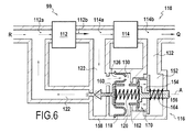
図5および図6を参照すると、ダイアフラム118が損傷した場合にレギュレータ装置がどのように作動するかについての説明が続く。
With reference to FIGS. 5 and 6, a description of how the regulator device operates when the
さまざまな理由のため、ダイアフラム118は劣化することがあり、結果として1つまたは複数の穴を有することがあり、それにより、第1のチャンバは第2のチャンバと流体連通させられる。そのような場合が、図5および図6に示されている。第1のチャンバと第2のチャンバとの間にはいかなる圧力差ももはや存在せず、それにより、第1のばね120は、図5に示されるように、弁部材をその閉位置にさせる。
For a variety of reasons, the
図5から分かるように、ダイアフラムが穿孔されたとき、燃料はダイアフラムを通り、次いでチャネル154を通って第1、第2、および第3のチャンバを流れることができる。
As can be seen from FIG. 5, when the diaphragm is perforated, fuel can flow through the diaphragm and then through the
チャネルは、好ましくは、第2のチャンバの直径より小さい直径を有しており、それにより、チャネル154は、第2のチャンバと第3のチャンバとの間に水頭損失を生じさせるノズルとして作用するようになる。このため、ピストンによって分離されたこれら2つのチャンバ間に圧力差が生じる結果となり、このとき第2のチャンバ内の圧力は、第3のチャンバ内の圧力より高くなる。
The channel preferably has a diameter that is smaller than the diameter of the second chamber so that the
この圧力差が、第2のばね164によってピストン壁上に及ぼされた力より大きい力Fをピストンの面上に発生させるほど十分な場合、ピストンは、第3のチャンバ152に向かって軸方向に移動される。
If this pressure difference is sufficient to generate a force F on the face of the piston that is greater than the force exerted on the piston wall by the
図6から分かるように、摺動形成ピストン150には、この摺動体とケージを機械的に結合するための結合部材170が設けられる。この結合部材170は、ピストン本体の一方の端部から軸Aに向かって径方向に延びるフィンガ172を有する。ピストン本体の内側に延びるケージの端部は、当接面174を有し、この当接面174は、ピストンの軸方向の移動中、ピストン本体のフィンガ172と共働するのに適した1つまたは複数の径方向の突出部によって形成される。
As can be seen from FIG. 6, the sliding forming
図6を参照すると、絞り弁の前後の圧力差によって発生した力が、第2のばね164によって及ぼされた力より大きくなるとき、ピストンが第3のチャンバに向かって軸方向に移動することが理解され得る。この移動中、ピストン本体のフィンガ172は、当接面174と軸方向に接触するようになり、その後、ピストン150は、第3のチャンバに向かってケージおよび弁部材を引っ張る。次いで、弁部材はその開位置を取り、それによって戻り回路122を開く。
Referring to FIG. 6, when the force generated by the pressure difference across the throttle valve is greater than the force exerted by the
したがって、ピストン150およびばね120および164は、弁部材124と共働して、ダイアフラムの損傷にもかかわらず燃料圧力差を調節することができる。
Accordingly,
これは、従来技術の流量計のダイアフラムの破損の場合に一般的に発生する、燃料が注入器に送出される際のレートにおける制御されない増大および絞られた流量と弁114が開かれる開度との間の関係に対する制御されない変更を回避する。
This is an uncontrolled increase in the rate at which fuel is delivered to the injector and the throttled flow rate and the opening at which the
さらに、この例では、ピストンの移動は、チャネル154の第2の端部154bが閉じられることを伴う。これは、ポンプ12と注入器との間の連通のための通路を閉じることにより、エンジンに送出される流量における増大の別の原因を解消するように働く。
Further, in this example, the movement of the piston involves closing the
本発明の範囲を超えることなく、チャネルは、チャネルからの漏出量が許容される限り、ピストンによって決して閉じられないようにして形作られてもよい。 Without exceeding the scope of the present invention, the channel may be shaped such that it is never closed by the piston as long as the amount of leakage from the channel is allowed.
図7および図8に示される変形形態では、チャネル154’は、第1のセクションS1と、第1のセクションS1より大きい第2のセクションS2とを有している。 In the variation shown in FIGS. 7 and 8, the channel 154 'has a first section S1 and a second section S2 that is larger than the first section S1.
図7から分かるように、第1のセクションS1は、調整棒のヘッド156aとピストン内に形成された開口部150cの縁部との間に画定される。
As can be seen from FIG. 7, the first section S1 is defined between the
結果として、ピストンがケージ160に結合されないとき、燃料は、第1のセクションS1を介してチャネル154’を流れ抜ける。
As a result, when the piston is not coupled to the
ここで図8を参照すると、第2のセクションS2は、棒156の本体内に形成された平坦部156bの底部との間に画定されることが理解され得る。
Referring now to FIG. 8, it can be seen that the second section S2 is defined between the bottom of the flat 156b formed in the body of the
平坦部156bがあることにより、第1のセクションS1より大きい第2のセクションS2を得ることができることが明確に分かる。
The presence of the
ピストンが図8のその結合位置にあるとき、ピストン内の開口部150cの縁部は平坦部156bに面しており、それによって、燃料がこのセクションS2を流れ抜けることを可能にする。
When the piston is in its coupling position in FIG. 8, the edge of the opening 0.99 c in the piston faces the
これは、絞り弁114を離れる流量Qに付加された、較正された超過流量Q’を発生させる。
This generates a calibrated excess flow Q 'added to the flow Q leaving the
この超過流量は、たとえば、絞り弁を離れる流量が約300L/hである場合、1時間あたり15リットル(L/h)でもよい。この超過流量は、検出可能でありながらも、絞り弁によって実行される調節の妨げになることを回避するように較正される。 This excess flow rate may be, for example, 15 liters per hour (L / h) when the flow rate leaving the throttle valve is about 300 L / h. This excess flow can be detected but calibrated to avoid obstructing the adjustment performed by the throttle valve.
この超過流量Q’は、絞り弁の調節システムが、その調節関係を変更させたということによって検出される。 This excess flow Q 'is detected by the throttle valve adjustment system changing its adjustment relationship.
絞り弁のみによって送出される流量Qより大きい、注入器の入口の流量Q’’が存在することにより、調節システムは、ダイアフラムが正常に作動している間に送出される流量Qに戻すために絞り弁によって送出される流量を減少させることが必要となる。この相違はすぐに検知可能であり、それによって圧力差検出面が損傷したことをパイロットに知らせることができる。 Due to the presence of the injector inlet flow rate Q ″, which is greater than the flow rate Q delivered by the throttle valve alone, the regulation system will return to the flow rate Q delivered during normal operation of the diaphragm. It is necessary to reduce the flow rate delivered by the throttle valve. This difference can be immediately detected, thereby notifying the pilot that the pressure difference detection surface has been damaged.
Claims (15)
入口(114a)および出口(114b)を有し、ポンプの出口の下流側に配置された絞り弁(114)と、
絞り弁の入口をポンプの入口に接続する戻り回路(122)と、
戻り回路を開閉するように構成された可動式の弁部材と、弁部材(124)に固定され、絞り弁の入口と連通する第1のチャンバ(126)を絞り弁の出口と連通する第2のチャンバ(130)から軸方向に分離する圧力差検出面(118)と、軸方向の推力を戻り回路を閉じるための方向に弁部材上に及ぼすようにして検出面(118)に固定されながら第2のチャンバ(130)内に配置された第1のばね(120)とを備える、圧力レギュレータ装置(116)とを備えた流量計であって、レギュレータ装置(116)が、第2のチャンバ(130)を絞り弁の出口に接続された第3のチャンバ(152)から軸方向に分離するピストン(150)であって、弁部材と共働するように構成された結合部材(170)を含む、ピストン(150)と、ピストンを弁部材から外し共働しない状態に保つための軸方向の推力をピストン上に及ぼしながら第3のチャンバ内に配置された第2のばね(164)とをさらに備え、レギュレータ装置がまた、第2のチャンバ(130)を第3のチャンバ(152)と連通させるチャネル(154)も含むことを特徴とする、燃料流量計(110)。 A fuel flow meter (110) for fuel to be delivered by a pump (112) having an inlet (112a) and an outlet (112b);
A throttle valve (114) having an inlet (114a) and an outlet (114b) and disposed downstream of the outlet of the pump;
A return circuit (122) connecting the inlet of the throttle valve to the inlet of the pump;
A movable valve member configured to open and close the return circuit, and a second chamber that is fixed to the valve member (124) and communicates with the inlet of the throttle valve and communicates with the outlet of the throttle valve. A pressure difference detection surface (118) that is separated from the chamber (130) in the axial direction and an axial thrust force applied to the detection surface (118) so as to exert on the valve member in a direction for closing the return circuit A flow meter comprising a pressure regulator device (116) comprising a first spring (120) disposed in the second chamber (130), wherein the regulator device (116) is in the second chamber. A piston (150) that axially separates (130) from a third chamber (152) connected to the outlet of the throttle valve, the coupling member (170) configured to cooperate with the valve member; Including the piston ( 50), further comprising a second spring (164) disposed in the third chamber while exerting an axial thrust to keep the not cooperate disconnect the piston from the valve member on the piston, the regulator The fuel flow meter (110), wherein the apparatus also includes a channel (154) that communicates the second chamber (130) with the third chamber (152).
Applications Claiming Priority (3)
| Application Number | Priority Date | Filing Date | Title |
|---|---|---|---|
| FR0956540A FR2950390B1 (en) | 2009-09-23 | 2009-09-23 | FUEL DOSER HAVING AN IMPROVED REGULATION DEVICE |
| FR0956540 | 2009-09-23 | ||
| PCT/FR2010/051779 WO2011036363A1 (en) | 2009-09-23 | 2010-08-26 | Fuel flowmeter having an improved control device |
Publications (2)
| Publication Number | Publication Date |
|---|---|
| JP2013505394A JP2013505394A (en) | 2013-02-14 |
| JP5710621B2 true JP5710621B2 (en) | 2015-04-30 |
Family
ID=42173930
Family Applications (1)
| Application Number | Title | Priority Date | Filing Date |
|---|---|---|---|
| JP2012530306A Expired - Fee Related JP5710621B2 (en) | 2009-09-23 | 2010-08-26 | Fuel flow meter with improved regulator device |
Country Status (12)
| Country | Link |
|---|---|
| US (1) | US9239010B2 (en) |
| EP (1) | EP2480774B1 (en) |
| JP (1) | JP5710621B2 (en) |
| KR (1) | KR101656119B1 (en) |
| CN (1) | CN102575585B (en) |
| CA (1) | CA2774320C (en) |
| ES (1) | ES2601833T3 (en) |
| FR (1) | FR2950390B1 (en) |
| IN (1) | IN2012DN02125A (en) |
| PL (1) | PL2480774T3 (en) |
| RU (1) | RU2531838C2 (en) |
| WO (1) | WO2011036363A1 (en) |
Families Citing this family (9)
| Publication number | Priority date | Publication date | Assignee | Title |
|---|---|---|---|---|
| FR2978211B1 (en) * | 2011-07-19 | 2013-08-23 | Snecma | METHOD FOR MONITORING A PRESSURE RELIEF VALVE OF A FUEL INJECTION CIRCUIT FOR TURBOMACHINE |
| CN102943712B (en) * | 2012-11-09 | 2015-01-14 | 沈阳黎明航空发动机(集团)有限责任公司 | Variable-flow fuel adjusting valve |
| CN102980208B (en) * | 2012-11-19 | 2014-12-03 | 哈尔滨工程大学 | Dual-fuel spray nozzle for oil-gas automatic switching in chemical heat return circulation |
| FR3034463B1 (en) | 2015-04-02 | 2017-05-19 | Hispano Suiza Sa | OIL SPRINKLER FOR TURBOMACHINE |
| CN107061021B (en) * | 2016-12-08 | 2019-01-22 | 北京航科发动机控制系统科技有限公司 | A kind of engine mechanical-hydraulic fuel flow submeter regulating device |
| CN108801380B (en) * | 2017-04-28 | 2021-05-04 | 中国航发商用航空发动机有限责任公司 | Fuel gauge oil return valve and fuel gauge |
| CN107100744B (en) * | 2017-05-31 | 2018-11-09 | 大连理工大学 | A kind of aero-engine fuel metering system improvement strategy and its controller design method |
| CN109654268B (en) * | 2017-10-11 | 2020-08-11 | 中国航发西安动力控制科技有限公司 | Differential pressure mechanism |
| GB202113063D0 (en) * | 2021-09-14 | 2021-10-27 | Rolls Royce Plc | Fluid pump |
Family Cites Families (19)
| Publication number | Priority date | Publication date | Assignee | Title |
|---|---|---|---|---|
| GB585032A (en) * | 1943-12-10 | 1947-01-29 | Robert James Eldred | Improvements in governors for internal combustion turbines |
| US2958376A (en) * | 1956-03-07 | 1960-11-01 | Bendix Corp | Starting control for internal combustion engines |
| US2917067A (en) * | 1956-09-21 | 1959-12-15 | United Aircraft Corp | Temperature compensated regulator |
| US3128783A (en) * | 1957-02-11 | 1964-04-14 | Holley Carburetor Co | Bypass valve with limited reset |
| US3005464A (en) * | 1959-08-21 | 1961-10-24 | Chandler Evans Corp | Metering head control devices |
| JPS5540783B2 (en) * | 1974-09-11 | 1980-10-20 | ||
| FR2339203A1 (en) | 1976-01-20 | 1977-08-19 | Bronzavia Sa | DEVICE FOR ADJUSTING THE DIFFERENTIAL PRESSURE BETWEEN TWO DIFFERENT PRESSURE POINTS OF A FLUID CIRCUIT |
| JPS5324629A (en) * | 1976-08-19 | 1978-03-07 | Tokico Ltd | Pressure regulator |
| US4716723A (en) * | 1986-09-05 | 1988-01-05 | Woodward Governor Company | Fuel controls for gas turbine engines |
| US4805658A (en) | 1987-04-24 | 1989-02-21 | United Technologies Corporation | Variable pressure regulating valve |
| US5078173A (en) * | 1991-06-14 | 1992-01-07 | General Electric Company | Droop compensated bypass valve |
| RU2029122C1 (en) * | 1992-08-12 | 1995-02-20 | Научно-производственное предприятие "Эга" | Device for automatic supply of fuel into combustion chamber of gas-turbine engine |
| US5327720A (en) * | 1993-05-03 | 1994-07-12 | Allied-Signal Inc. | Differential pressure regulator valve |
| US5433237A (en) * | 1994-07-11 | 1995-07-18 | Woodward Governor Company | Dedrooped bypass valve |
| FR2729183A1 (en) * | 1995-01-11 | 1996-07-12 | Snecma | PRESSURIZED DIFFERENCE DETECTOR WITH REDUCED STRENGTHS |
| US6381946B1 (en) * | 2000-05-22 | 2002-05-07 | Woodward Governor Company | Two stage fuel metering system for gas turbine |
| RU2193097C2 (en) * | 2000-08-21 | 2002-11-20 | Харьковское Агрегатное Конструкторское Бюро | Device for automatic control fuel delivery into gas turbine engine |
| JP4644982B2 (en) * | 2001-07-09 | 2011-03-09 | 株式会社Ihi | Fuel flow control device |
| FR2874055B1 (en) * | 2004-08-04 | 2006-11-24 | Hispano Suiza Sa | DOSAGE CONTROL WITH TWO DISSOCATED REGULATION LAWS FOR EMERGENCY REGULATOR |
-
2009
- 2009-09-23 FR FR0956540A patent/FR2950390B1/en not_active Expired - Fee Related
-
2010
- 2010-08-26 WO PCT/FR2010/051779 patent/WO2011036363A1/en active Application Filing
- 2010-08-26 KR KR1020127006579A patent/KR101656119B1/en active IP Right Grant
- 2010-08-26 CA CA2774320A patent/CA2774320C/en active Active
- 2010-08-26 US US13/496,216 patent/US9239010B2/en active Active
- 2010-08-26 PL PL10763755T patent/PL2480774T3/en unknown
- 2010-08-26 RU RU2012116066/06A patent/RU2531838C2/en not_active IP Right Cessation
- 2010-08-26 IN IN2125DEN2012 patent/IN2012DN02125A/en unknown
- 2010-08-26 JP JP2012530306A patent/JP5710621B2/en not_active Expired - Fee Related
- 2010-08-26 CN CN201080042804.8A patent/CN102575585B/en active Active
- 2010-08-26 EP EP10763755.5A patent/EP2480774B1/en active Active
- 2010-08-26 ES ES10763755.5T patent/ES2601833T3/en active Active
Also Published As
| Publication number | Publication date |
|---|---|
| ES2601833T3 (en) | 2017-02-16 |
| IN2012DN02125A (en) | 2015-08-21 |
| EP2480774B1 (en) | 2016-10-05 |
| CA2774320A1 (en) | 2011-03-31 |
| CN102575585B (en) | 2015-02-25 |
| WO2011036363A1 (en) | 2011-03-31 |
| US20120174587A1 (en) | 2012-07-12 |
| FR2950390A1 (en) | 2011-03-25 |
| RU2531838C2 (en) | 2014-10-27 |
| KR101656119B1 (en) | 2016-09-08 |
| RU2012116066A (en) | 2013-10-27 |
| KR20120083329A (en) | 2012-07-25 |
| US9239010B2 (en) | 2016-01-19 |
| PL2480774T3 (en) | 2017-02-28 |
| JP2013505394A (en) | 2013-02-14 |
| FR2950390B1 (en) | 2011-10-21 |
| EP2480774A1 (en) | 2012-08-01 |
| CA2774320C (en) | 2017-01-03 |
| CN102575585A (en) | 2012-07-11 |
Similar Documents
| Publication | Publication Date | Title |
|---|---|---|
| JP5710621B2 (en) | Fuel flow meter with improved regulator device | |
| US7966994B2 (en) | System for metering a fuel supply | |
| JP2006017126A (en) | Fuel injector of internal combustion engine | |
| US8720482B2 (en) | Fuel system | |
| EP3179078B1 (en) | Fuel control system | |
| CN105102803B (en) | System and method for adjusting the pressure in fuel delivery system | |
| US6695005B2 (en) | Pressure regulating valve | |
| CN103375452B (en) | Servo minimum pressure valve assembly, fuel-control unit and installation method thereof | |
| JP5537108B2 (en) | Check valve and steam supply system using the same | |
| KR950012266B1 (en) | Flow rate control valve device | |
| JP2020200973A (en) | Heating power control device | |
| CN107003683B (en) | Gas pressure adjusting device | |
| JP5547609B2 (en) | Pressure regulator | |
| JP4586099B1 (en) | Constant flow control device | |
| JP2011017440A (en) | Constant flow rate control device | |
| JP4872946B2 (en) | Solenoid spool valve | |
| US11187339B2 (en) | Pressure relief valve | |
| WO2012063283A1 (en) | Constant flow control device | |
| JP4919896B2 (en) | Pressure regulating valve | |
| RU2136036C1 (en) | Direct-acting temperature controller | |
| JP2005233219A (en) | Servo piston mechanism and flow regulating valve | |
| KR20110068080A (en) | Valve for controling overflow and hydraulic system including the same | |
| US20140130915A1 (en) | Low hysteresis fluid metering valve | |
| ITTO20130793A1 (en) | PRESSURE REDUCER UNIT EQUIPPED WITH A SAFETY DEVICE TO AUTOMATICALLY ADJUST THE CALIBRATION OF A VALVE, FOR A FUEL GAS DISTRIBUTION NETWORK | |
| JP2006313456A (en) | Pressure regulator |
Legal Events
| Date | Code | Title | Description |
|---|---|---|---|
| A621 | Written request for application examination |
Free format text: JAPANESE INTERMEDIATE CODE: A621 Effective date: 20130802 |
|
| A977 | Report on retrieval |
Free format text: JAPANESE INTERMEDIATE CODE: A971007 Effective date: 20140325 |
|
| A131 | Notification of reasons for refusal |
Free format text: JAPANESE INTERMEDIATE CODE: A131 Effective date: 20140401 |
|
| A521 | Request for written amendment filed |
Free format text: JAPANESE INTERMEDIATE CODE: A523 Effective date: 20140701 |
|
| TRDD | Decision of grant or rejection written | ||
| A01 | Written decision to grant a patent or to grant a registration (utility model) |
Free format text: JAPANESE INTERMEDIATE CODE: A01 Effective date: 20150203 |
|
| A61 | First payment of annual fees (during grant procedure) |
Free format text: JAPANESE INTERMEDIATE CODE: A61 Effective date: 20150304 |
|
| R150 | Certificate of patent or registration of utility model |
Ref document number: 5710621 Country of ref document: JP Free format text: JAPANESE INTERMEDIATE CODE: R150 |
|
| R250 | Receipt of annual fees |
Free format text: JAPANESE INTERMEDIATE CODE: R250 |
|
| R250 | Receipt of annual fees |
Free format text: JAPANESE INTERMEDIATE CODE: R250 |
|
| LAPS | Cancellation because of no payment of annual fees |