JP5710418B2 - Packet relay apparatus and method - Google Patents
Packet relay apparatus and method Download PDFInfo
- Publication number
- JP5710418B2 JP5710418B2 JP2011172611A JP2011172611A JP5710418B2 JP 5710418 B2 JP5710418 B2 JP 5710418B2 JP 2011172611 A JP2011172611 A JP 2011172611A JP 2011172611 A JP2011172611 A JP 2011172611A JP 5710418 B2 JP5710418 B2 JP 5710418B2
- Authority
- JP
- Japan
- Prior art keywords
- packet
- flow
- congestion state
- congestion
- relay device
- Prior art date
- Legal status (The legal status is an assumption and is not a legal conclusion. Google has not performed a legal analysis and makes no representation as to the accuracy of the status listed.)
- Active
Links
- 238000000034 method Methods 0.000 title claims description 47
- 239000000872 buffer Substances 0.000 claims description 209
- 230000005540 biological transmission Effects 0.000 claims description 164
- 238000012544 monitoring process Methods 0.000 claims description 103
- 230000004044 response Effects 0.000 claims description 34
- 230000008569 process Effects 0.000 claims description 31
- 230000009471 action Effects 0.000 description 110
- 238000011144 upstream manufacturing Methods 0.000 description 65
- 238000001514 detection method Methods 0.000 description 64
- 238000012545 processing Methods 0.000 description 49
- 238000004891 communication Methods 0.000 description 36
- 230000006870 function Effects 0.000 description 18
- 238000009825 accumulation Methods 0.000 description 14
- 238000010586 diagram Methods 0.000 description 13
- 238000004364 calculation method Methods 0.000 description 10
- 101000763314 Homo sapiens Thrombomodulin Proteins 0.000 description 8
- 102100026966 Thrombomodulin Human genes 0.000 description 8
- XLYOFNOQVPJJNP-UHFFFAOYSA-N water Substances O XLYOFNOQVPJJNP-UHFFFAOYSA-N 0.000 description 8
- 101000821827 Homo sapiens Sodium/nucleoside cotransporter 2 Proteins 0.000 description 4
- 102100021541 Sodium/nucleoside cotransporter 2 Human genes 0.000 description 4
- 230000004913 activation Effects 0.000 description 4
- 230000003139 buffering effect Effects 0.000 description 4
- 230000003111 delayed effect Effects 0.000 description 4
- 230000000694 effects Effects 0.000 description 4
- RTZKZFJDLAIYFH-UHFFFAOYSA-N Diethyl ether Chemical compound CCOCC RTZKZFJDLAIYFH-UHFFFAOYSA-N 0.000 description 2
- 238000012217 deletion Methods 0.000 description 2
- 230000037430 deletion Effects 0.000 description 2
- 238000005516 engineering process Methods 0.000 description 2
- 238000012986 modification Methods 0.000 description 2
- 230000004048 modification Effects 0.000 description 2
- 239000008186 active pharmaceutical agent Substances 0.000 description 1
- 230000015556 catabolic process Effects 0.000 description 1
- 230000003247 decreasing effect Effects 0.000 description 1
- 238000006731 degradation reaction Methods 0.000 description 1
- 230000006866 deterioration Effects 0.000 description 1
- 238000005111 flow chemistry technique Methods 0.000 description 1
- 230000009191 jumping Effects 0.000 description 1
- 239000007787 solid Substances 0.000 description 1
- 238000012546 transfer Methods 0.000 description 1
- 230000001960 triggered effect Effects 0.000 description 1
Images


Classifications
-
- H—ELECTRICITY
- H04—ELECTRIC COMMUNICATION TECHNIQUE
- H04L—TRANSMISSION OF DIGITAL INFORMATION, e.g. TELEGRAPHIC COMMUNICATION
- H04L47/00—Traffic control in data switching networks
- H04L47/10—Flow control; Congestion control
- H04L47/35—Flow control; Congestion control by embedding flow control information in regular packets, e.g. piggybacking
-
- H—ELECTRICITY
- H04—ELECTRIC COMMUNICATION TECHNIQUE
- H04L—TRANSMISSION OF DIGITAL INFORMATION, e.g. TELEGRAPHIC COMMUNICATION
- H04L47/00—Traffic control in data switching networks
- H04L47/10—Flow control; Congestion control
- H04L47/17—Interaction among intermediate nodes, e.g. hop by hop
-
- H—ELECTRICITY
- H04—ELECTRIC COMMUNICATION TECHNIQUE
- H04L—TRANSMISSION OF DIGITAL INFORMATION, e.g. TELEGRAPHIC COMMUNICATION
- H04L47/00—Traffic control in data switching networks
- H04L47/10—Flow control; Congestion control
- H04L47/12—Avoiding congestion; Recovering from congestion
-
- H—ELECTRICITY
- H04—ELECTRIC COMMUNICATION TECHNIQUE
- H04L—TRANSMISSION OF DIGITAL INFORMATION, e.g. TELEGRAPHIC COMMUNICATION
- H04L47/00—Traffic control in data switching networks
- H04L47/10—Flow control; Congestion control
- H04L47/31—Flow control; Congestion control by tagging of packets, e.g. using discard eligibility [DE] bits
-
- H—ELECTRICITY
- H04—ELECTRIC COMMUNICATION TECHNIQUE
- H04L—TRANSMISSION OF DIGITAL INFORMATION, e.g. TELEGRAPHIC COMMUNICATION
- H04L47/00—Traffic control in data switching networks
- H04L47/10—Flow control; Congestion control
- H04L47/40—Flow control; Congestion control using split connections
Description
本発明は、ネットワークにおけるパケット中継装置、特に輻輳通知機能を備える装置の帯域監視技術に関する。 The present invention relates to a bandwidth monitoring technique for a packet relay device in a network, particularly a device having a congestion notification function.
輻輳通知技術の一つであるECN(Explicit Congestion Notification)が、LINUXやWINDOWS(登録商標)等のOS(Operating System)にオプション機能として実装され、またIETF(Internet Engineering Task Force)でも盛んに議論されるなど、脚光を浴びている。 ECN (Explicit Congestion Notification), one of the congestion notification technologies, is implemented as an optional function in OS (Operating System) such as LINUX and WINDOWS (registered trademark), and is also actively discussed in IETF (Internet Engineering Task Force) And so on.
ECNとは、ネットワークを構成するルータ/スイッチ等のパケット中継装置において輻輳が発生した場合に、送信端末から送信されたデータパケットに対しルータ/スイッチ自身で輻輳情報を明示的にマーキングして受信端末に送信することで、受信端末に輻輳情報を通知する輻輳通知技術である(特許文献1参照)。 ECN is a receiving terminal in which congestion information is explicitly marked on the data packet transmitted from the transmitting terminal by the router / switch itself when congestion occurs in a packet relay device such as a router / switch constituting the network. This is a congestion notification technique for notifying the receiving terminal of congestion information by transmitting to (see Patent Document 1).
従来のTCP(Transmission Control Protocol)が備える輻輳回避機能では、輻輳発生を明示的に送受信端末に通知する手段がなかった。そのため、ネットワークにおいてパケット廃棄が生じたことをタイムアウトや重複ACK受信により送信端末にて検出した場合に、輻輳の発生を送信端末が自律的に判断する仕組みとなっていた。輻輳が発生したと判断された場合には、送信端末が送信帯域を抑制することで輻輳回避を実現する。 In the congestion avoidance function provided in the conventional Transmission Control Protocol (TCP), there is no means for explicitly notifying the transmission / reception terminal of the occurrence of congestion. Therefore, the transmission terminal autonomously determines the occurrence of congestion when the transmission terminal detects that packet discard has occurred in the network due to timeout or duplicate ACK reception. When it is determined that congestion has occurred, congestion avoidance is realized by the transmission terminal suppressing the transmission bandwidth.
パケットが廃棄された場合には、廃棄されたパケットのデータを補完しなければ受信端末でのアプリケーション処理を正常に実行できないため、送信端末のTCPは廃棄されたパケットを再送する機能を備えている。廃棄されたパケットは再送されるが、再送パケットが受信端末に到着するタイミングは、パケット廃棄が生じなかった場合に本来パケットが到着したはずのタイミングよりも遅れてしまう。そのため、再送パケットを受信して、パケットとして分割されたデータを再構成してアプリケーション処理できるようになるタイミングが遅れてしまい、通信品質が低下してしまう問題があった。 When a packet is discarded, application processing at the receiving terminal cannot be executed normally unless the data of the discarded packet is complemented. Therefore, the TCP of the transmitting terminal has a function of retransmitting the discarded packet. . Although the discarded packet is retransmitted, the timing at which the retransmitted packet arrives at the receiving terminal is delayed from the timing at which the packet should have originally arrived when no packet discard has occurred. For this reason, there is a problem that the timing at which a retransmission packet is received, the data divided as a packet is reconstructed and application processing can be delayed, and the communication quality deteriorates.
ECNでは、ルータ/スイッチのようなパケット中継装置において輻輳を検出すると、データパケットのIPヘッダのTOSフィールドの下位2ビットにて定義されるECNフィールドを、輻輳検出済の意味をもつCE(Congestion Experienced)の値にルータ/スイッチが書き換えるECNマーキングを実施して、可能な限りパケット廃棄することなく中継する。 In ECN, when congestion is detected in a packet relay device such as a router / switch, the ECN field defined by the lower 2 bits of the TOS field in the IP header of the data packet is changed to CE (Congestion Experienced ECN marking that router / switch rewrites to the value of), and relays without discarding packets as much as possible.
CEパケットを受信した受信端末は、それ以降送信端末に返信するACK(Acknowledge)パケットにおいて、輻輳検出したことを送信端末に通知するためECN向けに拡張されたTCP制御フラグのECE(ECN Echo)フラグを’1’にセットする。送信端末は、ECEフラグがセットされたACKパケットを受信すると、ネットワークが輻輳状態にあるものと判断し、従来のECNを備えないTCPがもつ輻輳回避機能に基づいて送信帯域を抑制することで、輻輳回避する。輻輳回避の処理を実行すると、送信端末は送信パケットにTCP制御フラグのCWR(Congestion Window Reduced)フラグをセットする。CWRフラグは、送信端末にて輻輳回避の処理を行った後に、受信端末が返信するACKパケットのECEフラグのセットを停止させるためECN向けに拡張されたTCP制御フラグである。受信端末はCWRフラグがセットされたパケットを受信すると、ACKパケットに対するECEフラグのセットを停止する。 The receiving terminal that has received the CE packet then uses the ECE (ECN Echo) flag, which is an extended TCP control flag for ECN to notify the transmitting terminal that congestion has been detected in an ACK (Acknowledge) packet sent back to the transmitting terminal. Is set to '1'. When the transmitting terminal receives the ACK packet in which the ECE flag is set, the transmitting terminal determines that the network is in a congested state, and suppresses the transmission band based on the congestion avoidance function of the TCP that does not have the conventional ECN, Avoid congestion. When the congestion avoiding process is executed, the transmitting terminal sets a TCP control flag CWR (Congestion Window Reduced) flag in the transmission packet. The CWR flag is a TCP control flag extended for ECN in order to stop the setting of the ECE flag of the ACK packet returned by the receiving terminal after performing processing for avoiding congestion at the transmitting terminal. When the receiving terminal receives the packet in which the CWR flag is set, the receiving terminal stops setting the ECE flag for the ACK packet.
このようにECNを用いることで、ルータ/スイッチにおいて輻輳を検出した際のパケット廃棄を可能な限り抑止し、パケットを中継しつつ輻輳発生を明示的に送受信端末に通知して送信帯域の抑制を促すことが可能となり、パケット廃棄やこれに伴うパケット再送による通信品質の低下を抑制できる。 By using ECN in this way, packet discarding when congestion is detected in the router / switch is suppressed as much as possible, and congestion is explicitly notified to the transmitting and receiving terminals while relaying packets, thereby suppressing transmission bandwidth. This makes it possible to suppress communication quality degradation due to packet discard and accompanying packet retransmission.
また、従来のパケット廃棄により輻輳の発生を判断する輻輳回避技術では、ビットエラー等の障害によるパケット廃棄を、ネットワークの輻輳によるパケット廃棄と区別することができないため、輻輳とは無関係のビットエラー障害に対しても輻輳回避の処理がなされてしまい、送信帯域の不要な低下を招いてしまう問題があった。しかしECNでは、送受信端末に対して輻輳発生が明示的に通知されるので、ビットエラー障害とネットワークの輻輳を明確に区別してネットワークの輻輳の場合のみ輻輳回避することが可能となり、送信帯域の不要な低下を防止できるようになる。 Also, the conventional congestion avoidance technology that determines the occurrence of congestion by discarding packets cannot distinguish packet discard due to failures such as bit errors from packet discard due to network congestion, so bit error failures that are unrelated to congestion However, there is a problem that processing for avoiding congestion is performed, and the transmission bandwidth is unnecessarily reduced. However, in ECN, the occurrence of congestion is explicitly notified to the sending and receiving terminals, so it is possible to clearly distinguish between bit error failure and network congestion and avoid congestion only in the case of network congestion, and no transmission bandwidth is required. Can be prevented.
TCPでは、受信端末がデータパケットを受信すると、受信端末はこれに対するACKパケットを送信端末に送信する。送信端末はACKパケットを受信すると送信帯域を増大させるが、ECNに基づいてECEフラグをセットされた輻輳通知用のACKパケットを受信すると、輻輳回避するため送信帯域を減少させる帯域制御を行う。 In TCP, when a receiving terminal receives a data packet, the receiving terminal transmits an ACK packet for the data packet to the transmitting terminal. When the transmitting terminal receives the ACK packet, it increases the transmission band. However, when it receives the congestion notification ACK packet in which the ECE flag is set based on the ECN, it performs band control to decrease the transmission band in order to avoid congestion.
従来のECNでは、ルータ/スイッチ等のパケット中継装置において輻輳が発生すると、パケット中継装置→受信端末→パケット中継装置→送信端末の経路で輻輳情報を通知する。そのため、パケット中継装置と受信端末間の遅延が増大すると輻輳通知が遅れてしまうこととなる。輻輳通知がなされるまでの間、ネットワークは輻輳状態にあるにも関わらず送信端末は受信したACKパケットの分だけ送信帯域を増大させるので、輻輳状態は更に悪化してしまう。その結果、廃棄パケットが増加し、廃棄パケットを補完するための再送パケットも増加するので、実効帯域の低下、実効遅延の増大を招き、通信品質が低下してしまうという課題がある。 In the conventional ECN, when congestion occurs in a packet relay device such as a router / switch, congestion information is notified through a route of packet relay device → receiving terminal → packet relay device → transmitting terminal. Therefore, if the delay between the packet relay device and the receiving terminal increases, the congestion notification will be delayed. Until the congestion notification is made, the transmission terminal increases the transmission bandwidth by the received ACK packet even though the network is in a congestion state, and the congestion state is further deteriorated. As a result, the number of discarded packets increases, and the number of retransmitted packets for complementing the discarded packets also increases. This causes a problem that the effective bandwidth is decreased and the effective delay is increased, leading to a decrease in communication quality.
本発明の目的は、上記の課題を解決し、パケット中継装置から受信端末の遅延が増大した場合にも、輻輳通知の遅延を防止することが可能なパケット中継装置、及び方法を提供することにある。 An object of the present invention is to provide a packet relay apparatus and method capable of solving the above-described problems and preventing a congestion notification delay even when the delay of the receiving terminal from the packet relay apparatus increases. is there.
上記の目的を達成するため、本発明においては、パケットを中継するパケット中継装置であって、複数の入力回線と出力回線と、入力回線から受信したパケットを検索するパケット検索部を備え、パケット検索部は、入力回線から受信したパケットの情報により識別されるパケットの集合が構成されるフローを検出し、検出したフローが輻輳状態にあると判定すると、それ以降に受信する当該フローに対する応答パケットのヘッダの内、輻輳状態を示すフィールドを輻輳状態にあることを示す値に書き換えるパケット中継装置を提供する。 In order to achieve the above object, the present invention provides a packet relay apparatus for relaying a packet, comprising a plurality of input lines, an output line, and a packet search unit for searching for a packet received from the input line. When the unit detects a flow comprising a set of packets identified by packet information received from the input line and determines that the detected flow is in a congested state, a response packet for the flow received thereafter Provided is a packet relay device that rewrites a field indicating a congestion state in a header to a value indicating that it is in a congestion state.
また、上記の目的を達成するため、本発明においては、複数の入力回線と出力回線を備えたパケット中継装置のパケット中継方法であって、入力回線から受信したパケットの情報により識別されるパケットの集合が構成されるフローを検出し、検出したフローが輻輳状態にあると判定すると、それ以降に受信する当該フローに対する応答パケットのヘッダの内、輻輳状態を示すフィールドを輻輳状態にあることを示す値に書き換えるパケット中継方法を提供する。 In order to achieve the above object, according to the present invention, there is provided a packet relay method for a packet relay apparatus having a plurality of input lines and output lines, and a packet relay method for identifying a packet identified by packet information received from an input line. When a flow that constitutes a set is detected and it is determined that the detected flow is in a congested state, the field indicating the congested state is indicated in the congested state in the header of the response packet for the flow that is received thereafter. A packet relay method for rewriting a value is provided.
本発明によれば、ルータ/スイッチから受信端末の遅延が増大した場合にも、輻輳通知の遅延を防止する。 According to the present invention, even when the delay of the receiving terminal from the router / switch increases, the congestion notification delay is prevented.
また、本発明を備えていないパケット中継装置で判定された輻輳に対しても、輻輳通知の遅延を防止する。 In addition, a congestion notification delay is prevented even for congestion determined by a packet relay apparatus that does not include the present invention.
更に、受信端末が輻輳通知機能を備えていない場合にも、輻輳通知システムを実現する。 Furthermore, a congestion notification system is realized even when the receiving terminal does not have a congestion notification function.
以下に、本発明を実施するための形態を図面に従い説明する。それに先立ち、本発明の輻輳通知機能を備えるパケット中継装置の基本構成について説明する。本発明のパケット中継装置の基本構成では、複数の入力回線と出力回線を備え、入力回線から受信したパケットの入力物理回線番号、または入力論理回線番号、またはパケットヘッダ情報のうち、少なくとも一つ以上の情報により識別されるパケットの集合から構成されるフローを検出し、フローが輻輳状態にあると判定すると、それ以降に受信した当該フローに対する応答パケットのパケットヘッダのうち、ネットワークの輻輳状態を示すフィールドを輻輳状態にあることを示す値に書き換える。 Hereinafter, embodiments for carrying out the present invention will be described with reference to the drawings. Prior to that, a basic configuration of a packet relay apparatus having the congestion notification function of the present invention will be described. In the basic configuration of the packet relay apparatus of the present invention, a plurality of input lines and output lines are provided, and at least one of the input physical line number, the input logical line number, or the packet header information of the packet received from the input line If a flow composed of a set of packets identified by the above information is detected and it is determined that the flow is in a congestion state, it indicates the congestion state of the network in the packet header of the response packet for the flow received thereafter. Rewrite the field with a value indicating that it is in a congested state.
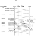
図1を用いて、本発明のパケット中継装置の基本構成の処理と効果を説明する。送信端末1と受信端末3間はECN(Explicit Congestion Notification)を用いて輻輳通知しているものとする。送信端末1から送信されたデータパケット14をパケット中継装置2が受信した際に、データパケット14が属するフローが輻輳状態にあると判定した場合、パケット中継装置2は、これ以降、受信端末3から送信されたTCPの応答パケット(ACK)16を受信すると、このACKパケット16のECE(ECN Echo)フラグを0から1に書き換えて、ACKパケット(ECE)17として送信端末1に送信する。これにより、パケット中継装置2から送信端末1への経路で輻輳通知できる。この輻輳通知を受け、送信端末1は、ウインドウサイズを縮小し、その旨を通知するCWR(Condestion Window Reduce)フラグをセットしてデータ(CWR)18を送信する。
The processing and effects of the basic configuration of the packet relay apparatus according to the present invention will be described with reference to FIG. It is assumed that congestion notification is sent between the sending
一方、以上説明した本発明の基本構成を用いない場合のパケット中継装置の処理の流れの場合、送信端末1から送信されたデータパケット14をパケット中継装置2が受信した際に、当該データパケット14が属するフローが輻輳状態にあると判定すると、パケット中継装置2はデータパケット14のECNフィールドを11(Congestion Experienced:CE)に書き換えて、データパケット(CE)15として受信端末3に送信する。受信端末3はデータパケット(CE)15を受信すると、ECNフィールドが11(CE)という輻輳発生を示す値にあるので、これ以降送信するACKパケットのECE(ECN Echo)フラグを1として、ACK(ECE)を送信する。パケット中継装置2はACK(ECE)を受信するとそのままACK(ECE)17として送信端末1に送信する。従って、パケット中継装置2から受信端末3、受信端末3からパケット中継装置2、パケット中継装置2から送信端末1の経路で輻輳通知することとなる。
On the other hand, in the case of the processing flow of the packet relay apparatus when the basic configuration of the present invention described above is not used, when the
以上より明らかなように、本発明のパケット中継装置の基本構成によれば、パケット中継装置2から受信端末3、受信端末3からパケット中継装置2の分だけ輻輳通知の経路を省いて短縮することができる。その結果、パケット中継装置2と受信端末3間の遅延が増大しても、輻輳通知は遅れないこととなり、通信品質の低下を防止できるという効果を得ることとなる。
As is clear from the above, according to the basic configuration of the packet relay apparatus of the present invention, the congestion notification path is shortened by the amount from the
図2〜図24を用いて、第1の実施例のパケット中継装置を説明する。以下においては、、TCP/IPパケットかつ、輻輳通知にはECNを用いるものとして説明するが、DCCP(Data Congestion Control Protocol)、SCTP(Stream Control Transmission Protocol)等の他のトランスポートプロトコルのパケット、他の輻輳通知のプロトコルであっても構わない。 The packet relay apparatus according to the first embodiment will be described with reference to FIGS. In the following description, it is assumed that ECN is used for TCP / IP packets and congestion notification, but other transport protocol packets such as DCCP (Data Congestion Control Protocol) and SCTP (Stream Control Transmission Protocol), etc. The congestion notification protocol may be used.
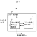
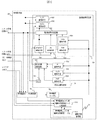
まず、図2に本実施例のパケット中継装置の一構成例を示す。パケット中継装置2には、パケット入力用の入力回線20と、パケット出力用の出力回線30が接続されている。また、パケット中継装置2の内部には、パケットの受信処理を行うパケット受信回路21と、入力パケットに対するパケット検索部22と、パケット検索部22の経路検索部23で宛先IPアドレスから経路検索を行って判定された出力回線番号に基づきパケットをスイッチングするパケット中継処理手段26と、入力パケットに対するパケット検索部27と、パケットを読み出してパケットの送信処理を行うパケット送信回路28を備える。パケット検索部22内の経路検索部23で宛先IPアドレスから経路検索により出力回線番号を判定する検索方式は本実施例の構成では特定しないが、経路検索方式の一例は、例えば特許文献3に開示されている。
First, FIG. 2 shows a configuration example of the packet relay apparatus of this embodiment. The
なお、パケット検索部22とパケット検索部27は、受信側と送信側が異なる他は、フロー検出部24と帯域監視部25などに関し同様の構成となっている。本明細書において、パケット検索部と称する場合、パケット検索部22、パケット検索部27の何れか一方または両方を意味している。また、パケット受信回路21とパケット送信回路28は、パケットヘッダのECNフィールドとECEフィールドの書き換え機能を備えている。
The
図2の構成において、入力回線20と出力回線30がそれぞれ1回線ずつ記載されているが、パケット中継装置2は、複数の入力回線20、複数の出力回線30を備える。パケット受信回路21とこれに接続されたパケット検索部22は、複数の入力回線20を収容することができる。また、パケット受信回路21とこれに接続されたパケット検索部22を複数備えて、それぞれが互いに異なる複数の入力回線20を収容する構成としても良い。同様にパケット送信回路28とこれに接続されたパケット検索部27は、複数の入力回線を収容することができる。また、パケット送信回路28とこれに接続されたパケット検索部27を複数備えて、それぞれが互いに異なる複数の出力回線30を収容する構成としても良い。また、パケット中継装置2には管理端末19が接続されており、レジスタを経由してパケット中継装置2の管理と各種設定を行う。
In the configuration of FIG. 2, one
パケット中継装置2は、パケット受信回路21に接続される入力回線20からパケットを受信する。送信端末1から送信されたパケットは入力回線20を経由してパケット受信回路21に入力される。
The
図3に本実施例のパケット受信回路21の一構成例を示す。パケット受信回路21はパケット受信バッファ制御部210とパケット受信バッファ211とバッファ蓄積パケット数管理部212から構成される。パケット受信バッファ制御部210は、パケット受信バッファ211に対する読み出し制御と書き込み制御、バッファ面に対する上書きを許可する開放制御を行う。バッファ蓄積パケット数管理部212は、パケット受信パケット受信バッファ211に蓄積されているパケット数を計数して管理する。
FIG. 3 shows a configuration example of the
図4Aにパケット受信バッファ211の内部構成の一例を示す。パケット受信バッファ211は複数のバッファ面2111〜2113から構成されている。各バッファ面には、図4Bに示すパケットのパケットヘッダ情報1000として、L2ヘッダ部102として宛先MACアドレス1020、送信元MACアドレス1021、イーサタイプ1022、VLAN(Virtual Local Area Network)ID1023、L3ヘッダ部103としてIPバージョン1030、TOS(Type of Service)1031、L4プロトコル1032、送信元IPアドレス1033、宛先IPアドレス1034、L4ヘッダ部104として送信元ポート番号1040、宛先ポート番号1041、TCPフラグ1042、そしてパケット受信回路1にて付加される内部ヘッダ101として入力回線番号1010とパケットのバイト長を示すLEN1011が書き込みされる。なお、図4Aに示す、パケットヘッダ情報1000の構成は一例であり、本実施例の構成を限定するものではない。
FIG. 4A shows an example of the internal configuration of the
次に、図5に示すように、TOS 1031は、ネットワークにおける転送の優先度を示すDSCP(Differentiated Services Code Point)フィールド10310と、ECNによる輻輳通知に用いられるECNフィールド10311から構成される。なお、DSCPの定義に関しては非特許文献1の第3章に、DSCPが適用されるQOSアーキテクチャのDiffservモデルに関しては非特許文献2の第2章に説明されている。ECNフィールド10311は、”01”または”10”の値のときにECNをサポート(ECN:ECN−Capable−Transport)していること、”11”のときにパケットが輻輳を経験したこと(CE:Congestion Experienced)を示す。ECNをサポートしている送信端末はECNフィールドを”01”または”10”に設定したパケットを送信し、パケット中継装置2にて輻輳が発生していると判断された場合、このフィールドはパケット中継装置2により”11”に書き換えられる。
Next, as shown in FIG. 5, the
図6に示すように、TCPフラグ1042は、既存のフラグURG10422、ACK10423、PSH10424、RST10425、SYN10426、FIN10427に対し、ECNの拡張によりCWR10420、ECE10421が追加されている。
As shown in FIG. 6, in the
図2、図3に示した本実施例のパケット受信回路21は、入力回線20からパケットが入力されると、パケットが入力された順序に従って、パケット受信バッファ制御部210により、パケット受信バッファ211のバッファ面2111からバッファ面2113の順に、入力パケットのパケットヘッダ情報1000を書き込む。なお、バッファ蓄積パケット数管理部212にて管理するバッファ蓄積パケット数が全バッファ面数に相当するn個に達し、全てのバッファ面にn個のパケットヘッダ情報1000が書き込みされてしまうと、最初に書き込みされたバッファ面2111が開放されるまでの間、パケット受信回路21はパケットの受信を停止し、停止中に入力回線20から新たにパケットが入力した場合はこれを廃棄する。
2 and FIG. 3, when a packet is input from the
最初に書き込みされたバッファ面2111に書き込みされたパケットが、パケット検索部22での処理を完了してパケット中継処理手段26に出力され、そのパケットヘッダ情報1000をバッファ面2111に蓄積しておく必要がなくなると、パケット受信バッファ制御部210はバッファ面2111を開放する。そして、これ以降、入力回線20から新たにパケットが入力した場合は、パケット受信バッファ制御部210が、開放されたバッファ面2111に、当該パケットのパケットヘッダ情報1000を書き込みする。
The packet written to the buffer surface 2111 that was written first must be processed by the
そして、パケット検索部22がパケットを受付可能なタイミングになると、パケット受信バッファ211に蓄積したパケットヘッダ情報1000を送信する。また、パケット検索部22での処理が完了してパケットをパケット中継処理手段26に送信するまでの間は、パケットヘッダ情報1000を一時的にパケット受信バッファ211に蓄積したままとしておく。以降、パケット中継処理手段26にパケットを新たに出力すると、その都度バッファ面2112 、バッファ面2113の順でバッファ面を開放して、開放されたバッファに対し開放された順に入力回線20から新たに入力したパケットを蓄積する。パケット検索部22は、出力回線12を識別するための出力回線番号を判定する経路検索部3と、フローを検索するフロー検索部4を備える。
When the
図7に、本実施例のフロー検索部24の一構成例を示す。フロー検索部24は、フロー検索テーブル41と、フロー検索テーブル41に対するテーブル書き込み、テーブル読み出し、テーブル検索起動等の各種制御を行うフロー検索テーブル制御部40とから構成される。フロー検索テーブル41は、物理的には例えばCAM(Content Addressable Memory)により構成することができる。CAMの概要については、例えば、特許文献2を参照されたい。
FIG. 7 shows a configuration example of the
図8に、本実施例のフロー検索テーブル41の一構成例を示す。フロー検索テーブル41は、複数のフロー検索エントリ410、411、・・・418より構成される。各フロー検索エントリ410〜418は、図8に示す通り、VLANID、送信元IPアドレス、宛先IPアドレス、TOS、プロトコル、送信元ポート番号、宛先ポート番号、TCPフラグ等の各種パケットヘッダの情報から構成される。なお、図8に示すフロー検索エントリを構成するパケットヘッダ情報項目はあくまで一例であり、本実施例の対象範囲を限定するものではない。 FIG. 8 shows a configuration example of the flow search table 41 of the present embodiment. The flow search table 41 includes a plurality of flow search entries 410, 411,. As shown in FIG. 8, each flow search entry 410 to 418 is composed of various packet header information such as VLAN ID, source IP address, destination IP address, TOS, protocol, source port number, destination port number, TCP flag, etc. Is done. Note that the packet header information items constituting the flow search entry shown in FIG. 8 are merely examples, and do not limit the target range of this embodiment.
図8の各フロー検索エントリ410〜418は、後述する帯域監視エントリと対応付けられており、各帯域監視エントリにより帯域監視する対象とするフローの条件を、フロー検索エントリで設定する。各フロー検索エントリの設定値は、パケット中継装置2の運用管理者が帯域監視の対象として決定した、フローの対象とするパケットヘッダの条件に応じて定まる。そして、パケット中継装置2の運用管理者がフローの対象とするパケットヘッダの条件を、管理端末19から入力することにより、この入力値がレジスタ9を経由して、フロー検索部24のフロー検索テーブル制御部40に入力され、フロー検索テーブル制御部40がフロー検索テーブル41に対し書き込み制御することにより、フロー検索テーブル41に設定される。
Each flow search entry 410 to 418 in FIG. 8 is associated with a bandwidth monitoring entry, which will be described later, and a flow search entry sets a condition of a flow to be subjected to bandwidth monitoring by each bandwidth monitoring entry. The set value of each flow search entry is determined in accordance with the condition of the packet header to be a flow target, which is determined by the operation manager of the
以下では、パケットがTCPの応答パケットでない場合、つまり当該パケットのパケットヘッダ情報1000のTCPフラグフィールド1042のACK10423が0である場合の処理を説明する。TCPの応答パケットに対するフロー検索テーブル41の制御は後述する。
Hereinafter, a process when the packet is not a TCP response packet, that is, when
フロー検索部24のフロー検索テーブル制御部40からフロー検索テーブル41を構成するCAMにパケットが入力して検索起動されると、CAMはフロー検索エントリのアドレスが上位の410−aにあるフロー検索エントリ410からアドレス下位の418−aにあるフロー検索エントリ418に向かって順にフロー検索エントリを検索して、パケットヘッダの情報の項目とフロー検索エントリに記載された情報の項目の全てが一致するフロー検索エントリを検索する。この際、「d.c.」と記載されたパケットヘッダ情報の項目に関しては、入力したパケットに記載された値を問わず当該のパケットヘッダ情報に一致と判定する。そして、最初に一致したフロー検索エントリのアドレスをヒットアドレスと判定して、ヒットアドレスをフロー検索テーブル制御部40に出力する。ヒットアドレスから、当該パケットはいずれのフロー検索エントリに一致し、後述するいずれの帯域監視エントリに対応付けられるフローであるか判定できる。
When a packet is input from the flow search
図9に、本実施例の帯域監視部25の一構成例を示す。フロー検索部24からのヒットアドレスの情報は、フロー検索テーブル制御部40から帯域監視部25に出力される。図9において、帯域監視部25は、帯域監視テーブル制御部50と、帯域監視テーブル51と、現在水量判定部52と、監視結果判定部53と、帯域監視エントリ毎輻輳状態管理部54から構成される。
FIG. 9 shows a configuration example of the bandwidth monitoring unit 25 of the present embodiment. The hit address information from the
帯域監視テーブル制御部50は、帯域監視テーブル51に対する読み出し制御と書き込み制御を行う。パケット中継装置2の運用管理者が決定したフロー毎の帯域監視に関する帯域の条件は、パケット中継装置2の運用管理者が管理端末9から入力することにより、この入力値がレジスタ10を経由して帯域監視部25の帯域監視テーブル制御部50に入力され、帯域監視テーブル制御部50が帯域監視テーブル51に対し書き込み制御することにより、帯域監視テーブル51に設定される。
The bandwidth monitoring table control unit 50 performs read control and write control on the bandwidth monitoring table 51. The bandwidth condition related to bandwidth monitoring for each flow determined by the operation manager of the
図10に、本実施例の帯域監視テーブル51の一構成例を示す。帯域監視テーブル51は、フロー検索テーブル41の各フロー検索エントリに対応付けられた複数の帯域監視エントリ5101〜510nから構成される。各帯域監視エントリは、監視帯域R 510と、前回パケット到着時刻511と、バケツ水量CNT 512と、閾値THR 513、ECNマーキング閾値THRM 514から構成される。
FIG. 10 shows a configuration example of the bandwidth monitoring table 51 of this embodiment. The bandwidth monitoring table 51 includes a plurality of
パケットが入力すると、帯域監視テーブル制御部50において、フロー検索部24にて判定されたヒットアドレスを帯域監視テーブル51の読み出しアドレスとして帯域監視テーブル51を読み出し、ヒットアドレスに対応付けられた帯域監視エントリを参照する。参照された帯域監視エントリに記載のR 510、TLST 511、CNT 512、THR 513、THRM 514は各々、R蓄積手段522、TLST蓄積手段523、CNT蓄積手段524、THR蓄積手段533、THRM蓄積手段534に蓄積され、帯域監視の判定に用いられる。帯域監視のアルゴリズムは、例えば、リーキーバケツアルゴリズムである。
When a packet is input, the bandwidth monitoring table control unit 50 reads the bandwidth monitoring table 51 using the hit address determined by the
図11にリーキーバケツアルゴリズムの一例を示す。同図において、パケットが順次入力(1100)されているとして、このアルゴリズムに沿って説明する。まず、現在水量判定部52における演算について説明する。現在水量演算回路520では、タイマ521が示す現在時刻から、TLST蓄積手段523に蓄積されたTLSTを減算することで、経過時間Tを計算する。R蓄積手段522に蓄積されたRとTの積R×Tと、CNT蓄積手段524に蓄積されたCNTを大小比較する(1101)。その結果、R×Tの方が大きい場合は、CNTをゼロとする(1103)。その他の場合には、CNTからR×Tを減算する(1102)。以上の処理により決定されたCNTは、NOWCNT蓄積手段531に蓄積する。
FIG. 11 shows an example of a leaky bucket algorithm. In the figure, it is assumed that packets are sequentially input (1100), and description will be made along this algorithm. First, the calculation in the current water amount determination unit 52 will be described. The current water
次に、帯域監視結果が遵守であるか違反であるかを判定する監視結果判定部53における演算について説明する。LEN蓄積手段532には、パケット受信回路1より送信された、パケットの内部ヘッダ101のLEN1011が蓄積される。LEN1011は、パケットのバイト長を示す値である。監視結果判定回路530では、NOWCNT蓄積手段531に蓄積されたCNTとTHR蓄積手段533に蓄積されたTHRを大小比較し(1104)、CNTの方が大きい場合には帯域違反となり、輻輳検出と判定してパケットを廃棄する(1105)。
Next, calculation in the monitoring result determination unit 53 that determines whether the band monitoring result is compliant or violated will be described. The
次に、CNTの方が小さい場合には、NOWCNT蓄積手段531に蓄積されたCNTとTHRM蓄積手段534に蓄積されたTHRMを大小比較し(1106)、CNTの方が大きい場合には帯域違反(1109)となり、輻輳検出と判定してECNマーキングを実施する(1107)。CNTの値をCNT2蓄積手段に蓄積し、タイマ521が示す現在時刻をTLST蓄積手段537に蓄積する。そして、帯域監視テーブル51の、パケットが一致したフローの帯域監視エントリのCNT512を CNT2蓄積手段538に蓄積されたCNTで書き換え、ヒットアドレスに対応付けられた帯域監視エントリのTLST511をTLST蓄積手段537に蓄積されたタイマ値で書き換える。 Next, if the CNT is smaller, the CNT stored in the NOWCNT storage means 531 is compared with the THRM stored in the THRM storage means 534 (1106). If the CNT is larger, the band violation ( 1109), it is determined that congestion is detected, and ECN marking is performed (1107). The CNT value is stored in the CNT2 storage means, and the current time indicated by the timer 521 is stored in the TLST storage means 537. Then, in the bandwidth monitoring table 51, the bandwidth monitoring entry CNT512 of the flow with the matching packet is rewritten with the CNT stored in the CNT2 storage means 538, and the bandwidth monitoring entry TLST511 associated with the hit address is transferred to the TLST storage means 537. Rewrite with accumulated timer value.
上述のCNT>THRまたはCNT>THRMの条件に一致して帯域違反(1109)と判定され輻輳が検出されると、監視結果判定回路530から輻輳検出を示す情報とヒットアドレスを輻輳状態管理部54に出力する。輻輳状態管理部54は、帯域監視エントリ毎輻輳状態管理テーブル制御部540と帯域監視エントリ毎輻輳状態管理テーブル541から構成される。帯域監視エントリ毎輻輳状態管理テーブル制御部540は、帯域監視エントリ毎輻輳状態管理テーブル541に対する読み出し制御と書き込み制御を行う。
When the bandwidth violation (1109) is determined in accordance with the above-described conditions of CNT> THR or CNT> THRM and congestion is detected, the monitoring result determination circuit 530 sends information indicating congestion detection and the hit address to the congestion
図12に、本実施例の帯域監視エントリ毎輻輳状態管理テーブル541の一構成例を示す。帯域監視エントリ毎輻輳状態管理テーブル541は、フロー検索テーブル41の各フロー検索エントリに対応付けられた複数の帯域監視エントリ毎輻輳状態管理エントリ5411〜541nから構成される。各輻輳状態管理エントリ5411〜541nは、フロー検索エントリにより定義されたフロー毎の輻輳状態を示す輻輳状態フラグ5410から構成される。輻輳状態フラグ5410は、初期状態では輻輳状態に無いことを示す値となっている。輻輳状態管理部54は、監視結果判定回路530から輻輳検出を示す情報とヒットアドレスを入力されると、帯域監視エントリ毎輻輳状態管理テーブル制御部540によりヒットアドレスを書き込みアドレスとして帯域監視エントリ毎輻輳状態管理テーブル541の帯域監視エントリ毎輻輳状態管理エントリ5411〜541nの輻輳状態フラグ5410に輻輳検出を示す情報を書き込む。
FIG. 12 shows a configuration example of the congestion status management table 541 for each bandwidth monitoring entry according to the present embodiment. The congestion status management table 541 for each bandwidth monitoring entry includes a plurality of congestion
図11において、CNT>THRまたはCNT>THRMの条件に一致しない場合には帯域遵守(1110)となり、CNTにLENを加算した値をCNT2蓄積手段538に蓄積し(1108)、タイマ521が示す現在時刻をTLST蓄積手段537に蓄積する。そして、帯域監視テーブル51の、ヒットアドレスに対応付けられた帯域監視エントリのCNT512を CNT2蓄積手段538に蓄積されたCNTで書き換え、ヒットアドレスの帯域監視エントリのTLST511をTLST蓄積手段537に蓄積されたタイマの値で書き換える。また監視結果判定回路530から輻輳状態に無いことを示す情報が出力された場合には、帯域監視エントリ毎輻輳状態管理テーブル541の帯域監視エントリ毎輻輳状態管理エントリ5411〜541nの輻輳状態フラグ5410の書き換え処理は実施しない。
In FIG. 11, when the conditions of CNT> THR or CNT> THRM are not met, the band is observed (1110), and the value obtained by adding LEN to CNT is accumulated in the CNT2 accumulation means 538 (1108). The time is stored in the TLST storage means 537. Then, the CNT512 of the bandwidth monitoring entry associated with the hit address in the bandwidth monitoring table 51 is rewritten with the CNT stored in the CNT2 storage means 538, and the TLST511 of the bandwidth monitoring entry of the hit address is stored in the TLST storage means 537. Rewrite with the timer value. When information indicating that there is no congestion state is output from the monitoring result determination circuit 530, the
なお帯域監視のアルゴリズムとして、クレジット方式によるリーキーバケツアルゴリズムの他、ウインドウ方式によるJumping Windowアルゴリズムも知られており(非特許文献3参照)、これを用いて帯域監視しても良い。その場合は、時間ウインドウW毎にパケット受信回路21より送信されたパケットのバイト長の積算値Bと、時間ウインドウWの間に許容されるバイト数W×Rとを大小比較し、Bの方が大きい場合には帯域違反、それ以外の場合には帯域遵守として、リーキーバケツアルゴリズムの際と同様な制裁の処理を行う。
In addition to a leaky bucket algorithm based on a credit method, a jumping window algorithm based on a window method is also known as a bandwidth monitoring algorithm (see Non-Patent Document 3), and bandwidth monitoring may be performed using this algorithm. In that case, the total value B of the byte length of the packet transmitted from the
CNT>THRに一致せず、かつCNT>THRMに一致する場合は、ECNマーキングを実施(1107)することを示す情報をパケット受信回路21へ出力する。
If CNT> THR is not met and CNT> THRM is met, information indicating that ECN marking is to be performed (1107) is output to the
図13に、以上に説明した、リーキーバケツアルゴリズムにおけるバケツ水量CNT12と、閾値THR513、ECNマーキング閾値THRM514の関係を示す。
パケット受信回路21では、ECNマーキングを実施することを示す情報を入力されると、パケット受信回路21が備えるパケット受信バッファ211に蓄積された当該パケットのパケットヘッダ情報1000における図5のTOSフィールド1031のECNフィールド10311の値を、パケット受信バッファ制御部210により読み出し、読み出されたECNフィールド10311の値が10または01であった場合には11に書き換える。読み出されたECNフィールド10311の値が00または11の場合には書き換えしない。以上が、本実施例のパケット中継装置2に入力したパケットがデータパケットであった場合の、帯域監視に関する処理の一例である。
FIG. 13 shows the relationship between the bucket water amount CNT12, the threshold value THR513, and the ECN marking threshold value THRM514 in the leaky bucket algorithm described above.
In the
次に、本実施例のパケット中継装置2に入力したパケットがTCPのACKパケットである場合、つまり図6に示した、当該パケットのパケットヘッダ情報1000のTCPフラグフィールド1042のACK10423が1である場合の処理を説明する。送信端末1から受信端末3に送信されるデータパケットに対するTCPのACKパケットでは、データパケットの送信元IPアドレスがACKパケットの宛先IPアドレスに、データパケットの宛先IPアドレスがACKパケットの送信元IPアドレスに、データパケットの送信元ポート番号がACKパケットの宛先ポート番号に、データパケットの宛先ポート番号がACKパケットの送信元ポート番号になる。
Next, when the packet input to the
従って、フロー検索部24のフロー検索テーブル制御部40で入力パケットのACK=1であると判定された場合は、送信元IPアドレスと宛先IPアドレス、送信元ポート番号と宛先ポート番号を交換した条件で、フロー検索テーブル制御部40からフロー検索テーブル41に対する検索起動をかける。すると、ACKパケットに対応するデータパケットが一致するフロー検索エントリのヒットアドレスがフロー検索テーブル41から出力される。このヒットアドレスを、フロー検索テーブル制御部40から帯域監視部25の帯域監視エントリ毎輻輳状態管理テーブル制御部540に出力し、このヒットアドレスを読み出しアドレスとして帯域監視エントリ毎輻輳状態管理テーブル541を読み出し制御する。
Therefore, if the flow search
すると、ACKパケットに対応するデータパケットに対する帯域監視エントリに対応する輻輳状態フラグが帯域監視エントリ毎輻輳状態管理テーブル制御部540に読み出され、ACKパケットに対応するデータパケットの帯域監視に関する輻輳状態を判定することができる。この輻輳状態フラグが輻輳状態にあることを示す値である場合には、ACKパケットのECEフラグを’1’に書き換えるECEマーキングを実施することを示す情報をパケット受信回路21へ出力する。
Then, the congestion status flag corresponding to the bandwidth monitoring entry for the data packet corresponding to the ACK packet is read to the congestion status management table control unit 540 for each bandwidth monitoring entry, and the congestion status regarding the bandwidth monitoring of the data packet corresponding to the ACK packet is displayed. Can be determined. If the congestion state flag is a value indicating that the congestion state is present, information indicating that ECE marking for rewriting the ECE flag of the ACK packet to “1” is performed is output to the
パケット受信回路21では、ECEマーキングを実施することを示す情報を入力されると、パケット受信回路21が備えるパケット受信バッファ211に蓄積された当該パケットのパケットヘッダ情報1000におけるTCPフラグフィールド1042のECEフィールド10421の値を1に書き換える。これにより、ACKパケットに対するECEマーキングを、パケット中継装置2における帯域監視の輻輳状態に基づいて、受信端末3ではなくパケット中継装置2で実施することができる。すなわち、パケット中継装置2は、ACKパケットのパケットヘッダのうち、ネットワークの輻輳状態を示すフィールドとして、TCPパケットのECEフラグを用いる。その結果、パケット中継装置2から受信端末3、受信端末3からパケット中継装置2、パケット中継装置2から送信端末1の経路で輻輳通知することができる。輻輳状態フラグが輻輳状態に無いことを示す値である場合には、このECEマーキングは実施しない。
In the
本実施例のパケット中継装置に入力したパケットがCWR=1のデータパケットDATA(CWR)であった場合には、帯域監視エントリ毎輻輳状態管理テーブル制御部540は、帯域監視エントリ毎輻輳状態管理テーブル541において当該パケットが属するフローに対応する帯域監視エントリ毎輻輳状態管理エントリ5411〜541nの輻輳状態フラグ5410の値を輻輳状態に無いことを示す値に書き換える。すなわち、本実施例のパケット中継装置は、受信したTCPパケットのCWRフラグが1である場合に、フローが輻輳状態から解消したと判定することを意味する。これにより、それ以降パケット中継装置が受信したACKパケットに対するECEマーキングは実施されないこととなる。
When the packet input to the packet relay apparatus of this embodiment is the data packet DATA (CWR) with CWR = 1, the bandwidth monitoring entry congestion state management table control unit 540 includes the bandwidth monitoring entry congestion state management table. In 541, the value of the
以上、実施例1の受信側のパケット検索部22が備える帯域監視部25にて、輻輳状態の検出と輻輳通知の指示を行う構成を説明したが、送信側のパケット検索部27でも同様に帯域監視部25を備えることができ、送信側の帯域監視に本実施例の構成を適用することもできる。
As described above, the configuration has been described in which the bandwidth monitoring unit 25 included in the
次に、本実施例のパケット受信回路にて、輻輳状態の検出と輻輳通知の指示を行う場合の変形例について説明する。なお、パケットの優先度を考慮する拡張的なバッファ構成に関する適用例を開示するため、パケット受信回路はパケットの優先度に応じたバッファを複数備え、バッファ毎に輻輳状態の検出と輻輳通知の指示を行う構成とする。また、パケットの優先度はフロー検索部にて決定する構成とする。 Next, a description will be given of a modification in the case of performing congestion state detection and congestion notification instruction in the packet reception circuit of this embodiment. In order to disclose an application example related to an extended buffer configuration that takes packet priority into account, the packet receiving circuit has a plurality of buffers corresponding to packet priorities, and each buffer has a congestion state detection and congestion notification instruction. It is set as the structure which performs. The packet priority is determined by the flow search unit.
まず、図14に、本変形実施例において、パケットの優先度を決定するフロー検索部の一構成例を示す。フロー検索部140は、先述した図7のフロー検索部24の構成に加え、フローアクションテーブル制御部142とフローアクションテーブル143を備える。
First, FIG. 14 shows a configuration example of a flow search unit that determines the priority of a packet in this modified embodiment. The
図15にフローアクションテーブル143の一構成例を示す。フローアクションテーブル143は、フロー1~n毎の優先度に応じてパケット受信回路21のパケット受信バッファ211にて蓄積するバッファ番号を示すフローアクションエントリ1431〜143nから構成される。フロー検索部24にパケットが入力すると、フロー検索テーブル制御部40によりパケットヘッダ情報1000がフロー検索テーブル41に入力され、当該のパケットヘッダ情報1000に一致するフロー検索エントリのヒットアドレスがフロー検索テーブル41を構成するCAMからフロー検索テーブル制御部40に出力される。このヒットアドレスをフロー検索テーブル制御部40からフローアクションテーブル制御部142へ出力する。フローアクションテーブル制御部142にて、このヒットアドレスをフローアクションテーブル143に対する読み出しアドレスとしてフローアクションテーブル143を読み出し制御する。すると、当該パケットに対応付けられるフローアクションエントリが読み出され、当該パケットを蓄積すべきパケット受信回路21のパケット受信バッファ211のバッファ番号が判定できる。
FIG. 15 shows a configuration example of the flow action table 143. The flow action table 143 includes
図16に本実施例のパケット受信回路の他の構成例を示す。パケット受信回路160は、図3に示したパケット受信回路21の基本構成、すなわち、パケット受信バッファ制御部1600、パケット受信バッファ1601、バッファ蓄積パケット数管理部1602に加え、ECNマーキング可否判定部1603を備える。パケット受信バッファ1601は、パケット受信バッファ211を拡張したもので、パケットの優先度に応じた複数のバッファを備える。
FIG. 16 shows another configuration example of the packet receiving circuit of this embodiment. The packet reception circuit 160 includes an ECN marking availability determination unit 1603 in addition to the basic configuration of the
図17にパケット受信バッファ1601の一構成例を示す。パケット受信バッファ1601は、バッファ面0〜バッファ面mのm+1個の面をもつバッファ16011〜バッファ1601nから構成される。パケットがパケット受信回路21に入力すると、パケット受信バッファ制御部210にてパケットのバッファ番号が示すバッファ1601i(i:1〜n)に対し、パケットのヒットアドレスを書き込みアドレスとしてパケットヘッダ情報1000をバッファ面0から順に書き込み制御する。そして、パケット受信バッファ毎に蓄積しているパケット数をバッファ蓄積パケット数管理部1602にて計数する。バッファ蓄積パケット数管理部1602にて計数されるバッファ毎蓄積パケット数は、パケット受信バッファ制御部1600を経由してECNマーキング閾値テーブル制御部1603に出力される。ECNマーキング閾値テーブル制御部1603では、パケットのバッファ番号を読み出しアドレスとしてECNマーキング閾値テーブル1604を読み出し制御する。
FIG. 17 shows a configuration example of the
図18にECNマーキング閾値テーブル1604の一構成例を示す。ECNマーキング閾値テーブル1604は、バッファ番号毎のECNマーキング閾値16041〜1604nから構成される。ECNマーキング閾値テーブル制御部1603では、パケットのバッファ番号を読み出しアドレスとしてECNマーキング閾値テーブル1604を読み出すと、当該パケットが蓄積されるバッファ番号に対するECNマーキング閾値が読み出される。このECNマーキング閾値がECNマーキング閾値テーブル制御部1603を経由してECNマーキング可否判定部1605に出力される。ECNマーキング可否判定部1605では、バッファ毎蓄積パケット数とECNマーキング閾値の大小比較の判定がなされ、ECNマーキング閾値<バッファ毎蓄積パケット数を満たす場合にECNマーキングを実行すべきと判定する。ECNマーキングの実行可否の情報をECNマーキング可否判定部1605から出力して、ECNマーキング閾値テーブル制御部1603を経由してパケット受信バッファ制御部1600に出力する。
FIG. 18 shows a configuration example of the ECN marking threshold table 1604. The ECN marking threshold table 1604 includes
またこのとき、当該パケットが蓄積されているバッファ番号バッファ番号を読み出しアドレスとして、バッファ毎輻輳状態管理テーブル制御部1606からバッファ毎輻輳状態管理テーブル1607を読み出し制御する。バッファ毎輻輳状態管理テーブル1607の構成は、図12に示す帯域監視エントリ毎輻輳状態管理テーブル541と同様であるが、帯域監視エントリ毎輻輳状態管理テーブル541は帯域監視エントリ毎に輻輳状態フラグを備えていたのに対し、バッファ毎輻輳状態管理テーブル1607はバッファ番号毎に輻輳状態フラグを備える点が異なる。そして、バッファ毎輻輳状態管理テーブル制御部1606により、当該パケットに対応するデータパケットを蓄積しているバッファ番号に対する輻輳状態フラグを、輻輳を示す値に書き換える制御がなされる。
At this time, the buffer number congestion number management table 1607 is read and controlled from the buffer number congestion state management
次に、パケット受信バッファ制御部1600では、パケット中継装置2に入力したパケットがデータパケットであり、ECNマーキングを実行すべきと判定された場合には、パケット受信回路160が備えるパケット受信バッファ1601に蓄積された当該パケットのパケットヘッダ情報1000におけるTOSフィールド1031のECNフィールド10311の値をパケット受信バッファ制御部1600により読み出し、読み出されたECNフィールドの値が10または01であった場合には11に書き換える。読み出されたECNフィールド10311の値が00または11の場合には書き換えしない。
Next, in the packet reception buffer control unit 1600, if the packet input to the
本実施例のパケット中継装置2に入力したパケットがTCPのACKパケットであった場合には、送信元IPアドレスと宛先IPアドレス、送信元ポート番号と宛先ポート番号を交換した条件で、フロー検索部140のフロー検索テーブル制御部40からフロー検索テーブル41に対する検索起動をかける。すると、ACKパケットに対応するデータパケットが一致するフロー検索エントリのヒットアドレスがフロー検索テーブル41からフロー検索テーブル制御部40を経由してフローアクションテーブル制御部142に出力され、このヒットアドレスを読み出しアドレスとしてフローアクションテーブル143を読み出し制御する。
When the packet input to the
すると、このACKパケットに対応するデータパケットを蓄積しているバッファ番号が読み出され、このバッファ番号をフローアクションテーブル制御部142、フロー検索テーブル制御部40を経由して、フロー検索部140からパケット受信回路160に送信し、パケット受信バッファ制御部1600を経由してバッファ毎輻輳状態管理テーブル制御部1606に出力する。ACKパケットに対応するデータパケットを蓄積しているバッファ番号を読み出しアドレスとして、バッファ毎輻輳状態管理テーブル制御部1606からバッファ毎輻輳状態管理テーブル1607を読み出し制御する。
Then, the buffer number storing the data packet corresponding to this ACK packet is read out, and this buffer number is transmitted from the
そして、ACKパケットに対応するデータパケットを蓄積しているバッファ番号に対する輻輳状態フラグがバッファ毎輻輳状態管理テーブル制御部1606に読み出され、バッファ毎輻輳状態管理テーブル制御部1606からパケット受信バッファ制御部1600に出力されると、この輻輳状態フラグが輻輳状態にあることを示す値である場合には、パケット受信バッファ1601に蓄積された当該パケットのパケットヘッダ情報1000におけるTCPフラグフィールド1042のECEフィールド10421の値を1に書き換える。これにより、ACKパケットに対するECEマーキングを、パケット中継装置におけるパケット受信バッファ1601の輻輳状態に基づいて、受信端末3ではなくパケット中継装置2で実施することができる。従って、パケット中継装置から受信端末、受信端末からパケット中継装置、パケット中継装置から送信端末の経路で輻輳通知することができる。輻輳状態フラグが輻輳状態に無いことを示す値である場合には、ECEマーキングは実施しない。
Then, the congestion state flag for the buffer number storing the data packet corresponding to the ACK packet is read to the per-buffer congestion state management
本実施例のパケット中継装置に入力したパケットがCWR=1のデータパケットDATA(CWR)であった場合には、バッファ毎輻輳状態管理テーブル制御部1606は、バッファ毎輻輳状態管理テーブル1607において当該パケットが属するバッファに対応するバッファ毎輻輳状態管理エントリの輻輳状態フラグの値を輻輳状態に無いことを示す値に書き換える。これにより、それ以降パケット中継装置が受信したACKパケットに対するECEマーキングは実施されないこととなる。
When the packet input to the packet relay apparatus of this embodiment is the data packet DATA (CWR) with CWR = 1, the per-buffer congestion state management
図19に、以上に説明した本実施例の受信側のパケット受信回路160が備えるバッファ面nのパケット受信バッファ1601のバッファ管理におけるECNマーキング閾値とバッファ蓄積パケット数の関係を模式的に示した。
FIG. 19 schematically shows the relationship between the ECN marking threshold and the number of buffer accumulated packets in the buffer management of the
以上、受信側のパケット受信回路160が備えるパケット受信バッファ1601のバッファ管理において、輻輳状態の検出と輻輳通知の指示を行う構成で説明したが、図2の送信側のパケット送信回路28でも同様にパケット送信バッファを備えることができ、送信側のバッファ管理に本実施例の構成を適用することもできる。特に送信側のバッファ管理において、バッファの送信帯域を制御可能としたものをシェーパと呼ぶ。
As described above, in the buffer management of the
図20に、シェーパを構成するパケット送信回路の一構成例を示す。パケット送信回路2000の構成は、図16に示したパケット受信回路160におけるパケット受信バッファ1601、パケット受信バッファ制御部1600をパケット送信バッファ2001、パケット送信バッファ制御部2000と読み替えた同様の構成に加え、タイマ2017、送信時刻計算回路2018、回線毎送信帯域管理テーブル制御部2019、回線毎送信帯域管理テーブル2020を備える。パケット送信バッファ2001は、パケット受信バッファ2011とは異なりパケットの優先度毎には備えず、回線毎に備える。
FIG. 20 shows a configuration example of a packet transmission circuit constituting the shaper. The
図21に、回線毎送信帯域管理テーブル2020の一構成例を示す。回線毎送信帯域管理テーブル2020には、複数の出力回線30毎の送信帯域Rの設定値と遅延タイマ値OTIMEと最後にパケット送信した際のタイマ2017のタイマ値である最終送信タイマ値TLSTとが、回線毎送信帯域管理エントリ20201〜2020nに記載される。送信帯域Rの設定値は、出力回線30の回線種別や、パケット中継装置の運用管理者が出力回線30毎に割り当てたい送信帯域の値に応じて決定される。パケット中継装置の運用管理者が、送信帯域Rの設定値を管理端末19から入力し、レジスタ29を経由して回線毎送信帯域管理テーブル制御部2019から回線毎送信帯域管理テーブル2020に書き込み制御することにより設定される。
FIG. 21 shows a configuration example of the transmission bandwidth management table 2020 for each line. In the transmission bandwidth management table 2020 for each line, the setting value of the transmission bandwidth R for each of the plurality of
図22のフローチャートを用いて、本実施例のパケット送信回路の動作について説明する。同図において、バッファ毎のパケット処理が開始されると(2200)、パケット送信回路200のパケット送信バッファ制御部2000では、タイマ2017が出力するタイマ値に基づいて、現在のタイマ値が基準タイマ値に達したか判断する(2201)。基準タイマ値とは、パケット送信回路200がパケット送信処理またはパケット受信処理を実行する単位時間である。基準タイマ値は、パケット中継装置0が送受信するパケットの基準バイト数と、送信帯域Rの最大値とに基づいて、以下の式(1)により算出される。
The operation of the packet transmission circuit of this embodiment will be described with reference to the flowchart of FIG. In the figure, when packet processing for each buffer is started (2200), the packet transmission
基準タイマ値[s]=基準バイト数*8[bit]/送信帯域Rの最大値[bps]・・・(1)
なお、本実施例では、[s]は秒ではなくタイマ値を示す。
Reference timer value [s] = Reference byte count * 8 [bit] / Maximum transmission bandwidth R [bps] (1)
In this embodiment, [s] indicates a timer value, not seconds.
現在のタイマ値が基準タイマ値に達したと判断された場合には、受信処理および送信処理を実行する(2202以降)。現在のタイマ値が基準タイマ値に達していないと判断された場合には、現在のタイマ値が基準タイマ値に達したか判断する処理をループする。つまり、本実施例では、上述した基準タイマ値ごとに、受信処理と送信処理とが繰り返し実行されることになる。 If it is determined that the current timer value has reached the reference timer value, reception processing and transmission processing are executed (2202 and later). When it is determined that the current timer value has not reached the reference timer value, a process for determining whether the current timer value has reached the reference timer value is looped. That is, in this embodiment, the reception process and the transmission process are repeatedly executed for each reference timer value described above.
受信処理(2202)について説明する。受信処理の実行が開始されると、まず、パケット中継処理手段26からパケットを受信したか否かが判断され(2203)、パケットを受信した場合には、パケット送信バッファ制御部2000によって、そのパケットのバッファリング先が判定される(2204)。パケットを受信しなかった場合には、後述する送信処理(2208)に処理が移行される。
The reception process (2202) will be described. When the execution of the reception process is started, it is first determined whether or not a packet has been received from the packet relay processing means 26 (2203). If a packet is received, the packet transmission
パケットのバッファリング先が判定されると、送信バッファ制御部2000によって、パケット送信バッファ2001が参照され、そのバッファリング先に該当するパケット送信バッファ2001にパケットが蓄積されているかが判断される(2205)。該当バッファにパケットが蓄積されていない場合には、送信時刻計算回路2018により当該バッファからパケットの送信を遅延させる時間(遅延タイマ値OTIME)が計算される。本実施例では、パケット中継処理手段26から送信されたパケットのパケット長LENを、回線毎の送信帯域Rで除算することにより遅延タイマ値OTIMEを計算する(2206)。回線毎の送信帯域Rは、回線毎送信帯域管理テーブル制御部2019によりパケットの出力回線に応じて回線毎送信帯域管理テーブル2020を読み出すことにより得られる。この遅延タイマ値OTIMEは、以下の式(2) により算出される。この式(2)によれば、遅延タイマ値OTIMEはそのパケットを次の機会に送信することができる最も早い時間を示すことになる。
When the packet buffering destination is determined, the transmission
OTIME=LEN/R ・・・(2)
送信時刻計算回路2018により遅延タイマ値OTIMEが計算されると、その値が回線毎送信帯域管理テーブル8−20内の該当バッファの回線毎送信帯域管理エントリに記載され、パケット送信バッファ2001の該当バッファの末尾に、受信されたパケットがパケット送信バッファ制御部2000によって蓄積される(2207)。なお、該当キューにパケットが蓄積されている場合には、遅延タイマ値OTIMEは計算されずに、受信されたパケットがパケット送信バッファ2001の該当バッファの末尾にそのまま蓄積される。既にパケットが蓄積されている場合には、前回のバッファ毎のパケット処理において、遅延タイマ値OTIMEは既に計算済であり、回線毎送信帯域管理テーブル2020にその遅延タイマ値OTIMEが記録されているからである。以上の受信処理が完了すると、引き続いて送信処理が実行され(2208)、該当バッファに蓄積パケットが有るか否かがチェックされる(2209)。
OTIME = LEN / R (2)
When the delay time value OTIME is calculated by the transmission time calculation circuit 2018, the value is written in the transmission bandwidth management entry for each line in the transmission buffer management table 8-20 for each line, and the corresponding buffer of the
蓄積パケットが確認されると、まず、送信時刻計算回路2018によって、タイマ2017から出力された現在のタイマ値TNOWと、最終送信タイマ値TLSTに遅延タイマ値OTIMEを加算した送信予定タイマ値とが比較される(2210)。 When the accumulated packet is confirmed, the transmission time calculation circuit 2018 first compares the current timer value TNOW output from the timer 2017 with the scheduled transmission timer value obtained by adding the delay timer value OTIME to the final transmission timer value TLST. (2210).
現在のタイマ値TNOWと送信予定タイマ値とが一致するか、もしくは、現在のタイマ値が送信予定タイマ値を超えるという条件を満たすバッファが存在する場合には、そのバッファは、パケットを送信する対象の候補となる(以下、「送信対象バッファ」という)。送信時刻計算回路2018は上述の条件に基づいて、送信対象バッファが存在するかどうかを判断する。送信対象バッファが存在しない場合には、当該送信処理は終了する。 If the current timer value TNOW and the scheduled transmission timer value match, or if there is a buffer that satisfies the condition that the current timer value exceeds the scheduled transmission timer value, the buffer is the target for packet transmission. (Hereinafter referred to as “transmission target buffer”). The transmission time calculation circuit 2018 determines whether or not a transmission target buffer exists based on the above-described conditions. If there is no transmission target buffer, the transmission process ends.
送信対象バッファが存在する場合には、送信時刻計算回路2018は、それらの送信対象バッファのうち、最も送信予定タイマ値の早いバッファを特定する。そして、最も送信予定タイマ値の早いバッファが特定されると、パケット送信バッファ制御部2000によって、そのバッファから、パケットの送信が行われる。パケットの送信が行われると、回線毎送信帯域管理テーブル制御部2019は、回線毎送信帯域管理テーブル2020の該当回線の最終送信タイマ値TLSTを現在のタイマ値TNOWに更新する(2211)。
When there is a transmission target buffer, the transmission time calculation circuit 2018 identifies the buffer with the earliest transmission scheduled timer value among the transmission target buffers. When the buffer having the earliest scheduled transmission timer value is specified, the packet transmission
最終送信タイマ値TLSTbの更新が行われると、続いて、パケット送信バッファ制御部2000によって、上述の最も送信予定タイマ値の早いバッファとして特定されたバッファに、次の蓄積パケットがあるかが判断される(2212)。次の蓄積パケットがなければ、当該送信処理は終了する。一方、次の蓄積パケットが存在していれば、送信時刻計算回路2018によって、そのバッファに関する新たな遅延タイマ値OTIMEが計算される。この遅延タイマ値DTは、蓄積されているパケットのパケット長LENを、その回線の送信帯域Rで割った値となる(2213)。新たな遅延タイマ値OTIMEが計算されると、その値は回線毎送信帯域管理テーブル制御部2019により、回線毎送信帯域管理テーブル2020の該当回線のエントリに書き込まれる。
When the final transmission timer value TLSTb is updated, the packet transmission
以上で説明した一連のシェーパ処理におけるECNマーキングの処理は、パケット受信回路160における処理と同様である。図20のパケット送信回路200のパケット受信処理において、バッファリングがなされると、パケット送信バッファ毎に蓄積しているパケット数をバッファ蓄積パケット数管理部2002にて計数する。バッファ蓄積パケット数管理部2002にて計数されるバッファ毎蓄積パケット数は、パケット送信バッファ制御部2000を経由してECNマーキング閾値テーブル制御部2012に出力される。
The ECN marking process in the series of shaper processes described above is the same as the process in the packet receiving circuit 160. In the packet reception processing of the packet transmission circuit 200 of FIG. 20, when buffering is performed, the number of packets accumulated for each packet transmission buffer is counted by the buffer accumulation packet number management unit 2002. The number of packets stored per buffer counted by the buffer storage packet number management unit 2002 is output to the ECN marking threshold
ECNマーキング閾値テーブル制御部2012では、ECNマーキング閾値テーブル2013を読み出し制御する。ECNマーキング閾値テーブル2013を読み出すと、当該パケットが蓄積されるバッファに対するECNマーキング閾値が読み出される。このECNマーキング閾値がECNマーキング閾値テーブル制御部2012を経由してECNマーキング可否判定部2014に出力される。ECNマーキング可否判定部2014では、バッファ毎蓄積パケット数とECNマーキング閾値の大小比較の判定がなされ、ECNマーキング閾値<バッファ毎蓄積パケット数を満たす場合にECNマーキングを実行すべきと判定する。ECNマーキングの実行可否の情報をECNマーキング可否判定部2014から出力して、ECNマーキング閾値テーブル制御部2012を経由してパケット送信バッファ制御部2000に出力する。
The ECN marking threshold
パケット送信バッファ制御部2000では、当該パケットがデータパケットであり、ECNマーキングを実行すべきと判定された場合には、パケット送信回路200が備えるパケット送信バッファ2001に蓄積された当該パケットのパケットヘッダ情報1000におけるTOSフィールド1031のECNフィールド10311の値をパケット送信バッファ制御部2000により読み出し、読み出されたECNフィールドの値が10または01であった場合には11に書き換える。読み出されたECNフィールド10311の値が00または11の場合には書き換えしない。
When the packet transmission
当該パケットがTCPのACKパケットであった場合には、送信元IPアドレスと宛先IPアドレス、送信元ポート番号と宛先ポート番号を交換した条件で、送信側のパケット検索部27におけるフロー検索部24のフロー検索テーブル制御部40からフロー検索テーブル41に対する検索起動をかける。すると、ACKパケットに対応するデータパケットが一致するフロー検索エントリのヒットアドレスがフロー検索テーブル41からフロー検索テーブル制御部40を経由してフローアクションテーブル制御部142に出力され、このヒットアドレスを読み出しアドレスとしてフローアクションテーブル143を読み出し制御する。
If the packet is a TCP ACK packet, the
すると、このACKパケットに対応するデータパケットを蓄積しているバッファ番号が読み出され、このバッファ番号をフローアクションテーブル制御部142、フロー検索テーブル制御部40を経由して、フロー検索部24からパケット送信回路200に送信し、パケット送信バッファ制御部2000を経由してバッファ毎輻輳状態管理テーブル制御部2015に出力する。ACKパケットに対応するデータパケットを蓄積しているバッファ番号を読み出しアドレスとして、バッファ毎輻輳状態管理テーブル制御部2015からバッファ毎輻輳状態管理テーブル2016を読み出し制御する。
Then, the buffer number storing the data packet corresponding to this ACK packet is read out, and the buffer number is read from the
そして、ACKパケットに対応するデータパケットを蓄積しているバッファに対する輻輳状態フラグがバッファ毎輻輳状態管理テーブル制御部2015に読み出され、バッファ毎輻輳状態管理テーブル制御部2015からパケット送信バッファ制御部2000に出力されると、この輻輳状態フラグが輻輳状態にあることを示す値である場合には、パケット送信バッファ2011に蓄積された当該パケットのパケットヘッダ情報1000におけるTCPフラグフィールド1042のECEフィールド10421の値を1に書き換える。これにより、ACKパケットに対するECEマーキングを、パケット中継装置におけるパケット送信バッファ2001の輻輳状態に基づいて、受信端末ではなくパケット中継装置で実施することができる。従って、パケット中継装置から受信端末を経由しパケット中継装置、そして、パケット中継装置から送信端末の経路で輻輳通知することができる。輻輳状態フラグが輻輳状態に無いことを示す値である場合には、ECEマーキングは実施しない。
Then, the congestion state flag for the buffer storing the data packet corresponding to the ACK packet is read to the buffer-by-buffer congestion state management table control unit 2015, and the packet transmission
当該パケットがCWR=1のデータパケットDATA(CWR)であった場合には、バッファ毎輻輳状態管理テーブル制御部2015は、バッファ毎輻輳状態管理テーブル2016において当該パケットが属するバッファに対応するバッファ毎輻輳状態管理エントリの輻輳状態フラグの値を輻輳状態に無いことを示す値に書き換える。これにより、それ以降パケット中継装置が受信したACKパケットに対するECEマーキングは実施されないこととなる。 When the packet is the data packet DATA (CWR) with CWR = 1, the per-buffer congestion state management table control unit 2015 sets the per-buffer congestion corresponding to the buffer to which the packet belongs in the per-buffer congestion state management table 2016. Rewrite the value of the congestion state flag in the state management entry to a value indicating that there is no congestion state. As a result, the ECE marking is not performed on the ACK packet received by the packet relay device thereafter.
以上詳述した本実施例のパケット中継装置におけるECNの処理と、送信端末、受信端末とパケット中継装置間でなされるECNの通信の概要をシーケンス図にまとめて説明する。 An outline of ECN processing in the packet relay apparatus according to the present embodiment described in detail above and ECN communication performed between the transmission terminal, the reception terminal, and the packet relay apparatus will be described together in a sequence diagram.
図23に、本実施例のパケット中継装置による通信のフローチャート図を示す。図23で明らかなように、入力パケットがACKパケットか否かの判定(2301)、入力パケットがACKパケットである場合には、当該フローに対する輻輳状態管理テーブルの輻輳状態管理エントリを参照し(2302)、輻輳状態であるならば(2303)、当該ACKパケットのECEフィールドを1に更新する処理(2304)、入力パケットがDATA(CWR)である場合には(2305)、当該フローの非輻輳状態を輻輳状態管理テーブルに記録する処理(2306)、ECNフィールドを11に更新する場合には(2311)、当該フローの輻輳状態を輻輳状態管理テーブルに記録する処理(2310)が追加となる。 FIG. 23 shows a flowchart of communication by the packet relay apparatus of this embodiment. As is clear from FIG. 23, whether or not the input packet is an ACK packet is determined (2301). If the input packet is an ACK packet, the congestion state management entry of the congestion state management table for the flow is referred to (2302). ) If it is congested (2303), update the ECE field of the ACK packet to 1 (2304). If the input packet is DATA (CWR) (2305), the flow is not congested Is recorded in the congestion state management table (2306). When the ECN field is updated to 11 (2311), a process of recording the congestion state of the flow in the congestion state management table (2310) is added.
図24に、本実施例のパケット中継装置を用いた通信のシーケンス図を示す。送信端末1から、例えばルータ(Router)等で構成されるパケット中継装置2を経由して受信端末3の間でパケットの送受信がなされるものとする。ECNの初期化に関わる通信として、初めにTCP制御フラグのECEフラグとCWRフラグを立てたECN−setup SYNパケットが送信端末1から受信端末3に送信される。これは、送信端末1がECN通信を開始しようとすることを受信端末3に示すパケットである。受信端末3がECN−setup SYNパケットを受信すると、受信端末3は、ECNをサポートしている場合にはECEフラグを立てたECN−setup SYN−ACKパケットを送信端末1に返信する。受信端末3がECN通信をサポートしていない場合には、ECEフラグを立てない通常のTCPの3way handshakeにおけるSYN−ACKパケットを送信端末1に返信する。従って、SYN−ACKパケットのECEフラグの有無により、送信端末1は受信端末3のECNサポート可否を判定でき、その後ECN通信を継続できるか否か判定する。そして、送信端末1通常のTCPの3way handshakeにおけるACKパケットを受信端末3に返信する。その後、ECNのデータ通信が開始される。受信端末3からのACKパケットを送信端末1が受信した際の送信端末1によるCongestion Windowを増加させる制御、つまりパケット送信帯域を増加させる制御は、通常のTCPと同様である。DATA(ECT)は、ECN−Capable−Transport、つまりECNサポートするデータパケットであり、ECNフィールドが01または10のパケットである。
FIG. 24 shows a sequence diagram of communication using the packet relay device of this embodiment. It is assumed that packets are transmitted and received between the receiving
先に詳述したように、本実施例のパケット中継装置2では輻輳(Congestion)をパケット中継装置2が検出すると、その後にパケット中継装置2が受信したACK(SEQ=4001)をパケット中継装置2にてACK(ECE)に書き換える処理が追加となる。従来構成では、送信端末1はSEQ=5001のACK(ECE)により輻輳回避制御を開始したのに対し、図24に示すように、SEQ=4001のACK(ECE)により輻輳回避制御を開始できるので、この分だけ早期に輻輳回避制御がなされることとなる。
As described in detail above, in the
この結果、従来のECNのシーケンスでは、輻輳通知が間に合わず、SEQ=4001のACKによってSEQ=7001−8000のDATA(ECT)が送信されてしまう。そして、SEQ=7001−8000のDATA(ECT)は、パケット中継装置2における輻輳中に送信されているので、輻輳悪化を招き、パケット中継装置2において廃棄される。廃棄されたSEQ=7001−8000のDATA(ECT)に対する重複ACKまたはタイムアウトが送信端末1にて検出されると、送信端末1はSEQ=7001−8000のDATA(ECT)を再送するので、送信端末1とパケット中継装置間の帯域を余分に消費することとなり、実質的なスループットが低下してしまう。
As a result, in the conventional ECN sequence, the congestion notification is not in time, and DATA (ECT) of SEQ = 7001 to 8000 is transmitted by ACK of SEQ = 4001. Since DATA (ECT) of SEQ = 7001−8000 is transmitted during the congestion in the
これに対し、本実施例のパケット中継装置2では、図24に示すように、SEQ=4001のACK(ECE)によって早期に輻輳通知できるので、SEQ=7001−8000のDATA(ECT)の送信を遅延させることができる、この結果、送信端末1は、輻輳中の過剰なパケット送信を抑止することができて、再送パケットによるスループット低下を防止できる。パケット中継装置2と受信端末3間の遅延が大きくなるほどこの効果は高くなり、従来のECNよりもより早期に輻輳通知して輻輳回避制御できるので、より多くのパケット再送を抑止して、スループット低下を効果的に防止できる。そして、SEQ=4001のACK(ECE)を送信端末1が受信して、Congestion Windowを減少させて送信帯域を抑制する輻輳回避制御を行った後、SEQ=7001−8000のDATA(CWR)を受信端末3に送信する。DATA(CWR)はCongestion Window Reduced、つまりCongestion Windowを減少させて輻輳回避制御が送信端末1においてなされたことを示すデータパケットである。中継装置がDATA(CWR)を受信すると、中継装置内の輻輳状態管理テーブルにおいて、当該パケットが一致するフローに対する輻輳状態フラグを、輻輳状態でないことを示す値に書き換える。そして、受信端末3がDATA(CWR)を受信すると、受信端末3はACK(ECE)の送信を停止して、これ以降はECEフラグを立てないACKパケットを送信する。
On the other hand, as shown in FIG. 24, in the
ACK(ECE)を送信端末1が受信すると、送信端末1はCongestion Windowを減少させて送信帯域を抑制する輻輳回避制御を行い、その後DATA(CWR)を受信端末3に送信する。DATA(CWR)はCongestion Window Reduced、つまりCongestion Windowを減少させて輻輳回避制御が送信端末1においてなされたことを示すデータパケットである。受信端末3がDATA(CWR)を受信すると、受信端末3はACK(ECE)の送信を停止して、ECEフラグを立てないACKパケットを送信する。
When the transmitting
なお、輻輳検出処理のタイミングは、パケット受信時であっても良いし、定期的に検出しても良い。 Note that the timing of the congestion detection process may be at the time of packet reception or may be detected periodically.
以上詳述したように、実施例1のパケット中継装置によれば、早期に輻輳通知できるので、送信端末は、輻輳中の過剰なパケット送信を抑止することができて、再送パケットによるスループット低下を防止できる。パケット中継装置と受信端末間の遅延が大きくなるほどこの効果は高くなり、従来のECNよりもより早期に輻輳通知して輻輳回避制御できるので、より多くのパケット再送を抑止して、スループット低下を効果的に防止できる。 As described in detail above, according to the packet relay apparatus of the first embodiment, congestion notification can be made early, so that the transmitting terminal can suppress excessive packet transmission during congestion, and reduce throughput due to retransmission packets. Can be prevented. This effect increases as the delay between the packet relay device and the receiving terminal increases. Congestion notification can be controlled and congestion avoidance control can be performed at an earlier time than conventional ECN. Can be prevented.
続いて、図25を用いて、第2の実施例のパケット中継装置について説明する。実施例2の説明では、実施例1との差分のみを説明する。実施例2として、パケット中継装置に入力するパケットのパケットヘッダ情報を、パケット中継装置にて自律的に収集し、入力パケットのパケットヘッダ情報に基づいて、フローの条件をパケット中継装置にて自律的にフロー検索テーブル41に登録する構成の実施例を説明する。これにより、パケット中継装置の運用管理者が予めフロー条件を設定する必要なく、入力パケットに対し自律的な中継が可能となる。更に、パケット中継装置にて自律的に登録するフローの対象をパケット中継装置の運用管理者が指定できる構成を説明する。これにより、フロー検索テーブル41や輻輳状態管理テーブルの物理的資源の制約の下で、適用対象とするフローをパケット中継装置の運用管理者が効率的に指定することができる。以下、輻輳検出は帯域監視によるものとして説明するが、実施例1と同様、バッファやシェーパによる輻輳検出に対しても、同様に本実施例の構成を適用できる。すなわち、シェーパにおけるキュー長、またはポリサにおけるバケツ水量等を、バッファにおける蓄積パケット数が所定の閾値を超過するか否かの判断の代わりにして、フローが輻輳状態にあると判定することができる。 Next, the packet relay device according to the second embodiment will be described with reference to FIG. In the description of the second embodiment, only differences from the first embodiment will be described. As Example 2, packet header information of a packet input to the packet relay device is autonomously collected by the packet relay device, and based on the packet header information of the input packet, the flow condition is autonomous by the packet relay device. Next, an embodiment of a configuration for registering in the flow search table 41 will be described. As a result, it becomes possible for the operation manager of the packet relay device to autonomously relay the input packet without having to set the flow conditions in advance. Furthermore, a configuration will be described in which an operation manager of the packet relay apparatus can designate a flow target to be autonomously registered by the packet relay apparatus. Thus, the operation manager of the packet relay apparatus can efficiently specify the flow to be applied under the physical resource restrictions of the flow search table 41 and the congestion state management table. Hereinafter, although the description will be given assuming that the congestion detection is based on bandwidth monitoring, the configuration of the present embodiment can be similarly applied to the congestion detection by the buffer or the shaper as in the first embodiment. That is, the queue length in the shaper, the bucket water amount in the policer, or the like can be determined to determine that the flow is in a congested state instead of determining whether or not the number of accumulated packets in the buffer exceeds a predetermined threshold.
実施例2では、図8に示したフロー検索テーブル41の最下位アドレスに位置するフロー検索エントリ418−aに、登録対象とするフローの条件を設定する。同図に示すフロー検索エントリ418−aのように、登録対象とするフロー検索エントリの全てのフローの条件を”d.c.”に設定すると、任意のフローを登録対象として帯域監視して、任意のフローの輻輳状態を管理することができる。 In the second embodiment, a flow condition to be registered is set in the flow search entry 418-a located at the lowest address of the flow search table 41 shown in FIG. Like the flow search entry 418-a shown in the figure, if the condition of all flows of the flow search entry to be registered is set to “dc”, the bandwidth is monitored for any flow as a registration target, and any flow Can be managed.
また、フロー検索エントリ417−aのように、登録対象とするフローの条件を特定すると、特定されたフローだけを登録対象として帯域監視して、特定のフローだけの輻輳状態を管理することができる。輻輳状態を管理する特定のフローは、予めパケット中継装置の運用管理者が指定する。フロー検索テーブル41や輻輳状態管理テーブルの容量は有限の物理的資源として制約されるので、この制約に応じた数のフローをパケット中継装置の運用管理者が指定する。登録用フローの条件が複数ある場合には、複数のフロー検索エントリに登録対象とするフローの条件を設定しても構わない。 Further, when the conditions of the flow to be registered are specified as in the flow search entry 417-a, it is possible to monitor the bandwidth of only the specified flow as the registration target and manage the congestion state of only the specific flow. . The specific flow for managing the congestion state is designated in advance by the operation manager of the packet relay apparatus. Since the capacities of the flow search table 41 and the congestion state management table are restricted as finite physical resources, the operation manager of the packet relay apparatus designates the number of flows according to the restriction. If there are a plurality of registration flow conditions, the flow conditions to be registered may be set in a plurality of flow search entries.
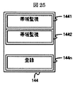
実施例2におけるフロー検索部140のフロー検索テーブル41には、登録対象フローを指定するフロー検索エントリである登録用フロー検索エントリと、実施例1にて説明した帯域監視エントリを参照するためのフロー検索エントリである帯域監視用フロー検索エントリとが設定される。この二種類のフロー検索エントリを区別するため、実施例2におけるフロー検索部も実施例1におけフロー検索部140と同様にフローアクションテーブル制御部とフローアクションテーブルとを備える。ただし、フローアクションテーブル144の構成は、実施例1における図15のフローアクションテーブル143の構成とは異なり、図25のフローアクションテーブル144の構成を有する。
The flow search table 41 of the
図25に示すように、本実施例のフローアクションテーブル144は、図15のようなバッファ番号の情報ではなく、フロー検索エントリが登録フロー検索エントリであるか、帯域監視フロー検索エントリであるかを示す情報から構成される。同図において、「帯域監視」と記載されたフローアクションエントリ1441、1442は、帯域監視用フロー検索エントリに対応して設定され、「登録」と記載されたフローアクションエントリ144nは、登録用フロー検索エントリに対応して設定される。
As shown in FIG. 25, the flow action table 144 of this embodiment is not the buffer number information as shown in FIG. 15, but whether the flow search entry is a registered flow search entry or a bandwidth monitoring flow search entry. It consists of the information shown. In the figure, the
パケット中継装置2の運用管理者が指定した本実施例の登録対象とするフローの条件の情報を管理端末19から入力すると、この入力値がレジスタ29を経由してフロー検索部140のフロー検索テーブル制御部40に入力され、フロー検索テーブル制御部40がフロー検索テーブル41に対し書き込み制御することにより、フロー検索テーブル41にフロー登録用フロー検索エントリが設定される。
When the flow condition information to be registered in the present embodiment specified by the operation manager of the
一方、本実施例のパケット中継装置2にパケットが入力して、当該パケットのパケットヘッダの情報がフロー検索テーブル41のフロー検索エントリに記載されたフローの条件に一致し、当該フロー検索エントリのアドレスを読み出しアドレスとしてフローアクションテーブル制御部142から読み出したフローアクションテーブル144のフローアクションエントリに「登録」を指示する情報が記載されていた場合は、入力パケットは登録用フロー検索エントリに一致したとフローアクションテーブル制御部142にて判定され、登録用フロー検索エントリ一致を示す情報と入力パケットのパケットヘッダ情報はフロー検索テーブル制御40を経由してレジスタ29に送信され、管理端末19に送信される。
On the other hand, when a packet is input to the
管理端末19では、送信されたパケットヘッダ情報1000を解析して、このパケットヘッダ情報1000に基づいたフローの条件をフロー検索テーブル41に帯域監視用フロー検索エントリとして設定することを指示する情報をレジスタ29経由でフロー検索テーブル制御部40に送信する。フロー検索テーブル制御部40は、この情報に従ってパケットヘッダ情報をフロー検索テーブル41にフロー検索エントリとして書き込み制御して設定する。また、当該のフロー検索エントリのアドレスと同一のアドレスを書き込みアドレスとして、フローアクションテーブル制御部142はフローアクションテーブル144のフローアクションエントリに「帯域監視」を指示する情報を書き込み制御する。更に、予めパケット中継装置の運用管理者が指定した帯域監視に関わる図10のパラメタR510、THR513、THRM514の情報を、レジスタ29経由で帯域監視テーブル制御部50に送信する。帯域監視テーブル制御部50は、当該のフロー検索エントリのアドレスと同一のアドレスを書き込みアドレスとして、R510、THR513、THRM514の情報を帯帯域監視テーブル51の域監視エントリに書き込み制御する。
The
以上で説明した実施例2の処理により、パケット中継装置に入力するパケットのパケットヘッダ情報をパケット中継装置にて自律的に収集し、入力パケットのパケットヘッダ情報に基づいて、フローの条件をパケット中継装置にて自律的にフロー検索テーブルに登録する処理が実現される。 Through the processing of the second embodiment described above, the packet header information of the packet input to the packet relay device is autonomously collected by the packet relay device, and the flow condition is packet relayed based on the packet header information of the input packet. A process of autonomously registering in the flow search table is realized by the apparatus.
続いて、第3の実施例として、上流に位置し本発明に係る構成を有しないパケット中継装置により、ECNマーキングされたパケットの受信を契機に、当該パケットのACKパケットにECEマーキングを実施する構成の実施例を、図26〜図29を用いて、説明する。本実施例3の説明では、実施例2との差分のみを説明する。 Subsequently, as a third embodiment, a configuration in which ECE marking is performed on an ACK packet of the packet by receiving a packet that is ECN-marked by a packet relay device that is located upstream and does not have the configuration according to the present invention. This embodiment will be described with reference to FIGS. In the description of the third embodiment, only differences from the second embodiment will be described.
本実施例では、上流に位置する本発明の構成を備えないパケット中継装置によりECNマーキングされたパケットを検出して、フロー検索テーブルに登録するための上流装置連携登録用フロー検索エントリを、実施例2における登録用フロー検索エントリの直上のアドレスに、パケット中継装置の運用管理者の指定に基づいて登録する。また、上流装置連携登録用フロー検索エントリに基づいて登録される上流装置連携ECEマーキング用フロー検索エントリと上流装置連携解除用フロー検索エントリとを、上流装置連携登録用フロー検索エントリよりも上位アドレスに、パケット中継装置にて自律的に登録する。 In this embodiment, a flow search entry for upstream device cooperation registration for detecting a packet that is ECN-marked by a packet relay device that does not have the configuration of the present invention located upstream and registering it in the flow search table is provided in the embodiment. 2. Register at the address immediately above the registration flow search entry in 2 based on the designation of the operation manager of the packet relay apparatus. In addition, the upstream device cooperation ECE marking flow search entry and the upstream device cooperation release flow search entry registered based on the upstream device cooperation registration flow search entry are assigned higher addresses than the upstream device cooperation registration flow search entry. Register autonomously at the packet relay device.
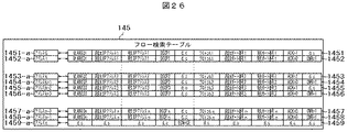
図26に、帯域監視用フロー検索エントリと登録用フロー検索エントリを省略した、本実施例におけるフロー検索テーブル145の構成を示す。フロー検索テーブル145は、TOSフィールドをDSCPフィールドとECNフィールドに分割して設定する点がフロー検索テーブル41と異なる。1451、1453、1455、1457は上流装置連携ECEマーキング用フロー検索エントリ、1452、1454、1456、1458は上流装置連係解除用フロー検索エントリ、1459は上流装置連登録用フロー検索エントリである。1451と1452、1453と1454、1455と1456、1457と1458は対になるフロー検索エントリとして本実施例のパケット中継装置2により自律的に登録され、上流装置連携ECEマーキング用フロー検索エントリではACK=1、上流装置連携解除用フロー検索エントリではACK=0かつCWR=1とする他は、全てのフローの条件に関し互いに一致している。
FIG. 26 shows the configuration of the flow search table 145 in this embodiment in which the bandwidth monitoring flow search entry and the registration flow search entry are omitted. The flow search table 145 is different from the flow search table 41 in that the TOS field is divided and set into a DSCP field and an ECN field.
実施例2で説明した登録用フロー検索エントリではECNフィールド=d.c.として上流パケット中継装置による輻輳検出有無によらずにパケット検出するのに対し、上流装置連携登録用フロー検索エントリ1459はECNフィールド=CEと設定して上流パケット中継装置による輻輳検出済パケットのみを検出する点が異なる。また、実施例2で説明した帯域監視用フロー検索エントリではTOSフィールドの下位2ビットとしてECNフィールドも入力パケットのパケットヘッダの値を登録したのに対し、上流装置連携ECNマーキング用フロー検索エントリ1451、1453、1455、1457と上流装置連係解除用フロー検索エントリ1452、1454、1456、1458ではECNフィールド=d.c.として、登録時の入力パケットのECNフィールド=CEであっても、上流装置連携ECNマーキング用フロー検索エントリではECN≠CEのパケットも検出する点が異なる。
In the registration flow search entry described in the second embodiment, the ECN field = dc is used to detect a packet regardless of the presence or absence of congestion detected by the upstream packet relay device, whereas the upstream device cooperation registration
これは、ECNの規定では、受信端末がECN=CEのパケットを受信すると、その後CWR=1のパケットを受信するまでは、ECN≠CEのパケットを受信した場合であってもECE=1のACKパケットを送信し続ける処理に対応している。本実施例のパケット中継装置がECN=CEのパケットを受信すると、その後CWR=1のパケットを受信するまでは、ECN≠CEのパケットを受信した場合であっても、受信したACKパケットのECEを’1’に書き換えて送信し続ける。 According to the ECN standard, when the receiving terminal receives a packet with ECN = CE, until it receives a packet with CWR = 1, an ACK with ECE = 1 even if a packet with ECN ≠ CE is received. It supports processing that keeps sending packets. When the packet relay apparatus of this embodiment receives a packet with ECN = CE, until the packet with CWR = 1 is received, the ECE of the received ACK packet is received even if a packet with ECN ≠ CE is received. Rewrite to “1” and continue sending.
次に、図27に、実施例2における帯域監視用フロー検索エントリに対応するフローアクションエントリと登録用フロー検索エントリに対応するフローアクションエントリを省略した、本実施例におけるフローアクションテーブル146の構成を示す。フローアクションテーブル146では、上流装置連携ECEマーキング用フロー検索エントリに対応するフローアクションエントリ1461には「上流装置連携ECEマーキング」を指示する情報を記載し、上流装置連係解除用フロー検索エントリに対応するフローアクションエントリ1462には「上流装置連係解除」を指示する情報を記載し、上流装置連携登録用フロー検索エントリに対応するフローアクションエントリ146nには「上流装置連携登録」を指示する情報を記載する。
Next, FIG. 27 shows the configuration of the flow action table 146 in this embodiment in which the flow action entry corresponding to the bandwidth monitoring flow search entry and the flow action entry corresponding to the registration flow search entry in the second embodiment are omitted. Show. In the flow action table 146, the
本実施例のパケット中継装置に、上流に位置する本発明の構成を備えないパケット中継装置によりECNマーキングされたECN=CEのパケットが入力すると、当該パケットのパケットヘッダ情報はフロー検索テーブル145において、予めパケット中継装置の運用管理者の指定に基づいて登録された上流装置連携登録用フロー検索エントリ1459に記載されたフローの条件に一致する。すると、当該上流装置連携登録用フロー検索エントリ1459のアドレスを読み出しアドレスとしてフローアクションテーブル制御部142から読み出したフローアクションテーブル146のフローアクションエントリに「上流装置連携登録」を指示する情報が記載されていた場合は、入力パケットは上流装置連携登録用フロー検索エントリに一致したものと、フローアクションテーブル制御部142にて判定される。
When a packet of ECN = CE that is ECN-marked by a packet relay device that does not have the configuration of the present invention located upstream is input to the packet relay device of this embodiment, the packet header information of the packet is stored in the flow search table 145. This matches the flow conditions described in the upstream device cooperation registration
上流装置連携登録用フロー検索エントリ一致を示す情報と入力パケットのパケットヘッダ情報はフロー検索テーブル制御部40を経由してレジスタ29に送信され、管理端末19に送信される。管理端末19では、送信されたパケットヘッダ情報を解析して、このパケットヘッダ情報に基づいたフローの条件をフロー検索テーブル41に上流装置連携ECEマーキング用フロー検索エントリと上流装置連係解除用フロー検索エントリとして設定することを指示する情報をレジスタ29経由でフロー検索テーブル制御部40に送信する。この際、上流装置連携ECEマーキング用フロー検索エントリと上流装置連係解除用フロー検索エントリのECNフィールドはd.c.として登録する。フロー検索テーブル制御部40は、この情報に従ってパケットヘッダ情報をフロー検索テーブル41に上流装置連携ECEマーキング用フロー検索エントリと上流装置連係解除用フロー検索エントリを書き込み制御して設定する。また、当該の上流装置連携ECEマーキング用フロー検索エントリのアドレスと同一のアドレスを書き込みアドレスとして、フローアクションテーブル制御部142はフローアクションテーブル146のフローアクションエントリに「上流装置連携ECEマーキング」を指示する情報を書き込み制御する。また、当該の上流装置連携解除用フロー検索エントリのアドレスと同一のアドレスを書き込みアドレスとして、フローアクションテーブル制御部142はフローアクションテーブル146のフローアクションエントリに「上流装置連携解除」を指示する情報を書き込み制御する。
Information indicating that the upstream device cooperation registration flow search entry matches and the packet header information of the input packet are transmitted to the register 29 via the flow search
次に、実施例3のパケット中継装置に、TCPのACKパケットが入力した場合の処理について説明する。TCPのACKパケットが本実施例のパケット中継装置に入力すると、パケットヘッダ情報の送信元IPアドレスと宛先IPアドレス、送信元ポート番号と宛先ポート番号を交換するパケットヘッダ条件交換を行ってから、フロー検索テーブル制御部40からフロー検索テーブル41に対し検索起動をかける。検索の結果、上流装置連携ECEマーキング用フロー検索エントリとして登録したフローの条件に対し、パケットヘッダ条件交換を行った後に一致するパケットヘッダ情報をもつパケットが本実施例のパケット中継装置に入力すると、フロー検索テーブル145において一致する上流装置連携ECEマーキング用フロー検索エントリのアドレスを読み出しアドレスとしてフローアクションテーブル制御部42から読み出したフローアクションテーブル146のフローアクションエントリに「上流装置連携ECEマーキング」を指示する情報が記載されていた場合は、入力パケットは上流装置連携ECEマーキング用フロー検索エントリに一致したとフローアクションテーブル制御部142にて判定され、上流装置連携ECEマーキング用フロー検索エントリ一致を示す情報はフロー検索テーブル制御部40を経由してパケット受信回路21に送信される。すると、このACKパケットのパケットヘッダ情報1000を、パケット受信バッファ制御部210がパケット受信バッファ211から読み出し制御して、このパケットヘッダ情報1000におけるTCPフラグフィールド1042のECEフィールド10421の値を1に書き換える。これにより、ACKパケットに対するECEマーキングを、パケット中継装置におけるパケット受信バッファ211の輻輳状態に基づいて、受信端末ではなくパケット中継装置で実施することができる。従って、パケット中継装置から受信端末、受信端末からパケット中継装置、パケット中継装置から送信端末の経路で輻輳通知することができる。当該のACKパケットが上流装置連携ECEマーキング用フロー検索エントリに一致しない場合は、ECEマーキング処理はしない。ACKパケットではACK=1なので、ACK=0かつCWR=1の上流装置連携解除用フロー検索エントリに一致することは無い。
Next, processing when a TCP ACK packet is input to the packet relay apparatus according to the third embodiment will be described. When a TCP ACK packet is input to the packet relay device of this embodiment, the packet header condition exchange for exchanging the source IP address and destination IP address, source port number and destination port number of the packet header information is performed, and then the flow The search is started for the flow search table 41 from the search
一方、CWR=1のデータパケットが実施例3のパケット中継装置に入力した場合には、上述のパケットヘッダ条件交換を行わずにフロー検索テーブル制御部40からフロー検索テーブル41に対し検索起動をかける。検索の結果、当該データパケットのパケットヘッダ情報1000が上流装置連係解除用フロー検索エントリのフローの条件に一致した場合には、フロー検索制御部40から一致した上流装置連係解除用フロー検索エントリと、当該エントリと対として登録された上流装置連係ECEマーキング用フロー検索エントリを削除する制御を行う。次に、一致した上流装置連係解除用フロー検索エントリのアドレスと同一アドレスにあるフローアクションテーブル143のフローアクションエントリの「上流装置連係解除」を指示する情報を削除する。また、当該エントリと対として登録された上流装置連係ECEマーキング用フロー検索エントリのアドレスと同一アドレスにあるフローアクションテーブル143のフローアクションエントリの「上流装置連係ECEマーキング」を指示する情報を削除する。
On the other hand, when a data packet with CWR = 1 is input to the packet relay apparatus of the third embodiment, the flow search
以上に述べた実施例3のパケット中継装置における処理をフローチャートにまとめ、送信端末、受信端末とパケット中継装置間でなされる本実施例の通信の概要をシーケンス図にまとめて説明する。 The processing in the packet relay device of the third embodiment described above is summarized in a flowchart, and the outline of communication of the present embodiment performed between the transmission terminal, the reception terminal, and the packet relay device is described in a sequence diagram.
図28に、実施例3のパケット中継装置における処理のフローチャートを示す。本実施例では、図23に示した実施例1のフローチャートの処理に加え、入力パケットのECNフィールドが”11”、つまりCEであるか否かの判定が追加となる。入力パケットのECNフィールドが”11”でない場合は、実施例1と同様にパケット中継装置内での輻輳検出を判定する処理に移行する。入力パケットのECNフィールドが、”11”である場合は実施例3に特徴的な処理として、当該パケットのパケットヘッダ情報1000のパケットヘッダ条件交換を行い、当該パケットの属するフローに対し受信端末から送信されるACKパケットに対する上流装置連携ECEマーキング用フロー検索エントリと、当該パケットの属するフローでCWR=1のデータパケットに対する上流装置連係解除用フロー検索エントリをフロー検索テーブルに追加となる。
FIG. 28 is a flowchart of processing in the packet relay device according to the third embodiment. In the present embodiment, in addition to the processing of the flowchart of the first embodiment shown in FIG. 23, the determination whether the ECN field of the input packet is “11”, that is, CE, is added. When the ECN field of the input packet is not “11”, the process proceeds to a process for determining congestion detection in the packet relay apparatus as in the first embodiment. When the ECN field of the input packet is “11”, the packet header condition of the
また本実施例では、入力パケットがACKパケットである場合には、当該ACKパケットが上流装置連携ECEマーキング用フロー検索エントリに一致するか否かの判定を行い、一致する場合には、ECEマーキングを行う処理が追加となる。一致しない場合には実施例1と同様に、当該フローに対する輻輳状態管理テーブルを参照し、当該フローが輻輳状態にある場合にはECEマーキングを行う。 In this embodiment, when the input packet is an ACK packet, it is determined whether or not the ACK packet matches the upstream device cooperation ECE marking flow search entry. Additional processing to be performed. If they do not match, the congestion state management table for the flow is referred to as in the first embodiment, and if the flow is in a congestion state, ECE marking is performed.
また本実施例では、入力パケットがACKパケットではない場合、つまりデータパケットで、かつCWR=1である場合には、当該フローのパケットのパケットヘッダ情報が一致する上流装置連携ECEマーキング用フロー検索エントリと、当該フローのパケットのパケットヘッダ情報が一致する上流装置連係解除用フロー検索エントリを削除する処理と、当該フローの非輻輳状態を輻輳状態管理テーブルに記録する処理が追加となる。 In this embodiment, if the input packet is not an ACK packet, that is, if it is a data packet and CWR = 1, the upstream device cooperation ECE marking flow search entry matches the packet header information of the packet of the flow. In addition, a process for deleting the upstream device association release flow search entry that matches the packet header information of the packet of the flow and a process of recording the non-congested state of the flow in the congestion state management table are added.
次に、図29に、実施例3のパケット中継装置を用いた通信のシーケンス図を示す。本実施例のシーケンス図では、実施例1の通信のシーケンス図24における通信構成要素である送信端末1、パケット中継装置2、受信端末3に加え、上流側中継装置(upstream Router)が追加となる。上流側中継装置は、パケット中継装置2よりも上流に位置する中継装置であり、本発明の構成を備えない中継装置であるものとする。パケット中継装置2は、上流側中継装置にてECNマーキングを実施されたSEQ=4001−5000のパケットであるDATA(ECE)を受信することにより、上流側中継装置における輻輳を検出し、これを契機としてそれ以降受信した当該パケットに対するACKパケット、つまりSEQ=4001以降のACKパケットに対しECEマーキングを実施する。これにより、上流に位置する本発明の機能構成を備えないパケット中継装置によりECNマーキングされたパケット受信を契機として、パケット中継装置2は、当該パケットに対するACKパケットにECEマーキングを実現して、送信端末1に送信することができる。
Next, FIG. 29 shows a sequence diagram of communication using the packet relay device of the third embodiment. In the sequence diagram of the present embodiment, an upstream relay device (upstream Router) is added in addition to the
次に、第4の実施例のパケット中継装置を説明する。以下の説明では、実施例4の特徴的な処理のみを説明する。実施例4として、TCPの3way handshakeによる初期化処理を含め、受信端末におけるECNに関する処理の全てをパケット中継装置にて代行する構成について説明する。この構成により、受信端末がECNをサポートしていない場合にも、送信端末とパケット中継装置間でECNをサポートした通信が可能となる。なお本実施例のパケット中継装置では、ECNサポートのデータパケットであるDATA(ECT)や、ECNにおける輻輳回避制御が実施済であることを示すデータパケットDATA(CWR)を、ECN非サポートのデータパケットDATA(not−ECT)に書き換える隠蔽処理を行うことにより、受信端末に対するECN通信はなされないようにする。 Next, a packet relay apparatus according to a fourth embodiment will be described. In the following description, only the characteristic processing of the fourth embodiment will be described. As a fourth embodiment, a description will be given of a configuration in which all processing related to ECN in a receiving terminal is performed by a packet relay device, including initialization processing by TCP 3-way handshake. With this configuration, even when the receiving terminal does not support ECN, communication that supports ECN is possible between the transmitting terminal and the packet relay apparatus. In the packet relay apparatus according to the present embodiment, data (ECT) that is an ECN-supported data packet and data packet DATA (CWR) that indicates that congestion avoidance control in ECN has been performed are not supported by ECN. By performing a concealment process that rewrites to DATA (not-ECT), ECN communication to the receiving terminal is prevented.
図30に、本実施例におけるフロー検索テーブルの構成を示す。フロー検索テーブル147は、SYNフィールドとECEフィールドを設けた点がフロー検索テーブル145と異なる。1471はSYN−ACKパケット検出用フロー検索エントリ、1472はACKパケット検出用フロー検索エントリ、11473はDATA(ECT)パケット検出用フロー検索エントリ、1474はDATA(CWR)パケット検出用フロー検索エントリ、1475はFINパケット検出用フロー検索エントリ、1476はECN−setup SYNパケット検出用フロー検索エントリである。1471〜1475は一組のフロー検索エントリとして本実施例のパケット中継装置により自律的に登録され、ACK、SYN、ECE、CWR、FINフィールドから構成されるTCPフラグフィールドとECNフィールドの他は、全てのフローの条件に関し互いに一致している。ECN−setup SYNパケット検出用フロー検索エントリ1476は、任意のACK=0かつSYN=1かつECE=1かつCWR=1のECN−setup SYNパケットを検出する。
FIG. 30 shows the configuration of the flow search table in the present embodiment. The flow search table 147 is different from the flow search table 145 in that a SYN field and an ECE field are provided. 1471 is a flow search entry for detecting SYN-ACK packets, 1472 is a flow search entry for detecting ACK packets, 11473 is a flow search entry for detecting DATA (ECT) packets, 1474 is a flow search entry for detecting DATA (CWR) packets, and 1475 is FIN packet detection
次に、図31に、実施例4における上述のフロー検索エントリに対応するフローアクションテーブル148の構成を示す。フローアクションテーブル148では、SYN−ACKパケット検出用フロー検索エントリ1471に対応するフローアクションエントリ1481には「ECEマーキング」を指示する情報が記載される。これは、ECNサポートしていない受信端末が送信したECN非サポートを意味するSYN−ACKパケット、つまりECE=0のSYN−ACKパケットを、ECNサポートを意味するSYN−ACKパケット、つまりECE=1のSYN−ACKパケットに、本実施例4のパケット中継装置にて書き換えることを指示する。
Next, FIG. 31 shows the configuration of the flow action table 148 corresponding to the above-described flow search entry in the fourth embodiment. In the flow action table 148, information indicating “ECE marking” is described in the
ACKパケット検出用フロー検索エントリ1472に対応するフローアクションエントリ1482には「輻輳時ECEマーキング」を指示する情報が記載される。これは、パケット中継装置にて輻輳を検出した場合、それ以降CWR=1のデータパケットを検出するまでの間は、ACKパケット検出用フロー検索エントリ1472にて検出されたACKパケットに対し、本実施例のパケット中継装置にてECEマーキングを行うことを指示する。
In the
DATA(ECT)パケット検出用フロー検索エントリ1473に対応するフローアクションエントリ1483には「not−ECTマーキング」を指示する情報が記載される。これは、DATA(ECT)パケット検出用フロー検索エントリ1473にて検査検出されたDATA(ECT)パケット、つまりECNフィールド=”01”または”10”または”11”のデータパケットを、DATA(not−ECT)パケット、つまりECNフィールド=”00”のデータパケットに、本実施例のパケット中継装置にて書き換えることを指示する。
The
DATA(CWR)パケット検出用フロー検索エントリ1474に対応するフローアクションエントリ1484には「ECEマーキング停止¬−ECTマーキング」を指示する情報が記載される。これは、DATA(CWR)パケット検出用フロー検索エントリ1474にて検出されたDATA(CWR)パケット、つまりCWR=1のデータパケットを、DATA(not−ECT)パケット、つまりECNフィールド=”00”かつCWR=0のデータパケットに、本実施例のパケット中継装置にて書き換え、かつ輻輳状態管理テーブルの輻輳状態管理エントリを輻輳状態で無いことを示す値に書き換えることにより、それ以降のACKパケットのECEマーキングを停止することを指示する。
The
FINパケット検出用フロー検索エントリ1475に対応するフローアクションエントリ1485には「ECNプロキシ削除」を指示する情報が記載される。これは、ECN−setup SYNパケット検出用フロー検索エントリ1476で検出されたフローに属するSYN−ACKパケットを検出するSYN−ACKパケット検出用フロー検索エントリ1471、データパケットを検出するDATA(ECT)パケット検出用フロー検索エントリ1473、 DATA(CWR)パケット検出用フロー検索エントリ1474、ACKパケットを検出するACKパケット検出用フロー検索エントリ1472、FINパケットを検出する本FINパケット検出用フロー検索エントリ1475をフロー検索テーブル147から削除し、これらのフロー検索エントリに対応するフローアクションエントリ1481〜1485をフローアクションテーブル148から削除して、それ以降のTCPの3way handshakeによる初期化処理を含めたECNプロキシ処理を停止することを指示する。
In the
ECN−setup SYNパケット検出用フロー検索エントリ1476に対応するフローアクションエントリ1486には「ECNプロキシ登録」を指示する情報が記載される。これは、ECN−setup SYNパケット検出用フロー検索エントリ1476で検出されたフローに属するSYN−ACKパケットを検出するSYN−ACKパケット検出用フロー検索エントリ1471、データパケットを検出するDATA(ECT)パケット検出用フロー検索エントリ1473、DATA(CWR)パケット検出用フロー検索エントリ1474、ACKパケットを検出するACKパケット検出用フロー検索エントリ1472、FINパケットを検出するFINパケット検出用フロー検索エントリ1475をフロー検索テーブル147に登録し、これらのフロー検索エントリに対応するフローアクションエントリ1481〜1485をフローアクションテーブル148に登録することを指示する。
In the
次に、各処理の詳細について説明する。
ACK=0かつSYN=1かつECE=1かつCWR=1かつFIN=0のECN−setup SYNパケットが本実施例のパケット中継装置に入力すると、フロー検索部140のフロー検索テーブル制御部40からフロー検索テーブル147にパケットヘッダ情報1000を入力して検索起動制御がなされ、検索の結果、当該パケットのパケットヘッダ情報1000に一致するECN−setup SYNパケット検出用フロー検索エントリ1476のアドレス1476−aがフロー検索テーブル147から出力される。すると、このアドレス1476−aがフローアクションテーブル制御部42に入力され、アドレス1476−aを読み出しアドレスとしてフローアクションテーブル143を読み出し制御する。すると、「ECNプロキシ登録」を指示する情報が予め記載されたフローアクションエントリ1486が読み出される。すると、この「ECNプロキシ登録」を示す情報とパケットヘッダ情報1000がレジスタ29を経由して管理端末19に送信される。管理端末19では、送信されたパケットヘッダ情報1000を解析して、このパケットヘッダ情報1000に基づいたフローの条件をフロー検索テーブル147に帯域監視用フロー検索エントリとして設定することを指示する情報をレジスタ10経由でフロー検索テーブル制御部40に送信する。管理端末19では、送信されたパケットヘッダ情報1000を解析して、このパケットヘッダ情報1000に基づいたフローの条件をフロー検索テーブル147に、SYN−ACKパケット検出用フロー検索エントリ1471、 ACKパケット検出用フロー検索エントリ1472、DATA(ECT)パケット検出用フロー検索エントリ1473、 DATA(CWR)パケット検出用フロー検索エントリ1474として設定することを指示する情報をレジスタ29経由でフロー検索テーブル制御部40に送信する。
Next, details of each process will be described.
When an ECN-setup SYN packet with ACK = 0, SYN = 1, ECE = 1, CWR = 1 and FIN = 0 is input to the packet relay apparatus of this embodiment, the flow is flown from the flow search
そして、フロー検索テーブル制御部40からフロー検索テーブル147に対し、SYN−ACKパケット検出用フロー検索エントリ1471、 ACKパケット検出用フロー検索エントリ1472、DATA(ECT)パケット検出用フロー検索エントリ1473、 DATA(CWR)パケット検出用フロー検索エントリ1474、FINパケット検出用フロー検索エントリ1475の書き込み制御を行う。なお実際には、DATA(ECT)、DATA(CWR)は入力パケットのECNフィールド値によらずECN=01または10または11の3エントリを設定する。DATA(ECT)に対応するフローアクションエントリ1483も、ECN=01または10または11の3つのDATA(ECT)パケット検出用フロー検索エントリ1473に対応した3つのエントリから構成される。DATA(CWR)に対応するフローアクションエントリ1484も、ECN=01または10または11の3つのDATA(CWR)パケット検出用フロー検索エントリ1474に対応した3つのエントリから構成される。
From the flow search
図30に示す通り、SYN−ACKパケット検出用フロー検索エントリ1471では、パケットヘッダ情報1000に基づいたフローの条件と、パケットヘッダ情報1000によらずACK=1、SYN=1、ECE=0、CWR=0かつFIN=0を設定する。ACKパケット検出用フロー検索エントリ1472では、パケットヘッダ情報1000に基づいたフローの条件と、パケットヘッダ情報1000によらずACK=1、SYN=0、ECE=0、CWR=0かつFIN=0を設定する。DATA(ECT)パケット検出用フロー検索エントリ1473では、パケットヘッダ情報1000に基づいたフローの条件と、パケットヘッダ情報1000によらずACK=0、SYN=0、ECE=0、CWR=0かつFIN=0と、パケットヘッダ情報1000によらずECN=01のエントリと、同じくECN=10のエントリと、同じくECN=11のエントリの3エントリを設定する。DATA(CWR)パケット検出用フロー検索エントリ1474では、パケットヘッダ情報1000に基づいたフローの条件と、パケットヘッダ情報1000によらずACK=0、SYN=0、ECE=0、CWR=1かつFIN=0と、パケットヘッダ情報1000によらずECN=01のエントリと、同じくECN=10のエントリと、同じくECN=11のエントリの3エントリを設定する。
As shown in FIG. 30, in the SYN-ACK packet detection
また、管理端末19では、フローアクションテーブル148のフローアクションエントリ1481に「ECEマーキング」を指示する情報を設定し、フローアクションエントリ1482に「輻輳時ECEマーキング」を指示する情報を設定し、フローアクションエントリ1483に「not−ECTマーキング」を指示する情報を設定し、フローアクションエントリ1484には「ECEマーキング停止¬−ECTマーキング」を指示する情報を設定することを指示する情報をレジスタ10経由でフローアクションテーブル制御部42に送信する。そして、フローアクションテーブル制御部42からフローアクションテーブル148に対し、フローアクションエントリ1481、フローアクションエントリ1482、フローアクションエントリ1483、フローアクションエントリ1484の書き込み制御を行う。
Further, the
次に、ACK=1かつSYN=1かつECE=0かつCWR=0かつFIN=0の、ECN非サポートのSYN−ACKパケットが本実施例4のパケット中継装置に入力すると、フロー検索部140のフロー検索テーブル制御部40からフロー検索テーブル147にパケットヘッダ情報1000を入力して検索起動制御がなされ、検索の結果、当該パケットのパケットヘッダ情報1000に一致するSYN−ACKパケット検出用フロー検索エントリ1471のアドレス1471−aがフロー検索テーブル147から出力される。すると、このアドレス1471−aがフローアクションテーブル制御部142に入力され、アドレス1471−aを読み出しアドレスとしてフローアクションテーブル143を読み出し制御する。すると、「ECEマーキング」を指示する情報がフローアクションエントリ1481から読み出される。すると、この「ECEマーキング」を示す情報がパケット受信回路160のパケット受信バッファ制御部1600に送信され、当該パケットのパケットヘッダ情報1000をパケット受信バッファ1601から読み出し制御して、当該パケットのECE=1に書き換える。すると、本実施例のパケット中継装置にてECN非サポートのSYN−ACKパケットがECNサポートのECN−setup SYN−ACKパケット、つまりACK=1かつSYN=1かつECE=1かつCWR=0かつFIN=0のSYN−ACKに書き換えられて送信されることとなる。このECN−setup SYN−ACKパケットを送信端末が受信して、送信端末がACKパケットを受信端末に送信すると、ECNサポート通信に関するTCP 3way handshake処理が完了する。
Next, when an SYN non-supported SYN-ACK packet with ACK = 1, SYN = 1, ECE = 0, CWR = 0 and FIN = 0 is input to the packet relay apparatus of the fourth embodiment, the
次に、ECNサポート通信が開始されると、ECN=01または10または11のDATA(ECT)パケットが本実施例のパケット中継装置に入力する。ACK=0かつSYN=0かつECE=0かつCWR=0かつFIN=0のDATA(ECT)が本実施例パケット中継装置に入力すると、フロー検索部140のフロー検索テーブル制御部40からフロー検索テーブル147にパケットヘッダ情報1000を入力して検索起動制御がなされ、検索の結果、当該パケットのパケットヘッダ情報1000に一致するDATA(ECT)パケット検出用フロー検索エントリ1473のアドレス1473−aがフロー検索テーブル147から出力される。すると、このアドレス1473−aがフローアクションテーブル制御部142に入力され、アドレス1473−aを読み出しアドレスとしてフローアクションテーブル143を読み出し制御する。すると、「not−ECTマーキング」を指示する情報がフローアクションエントリ1483から読み出される。すると、この「not−ECTマーキング」を示す情報がパケット受信回路160のパケット受信バッファ制御部1600に送信され、当該パケットのパケットヘッダ情報1000をパケット受信バッファ1601から読み出し制御して、当該パケットのECN=00に書き換える。すると、本実施例のパケット中継装置にてECNサポートのDATA(ECT)パケットがECN非サポートのDATA(not−ECT)パケットに書き換えられて送信されることとなる。これにより、送信端末から送信されたECNサポートのデータパケットを、本実施例のパケット中継装置にて非ECNサポートのデータパケットに書き換えて、受信端末に対するECN通信を非ECN通信として隠蔽することができる。
Next, when ECN support communication is started, a DATA (ECT) packet of ECN = 01, 10 or 11 is input to the packet relay apparatus of this embodiment. When DATA (ECT) of ACK = 0, SYN = 0, ECE = 0, CWR = 0, and FIN = 0 is input to the packet relay apparatus of this embodiment, the flow search table is transferred from the flow search
次に、本実施例のパケット中継装置にて書き換えられた非ECNサポートのデータパケットに対するACK=1かつSYN=0かつECE=0かつCWR=0かつFIN=0のACKパケットが本実施例のパケット中継装置に入力すると、フロー検索部140のフロー検索テーブル制御部40からフロー検索テーブル147にパケットヘッダ情報1000を入力して検索起動制御がなされ、検索の結果、当該パケットのパケットヘッダ情報1000に一致するACKパケット検出用フロー検索エントリ1472のアドレス1472−aがフロー検索テーブル147から出力される。すると、このアドレス1472−aがフローアクションテーブル制御部142に入力され、アドレス1472−aを読み出しアドレスとしてフローアクションテーブル143を読み出し制御する。すると、「輻輳時ECEマーキング」を指示する情報がフローアクションエントリ1482から読み出される。すると、この「輻輳時ECEマーキング」を示す情報がパケット受信回路160のバッファ毎輻輳状態管理テーブル制御部1606に送信され、バッファ毎輻輳状態管理テーブル制御部1606によりバッファ毎輻輳状態管理テーブル1607の読み出し制御を行い、当該ACKパケットに対応するデータパケットが蓄積されているバッファの輻輳状態フラグを読み出す。この輻輳状態フラグが輻輳状態にあることを示す値であった場合には、パケット受信バッファ制御部1600によりパケット受信バッファ1601の当該ACKパケットのパケットヘッダ情報1000の読み出し制御を行い、当該ACKパケットのECEフラグを1に書き換える「輻輳時ECEマーキング」の処理を行う。
Next, an ACK packet of ACK = 1, SYN = 0, ECE = 0, CWR = 0, and FIN = 0 for a non-ECN supported data packet rewritten by the packet relay apparatus of this embodiment is a packet of this embodiment. When input to the relay device, the search start control is performed by inputting the
次に、ECEマーキングされたACKパケットにより輻輳を検出して、送信端末1にて輻輳回避制御がなされたことを示すACK=0かつSYN=0かつECE=0かつCWR=1かつFIN=0のDATA(CWR)パケットが本実施例のパケット中継装置に入力すると、フロー検索部140のフロー検索テーブル制御部40からフロー検索テーブル147にパケットヘッダ情報1000を入力して検索起動制御がなされ、検索の結果、当該パケットのパケットヘッダ情報1000に一致するDATA(CWR)パケット検出用フロー検索エントリ1474のアドレス1474−aがフロー検索テーブル147から出力される。すると、このアドレス1474−aがフローアクションテーブル制御部142に入力され、アドレス1474−aを読み出しアドレスとしてフローアクションテーブル143を読み出し制御する。すると、「ECEマーキング停止¬−ECTマーキング」を指示する情報がフローアクションエントリ1484から読み出される。すると、この「ECEマーキング停止」を示す情報がバッファ毎輻輳状態管理テーブル制御部1−15に送信され、バッファ毎輻輳状態管理テーブル制御部1606からバッファ毎輻輳状態管理テーブル1607の当該パケットが蓄積されるバッファに対する輻輳状態管理エントリの輻輳状態フラグの値を、輻輳状態に無いことを示す値に書き換える。これにより、これ以降本実施例のパケット中継装置に入力するACKパケットに対するECEマーキングの処理は停止する。また、「not−ECTマーキング」を示す情報がパケット受信回路160のパケット受信バッファ制御部1600に送信され、当該パケットのパケットヘッダ情報1000をパケット受信バッファ1601から読み出し制御して、当該パケットのECN=00に、CWR=0に書き換える。すると、本実施例のパケット中継装置にてECNサポートのDATA(CWR)パケットがECN非サポートのDATA(not−ECT)パケットに書き換えられて送信されることとなる。これにより、送信端末から送信されたECNサポートのDATA(CWR)パケットを、本実施例のパケット中継装置にて非ECNサポートのDATA(not−ECT)パケットに書き換えて、受信端末に対するECN通信を非ECN通信として隠蔽することができる。
Next, congestion is detected by the ECE-marked ACK packet, and ACK = 0, SYN = 0, ECE = 0, CWR = 1, and FIN = 0 indicating that congestion avoidance control has been performed at the transmitting
次に、通信終了を示すACK=0かつSYN=0かつECE=0かつCWR=0かつFIN=1のFINパケットが本実施例のパケット中継装置に入力すると、フロー検索部140のフロー検索テーブル制御部40からフロー検索テーブル147にパケットヘッダ情報1000を入力して検索起動制御がなされ、検索の結果、当該パケットのパケットヘッダ情報1000に一致するFINパケット検出用フロー検索エントリ1475のアドレス1475−aがフロー検索テーブル147から出力される。すると、このアドレス1475−aがフローアクションテーブル制御部142に入力され、アドレス1475−aを読み出しアドレスとしてフローアクションテーブル143を読み出し制御する。すると、「ECNプロキシ削除」を指示する情報がフローアクションエントリ1485から読み出される。すると、この「ECNプロキシ削除」を示す情報がフローアクションエントリ1482から読み出される。すると、フロー検索テーブル制御部40からフロー検索テーブル147において本FINパケット検出用フロー検索エントリ1475と、本エントリより上位にある4つのエントリとしてSYN−ACKパケット検出用フロー検索エントリ1471、ACKパケット検出用フロー検索エントリ1472、DATA(ECT)パケット検出用フロー検索エントリ1473、 DATA(CWR)パケット検出用フロー検索エントリ1474を削除する。また、フローアクションテーブル制御部142からフローアクションエントリ1481〜1485を削除する。これにより、ECN通信の完了後は当該フローに属するECNプロキシ関連フロー検索エントリとECNプロキシ関連フローアクションエントリを全て削除する。
以上に述べた本実施例のパケット中継装置における処理をフローチャートにまとめ、送信端末、受信端末とパケット中継装置間でなされる本実施例の通信の概要をシーケンス図にまとめて説明する。
Next, when a FIN packet indicating the end of communication ACK = 0, SYN = 0, ECE = 0, CWR = 0, and FIN = 1 is input to the packet relay apparatus of this embodiment, flow search table control of the
The processing in the packet relay apparatus of the present embodiment described above is summarized in a flowchart, and the outline of communication of the present embodiment performed between the transmission terminal, the reception terminal, and the packet relay apparatus is collectively described in a sequence diagram.
図32に本実施例のパケット中継装置における処理フローチャートを示す。
図32に示すフローチャートでは、受信端末がECN非サポートであることを前提とする。本実施例では、実施例1の図23の処理フローに対し、ECN−setup SYNパケットが本実施例のパケット中継装置に入力すると、ECNプロキシ関連エントリ、つまりSYN−ACKパケット検出用フロー検索エントリ1471、ACKパケット検出用フロー検索エントリ1472、 DATA(ECT)パケット検出用フロー検索エントリ1473、 DATA(CWR)パケット検出用フロー検索エントリ1474、FINパケット検出用フロー検索エントリ1475を登録する処理が追加となる。また、FINパケットが本実施例のパケット中継装置に入力すると、ECNプロキシ関連エントリ、つまりSYN−ACKパケット検出用フロー検索エントリ1471、ACKパケット検出用フロー検索エントリ1472、 DATA(ECT)パケット検出用フロー検索エントリ1473、 DATA(CWR)パケット検出用フロー検索エントリ1474、FINパケット検出用フロー検索エントリ1475を削除する処理が追加となる。また、SYN−ACKパケットが本実施例のパケット中継装置に入力すると、当該パケットをECE=1のECN−setup SYN−ACKパケットに書き換えて送信する処理が追加となる。また、DATA(CWR)パケットが本実施例のパケット中継装置に入力すると、当該パケットをECN=00のECN非サポートパケットに書き換えて送信する処理が追加となる。また、その他のデータパケットが本実施例のパケット中継装置に入力すると、当該パケットをECN=00のECN非サポートパケットに書き換えて送信する処理が追加となる。
FIG. 32 shows a processing flowchart in the packet relay apparatus of this embodiment.
In the flowchart shown in FIG. 32, it is assumed that the receiving terminal does not support ECN. In the present embodiment, when an ECN-setup SYN packet is input to the packet relay apparatus of the present embodiment with respect to the processing flow of FIG. 23 of the first embodiment, an ECN proxy-related entry, that is, a SYN-ACK packet detection
最後に、図33に、本実施例のパケット中継装置を用いた通信のシーケンス図を示す。本実施例のシーケンス図では、実施例1のシーケンス図24に対し、3way−handshakeによるInitializeを含め、受信端末3におけるECNの手続きをパケット中継装置2で代行するECNプロキシの処理と、パケット中継装置2で、DATA(ECT)やDATA(CWR)をDATA(not−ECT)に書き換えて、受信端末3に対するECN通信を隠蔽する処理が追加となる。
Finally, FIG. 33 shows a sequence diagram of communication using the packet relay device of this embodiment. In the sequence diagram of the present embodiment, in contrast to the sequence diagram 24 of the first embodiment, the ECN proxy processing in which the
以上、本発明の種々の実施例の説明を行ったが、本発明は上記した実施例に限定されるものではなく、様々な変形例が含まれる。例えば、上記した実施例は本発明を分かりやすく説明するために詳細に説明したのであり、必ずしも説明の全ての構成を備えるものに限定されものではない。また、ある実施例の構成の一部を他の実施例の構成に置き換えることが可能であり、また、ある実施例の構成に他の実施例の構成を加えることが可能である。また、各実施例の構成の一部について、他の構成の追加・削除・置換をすることが可能である。 Although various embodiments of the present invention have been described above, the present invention is not limited to the above-described embodiments, and includes various modifications. For example, the above-described embodiments have been described in detail in order to explain the present invention in an easy-to-understand manner, and are not necessarily limited to those having all the configurations described. Further, a part of the configuration of one embodiment can be replaced with the configuration of another embodiment, and the configuration of another embodiment can be added to the configuration of one embodiment. Further, it is possible to add, delete, and replace other configurations for a part of the configuration of each embodiment.
また、上記の各構成、機能、処理部、処理手段等は、それらの一部又は全部を、例えば集積回路で設計する等によりハードウェアで実現してもよい。また、上記の各構成、機能等は、それぞれの機能を実現するプログラムを実行することで実現したが、これらの各機能を実現するプログラム、テーブル、ファイル等の情報は、メモリや、ハードディスク、SSD(Solid State Drive)等の記録装置、または、ICカード、SDカード、DVD等の記録媒体におくことができるし、必要に応じてネットワーク等を介してダウンロード、インストロールすることも可能である。 Each of the above-described configurations, functions, processing units, processing means, and the like may be realized by hardware by designing a part or all of them with, for example, an integrated circuit. In addition, each of the above-described configurations, functions, and the like are realized by executing a program that realizes each function. However, information such as a program, a table, and a file that realizes each function is stored in a memory, a hard disk, an SSD, or the like. (Solid State Drive) or a recording device such as an IC card, an SD card, or a DVD, and can be downloaded and installed via a network or the like as necessary.
以上詳述したように、本明細書においては、特許請求の範囲に記載した発明以外に、種々の発明が開示されている。その一部を下記に適用例として列記する。 As described above in detail, in the present specification, various inventions are disclosed in addition to the inventions described in the claims. Some of these are listed below as application examples.
[適用例1]
複数の入力回線と出力回線を備え、
入力回線から受信したパケットの入力物理回線番号、または入力論理回線番号、またはパケットヘッダ情報のうち少なくとも一つ以上の情報により識別されるパケットの集合から構成されるフローを検出し、
フローが輻輳状態にあるとパケット中継装置が判定すると、
それ以降にパケット中継装置が受信した当該フローに対する応答パケットのパケットヘッダのうちネットワークの輻輳状態を示すフィールドを輻輳状態にあることを示す値に書き換えることを特徴とするパケット中継装置。
[適用例2]
適用例1のパケット中継装置において、
フロー毎の輻輳状態を記録するフロー毎の輻輳状態フラグから構成される輻輳状態管理テーブルを備え、
フローが輻輳状態にあるとパケット中継装置が判定すると、当該フローの輻輳状態フラグを輻輳状態にあることを示す値に書き換え、
フローが輻輳状態から解消したとパケット中継装置が判定すると、当該フローの輻輳状態フラグを非輻輳状態にあることを示す値に書き換え、
パケット中継装置が応答パケットを受信すると輻輳状態管理テーブルを参照して、応答パケットが属するフローの輻輳状態フラグに従って、
輻輳状態フラグが輻輳を示す場合には応答パケットのパケットヘッダのうちネットワークの輻輳状態を示すフィールドの値を輻輳状態にあることを示す値に書き換え、
輻輳状態フラグが非輻輳状態を示す場合には応答パケットのパケットヘッダのうちネットワークの輻輳状態を示すフィールドの値を非輻輳状態にあることを示す値に書き換えることを特徴とするパケット中継装置。
[Application Example 1]
With multiple input lines and output lines,
Detecting a flow composed of a set of packets identified by at least one of the input physical line number, the input logical line number, or the packet header information of the packet received from the input line,
When the packet relay device determines that the flow is congested,
A packet relay device, wherein a field indicating a network congestion state is rewritten to a value indicating a congestion state in a packet header of a response packet to the flow received by the packet relay device thereafter.
[Application Example 2]
In the packet relay device of Application Example 1,
Congestion state management table composed of a congestion state flag for each flow that records the congestion state for each flow,
When the packet relay apparatus determines that the flow is in a congestion state, the congestion state flag of the flow is rewritten to a value indicating that the flow is in a congestion state,
When the packet relay apparatus determines that the flow has been eliminated from the congestion state, the congestion state flag of the flow is rewritten to a value indicating that the flow is in a non-congestion state,
When the packet relay device receives the response packet, refer to the congestion state management table, and according to the congestion state flag of the flow to which the response packet belongs,
When the congestion state flag indicates congestion, the value of the field indicating the network congestion state in the packet header of the response packet is rewritten to a value indicating that it is in a congestion state.
A packet relay device, wherein, when the congestion state flag indicates a non-congested state, the value of a field indicating a network congestion state in the packet header of a response packet is rewritten to a value indicating that the network is in a non-congested state.
[適用例3]
適用例2のパケット中継装置において、
受信したパケットのパケットヘッダ情報のうち、送信端末が輻輳回避制御を行ったことを示す情報が、輻輳回避を行ったことを示す値となっている場合に、フローが輻輳状態から解消したとパケット中継装置が判定することを特徴とするパケット中継装置。
[Application Example 3]
In the packet relay device of application example 2,
If the information indicating that the sending terminal has performed congestion avoidance control in the packet header information of the received packet is a value indicating that congestion has been avoided, the packet is considered to have been resolved from the congestion state. A packet relay device, characterized in that the relay device determines.
[適用例4]
適用例3のパケット中継装置において、
受信したTCPパケットのCWRフラグが1である場合に、フローが輻輳状態から解消したとパケット中継装置が判定することを特徴とするパケット中継装置。
[Application Example 4]
In the packet relay device of application example 3,
A packet relay apparatus, wherein when a CWR flag of a received TCP packet is 1, the packet relay apparatus determines that the flow has been resolved from a congestion state.
[適用例5]
適用例2から適用例4いずれか記載のパケット中継装置において、
フローが、送信元IPアドレス、宛先IPアドレス、送信元ポート番号、宛先ポート番号の組み合わせが等しいTCPフローまたはDCCPフローまたはSCTPフロー、または送信元IPアドレス、宛先IPアドレスの組み合わせが等しいIPフロー、または同一VLANに属するVLANフロー、またはパケット中継装置の運用管理者が指定した任意のパケットヘッダ情報項目の組み合わせで定義されたフローであることを特徴とするパケット中継装置。
[Application Example 5]
In the packet relay device according to any one of Application Example 2 to Application Example 4,
TCP flow or DCCP flow or SCTP flow with the same combination of source IP address, destination IP address, source port number, destination port number, or IP flow with the same combination of source IP address, destination IP address, or A packet relay apparatus characterized in that it is a VLAN flow belonging to the same VLAN or a flow defined by a combination of arbitrary packet header information items specified by an operation manager of the packet relay apparatus.
[適用例6]
適用例2から適用例5いずれかに記載のパケット中継装置において、
フロー毎の輻輳状態フラグをパケット中継装置の運用管理者が指定した特定フローに対してのみ備えることを特徴とするパケット中継装置。
[Application Example 6]
In the packet relay device according to any one of Application Example 2 to Application Example 5,
A packet relay apparatus comprising a congestion state flag for each flow only for a specific flow designated by an operation manager of the packet relay apparatus.
[適用例7]
適用例1から適用例6いずれかに記載のパケット中継装置において、
応答パケットのパケットヘッダのうちネットワークの輻輳状態を示すフィールドが、TCPパケットのECEフラグであることを特徴とするパケット中継装置。
[Application Example 7]
In the packet relay device according to any one of Application Examples 1 to 6,
A packet relay apparatus, wherein a field indicating a network congestion state in a packet header of a response packet is an ECE flag of a TCP packet.
[適用例8]
適用例1から適用例7いずれかに記載のパケット中継装置において、
シェーパにおけるキュー長、またはポリサにおけるバケツ水量、またはバッファにおける蓄積パケット数が所定の閾値を超過すると、フローが輻輳状態にあると判定することを特徴とするパケット中継装置。
[Application Example 8]
In the packet relay device according to any one of Application Examples 1 to 7,
A packet relay device, wherein a flow is determined to be in a congested state when a queue length in a shaper, a bucket water amount in a policer, or a number of accumulated packets in a buffer exceeds a predetermined threshold.
[適用例9]
適用例1から適用例7いずれかに記載のパケット中継装置において、
受信パケットのパケットヘッダのうちネットワークの輻輳状態を示すフィールドの値に基づいて、フローが輻輳状態にあると判定することを特徴とするパケット中継装置。
[Application Example 9]
In the packet relay device according to any one of Application Examples 1 to 7,
A packet relay device, wherein a flow is determined to be in a congestion state based on a value of a field indicating a network congestion state in a packet header of a received packet.
[適用例10]
適用例9のパケット中継装置において、
受信パケットのパケットヘッダのうちネットワークの輻輳状態を示すフィールドが、IPパケットのECNフィールドであることを特徴とするパケット中継装置。
[Application Example 10]
In the packet relay device of application example 9,
A packet relay apparatus, wherein a field indicating a network congestion state in a packet header of a received packet is an ECN field of an IP packet.
[適用例11]
適用例1から適用例10のいずれかに記載のパケット中継装置において、
輻輳通知機能をサポートしない受信端末から送信された、送受信端末間で輻輳通知機能のサポート可否の情報を通知する制御パケットのパケットヘッダのうち、輻輳通知機能のサポート可否を示すフィールドの値を、輻輳通知機能の非サポートを示す値から輻輳通知機能のサポートを示す値に書き換えることを特徴とするパケット中継装置。
[Application Example 11]
In the packet relay device according to any one of Application Example 1 to Application Example 10,
The value of the field indicating whether the congestion notification function can be supported or not in the packet header of the control packet that notifies the information on whether or not the congestion notification function can be supported between the transmitting and receiving terminals, transmitted from a receiving terminal that does not support the congestion notification function. A packet relay device, wherein a value indicating non-support of a notification function is rewritten to a value indicating support of a congestion notification function.
[適用例12]
適用例11のパケット中継装置において、
ECNによる輻輳通知機能をサポートしない受信端末から送信された、ECNの初期化手順の3way handshake処理におけるECEフラグのセットされていないSYN−ACKパケットを、ECEフラグのセットされたSYN−ACKパケットに書き換えることを特徴とするパケット中継装置。
[Application Example 12]
In the packet relay device of application example 11,
Rewrite a SYN-ACK packet with no ECE flag set in the 3-way handshake process of the ECN initialization procedure sent from a receiving terminal that does not support the ECN congestion notification function to a SYN-ACK packet with the ECE flag set A packet relay device.
1…送信端末
2…パケット中継装置
3…受信端末
14…データ
15…データ(CE)
16…ACK
17…ACK(ECE)
18…データ(CWR)
19…管理端末
21、160…パケット受信回路
22…パケット検索部
23…経路検索部
24、140…フロー検索部
25…帯域監視部
26…パケット中継処理手段
27…パケット検索部
28…パケット送信回路
29…レジスタ
30…出力回線
40…フロー検索テーブル制御部
41、145、147…フロー検索テーブル
50…帯域監視テーブル制御部
51…帯域監視テーブル
52…現在水量判定部
53…監視結果判定部
54…輻輳状態管理部
101…内部ヘッダ部
102…L2ヘッダ部
103…L3ヘッダ部
104…L4ヘッダ部
142…フローアクションテーブル制御部
143、144、146、148…フローアクションテーブル
210、1600…パケット受信バッファ制御部
211、1601…パケット受信バッファ
212、1602…バッファ蓄積パケット数管理部
1000…パケットヘッダ情報
1 ... Sending terminal
2 ... Packet relay device
3 ... Receiving terminal
14 ... Data
15 ... Data (CE)
16 ... ACK
17 ... ACK (ECE)
18 Data (CWR)
19 ... Management terminal
21, 160 ... Packet receiving circuit
22 ... Packet search part
23… Route search part
24, 140 ... Flow search part
25… Bandwidth monitoring unit
26 ... Packet relay processing means
27 ... Packet search part
28 ... Packet transmission circuit
29 ... Register
30 ... Output line
40… Flow search table control unit
41, 145, 147 ... Flow search table
50: Bandwidth monitoring table control unit
51 ... Bandwidth monitoring table
52… Current water quantity determination unit
53 ... Monitoring result judgment unit
54 ... Congestion state management unit
101 ... Internal header
102… L2 header
103 ... L3 header
104 ... L4 header
142… Flow action table control unit
143, 144, 146, 148 ... Flow action table
210, 1600: Packet reception buffer controller
211, 1601 ... Packet reception buffer
212, 1602 ... Number of packets stored in buffer
1000: Packet header information
Claims (9)
複数の入力回線と、
複数の出力回線と、
前記入力回線から受信した前記データパケット或いは前記応答パケットの出力先を検索し、
前記送信側から前記受信側に向けて転送される前記データパケットに含まれる前記送信側と前記受信側に関する情報の組み合わせに対応するフロー毎に、前記送信側と前記受信側との間の輻輳状態を監視し、
前記応答パケットの受信に応じて、当該応答パケットに含まれる前記送信側に関する情報と前記受信側に関する情報とに基づいて、前記送信側と前記受信側に関する情報の組み合わせに対応するフローを特定し、特定したフローが、前記監視の結果により輻輳状態にあると判定すると、前記受信側から受信する当該フローに属する前記データパケットに対応する前記応答パケットのヘッダの内、輻輳状態を示すフィールドを輻輳状態にあることを示す値に書き換え、出力するパケット検索部と、を備え、
前記パケット検索部は、
前記フロー毎の輻輳状態を記録するフロー毎の輻輳状態フラグから構成される輻輳状態管理テーブルを備え、
前記フローが輻輳状態にあると判定すると、当該フローの前記輻輳状態フラグを輻輳状態にあることを示す値に書き換え、
前記フローが輻輳状態から解消したと判定すると、当該フローの前記輻輳状態フラグを非輻輳状態にあることを示す値に書き換え、
前記応答パケットを受信すると前記輻輳状態管理テーブルを参照して、当該応答パケットが属するフローの前記輻輳状態フラグに従って、当該輻輳状態フラグが輻輳状態を示す場合には前記応答パケットのパケットヘッダのうちネットワークの輻輳状態を示すフィールドの値を輻輳状態にあることを示す値に書換え、当該輻輳状態フラグが非輻輳状態を示す場合には前記応答パケットのパケットヘッダのうちネットワークの輻輳状態を示すフィールドの値を輻輳状態にあることを示す値に書き換えず、
前記送信端末から受信したデータパケットのパケットヘッダ情報のうち、前記送信端末が送信帯域を抑制する輻輳回避制御を行ったことを示す情報が、輻輳回避を行ったことを示す値となっている場合に、フローが輻輳状態から解消したと判定する、
ことを特徴とするパケット中継装置。 A packet relay device that relays a data packet transferred between a transmission side including a transmission terminal and a reception side including a reception terminal and a response packet corresponding to the data packet,
Multiple input lines,
Multiple output lines,
Search the output destination of the data packet or the response packet received from the input line,
The congestion state between the transmission side and the reception side for each flow corresponding to a combination of information on the transmission side and the reception side included in the data packet transferred from the transmission side to the reception side Monitor
In response to receiving the response packet, based on the information on the transmission side and the information on the reception side included in the response packet, identify a flow corresponding to a combination of information on the transmission side and the reception side, When it is determined that the identified flow is in a congestion state according to the monitoring result, a field indicating the congestion state is included in the header of the response packet corresponding to the data packet belonging to the flow received from the reception side. rewriting the value indicating that the, Bei example and a packet search unit for outputting,
The packet search unit
A congestion state management table comprising a congestion state flag for each flow that records the congestion state for each flow;
When it is determined that the flow is in a congestion state, the congestion state flag of the flow is rewritten to a value indicating that the flow is in a congestion state,
When it is determined that the flow has been resolved from the congestion state, the congestion state flag of the flow is rewritten to a value indicating that the flow is in a non-congestion state,
When the response packet is received, the congestion state management table is referred to, and when the congestion state flag indicates a congestion state according to the congestion state flag of the flow to which the response packet belongs, the network is included in the packet header of the response packet. The value of the field indicating the congestion state of the response packet is rewritten to the value indicating the congestion state, and when the congestion state flag indicates the non-congestion state, the value of the field indicating the network congestion state in the packet header of the response packet Is not rewritten with a value indicating that it is in a congested state,
Of the packet header information of the data packet received from the transmitting terminal, the information indicating that the transmitting terminal has performed congestion avoidance control for suppressing the transmission band is a value indicating that congestion has been avoided. To determine that the flow has been resolved from the congestion state,
A packet relay device.
前記パケット検索部は、The packet search unit
フロー毎の帯域監視の結果、帯域違反と判定されると、前記フローが輻輳状態にあると判定する、As a result of bandwidth monitoring for each flow, when it is determined that the bandwidth is violated, it is determined that the flow is in a congestion state.
ことを特徴とするパケット中継装置。A packet relay device.
前記フローが、送信元IPアドレス、宛先IPアドレス、送信元ポート番号、宛先ポート番号の組み合わせが等しいTCPフローまたはDCCPフローまたはSCTPフロー、または送信元IPアドレス、宛先IPアドレスの組み合わせが等しいIPフロー、または同一VLANに属するVLANフローである、TCP flow or DCCP flow or SCTP flow with the same combination of source IP address, destination IP address, source port number, destination port number, or IP flow with the same combination of source IP address and destination IP address, Or a VLAN flow belonging to the same VLAN,
ことを特徴とするパケット中継装置。A packet relay device.
前記輻輳状態管理テーブルは、フロー毎の輻輳状態フラグを運用管理者が指定した特定フローに対してのみ備える、The congestion state management table includes a congestion state flag for each flow only for a specific flow designated by the operation manager.
ことを特徴とするパケット中継装置。A packet relay device.
受信したパケットを蓄積するパケット受信バッファを更に備え、A packet reception buffer for storing received packets;
前記パケット受信バッファに蓄積されたパケット数がある閾値を超過すると、前記パケット受信バッファが輻輳状態にあると判定する、When the number of packets accumulated in the packet reception buffer exceeds a certain threshold, it is determined that the packet reception buffer is in a congestion state.
ことを特徴とするパケット中継装置。A packet relay device.
前記パケット検索部は、The packet search unit
輻輳通知機能をサポートしない受信端末から送信された、送受信端末間で輻輳通知機能のサポート可否の情報を通知する制御パケットのパケットヘッダのうち、輻輳通知機能のサポート可否を示すフィールドの値を、輻輳通知機能の非サポートを示す値から輻輳通知機能のサポートを示す値に書き換える、The value of the field indicating whether the congestion notification function can be supported or not in the packet header of the control packet that notifies the information on whether or not the congestion notification function can be supported between the transmitting and receiving terminals, transmitted from a receiving terminal that does not support the congestion notification function. Rewrite from a value indicating non-support of the notification function to a value indicating support of the congestion notification function,
ことを特徴とするパケット中継装置。A packet relay device.
前記受信端末は、ECNによる輻輳通知機能をサポートしない受信端末であり、The receiving terminal is a receiving terminal that does not support a congestion notification function by ECN,
前記パケット検索部は、The packet search unit
前記制御パケットである、ECNの初期化手順の3way handshake処理におけるECEフラグのセットされていないSYN−ACKパケットを、ECEフラグのセットされたSYN−ACKパケットに書き換える、Rewrite the SYN-ACK packet in which the ECE flag is not set in the 3-way handshake process of the ECN initialization procedure, which is the control packet, to a SYN-ACK packet in which the ECE flag is set.
ことを特徴とするパケット中継装置。A packet relay device.
前記パケット検索部は、前記応答パケットが属するフローを検出するフロー検索において、In the flow search for detecting a flow to which the response packet belongs,
送信元IPアドレスと宛先アドレス、送信元ポート番号と宛先ポート番号を交換した条件で検索する、Search with the condition that the source IP address and destination address, source port number and destination port number are exchanged,
ことを特徴とするパケット中継装置。A packet relay device.
前記パケット中継装置は、The packet relay device is:
前記入力回線から受信した前記データパケット或いは当該データパケットに対応する前記応答パケットの出力先を検索し、Search the output destination of the data packet received from the input line or the response packet corresponding to the data packet,
前記送信側から前記受信側に向けて転送される前記データパケットに含まれる前記送信側と前記受信側に関する情報の組み合わせに対応するフロー毎に、前記送信側と前記受信側との間の輻輳状態を監視し、The congestion state between the transmission side and the reception side for each flow corresponding to a combination of information on the transmission side and the reception side included in the data packet transferred from the transmission side to the reception side Monitor
前記応答パケットの受信に応じて、当該応答パケットに含まれる前記送信側に関する情報と前記受信側に関する情報とに基づいて、前記送信側と前記受信側に関する情報の組み合わせに対応するフローを特定し、特定したフローが、前記監視の結果により輻輳状態にあると判定すると、前記受信側から受信する当該フローに属する前記データパケットに対応する前記応答パケットのヘッダの内、輻輳状態を示すフィールドを輻輳状態にあることを示す値に書き換え出力し、In response to receiving the response packet, based on the information on the transmission side and the information on the reception side included in the response packet, identify a flow corresponding to a combination of information on the transmission side and the reception side, When it is determined that the identified flow is in a congestion state according to the monitoring result, a field indicating the congestion state is included in the header of the response packet corresponding to the data packet belonging to the flow received from the reception side. Rewrite to the value indicating that
前記フロー毎の輻輳状態を記録するフロー毎の輻輳状態フラグから構成される輻輳状態管理テーブルを書き換えおよび参照可能であり、The congestion state management table composed of the congestion state flag for each flow that records the congestion state for each flow can be rewritten and referred to,
前記フローが輻輳状態にあると判定すると、当該フローの前記輻輳状態フラグを輻輳状態にあることを示す値に書き換え、When it is determined that the flow is in a congestion state, the congestion state flag of the flow is rewritten to a value indicating that the flow is in a congestion state,
前記フローが輻輳状態から解消したと判定すると、当該フローの前記輻輳状態フラグを非輻輳状態にあることを示す値に書き換え、When it is determined that the flow has been resolved from the congestion state, the congestion state flag of the flow is rewritten to a value indicating that the flow is in a non-congestion state,
前記応答パケットを受信すると前記輻輳状態管理テーブルを参照して、当該応答パケットが属するフローの前記輻輳状態フラグに従って、当該輻輳状態フラグが輻輳状態を示す場合には前記応答パケットのパケットヘッダのうちネットワークの輻輳状態を示すフィールドの値を輻輳状態を示す値に書き換え、当該輻輳状態フラグが非輻輳状態を示す場合には前記応答パケットのパケットヘッダのうちネットワークの輻輳状態を示すフィールドの値を輻輳状態を示す値に書き換えず、When the response packet is received, the congestion state management table is referred to, and when the congestion state flag indicates a congestion state according to the congestion state flag of the flow to which the response packet belongs, the network is included in the packet header of the response packet. If the value of the field indicating the congestion state is rewritten to a value indicating the congestion state, and the congestion state flag indicates a non-congestion state, the value of the field indicating the network congestion state in the packet header of the response packet is the congestion state. Without rewriting the value to indicate
前記送信側から受信したデータパケットのパケットヘッダ情報のうち、前記送信側が送信帯域を抑制する輻輳回避制御を行ったことを示す情報が、輻輳回避を行ったことを示す値となっている場合に、フローが輻輳状態から解消したと判定する、Among the packet header information of the data packet received from the transmission side, when the information indicating that the transmission side has performed congestion avoidance control for suppressing the transmission bandwidth is a value indicating that congestion avoidance has been performed , Determine that the flow has cleared from the congestion state,
ことを特徴とするパケット中継方法。A packet relay method.
Priority Applications (3)
| Application Number | Priority Date | Filing Date | Title |
|---|---|---|---|
| JP2011172611A JP5710418B2 (en) | 2011-08-08 | 2011-08-08 | Packet relay apparatus and method |
| PCT/JP2012/052828 WO2013021666A1 (en) | 2011-08-08 | 2012-02-08 | Packet relay device and method |
| US14/006,107 US20140016461A1 (en) | 2011-08-08 | 2012-02-08 | Packet relay device and method |
Applications Claiming Priority (1)
| Application Number | Priority Date | Filing Date | Title |
|---|---|---|---|
| JP2011172611A JP5710418B2 (en) | 2011-08-08 | 2011-08-08 | Packet relay apparatus and method |
Publications (3)
| Publication Number | Publication Date |
|---|---|
| JP2013038570A JP2013038570A (en) | 2013-02-21 |
| JP2013038570A5 JP2013038570A5 (en) | 2014-03-27 |
| JP5710418B2 true JP5710418B2 (en) | 2015-04-30 |
Family
ID=47668199
Family Applications (1)
| Application Number | Title | Priority Date | Filing Date |
|---|---|---|---|
| JP2011172611A Active JP5710418B2 (en) | 2011-08-08 | 2011-08-08 | Packet relay apparatus and method |
Country Status (3)
| Country | Link |
|---|---|
| US (1) | US20140016461A1 (en) |
| JP (1) | JP5710418B2 (en) |
| WO (1) | WO2013021666A1 (en) |
Families Citing this family (16)
| Publication number | Priority date | Publication date | Assignee | Title |
|---|---|---|---|---|
| US9019967B2 (en) * | 2012-07-30 | 2015-04-28 | Dell Products L.P. | VLAN advertisement and automated configuration |
| US9444748B2 (en) * | 2013-03-15 | 2016-09-13 | International Business Machines Corporation | Scalable flow and congestion control with OpenFlow |
| EP2833589A1 (en) * | 2013-08-02 | 2015-02-04 | Alcatel Lucent | Intermediate node, an end node, and method for avoiding latency in a packet-switched network |
| JP6127900B2 (en) * | 2013-10-18 | 2017-05-17 | 富士通株式会社 | Packet processing apparatus, packet processing method, and packet processing program |
| JP5887324B2 (en) | 2013-11-15 | 2016-03-16 | アラクサラネットワークス株式会社 | Relay device and relay method |
| JP6323107B2 (en) * | 2014-03-25 | 2018-05-16 | 富士通株式会社 | Switch device, information processing system, and control method of switch device |
| US9961585B2 (en) * | 2014-05-16 | 2018-05-01 | Nokia Solutions And Networks Oy | Network-side buffer management |
| US9614766B2 (en) * | 2014-12-16 | 2017-04-04 | Cisco Technology, Inc. | System and method to analyze congestion in low latency network |
| US10068004B2 (en) * | 2015-07-10 | 2018-09-04 | Under Armour, Inc. | System and method for determining the occurrence of organized athletic events |
| CN108432194B (en) * | 2016-04-28 | 2022-02-25 | 华为技术有限公司 | Congestion processing method, host and system |
| KR102380619B1 (en) * | 2017-08-11 | 2022-03-30 | 삼성전자 주식회사 | Method and apparatus of efficient congestion control in a mobile communication system |
| CN109412964B (en) * | 2017-08-18 | 2022-04-29 | 华为技术有限公司 | Message control method and network device |
| CN110581774B (en) * | 2018-06-08 | 2022-12-06 | 华为技术有限公司 | Network communication method and device |
| WO2020104037A1 (en) * | 2018-11-22 | 2020-05-28 | Telefonaktiebolaget Lm Ericsson (Publ) | Acknowlegment for simultaneous transmission and reception |
| CN114257967B (en) * | 2020-09-22 | 2022-10-25 | 华为技术有限公司 | Broadcast-based unicast session method and device |
| CN115396372B (en) * | 2022-10-26 | 2023-02-28 | 阿里云计算有限公司 | Data stream rate control method, intelligent network card, cloud device and storage medium |
Family Cites Families (14)
| Publication number | Priority date | Publication date | Assignee | Title |
|---|---|---|---|---|
| JP2984910B2 (en) * | 1995-11-17 | 1999-11-29 | 株式会社超高速ネットワーク・コンピュータ技術研究所 | Data flow control method |
| JP3556495B2 (en) * | 1998-12-15 | 2004-08-18 | 株式会社東芝 | Packet switch and packet switching method |
| JP3994614B2 (en) * | 2000-03-13 | 2007-10-24 | 株式会社日立製作所 | Packet switch, network monitoring system, and network monitoring method |
| US7359321B1 (en) * | 2002-01-17 | 2008-04-15 | Juniper Networks, Inc. | Systems and methods for selectively performing explicit congestion notification |
| US20070008884A1 (en) * | 2003-10-08 | 2007-01-11 | Bob Tang | Immediate ready implementation of virtually congestion free guarantedd service capable network |
| US7564869B2 (en) * | 2004-10-22 | 2009-07-21 | Cisco Technology, Inc. | Fibre channel over ethernet |
| US7719982B2 (en) * | 2005-08-31 | 2010-05-18 | Intel Corporation | Switching device utilizing flow-control management |
| EP2063576B1 (en) * | 2006-09-28 | 2012-08-01 | Fujitsu Limited | Mobile ip communication system |
| JP2008104027A (en) * | 2006-10-19 | 2008-05-01 | Fujitsu Ltd | Apparatus and program for collecting packet information |
| US8259659B2 (en) * | 2008-07-03 | 2012-09-04 | Apple Inc. | Apparatus and methods for managing access and update requests in a wireless network |
| JP4994323B2 (en) * | 2008-07-25 | 2012-08-08 | アラクサラネットワークス株式会社 | Relay device |
| US20100246400A1 (en) * | 2009-03-26 | 2010-09-30 | Kyocera Corporation | Communication device and method |
| JP5275107B2 (en) * | 2009-03-26 | 2013-08-28 | 京セラ株式会社 | Communication equipment |
| JP5365415B2 (en) * | 2009-08-25 | 2013-12-11 | 富士通株式会社 | Packet relay apparatus and congestion control method |
-
2011
- 2011-08-08 JP JP2011172611A patent/JP5710418B2/en active Active
-
2012
- 2012-02-08 US US14/006,107 patent/US20140016461A1/en not_active Abandoned
- 2012-02-08 WO PCT/JP2012/052828 patent/WO2013021666A1/en active Application Filing
Also Published As
| Publication number | Publication date |
|---|---|
| JP2013038570A (en) | 2013-02-21 |
| WO2013021666A1 (en) | 2013-02-14 |
| US20140016461A1 (en) | 2014-01-16 |
Similar Documents
| Publication | Publication Date | Title |
|---|---|---|
| JP5710418B2 (en) | Packet relay apparatus and method | |
| US20220217078A1 (en) | System and method for facilitating tracer packets in a data-driven intelligent network | |
| JP5538257B2 (en) | Bandwidth monitoring device and packet relay device | |
| US10397124B2 (en) | System and method to prevent persistent full switch queues in software defined networks | |
| EP2887595B1 (en) | Method and node for retransmitting data packets in a tcp connection | |
| KR101746629B1 (en) | Communication apparatus and communication method | |
| EP3120253B1 (en) | Flow aware buffer management for data center switches | |
| US8493867B1 (en) | Retransmission and flow control in a logical network tunnel | |
| US8780719B2 (en) | Packet relay apparatus and congestion control method | |
| JP5967090B2 (en) | COMMUNICATION SYSTEM, CONTROL DEVICE, NODE CONTROL METHOD, AND PROGRAM | |
| US20060221825A1 (en) | Congestion control network relay device and method | |
| WO2019157867A1 (en) | Method for controlling traffic in packet network, and device | |
| US20140185445A1 (en) | Flow-Based Adaptive Private Network with Multiple WAN-Paths | |
| JP5673841B2 (en) | Data communication apparatus, data transmission method and computer system | |
| US10439940B2 (en) | Latency correction between transport layer host and deterministic interface circuit | |
| US10461886B2 (en) | Transport layer identifying failure cause and mitigation for deterministic transport across multiple deterministic data links | |
| Natarajan et al. | Non-renegable selective acknowledgments (NR-SACKs) for SCTP | |
| US9654399B2 (en) | Methods and devices in an IP network for congestion control | |
| JP2008118281A (en) | Communication device | |
| WO2012095904A1 (en) | Communication device, packet retransmission control method and packet retransmission control program | |
| JP5087595B2 (en) | Edge node, window size control method and program | |
| JP2015097316A (en) | Relay device and relay method | |
| WO2015195151A1 (en) | Preventing flow table misses in a software defined network | |
| WO2015128276A1 (en) | Improved traffic control in packet transport networks | |
| CN117395206B (en) | Rapid and accurate congestion feedback method for lossless data center network |
Legal Events
| Date | Code | Title | Description |
|---|---|---|---|
| A521 | Request for written amendment filed |
Free format text: JAPANESE INTERMEDIATE CODE: A523 Effective date: 20140206 |
|
| A621 | Written request for application examination |
Free format text: JAPANESE INTERMEDIATE CODE: A621 Effective date: 20140206 |
|
| RD02 | Notification of acceptance of power of attorney |
Free format text: JAPANESE INTERMEDIATE CODE: A7422 Effective date: 20140908 |
|
| A131 | Notification of reasons for refusal |
Free format text: JAPANESE INTERMEDIATE CODE: A131 Effective date: 20141105 |
|
| A521 | Request for written amendment filed |
Free format text: JAPANESE INTERMEDIATE CODE: A523 Effective date: 20141225 |
|
| TRDD | Decision of grant or rejection written | ||
| A01 | Written decision to grant a patent or to grant a registration (utility model) |
Free format text: JAPANESE INTERMEDIATE CODE: A01 Effective date: 20150224 |
|
| A61 | First payment of annual fees (during grant procedure) |
Free format text: JAPANESE INTERMEDIATE CODE: A61 Effective date: 20150304 |
|
| R150 | Certificate of patent or registration of utility model |
Ref document number: 5710418 Country of ref document: JP Free format text: JAPANESE INTERMEDIATE CODE: R150 |
|
| R250 | Receipt of annual fees |
Free format text: JAPANESE INTERMEDIATE CODE: R250 |
|
| R250 | Receipt of annual fees |
Free format text: JAPANESE INTERMEDIATE CODE: R250 |
|
| R250 | Receipt of annual fees |
Free format text: JAPANESE INTERMEDIATE CODE: R250 |
|
| R250 | Receipt of annual fees |
Free format text: JAPANESE INTERMEDIATE CODE: R250 |
|
| R250 | Receipt of annual fees |
Free format text: JAPANESE INTERMEDIATE CODE: R250 |
|
| R250 | Receipt of annual fees |
Free format text: JAPANESE INTERMEDIATE CODE: R250 |