JP5709908B2 - Battery pack cover, battery module, and battery system - Google Patents
Battery pack cover, battery module, and battery system Download PDFInfo
- Publication number
- JP5709908B2 JP5709908B2 JP2013003981A JP2013003981A JP5709908B2 JP 5709908 B2 JP5709908 B2 JP 5709908B2 JP 2013003981 A JP2013003981 A JP 2013003981A JP 2013003981 A JP2013003981 A JP 2013003981A JP 5709908 B2 JP5709908 B2 JP 5709908B2
- Authority
- JP
- Japan
- Prior art keywords
- assembled battery
- batteries
- battery
- gas
- battery cover
- Prior art date
- Legal status (The legal status is an assumption and is not a legal conclusion. Google has not performed a legal analysis and makes no representation as to the accuracy of the status listed.)
- Active
Links
Images


Classifications
-
- Y—GENERAL TAGGING OF NEW TECHNOLOGICAL DEVELOPMENTS; GENERAL TAGGING OF CROSS-SECTIONAL TECHNOLOGIES SPANNING OVER SEVERAL SECTIONS OF THE IPC; TECHNICAL SUBJECTS COVERED BY FORMER USPC CROSS-REFERENCE ART COLLECTIONS [XRACs] AND DIGESTS
- Y02—TECHNOLOGIES OR APPLICATIONS FOR MITIGATION OR ADAPTATION AGAINST CLIMATE CHANGE
- Y02E—REDUCTION OF GREENHOUSE GAS [GHG] EMISSIONS, RELATED TO ENERGY GENERATION, TRANSMISSION OR DISTRIBUTION
- Y02E60/00—Enabling technologies; Technologies with a potential or indirect contribution to GHG emissions mitigation
- Y02E60/10—Energy storage using batteries
Description
本発明は、安全弁を有する複数の電池が積層されて構成される組電池を覆う組電池カバー、組電池を備えている電池モジュール、電池モジュールを備えている電池システムに関する。 The present invention relates to an assembled battery cover that covers an assembled battery configured by stacking a plurality of batteries having safety valves, a battery module including the assembled battery, and a battery system including the battery module.
複数の電池が積層されて構成される組電池では、多くの場合、各電池に設けられている安全弁の側の防塵や防滴等のため、組電池の安全弁側が蓋やカバー等で覆われている。 In an assembled battery configured by stacking a plurality of batteries, in many cases, the safety valve side of the assembled battery is covered with a lid, a cover, or the like for dust prevention or drip-proofing on the side of the safety valve provided in each battery. Yes.
以下の特許文献1に記載のシステムも、組電池と、この組電池の安全弁側を覆う蓋と、を備えている。このシステムでは、安全弁から噴出したガスを蓋外に排出するために、複数の電池が積層されている積層方向における蓋の端部に、排気ダクトを設けている。
The system described in
上記特許文献1に記載のシステムでは、組電池を構成する複数の電池のうち、いずれか一の電池の安全弁からガスが噴出した場合、このガスは、一の電池を基準にして積層方向における排気ダクト側の電池上を通過して、この排気ダクトから外部へ排出される。このため、上記特許文献1に記載のシステムでは、噴出したガスにより、他の電池、特に、ガスが噴出した電池と隣接する電池が悪影響を受ける可能性が高いという問題点がある。具体的には、噴出した高温のガスが隣接する電池の上部を流れていくことにより、他の電池も高温のガスに晒されてしまい、結果として、他の電池に悪影響を及ぼすことが考えられる。
In the system described in
そこで、本発明は、このような従来技術の問題点に着目し、複数の電池のうちの一の電池の安全弁からガスが噴出した場合でも、他の電池への悪影響を抑えることができる組電池カバー、電池モジュール、電池システムを提供することを目的とする。 Therefore, the present invention pays attention to such problems of the prior art, and even when gas is ejected from the safety valve of one of the plurality of batteries, the assembled battery can suppress adverse effects on other batteries. An object is to provide a cover, a battery module, and a battery system.
前記問題点を解決するための発明に係る一態様としての組電池カバーは、
安全弁を有する複数の電池が積層されて構成される組電池の前記安全弁側を覆う組電池カバーにおいて、複数の電池における前記安全弁が設けられている面である蓋面と間隔をあけて対向する天板部と、前記天板部の外周縁から、前記電池の前記蓋面に隣接する側周面にまで延びる側周板部と、前記天板部と前記側周板部とに囲まれたカバー内領域に設けられ、複数の前記電池の各安全弁から噴出したガスを、複数の電池が積層されている積層方向に対して垂直な方向に導くガスガイド部と、を有し、前記側周板部のうちで前記積層方向に広がる部分である側板部と、前記天板部とのうちの一方で、前記積層方向で複数の前記電池の各安全弁と重なる位置に、前記カバー内領域から外部へ貫通する開口が前記ガスにより形成される開放部が形成されていることを特徴とする。
An assembled battery cover as one aspect according to the invention for solving the above problems is
In an assembled battery cover that covers the safety valve side of an assembled battery that is configured by stacking a plurality of batteries having safety valves, a ceiling facing the lid surface that is a surface on which the safety valves are provided in the plurality of batteries with a space therebetween A cover surrounded by a plate portion, a side peripheral plate portion extending from an outer peripheral edge of the top plate portion to a side peripheral surface adjacent to the lid surface of the battery, and the top plate portion and the side peripheral plate portion provided on the inner region, it has a gas ejected from the safety valve of the plurality of the battery, a gas guide portion for guiding a direction perpendicular to the stacking direction in which the plurality of batteries are stacked, the said side peripheral plate The side plate portion that is a portion extending in the stacking direction among the portions, and the top plate portion, on the position overlapping with the safety valves of the plurality of batteries in the stacking direction, from the cover inner region to the outside The opening that penetrates the opening is formed by the gas. Characterized in that it is.
当該組電池カバーでは、複数の電池のうちのいずれかの電池の安全弁からガスが噴出しても、このガスの積層方向への流れがガスガイド部により規制されるため、ガスが噴出した電池に対して積層方向に並んでいる他の電池へのガスの悪影響を抑えることができる。さらに、当該組電池カバーでは、ガスガイド部により積層方向に対して垂直な方向に導かれたガスを開放部から組電池カバー外へ流出させることができる。このため、当該組電池カバーでは、電池の安全弁から噴出したガスの流れを、積層方向に対して垂直な方向に効率的に導くことができ、他の電池へのガスの悪影響をより抑えることができる。 In the assembled battery cover, even if gas is ejected from the safety valve of one of the batteries, the flow of the gas in the stacking direction is restricted by the gas guide part. On the other hand, the adverse effect of the gas on other batteries arranged in the stacking direction can be suppressed. Furthermore, in the assembled battery cover, the gas guided by the gas guide portion in the direction perpendicular to the stacking direction can flow out of the assembled battery cover from the open portion. For this reason, in the assembled battery cover, the flow of gas ejected from the safety valve of the battery can be efficiently guided in a direction perpendicular to the stacking direction, and the adverse effect of the gas on other batteries can be further suppressed. it can.
ここで、前記組電池カバーにおいて、前記ガスガイド部は、前記積層方向に対して垂直な方向に延び、前記カバー内領域における複数の前記電池の相互間の位置に設けられているガスガイド板であってもよい。 Here, in the assembled battery cover, the gas guide portion is a gas guide plate that extends in a direction perpendicular to the stacking direction and is provided at a position between the plurality of batteries in the cover inner region. There may be.
前記開放部が形成されている前記組電池カバーにおいて、前記開放部は、前記ガスの熱で溶融する樹脂で形成されていてもよい。 In the assembled battery cover in which the opening portion is formed, the opening portion may be formed of a resin that is melted by the heat of the gas.
また、前記開放部が形成されている、以上のいずれかの前記組電池カバーにおいて、前記開放部は、該開放部周りの部分よりも厚さが薄くてもよい。 In any one of the above assembled battery covers in which the opening portion is formed, the opening portion may be thinner than a portion around the opening portion.
また、前記開放部が形成されている、以上のいずれかの前記組電池カバーにおいて、前記側周板部のうちで前記積層方向に広がる部分である前記側板部と、前記天板部とのうち、前記開放部が形成されていない他方は、金属板を有して形成されていてもよい。 Further, in any one of the above assembled battery covers in which the open portion is formed, the side plate portion that is a portion that extends in the stacking direction among the side peripheral plate portions, and the top plate portion The other side on which the open part is not formed may have a metal plate.
当該組電池カバーでは、側板部と天板部とのうちで開放部が形成されている一方に対して、他方が金属板を有して形成されているため、他方はガスによる損傷を抑えることができ、開放部が形成されている一方側へガスを導くことができる。よって、当該組電池カバーでは、開放部が形成されている一方側から組電池カバー外へ、より確実にガスを流出させることができる。 In the assembled battery cover, since the open portion is formed between the side plate portion and the top plate portion, the other has a metal plate, so the other suppresses gas damage. The gas can be guided to one side where the open portion is formed. Therefore, in the assembled battery cover, the gas can be more reliably flowed out of the assembled battery cover from one side where the open portion is formed.
また、前記開放部が形成されている、以上のいずれかの前記組電池カバーにおいて、前記一方は、前記側板部であってもよい。 Further, in any one of the above assembled battery covers in which the open portion is formed, the one side may be the side plate portion.
この場合、前記天板部は、前記開放部に近づくに連れて前記蓋面との間の距離が大きくなるよう構成されていてもよい。 In this case, the top plate portion may be configured such that a distance between the top plate portion and the lid surface increases as the opening portion approaches.
当該組電池カバーでは、電池の安全弁から噴出したガスが開放部側に流れ易くなるため、開放部から組電池カバー外へ、より確実にガスを流出させることができる。 In the assembled battery cover, the gas ejected from the safety valve of the battery can easily flow to the open portion side, so that the gas can be more reliably discharged from the open portion to the outside of the assembled battery cover.
前記問題点を解決するための発明に係る一態様としての電池モジュールは、
以上のいずれかの前記組電池カバーと、前記組電池と、を備えていることを特徴とする。
The battery module as one aspect according to the invention for solving the above problems is
Any one of the above assembled battery covers and the assembled battery are provided.
当該電池モジュールでは、以上で説明した組電池カバーを備えているので、ガスが噴出した電池に対して積層方向に並んでいる他の電池へのガスの悪影響を抑えることができる。 Since the battery module includes the assembled battery cover described above, it is possible to suppress the adverse effect of the gas on other batteries arranged in the stacking direction with respect to the battery from which the gas has been ejected.
前記問題点を解決するための発明に係る一態様としての電池システムは、
安全弁を有する複数の電池が積層されて構成される組電池と、複数の前記電池の各安全弁から噴出したガスを、複数の電池が積層されている積層方向に対して垂直な方向に導くガスガイド部と、複数の前記電池における前記安全弁が設けられている面である蓋面と間隔をあけて対向配置され、機器を支持可能な機器支持板と、複数の前記電池における前記蓋面と前記機器支持板との間に、前記蓋面と間隔をあけて対向する天板部を有して、前記組電池の前記安全弁側を覆う組電池カバーと、を備え、前記ガスガイド部は、前記機器支持板に設けられ、前記組電池カバーの前記天板部で、複数の前記電池の各安全弁と対向する位置には、前記組電池側から前記機器支持板側へ貫通する開口が前記ガスにより形成される開放部が形成されている、ことを特徴とする。
The battery system as one aspect according to the invention for solving the above problems is
A battery pack configured by stacking a plurality of batteries having safety valves, and a gas guide for guiding the gas ejected from each safety valve of the plurality of batteries in a direction perpendicular to the stacking direction in which the plurality of batteries are stacked A device support plate that is arranged to be opposed to and spaced from a lid surface that is a surface on which the safety valve is provided in the plurality of batteries, and that can support the device, and the lid surface and the device in the plurality of batteries An assembled battery cover that covers the safety valve side of the assembled battery, and has a top plate portion that is opposed to the cover surface with a gap between the cover plate and the gas guide unit, An opening penetrating from the assembled battery side to the device support plate side is formed by the gas at a position provided on the support plate and facing each safety valve of the plurality of batteries at the top plate portion of the assembled battery cover. opening being is formed, And wherein the door.
当該電池システムでは、複数の電池のうちのいずれかの電池の安全弁からガスが噴出しても、このガスの積層方向への流れがガスガイド部により規制されるため、ガスが噴出した電池に対して積層方向に並んでいる他の電池へのガスの悪影響を抑えることができる。 In the battery system, even if gas is ejected from the safety valve of any one of the plurality of batteries, the flow of the gas in the stacking direction is restricted by the gas guide portion. Thus, adverse effects of gas on other batteries arranged in the stacking direction can be suppressed.
また、機器支持板を備えている前記電池システムにおいて、前記機器は、前記組電池の制御器であってもよいし、複数の前記電池が積層されて構成される組電池であってもよい。 In the battery system including the device support plate, the device may be a controller of the assembled battery, or an assembled battery configured by stacking a plurality of the batteries.
前記組電池カバーは、複数の前記電池の各安全弁から噴出したガスを、複数の電池が積層されている積層方向に対して垂直な方向に導くガスガイド部を有してもよい。 The assembled battery cover may include a gas guide portion that guides gas ejected from each safety valve of the plurality of batteries in a direction perpendicular to a stacking direction in which the plurality of batteries are stacked.
本発明では、複数の電池のうちの一の電池の安全弁からガスが噴出した場合でも、他の電池への悪影響を抑えることができる。 In the present invention, even when gas is ejected from the safety valve of one of the batteries, adverse effects on other batteries can be suppressed.
以下、本発明に係る各種実施形態について、図面を用いて説明する。 Hereinafter, various embodiments according to the present invention will be described with reference to the drawings.
「第一実施形態」
まず、本発明に係る第一実施形態としての電池モジュールについて、図1〜図5を用いて説明する。
"First embodiment"
First, the battery module as a first embodiment according to the present invention will be described with reference to FIGS.
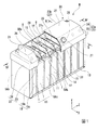
図1に示すように、本実施形態の電池モジュールMは、複数の電池1で構成される組電池10と、組電池10を覆う組電池カバー20と、を備えている。なお、本実施形態において、組電池10とは、複数の電池1で構成されるものを称し、電池モジュールMとは、複数の電池1で構成された組電池10と、組電池カバー20とを有して構成されるものを称することとする。また、本実施形態では、電池1として、リチウムイオン二次電池を一例にとって説明する。
As shown in FIG. 1, the battery module M of the present embodiment includes an assembled
電池1は、図5に示すように、複数の正極板2と、複数の負極板3と、負極板3を覆うセパレータ4と、電解液(不図示)と、これらを収納するセルケース5と、を備えている。
As shown in FIG. 5, the
各電極板2,3は、矩形シート状の集電体に活物質等を塗工されている本体と、矩形シート状の部分の縁から延びているタブとを有している。負極板3の負極板本体3aは、セパレータ4により完全に覆われ、負極板3のタブ3bは、一部がセパレータ4から露出している。セパレータ4は、絶縁性及び耐電解液性を有する樹脂、例えば、ポリエチレンやポリプロピレンのようなポリオレフィン等で形成されている。
Each of the
複数の正極板2と、それぞれがセパレータ4で覆われている複数の負極板3とは、タブ2b,3bが設けられている側が互いに同じ側になるよう、交互に重ね合わされて、電極積層体を形成している。なお、以下では、複数の正極板2及び複数の負極板3が積層されている方向をZ方向、各電極板2,3の本体2a,3aに対してタブ2b,3bが設けられている方向をY方向、Y方向及びZ方向に垂直な方向をX方向とする。また、Y方向において、各電極板2,3の本体2a,3aに対してタブ2b,3bが設けられている側を(+)Y側とする。
The plurality of
セルケース5は、アルミニウム等の金属で形成されている。このセルケース5は、電極積層体が入る直方体状の収納凹部が形成されているケース本体5Aと、このケース本体5Aの矩形状の開口を塞ぐ矩形状の蓋5Bと、を有している。ここで、蓋5Bの外側表面を蓋面5Baとし、ケース本体5Aの外側表面のうちで、蓋面5Baに隣接する面を側周面5Aaとする。また、側周面5Aaのうちで、Z方向で背合せの関係にある面を第一側面5Ab、X方向で背合せの関係にある面を第二側面5Acとする。
The
セルケース5の蓋5Bには、正極端子6及び負極端子7がそれぞれ絶縁材を介して固定されている。さらに、この蓋5Bには、セルケース5の内圧が所定以上になったときに動作して、内部のガスを逃がす安全弁8も設けられている。正極端子6、負極端子7、安全弁8は、X方向に並んでおり、安全弁8は、正極端子6と負極端子7との間に位置している。
A
正極端子6及び負極端子7は、いずれも、蓋5Bを貫通した状態で蓋5Bに固定され、セルケース5の内側及び外側に突出している。正極端子6には、リードを介して正極板2のタブ2bが接続され、負極端子7には、リードを介して負極板3のタブ3bが接続されている。
Both of the
組電池10を構成する複数の電池1は、図1に示すように、セルケース5の蓋面5Baがいずれも(+)Y側を向き、互いの第一側面5Abが対向した状態で、Z方向に並んでいる。電池モジュールMは、以上で説明した組電池10及び組電池カバー20の他、複数の電池1相互間に配置された絶縁板11と、複数の電池1の底に配置される電池支持プレート13と、各電池1の電極端子相互を電気的に接続するバスバー14と、を備えている。
As shown in FIG. 1, the plurality of
複数の電池1の積層方向であるZ方向で互いに隣接する二つの電池1は、一方の電池1の正極端子6と他方の電池1の負極端子7とがバスバー14で連結されている。バスバー14は、固定ボルト15により、各電極端子6,7と接続されている。
In the two
組電池カバー20は、図1、図2及び図4に示すように、組電池10を構成する各電池1の(+)Y側、つまり安全弁8側を覆って、安全弁8、各電極端子6,7、バスバー14の防塵や防滴等の目的で設けられるものである。この組電池カバー20は、複数の電池1の蓋面5Baと間隔をあけて対向する天板部21と、天板部21の外周縁から組電池10の側周面19の(+)Y側の部分にまで延びる側周板部22と、複数の電池1の各安全弁8から噴出したガスをZ方向(積層方向)に対して垂直な方向に導くガスガイド部29と、を有している。この組電池カバー20では、天板部21と側周板部22とで囲まれる領域がカバー内領域を形成し、ここに、組電池10の安全弁8側の部分が入り込む。
As shown in FIGS. 1, 2, and 4, the assembled
天板部21、側周板部22及びガスガイド部29は、いずれも、ABS樹脂等の樹脂で形成されている。但し、天板部21には、電池モジュールMの上部に配置され得る機器等を考慮して、(−)Y側つまり組電池10側の面が金属である鋼板(金属板)21sを配置することができる。
The
組電池10の側周面19は、複数の電池1の第一側面5Abのうちで、Z方向に最も互いに離れている第一側面5Abで形成されている一対の第一組電池側面19bと、複数の電池1の各第二側面5Acで形成される一対の第二組電池側面19cとを有する。このため、組電池カバー20の側周板部22も、第一組電池側面19bの(+)Y側の部分にまで延びる一対の第一カバー側板部26と、第二組電池側面19cの(+)Y側の部分にまで延びる一対の第二カバー側板部23とを有している。一対の第二カバー側板部23のうち、一方の第二カバー側板部23aは、天板部21から組電池10に近づくに連れて次第に他方の第二カバー側板部23bから遠ざかる傾斜板部24と、この傾斜板部24の端部から(−)Y側に延びる第二側板対向部25と、を有している。
The side
第二カバー側板部23aの傾斜板部24には、アクセス孔27及び開放部28が形成されている。アクセス孔27は、組電池10から出力される電力を外部に供給するための電源ケーブルや、組電池10の各種状態を検知するための各種センサ(図示せず)からの信号等が流れる信号ケーブル等が通される孔である。また、開放部28は、万一、電池1の安全弁8からガスが噴出した場合に、カバー内領域から外部へ貫通する開口が電池1の安全弁8から噴出したガスにより形成される部分である。この開放部28は、組電池10を構成する複数の電池1の各安全弁8とZ方向で重なる位置に形成されている。また、この開放部28は、この開放部28の周りの部分よりも樹脂の厚さが薄く形成されている。
An
ガスガイド部29は、Z方向(積層方向)に対して垂直な方向に広がり、Z方向における複数の電池1相互間の位置に設けられている複数のガスガイド板で構成されている。したがって、以下では、ガスガイド部29をガスガイド板29とも言う。このガスガイド板29のX方向における一方の端部は、一対の第二カバー側板部23のうちの一方の第二カバー側板部23aに接合され、他方の端部は、他方の第二カバー側板部23bに接合されている。また、このガスガイド板29の(+)Y側の縁は、天板部21に接している。また、このガスガイド板29の(−)Y側の縁は、バスバー14と緩衝しないよう、バスバー14よりも(+)Y側に位置している。
The
次に、以上で説明した電池モジュールMの作用について説明する。 Next, the operation of the battery module M described above will be described.
本実施形態では、図3に示すように、組電池10を構成する複数の電池1のうち、いずれかの電池1の安全弁8から(+)Y側に向かって高温のガスGが万一噴出すると、このガスGは、安全弁8の(+)Y側に位置している天板部21の鋼板21sに沿って流れる。つまり、天板部21の鋼板21sがY方向に対して垂直な方向に広がっているため、ガスGは、主としてY方向に垂直なZ方向及びX方向に流れる。
In the present embodiment, as shown in FIG. 3, out of the plurality of
Z方向に流れたガスGは、このガスGが噴出した電池1と、この電池1にZ方向で隣接する他の電池1との間の位置に配置されているガスガイド板29により、向きが変えられ、主としてX方向に流れる。
The gas G flowing in the Z direction is directed by a
X方向に流れたガスGは、組電池カバー20の一対の第二カバー側板部23に接する。本実施形態では、一対の第二カバー側板部23のうちの一方の第二カバー側板部23aには、開放部28が形成されている。開放部28は、前述したように、この開放部28の周囲よりも厚さが薄いため、開放部28の周囲よりもこの開放部28の方が、ガスGの熱による溶融で先に開口する。この開放部28が開口すると、ガスGはこの開口から集中的に組電池カバー20外へ流出する。
The gas G flowing in the X direction is in contact with the pair of second cover
以上のように、組電池10を構成する複数の電池1のうち、いずれかの電池1の安全弁8から高温のガスが噴出すると、このガスは、天板部21及びこの安全弁8に最も近いガスガイド板29によりその流れ方向が規制されて、第二カバー側板部23a側に向かい、この第二カバー側板部23aに形成されている開放部28から組電池カバー20外に流出する。したがって、本実施形態では、いずれかの電池1の安全弁8から高温のガスが噴出しても、この電池1に対してZ方向で隣接する他の電池1の(+)Y側を流れるガス量を抑制でき、他の電池1へのガスによる悪影響を抑えることができる。
As described above, when a high-temperature gas is ejected from the
なお、本実施形態でも、例えば、ある電池1から噴出したガスの一部は、ガスガイド板29と電池1の蓋面5Baとの間を抜けて、Z方向で隣接する他の電池1の(+)Y側を流れる場合がある。また、例えば、ある電池1から噴出したガスの一部は、ガスガイド板29の一部が溶融により開口が形成されると、このガスガイド板29の開口から、Z方向で隣接する他の電池1の(+)Y側を流れる場合がある。以上のように、ある電池1から噴出したガスの一部は、この電池1に対してZ方向で隣接する他の電池1の(+)Y側を流れる場合がある。しかしながら、繰り返すことになるが、本実施形態では、組電池カバー20がガスガイド板29を有するため、Z方向で隣接する他の電池1の(+)Y側を流れるガス量を抑制できる。
Also in this embodiment, for example, a part of the gas ejected from a
「第一実施形態の変形例」
次に、以上で説明した第一実施形態における組電池カバーの変形例について、図6を用いて説明する。
"Modification of the first embodiment"
Next, a modified example of the assembled battery cover in the first embodiment described above will be described with reference to FIG.
本変形例の組電池カバー20Aは、第一実施形態における組電池カバー20の天板部21の構成を若干変えたものである。第一実施形態における組電池カバー20の天板部21は、電池1の蓋面5Baに対して平行である。一方、本変形例における組電池カバー20Aの天板部21Aは、開放部28が形成されている一方の第二カバー側板部23a側である(+)X側に向かうに連れて、電池1の蓋面5Baとの距離が大きくなるよう、傾斜している。なお、本変形例の天板部21Aも、第一実施形態の天板部21と同様、樹脂と鋼板21sとで形成されている。
An assembled
狭い空間と広い空間とがある場合、ガスは、基本的に広い空間側に多く流れる。本変形例の場合、カバー内領域で安全弁8を基準にして(+)X側が広い空間になるため、電池1から噴出したガスは、開放部28が形成されている(+)X側に流れやすくなる。よって、本変形例では、ガスを効率的に開放部28へ向かわせることができ、その結果、Z方向で隣接する他の電池1の(+)Y側を流れるガス量をより抑制できる。
When there is a narrow space and a wide space, gas flows basically to the wide space side. In the case of this modification, since the (+) X side becomes a wide space with respect to the
「第一実施形態の他の変形例」
第一実施形態及び以上の変形例は、いずれも、一対の第二カバー側板部23のうちの一方の第二カバー側板部23aにのみ開放部28を形成しているが、他方の第二カバー側板部23bにのみ開放部28を形成しても、両方の第二カバー側板部23a,23bに開放部28を形成してもよい。
"Other variations of the first embodiment"
In the first embodiment and the above-described modifications, the
なお、一対の第二カバー側板部23の両方に開放部28を形成し、且つ以上の変形例にように天板部を傾斜させる場合、天板部のうちで、X方向における安全弁8と同じ位置の部分を基準にして、(+)X側の天板部を(+)X側に向かうに連れて電池1の蓋面5Baとの距離が大きくなるよう傾斜させ、(−)X側の天板部を(−)X側に向かうに連れて電池1の蓋面5Baとの距離が大きくなるよう傾斜させるとよい。
In addition, when opening
また、ここでは、開放部28を第二カバー側板部23に形成しているが、これは、電池1の安全弁8から噴出したガスを組電池10のX側に流出させるためであり、このガスを組電池10の(+)Y側に流出させる場合には、開放部28を天板部21に形成してもよい。この場合、天板部21の少なくとも開放部28の部分には鋼板21sを設けない。また、この場合、以上の第一実施形態及び変形例の天板部21と同様に、側周部の一部を樹脂と鋼板21sとで形成してもよい。
Here, the
また、開放部28は、この開放部28の周りの部分よりも厚さが薄く形成されていなくてもよく、少なくとも、天板部21と第二カバー側板部23とのうちで開放部28として機能する方が、開放部28として機能しない方に対して相対的にガスにより相対的に開放し易い構成であればよい。例えば、第一実施形態では、天板部21が鋼板21sを有して構成されている関係で、この天板部21はガスにより開放し難い構成であるため、第二カバー側板部23は相対的にガスにより開放し易い構成である。このため、以上の実施形態及び変形例において、開放部28がこの開放部28の周りの部分よりも厚さが薄く形成されていなくてもよい。なお、この場合、第二カバー側板部23の特定の位置が開放部28を形成するのでなく、第二カバー側板部23の全体が開放部28として機能する。
また、天板部21、側周板部22及びガスガイド部29は、いずれも、ABS樹脂等の樹脂で形成されていなくてもよく、金属板で形成してもよい。天板部21、側周板部22及びガスガイド部29を金属板で形成した場合、開放部28の部分のみ、ガスの熱で溶融する樹脂等で形成する必要がある。さらに、開放部28は、ガスの熱で溶融する樹脂等で形成される場合に限られず、内圧の上昇で開放する圧力弁を代用してもよい。
Further, the opening
Moreover, all the
「第二実施形態」
次に、本発明に係る第二実施形態としての電池システムについて、図7を用いて説明する。
"Second embodiment"
Next, a battery system as a second embodiment according to the present invention will be described with reference to FIG.
本実施形態の電池システムは、複数の電池モジュールMbと、複数の電池モジュールMbを制御する制御器30と、この制御器30を支える機器支持板31と、これらが収納される収納容器40と、を備えている。
The battery system of the present embodiment includes a plurality of battery modules Mb, a
複数の電池モジュールMbのそれぞれは、第一実施形態の電池モジュールMと同様、複数の電池1がZ方向に並んで構成される組電池10と、この組電池10の安全弁8側を覆う組電池カバー20Bと、複数の電池1相互間に配置された絶縁板11と、複数の電池1の底に配置される電池支持プレート13と、各電池1の電極端子6,7相互を電気的に接続するバスバー14と、を備えている。
As with the battery module M of the first embodiment, each of the plurality of battery modules Mb includes an assembled
本実施形態において、電池モジュールMbを構成する組電池10、絶縁板11、電池支持プレート13、及びバスバー14は、第一実施形態と同様である。一方、本実施形態の組電池カバー20Bは、第一実施形態の組電池カバー20と若干異なっている。
In the present embodiment, the assembled
本実施形態の組電池カバー20Bは、第一実施形態におけるガスガイド部29を有していない。また、本実施形態の組電池カバー20Bにおける天板部21Bは、全て樹脂で形成され、一部に開放部28Bが形成されている。この開放部28Bは、天板部21B中で、X方向及びZ方向で、複数の電池1の各安全弁8の位置と同じ位置に形成されている。この開放部28Bも、第一実施形態の開放部28と同様、この開放部28Bの周りの部分よりも厚さが薄く形成されている。
The assembled
収納容器40は、電池モジュールMbを支える底板41と、複数の電池モジュールMbの相互間に配置されている仕切板42と、を有している。収納容器40の仕切板42は、底板41に固定されている。この仕切板42の(+)Y側には、金具38を介して、機器支持板31が設けられている。この機器支持板31は、複数の電池モジュールMbにおける組電池カバー20Bに対して、(+)Y側に位置している。
The
機器支持板31の(−)Y側の面、つまり電池モジュールMb側の面には、ガスガイド部39が設けられている。機器支持板31及びガスガイド部39は、いずれも金属で形成されている。なお、これらは、他の材料、例えば、樹脂で形成されていてもよい。ガスガイド部39も、以上で説明した実施形態及び変形例と同様、Z方向(積層方向)に対して垂直な方向に広がり、Z方向における複数の電池1相互間の位置に設けられている複数のガスガイド板で構成されている。よって、以下では、ガスガイド部39をガスガイド板39とも言う。ガスガイド板39の(−)Y側の縁は、組電池カバー20Bと緩衝しないよう、組電池カバー20Bよりも(+)Y側に位置している。
A
次に、以上で説明した電池システムの作用について説明する。 Next, the operation of the battery system described above will be described.
本実施形態では、組電池10を構成する複数の電池1のうち、いずれかの電池1の安全弁8から(+)Y側に向かって高温のガスが万一噴出すると、このガスは、安全弁8の(+)Y側に位置している組電池カバー20Bの天板部21Bに向かう。
In the present embodiment, when a high-temperature gas is ejected from the
天板部21Bには、前述したように、開放部28Bが形成されている。しかも、この開放部28Bは、開放部28Bの周囲よりも厚さが薄いため、開放部28Bの周囲よりもこの開放部28Bの方が、ガスの熱による溶融で先に開口する。この開放部28Bが開口すると、ガスはこの開口から、(+)Y側に向かって集中的に組電池カバー20B外へ流出する。
As described above, the
組電池カバー20Bから(+)Y側に向かって噴出したガスは、組電池カバー20Bの天板部21Bの(+)Y側に位置している機器支持板31に沿って流れ始める。つまり、この機器支持板31は、Z方向に対して垂直な方向に広がっているため、ガスは、主としてY方向に垂直なZ方向及びX方向に流れる。
The gas ejected from the assembled
Z方向に流れたガスは、このガスが噴出した電池1と、この電池1にZ方向で隣接する他の電池1との間の位置に配置されているガスガイド板39により、向きが変えられ、主としてX方向に流れる。
The direction of the gas flowing in the Z direction is changed by the
X方向に流れたガスは、組電池カバー20Bと機器支持板31との間から流出する。
The gas flowing in the X direction flows out between the assembled
以上のように、組電池10を構成する複数の電池1のうち、いずれかの電池1の安全弁8から高温のガスが噴出すると、このガスは、組電池カバー20Bの開放部28Bから機器支持板31に向って流出する。そして、この安全弁8に最も近いガスガイド板39によりその流れ方向がZ方向(積層方向)に垂直な方向に規制されて、組電池カバー20Bと機器支持板31との間から流出する。したがって、本実施形態では、いずれかの電池1の安全弁8から高温のガスが噴出し、組電池カバー20Bの開放部28Bから機器支持板31に向って流出しても、組電池カバー20Bと機器支持板31との間をZ方向(積層方向)に流れず、他の電池1へのガスによる悪影響を抑えることができる。
As described above, when a high-temperature gas is ejected from the
なお、本実施形態では、ある電池1の安全弁8から噴出したガスの一部は、この安全弁8の(+)Y側に位置している開放部28Bが開放する前に、カバー内領域において、この電池1に対してZ方向で隣接する他の電池1側に流れることも考えられる。しかしながら、本実施形態では、ガスが噴出した安全弁8の(+)Y側に位置している開放部28Bが開放すれば、ガスはカバー内領域外に流出した後、組電池カバー20Bと機器支持板31との間をX方向に流れるため、Z方向で並ぶ他の電池1へのガスによる悪影響を抑えることができる。
In the present embodiment, a part of the gas ejected from the
なお、本実施形態の組電池カバー20Bにも、第一実施形態の組電池カバー20と同様に、ガスガイド部29を設けてもよい。このように、本実施形態の組電池カバー20Bにも、ガスガイド部29を設けることにより、第一実施形態と同様、カバー内領域において、Z方向で隣接する他の電池1の(+)Y側に流れるガス量を抑制できる。
The assembled
「第三実施形態」
次に、本発明に係る第三実施形態としての電池システムについて、図8を用いて説明する。
"Third embodiment"
Next, a battery system as a third embodiment according to the present invention will be described with reference to FIG.
本実施形態の電池システムは、複数の電池モジュールMcと、複数の電池モジュールMcをX方向及びZ方向に並べて収納する収納棚50と、を備えている。なお、図示されていないが、この収納棚50には、複数の電池モジュールMcを制御する制御器も収納されてもよい。
The battery system of the present embodiment includes a plurality of battery modules Mc and a
複数の電池モジュールMcのそれぞれは、第一実施形態の電池モジュールMと同様、複数の電池1がZ方向に並んで構成される組電池10と、複数の電池1相互間に配置された絶縁板11と、複数の電池1の底に配置される電池支持プレート13と、各電池1の電極端子6,7相互を電気的に接続するバスバー14と、を備えている。但し、本実施形態の電池モジュールMcは、第一及び第二実施形態の電池モジュールM,Mbにおける組電池カバーを備えていない。
Each of the plurality of battery modules Mc is, like the battery module M of the first embodiment, an assembled
収納棚50は、Z方向に延びてY方向に並んでいる複数の機器支持板51と、Z方向に並ぶ複数の電池モジュールMcの相互間を仕切る仕切板52と、を有している。Y方向に並んでいる複数の機器支持板51のうち、Y方向で隣接する2枚の機器支持板51の相互間隔は、電池モジュールMcのY方向の寸法よりも大きい。
The
機器支持板51の(−)Y側の面、つまり電池モジュールMcにおける安全弁8側の面には、ガスガイド部59が設けられている。機器支持板51及びガスガイド部59は、いずれも金属で形成されている。なお、これらは、他の材料、例えば、樹脂で形成されていてもよい。ガスガイド部59は、Z方向(積層方向)に対して垂直な方向に広がり、Z方向における複数の電池1相互間の位置に設けられている複数のガスガイド板で構成されている。よって、以下では、ガスガイド部59をガスガイド板59とも言う。このガスガイド板59の(−)Y側の縁は、電池モジュールMcのバスバー14と緩衝しないよう、このバスバー14よりも(+)Y側に位置している。
A
次に、以上で説明した電池システムの作用について説明する。 Next, the operation of the battery system described above will be described.
本実施形態では、組電池10を構成する複数の電池1のうち、いずれかの電池1の安全弁8から(+)Y側に向かって高温のガスが万一噴出すると、このガスは、安全弁8の(+)Y側に位置している収納棚50の機器支持板51に向かう。
In the present embodiment, when a high-temperature gas is ejected from the
この機器支持板51は、Z方向に対して垂直な方向に広がっているため、ガスは、主としてY方向に垂直なZ方向及びX方向に流れる。Z方向に流れたガスは、このガスが噴出した電池1と、この電池1にZ方向で隣接する他の電池1との間の位置に配置されているガスガイド板59により、向きが変えられ、主としてX方向に流れる。
Since the
以上のように、組電池10を構成する複数の電池1のうち、いずれかの電池1の安全弁8から高温のガスが万一噴出すると、このガスは、機器支持板51に向って流れる。そして、この安全弁8に最も近いガスガイド板59によりその流れ方向がZ方向(積層方向)に垂直な方向に規制されて、X方向へ流れる。したがって、本実施形態でも、いずれかの電池1の安全弁8から高温のガスが噴出しても、この電池1に対してZ方向で隣接する他の電池1の(+)Y側を流れるガス量を抑制でき、他の電池1へのガスによる悪影響を抑えることができる。
As described above, when a high-temperature gas is ejected from the
なお、本実施形態の電池モジュールMcにおいても、第二実施形態の電池モジュールMbの組電池カバー20Bと同様の組電池カバーを備えていてもよい。さらに、この組電池カバーにも、第一実施形態の組電池カバー20と同様に、ガスガイド部29を設けてもよい。
Note that the battery module Mc of the present embodiment may also include an assembled battery cover similar to the assembled
以上のように本発明の組電池カバー等の好適な各実施形態について説明したが、本発明は、上記各実施形態に限定されるべきものではなく、特許請求の範囲に表現された思想および範囲を逸脱することなく、種々の変形、追加、及び省略が当業者によって可能である。
また、上記各実施形態では、電池として、特にリチウムイオン二次電池を例にとって説明したが、本発明はこれに限られず、安全弁が設けられた電池であれば他の電池であってもよい。
As described above, the preferred embodiments of the assembled battery cover and the like of the present invention have been described. However, the present invention should not be limited to the above-described embodiments, and the idea and scope expressed in the claims. Various modifications, additions, and omissions can be made by those skilled in the art without departing from the invention.
In each of the above embodiments, a lithium ion secondary battery has been described as an example of the battery. However, the present invention is not limited to this, and other batteries may be used as long as a safety valve is provided.
1:電池、5:セルケース、5B:蓋、5Ba:蓋面、5Aa:側周面,5Ab:第一側面、5Ac:第二側面、6:正極端子(電極端子)、7:負極端子(電極端子)、8:安全弁、10:組電池、14:バスバー、19:側周面、19b:第一組電池側面、19c:第二組電池側面、20,20A,20B:組電池カバー、21,21A,21B:天板部、21s:鋼板、22:側周板部、23,23a,23b:第二カバー側板部、24:傾斜板部、26:第一カバー側板部、28,28B:開放部、29,39,59:ガスガイド部(ガスガイド板)、30:制御器、31,51:機器支持板、40:収容容器、42,52:仕切板、50:収納棚、M,Mb,Mc:電池モジュール 1: battery, 5: cell case, 5B: lid, 5Ba: lid surface, 5Aa: side peripheral surface, 5Ab: first side surface, 5Ac: second side surface, 6: positive electrode terminal (electrode terminal), 7: negative electrode terminal ( Electrode terminal), 8: safety valve, 10: assembled battery, 14: bus bar, 19: side peripheral surface, 19b: first assembled battery side, 19c: second assembled battery side, 20, 20A, 20B: assembled battery cover, 21 , 21A, 21B: top plate portion, 21s: steel plate, 22: side peripheral plate portion, 23, 23a, 23b: second cover side plate portion, 24: inclined plate portion, 26: first cover side plate portion, 28, 28B: Opening part, 29, 39, 59: Gas guide part (gas guide plate), 30: Controller, 31, 51: Equipment support plate, 40: Storage container, 42, 52: Partition plate, 50: Storage shelf, M, Mb, Mc: Battery module
Claims (12)
複数の電池における前記安全弁が設けられている面である蓋面と間隔をあけて対向する天板部と、
前記天板部の外周縁から、前記電池の前記蓋面に隣接する側周面にまで延びる側周板部と、
前記天板部と前記側周板部とに囲まれたカバー内領域に設けられ、複数の前記電池の各安全弁から噴出したガスを、複数の電池が積層されている積層方向に対して垂直な方向に導くガスガイド部と、
を有し、
前記側周板部のうちで前記積層方向に広がる部分である側板部と、前記天板部とのうちの一方で、前記積層方向で複数の前記電池の各安全弁と重なる位置に、前記カバー内領域から外部へ貫通する開口が前記ガスにより形成される開放部が形成されている、
ことを特徴とする組電池カバー。 In the assembled battery cover covering the safety valve side of the assembled battery configured by laminating a plurality of batteries having a safety valve,
A top plate portion facing the lid surface, which is a surface on which the safety valve is provided in a plurality of batteries, with a gap therebetween,
A side peripheral plate portion extending from an outer peripheral edge of the top plate portion to a side peripheral surface adjacent to the lid surface of the battery;
Provided in an area in the cover surrounded by the top plate portion and the side peripheral plate portion, the gas ejected from each safety valve of the plurality of batteries is perpendicular to the stacking direction in which the plurality of batteries are stacked. A gas guide to guide the direction,
Have
Among the side peripheral plate portions, one of the side plate portion that extends in the stacking direction and the top plate portion, in the position overlapping the safety valves of the plurality of batteries in the stacking direction. An opening is formed in which an opening penetrating from the region to the outside is formed by the gas.
An assembled battery cover characterized by that.
前記ガスガイド部は、前記積層方向に対して垂直な方向に延び、前記カバー内領域における複数の前記電池の相互間の位置に設けられているガスガイド板である、
ことを特徴とする組電池カバー。 The assembled battery cover according to claim 1,
The gas guide portion is a gas guide plate extending in a direction perpendicular to the stacking direction and provided at a position between the plurality of the batteries in the cover inner region.
An assembled battery cover characterized by that.
前記開放部は、前記ガスの熱で溶融する樹脂で形成されている、
ことを特徴とする組電池カバー。 The assembled battery cover according to claim 1 or 2 ,
The open portion is formed of a resin that melts with the heat of the gas,
An assembled battery cover characterized by that.
前記開放部は、該開放部周りの部分よりも厚さが薄い、
ことを特徴とする組電池カバー。 The assembled battery cover according to any one of claims 1 to 3 ,
The open part is thinner than the part around the open part,
An assembled battery cover characterized by that.
前記側周板部のうちで前記積層方向に広がる部分である前記側板部と、前記天板部とのうち、前記開放部が形成されていない他方は、金属板を有して形成されている、
ことを特徴とする組電池カバー。 The assembled battery cover according to any one of claims 1 to 4 ,
Of the side peripheral plate portions, the other of the side plate portion that is a portion extending in the stacking direction and the top plate portion, where the open portion is not formed, is formed with a metal plate. ,
An assembled battery cover characterized by that.
前記一方は、前記側板部である、
ことを特徴とする組電池カバー。 The assembled battery cover according to any one of claims 1 to 5 ,
The one side is the side plate part,
An assembled battery cover characterized by that.
前記天板部は、前記開放部に近づくに連れて前記蓋面との間の距離が大きくなるよう構成されている、
ことを特徴とする組電池カバー。 The assembled battery cover according to claim 6 ,
The top plate portion is configured such that a distance between the lid portion and the lid surface increases as the opening portion approaches.
An assembled battery cover characterized by that.
前記組電池と、
を備えていることを特徴とする電池モジュール。 An assembled battery cover according to any one of claims 1 to 7 ,
The assembled battery;
A battery module comprising:
複数の前記電池の各安全弁から噴出したガスを、複数の電池が積層されている積層方向に対して垂直な方向に導くガスガイド部と、
複数の前記電池における前記安全弁が設けられている面である蓋面と間隔をあけて対向配置され、機器を支持可能な機器支持板と、
複数の前記電池における前記蓋面と前記機器支持板との間に、前記蓋面と間隔をあけて対向する天板部を有して、前記組電池の前記安全弁側を覆う組電池カバーと、を備え、
前記ガスガイド部は、前記機器支持板に設けられ、
前記組電池カバーの前記天板部で、複数の前記電池の各安全弁と対向する位置には、前記組電池側から前記機器支持板側へ貫通する開口が前記ガスにより形成される開放部が形成されている、
ことを特徴とする電池システム。 An assembled battery configured by stacking a plurality of batteries having safety valves;
A gas guide section for guiding the gas ejected from each safety valve of the plurality of batteries in a direction perpendicular to the stacking direction in which the plurality of batteries are stacked;
A device support plate that is arranged to face the lid surface, which is a surface on which the safety valve is provided in a plurality of the batteries, with a space therebetween, and capable of supporting the device ,
An assembled battery cover that covers the safety valve side of the assembled battery, having a top plate portion facing the lid surface with a gap between the lid surface and the device support plate in the plurality of batteries ; With
The gas guide portion is provided on the device support plate,
An opening that penetrates from the assembled battery side to the device support plate side is formed in the top plate portion of the assembled battery cover at a position facing each safety valve of the plurality of batteries. Being
A battery system characterized by that.
前記機器は、前記組電池の制御器である、
ことを特徴とする電池システム。 The battery system according to claim 9 ,
The device is a controller of the assembled battery.
A battery system characterized by that.
前記機器は、複数の前記電池が積層されて構成される組電池である、
ことを特徴とする電池システム。 The battery system according to claim 9 ,
The device is an assembled battery configured by stacking a plurality of the batteries.
A battery system characterized by that.
前記組電池カバーは、複数の前記電池の各安全弁から噴出したガスを、複数の電池が積層されている積層方向に対して垂直な方向に導くガスガイド部を有する、
ことを特徴とする電池システム。 The battery system according to any one of claims 9 to 11 ,
The assembled battery cover includes a gas guide portion that guides gas ejected from each safety valve of the plurality of batteries in a direction perpendicular to a stacking direction in which the plurality of batteries are stacked.
A battery system characterized by that.
Priority Applications (1)
| Application Number | Priority Date | Filing Date | Title |
|---|---|---|---|
| JP2013003981A JP5709908B2 (en) | 2013-01-11 | 2013-01-11 | Battery pack cover, battery module, and battery system |
Applications Claiming Priority (1)
| Application Number | Priority Date | Filing Date | Title |
|---|---|---|---|
| JP2013003981A JP5709908B2 (en) | 2013-01-11 | 2013-01-11 | Battery pack cover, battery module, and battery system |
Publications (2)
| Publication Number | Publication Date |
|---|---|
| JP2014135247A JP2014135247A (en) | 2014-07-24 |
| JP5709908B2 true JP5709908B2 (en) | 2015-04-30 |
Family
ID=51413370
Family Applications (1)
| Application Number | Title | Priority Date | Filing Date |
|---|---|---|---|
| JP2013003981A Active JP5709908B2 (en) | 2013-01-11 | 2013-01-11 | Battery pack cover, battery module, and battery system |
Country Status (1)
| Country | Link |
|---|---|
| JP (1) | JP5709908B2 (en) |
Cited By (1)
| Publication number | Priority date | Publication date | Assignee | Title |
|---|---|---|---|---|
| WO2022149831A1 (en) * | 2021-01-11 | 2022-07-14 | 주식회사 엘지에너지솔루션 | Battery pack, electric wheelchair, and vehicle |
Families Citing this family (18)
| Publication number | Priority date | Publication date | Assignee | Title |
|---|---|---|---|---|
| JP6274052B2 (en) * | 2014-09-04 | 2018-02-07 | 株式会社Gsユアサ | Power storage device |
| JP6606907B2 (en) * | 2015-07-30 | 2019-11-20 | 株式会社Gsユアサ | Power storage device |
| EP3352243A4 (en) * | 2015-12-09 | 2018-10-17 | LG Chem, Ltd. | Battery pack and vehicle having the battery pack |
| CN108604653B (en) | 2016-01-26 | 2021-11-12 | 三洋电机株式会社 | Battery pack |
| JP2018113219A (en) * | 2017-01-13 | 2018-07-19 | トヨタ自動車株式会社 | Power storage device |
| JP6926712B2 (en) * | 2017-06-16 | 2021-08-25 | 株式会社Gsユアサ | Power storage device |
| CN110277533B (en) | 2018-03-16 | 2020-12-29 | 宁德时代新能源科技股份有限公司 | Battery module |
| JP7087648B2 (en) | 2018-05-08 | 2022-06-21 | トヨタ自動車株式会社 | Battery pack |
| JP7466108B2 (en) | 2018-07-31 | 2024-04-12 | パナソニックIpマネジメント株式会社 | Battery module and battery pack |
| JP7346057B2 (en) * | 2019-03-28 | 2023-09-19 | パナソニックエナジー株式会社 | battery pack |
| WO2020204901A1 (en) * | 2019-04-01 | 2020-10-08 | Spear Power Systems, LLC | Apparatus for mitigation of thermal event propagation for battery systems |
| DE102019207347A1 (en) * | 2019-05-20 | 2020-11-26 | Audi Ag | Energy storage, motor vehicle and housing cover assembly |
| NO20190681A1 (en) * | 2019-05-28 | 2020-11-30 | Grenland Energy As | A battery module |
| JP7226185B2 (en) * | 2019-08-22 | 2023-02-21 | トヨタ自動車株式会社 | assembled battery |
| DE102019126327A1 (en) * | 2019-09-30 | 2021-04-01 | Bayerische Motoren Werke Aktiengesellschaft | Battery housing with a heat distribution layer, traction battery and motor vehicle |
| US20230178844A1 (en) * | 2020-03-31 | 2023-06-08 | Sanyo Electric Co., Ltd. | Power supply device, and vehicle and electrical storage device each equipped with same |
| DE102020110700A1 (en) * | 2020-04-20 | 2021-10-21 | Audi Aktiengesellschaft | Battery for a motor vehicle and a method for producing a battery for a motor vehicle |
| KR20210134165A (en) * | 2020-04-29 | 2021-11-09 | 주식회사 엘지에너지솔루션 | Battery pack with improved fixing structure and gas exhausting structure, and Electronic device and Vehicle comprising the Same |
Family Cites Families (1)
| Publication number | Priority date | Publication date | Assignee | Title |
|---|---|---|---|---|
| JP4935802B2 (en) * | 2008-12-10 | 2012-05-23 | パナソニック株式会社 | Battery module and assembled battery module using the same |
-
2013
- 2013-01-11 JP JP2013003981A patent/JP5709908B2/en active Active
Cited By (1)
| Publication number | Priority date | Publication date | Assignee | Title |
|---|---|---|---|---|
| WO2022149831A1 (en) * | 2021-01-11 | 2022-07-14 | 주식회사 엘지에너지솔루션 | Battery pack, electric wheelchair, and vehicle |
Also Published As
| Publication number | Publication date |
|---|---|
| JP2014135247A (en) | 2014-07-24 |
Similar Documents
| Publication | Publication Date | Title |
|---|---|---|
| JP5709908B2 (en) | Battery pack cover, battery module, and battery system | |
| CN106410090B (en) | Electricity storage device | |
| JP7418410B2 (en) | battery module | |
| JP6707895B2 (en) | Power storage device | |
| WO2020188949A1 (en) | Battery module | |
| JP5357987B2 (en) | Battery fire protection device | |
| KR20220001228A (en) | Battery Module Having Barrier and Insulation Layer For Fire Suppression | |
| KR20130088042A (en) | Battery module | |
| KR20130053000A (en) | Rechargeable battery pack | |
| JP5484297B2 (en) | Secondary battery | |
| KR20210127316A (en) | Battery module and battery pack including the same | |
| JP6672879B2 (en) | Power storage device | |
| EP4084197A1 (en) | Battery pack and device including same | |
| JP2022062288A (en) | Battery module | |
| JP6630747B2 (en) | Battery module with improved cooling structure | |
| WO2020110449A1 (en) | Battery module | |
| KR20160044322A (en) | Jelly roll for use in a secondary battery | |
| KR20210072999A (en) | Battery Pack Having High Energy Density And High-Efficiency of radiating heat | |
| JPWO2020179547A1 (en) | Electrochemical cell module | |
| JPWO2020059298A1 (en) | Battery module | |
| EP4109649A1 (en) | Battery module and battery pack including same | |
| KR20230114735A (en) | Battery pack and Vehicle comprising the same | |
| WO2019150771A1 (en) | Battery pack | |
| JPWO2020110447A1 (en) | Battery module | |
| JP2024502983A (en) | Battery modules and battery packs with enhanced safety |
Legal Events
| Date | Code | Title | Description |
|---|---|---|---|
| A977 | Report on retrieval |
Free format text: JAPANESE INTERMEDIATE CODE: A971007 Effective date: 20141113 |
|
| A131 | Notification of reasons for refusal |
Free format text: JAPANESE INTERMEDIATE CODE: A131 Effective date: 20141118 |
|
| A521 | Request for written amendment filed |
Free format text: JAPANESE INTERMEDIATE CODE: A523 Effective date: 20150113 |
|
| A521 | Request for written amendment filed |
Free format text: JAPANESE INTERMEDIATE CODE: A821 Effective date: 20150114 |
|
| TRDD | Decision of grant or rejection written | ||
| A01 | Written decision to grant a patent or to grant a registration (utility model) |
Free format text: JAPANESE INTERMEDIATE CODE: A01 Effective date: 20150203 |
|
| A61 | First payment of annual fees (during grant procedure) |
Free format text: JAPANESE INTERMEDIATE CODE: A61 Effective date: 20150303 |
|
| R151 | Written notification of patent or utility model registration |
Ref document number: 5709908 Country of ref document: JP Free format text: JAPANESE INTERMEDIATE CODE: R151 |