JP5709372B2 - Calibration means, calibration method, and program - Google Patents
Calibration means, calibration method, and program Download PDFInfo
- Publication number
- JP5709372B2 JP5709372B2 JP2009273888A JP2009273888A JP5709372B2 JP 5709372 B2 JP5709372 B2 JP 5709372B2 JP 2009273888 A JP2009273888 A JP 2009273888A JP 2009273888 A JP2009273888 A JP 2009273888A JP 5709372 B2 JP5709372 B2 JP 5709372B2
- Authority
- JP
- Japan
- Prior art keywords
- search
- calibration
- extreme value
- search range
- measurement data
- Prior art date
- Legal status (The legal status is an assumption and is not a legal conclusion. Google has not performed a legal analysis and makes no representation as to the accuracy of the status listed.)
- Expired - Fee Related
Links
- 238000000034 method Methods 0.000 title claims description 34
- 238000005259 measurement Methods 0.000 claims description 53
- 238000003384 imaging method Methods 0.000 claims description 2
- 238000001514 detection method Methods 0.000 description 19
- 230000003595 spectral effect Effects 0.000 description 7
- 238000010586 diagram Methods 0.000 description 3
- 230000000694 effects Effects 0.000 description 3
- 238000004364 calculation method Methods 0.000 description 2
- 238000006243 chemical reaction Methods 0.000 description 2
- 230000006870 function Effects 0.000 description 2
- 238000004891 communication Methods 0.000 description 1
- 230000006866 deterioration Effects 0.000 description 1
- 230000003287 optical effect Effects 0.000 description 1
- 238000002360 preparation method Methods 0.000 description 1
- 238000000611 regression analysis Methods 0.000 description 1
- 230000004044 response Effects 0.000 description 1
Images


Classifications
-
- G—PHYSICS
- G01—MEASURING; TESTING
- G01J—MEASUREMENT OF INTENSITY, VELOCITY, SPECTRAL CONTENT, POLARISATION, PHASE OR PULSE CHARACTERISTICS OF INFRARED, VISIBLE OR ULTRAVIOLET LIGHT; COLORIMETRY; RADIATION PYROMETRY
- G01J3/00—Spectrometry; Spectrophotometry; Monochromators; Measuring colours
- G01J3/12—Generating the spectrum; Monochromators
- G01J3/18—Generating the spectrum; Monochromators using diffraction elements, e.g. grating
- G01J3/20—Rowland circle spectrometers
-
- G—PHYSICS
- G01—MEASURING; TESTING
- G01J—MEASUREMENT OF INTENSITY, VELOCITY, SPECTRAL CONTENT, POLARISATION, PHASE OR PULSE CHARACTERISTICS OF INFRARED, VISIBLE OR ULTRAVIOLET LIGHT; COLORIMETRY; RADIATION PYROMETRY
- G01J3/00—Spectrometry; Spectrophotometry; Monochromators; Measuring colours
- G01J3/28—Investigating the spectrum
- G01J3/2803—Investigating the spectrum using photoelectric array detector
Description
本発明は、特に、センサにおける輝線の検出位置と波長との対応関係に基づき分光測定装置の校正を行う校正装置、校正方法、及びプログラムに関する。 In particular, the present invention relates to a calibration device, a calibration method, and a program for calibrating a spectroscopic measurement device based on a correspondence relationship between a detection position of a bright line in a sensor and a wavelength.
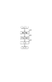
図10は、凹面回折格子と受光センサ(ラインセンサ)を組み合わせたローランド型分光測定装置である。光源によって照らされたサンプルの反射光は、スリットを通過し分光測定装置に入射する。次に、凹面回折格子に入射した光は分光し反射する。さらに、反射した光は、凹面回折格子上の曲率半径を直径とする円上に結像する。そして、結像位置に配置したラインセンサを用いて、分光した光の強度を画素値として取得することで、入射光の分光情報を測定することができる。このような構成の分光測定装置において、入射光の波長とラインセンサ上の画素位置との対応関係を正確に求めなければ、精度良く分光情報を測定することはできない。 FIG. 10 shows a Roland-type spectroscopic measurement device combining a concave diffraction grating and a light receiving sensor (line sensor). The reflected light of the sample illuminated by the light source passes through the slit and enters the spectrometer. Next, the light incident on the concave diffraction grating is dispersed and reflected. Further, the reflected light forms an image on a circle having a radius of curvature on the concave diffraction grating. Then, the spectral information of the incident light can be measured by acquiring the intensity of the dispersed light as a pixel value using a line sensor arranged at the imaging position. In the spectroscopic measurement apparatus having such a configuration, spectral information cannot be accurately measured unless the correspondence between the wavelength of incident light and the pixel position on the line sensor is accurately obtained.
上記のような構成の分光測定装置では、次の二つの特性によって、画素位置と波長との対応関係が非線形になってしまう。第一に、光学的に分光した光は円周上に結像するが、ラインセンサは平面であることが一般的であるため、本来結像すべき位置と、ラインセンサ上での位置が異なってしまう。第二に、凹面回折格子の光学特性によって、分光した光はボケてしまう。加えて、ボケ特性は波長によって異なる。このような二つの特性から、画素位置と波長との対応関係は非線形となる。 In the spectroscopic measurement apparatus configured as described above, the correspondence between the pixel position and the wavelength becomes nonlinear due to the following two characteristics. First, the optically dispersed light forms an image on the circumference, but since the line sensor is generally a flat surface, the position on which the image should be originally formed differs from the position on the line sensor. End up. Secondly, the dispersed light is blurred due to the optical characteristics of the concave diffraction grating. In addition, the blur characteristic varies depending on the wavelength. From these two characteristics, the correspondence between the pixel position and the wavelength is nonlinear.
そこで、このような非線形な画素位置と波長との対応関係を算出する手法として、単波長を分光測定装置に入射し、モノクロメータを用いて画素ごとに対応関係を導き出すことが一般的である。しかしながら、モノクロメータを要する分光測定装置をプリンタなどの機器に組み込むことは現実的でない。 Therefore, as a method for calculating the correspondence between such a non-linear pixel position and wavelength, it is common to enter a single wavelength into a spectroscopic measurement apparatus and derive a correspondence for each pixel using a monochromator. However, it is not realistic to incorporate a spectroscopic measurement device that requires a monochromator into a device such as a printer.
また、簡易的な校正方法として、次のような手法が考えられる。まず、複数の輝線を持つ光源からの光を分光測定装置に入射し、輝線の波長と対応する検出位置を算出する。そして、複数の輝線の波長と対応する検出位置との組から回帰曲線を生成することによって、画素位置と波長との対応関係を導き出すことが知られている(例えば、特許文献1)。なお、本明細書中では、特定の輝線に対応するセンサ上での画素位置を検出位置という。 As a simple calibration method, the following method can be considered. First, light from a light source having a plurality of bright lines is incident on the spectroscopic measurement apparatus, and a detection position corresponding to the wavelength of the bright line is calculated. It is known that a regression curve is generated from a set of a plurality of emission line wavelengths and corresponding detection positions to derive a correspondence relationship between the pixel position and the wavelength (for example, Patent Document 1). In the present specification, a pixel position on a sensor corresponding to a specific bright line is referred to as a detection position.
特許文献1に記載されている手法の場合、画素位置と波長との対応関係を求めるためには、予め輝線が結像する検出位置の範囲を特定する必要がある。しかし、分光測定装置においては、経時変化や温度変化などによって、波長とセンサ上での検出位置が変化する場合があり、予め特定されてある範囲内では検出位置と波長との対応関係を適切に取得することができない場合がある。その結果、正しく分光測定装置の校正を行うことができない。 In the case of the method described in Patent Document 1, in order to obtain the correspondence between the pixel position and the wavelength, it is necessary to specify the range of the detection position where the bright line forms an image in advance. However, in a spectroscopic measurement device, the wavelength and the detection position on the sensor may change due to changes over time, temperature changes, etc., and the correspondence between the detection position and the wavelength is appropriately set within a predetermined range. You may not be able to get it. As a result, the spectrometer cannot be correctly calibrated.
上記課題を解決するために、本発明の分光測定装置の校正装置は、分光測定装置のセンサにおける画素位置と波長とを対応付けることにより、前記センサの校正を行う校正装置であって、予め設定された光源を分光した入射光を前記分光測定装置のセンサにより測定して得られた測定データを取得する測定データ取得手段と、前記測定データにおける極値を探索する探索範囲を設定する設定手段と、前記設定手段により設定された探索範囲において前記測定データの極値を探索する探索手段と、前記探索手段によって探索された極値が正しいか否かを判定する判定手段と、前記判定手段の結果に応じて、前記探索範囲を更新する更新手段と、前記設定手段、前記探索手段、前記判定手段、前記更新手段により探索された前記測定データの極値に対応する画素位置を取得する取得手段と、前記取得手段により取得された極値に対応する画素位置と前記光源の波長との対応関係に基づいて、前記分光測定装置の校正を行う校正手段と、を有する。 In order to solve the above problems, a calibration apparatus for a spectroscopic measurement apparatus according to the present invention is a calibration apparatus that calibrates the sensor by associating a pixel position and a wavelength in the sensor of the spectroscopic measurement apparatus. Measurement data acquisition means for acquiring measurement data obtained by measuring incident light obtained by splitting the incident light source with a sensor of the spectrometer, setting means for setting a search range for searching extreme values in the measurement data, A search means for searching for an extreme value of the measurement data in a search range set by the setting means, a determination means for determining whether the extreme value searched by the search means is correct, and a result of the determination means In response, updating means for updating the search range, the setting means, the searching means, the determining means, and the extreme value of the measurement data searched by the updating means An acquisition unit that acquires a corresponding pixel position; a calibration unit that calibrates the spectroscopic measurement device based on the correspondence between the pixel position corresponding to the extreme value acquired by the acquisition unit and the wavelength of the light source; Have
本発明の分光測定装置の校正装置、校正方法、及びプログラムによれば、経時変化や温度変化などによって波長と検出位置との対応関係が変化した場合であっても、検出位置と波長との対応関係を適切に取得することができる。その結果、正しく分光測定装置の校正を行うことが可能となる。 According to the calibration apparatus, calibration method, and program of the spectroscopic measurement apparatus of the present invention, the correspondence between the detection position and the wavelength can be obtained even when the correspondence between the wavelength and the detection position is changed due to a change with time or a temperature change. Relationships can be acquired appropriately. As a result, the spectroscopic measurement apparatus can be correctly calibrated.
<実施形態1>
本実施形態1は、まず基準白色板に対する測定データから極値(頂点)を算出する。ここで極値とは、画素位置(入力)―画素値(出力)との関係における極値である。そして、探索した極値が正しいかどうかを判定し、誤っている場合には、探索に使用したパラメータ(探索範囲やフィティング次元数)を変更し、再探索することで、正しい極値を算出するものである。
<Embodiment 1>
In the first embodiment, an extreme value (vertex) is first calculated from measurement data with respect to a reference white plate. Here, the extreme value is an extreme value in the relationship of pixel position (input) −pixel value (output). Then, it is determined whether or not the searched extreme value is correct. If it is incorrect, the parameters (search range and number of fitting dimensions) used for the search are changed and re-searched to calculate the correct extreme value. To do.
本実施形態の分光測定装置101の構成について、図1のブロック図を用いて説明する。光源102から照射された光はサンプル116で反射される。その反射光は、スリット103で光線幅が制限され、分光測定装置101に入射光として入射される。なお、スリット103は分光測定装置101の一部である。凹面回折格子104はスリット103から入射される光を分光して反射する。受光センサ105(ラインセンサ105)は凹面回折格子104にて分光、反射した光を受光する。制御処理部106は光源102や受光センサ105の動作制御や受光センサ105にて受光した分光データの取り込み、さらに、処理を行う。Central−Processing−Unit(CPU)107は制御処理部106内の各ユニットを制御する。Read−Only−Memory(ROM)108は変更を必要としないプログラムやパラメータなどを格納する記憶部である。Random−Access―Memory(RAM)109は外部装置から供給されるプログラムやデータを一時記憶する。また、RAM109は、CPU107による各種制御や計算に必要とされるワークメモリとして機能する。光源コントローラ110は、光源102の光量、発光タイミングや発光時間を制御するための光源コントローラである。受光センサコントローラ111は、受光センサ105を制御する。A/D変換部112は、受光センサコントローラ111を用いて受光センサ105から取得(撮像)したアナログ信号値をデジタル信号値に変換する。信号処理部113はA/D変換部112にて変換されたデジタル信号値に対して各種の処理する。外部インターフェース114は、信号処理部113にて処理されたデジタル信号値などを外部に出力したり、外部からの制御信号を入力する。システムバス115は、制御処理部106の各ユニット間でのデータ通信可能とする。センサ校正処理(センサキャリブレーション処理)を行う際は、サンプル116として基準白色板が用いられる。
The configuration of the
<全体処理の流れ>
本実施形態1の分光測定装置101における処理の流れについて、図2及び図3のフローチャートを用いて詳細に説明する。
まず、ステップS201では、分光測定装置101の電源を入れるなど測定するための準備を行う。ステップS202では、分光測定装置101のキャリブレーション処理(校正処理)を行う(詳細は後述する)。ステップS203では、校正処理された分光測定装置101を用いて測定対象の分光データの測定を行う。
<Overall process flow>
The flow of processing in the
First, in step S201, preparations for measurement are made, such as turning on the power of the
<校正処理>
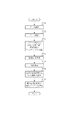
次に、図3を用いて、ステップS202の校正処理について詳細に説明する。ステップS301では、CPU107は、光源コントローラ110を駆動させ、光源102を点灯させる。さらに、CPU107は、受光センサコントローラ111を駆動させ、基準白色板116の分光データを測定する。測定したデータは、A/D変換部112や信号処理部113により後述する各種処理を実行しやすいようなデジタルデータに変換され、RAM109に格納される。ステップS302では、CPU107は、ROM108から、波長と検出位置との対応関係や探索範囲、及び、フィッティング次元数などの初期パラメータ(詳細は後述する)を読み込み、RAM109に格納する。ステップS303では、CPU107は、ステップS302にて読み込んだ初期パラメータに基づいて画素位置における画素値の分布の極値の探索を探索範囲内で行う(詳細は後述する)。ステップS304では、CPU107は、ステップS303にて探索した極値の判定が所定の条件を満たすか否かの判断を行う(詳細は後述する)。正しい場合には、探索された検出位置と波長との対応関係をRAM109に記憶し、ステップS306に進む。誤っている場合にはステップS305に進む。ステップS305では、CPU107は、ROM108に格納している次の候補パラメータを読み込み、RAM109に格納し、ステップS303に戻る(パラメータの更新についての詳細は後述する)。そして、再度ステップS303にて、更新されたパラメータに基づき、極値を再探索(再取得)をし、ステップS304以下の処理を継続する。
<Calibration process>
Next, the calibration process in step S202 will be described in detail with reference to FIG. In step S <b> 301, the CPU 107 drives the light source controller 110 to turn on the
ステップS306では、CPU107は、すべての極値に対して探索したかどうかを判定する。すべての極値に対して探索した場合には、ステップS308に進み、そうでない場合には、ステップS307に進む。ステップS307では、探索する極値の更新を行いステップS203に戻る。ステップS303からステップS307までの処理を繰り返し、すべての極値について、検出位置を取得する。ステップS308では、CPU107は、ステップS303〜S307にて取得した極値に対応する波長と検出位置との関係から回帰曲線を算出する。この回帰曲線は、波長とラインセンサ105の検出位置との対応関係を示す。最後に、ステップS309では、CPU107は、ステップS308にて算出した回帰曲線を基に画素位置と波長との対応テーブルを生成し、RAM109に格納する。RAM109に格納された対応テーブルにより分光測定装置101の校正がなされる。
In step S306, the CPU 107 determines whether all extreme values have been searched. If all extreme values have been searched, the process proceeds to step S308. If not, the process proceeds to step S307. In step S307, the extreme values to be searched are updated, and the process returns to step S203. The processing from step S303 to step S307 is repeated, and detection positions are acquired for all extreme values. In step S308, the CPU 107 calculates a regression curve from the relationship between the wavelength corresponding to the extreme value acquired in steps S303 to S307 and the detection position. This regression curve shows the correspondence between the wavelength and the detection position of the line sensor 105. Finally, in step S309, the CPU 107 generates a correspondence table between pixel positions and wavelengths based on the regression curve calculated in step S308, and stores it in the RAM 109. The
<パラメータ>
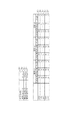
図4(a)(b)に本実施形態におけるパラメータの一例を示す。図4(a)(b)に記載されているパラメータは、ROM108やRAM109に記憶されている。本実施形態において必要なパラメータは以下の通りである。
・探索する極値の総数(401)
・初期状態における極値の波長(402〜404)
・極値を算出するためのn次元多項式の初期のフィッティング次元数(405)
・フィッティング判定の閾値(406)
・それぞれの極値の探索範囲(407〜410)
なお、極値の波長は入射光の輝線の波長に対応している。また、重回帰分析によって、多項式近似を行い、それによって、極値を求める場合には、少なくとも(フィッティング次元数+1)個の画素数が必要となる。一般的に、受光センサの出力にはノイズが含まれている。そのため、あまりにもフィッティング次元数を高く設定してしまうと、ノイズによる変動に対してフィッティングしてしまう。結果、誤った極値を算出することになる。そこで、できるだけ小さいフィッティング次元数を用いることが望ましい。
<Parameter>
4A and 4B show examples of parameters in the present embodiment. The parameters described in FIGS. 4A and 4B are stored in the ROM 108 and the RAM 109. The necessary parameters in this embodiment are as follows.
-Total number of extreme points to search (401)
・ Extreme wavelength in the initial state (402 to 404)
The initial number of fitting dimensions of the n-dimensional polynomial for calculating extreme values (405)
・ Fitting determination threshold (406)
-Search range of each extreme value (407-410)
Note that the extreme wavelength corresponds to the wavelength of the emission line of the incident light. In addition, when performing polynomial approximation by multiple regression analysis and thereby obtaining extreme values, at least (fitting dimension number + 1) number of pixels is required. Generally, the output of the light receiving sensor includes noise. For this reason, if the fitting dimension number is set too high, the fitting is performed with respect to fluctuation due to noise. As a result, an incorrect extreme value is calculated. Therefore, it is desirable to use a fitting dimension number as small as possible.
<極値探索>
ステップS303の極値の算出方法について詳細に説明する。例えば、2次元の多項式近似を用いて極値を近似する場合、探索範囲の検出位置をx0,x1,x2…、対応する基準白色板116を測定した際の出力値(画素値)をy0,y1,y2,…、2次元多項式の係数をa,b,cとする。最小二乗法を用いると係数a,b,cは(数式1)のようにして求めることができる。
<Extreme search>
The extreme value calculation method in step S303 will be described in detail. For example, when the extreme value is approximated using a two-dimensional polynomial approximation, the detection position of the search range is x0, x1, x2,..., And the output value (pixel value) when the corresponding reference white plate 116 is measured is y0, y1, y2,... are two-dimensional polynomial coefficients a, b, c. When the least square method is used, the coefficients a, b, and c can be obtained as shown in (Formula 1).

(数式1)によって求められた係数a,b,cを用いて、極値を取る検出位置(極値位置)を(数式2)によって求める。
極値位置=−b/2a ・・・(数式2)
2次元より大きな次元の多項式の場合についても同様に幾何的、代数的に極値を求める。
Using the coefficients a, b, and c obtained by (Equation 1), a detection position (extreme value position) at which an extreme value is obtained is obtained by (Equation 2).
Extreme value position = −b / 2a (Expression 2)
Similarly, in the case of a polynomial having a dimension larger than two dimensions, the extreme value is obtained geometrically and algebraically.
<極値の判定>
ステップS304の極値の判定について、図5、及び図6を用いて詳細に説明する。
<Determination of extreme values>
The determination of the extreme value in step S304 will be described in detail with reference to FIGS.
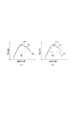
図5(a)は、極値の探索が正しい場合を示している。基準白色板の測定値501に対して、探索範囲502内で、多項式近似503を行い、極値位置504を上記の方法で算出する。この場合、基準白色板の測定値の極値と多項式近似から求めた極値位置504が一致している(又は許容される誤差の範囲内にある)。一方、図5(b)は、極値の探索が誤っている場合を示している。上記と同様に、基準白色板の測定値505に対して、探索範囲506で多項式近似507を行い極値位置508を算出する。この場合、基準白色板の測定値505の極値と、多項式近似から求めた極値位置508は一致しない。これは、探索範囲506が正しくないためである。この判定方法は、算出した極値位置504、508が、探索範囲502,506内にあるかどうかを判定すれば良い。つまり、極値位置が、探索範囲内にあれば、正しい極値であり、探索範囲の境界、又は探索範囲外にあれば、誤った極値となる。
FIG. 5A shows a case where the extreme value search is correct. A
次に、図6(a)も、極値の探索が正しい場合を示している。基準白色板の測定値601に対して、探索範囲602内で、多項式近似603を行い、極値位置604を上記の方法で算出する。この場合、基準白色板の測定値の極値と多項式近似から求めた極値位置604が一致している(又は許容される誤差の範囲内にある)。一方、図6(b)は、極値の探索が誤っている場合を示している。上記と同様に、基準白色板の測定値605に対して、探索範囲606で多項式近似607を行い、極値位置608を算出する。この場合、基準白色板の測定値605の極値と、多項式近似から求めた極値位置608は一致しない。これは、上記の探索範囲内に極値があるにも係わらず、探索が誤っている場合である。この場合は、近似対象が左右非対処な形状に対して、多項式近似時のフィッティング次元数が異なるために、探索が失敗している。そこで、(数式3)のように多項式近似した結果と基準白色板の測定値との最小二乗誤差値をとり、フィッティング判定の閾値406と比較することにより、誤った極値であるか否かを判断する。本実施形態では、最小二乗誤差値が閾値406以上であった場合、誤った極値であると判定する。
Next, FIG. 6A also shows a case where the extreme value search is correct. A
<パラメータの更新>
ステップS305のパラメータ更新について説明する。
<Parameter update>
The parameter update in step S305 will be described.
上述のように、ステップS304にて、正しくない極値と判定された場合(所定の条件を満たした場合)は、以下の二通りある。
(a)極値が探索範囲の境界、又は探索範囲外にある
(b)多項式近似時のフィッティング次元数が不適切である
そこで、上述の二通りの場合、及びその組合せにおけるパラメータの更新を説明する。
As described above, when it is determined in step S304 that the extreme value is not correct (when a predetermined condition is satisfied), there are the following two types.
(A) Extreme value is outside the search range boundary or outside the search range (b) The fitting dimension number at the time of polynomial approximation is inappropriate. Therefore, the update of parameters in the above two cases and combinations thereof will be described. To do.
(a)探索範囲の更新
極値が探索範囲の境界、又は探索範囲外にあり、正しくない極値と判定された場合、図4の408〜410のように探索範囲をずらす。図4の例では、最初に探索範囲1(407)で見つからなかった場合には、探索範囲2(408)のように左に4画素シフトさせる。また、更に見つからない場合には、探索範囲3(409)のように右にシフトさせる。それでも見つからない場合には、探索範囲4(410)のように探索範囲を広げて探索を行う。
なお、多項式近似のフィッティングの精度を向上させるためには、極値の探索範囲は、探索範囲を狭くすることが望ましい。極値と離れた画素値のデータにより極値付近のデータの精度が悪くなることを回避するためである。
この探索範囲のパラメータの更新は、この例に限定されるものではないのは言うまでもない。センサの温度特性などに応じて予め極値が移動しやすい方向に探索範囲を選択するようにすれば、探索時間などの短縮を行える。
(A) Search range update When the extreme value is outside the search range or outside the search range and is determined to be an incorrect extreme value, the search range is shifted as indicated by reference numerals 408 to 410 in FIG. In the example of FIG. 4, when it is not found in the search range 1 (407) for the first time, it is shifted to the left by 4 pixels as in the search range 2 (408). If it is not found further, it is shifted to the right as shown in search range 3 (409). If still not found, the search range is expanded as in the search range 4 (410).
In order to improve the accuracy of polynomial approximation fitting, it is desirable that the extreme value search range is narrowed. This is in order to avoid the deterioration of the accuracy of data in the vicinity of the extreme value due to the pixel value data separated from the extreme value.
It goes without saying that the search range parameter update is not limited to this example. If the search range is selected in the direction in which the extreme value easily moves in accordance with the temperature characteristics of the sensor, the search time can be shortened.
(b)フィッティング次元数の更新
多項式近似のフィッティング次元数が不適切であり、正しくない極値と判定された場合、フィッティング次元数を上げる。例えば、図4の例では、最初にフィッティング次元数を2として探索するが、最小二乗誤差誤差がフィッティング判定閾値406以上である場合に、フィッティング次元数を3にする。
ノイズによるフィッティングの影響を軽減するために、フィッティング次元数は、なるべく小さいほど良い。本実施形態によれば、低い次元数でフィッティングを行い、所定の条件を満たした場合に限り、次元数を上げることからノイズの影響を極力排除したフィッティングを可能にしている。
(B) Updating the fitting dimension number When the fitting dimension number of the polynomial approximation is inappropriate and it is determined as an incorrect extreme value, the fitting dimension number is increased. For example, in the example of FIG. 4, the number of fitting dimensions is first searched as 2, but when the least square error is equal to or greater than the fitting determination threshold 406, the number of fitting dimensions is set to 3.
In order to reduce the effect of fitting due to noise, the fitting dimension is preferably as small as possible. According to the present embodiment, fitting is performed with a low number of dimensions, and the number of dimensions is increased only when a predetermined condition is satisfied.
(c)探索範囲、及びフィッティング次元数の更新
図4(c)に記載されているように、探索範囲、及びフィッティング次元数の両者を組み合わせた形で更新することも考えられる。この例では、極値(1)について、最初に探索パラメータ1でフィッティングを実行する。このフィッティングの際のフィッティング次元数は2である。この際の極値位置が、探索範囲境界、又は探索範囲外である場合、或いは、最小二乗誤差がフィッティング判定閾値以上である場合は、探索パラメータを探索パラメータ2に更新する。
この実施形態によれば、探索範囲とフィッティング次元数の両者を考慮したフィッティングを行うことが可能となり、より精度の高いフィッティングを実現することができる。
(C) Update of Search Range and Fitting Dimension Number As shown in FIG. 4C, updating the search range and the fitting dimension number in combination is also conceivable. In this example, the extreme value (1) is first fitted with the search parameter 1. The number of fitting dimensions at the time of this fitting is 2. If the extreme value position at this time is outside the search range boundary or the search range, or if the least square error is greater than or equal to the fitting determination threshold, the search parameter is updated to search
According to this embodiment, it is possible to perform fitting in consideration of both the search range and the number of fitting dimensions, and it is possible to realize fitting with higher accuracy.
<本実施形態の効果>
本実施形態によれば、波長と検出位置との対応関係の校正を行うことができる。そして、本実施形態では、探索範囲やフィッティング次元数などを予めパラメータとして保持しておくため、探索範囲や次元数を逐一決定しながら最適化する手法に比べて高速な処理が可能となる。また、本実施形態では、探索範囲を狭めてフィッティングすることから精度の高いフィッティングを行うことができる。更に、本実施形態では、なるべく低い次元の多項式でフィッティングをすることから、ノイズの影響を受けないフィッティングを可能としている。
<Effect of this embodiment>
According to the present embodiment, the correspondence relationship between the wavelength and the detection position can be calibrated. In this embodiment, since the search range, the number of fitting dimensions, and the like are stored as parameters in advance, high-speed processing can be performed as compared with the method of optimizing while determining the search range and the number of dimensions one by one. Moreover, in this embodiment, since fitting is performed with a narrow search range, highly accurate fitting can be performed. Furthermore, in the present embodiment, since fitting is performed with a polynomial having as low a dimension as possible, fitting that is not affected by noise is possible.
<実施形態2>
本実施形態2の概要について述べる。
本実施形態2では、まず光源を光らせない状態の画素値のダークデータを取得する。そして、取得したダークデータを解析することで、分光測定装置の状態を取得し、パラメータ(探索範囲やフィティング次元数)を変更することで、精度良く極値を算出するものである。
本実施形態2の分光測定装置の構成は、実施形態1のブロック図と等しいため省略する。
<
An outline of the second embodiment will be described.
In the second embodiment, first, dark data of pixel values in a state where the light source is not illuminated is acquired. Then, by analyzing the acquired dark data, the state of the spectroscopic measurement apparatus is acquired, and the extreme values are calculated with high accuracy by changing the parameters (search range and number of fitting dimensions).
Since the configuration of the spectroscopic measurement apparatus according to the second embodiment is the same as the block diagram of the first embodiment, the description thereof is omitted.
<全体処理の流れ>
本実施形態2の分光測定装置における全体処理の流れは実施形態1と等しいため省略する。
<Overall process flow>
The overall processing flow in the spectroscopic measurement apparatus according to the second embodiment is the same as that in the first embodiment, and is therefore omitted.
<校正処理>
図2のステップS202の校正処理について、実施形態1と異なるため、図7のフローチャートを用いて詳細に説明する。
まず、ステップS701では、CPU107は、受光センサコントローラ111を駆動させ、ダークデータを取得する。ステップS702では、CPU107は、ステップS701にて取得したダークデータを解析する(詳細は後述する)。ステップS703では、CPU107は、ステップS702にて解析した結果に基づいて、パラメータを設定する(詳細は後述する)。ステップS704では、CPU107は光源コントローラ110を駆動させ、光源102を点灯させる。さらに、受光センサコントローラ111を駆動させ、基準白色板116の分光データを測定する。ステップS705では、CPU107は、ステップS703にてパラメータに基づいて、ステップS704で取得した基準白色板の分光データから実施形態1にステップS303と同様の処理を用いて極値を探索する。ステップS706では、CPU107は、ステップS705にて取得した極値と対応する波長の関係から回帰曲線を生成する。最後に、ステップS707では、CPU107は、ステップS706にて算出した回帰曲線に基づいて画素位置と波長との対応テーブルを算出し、RAM109に格納する。
<Calibration process>
The calibration process in step S202 in FIG. 2 is different from that in the first embodiment, and will be described in detail with reference to the flowchart in FIG.
First, in step S701, the CPU 107 drives the light receiving sensor controller 111 to acquire dark data. In step S702, the CPU 107 analyzes the dark data acquired in step S701 (details will be described later). In step S703, the CPU 107 sets parameters based on the result analyzed in step S702 (details will be described later). In step S <b> 704, the CPU 107 drives the light source controller 110 to turn on the
<ダーク解析>
ステップS702のダーク解析について詳細に説明する。本実施形態2における分光測定装置101の波長と検出位置との対応関係を変動させる要因の一つとして、分光測定装置自体の温度による変動がある。例えば、温度変動によって、機体が膨張伸縮するということが考えられる。その結果、波長と検出位置との対応関係が変化する。図8は、ダークデータの受光センサの平均出力値(暗電流成分)と、温度との対応関係を示している。図8が示すように、ダークデータの平均出力値によって、受光センサの温度を取得する。
<Dark analysis>
The dark analysis in step S702 will be described in detail. One factor that causes the correspondence between the wavelength of the
<パラメータの設定>
図9にステップS703のパラメータの一例について示す。本実施形態2において必要なパラメータは、探索極値数(901)、極値の波長(902〜904)、及び、センサ温度に対応する探索範囲とフィッティング次元数(905〜909)である。ステップS702にて、取得した受光センサの温度に対応する探索範囲とフィッティング次元数をRAM109にセットする。
<Parameter settings>
FIG. 9 shows an example of the parameters in step S703. Necessary parameters in the second embodiment are the number of search extreme values (901), the wavelength of extreme values (902 to 904), and the search range and the number of fitting dimensions (905 to 909) corresponding to the sensor temperature. In step S702, the search range and the fitting dimension number corresponding to the acquired temperature of the light receiving sensor are set in the RAM 109.
<実施形態1との組合せについて>
本実施形態2は、実施形態1と組み合わせて実施することも可能である。この場合、最初の探索範囲を本実施形態2の手法を用いて取得する。そして、極値が探索範囲の境界、又は探索範囲外に存在する場合、或いは、最小二乗誤差がフィッティング判定閾値以上である場合は、実施形態1の手法に従って、探索範囲、又はフィッティング次元数を更新する。
<Combination with Embodiment 1>
The second embodiment can be implemented in combination with the first embodiment. In this case, the first search range is acquired using the method of the second embodiment. If the extreme value exists outside the search range boundary or the search range, or if the least square error is equal to or greater than the fitting determination threshold, the search range or the number of fitting dimensions is updated according to the method of the first embodiment. To do.
<実施形態2の効果>
本実施形態2では、分光測定装置の温度状況に応じて極値の探索範囲を切り替える。これにより、分光測定装置の温度状況が変化したとしても、波長と画素の対応関係を精度良く算出することができる。
<Effect of
In the second embodiment, the extreme value search range is switched according to the temperature state of the spectroscopic measurement apparatus. Thereby, even if the temperature condition of the spectroscopic measurement device changes, the correspondence between the wavelength and the pixel can be calculated with high accuracy.
<実施形態3>
また、本発明は、以下の処理を実行することによっても実現される。即ち、上述した実施形態の機能を実現するソフトウェア(プログラム)を、ネットワーク又は各種記憶媒体を介してシステム或いは装置に供給し、そのシステム或いは装置のコンピュータ(またはCPUやMPU等)がプログラムを読み出して実行する処理である。
<
The present invention can also be realized by executing the following processing. That is, software (program) that realizes the functions of the above-described embodiments is supplied to a system or apparatus via a network or various storage media, and a computer (or CPU, MPU, or the like) of the system or apparatus reads the program. It is a process to be executed.
Claims (11)
予め設定された光源を分光した入射光を前記分光測定装置のセンサにより測定して得られた測定データを取得する測定データ取得手段と、
前記測定データにおける極値を探索する探索範囲を設定する設定手段と、
前記設定手段により設定された探索範囲において前記測定データの極値を探索する探索手段と、
前記探索手段によって探索された極値が正しいか否かを判定する判定手段と、
前記判定手段の結果に応じて、前記探索範囲を更新する更新手段と、
前記設定手段、前記探索手段、前記判定手段、前記更新手段により探索された前記測定データの極値に対応する画素位置を取得する取得手段と、
前記取得手段により取得された極値に対応する画素位置と前記光源の波長との対応関係に基づいて、前記分光測定装置の校正を行う校正手段と、
を有することを特徴とする校正装置。 A calibration device that calibrates the sensor by associating the pixel position and wavelength in the sensor of the spectroscopic measurement device,
Measurement data acquisition means for acquiring measurement data obtained by measuring incident light obtained by separating a preset light source with a sensor of the spectrometer,
Setting means for setting a search range for searching for extreme values in the measurement data;
Search means for searching for extreme values of the measurement data in the search range set by the setting means;
Determination means for determining whether or not the extreme value searched by the search means is correct;
Updating means for updating the search range according to the result of the determination means;
Acquisition means for acquiring a pixel position corresponding to an extreme value of the measurement data searched by the setting means, the search means, the determination means, and the update means;
Calibration means for calibrating the spectroscopic measurement device based on the correspondence between the pixel position corresponding to the extreme value acquired by the acquisition means and the wavelength of the light source;
A calibration apparatus comprising:
更に前記入射光を撮像するセンサを有する分光測定装置。 Each means of the calibration device according to claim 1,
Further, a spectroscopic measurement apparatus having a sensor for imaging the incident light.
予め設定された光源を分光した入射光を前記分光測定装置のセンサにより測定して得られた測定データを取得する測定データ取得工程、
前記測定データにおける極値を探索する探索範囲を設定する設定工程と、
前記設定工程により設定された探索範囲において前記測定データの極値を探索する探索工程と、
前記探索工程によって探索された極値が正しいか否かを判定する判定工程と、
前記判定工程の結果に応じて、前記探索範囲を更新する更新工程と、
前記設定工程、前記探索工程、前記判定工程、前記更新工程により探索された前記測定データの極値に対応する画素位置を取得する取得工程と、前記取得工程により取得された極値に対応する画素位置と前記光源の波長との対応関係に基づいて、前記分光測定装置の校正を行う校正工程と、
を有する校正方法。 A calibration method for calibrating the sensor by associating the pixel position and wavelength in the sensor of the spectroscopic measurement device,
A measurement data acquisition step of acquiring measurement data obtained by measuring incident light obtained by dispersing a preset light source with a sensor of the spectroscopic measurement device;
A setting step for setting a search range for searching for extreme values in the measurement data;
A search step for searching for extreme values of the measurement data in the search range set by the setting step;
A determination step of determining whether or not the extreme value searched by the search step is correct;
An update step of updating the search range according to a result of the determination step;
An acquisition step of acquiring a pixel position corresponding to the extreme value of the measurement data searched by the setting step, the search step, the determination step, and the update step, and a pixel corresponding to the extreme value acquired by the acquisition step Based on the correspondence between the position and the wavelength of the light source, a calibration step for calibrating the spectrometer,
A calibration method.
Priority Applications (2)
| Application Number | Priority Date | Filing Date | Title |
|---|---|---|---|
| JP2009273888A JP5709372B2 (en) | 2009-12-01 | 2009-12-01 | Calibration means, calibration method, and program |
| US12/956,910 US8564771B2 (en) | 2009-12-01 | 2010-11-30 | Calibration apparatus and calibration method |
Applications Claiming Priority (1)
| Application Number | Priority Date | Filing Date | Title |
|---|---|---|---|
| JP2009273888A JP5709372B2 (en) | 2009-12-01 | 2009-12-01 | Calibration means, calibration method, and program |
Publications (3)
| Publication Number | Publication Date |
|---|---|
| JP2011117777A JP2011117777A (en) | 2011-06-16 |
| JP2011117777A5 JP2011117777A5 (en) | 2012-12-20 |
| JP5709372B2 true JP5709372B2 (en) | 2015-04-30 |
Family
ID=44068654
Family Applications (1)
| Application Number | Title | Priority Date | Filing Date |
|---|---|---|---|
| JP2009273888A Expired - Fee Related JP5709372B2 (en) | 2009-12-01 | 2009-12-01 | Calibration means, calibration method, and program |
Country Status (2)
| Country | Link |
|---|---|
| US (1) | US8564771B2 (en) |
| JP (1) | JP5709372B2 (en) |
Families Citing this family (8)
| Publication number | Priority date | Publication date | Assignee | Title |
|---|---|---|---|---|
| CN103115878B (en) * | 2012-12-29 | 2016-08-03 | 聚光科技(杭州)股份有限公司 | Correct method and the application of spectral drift |
| EP2975372A4 (en) | 2013-03-12 | 2016-12-21 | Univ Osaka | Light wavelength measurement method and light wavelength measurement apparatus |
| JP6180954B2 (en) * | 2014-02-05 | 2017-08-16 | 浜松ホトニクス株式会社 | Spectrometer and method of manufacturing the spectrometer |
| JP2017053903A (en) * | 2015-09-07 | 2017-03-16 | キヤノン株式会社 | Image forming apparatus |
| CN105424185B (en) * | 2015-11-04 | 2017-08-11 | 清华大学 | A kind of computer assisted all band spectrometer wavelength calibration method |
| CN108106726A (en) * | 2017-12-14 | 2018-06-01 | 中国科学院长春光学精密机械与物理研究所 | A kind of spectrometer ambient noise suppression system |
| CN110913665B (en) * | 2019-12-09 | 2021-02-26 | 中国科学院合肥物质科学研究院 | Precise temperature control system of satellite-borne detector |
| JP2022147223A (en) | 2021-03-23 | 2022-10-06 | 大塚電子株式会社 | Optical measurement system, optical measurement method and measurement program |
Family Cites Families (9)
| Publication number | Priority date | Publication date | Assignee | Title |
|---|---|---|---|---|
| JPH03144321A (en) * | 1989-10-30 | 1991-06-19 | Mitsui Petrochem Ind Ltd | Measuring method for wavelength of laser oscillation |
| JP2689707B2 (en) | 1990-08-28 | 1997-12-10 | 松下電器産業株式会社 | Spectrometer with wavelength calibration function |
| JPH10332485A (en) * | 1997-05-27 | 1998-12-18 | Shimadzu Corp | Data processing method for emission spectrochemical analysis device |
| JP3925301B2 (en) * | 2001-07-12 | 2007-06-06 | コニカミノルタセンシング株式会社 | Spectral characteristic measuring apparatus and wavelength shift correction method for spectral sensitivity of the same |
| US6974973B2 (en) * | 2002-11-08 | 2005-12-13 | Micron Technology, Inc. | Apparatus for determining temperature of an active pixel imager and correcting temperature induced variations in an imager |
| US20050267689A1 (en) * | 2003-07-07 | 2005-12-01 | Maxim Tsypin | Method to automatically identify peak and monoisotopic peaks in mass spectral data for biomolecular applications |
| JP4660694B2 (en) * | 2005-06-28 | 2011-03-30 | コニカミノルタセンシング株式会社 | Spectrometer wavelength calibration method and spectrometer |
| US20090002703A1 (en) * | 2006-08-16 | 2009-01-01 | Craig Edward Parman | Methods and systems for quantifying isobaric labels and peptides |
| EP1998155A1 (en) * | 2007-05-30 | 2008-12-03 | Roche Diagnostics GmbH | Method for wavelength calibration of a spectrometer |
-
2009
- 2009-12-01 JP JP2009273888A patent/JP5709372B2/en not_active Expired - Fee Related
-
2010
- 2010-11-30 US US12/956,910 patent/US8564771B2/en not_active Expired - Fee Related
Also Published As
| Publication number | Publication date |
|---|---|
| US8564771B2 (en) | 2013-10-22 |
| JP2011117777A (en) | 2011-06-16 |
| US20110128542A1 (en) | 2011-06-02 |
Similar Documents
| Publication | Publication Date | Title |
|---|---|---|
| JP5709372B2 (en) | Calibration means, calibration method, and program | |
| US7471391B2 (en) | Method for calibrating spectral characteristics of a spectral analyzer and a spectral analyzer applying said method | |
| JP4323991B2 (en) | Spectral reflectance measuring device, film thickness measuring device, and spectral reflectance measuring method | |
| US11561166B2 (en) | Focusing linear model correction and linear model correction for multivariate calibration model maintenance | |
| JP6102858B2 (en) | Color conversion method, color conversion program, and recording medium | |
| US11530950B2 (en) | Spectral analysis system, mobile device having a spectral analysis system, method for determining a correction function for the imaging correction of a spectrum captured by a spectral analysis system, and computer program | |
| JP2016510408A5 (en) | ||
| US10746599B2 (en) | System and method for spectral interpolation using multiple illumination sources | |
| JP2021047201A (en) | Transfer of calibration model using sparse transfer set | |
| US20080212092A1 (en) | Wavelength displacement correcting system | |
| CN115824048A (en) | Spectrum confocal sensor calibration method, system, equipment and readable storage medium | |
| JP2013124990A (en) | Image processing system and image processing method | |
| KR101637552B1 (en) | Apparatus and Method for compensating irregular image for lense | |
| JP6395455B2 (en) | Inspection device, inspection method, and program | |
| KR20210024468A (en) | Film thickness measurement device and correction method | |
| JP7419029B2 (en) | Linearity correction method for optical measurement device, optical measurement method, and optical measurement device | |
| US11099071B2 (en) | Imaging condition evaluation device and imaging condition evaluation method | |
| JP2010078418A (en) | Spectral measurement apparatus, calibration apparatus, spectral measurement method and calibration method | |
| JP2023504001A (en) | Systems and methods for metrology optimization based on metrology landscape | |
| JP5530337B2 (en) | Bragg wavelength estimation method and apparatus | |
| WO2022153963A1 (en) | Optical characteristics measurement device, wavelength shift correction device, wavelength shift correction method, and program | |
| CN114370944B (en) | Real-time online temperature monitoring method and system with calibration and correction functions | |
| Töpfer et al. | Quality measures for optical probing in optical coordinate metrology | |
| CN117355724A (en) | Film thickness measuring device and film thickness measuring method | |
| CN116265917A (en) | Method for analyzing spectral peaks |
Legal Events
| Date | Code | Title | Description |
|---|---|---|---|
| A521 | Written amendment |
Free format text: JAPANESE INTERMEDIATE CODE: A523 Effective date: 20121106 |
|
| A621 | Written request for application examination |
Free format text: JAPANESE INTERMEDIATE CODE: A621 Effective date: 20121106 |
|
| A977 | Report on retrieval |
Free format text: JAPANESE INTERMEDIATE CODE: A971007 Effective date: 20130830 |
|
| A131 | Notification of reasons for refusal |
Free format text: JAPANESE INTERMEDIATE CODE: A131 Effective date: 20140218 |
|
| A521 | Written amendment |
Free format text: JAPANESE INTERMEDIATE CODE: A523 Effective date: 20140418 |
|
| A131 | Notification of reasons for refusal |
Free format text: JAPANESE INTERMEDIATE CODE: A131 Effective date: 20140916 |
|
| A521 | Written amendment |
Free format text: JAPANESE INTERMEDIATE CODE: A523 Effective date: 20141023 |
|
| A131 | Notification of reasons for refusal |
Free format text: JAPANESE INTERMEDIATE CODE: A131 Effective date: 20141111 |
|
| A521 | Written amendment |
Free format text: JAPANESE INTERMEDIATE CODE: A523 Effective date: 20141226 |
|
| TRDD | Decision of grant or rejection written | ||
| A01 | Written decision to grant a patent or to grant a registration (utility model) |
Free format text: JAPANESE INTERMEDIATE CODE: A01 Effective date: 20150203 |
|
| A61 | First payment of annual fees (during grant procedure) |
Free format text: JAPANESE INTERMEDIATE CODE: A61 Effective date: 20150303 |
|
| R151 | Written notification of patent or utility model registration |
Ref document number: 5709372 Country of ref document: JP Free format text: JAPANESE INTERMEDIATE CODE: R151 |
|
| LAPS | Cancellation because of no payment of annual fees |