JP5709366B2 - System for acoustic transducer for medical ultrasound and method of operating the system - Google Patents
System for acoustic transducer for medical ultrasound and method of operating the system Download PDFInfo
- Publication number
- JP5709366B2 JP5709366B2 JP2009217361A JP2009217361A JP5709366B2 JP 5709366 B2 JP5709366 B2 JP 5709366B2 JP 2009217361 A JP2009217361 A JP 2009217361A JP 2009217361 A JP2009217361 A JP 2009217361A JP 5709366 B2 JP5709366 B2 JP 5709366B2
- Authority
- JP
- Japan
- Prior art keywords
- array
- elements
- twisted
- rotated
- shape memory
- Prior art date
- Legal status (The legal status is an assumption and is not a legal conclusion. Google has not performed a legal analysis and makes no representation as to the accuracy of the status listed.)
- Active
Links
Images






Classifications
-
- H—ELECTRICITY
- H04—ELECTRIC COMMUNICATION TECHNIQUE
- H04R—LOUDSPEAKERS, MICROPHONES, GRAMOPHONE PICK-UPS OR LIKE ACOUSTIC ELECTROMECHANICAL TRANSDUCERS; ELECTRIC HEARING AIDS; PUBLIC ADDRESS SYSTEMS
- H04R17/00—Piezoelectric transducers; Electrostrictive transducers
-
- A—HUMAN NECESSITIES
- A61—MEDICAL OR VETERINARY SCIENCE; HYGIENE
- A61B—DIAGNOSIS; SURGERY; IDENTIFICATION
- A61B8/00—Diagnosis using ultrasonic, sonic or infrasonic waves
- A61B8/12—Diagnosis using ultrasonic, sonic or infrasonic waves in body cavities or body tracts, e.g. by using catheters
-
- A—HUMAN NECESSITIES
- A61—MEDICAL OR VETERINARY SCIENCE; HYGIENE
- A61B—DIAGNOSIS; SURGERY; IDENTIFICATION
- A61B8/00—Diagnosis using ultrasonic, sonic or infrasonic waves
-
- A—HUMAN NECESSITIES
- A61—MEDICAL OR VETERINARY SCIENCE; HYGIENE
- A61B—DIAGNOSIS; SURGERY; IDENTIFICATION
- A61B8/00—Diagnosis using ultrasonic, sonic or infrasonic waves
- A61B8/48—Diagnostic techniques
- A61B8/483—Diagnostic techniques involving the acquisition of a 3D volume of data
-
- A—HUMAN NECESSITIES
- A61—MEDICAL OR VETERINARY SCIENCE; HYGIENE
- A61N—ELECTROTHERAPY; MAGNETOTHERAPY; RADIATION THERAPY; ULTRASOUND THERAPY
- A61N7/00—Ultrasound therapy
-
- B—PERFORMING OPERATIONS; TRANSPORTING
- B06—GENERATING OR TRANSMITTING MECHANICAL VIBRATIONS IN GENERAL
- B06B—METHODS OR APPARATUS FOR GENERATING OR TRANSMITTING MECHANICAL VIBRATIONS OF INFRASONIC, SONIC, OR ULTRASONIC FREQUENCY, e.g. FOR PERFORMING MECHANICAL WORK IN GENERAL
- B06B1/00—Methods or apparatus for generating mechanical vibrations of infrasonic, sonic, or ultrasonic frequency
- B06B1/02—Methods or apparatus for generating mechanical vibrations of infrasonic, sonic, or ultrasonic frequency making use of electrical energy
- B06B1/06—Methods or apparatus for generating mechanical vibrations of infrasonic, sonic, or ultrasonic frequency making use of electrical energy operating with piezoelectric effect or with electrostriction
- B06B1/0607—Methods or apparatus for generating mechanical vibrations of infrasonic, sonic, or ultrasonic frequency making use of electrical energy operating with piezoelectric effect or with electrostriction using multiple elements
- B06B1/0622—Methods or apparatus for generating mechanical vibrations of infrasonic, sonic, or ultrasonic frequency making use of electrical energy operating with piezoelectric effect or with electrostriction using multiple elements on one surface
-
- G—PHYSICS
- G01—MEASURING; TESTING
- G01S—RADIO DIRECTION-FINDING; RADIO NAVIGATION; DETERMINING DISTANCE OR VELOCITY BY USE OF RADIO WAVES; LOCATING OR PRESENCE-DETECTING BY USE OF THE REFLECTION OR RERADIATION OF RADIO WAVES; ANALOGOUS ARRANGEMENTS USING OTHER WAVES
- G01S15/00—Systems using the reflection or reradiation of acoustic waves, e.g. sonar systems
- G01S15/88—Sonar systems specially adapted for specific applications
- G01S15/89—Sonar systems specially adapted for specific applications for mapping or imaging
- G01S15/8906—Short-range imaging systems; Acoustic microscope systems using pulse-echo techniques
- G01S15/8909—Short-range imaging systems; Acoustic microscope systems using pulse-echo techniques using a static transducer configuration
- G01S15/8929—Short-range imaging systems; Acoustic microscope systems using pulse-echo techniques using a static transducer configuration using a three-dimensional transducer configuration
-
- G—PHYSICS
- G01—MEASURING; TESTING
- G01S—RADIO DIRECTION-FINDING; RADIO NAVIGATION; DETERMINING DISTANCE OR VELOCITY BY USE OF RADIO WAVES; LOCATING OR PRESENCE-DETECTING BY USE OF THE REFLECTION OR RERADIATION OF RADIO WAVES; ANALOGOUS ARRANGEMENTS USING OTHER WAVES
- G01S7/00—Details of systems according to groups G01S13/00, G01S15/00, G01S17/00
- G01S7/52—Details of systems according to groups G01S13/00, G01S15/00, G01S17/00 of systems according to group G01S15/00
- G01S7/52017—Details of systems according to groups G01S13/00, G01S15/00, G01S17/00 of systems according to group G01S15/00 particularly adapted to short-range imaging
- G01S7/52079—Constructional features
-
- H—ELECTRICITY
- H04—ELECTRIC COMMUNICATION TECHNIQUE
- H04R—LOUDSPEAKERS, MICROPHONES, GRAMOPHONE PICK-UPS OR LIKE ACOUSTIC ELECTROMECHANICAL TRANSDUCERS; ELECTRIC HEARING AIDS; PUBLIC ADDRESS SYSTEMS
- H04R1/00—Details of transducers, loudspeakers or microphones
- H04R1/20—Arrangements for obtaining desired frequency or directional characteristics
- H04R1/32—Arrangements for obtaining desired frequency or directional characteristics for obtaining desired directional characteristic only
- H04R1/40—Arrangements for obtaining desired frequency or directional characteristics for obtaining desired directional characteristic only by combining a number of identical transducers
-
- A—HUMAN NECESSITIES
- A61—MEDICAL OR VETERINARY SCIENCE; HYGIENE
- A61B—DIAGNOSIS; SURGERY; IDENTIFICATION
- A61B8/00—Diagnosis using ultrasonic, sonic or infrasonic waves
- A61B8/44—Constructional features of the ultrasonic, sonic or infrasonic diagnostic device
- A61B8/4483—Constructional features of the ultrasonic, sonic or infrasonic diagnostic device characterised by features of the ultrasound transducer
- A61B8/4488—Constructional features of the ultrasonic, sonic or infrasonic diagnostic device characterised by features of the ultrasound transducer the transducer being a phased array
-
- G—PHYSICS
- G01—MEASURING; TESTING
- G01S—RADIO DIRECTION-FINDING; RADIO NAVIGATION; DETERMINING DISTANCE OR VELOCITY BY USE OF RADIO WAVES; LOCATING OR PRESENCE-DETECTING BY USE OF THE REFLECTION OR RERADIATION OF RADIO WAVES; ANALOGOUS ARRANGEMENTS USING OTHER WAVES
- G01S15/00—Systems using the reflection or reradiation of acoustic waves, e.g. sonar systems
- G01S15/88—Sonar systems specially adapted for specific applications
- G01S15/89—Sonar systems specially adapted for specific applications for mapping or imaging
- G01S15/8906—Short-range imaging systems; Acoustic microscope systems using pulse-echo techniques
- G01S15/8993—Three dimensional imaging systems
-
- Y—GENERAL TAGGING OF NEW TECHNOLOGICAL DEVELOPMENTS; GENERAL TAGGING OF CROSS-SECTIONAL TECHNOLOGIES SPANNING OVER SEVERAL SECTIONS OF THE IPC; TECHNICAL SUBJECTS COVERED BY FORMER USPC CROSS-REFERENCE ART COLLECTIONS [XRACs] AND DIGESTS
- Y10—TECHNICAL SUBJECTS COVERED BY FORMER USPC
- Y10T—TECHNICAL SUBJECTS COVERED BY FORMER US CLASSIFICATION
- Y10T29/00—Metal working
- Y10T29/42—Piezoelectric device making
Landscapes
- Engineering & Computer Science (AREA)
- Health & Medical Sciences (AREA)
- Life Sciences & Earth Sciences (AREA)
- Physics & Mathematics (AREA)
- Radar, Positioning & Navigation (AREA)
- Remote Sensing (AREA)
- Veterinary Medicine (AREA)
- Acoustics & Sound (AREA)
- Public Health (AREA)
- General Health & Medical Sciences (AREA)
- Nuclear Medicine, Radiotherapy & Molecular Imaging (AREA)
- Animal Behavior & Ethology (AREA)
- Radiology & Medical Imaging (AREA)
- Biomedical Technology (AREA)
- Heart & Thoracic Surgery (AREA)
- Medical Informatics (AREA)
- Molecular Biology (AREA)
- Surgery (AREA)
- Pathology (AREA)
- Biophysics (AREA)
- General Physics & Mathematics (AREA)
- Computer Networks & Wireless Communication (AREA)
- Mechanical Engineering (AREA)
- Signal Processing (AREA)
- Otolaryngology (AREA)
- Ultra Sonic Daignosis Equipment (AREA)
- Investigating Or Analyzing Materials By The Use Of Ultrasonic Waves (AREA)
- Transducers For Ultrasonic Waves (AREA)
Description
本特許明細書は、2006年11月28日出願の出願番号11/605,738の継続出願である2007年9月21日出願の出願番号11/903,287の継続出願である。これらの開示内容を参照として取り入れる。 This patent specification is a continuation application of application number 11 / 903,287 filed on September 21, 2007, which is a continuation application filed on November 28, 2006, application number 11 / 605,738. These disclosures are incorporated by reference.
本発明は医用超音波用の音響アレイに関する。音響アレイは半導体または圧電材料から作製される。圧電材料は固体圧電体または合成物を含む。この材料は音響エネルギと電気エネルギを変換する。 The present invention relates to an acoustic array for medical ultrasound. The acoustic array is made from a semiconductor or piezoelectric material. Piezoelectric materials include solid piezoelectrics or composites. This material converts acoustic energy and electrical energy.
この材料はエレメントに分割され、圧電材料のスラブがエレメントの線形アレイにダイシングされる。剛性の支持体または擬似剛性の支持体に取り付けることにより、エレメントのアレイは所望の平坦な放射面を維持する。エレメントの配列は、湾曲した線形アレイのために湾曲させることもできる。例えば圧電合成材料から作製されるアレイが湾曲される。エレメントの端部はアジマス軸から離れて配置される。アレイの放射面は、上下はフラットであるが、アジマス軸に沿って湾曲している。 This material is divided into elements and a slab of piezoelectric material is diced into a linear array of elements. By attaching to a rigid or pseudo-rigid support, the array of elements maintains the desired flat emission surface. The array of elements can also be curved for a curved linear array. For example, an array made from a piezoelectric composite material is curved. The end of the element is arranged away from the azimuth axis. The radiating surface of the array is flat up and down but is curved along the azimuth axis.
複数の2次元アレイが3次元画像形成のために使用される。トランスデューサ材料は2次元に沿ってエレメント内で分割される。しかしエレメント数が膨大になる。択一的に一つの方向で、1次元アレイがウォーブトランスデューサになるよう機械的に操作する。しかし機械的操作はスペースを必要とし、複雑である。 Multiple 2D arrays are used for 3D imaging. The transducer material is divided within the element along two dimensions. However, the number of elements becomes enormous. Alternatively, in one direction, the one-dimensional array is mechanically operated to become a wove transducer. However, mechanical operations require space and are complex.
音響アレイは、カテーテル、経食道プローブ、または患者に挿入する他のデバイスに配置することができる。カテーテルまたはプローブの大きさのため、導体または機械的構造に対するスペースに制限がある。しかしカテーテルから3次元で走査する能力が、例えば切除処置のために所望される。 The acoustic array can be placed on a catheter, transesophageal probe, or other device inserted into the patient. Due to the size of the catheter or probe, there is limited space for conductors or mechanical structures. However, the ability to scan in three dimensions from the catheter is desired, for example, for ablation procedures.
例えば米国特許出願番号2006/0173348は、1次元アレイを容積画像形成のためにカテーテル内でツイストすることを開示する。別の例として、米国特許出願番号2007/0066902は、多次元アレイを容積画像形成のために拡張するようヒンジ結合することを開示する。このヒンジは、作用のために形状記憶金属を使用することができる。 For example, US Patent Application No. 2006/0173348 discloses twisting a one-dimensional array within a catheter for volumetric imaging. As another example, US Patent Application No. 2007/0066902 discloses hinged to expand a multidimensional array for volumetric imaging. This hinge can use shape memory metal for operation.
他の複雑なアレイ幾何形状も使用される。しかしこのようなアレイは複雑であり、高価な製造技術を必要とする。所望の曲率に適合する部材に適した取付け具およびコンポーネントは、材料コスト、工具コストおよび労力コストを上昇させる。 Other complex array geometries are also used. However, such arrays are complex and require expensive manufacturing techniques. Fixtures and components that are suitable for members that match the desired curvature increase material costs, tool costs, and labor costs.
本発明の課題は、医用超音波用の安価な多重ツイスト音響アレイおよびその製造方法を提供することである。 An object of the present invention is to provide an inexpensive multi-twist acoustic array for medical ultrasound and a method for manufacturing the same.
上記課題は、音響トランスデューサ用のシステムであって、該システムは、
・第1のアレイの第1の放射面を規定する第1のアレイの複数の第1のエレメントを有し、
前記第1のエレメントはアジマス軸に沿って離間されており、
前記第1のアレイの第1のエレメントのいくつかは、前記アジマス軸を中心に別の第1のエレメントに対してツイストされるように回転されており、
前記第1の放射面は、回転に基づき異なる方向に角付けられており、
・第2のアレイの第2の放射面を規定する第2のアレイの複数の第2のエレメントを有し、
前記第2のエレメントはアジマス軸に沿って離間されており、
前記第2のアレイの第2のエレメントのいくつかは、前記アジマス軸を中心に別の第2のエレメントに対してツイストされるように回転されており、
前記第2の放射面は、回転に基づき異なる方向に角付けられており、
・電気導体がそれぞれ第1のエレメントと第2のエレメントを接続する、
ことを特徴とするシステムによって解決される。
The problem is a system for an acoustic transducer, the system comprising:
Having a plurality of first elements of the first array defining a first emission surface of the first array;
The first elements are spaced along the azimuth axis;
Some of the first elements of the first array are rotated about the azimuth axis to be twisted relative to another first element;
The first radiating surface is angled in different directions based on rotation;
Having a plurality of second elements of the second array defining a second radiation surface of the second array;
The second elements are spaced along the azimuth axis;
Some of the second elements of the second array are rotated to be twisted relative to another second element about the azimuth axis;
The second radiation surface is angled in different directions based on rotation;
Electrical conductors connecting the first element and the second element, respectively
It is solved by the system characterized by this.
最初に説明する以下の有利な実施例には、方法、システム、使用法およびトランスデューサが含まれている。多重ツイストアレイまたは回転アレイが提供される。例えば形状記憶合金により、エレメントの多重列を平坦なサブストレート上に作製することができる。合金の記憶は、異なる列を異なるやり方でツイストするためにアクティベートされる。ここでは2つの隣接する平行なアレイが反対方向に回転される。所定の回転アレイに沿って異なるアパーチャを選択することにより、アパーチャのエレメントの方向が異なるので異なる平面が走査される。異なる回転アレイ上で異なるアパーチャを選択することにより、大容積を走査することができる。 The following advantageous embodiments described first include methods, systems, usage and transducers. Multiple twisted or rotating arrays are provided. For example, shape memory alloys allow multiple rows of elements to be made on a flat substrate. The alloy memory is activated to twist different rows in different ways. Here two adjacent parallel arrays are rotated in opposite directions. By selecting different apertures along a given rotating array, different planes are scanned because the orientation of the elements of the apertures is different. Large volumes can be scanned by selecting different apertures on different rotating arrays.
第1の側面では、音響トランスデューサ用のシステムが開示される。第1のアレイの第1のエレメントの第1の複数が、第1のアレイの第1の放射面を規定する。第1のエレメントはアジマス軸に沿って離間されている。第1のアレイの第1のエレメントのいくつかはアジマス軸を中心に、別の第1のエレメントに対してツイストされるように回転される。第1の放射面は、回転に基づき異なる方向に角付けられる。第2のアレイの第2のエレメントの第2の複数が、第2のアレイの第2の放射面を規定する。第2のエレメントはアジマス軸に沿って離間されている。第2のアレイの第2のエレメントのいくつかはアジマス軸を中心に、他の第2のエレメントに対してツイストされるように回転される。第2の放射面は、回転に基づき異なる方向に角付けられる。電気導体がそれぞれ第1のエレメントと第2のエレメントを接続する。 In a first aspect, a system for an acoustic transducer is disclosed. The first plurality of first elements of the first array defines a first emission surface of the first array. The first elements are spaced along the azimuth axis. Some of the first elements of the first array are rotated about the azimuth axis so that they are twisted with respect to another first element. The first emitting surface is angled in different directions based on the rotation. A second plurality of second elements of the second array defines a second emission surface of the second array. The second elements are spaced along the azimuth axis. Some of the second elements of the second array are rotated about the azimuth axis so that they are twisted with respect to the other second elements. The second emitting surface is angled in different directions based on the rotation. Electrical conductors connect the first element and the second element, respectively.
第2の側面では、エレメントの医用超音波トランスデューサでの使用法が開示される。エレメントは少なくとも2つのらせんに配置される。少なくとも1つのエレメントの異なるグループがグループごとに少なくとも2つのらせんのアジマス軸に沿って離間される。エレメントは、上下方向に積層され、かつ、アジマス方向に同等の広がりを有する異なる平面領域を走査することができる。異なる平面領域が少なくとも2つのらせんの異なる1つを使用して走査される。 In a second aspect, the use of the element in a medical ultrasonic transducer is disclosed. Elements are arranged in at least two helix. At least one of different groups of elements are spaced along the azimuth axis of the at least two spiral for each group. The elements can be scanned in different planar areas that are stacked in the vertical direction and have the same extent in the azimuth direction . Different planar region is scanned using a different one of at least two helix.
第3の側面では、音響トランスデューサによる走査方法が開示される。第1のアパーチャが、エレメントの第1のアレイ上に形成される。エレメントの第1のアレイは、第1の縦軸を中心にツイストされている。第1の平面は、第1のアパーチャにより走査される。別の第2のアパーチャが、エレメントの第1のアレイ上に形成される。第2のアパーチャは、第1のアパーチャがアジマス方向にエレメントの第1アレイに沿って移動したものに相当する。第1のアレイのエレメントは、第1の縦軸を中心にツイストされたエレメントにより規定されるラインと同じラインに沿っている。別の第2の平面は第2のアパーチャにより走査される。第2の平面の位置は、第2のアパーチャのエレメントではなく第1アパーチャのエレメントに関連するツイストの別の角度に相当する。前記形成ステップと走査ステップは、第2縦軸を中心にツイストされたエレメントの第2アレイにより反復される。第3の平面と第4の平面に対する反復は、第1の平面および第2の平面とは異なる。3次元表示が走査データと、第1,第2,第3,第4平面の相対位置の関数として生成される。 In a third aspect, a scanning method with an acoustic transducer is disclosed. A first aperture is formed on the first array of elements. The first array of elements is twisted about the first longitudinal axis. The first plane is scanned by the first aperture. Another second aperture is formed on the first array of elements. The second aperture corresponds to the first aperture moving along the first array of elements in the azimuth direction. The elements of the first array are along the same line as the line defined by the elements twisted about the first longitudinal axis. Another second plane is scanned by the second aperture. The position of the second plane corresponds to another angle of twist associated with the element of the first aperture and not the element of the second aperture. The forming and scanning steps are repeated with a second array of elements twisted about a second longitudinal axis. The iterations for the third plane and the fourth plane are different from the first plane and the second plane. A three-dimensional display is generated as a function of the scan data and the relative positions of the first, second, third and fourth planes.
第4の側面では、音響アレイの製造方法が開示される。アレイの超音波素子の第1の複数と第2の複数とが形状記憶合金により結合される。アレイの幾何形状は、第1の複数に対しては形状記憶合金により第2の複数に対するのとは異なって、アレイを含むトランスデューサプローブの製造中に変化される。 In a fourth aspect, a method for manufacturing an acoustic array is disclosed. The first plurality and the second plurality of ultrasonic elements of the array are joined by a shape memory alloy. The geometry of the array is changed during manufacture of the transducer probe containing the array, as opposed to the second plurality by the shape memory alloy for the first plurality.
本発明は以下に続く特許請求の範囲によって規定されるが、以下の詳細な説明はこれらの請求項に基づく限定として解釈すべきものではない。さらに本発明のさらなる有利な側面および利点は、以下の明細書で有利な実施例に基づいて説明され、請求の範囲において独立的または組合せで権利主張される。 The present invention is defined by the claims that follow, but the following detailed description should not be construed as limiting based on these claims. Further advantageous aspects and advantages of the invention will be set forth in the following specification based on advantageous examples, and are claimed independently or in combination in the claims.
図の各構成要素は必ずしも縮尺通りに描かれてはおらず、本発明の原理を示すために拡大されていることがあることに注意されたい。さらに、各図面では、相応する部分を指示する参照番号は、異なった図面でも全体を通じて同じである。 It should be noted that the components in the figures are not necessarily drawn to scale, but may be enlarged to illustrate the principles of the present invention. Further, in each drawing, reference numerals for corresponding parts are the same throughout the different drawings.
アジマス軸に沿ってツイストされたヘリカルアレイを使用すると、異なる走査面を走査することができる。アパーチャをアジマス軸に沿って移動することにより、音響面の角度が変化する。容積をサンプリングすることができる。 Using a helical array twisted along the azimuth axis, different scan planes can be scanned. By moving the aperture along the azimuth axis, the angle of the acoustic surface changes. The volume can be sampled.
例えばヘリカルアレイはアジマス軸に沿ってツイストしている。多数のエレメントを備えるヘリカルアレイを使用すると、種々異なる走査面を走査することができる。アパーチャをアジマス軸に沿って移動することにより、音響面の角度が変化する。容積をサンプリングすることができる。らせん幾何形状とこのようなアレイの使用は、米国公開出願第20080125659に開示されており、この開示内容を参照として取り入れる。ツイストは固定的、または持続的なものであるが、変化しても良い。 For example, the helical array is twisted along the azimuth axis. Using a helical array with a large number of elements allows different scanning planes to be scanned. By moving the aperture along the azimuth axis, the angle of the acoustic surface changes. The volume can be sampled. The use of spiral geometry and such arrays is disclosed in US Published Application No. 20080125659, the disclosure of which is incorporated by reference. The twist is fixed or persistent, but may vary.
アレイは、超音波カテーテル、経食道プローブ(TEE)、または患者に挿入する他のトランスデューサで使用することができる。ヘリカルアレイは患者の走査に使用することができる。例えばエレメントの上下端部または他の部分は、アジマス中心線が直線であるらせん(例えば二重らせん)に沿って配置される。例えば約28°のような小さな角度でツイストすることにより、容積を走査することができる。アパーチャをカテーテルの軸に沿って移動することにより、カテーテルの側面に隣接する容積が走査される。カテーテルまたは他のツールは、容積走査から生成された3次元表示を使用して案内される。画像は、切除または他の処置の案内を支援することができる。 The array can be used with an ultrasound catheter, a transesophageal probe (TEE), or other transducer that is inserted into a patient. Helical arrays can be used for patient scanning. For example the lower end or the other of the upper portion of the element, azimuth centerline is disposed along a spiral (eg no double et al) is a straight line. The volume can be scanned by twisting at a small angle, for example about 28 °. By moving the aperture along the axis of the catheter, the volume adjacent to the side of the catheter is scanned. A catheter or other tool is guided using a three-dimensional display generated from the volume scan. The image can assist in the guidance of ablation or other procedures.
形状記憶合金または超弾性合金コンポーネントを超音波アレイ製造に使用することができる。これらの合金は、最終的合金幾何形状により調整を行うことができる。超弾性合金または形状記憶合金は、いずれかの幾何形状を維持するために、または単純なアレイ製造技術を使用して複雑な超音波アレイ幾何形状を形成するために使用することができる。 Shape memory alloy or superelastic alloy components can be used for ultrasonic array manufacturing. These alloys can be adjusted according to the final alloy geometry. Superelastic or shape memory alloys can be used to maintain either geometry or to form complex ultrasonic array geometries using simple array fabrication techniques.
例えば形状記憶合金シートは、超音波アレイの裏面に取り付けられる。形状記憶合金は、らせん形状または湾曲した形状を記憶する。アレイ製造中、形状記憶合金シートはフラットな幾何形状を有する。フラットな幾何形状はアレイ製造を非常に簡単にする。引き続くカテーテル製造でのプラスチック溶接の際、または他の熱適用の際に、形状記憶合金は記憶したらせん形状または湾曲形状に復帰する。アレイを覆う熱可塑性物質は、アレイが形状記憶合金により規定される幾何形状を取るのに十分にソフトである。形状記憶合金をこのように使用することにより、平坦なアレイの形成に関連する単純なアレイ製造方法を使用して複雑なアレイ幾何形状を形成することができる。 For example, the shape memory alloy sheet is attached to the back surface of the ultrasonic array. Shape memory alloys memorize spiral or curved shapes. During array manufacture, the shape memory alloy sheet has a flat geometry. The flat geometry greatly simplifies array manufacturing. During subsequent plastic welding in catheter manufacture or other heat application, the shape memory alloy returns to a memorized helical or curved shape. The thermoplastic that covers the array is soft enough that the array assumes the geometry defined by the shape memory alloy. By using shape memory alloys in this manner, complex array geometries can be formed using simple array fabrication methods associated with the formation of flat arrays.
別の実施例として、超弾性合金はプロセス全体を通じてアレイの平坦性を維持する。超弾性合金は、平面アレイの平坦性を、超音波カテーテル(またはプローブ)の製造プロセス中に維持する。アレイがツイストされるか、折り曲げられるか、または他の変形を受けると、超弾性合金はアレイをフラットな位置に復帰させる。超弾性合金の安定状態での幾何形状は、平坦でなくても良く、らせんとすることもできる。アレイと合金は、製造中には平坦に維持されるが、いったん解除されると超弾性合金の別の幾何形状に復帰する。 As another example, superelastic alloys maintain the flatness of the array throughout the process. The superelastic alloy maintains the flatness of the planar array during the manufacturing process of the ultrasonic catheter (or probe). As the array is twisted, folded or otherwise deformed, the superelastic alloy returns the array to a flat position. The geometry of the superelastic alloy in the stable state need not be flat, but can also be a helix. The array and alloy remain flat during manufacture, but once released, return to another geometry of the superelastic alloy.
隣接したツイストされないアレイを2次元画像形成のために設けることもできる。別の実施例では、機械的構造体または別の構造体が、アレイをツイスト位置と非ツイスト位置との間で変化させる。ツイストされない線形アレイは、ツイストアレイよりも高い解像度の2次元画像形成を提供する。ツイストアレイは3次元走査のために使用することができる。 Adjacent untwisted arrays can also be provided for two-dimensional imaging. In another embodiment, a mechanical structure or another structure changes the array between a twisted position and a non-twisted position. A non-twisted linear array provides higher resolution two-dimensional imaging than a twisted array. Twisted arrays can be used for 3D scanning.
3次元(3D)または4次元(4D、容積を時間の関数として提示する)画像に視野角を拡張するために、付加的なアレイを設けることができる。例えばらせん幾何形状を備える1つの線形アレイにより、異なるアパーチャを選択することによって21°以上の走査を行うことができる。多重ヘリカルアレイセクションを設ければ、さらに大きな視野角が可能である。21°の視野角は、4つのヘリカルアレイ(例えば4xヘリカルアレイ)を使用することにより近似的に84°まで拡大することができる。 Additional arrays can be provided to extend the viewing angle to 3D (3D) or 4D (4D, presenting volume as a function of time) image. For example, a linear array with a helical geometry can scan more than 21 ° by selecting different apertures. A larger viewing angle is possible if multiple helical array sections are provided. A viewing angle of 21 ° can be expanded to approximately 84 ° by using four helical arrays (eg, 4 × helical array).
スペースの大きさに応じて、異なる数のヘリカルアレイを設けることができる。例えばこのようなアレイは、1つまたは2つカテーテルに使用されるが、3つ、4つ、またはそれ以上のアレイがTEEプローブに使用される。多重ヘリカルアレイは2次元アレイよりも少数のエレメントを有することができ、コストを低減し、シンプルさを向上させる。アレイの各セクションはトランスデューサの軸に平行にツイストされている。各アレイセクションを使用し、これらのアパーチャをカテーテル軸に沿って移動することによって、広角に3D/4D容積を走査することができる。 Different numbers of helical arrays can be provided depending on the size of the space. For example, such arrays are used for one or two catheters, but three, four, or more arrays are used for TEE probes. Multiple helical arrays can have fewer elements than two-dimensional arrays, reducing costs and improving simplicity. Each section of the array is twisted parallel to the transducer axis. By using each array section and moving these apertures along the catheter axis, a 3D / 4D volume can be scanned at a wide angle.
アレイ幾何形状は任意の方法、例えば鋳造により形成することができる。1つの実施例で、超音波画像形成アレイ内の(またはこれと接触した)形状記憶合金部材は、別のツイストアレイも含む幾何形状を提供する。形状記憶合金により、アレイを製造が簡単な平坦形状で製造した後に、複雑なアレイ幾何形状を正確に形成することができる。マルチツイスト形状記憶シートは、各アレイセクションを正確に相対配置することができる。この場合、アレイセクションはそれぞれ別のアレイセクションに形状記憶シートを通して付着される。 The array geometry can be formed by any method, such as casting. In one embodiment, the shape memory alloy member in (or in contact with) the ultrasound imaging array provides a geometry that also includes another twist array. With shape memory alloys, complex array geometries can be accurately formed after the array is manufactured in a flat shape that is easy to manufacture. A multi-twist shape memory sheet can accurately position each array section relative to each other. In this case, each array section is attached to another array section through a shape memory sheet.
隣接して右巻きと左巻きに交互に多重ツイストされたシングル形状記憶シートは、シングルツイストデバイスよりも大きな視野角を提供する。シングルツイストデバイスにより広い視野角を実現するためには、非常に大きなツイスト角が必要となろう。大きな視野角(ハイツツイスト)を有するシングルツイスト音響アレイは、内部ストレスが過度であるため相互に保持できないであろう。マルチツイストデバイスも、同じ視野角に対してシングルツイストデバイスよりも高い解像度を提供する。 A single shape memory sheet adjacently twisted alternately in right and left turns provides a larger viewing angle than a single twist device. To achieve a wide viewing angle with a single twist device, a very large twist angle will be required. Single twist acoustic arrays with large viewing angles (high twist) will not hold each other due to excessive internal stress. Multi-twist devices also provide higher resolution than single twist devices for the same viewing angle.
図1から12は、1つのらせんを設けることに関連する。シングル線形アレイがツイストされる。択一的に、複数の列を備える1つのアレイがツイストされ、同様に回転された2つの隣接するらせんを提供する。図13は、異なる複数の回転による実施例を示す。図13の実施例は、1つまたは複数のツイストアレイに対する図1から12のいずれかの実施例を使用することができる。 Figures 1 12 is associated with the provision of one spiral. A single linear array is twisted. Alternatively, an array with multiple columns is twisted to provide two adjacent spirals that are similarly rotated. FIG. 13 shows an embodiment with different rotations. The embodiment of FIG. 13 can use any of the embodiments of FIGS. 1-12 for one or more twisted arrays.
図1と2は、音響トランスデューサアレイ12に対するシステム10を示す。システム10は、アレイ12,導体14,ビーム形成器16,画像プロセッサ18、およびディスプレイ20を含む。付加的なコンポーネントまたは別のコンポーネントを設けるか、またはコンポーネントを少なくすることも可能である。例えばシステム10は、アレイ12と導体14を有し、ビーム形成器16,画像プロセッサ18、および/またはディスプレイ20を含まないこともできる。画像形成電子回路は、超音波画像形成システムとは別個にすることができる。トランスデューサは脱着可能に画像形成システムと接続される。
1 and 2 show a
アレイ12はトランスデューサプローブ、例えば医用超音波トランスデューサで使用される。トランスデューサプローブは患者の外側で、例えば携帯トランスデューサプローブとして使用される。択一的にトランスデューサは患者内で、例えばカテーテル11(図2に図示)、経食道プローブ、膣プローブ、腔内プローブ、手術中プローブ、または他のプローブとして使用される。アレイ12と導体14は、トランスデューサプローブと接続されるか、またはその中に配置される。窓またはレンズが、プローブのアレイの放射面22からの音響走査のためにアレイ12上に配置されている。
The
アレイ12は複数のエレメント24,バッキング材料26,電極28、およびマッチング層30を有する。付加的なコンポーネントまたは別のコンポーネントを設けるか、またはコンポーネントを少なくすることも可能である。例えば2つまたはそれ以上のマッチング層30が使用される。別の実施例として、バッキング材料26の代わりにチャンバが設けられている。バッキング材料26は音響エネルギを吸収し、アレイ12の後方から受ける反射を制限または防止する。マッチング層30は、音響インピーダンスを徐々に移行させ、トランスデューサと患者との間の境界からの反射を最小にする。電極28はエレメントと交互作用し、音響エネルギと電気エネルギとを変換する。1つのエレメントで電極28間の電位または距離が変化すると、それぞれ電気信号または音響エネルギを発生させる。
エレメント24は圧電材料を含む。固体または合成の圧電材料を使用することができる。各エレメントは、長方体、立方体、または六面体であるが、他の表面を設けることもできる。例えば1つまたは複数のエレメント24の放射面22は、指向性に基づきフォーカシングまたは周波数を向上させるために凹面または凸面である。択一的に、マイクロエレクトロメカニカルデバイスまたは容量性デバイス、例えばフレキシブルなダイヤフラムが使用される。公知のあらゆる超音波トランスデューサまたは将来開発される超音波トランスデューサを使用することができる。波長と比較して上下方向に長いエレメントを、指向性を高めるために設けることができる。
任意の数のエレメント24を設けることができ、エレメントは64個、128個であるが、それ以上のエレメント24をより多くのまたはより大きなアパーチャに対して設けることができる。エレメント24は相互に隣接しており、隣接するエレメント24の中心間に実質的に波長またはそれ以下の間隔を有する。例えば各エレメント24は、半波長だけ音響的にカーフスにより分離している。
Any number of
エレメントを分離するのに他の方法を使用することもできる。波長間隔は、中心、平均、結像、またはアレイ12の他の動作周波数に基づくものである。エレメント24間に比較的大きな間隔を有するまばらなアレイ12を使用することもできる。
Other methods can be used to separate the elements. The wavelength spacing is based on center, average, imaging, or other operating frequency of the
エレメント24はアジマス軸32に沿って配置される。1次元アレイ12の場合、エレメント24はアジマス軸32に沿って一列である。32個、50個またはそれ以上、64個、128個、またはその他の数のエレメント24を使用することができる。アレイ12は直線または曲線とすることができる。曲線アレイ12はアジマス軸32に向かう、またはアジマス軸32から離れる端部または中央部を有する。しかしエレメント24はアジマス方向に沿って静止している。曲線であるのでアレイの複数のエレメント24は異なる深さまたは異なるレンジを有する。
The
多次元アレイ12を用いることができる。例えば2列以上のエレメント24が上下方向に沿って隣接している。1.25、1.5、1.75または2Dアレイを設けることができる。上下方向に沿ったエレメント24の間隔は、アジマス方向の間隔と同じまたは異なっており、アジマス方向に隣接するすべてのエレメント間で半波長の間隔を有する2×64のアレイがある。エレメントは上下に長く、3〜20波長の上下幅を有する。しかし半分の波長間隔またはその他の間隔でも良い。
A
エレメント24のマッチング層30により覆われていて、走査領域に近接している側および/またはバッキング材料に対向する側が放射面22である。音響エネルギがアレイ12の放射面22から送出され、ここで入力される。放射面22に対する音響エネルギの角度は、エネルギに対するエレメント24の感度に影響する。エレメント24に対して垂直に入射すれば、エレメント24はより感度が高い。
The side of the
図1を参照すると、アレイ12の複数のエレメント24が回転されている。回転はアジマス軸32を中心に行われる。アジマス軸32は、バッキング材料26、エレメント24、放射面30または隣接するアレイ12を通って伸長する。回転はエレメント24のらせんパターンまたは渦巻パターンを形成する。隣接するエレメント24はアジマス軸32に沿ってヘリカルに配置されている。1つのエレメント24はアジマス軸32を中心に、別のエレメント24とは異なる大きさだけ回転されている。回転したエレメント24の最大感度の角度は、他のエレメント24と比較して特定のターゲットに関して異なっている。アジマス軸32を中心にする回転はアジマス軸32から離れる回転に、曲線アレイに関連して付加することができる。
Referring to FIG. 1, the plurality of
各エレメント24は異なる量だけ回転している。例えばアレイ12の対向端部にあるエレメント24はアジマス軸を中心に相互に少なくとも10°、または15°、またはそれ以外の角度で回転している。アジマス中心線は直線であるが、回転しているか、またはツイストされていても良い。それより多くのまたは少ない全体回転していても良い。中間の各エレメント24は、両端部間で異なる量だけステップごとに回転している。例えば各エレメント24は隣接するエレメント24と比較して0.47°回転している(例えば64個のエレメント24が全部で30°回転していると1エレメント24当たりの回転は0.47°である)。択一的に、一群のエレメント24を他のエレメント24または他のエレメント24群と比較して同じ量だけ回転する。例えば半分のアレイ12が1つの量で回転し、他の半分が別の量で回転する。任意のステップ数を、対称または非対称のエレメント群に使用することができる。例えば中心のエレメント24群、周期的エレメント24群、またはエレメント24の他の配置は同じ方向を向いているが、他のエレメントは回転している。実施例でエレメント24の中心の半分(例えば中心の64個のエレメント24)は直線であるか、またはアジマス軸を中心に同じ回転配向を有し、エレメント24の四分の一は各端部で(例えば32個のエレメント24が一方の端部で、32個のエレメント24が他方の端部で)らせん状に回転している。回転は単一のステップまたは複数のステップである。
Each
エレメント24が回転しているので、放射面22は異なる方向に曲げられている。放射面22は、回転軸からオフセットされて、またはオフセットされずにらせん状にツイストされている。放射面22はエレメント23の回転に相応して、アジマス軸を中心に少なくとも10゜だけ回転している。放射面22が1つのエリアでは他のエリアよりも多くツイストされていても良い。ツイストすることにより、アレイ12に沿って異なるアパーチャが異なる最適感度角を有することができ、アジマス軸を中心にした回転で異なる走査面を規定する。
Since the
一般的に、上下に大きなアパーチャは上下の指向性を増大させ、上下のビーム幅を狭くする。アレイを上下方向に捩ることにより、エレメントのサブアパーチャが画像面の形成のために協力して使用される。アレイにより形成することのできる独立したビームの総数は、アパーチャのエレメント数のオーダーである。全体のツイストを角張ったビーム幅エレメントに関連して変化することにより、アジマス方向での分解能と、形成される容積の仰角幅との間にトレードオフが存在する。 Generally, large apertures in the vertical direction increase the directivity in the vertical direction and narrow the beam width in the vertical direction. By twisting the array up and down, the sub-apertures of the elements are used in concert to form the image plane. The total number of independent beams that can be formed by the array is on the order of the number of elements in the aperture. By varying the overall twist relative to the angular beam width element, there is a trade-off between the resolution in the azimuth direction and the elevation width of the volume formed.
マテリアルがエレメント24を回転位置に保持する。例えばバッキング材料26はエレメント24の位置を調整する。別の例として、フレームがエレメント24を定位置に保持する。別の実施例では、エポキシまたは他の接着剤がアレイ12の一部または全体を定位置に保持する。別のマテリアルおよび関連の構造を使用することもできる。カテーテルの実施例に対して、カテーテル11の本体は、回転されたエレメント24の位置での干渉を避けるために回転することができる。
The material holds the
バッキング材料26、電極28、アースプレート、および/またはマッチング層30は変形可能であり、エレメント24とツイストすることができる。例えば線形アレイとして使用されるアレイは、製造プロセスでは変更なしで捩ることができる。択一的に、1つまたは複数の層をツイストの後に形成し、変形を回避することができる。
The
電気導体14はケーブル、同軸ケーブル、トレース、ワイヤ、可撓性回路、ワイヤジャンパ、それらの組合せ、または公知の導体である。導体14はアレイ12の電極28を、トランスデューサプローブまたはビーム形成器16(図2)のコネクタと電気接続する。1つまたは複数の導体14が各エレメント24に対して設けられている。択一的にエレメント24より少数の導体14を、ツイストされたアパーチャ、部分的なビーム整形、または多重化のために使用することもできる。導体14は別個にアドレス可能である。各エレメント24は所定のアパーチャに対して、電子的ステアリングに関連して選択的に使用することができる。択一的にいくつかのエレメント24を、可能なアパーチャのサブセットとともにだけ使用することができる。
The electrical conductor 14 is a cable, coaxial cable, trace, wire, flexible circuit, wire jumper, combination thereof, or a known conductor. Conductor 14 electrically connects
実施例では、アレイ12がカテーテル11内に配置されている。アレイ12は10フレンチ、3.33mm、または他の直径のカテーテル11に適合する。導体14はカテーテル11内を通ってビーム形成器16に導かれている。カテーテルトランスデューサは画像形成のために使用される。画像形成は診断、カテーテル、またはガイダンスツール、および/または療法選定で使用される。幾何学が画像形成で役に立つ。例えばカテーテル11を備えるアレイ12を平坦にまたは湾曲させて維持することは、画像形成アーティファクトを低減し、セクタスキャニング可能にする。らせんアレイ12をカテーテル11内に含めることにより、3次元走査と画像提示を使用することができる。択一的にアレイ12の回転したエレメント24を別のトランスデューサに使用することができる。
In the embodiment, the
ビーム形成器16は複数のチャネルを、伝送波形の生成および/または信号の受信のために有する。相対的遅延および/またはアポダイゼーションは、伝送波形または受信信号をビーム整形のためにフォーカスする。ビーム形成器16は導体14と接続される。ビーム形成器16は、1つまたは複数またはすべてのアレイ12のエレメント24を含むアパーチャを選択する。異なるアパーチャを異なる時間で使用することができる。アパーチャは、オペレーションを伝送および/または受信するためのエレメント24を使用して形成されるが、他のエレメントは使用しない。ビーム形成器16は、隣接する一群のエレメント24により形成された複数のアパーチャから走査することができる。アパーチャは規則的増分ステップで、またはアレイ12の種々異なる部分をスキップして移動する。
The
走査のためにビーム形成器16はアジマス方向に沿って電子的にフォーカスする。アパーチャを使用する複数の走査線が走査される。オペレーションを受信する間、焦点は深さに応じて変化する。上下のフォーカスはレンズおよび/またはエレメント感度によって規定される。またはアレイ12は上下方向にフォーカスされない。択一的実施例で、ビーム形成器16は上下に離間されたエレメントと接続されており、上下方向で少なくとも部分的にフォーカスおよび/またはステアリングする。
For scanning, the
らせん幾何形状の実施例では、種々の面がアレイ12の種々異なるアパーチャからの走査によって走査される。エレメント24の回転により、種々異なるアパーチャに対する走査面が、アジマス軸を中心にして種々異なる回転量で位置決めされる。アレイ12のショートセクションは、種々異なる方向で、両側にあるアレイ12のセクションからのオフセットを指示する。例えばアレイ12上に、64個のエレメント24にわたり64のステップにより全部で32°の回転で形成されたアパーチャの最初の8個のエレメント24は−14゜の角度を有する。8つのエレメントの8つの連続するアパーチャの非共役走査面は、−10、−6、−2、+2、+6、+10および+14°の角度にある。これら8つのアパーチャは、上下に離間した部分の8つの離散面を規定する。この離散面は、容積を走査するために隣接する面と相互に積層されている。複数のエレメントまたはすべてのエレメント24を備える種々のアパーチャを使用することにより、種々異なる面または領域を走査することができる。
In the helical geometry embodiment, different surfaces are scanned by scanning from different apertures in the
各アパーチャのサイズはツイストの量により制限される。アパーチャ内にあるエレメント24の使用可能な指向性は、オーバラップしているべきである。すなわちエレメント24は各アパーチャの両端部で上下方向にオーバラップするようにする。エレメントの2つの列のようにエレメントを上下に離間することによって、電子的にアシストされたステアリングによるツイストを少なくすることができる。このツイストは、ビーム拡散を低減し、長いアパーチャを得るために行われる。
The size of each aperture is limited by the amount of twist. The available directivities of the
画像プロセッサ18は、検知器、フィルタ、プロセッサ、アプリケーション専用集積回路、プログラマブルフィールドゲートアレイ、デジタルシグナルプロセッサ、コントロールプロセッサ、スキャンコンバータ、3次元画像プロセッサ、グラフィック処理ユニット、アナログ回路、デジタル回路、またはそれらの組合わせである。画像プロセッサ18はビーム形成されたデータを受信し、画像をディスプレイ20上に生成する。この画像は2次元走査と関連している。
The
択一的にまたは付加的に、画像は3次元表示である。容積を表すデータは走査により捕捉される。プロセッサ18は3次元データセットを、ビーム形成器による走査に応じて生成する。3次元データセットのデータはデカルト座標に補間されるか、または走査形式が維持される。走査のために使用される面の相対位置は既知であるか、またはアパーチャ位置および相応するエレメント24の回転に基づき仮定される。任意のレンダリングを使用することができる。例えば投影レンダリング、容積レンダリングおよび/または表面レンダリングである。プロセッサ18は、3次元表示を、容積を表すデータから生成する。
Alternatively or additionally, the image is a three-dimensional display. Data representing the volume is captured by scanning. The
容積走査は、らせん形状を有するアレイ12により得られる。アレイ12の放射面22のツイストを使用することによって、容積内の種々の面を走査することができる。面は上下方向に離間しており、アレイ12から種々異なる回転量で伸長している。アジマス方向での電子的ステアリングにより、走査は同様の領域をカバーする。または走査はアジマスレンジ方向に同じ程度に伸長する。択一的にアレイ12はツイストなしに湾曲されているか、または平坦である。容積は、アレイ12および/またはカテーテル12を運動することによって走査される。別の実施例で、多次元アレイ12またはコンカーブエレメントまたはコンベックスエレメントを備えるアレイにより、容積を走査するために電子的ステアリングまたは周波数ステアリングが可能である。
Volumetric scanning is obtained with an
図3は、音響アレイによる走査方法を示す。この方法は、図1および/または図2のシステム10および/または12を使用するか、または種々異なるアレイおよび/またはシステムを使用する。付加的なステップ、別のステップを設けるか、またはステップを少なくすることも可能である。例えば容積を表すデータは、ステップ50での3次元表示生成を行わずに使用することができる。また、各ステップは図示の順序で実行するのが有利であるが、異なった順序で実行することもできる。
FIG. 3 shows a scanning method using an acoustic array. This method uses the
ステップ40でアレイのエレメントは、アレイの縦軸(すなわちアジマス軸)を中心にツイストされる。アレイは縦軸を中心に、らせん状または渦巻状にツイストされる。ツイストは各アレイの端部回転、ツイスト位置でのアレイの形態、および/またはアレイのエレメントまたはエレメント群の回転により実行される。例えばアレイは、エレメントとカーフスの組合わせを備える線形アレイとして形成される。バッキング材料はフレキシブルまたは変形可能である。線形アレイは任意の量だけツイストされている。マッチング層および/または電極(例えばフレキシブル回路材料)は、ツイストによる層剥離を回避するために十分に撓むか、またはフレキシブルである。
At
ツイストされたアレイは定位置にフレーム、ハウジング、エポキシ剤、ガイドワイヤ、他の構造体、またはそれらの組合わせにより保持される。例えばアレイはコルク栓抜き、またはヘリカルツールに押し込められる。エポキシが、アレイの裏面のフレキシブル回路フォールド間に適用される。エポキシ剤を適用すると、アポキシはアレイをヘリカル状態に維持する。別の実施例として、アレイは形状記憶金属と接続されている。アレイが加熱されると、形状記憶金属はアレイをツイストし、冷却した後もツイストした位置を維持する。別の実施例で、カテーテルまたは他のプローブ本体は心棒により力が加えられツイストを形成するか、またはツイストされたフレームを含む。本体内にアレイを配置することによりアレイがツイストされ、保持される。実施例で、平坦なアレイはツイストされる。容積走査のために使用されるときは高分解能走査のために平坦にされる。例えば使用中のツイストの調節は、カテーテル本体に対してツイストされたワイヤによって、形状記憶金属によって、またはツイストされたビームが、ガイドを通してバッキング材料に力を加えることによって行われる。 The twisted array is held in place by a frame, housing, epoxy, guide wire, other structure, or combinations thereof. For example, the array can be pushed into a corkscrew or a helical tool. Epoxy is applied between the flexible circuit folds on the back side of the array. When an epoxy agent is applied, apoxy keeps the array in a helical state. As another example, the array is connected to a shape memory metal. As the array is heated, the shape memory metal twists the array and maintains the twisted position after cooling. In another embodiment, the catheter or other probe body is tensioned by a mandrel to form a twist or includes a twisted frame. By arranging the array in the body, the array is twisted and held. In an embodiment, the flat array is twisted. When used for volume scanning, it is flattened for high resolution scanning. For example, twist adjustment during use may be performed by a wire twisted relative to the catheter body, by a shape memory metal, or by a twisted beam applying force to the backing material through the guide.
ステップ42でアパーチャはエレメントのアレイ上に形成される。アパーチャはエレメントのすべて、またはエレメントのサブセットである。任意のサイズのアパーチャを使用することができる。アパーチャは連続的に隣接するエレメントを含むか、またはまばらである。アパーチャは導体またはビーム形成器に関連するエレメントの接続により形成される。所定の送信および受信イベントで送信および/または受信のために使用されるエレメントはアパーチャを規定する。種々異なるアパーチャを受信ではなく送信のために使用することができる。
At
ステップ44で面がアパーチャにより走査される。電子的フォーカシングを使用すれば、送信ビームおよび受信ビームがアパーチャのエレメントを使用して形成される。フォーカスを変化することにより、面領域がアパーチャを使用して連続的に走査される。シングルビームまたはマルチビームが、各イベントに対してオペレーションを送信および/または受信するために形成される。平面波、拡散する波面、またはフォーカスしない伝送を使用することができる。種々異なるアパーチャを送信オペレーションと受信オペレーションのために使用することができる。走査された面は、アパーチャ内でエレメントがツイストされているので、ツイストを含むか、またはスパイラル位置でねじれを含む。アパーチャによる送信と受信に応答して、走査領域を表すデータが捕捉される。エレメントを回転することにより、捕捉されたデータは特定の上下回転における領域を表す。
In
実施例で走査はカテーテルから行われる。走査は別のトランスデューサプローブ、例えばハンディタイプのプローブまたはTEEプローブから行うことができる。 In an embodiment, the scan is from a catheter. The scanning can be done from another transducer probe, such as a handheld type probe or a TEE probe.
図4と5は、相応のアパーチャ52,54,56をスパイラルパターンで備えるアレイ12を示す。各アパーチャ52,54,56に対して、相応する一般的平面走査領域58,60,62がそれぞれ走査される。走査領域58,60,62は相互に上下方向にオフセットされており、アジマス軸32を中心にした異なる回転量と関連している。複数の面は、この面に対して実質的に直交する方向(例えば上下方向)に沿って相互に隣接している。各走査領域の縦広がり(アジマス)と深さ広がり(レンジ)は類似するか、オーバラップするか、または異なっている。各面の仰角は異なっており、共通の軸、すなわちアレイの回転軸から拡散している。面の交差点は走査される容積内にはない。しかしアレイ面上、またはアレイ面の後方にある。別の実施例で走査面はアレイ面の上方で交差する。ステップ42と44は、アパーチャの選択、およびアパーチャに関連する領域の走査に相当する。
4 and 5 show the
ステップ46と48で、別のアパーチャが形成され、関連の領域が走査される。種々異なるアパーチャを選択することにより、種々異なる面が走査される。面の位置は、別のアパーチャに対してではなく、エレメントに関連するツイストの種々異なる角度に相当する。別のアパーチャを、別の領域または面の走査のために形成することができる。図4と5に示すように、面は離間されているが、アジマスおよびレンジでオーバラップしている。別の実施例では、アジマスおよび/またはレンジでのオーバラップがない。
In
ステップ50で3次元表示が生成される。走査から得られたデータはレンダリングのためにフォーマットされる。例えばデータは、均等に離間された3次元グリッドに補間される。別の実施例で、各面または各走査ごとのデータが2次元データセットに変換される。各面に関連する2次元データセットがレンダリングのために提供される。別の実施例で、データは捕捉されたフォーマット、例えば極座標フォーマットに維持される。既知の面位置、サンプル深度、および走査線位置は、各データに対して相対的スパイラル位置情報を提供する。
In
データまたは関連のスパイラル位置は、各アパーチャがツイストされているための平坦歪みを考慮するためにワープされるか、または調整される。走査領域または面が捕捉に使用されるから、ツイストまたは走査線位置に応じた感度変化のためデータが歪曲されることがあり、データの振幅が増大または減少する。スパイラルオフセットを考慮するために面間を補間することができる。別のワープまたは調整を使用することもできる。 Data or associated spiral positions are warped or adjusted to account for flat distortion due to each aperture being twisted. Since the scan area or surface is used for capture, the data may be distorted due to sensitivity changes in response to twist or scan line position , increasing or decreasing the amplitude of the data. Inter-surface interpolation can be used to account for spiral offset. Other warps or adjustments can be used.
3次元表示は、走査データに応じてレンダリングされる。走査面の相対位置は、データをフォーマットするために、および/またはレンダリングのために使用される。公知のあらゆるレンダリングまたは将来開発されるレンダリングを使用することができる。例えば拡散レンズまたは平行レンズに基づく視野方向のビューを使用すれば、投影レンダリングが得られる。最小値、最大値、閾値を越える最初の値、平均値、アルファブレンディング、または他の投影技術を使用することができる。表面レンダリングを使用することができる。不透明化、明暗法、または他のレンダリング補整を使用することができる。 The three-dimensional display is rendered according to the scan data. The relative position of the scan plane is used to format the data and / or for rendering. Any known or future developed rendering can be used. Projection rendering can be obtained, for example, using a view in the field of view based on a diffusing lens or a parallel lens. Minimum, maximum, first value over threshold, average, alpha blending, or other projection techniques can be used. Surface rendering can be used. Opacification, shading, or other rendering corrections can be used.
レンダリング結果は、所定の視野方向からの3次元表示である。レンダリングは同じデータセットによる別の視野方向から実行することができる。リアルタイム画像形成のために視野方向は、連続的にデータセットを捕捉するために変化される。リアルタイム3次元画像形成を行うことができる。3次元表示は超音波画像である。データはBモード、強度、ドップラーモード、速度、エネルギ、高調波モード、造影剤、それらの組合せ、または他の形式の超音波データである。 The rendering result is a three-dimensional display from a predetermined viewing direction. Rendering can be performed from different viewing directions with the same data set. For real-time imaging, the viewing direction is changed to continuously capture the data set. Real-time three-dimensional image formation can be performed. The three-dimensional display is an ultrasonic image. The data is B-mode, intensity, Doppler mode, velocity, energy, harmonic mode, contrast agent, combinations thereof, or other forms of ultrasound data.
3次元表示を使用すると、アレイに隣接する組織構造を見ることができる。カテーテル実施例またはTEE実施例では、1つのチャンバの組織構造を別のチャンバまたは同じチャンバから見ることができる。アパーチャを離間すれば、近接ビューはレンダリングに対してさほどの容積情報を提供しない。アレイはより高い解像度のために、走査される領域からわずかに離して配置される。アレイはビューの容積野をさらに増大するために回転される。 Using a three-dimensional display, the tissue structure adjacent to the array can be seen. In the catheter embodiment or TEE embodiment, the tissue structure of one chamber can be viewed from another chamber or the same chamber. If the apertures are separated, the close view will not provide much volume information for the rendering. The array is placed slightly away from the area to be scanned for higher resolution. The array is rotated to further increase the view volume.
3次元画像形成に付加的にまたは択一的に、2次元画像形成が単一の面または領域の走査によって生成される。アレイが連続的にツイストされている箇所では、単一の面を走査するためにアパーチャが制限される。択一的に種々異なるアパーチャが、ツイスト面または領域にある種々異なる走査線に対して使用される。別の実施例で、アレイの大部分はツイストされておらず、この部分が2次元画像形成に使用される。ここまでの実施例で、アレイはツイストされた位置とツイストされない位置との間を変化することができる。アレイは、2次元画像形成のためにツイストされていない位置に配置される。 In addition or as an alternative to 3D imaging, 2D imaging is produced by scanning a single surface or region. Where the array is continuously twisted, the aperture is limited to scan a single plane. Alternatively, different apertures are used for different scan lines in the twist plane or region. In another embodiment, the majority of the array is not twisted and this portion is used for two-dimensional imaging. In the examples so far, the array can change between a twisted position and an untwisted position. The array is placed at a position that is not twisted for two-dimensional imaging.
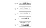
いくつかの実施例で、形状記憶合金はツイスト、回転、またはアレイ幾何形状を提供する。図6は、形状記憶合金を備える音響アレイの製造方法および音響アレイによる走査を示す。この方法は、図2のシステム、図1,7,8または10のアレイ、または種々異なるアレイおよび/またはシステムを使用する。付加的なステップ、別のステップを設けるか、またはステップを少なくすることも可能である。例えば幾何形状がステップ74で確定されず、アレイがステップ76で包囲されず、および/またはアレイがステップ78で使用されなくても良い。
In some embodiments, the shape memory alloy provides a twist, rotation, or array geometry. FIG. 6 shows a method of manufacturing an acoustic array comprising a shape memory alloy and scanning with the acoustic array. This method uses the system of FIG. 2, the array of FIGS. 1, 7, 8 or 10, or different arrays and / or systems. It is possible to provide additional steps, additional steps, or fewer steps. For example, the geometry may not be established at
ステップ70で、アレイの複数の超音波素子が形状記憶合金と結合される。結合はクランプまたは固定物への位置決めとすることができる。別の実施例で、エレメントは形状記憶合金とボンディングにより結合される。これは室温または高温(例えば50℃)でのエポキシ剤により行われる。例えば形状記憶合金は、アレイおよび超音波トランスデューサのために使用される他のトランスデューサ層と積層される(例えばバッキング、トレースを備えるフレキシブル回路、基板、および/またはマッチング層)。積層体は加圧され、硬化される。
At
形状記憶合金はアレイと直接接合するか、または1つまたは複数の別のコンポーネントを介して接合される。例えば形状記憶合金は、マッチング層のアレイ、トランスデューサ材料、およびバッキングブロックと積層される。フレキシブル回路のような導体が、トランスデューサ材料とバッキングブロックとの間から伸長する。過剰のフレキシブル回路材料は、バッキングブロックの後方に配置される。合金はバッキングブロックに対して直接積層されるか、または過剰のフレキシブル回路材料に対して、バッキングブロックの後方で積層される。 The shape memory alloy is bonded directly to the array or bonded via one or more other components. For example, a shape memory alloy is laminated with an array of matching layers, a transducer material, and a backing block. A conductor such as a flexible circuit extends from between the transducer material and the backing block. Excess flexible circuit material is placed behind the backing block. The alloy is laminated directly to the backing block or laminated behind the backing block for excess flexible circuit material.
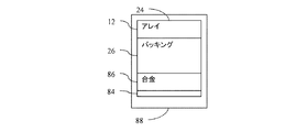
図7は、アレイ12とバッキングブロック26を介して結合された形状記憶合金86の実施例と、1つまたは複数の導体層、例えば相互に加圧されたフレキシブル回路のアコーディオン型積層体を示す。アレイ12は、任意のマッチング層および導体を備える、またはそれらなしでのトランスデューサ材料の積層体である。別の実施例で、アレイ12はトランスデューサ材料だけである。合金86はアレイ12の下方、バッキング材料26の下方、導体84の下方にある。導体84はアレイ12(例えばトランスデューサ材料とバッキングの間)からバッキング26の後方に伸長する。エンクロージャ88はエレメント24のアレイ12を包囲する。層はボンディングにより結合されている。エンクロージャ88はアレイ12の積層体と結合され、これに対して静止している。または、この積層体の周囲に離間している。
FIG. 7 shows an example of a
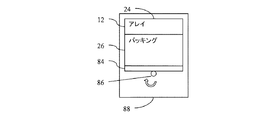
図8は図7に類似する、内部接続された積層体を示す。この積層体はバッキング26と導体84との間に形状記憶合金を備える。別の配置構成を使用することも可能である。
FIG. 8 shows an internally connected stack similar to FIG. This laminate includes a shape memory alloy between the backing 26 and the
図10は、図7および8のシートまたはプレートではなく、ロッドまたはチューブとしての形状記憶合金を示す。別の形状と任意の方向に沿った伸長を使用することができる。択一的に実施例で、ロッドはアレイに隣接する側で平坦であるが、底部側(すなわちアレイ12から離れる側)では円筒である。バッキング26に隣接する断面積は最大である。
FIG. 10 shows the shape memory alloy as a rod or tube rather than the sheet or plate of FIGS. Other shapes and extensions along any direction can be used. Alternatively, in an embodiment, the rod is flat on the side adjacent to the array, but is cylindrical on the bottom side (ie, the side away from the array 12). The cross-sectional area adjacent to the
図11は、形状記憶合金86を、図7と8に示した形状記憶合金86と関連する平坦なプレート構造として示す。これは加熱アクティベートの前である。
FIG. 11 shows the
図6のステップ72で、アレイの幾何形状が変更される。形状記憶合金は、アレイを含むトランスデューサプローブの製造中に幾何形状を変更する。合金はアレイを所望の幾何形状に変更する。任意の幾何形状を形状記憶合金により記憶することができる。例えば所望の幾何形状は偏平または平坦である。別の実施例として、所望の幾何形状は1つまたは複数の方向に沿った湾曲である(例えばアジマス方向に沿って湾曲しているが、上下方向には湾曲していない)。別の実施例で、所望の幾何形状はアレイの放射面に対してヘリカルな形状である。
In
変化は製造中に発生する。例えば変化は、アレイを形状記憶合金に結合した後に生じるが、完成したアレイを消費者に引き渡す前である。別の実施例として、変化は形状記憶合金をアレイに結合することにより生じる。アレイは形状記憶合金と結合するように変化される。実施例でアレイは形状記憶合金により、結合の後であってアレイをハウジング内に包囲する前または包囲する間に変化される。 Changes occur during manufacturing. For example, the change occurs after the array is bonded to the shape memory alloy, but before the completed array is delivered to the consumer. As another example, the change is caused by bonding a shape memory alloy to the array. The array is changed to bond with the shape memory alloy. In an embodiment, the array is changed by a shape memory alloy after bonding and before or during enclosure of the array within the housing.
実施例でアレイは、超弾性合金により所望の幾何形状に戻る。例えばアレイは製造中に走査によりツイストされ、曲げられ、ワープされ、変位される。形状記憶合金は所望の幾何形状を維持し、アレイを所望の幾何形状に変形して戻す。超弾性合金シート、ワイヤ、または他の形状が、図7から8および図10に示すように超音波アレイ12に付着される。超弾性合金86は、音響アレイ12表面の平坦形状または所望の幾何形状を維持する。カテーテル適用またはTEE適用では、アレイ12のバッキングブロックおよび/または他の材料を、寸法の制約のため薄くすることができる。相応にして、トランスデューサ積層体の寸法安定性は他の場合よりも小さくなる。多数のエレメントが所望であれば、アレイの側方広がり(例えばアジマス方向および/または上下方向)を拡張する。拡張された側方広がりにより、アレイ12をより容易に変形することができる。通常の製造中にアレイが不所望に変形する場合、この変形を音響アレイに取り付けた超弾性合金コンポーネントにより反転して戻すことができる。
In an embodiment, the array returns to the desired geometry with a superelastic alloy. For example, the array is twisted, bent, warped and displaced by scanning during manufacture. The shape memory alloy maintains the desired geometry and deforms the array back to the desired geometry. A superelastic alloy sheet, wire, or other shape is attached to the
この反転は形状記憶合金によっても択一的に行われる。所望の幾何形状に自動的に復帰するのではなく、形状記憶合金の温度また他の移行がアレイ12を所望の幾何形状に復帰させる。
This inversion is alternatively performed by a shape memory alloy. Rather than automatically returning to the desired geometry, the shape memory alloy temperature or other transition causes the
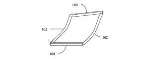
図9は、アレイの幾何形状を変化するための超弾性合金の別の使用を示す。固定物が超弾性合金ロッド102を含む。例えば2つの超弾性合金ロッド102が、同じまたは異なる材料の2つの端部ポケット100に付着する。超弾性合金ロッド102は、アレイ12を2つの端部ポケット100に挿入するために曲げられる。超弾性合金ロッド102は次に形状記憶によって種々異なって曲げられずに、または曲げられて、アレイ12を所望の幾何形状にする。
FIG. 9 illustrates another use of a superelastic alloy to change the geometry of the array. The fixture includes a
実施例でアレイ12は1つの形状から別の形状に、形状記憶合金86によって変化する。形状記憶合金86は、以前の状態から異なる記憶状態に移行する。
In an embodiment, the
熱または他の移行エネルギにより合金はアレイ形状を変化させる。例えば形状記憶合金、例えばニチノールが加熱される。熱が外部からトランスデューサ積層体および/またはトランスデューサプローブに適用される。例えば熱をプラスチック溶接機に適用すること、またはトランスデューサ積層体の周囲にハウジングを成形することも、形状記憶合金86を異なる幾何形状に移行させる。択一的に熱が内部からトランスデューサプローブに、トランスデューサハウジング内部にあり、形状記憶合金86に隣接する加熱素子により適用される。
The alloy changes the array shape due to heat or other transfer energy. For example, a shape memory alloy such as nitinol is heated. Heat is externally applied to the transducer stack and / or transducer probe. For example, applying heat to a plastic welder or forming a housing around the transducer stack also causes the
変形実施例で、形状記憶合金86は変化前に実質的に平坦な形状を有し、湾曲形状またはヘリカル形状に変化する。図11は、実質的に平坦な幾何形状を(アレイを曲げる前に)有する形状記憶合金86のシートを示す。移行後、図12はヘリカル形状を有する形状記憶合金86を示す(アレイをエンクロージャ内でプラスチック溶接した後)。アレイ12のエレメント24は、アレイの縦軸(すなわちアジマス軸)を中心にツイストされる。アレイ12は縦軸を中心に、らせん状または渦巻状にツイストされる。ツイストするとアレイの端部が回転する。および/またはアレイのエレメントまたはエレメント群が回転する。例えばアレイは、エレメントとカーフスの組合せを備える線形アレイとして形成される。カーフスは形状記憶合金86内に伸長するか、または伸長せず、またはアレイ12を形状記憶合金86に結合する前に成形される。
In an alternative embodiment, the
線形アレイは任意の量だけツイストされる。マッチング層および/または電極(例えばフレキシブル回路材料)は、ツイストによる層剥離を回避するために十分に撓むか、またはフレキシブルである。バッキングブロックはフレキシブルであり、充填剤を備える、または備えないシリコンおよび/またはエポキシである。バッキングは他の材料でも良く、および/またはフレキシビリティのために薄くすることができる(例えば0.05〜0.02インチ厚)。 The linear array is twisted by an arbitrary amount. The matching layer and / or electrode (eg, flexible circuit material) is sufficiently flexible or flexible to avoid delamination due to twist. The backing block is flexible and is silicon and / or epoxy with or without filler. The backing can be other materials and / or can be thin for flexibility (e.g., 0.05-0.02 inches thick).
形状記憶合金シート、ワイヤ、または他の形状が超音波アレイ12の裏側に付着され、アレイ12の幾何形状を変化させる。例えば図10が示すように形状記憶ロッド86がバッキング材料26の裏側にエポキシボンディングされている。引き続くカテーテルまたはTEEの製造のために、プラスチック溶接または他の熱適用が行われる。例えば接着剤(PSA)を備える、または備えないPETシートが、トランスデューサ積層体の周囲に焼ばめされるか、または溶接される。別の実施例として、カテーテルを形成する外側ハウジングPebaxが、トランスデューサ積層体を熱適用によって包囲する。プラスチック溶接の間、または他の熱適用ステップの間に、形状記憶合金86は元の形状または記憶した形状に戻る。これは例えば図12のヘリカル形状である。図10の例でロッドはツイストされている。熱適用のため、アレイ12を覆う熱可塑性物質88は、アレイ12が形状記憶合金86により規定される幾何形状をとることができるのに十分にソフトである。カテーテルのチップ(エンクロージャ)は、ツイストされない長方形のルーメンにより容易に作製することができる。アレイが挿入前にツイストされる場合、ツイストされた長方形チップルーメンが、アレイをチップに挿入するために使用される。
A shape memory alloy sheet, wire, or other shape is attached to the back side of the
別の実施例では、形状記憶合金86が、図9に示すようなフレームを提供する。固定と積層の組合わせをさらに安定させるために使用することができる。例えばニチノールのシートが、トランスデューサ積層体に積層される。シートの薄い壁は上方に撓み、トランスデューサ積層体の一部、または側面全体、または両側面を覆う。積層された部分とは異なる側壁形態は、シリンダまたは固体物にニチノールを提供する。薄いニチノールを積層体に使用することができ、付加的な安定性とトランスデューサ積層体サイズの最小化を得ることができる。
In another embodiment,
形状記憶合金に対して、移行は所望の温度で行われる。室温および/または体温以上の任意の温度を使用することができる。例えば形状記憶合金86は50℃以下の温度では変遷しない。積層体は50℃以下の温度でボンディングされる。変遷温度は他の製造温度以下であり、例えばプラスチック溶接温度以下である。低硬度のPebaxの場合、変遷は140℃以下の温度で発生する。他の温度を使用することができる。熱の別個に適用しても良い。例えば変遷は、プラスチック溶接中には生じないが、変遷のためにだけ適用される温度、またはトランスデューサプローブを形成するための他の目的で適用される温度で発生する。
For shape memory alloys, the transition occurs at the desired temperature. Any temperature above room temperature and / or body temperature can be used. For example, the
ステップ74でアレイ12の幾何形状は変化の後に固定される。変化は製造中に所望の幾何形状をセットする。この幾何形状はその後のすべての使用に対して同じである。例えばアレイ12は、図2に示すようにカテーテル11に使用される。製造中に幾何形状を固定した後、アレイ12は同じ幾何形状を、出荷、走査の用意、患者への挿入、および/または走査のために維持する。ストレスまたは緊張による幾何形状変化が発生しても、幾何形状の意図的な変化は生じない。択一的実施例で、アレイ12の幾何形状は後で変化される。例えば所望の形状が維持されるか、または製造中に提供される。構造体、ヒンジ、他の形状記憶合金、または他のデバイスが、使用中に幾何形状を変化するために設けられる(例えば平坦形状またはヘリカル形状からの変遷、またはその反対)。
At
ツイストされたアレイ12は定位置にフレーム、ハウジング、エポキシ剤、ガイドワイヤ、他の構造体、形状記憶合金86、またはそれらの組合せにより保持される。例えば形状記憶合金86はアレイ12の形状を変更する。マテリアルを積層体に付着し、アレイ12とボンディングするか、または他のマテリアルを、アレイ12を所望の幾何形状に維持するために使用することができる。アレイ12は定位置に接着剤により固定され、固体物が除去される。択一的に固体物をその場所に残すことができる。なぜなら固体物は完全に音響経路の外にあるからである。
The
形状記憶合金86は積層体内に残るか、または除去される。例えば形状記憶合金86はアレイ12の放射面側にある。ハウジング88のボンディング、トランスデューサ積層体のボンディング、またはトランスデューサ積層体へのマテリアル付加が、アレイ12を所望の位置に付加する。形状記憶合金86は剥離またはラッピングにより除去される。択一的に形状記憶合金86はマッチング層として作用するか、またはアレイ12の後方に配置される。
The
ステップ76でアレイ12はハウジング88により包囲される。アレイ12は保護材料、例えば絶縁材料のフィルムにより包囲される。実施例でアレイ12はトランスデューサプローブハウジング内に包囲される。例えばプラスチックハウジングが手持ち使用のために用いられる。アレイ12はカテーテル、TEEまたは他のハウジングに包囲される。エンクロージャは、クラムシェル、シュリンクラップ、または他のハウジングである。例えばプラスチック溶接は熱可塑性物質をアレイ12の少なくとも一部の周囲で包囲する。エポキシまたは他のボンディング剤をハウジング88とアレイ12との間に設けることができる。多層のハウジング材料を使用することができる。例えば1つの層は電気絶縁のためであり、別の層はプローブの外表面のためのものである。
At
ステップ78でアレイ12は幾何形状の変化なしで使用される。リニア、セクタ、Vector(R)、または他の超音波走査フォーマットを使用することができる。実施例でアレイ12はヘリカル形状を有する。アレイ12のエレメント24は、連続的に異なる画像形成面位置を提供するために使用される。アレイの1つの位置からの画像面は、アレイの別の位置ではなく別の方向に向く。アレイ12は位置固定されるが、走査中に位置を変化することもできる。
At
公知のあらゆる形状記憶合金または将来開発される形状記憶合金を使用することができる。例えばニチノールのような形状記憶合金が使用される。形状記憶合金は現在の形状と、記憶形状を有する。エネルギ、例えば熱の適用に基づき、形状記憶合金は現在の形状から記憶形状に戻る。変遷はアレイ12の放射面22を変化させる。例えば放射面22は実質的に平坦な幾何形状から固定された非平坦な幾何形状に変化する。
Any known shape memory alloy or a future developed shape memory alloy can be used. For example, a shape memory alloy such as Nitinol is used. Shape memory alloys have a current shape and a memory shape. Based on the application of energy, eg heat, the shape memory alloy returns from its current shape to its memory shape. The transition changes the
別の実施例で計86は超弾性合金である。超弾性合金は曲げることができ、ツイストすることができ、または他に変化することができるが、記憶形状に復帰する。例えば超弾性合金は、アレイ12の放射面22を、いずれかの歪みの後に所望の幾何形状に戻す。所望の幾何形状は、製造終了時に固定することができる。
In another embodiment, the total 86 is a superelastic alloy. The superelastic alloy can be bent, twisted, or otherwise changed, but returns to the memory shape. For example, a superelastic alloy returns the radiating
形状記憶合金86は任意のやり方でアレイ12と結合し、所望の影響を与えることができる。例えば形状記憶合金86はアレイ12と、図7〜8および図10に示すレンジ方向に沿って積層される。レンジ方向は、所定の位置での放射面22に対して実質的に直交する。形状記憶合金86のシートは実質的にアレイ12と同じアジマス広がりおよび上下広がりを有するが、それより小さくても大きくても良い。別の実施例で形状記憶合金86は、図9に示すようにフレームの一部である。
The
エレメント24は定位置に保持されるか、または形状記憶合金86により所望の幾何形状に戻るよう変化される。製造中に付加的な材料を付加し、エレメント24を形状記憶合金86により確定された幾何形状に保持することができる。付加的材料は形状記憶合金86、または後で使用するための永久的な双方の固定位置である。例えばエンクロージャ88(例えばPebax)を、アレイとフレキシブル接合バンドルとの間で締まりばめにプレモールドすることができる。エンクロージャ88は溶融され、アレイ12は合金によりツイストされ、すべての開放空間はエンクロージャ88の材料またはエポキシ剤によりエンクロージャ88内で充填される。養生の後、エレメント24は定位置に保持される。別の例として、フレームがエレメント24を定位置に保持する。別の実施例では、エポキシまたは他の接着剤がアレイ12の一部または全体を定位置に保持する。別のマテリアルおよび関連の構造を使用することもできる。カテーテルの実施例に対して、カテーテル11の本体は、回転されたエレメント24の位置での干渉を避けるため、またはその位置で保持するためにツイストまたは回転することができる。
バッキングブロック材料、電極、アースプレート、および/またはマッチング層は変形可能であり、エレメント24とツイストすることができる。例えば線形アレイとして使用されるアレイ12は、製造プロセスでは変化なしでツイストすることができる。択一的に、1つまたは複数の層を変化の後に形成し、変形を回避することができる。
The backing block material, electrode, ground plate, and / or matching layer can be deformed and twisted with the
実施例でフレックス回路は、バッキングブロックとPZTの間にある。フレックス回路はバッキングブロックの側面の周囲で曲げられ、バッキングブロックの後方で(アコーディオン状に)畳まれる。フレックス接続バンドル(アコーディオン)84内で、フレックス回路は導体14のバンドルと接続され、信号をビーム形成器16とアレイ12との間で伝送する。実施例で、フレックス接続バンドル14はバッキングブロックと合金86の間にある(図7参照)。別の実施例で、合金86はバッキングブロックとフレックス接続バンドル14の間に配置される(図8参照)。
In an embodiment, the flex circuit is between the backing block and the PZT. The flex circuit is bent around the sides of the backing block and folded (accordion-like) behind the backing block. Within the flex connection bundle (accordion) 84, the flex circuit is connected to the bundle of conductors 14 and transmits signals between the
種々異なる幾何形状を有するアレイを備えたトランスデューサが設けられている。例えばエレメントの種々の群が、異なってツイストまたは回転されている。種々異なるエレメントが相互に隣接している。例えば2つまたはそれ以上のアレイが実質的に平行である。実質的にとは、1つまたは複数のアレイが非線形軸を有するためである。および/またはアレイの軸に沿ったアレイの回転が種々異なっているためである。アレイは整列されており、平面の大きな範囲または大きな容積を走査することができる。1つのアレイは21°以上を走査し、別のアレイは他の21°以上を走査し、一つの容積を通じて42°が走査される。他の範囲を設けることもできる。 A transducer with an array having different geometries is provided. For example, various groups of elements are twisted or rotated differently. Different elements are adjacent to each other. For example, two or more arrays are substantially parallel. Substantially because one or more arrays have a non-linear axis. And / or because the rotation of the array along the axis of the array varies. The array is aligned and can scan a large area of a plane or a large volume. One array scans more than 21 °, another array scans more than 21 °, and 42 ° is scanned through one volume. Other ranges can also be provided.
図13は、異なる幾何形状を備える実質的に平行な4つのアレイのための形状記憶合金を示す。しかしながらそれよりも少ないアレイまたは多いアレイが用いられてもよい。図13の実施例で、アレイは一つおきに同じ方向の回転している。すなわち、2つのアレイは別の2つのアレイとは反対に回転している。すべてのアレイは隣接するアレイとは反対に回転している。各アレイの回転量は同じでも異なっていても良い。すべてのアレイが同じ方向に回転しても良い。同じアレイ構造、または異なるアレイ構造を各アレイに設けることができる。すなわちそれぞれのエレメント群での回転量、エレメント数、アレイの長さ、エレメント形式、またはエレメントサイズは同じでも異なっていても良い。 FIG. 13 shows a shape memory alloy for four substantially parallel arrays with different geometries. However, fewer or more arrays may be used. In the embodiment of FIG. 13, every other array rotates in the same direction. That is, the two arrays are rotating in opposition to the other two arrays. All arrays are rotated opposite to the adjacent array. The rotation amount of each array may be the same or different. All arrays may rotate in the same direction. The same array structure or different array structures can be provided for each array. That is, the amount of rotation, the number of elements, the length of the array, the element type, or the element size in each element group may be the same or different.
アレイは相互に隣接する。図13に示すように、アレイおよび/または形状記憶合金は結合することができる。例えば形状記憶合金はアレイの端部に交互に結合されており、アレイの相対位置に剛性を提供する。結合された端部は平坦である(例えば同じ方向に向けられた放射面を有する)。または結合されたアレイにわたって平坦ではない。結合された端部にある放射面は走査領域に重なるように向けられている(例えば放射面は相互に向き合うように角付けられている)。または別個の走査領域に向けられている(例えば放射面は相互に背く)。オーバラップにより、データベースの相関記録、またはアレイの適切な相対位置の確認が行われる。択一的にアレイは別のアレイから離間されている。 The arrays are adjacent to each other. As shown in FIG. 13, the array and / or shape memory alloy can be bonded. For example, shape memory alloys are alternately bonded to the ends of the array and provide rigidity to the relative position of the array. The joined ends are flat (eg, with radiating surfaces oriented in the same direction). Or not flat across the combined array. Radiation surfaces at the combined ends are oriented to overlap the scan area (eg, the radiation surfaces are angled to face each other). Or they are directed to separate scanning areas (e.g., the emitting surfaces are opposite each other). Overlap results in a correlation record in the database or confirmation of the appropriate relative position of the array. Alternatively, the array is spaced from another array.
アレイは、オーバラップあり、またはなしで種々の領域を走査するよう角付けられている。相対位置とアレイ幾何形状は、図4および5で一つのアレイについて示すように走査される種々の領域を規定する。別のアレイを同じ形式の走査に使用することができるが、相対位置は異なっている。実施例で、4つのアレイが約84°をカバーし、各アレイは21°をカバーする。各アレイのカバレッジは、アレイに沿ったアパーチャ選択に基づく。 The array is angled to scan various regions with or without overlap. Relative position and array geometry define the various regions that are scanned as shown for one array in FIGS. Different arrays can be used for the same type of scan, but the relative positions are different. In the example, four arrays cover approximately 84 ° and each array covers 21 °. The coverage of each array is based on the aperture selection along the array.
択一的実施例で、アレイは平行ではなく、一般的に直交軸を有するように配置されている。2つまたはそれ以上のツイストされたアレイの配置構成を設けることもできる。 In an alternative embodiment, the arrays are not parallel but are generally arranged to have orthogonal axes. Two or more twisted array arrangements may be provided.
アレイの製造中、形状記憶合金はフラットである。形状記憶合金は、種々のアレイを少なくとも部分的に分離するカットを含むことができる。択一的に、合金はアレイ製造中にカットされる。アレイ間を方形切断するエレメントは、バッキングブロックのすべてまたは大部分を通る。アレイがいったん方形切断されると、形状記憶によりアレイは所望の幾何形状にツイストされる。1つまたは複数のアレイがツイストされなくても良い。図13の実施例で、第1のアレイと第3のアレイは右にツイストされており、第2のアレイと第4のアレイは左にツイストされている。 During the manufacture of the array, the shape memory alloy is flat. The shape memory alloy can include cuts that at least partially separate the various arrays. Alternatively, the alloy is cut during array manufacture. Elements that square cut between arrays pass through all or most of the backing block. Once the array is square cut, shape memory twists the array into the desired geometry. One or more arrays may not be twisted. In the example of FIG. 13, the first and third arrays are twisted to the right, and the second and fourth arrays are twisted to the left.
相互に隣接する2つのアレイについては、フレックス回路または導体は、各アレイの露出側に別のアレイから案内されている。3つ以上の隣接するアレイについては、1つまたは複数のアレイが別のアレイに接近するまたは離れる両サイドを有している。共有フレックス回路を使用することができる。2つのアレイからのトレースに対する空間が、フレックス回路の一方の側で不十分であれば、多層フレックス回路を使用することができる。例えば1つのアレイからのトレースは、フレックス材料の一方の側で案内される。フレックス材料は多重アレイを接続する。1つのアレイからのトレースは、フレックス材料の他方の側へ案内される。別の信号案内を使用することもできる。 For two arrays adjacent to each other, the flex circuit or conductor is guided from another array on the exposed side of each array. For more than two adjacent arrays, one or more arrays have both sides approaching or leaving another array. A shared flex circuit can be used. If the space for the traces from the two arrays is insufficient on one side of the flex circuit, a multilayer flex circuit can be used. For example, traces from one array are guided on one side of the flex material. Flex material connects multiple arrays. Traces from one array are guided to the other side of the flex material. Other signal guidance can also be used.
これまで本発明について様々な実施形態に基づき説明してきたが、本発明の範囲から逸脱することなく種々の変更ないし修正を行えることは自明である。したがって上記における詳細な説明は制限を意図しているもののではなく説明を意図しているものであり、本発明の精神および範囲を定めるのは、すべての同等のものを含む添付の特許請求の範囲であると解される。 Although the present invention has been described above based on various embodiments, it is obvious that various changes and modifications can be made without departing from the scope of the present invention. Accordingly, the above detailed description is intended to be illustrative rather than limiting and the spirit and scope of the invention is defined by the appended claims, including all equivalents thereof It is understood that.
Claims (17)
第1のアレイ(12)の複数の第1のエレメント(24)と、第2のアレイ(12)の複数の第2のエレメント(24)と、前記複数の第1のエレメント(24)および前記複数の第2のエレメント(24)にそれぞれ接続されている各電気導体(14)とを有しており、
・該第1のアレイ(12)の複数の第1のエレメント(24)は、該第1のアレイ(12)の第1の放射面(22)を規定しており、
複数の前記第1のエレメント(24)はアジマス軸に沿って離間されており、
前記第1のアレイ(12)の第1のエレメント(24)のいくつかは、前記アジマス軸を中心に、別のいくつかの第1のエレメント(24)に対してツイストされた関係で回転されており、
前記第1の放射面(22)は、回転に基づき異なる方向に角付けられており、
・該第2のアレイ(12)の複数の第2のエレメント(24)は、該第2のアレイ(12)の第2の放射面(22)を規定しており、
複数の前記第2のエレメント(24)はアジマス軸に沿って離間されており、
前記第2のアレイ(12)の第2のエレメント(24)のいくつかは、前記アジマス軸を中心に、別のいくつかの第2のエレメント(24)に対してツイストされた関係で回転されており、
前記第2の放射面(22)は、回転に基づき異なる方向に角付けられており、
前記第1のアレイ(12)と前記第2のアレイ(12)とは、隣接する第1の端部と第2の端部とにそれぞれ接続されており、かつ、反対方向に回転されている、
ことを特徴とするシステム。 A system (10) for an acoustic transducer, the system (10) comprising:
A plurality of first elements (24) of a first array (12); a plurality of second elements (24) of a second array (12); the plurality of first elements (24); Each electrical conductor (14) connected to each of a plurality of second elements (24),
A plurality of first elements (24) of the first array (12) define a first radiation surface (22) of the first array (12);
A plurality of said first elements (24) are spaced along the azimuth axis;
Some of the first elements (24) of the first array (12) are rotated in a twisted relationship with respect to several other first elements (24) about the azimuth axis. And
The first radiation surface (22) is angled in different directions based on rotation;
A plurality of second elements (24) of the second array (12) define a second radiation surface (22) of the second array (12);
A plurality of said second elements (24) are spaced along the azimuth axis;
Some of the second elements (24) of the second array (12) are rotated in a twisted relationship with respect to some other second elements (24) about the azimuth axis. And
The second radiation surface (22) is angled in different directions based on rotation,
The first array (12) and the second array (12) are respectively connected to the adjacent first end and second end and rotated in opposite directions. ,
A system characterized by that.
前記第1のエレメント(24)は、アジマス軸を中心に第1のヘリカルパターンで回転されており、
前記放射面(22)は回転に基づいてツイストされており、
前記第2のエレメント(24)は、アジマス軸を中心に第2のヘリカルパターンで回転されており、
前記放射面(22)は回転に基づいてツイストされている、システム。 The system (10) of claim 1, comprising:
The first element (24) is rotated in a first helical pattern about the azimuth axis,
The radiation surface (22) is twisted based on rotation;
The second element (24) is rotated in a second helical pattern about the azimuth axis,
The radiation surface (22) is twisted based on rotation, the system.
前記第1のアレイ(12)の対向端部にある前記エレメント(24)は、アジマス軸を中心に相互に少なくとも10°だけ回転されており、
前記第1の放射面(22)もアジマス軸を中心に少なくとも10°だけ回転されている、システム。 The system (10) of claim 1, comprising:
The elements (24) at opposite ends of the first array (12) have been rotated at least 10 ° relative to each other about an azimuth axis;
The system, wherein the first emitting surface (22) is also rotated at least 10 ° about the azimuth axis.
前記複数の第1のエレメント(24)の少なくとも55個がアジマス軸に沿っており、
各第1のエレメント(24)は少なくとも1つの隣接するエレメント(24)に対して回転されている、システム。 The system (10) of claim 1, comprising:
At least 55 of the plurality of first elements (24) are along the azimuth axis;
The system, wherein each first element (24) is rotated relative to at least one adjacent element (24).
前記第1および前記第2のエレメント(24)を回転された位置に保持する形状記憶合金(86)を有する、システム。 The system (10) according to claim 1, further comprising:
A system comprising a shape memory alloy (86) that holds the first and second elements (24) in a rotated position.
経食道プローブ(11)を有し、
前記第1および第2のアレイ(12)は、前記プローブ(11)内に、前記第1および第2のエレメント(24)が回転された位置で位置決めされている、システム。 The system (10) according to claim 1, further comprising:
A transesophageal probe (11),
The system wherein the first and second arrays (12) are positioned in the probe (11) at a position where the first and second elements (24) have been rotated.
前記複数の導体(14)と接続されたビーム形成器(16)と、プロセッサ(18)とを有し、
該ビーム形成器(16)は、隣接する一群の第1および第2のエレメント(24)により形成された複数のアパーチャから走査し、
該プロセッサ(18)は、3次元データセットを、前記ビーム形成器(16)による走査に応じて生成する、システム。 The system (10) according to claim 1, further comprising:
A beamformer (16) connected to the plurality of conductors (14) and a processor (18);
The beamformer (16) scans from a plurality of apertures formed by a group of adjacent first and second elements (24);
The processor (18) generates a three-dimensional data set in response to scanning by the beamformer (16).
前記第1および第2のアレイ(12)に接続された第3および第4のアレイ(12)を有し、
前記第3および第4のアレイ(12)はツイストされた関係で回転しており、
前記第1,第2,第3,および第4のアレイ(12)は、当該第1,第2,第3および第4のアレイ(12)の隣接するアレイとは反対方向に回転している、システム。 The system (10) according to claim 1, further comprising:
Having third and fourth arrays (12) connected to said first and second arrays (12);
The third and fourth arrays (12) are rotating in a twisted relationship;
The first, second, third and fourth arrays (12) rotate in the opposite direction to the adjacent array of the first, second, third and fourth arrays (12). ,system.
少なくとも1つの第1のアレイのアジマス軸と少なくとも1つの第2のアレイのアジマス軸とが、前記複数のエレメント(24)が、少なくとも2つのらせんを構成するように配置されていることによって、
前記少なくとも2つのらせんの各アジマス軸に沿ってグループごとに離間された、少なくとも1つのエレメント(24)の異なるグループが、上下方向に積層され、かつ、アジマス方向に同等の広がりを有する、異なる平面領域(58,60,62)を走査することができ、
当該異なる平面領域が少なくとも2つのらせんの異なる1つを使用して走査される、システム。 The system according to any one of claims 1 to 8, comprising:
By disposing at least one first array azimuth axis and at least one second array azimuth axis such that the plurality of elements (24) constitute at least two helices,
Different planes, wherein different groups of at least one element (24), spaced apart in groups along each azimuth axis of the at least two helices, are stacked vertically and have an equal extent in the azimuth direction Region (58, 60, 62) can be scanned;
The system, wherein the different planar areas are scanned using different ones of at least two helices.
各らせんのエレメント(24)は前記トランスデューサの放射面(22)を規定し、
各放射面(22)は、前記らせんに基づき異なる方向に角付けられている、システム。 The system of claim 9, comprising:
Each helical element (24) defines a radiation surface (22) of the transducer;
Each radiation surface (22) is angled in a different direction based on the helix.
前記トランスデューサの各らせんの対向端部にある前記エレメント(24)は、前記アジマス軸を中心に相互に少なくとも10°だけ回転されている、システム。 The system of claim 9, comprising:
The system, wherein the elements (24) at opposite ends of each helix of the transducer are rotated at least 10 ° relative to each other about the azimuth axis.
各エレメント(24)はアジマス方向に実質的に波長と同じに、または波長より小さく離間されており、
さらに前記エレメント(24)を前記らせんに位置決めする形状記憶合金(86)を有する、システム。 The system of claim 9, comprising:
Each element (24) is spaced substantially the same as or less than the wavelength in the azimuth direction;
The system further comprising a shape memory alloy (86) for positioning the element (24) in the helix.
前記らせんは実質的に平行なアレイ(12)であり、
前記アレイは両方のらせんを支持する一体構造の形状記憶合金(86)を備える、システム。 13. The system according to claim 12, wherein
The helix is a substantially parallel array (12);
The array comprises a unitary shape memory alloy (86) that supports both helices.
前記トランスデューサは経食道トランスデューサを含む、システム。 The system of claim 9, comprising:
The system, wherein the transducer comprises a transesophageal transducer.
前記少なくとも2つのらせんは少なくとも3つのらせんを含む、システム。 The system of claim 9, comprising:
The system, wherein the at least two helices include at least three helices.
・第1のアパーチャ(52)をエレメント(24)の第1のアレイ(12)上に形成するステップ(42)、
前記エレメント(24)の第1のアレイ(12)は第1の縦軸を中心に第1のツイスト角度でツイストされており;
・第1の平面(58)の走査データを得るために、前記第1のアパーチャ(52)を介して走査ビームを送受信するステップ;
・別の第2のアパーチャ(54)を、前記エレメント(24)の第1のアレイ(12)上に形成するステップ(46)、
前記第2のアパーチャ(54)は、前記第1のアパーチャ(52)がアジマス方向に前記エレメント(24)の第1のアレイ(12)に沿って移動したものに相当し、
前記第1のアレイ(12)のエレメント(24)は、前記第1の縦軸を中心にツイストされたエレメント(24)により規定されるラインと同じラインに沿っており;
・前記第1の平面(58)とは異なる第2の平面(60)の走査データを得るために、前記第2のアパーチャ(54)を介して走査ビームを送受信するステップ;
前記第2の平面(60)の位置は、第2のツイスト角度に相当し、当該第2のツイスト角度は、前記第1のツイスト角度とは異なり、
・前記形成するステップと前記走査ビームを送受信するステップを、第2の縦軸を中心にツイストされたエレメント(24)の第2のアレイ(12)により反復するステップ、なお、前記第1のアレイ(12)と第2のアレイ(12)とは、隣接する第1の端部と第2の端部とにそれぞれ接続されており、かつ、反対方向に回転されている、
・3次元表示を、前記走査データと前記第1および第2の平面の相対位置に応じて生成するステップ(50)、
を有する、方法。 A method of operating a system for acoustic transducers, the method comprises the following steps:
Forming a first aperture (52) on the first array (12) of elements (24);
A first array (12) of said elements (24) is twisted at a first twist angle about a first longitudinal axis ;
Transmitting and receiving a scanning beam via the first aperture (52) to obtain scanning data of the first plane (58);
The-separate second aperture (54) is formed on the first array of elements (24) (12) Step (46),
The second aperture (54) corresponds to the first aperture (52) moved along the first array (12) of the elements (24) in the azimuth direction;
The elements (24) of the first array (12) are along the same line as the lines defined by the elements (24) twisted about the first longitudinal axis ;
Transmitting and receiving a scanning beam through the second aperture (54) to obtain scanning data of a second plane (60) different from the first plane (58);
The position of the second plane (60) corresponds to a second twist angle, and the second twist angle is different from the first twist angle,
Repeating the forming step and the step of transmitting and receiving the scanning beam with a second array (12) of elements (24) twisted about a second longitudinal axis, wherein the first array (12) and the second array (12) are respectively connected to adjacent first and second ends and rotated in opposite directions;
- a three-dimensional representation is generated in accordance with the relative position of the scanning data and said first and second planar step (50),
The having, way.
前記音響トランスデューサが、
経食道プローブ(11)用のトランスデューサである、方法。
A way of claim 16,
The acoustic transducer comprises:
A method , which is a transducer for a transesophageal probe (11).
Applications Claiming Priority (2)
| Application Number | Priority Date | Filing Date | Title |
|---|---|---|---|
| US12/237,249 | 2008-09-24 | ||
| US12/237,249 US8206305B2 (en) | 2006-11-28 | 2008-09-24 | Multi-twisted acoustic array for medical ultrasound |
Publications (3)
| Publication Number | Publication Date |
|---|---|
| JP2010088877A JP2010088877A (en) | 2010-04-22 |
| JP2010088877A5 JP2010088877A5 (en) | 2014-04-10 |
| JP5709366B2 true JP5709366B2 (en) | 2015-04-30 |
Family
ID=42046830
Family Applications (1)
| Application Number | Title | Priority Date | Filing Date |
|---|---|---|---|
| JP2009217361A Active JP5709366B2 (en) | 2008-09-24 | 2009-09-18 | System for acoustic transducer for medical ultrasound and method of operating the system |
Country Status (5)
| Country | Link |
|---|---|
| US (1) | US8206305B2 (en) |
| JP (1) | JP5709366B2 (en) |
| KR (1) | KR101621716B1 (en) |
| CN (1) | CN101683275B (en) |
| DE (1) | DE102009042204B4 (en) |
Cited By (3)
| Publication number | Priority date | Publication date | Assignee | Title |
|---|---|---|---|---|
| US11717258B2 (en) | 2020-05-12 | 2023-08-08 | GE Precision Healthcare LLC | Methods and systems for a shape-changing invasive deployable device |
| US11998393B2 (en) | 2020-10-20 | 2024-06-04 | GE Precision Healthcare LLC | System and method of signal processing for ultrasound arrays with mechanically adjustable transducer shapes |
| US12201024B2 (en) | 2020-05-12 | 2025-01-14 | GE Precision Healthcare LLC | Methods for forming an invasive deployable transducer using shape memory polymer |
Families Citing this family (38)
| Publication number | Priority date | Publication date | Assignee | Title |
|---|---|---|---|---|
| US8473239B2 (en) | 2009-04-14 | 2013-06-25 | Maui Imaging, Inc. | Multiple aperture ultrasound array alignment fixture |
| EP2088932B1 (en) * | 2006-10-25 | 2020-04-08 | Maui Imaging, Inc. | Method and apparatus to produce ultrasonic images using multiple apertures |
| US8449467B2 (en) * | 2006-11-28 | 2013-05-28 | Siemens Medical Solutions Usa, Inc. | Helical acoustic array for medical ultrasound |
| US9282945B2 (en) | 2009-04-14 | 2016-03-15 | Maui Imaging, Inc. | Calibration of ultrasound probes |
| US9788813B2 (en) | 2010-10-13 | 2017-10-17 | Maui Imaging, Inc. | Multiple aperture probe internal apparatus and cable assemblies |
| WO2010017445A2 (en) * | 2008-08-08 | 2010-02-11 | Maui Imaging, Inc. | Imaging with multiple aperture medical ultrasound and synchronization of add-on systems |
| KR20110137829A (en) * | 2009-04-14 | 2011-12-23 | 마우이 이미징, 인코포레이티드 | Universal Multi-Aperture Medical Ultrasound Probe |
| EP2536339B1 (en) | 2010-02-18 | 2024-05-15 | Maui Imaging, Inc. | Point source transmission and speed-of-sound correction using multi-aperture ultrasound imaging |
| US9668714B2 (en) | 2010-04-14 | 2017-06-06 | Maui Imaging, Inc. | Systems and methods for improving ultrasound image quality by applying weighting factors |
| JP6092109B2 (en) | 2010-10-13 | 2017-03-08 | マウイ イマギング,インコーポレーテッド | Concave ultrasonic transducer and 3D array |
| US8922554B2 (en) | 2011-03-18 | 2014-12-30 | Siemens Medical Solutions Usa, Inc. | Three-dimensional reconstruction for irregular ultrasound sampling grids |
| US9759691B2 (en) * | 2011-05-10 | 2017-09-12 | Cumberland & Western Resources, Llc | Gating methods for use in weld inspection systems |
| WO2013082455A1 (en) | 2011-12-01 | 2013-06-06 | Maui Imaging, Inc. | Motion detection using ping-based and multiple aperture doppler ultrasound |
| JP2015503404A (en) | 2011-12-29 | 2015-02-02 | マウイ イマギング,インコーポレーテッド | Arbitrary path M-mode ultrasound imaging |
| JP6438769B2 (en) | 2012-02-21 | 2018-12-19 | マウイ イマギング,インコーポレーテッド | Determination of material hardness using multiple aperture ultrasound. |
| WO2014026185A1 (en) | 2012-08-10 | 2014-02-13 | Maui Imaging, Inc. | Calibration of multiple aperture ultrasound probes |
| CN103676827A (en) | 2012-09-06 | 2014-03-26 | Ip音乐集团有限公司 | System and method for remotely controlling audio equipment |
| EP3893022B1 (en) | 2012-09-06 | 2025-02-12 | Maui Imaging, Inc. | Ultrasound imaging system memory architecture |
| DE102012111889B9 (en) * | 2012-12-06 | 2014-09-04 | Epcos Ag | Electroacoustic transducer |
| WO2014160291A1 (en) | 2013-03-13 | 2014-10-02 | Maui Imaging, Inc. | Alignment of ultrasound transducer arrays and multiple aperture probe assembly |
| JP6389521B2 (en) | 2013-07-24 | 2018-09-12 | コーニンクレッカ フィリップス エヌ ヴェKoninklijke Philips N.V. | Non-imaging two-dimensional array probe and system for automated screening of carotid artery stenosis |
| US9883848B2 (en) | 2013-09-13 | 2018-02-06 | Maui Imaging, Inc. | Ultrasound imaging using apparent point-source transmit transducer |
| US9833219B2 (en) | 2014-03-26 | 2017-12-05 | Siemens Medical Solutions Usa, Inc. | Angle oriented array for medical ultrasound |
| KR102617888B1 (en) | 2014-08-18 | 2023-12-22 | 마우이 이미징, 인코포레이티드 | Network-based ultrasound imaging system |
| KR102681141B1 (en) | 2015-03-30 | 2024-07-02 | 마우이 이미징, 인코포레이티드 | Ultrasonic imaging systems and methods for detecting object motion |
| EP3294138B1 (en) * | 2015-05-11 | 2020-12-02 | Koninklijke Philips N.V. | Deformable ultrasound array and system |
| US9824442B2 (en) | 2015-08-20 | 2017-11-21 | Siemens Medical Solutions Usa, Inc. | View direction adaptive volume ultrasound imaging |
| EP4697068A3 (en) | 2016-01-27 | 2026-04-22 | Maui Imaging, Inc. | Ultrasound imaging with sparse array probes |
| WO2018016128A1 (en) * | 2016-07-19 | 2018-01-25 | オリンパス株式会社 | Ultrasonic probe |
| JP2018029645A (en) * | 2016-08-22 | 2018-03-01 | セイコーエプソン株式会社 | Ultrasonic device and ultrasonic measurement apparatus |
| KR102403733B1 (en) * | 2017-12-01 | 2022-05-30 | 삼성전자주식회사 | Memory devices |
| US10656007B2 (en) * | 2018-04-11 | 2020-05-19 | Exo Imaging Inc. | Asymmetrical ultrasound transducer array |
| CN109524423A (en) * | 2018-09-29 | 2019-03-26 | 中国科学院半导体研究所 | It can pretend deformable intelligent visible light near infrared detector and preparation method thereof |
| WO2021118974A1 (en) * | 2019-12-09 | 2021-06-17 | The Regents Of The University Of California | System and method for diagnosing pulsatile tinnitus and other blood vessel disorders |
| JP7724853B2 (en) | 2020-10-21 | 2025-08-18 | マウイ イマギング,インコーポレーテッド | Systems and methods for tissue characterization using multiple aperture ultrasound |
| CN116635162A (en) | 2020-11-02 | 2023-08-22 | 毛伊图像公司 | Systems and methods for improving ultrasound image quality |
| US12582378B2 (en) | 2021-04-05 | 2026-03-24 | GE Precision Healthcare LLC | Methods and systems for an invasive deployable device using a shape memory material to reconfigure transducer elements in response to stimuli |
| CN121622127A (en) * | 2025-12-30 | 2026-03-10 | 上海爱声生物医疗科技有限公司 | A method for extending the imaging range of an ICE catheter with controllable helical deformation of a microarray. |
Family Cites Families (34)
| Publication number | Priority date | Publication date | Assignee | Title |
|---|---|---|---|---|
| US4202050A (en) * | 1969-11-28 | 1980-05-06 | Martin Klein | Multi-angular sector sound transmitting and receiving system |
| US4515017A (en) * | 1983-11-21 | 1985-05-07 | Advanced Technology Laboratories, Inc. | Oscillating ultrasound scanhead |
| US4567895A (en) * | 1984-04-02 | 1986-02-04 | Advanced Technology Laboratories, Inc. | Fully wetted mechanical ultrasound scanhead |
| US5304115A (en) * | 1991-01-11 | 1994-04-19 | Baxter International Inc. | Ultrasonic angioplasty device incorporating improved transmission member and ablation probe |
| US5199437A (en) * | 1991-09-09 | 1993-04-06 | Sensor Electronics, Inc. | Ultrasonic imager |
| US7497828B1 (en) * | 1992-01-10 | 2009-03-03 | Wilk Ultrasound Of Canada, Inc. | Ultrasonic medical device and associated method |
| US5291893A (en) * | 1992-10-09 | 1994-03-08 | Acoustic Imaging Technologies Corporation | Endo-luminal ultrasonic instrument and method for its use |
| US5505205A (en) * | 1993-01-08 | 1996-04-09 | Hewlett-Packard Company | Interface element for medical ultrasound transducer |
| US5388584A (en) * | 1994-04-15 | 1995-02-14 | Hewlett-Packard Company | Method and apparatus for prevention of fluid intrusion in a probe shaft |
| US5546946A (en) * | 1994-06-24 | 1996-08-20 | Advanced Technology Laboratories, Inc. | Ultrasonic diagnostic transducer array with elevation focus |
| EP0883860B1 (en) * | 1996-02-29 | 2006-08-23 | Acuson Corporation | Multiple ultrasound image registration system, method and transducer |
| US5680863A (en) * | 1996-05-30 | 1997-10-28 | Acuson Corporation | Flexible ultrasonic transducers and related systems |
| US5735282A (en) * | 1996-05-30 | 1998-04-07 | Acuson Corporation | Flexible ultrasonic transducers and related systems |
| US5876345A (en) * | 1997-02-27 | 1999-03-02 | Acuson Corporation | Ultrasonic catheter, system and method for two dimensional imaging or three-dimensional reconstruction |
| US5916168A (en) * | 1997-05-29 | 1999-06-29 | Advanced Technology Laboratories, Inc. | Three dimensional M-mode ultrasonic diagnostic imaging system |
| EP0926491A1 (en) * | 1997-12-24 | 1999-06-30 | Sulzer Innotec Ag | Ultrasonic measuring apparatus and system and the use thereof |
| US6447478B1 (en) * | 1998-05-15 | 2002-09-10 | Ronald S. Maynard | Thin-film shape memory alloy actuators and processing methods |
| US5997479A (en) | 1998-05-28 | 1999-12-07 | Hewlett-Packard Company | Phased array acoustic systems with intra-group processors |
| US6123602A (en) * | 1998-07-30 | 2000-09-26 | Lucent Technologies Inc. | Portable slurry distribution system |
| US6059731A (en) * | 1998-08-19 | 2000-05-09 | Mayo Foundation For Medical Education And Research | Simultaneous side-and-end viewing underfluid catheter |
| US6159153A (en) * | 1998-12-31 | 2000-12-12 | Duke University | Methods and systems for ultrasound scanning using spatially and spectrally separated transmit ultrasound beams |
| US7264587B2 (en) * | 1999-08-10 | 2007-09-04 | Origin Medsystems, Inc. | Endoscopic subxiphoid surgical procedures |
| US6592520B1 (en) * | 2001-07-31 | 2003-07-15 | Koninklijke Philips Electronics N.V. | Intravascular ultrasound imaging apparatus and method |
| US6795374B2 (en) * | 2001-09-07 | 2004-09-21 | Siemens Medical Solutions Usa, Inc. | Bias control of electrostatic transducers |
| US6969354B1 (en) * | 2001-09-25 | 2005-11-29 | Acuson Corporation | Adaptable intraoperative or endocavity ultrasound probe |
| CN1646065B (en) * | 2002-04-17 | 2012-02-08 | 株式会社日立医药 | Intrabody Ultrasound Probe |
| US6709396B2 (en) * | 2002-07-17 | 2004-03-23 | Vermon | Ultrasound array transducer for catheter use |
| US6676602B1 (en) * | 2002-07-25 | 2004-01-13 | Siemens Medical Solutions Usa, Inc. | Two dimensional array switching for beamforming in a volume |
| EP1444953A1 (en) * | 2003-02-10 | 2004-08-11 | Sulzer Markets and Technology AG | Ultrasound probe for a stereoscopic imaging system |
| US7666143B2 (en) * | 2004-12-14 | 2010-02-23 | Siemens Medical Solutions Usa, Inc. | Array rotation for ultrasound catheters |
| EP1902331B1 (en) | 2005-05-04 | 2012-07-11 | Volcano Corporation | Miniature actuator mechanism for intravascular imaging |
| US7622853B2 (en) * | 2005-08-12 | 2009-11-24 | Scimed Life Systems, Inc. | Micromachined imaging transducer |
| US7500954B2 (en) * | 2005-09-22 | 2009-03-10 | Siemens Medical Solutions Usa, Inc. | Expandable ultrasound transducer array |
| US8449467B2 (en) * | 2006-11-28 | 2013-05-28 | Siemens Medical Solutions Usa, Inc. | Helical acoustic array for medical ultrasound |
-
2008
- 2008-09-24 US US12/237,249 patent/US8206305B2/en active Active
-
2009
- 2009-09-18 DE DE102009042204.8A patent/DE102009042204B4/en active Active
- 2009-09-18 JP JP2009217361A patent/JP5709366B2/en active Active
- 2009-09-24 KR KR1020090090619A patent/KR101621716B1/en active Active
- 2009-09-24 CN CN200910176299.5A patent/CN101683275B/en active Active
Cited By (3)
| Publication number | Priority date | Publication date | Assignee | Title |
|---|---|---|---|---|
| US11717258B2 (en) | 2020-05-12 | 2023-08-08 | GE Precision Healthcare LLC | Methods and systems for a shape-changing invasive deployable device |
| US12201024B2 (en) | 2020-05-12 | 2025-01-14 | GE Precision Healthcare LLC | Methods for forming an invasive deployable transducer using shape memory polymer |
| US11998393B2 (en) | 2020-10-20 | 2024-06-04 | GE Precision Healthcare LLC | System and method of signal processing for ultrasound arrays with mechanically adjustable transducer shapes |
Also Published As
| Publication number | Publication date |
|---|---|
| KR101621716B1 (en) | 2016-05-17 |
| CN101683275A (en) | 2010-03-31 |
| DE102009042204B4 (en) | 2021-05-20 |
| KR20100034724A (en) | 2010-04-01 |
| DE102009042204A1 (en) | 2010-05-06 |
| US20090010459A1 (en) | 2009-01-08 |
| CN101683275B (en) | 2014-01-22 |
| JP2010088877A (en) | 2010-04-22 |
| US8206305B2 (en) | 2012-06-26 |
Similar Documents
| Publication | Publication Date | Title |
|---|---|---|
| JP2010088877A (en) | Multi-twisted acoustic array for medical ultrasound | |
| US10405830B2 (en) | Manufacture of an acoustic array with a shape alloy | |
| JP5073276B2 (en) | A rotatable transducer array for volumetric ultrasound | |
| JP6363097B2 (en) | Focused rotation IVUS transducer using single crystal composite material | |
| JP2010088877A5 (en) | System for an acoustic transducer for medical ultrasound and a scanning method using the acoustic transducer | |
| JP5391241B2 (en) | Ultrasonic probe and ultrasonic imaging apparatus | |
| US20050131302A1 (en) | Ultrasonic probe having a selector switch | |
| US20180064415A1 (en) | Acoustic ablation assisted intra-cardiac echocardiography catheter | |
| US20110137176A1 (en) | Ultrasound transducer finger probe | |
| US20080045838A1 (en) | Ultrasonic transducer array, ultrasonic probe, ultrasonic endoscope and ultrasonic diagnostic apparatus | |
| JP2007152127A (en) | Ultrasonic imaging transducer array for synthetic aperture | |
| JP2001037760A (en) | Ultrasonic wave probe | |
| JP2007167650A (en) | Imaging catheter and method for volumetric ultrasound | |
| US9833219B2 (en) | Angle oriented array for medical ultrasound | |
| CN102451021A (en) | Tissue insertion type ultrasonic probe | |
| JP4740770B2 (en) | Ultrasonic probe and ultrasonic imaging apparatus | |
| CN117917957A (en) | Intracavity ultrasound imaging assembly with electrical connections for a multi-row transducer array | |
| JP3553923B2 (en) | Forward looking ultrasonic probe and method of manufacturing the same | |
| CN112450984A (en) | Ultrasonic endoscope system and ultrasonic transducer thereof | |
| JP2001258088A (en) | Ultrasound probe | |
| CN118253475A (en) | A small interventional ultrasound catheter transducer based on an impedance anti-matching backing |
Legal Events
| Date | Code | Title | Description |
|---|---|---|---|
| RD04 | Notification of resignation of power of attorney |
Free format text: JAPANESE INTERMEDIATE CODE: A7424 Effective date: 20101227 |
|
| RD04 | Notification of resignation of power of attorney |
Free format text: JAPANESE INTERMEDIATE CODE: A7424 Effective date: 20101228 |
|
| A621 | Written request for application examination |
Free format text: JAPANESE INTERMEDIATE CODE: A621 Effective date: 20120607 |
|
| A977 | Report on retrieval |
Free format text: JAPANESE INTERMEDIATE CODE: A971007 Effective date: 20130814 |
|
| A131 | Notification of reasons for refusal |
Free format text: JAPANESE INTERMEDIATE CODE: A131 Effective date: 20130819 |
|
| A601 | Written request for extension of time |
Free format text: JAPANESE INTERMEDIATE CODE: A601 Effective date: 20131119 |
|
| A602 | Written permission of extension of time |
Free format text: JAPANESE INTERMEDIATE CODE: A602 Effective date: 20131122 |
|
| A601 | Written request for extension of time |
Free format text: JAPANESE INTERMEDIATE CODE: A601 Effective date: 20131216 |
|
| A602 | Written permission of extension of time |
Free format text: JAPANESE INTERMEDIATE CODE: A602 Effective date: 20131219 |
|
| A601 | Written request for extension of time |
Free format text: JAPANESE INTERMEDIATE CODE: A601 Effective date: 20140120 |
|
| A602 | Written permission of extension of time |
Free format text: JAPANESE INTERMEDIATE CODE: A602 Effective date: 20140123 |
|
| A524 | Written submission of copy of amendment under article 19 pct |
Free format text: JAPANESE INTERMEDIATE CODE: A524 Effective date: 20140219 |
|
| A131 | Notification of reasons for refusal |
Free format text: JAPANESE INTERMEDIATE CODE: A131 Effective date: 20140512 |
|
| A601 | Written request for extension of time |
Free format text: JAPANESE INTERMEDIATE CODE: A601 Effective date: 20140811 |
|
| A602 | Written permission of extension of time |
Free format text: JAPANESE INTERMEDIATE CODE: A602 Effective date: 20140814 |
|
| A521 | Request for written amendment filed |
Free format text: JAPANESE INTERMEDIATE CODE: A523 Effective date: 20140905 |
|
| TRDD | Decision of grant or rejection written | ||
| A01 | Written decision to grant a patent or to grant a registration (utility model) |
Free format text: JAPANESE INTERMEDIATE CODE: A01 Effective date: 20150202 |
|
| A61 | First payment of annual fees (during grant procedure) |
Free format text: JAPANESE INTERMEDIATE CODE: A61 Effective date: 20150303 |
|
| R150 | Certificate of patent or registration of utility model |
Ref document number: 5709366 Country of ref document: JP Free format text: JAPANESE INTERMEDIATE CODE: R150 |
|
| R250 | Receipt of annual fees |
Free format text: JAPANESE INTERMEDIATE CODE: R250 |
|
| R250 | Receipt of annual fees |
Free format text: JAPANESE INTERMEDIATE CODE: R250 |
|
| R250 | Receipt of annual fees |
Free format text: JAPANESE INTERMEDIATE CODE: R250 |
|
| R250 | Receipt of annual fees |
Free format text: JAPANESE INTERMEDIATE CODE: R250 |
|
| R250 | Receipt of annual fees |
Free format text: JAPANESE INTERMEDIATE CODE: R250 |
|
| R250 | Receipt of annual fees |
Free format text: JAPANESE INTERMEDIATE CODE: R250 |
|
| R250 | Receipt of annual fees |
Free format text: JAPANESE INTERMEDIATE CODE: R250 |
|
| R250 | Receipt of annual fees |
Free format text: JAPANESE INTERMEDIATE CODE: R250 |
|
| R250 | Receipt of annual fees |
Free format text: JAPANESE INTERMEDIATE CODE: R250 |