JP5708492B2 - Wireless communication system control method, wireless communication system, and wireless communication apparatus - Google Patents
Wireless communication system control method, wireless communication system, and wireless communication apparatus Download PDFInfo
- Publication number
- JP5708492B2 JP5708492B2 JP2011539290A JP2011539290A JP5708492B2 JP 5708492 B2 JP5708492 B2 JP 5708492B2 JP 2011539290 A JP2011539290 A JP 2011539290A JP 2011539290 A JP2011539290 A JP 2011539290A JP 5708492 B2 JP5708492 B2 JP 5708492B2
- Authority
- JP
- Japan
- Prior art keywords
- antenna
- transmission
- antenna setting
- reception
- communication device
- Prior art date
- Legal status (The legal status is an assumption and is not a legal conclusion. Google has not performed a legal analysis and makes no representation as to the accuracy of the status listed.)
- Active
Links
- 238000004891 communication Methods 0.000 title claims description 613
- 238000000034 method Methods 0.000 title claims description 181
- 230000005540 biological transmission Effects 0.000 claims description 283
- 238000012549 training Methods 0.000 claims description 167
- 230000008569 process Effects 0.000 claims description 59
- 238000012545 processing Methods 0.000 claims description 39
- 238000001514 detection method Methods 0.000 claims description 10
- 230000006866 deterioration Effects 0.000 claims description 5
- WURBVZBTWMNKQT-UHFFFAOYSA-N 1-(4-chlorophenoxy)-3,3-dimethyl-1-(1,2,4-triazol-1-yl)butan-2-one Chemical compound C1=NC=NN1C(C(=O)C(C)(C)C)OC1=CC=C(Cl)C=C1 WURBVZBTWMNKQT-UHFFFAOYSA-N 0.000 claims 1
- 238000010586 diagram Methods 0.000 description 45
- 230000007704 transition Effects 0.000 description 26
- 238000005259 measurement Methods 0.000 description 19
- 238000012360 testing method Methods 0.000 description 18
- 230000005855 radiation Effects 0.000 description 12
- 230000000694 effects Effects 0.000 description 9
- 230000015556 catabolic process Effects 0.000 description 6
- 230000008859 change Effects 0.000 description 6
- 238000006731 degradation reaction Methods 0.000 description 6
- 238000012986 modification Methods 0.000 description 6
- 230000004048 modification Effects 0.000 description 6
- 230000006870 function Effects 0.000 description 4
- 239000011159 matrix material Substances 0.000 description 4
- 230000004044 response Effects 0.000 description 4
- 238000003491 array Methods 0.000 description 3
- 238000004364 calculation method Methods 0.000 description 3
- 238000005516 engineering process Methods 0.000 description 3
- 230000008054 signal transmission Effects 0.000 description 3
- 241001522296 Erithacus rubecula Species 0.000 description 2
- 230000003044 adaptive effect Effects 0.000 description 2
- 238000012790 confirmation Methods 0.000 description 2
- 238000000354 decomposition reaction Methods 0.000 description 2
- 230000003111 delayed effect Effects 0.000 description 2
- 238000012544 monitoring process Methods 0.000 description 2
- 230000003139 buffering effect Effects 0.000 description 1
- 230000007423 decrease Effects 0.000 description 1
- 238000012217 deletion Methods 0.000 description 1
- 230000037430 deletion Effects 0.000 description 1
- 238000011156 evaluation Methods 0.000 description 1
- 230000014509 gene expression Effects 0.000 description 1
- 238000007429 general method Methods 0.000 description 1
- 230000006872 improvement Effects 0.000 description 1
- 238000009434 installation Methods 0.000 description 1
- 230000007246 mechanism Effects 0.000 description 1
- 230000002093 peripheral effect Effects 0.000 description 1
- 230000000644 propagated effect Effects 0.000 description 1
- 230000035945 sensitivity Effects 0.000 description 1
- 238000004904 shortening Methods 0.000 description 1
- 230000007480 spreading Effects 0.000 description 1
- 210000000707 wrist Anatomy 0.000 description 1
Images


Classifications
-
- H—ELECTRICITY
- H04—ELECTRIC COMMUNICATION TECHNIQUE
- H04B—TRANSMISSION
- H04B7/00—Radio transmission systems, i.e. using radiation field
- H04B7/02—Diversity systems; Multi-antenna system, i.e. transmission or reception using multiple antennas
- H04B7/04—Diversity systems; Multi-antenna system, i.e. transmission or reception using multiple antennas using two or more spaced independent antennas
- H04B7/06—Diversity systems; Multi-antenna system, i.e. transmission or reception using multiple antennas using two or more spaced independent antennas at the transmitting station
-
- H—ELECTRICITY
- H01—ELECTRIC ELEMENTS
- H01Q—ANTENNAS, i.e. RADIO AERIALS
- H01Q3/00—Arrangements for changing or varying the orientation or the shape of the directional pattern of the waves radiated from an antenna or antenna system
- H01Q3/24—Arrangements for changing or varying the orientation or the shape of the directional pattern of the waves radiated from an antenna or antenna system varying the orientation by switching energy from one active radiating element to another, e.g. for beam switching
-
- H—ELECTRICITY
- H04—ELECTRIC COMMUNICATION TECHNIQUE
- H04B—TRANSMISSION
- H04B1/00—Details of transmission systems, not covered by a single one of groups H04B3/00 - H04B13/00; Details of transmission systems not characterised by the medium used for transmission
- H04B1/38—Transceivers, i.e. devices in which transmitter and receiver form a structural unit and in which at least one part is used for functions of transmitting and receiving
- H04B1/40—Circuits
- H04B1/44—Transmit/receive switching
-
- H—ELECTRICITY
- H04—ELECTRIC COMMUNICATION TECHNIQUE
- H04B—TRANSMISSION
- H04B17/00—Monitoring; Testing
- H04B17/30—Monitoring; Testing of propagation channels
- H04B17/373—Predicting channel quality or other radio frequency [RF] parameters
-
- H—ELECTRICITY
- H04—ELECTRIC COMMUNICATION TECHNIQUE
- H04B—TRANSMISSION
- H04B7/00—Radio transmission systems, i.e. using radiation field
- H04B7/02—Diversity systems; Multi-antenna system, i.e. transmission or reception using multiple antennas
- H04B7/04—Diversity systems; Multi-antenna system, i.e. transmission or reception using multiple antennas using two or more spaced independent antennas
- H04B7/06—Diversity systems; Multi-antenna system, i.e. transmission or reception using multiple antennas using two or more spaced independent antennas at the transmitting station
- H04B7/0686—Hybrid systems, i.e. switching and simultaneous transmission
- H04B7/0695—Hybrid systems, i.e. switching and simultaneous transmission using beam selection
-
- H—ELECTRICITY
- H04—ELECTRIC COMMUNICATION TECHNIQUE
- H04B—TRANSMISSION
- H04B7/00—Radio transmission systems, i.e. using radiation field
- H04B7/02—Diversity systems; Multi-antenna system, i.e. transmission or reception using multiple antennas
- H04B7/04—Diversity systems; Multi-antenna system, i.e. transmission or reception using multiple antennas using two or more spaced independent antennas
- H04B7/08—Diversity systems; Multi-antenna system, i.e. transmission or reception using multiple antennas using two or more spaced independent antennas at the receiving station
- H04B7/0868—Hybrid systems, i.e. switching and combining
- H04B7/088—Hybrid systems, i.e. switching and combining using beam selection
-
- H—ELECTRICITY
- H04—ELECTRIC COMMUNICATION TECHNIQUE
- H04B—TRANSMISSION
- H04B7/00—Radio transmission systems, i.e. using radiation field
- H04B7/02—Diversity systems; Multi-antenna system, i.e. transmission or reception using multiple antennas
- H04B7/04—Diversity systems; Multi-antenna system, i.e. transmission or reception using multiple antennas using two or more spaced independent antennas
- H04B7/0408—Diversity systems; Multi-antenna system, i.e. transmission or reception using multiple antennas using two or more spaced independent antennas using two or more beams, i.e. beam diversity
Landscapes
- Engineering & Computer Science (AREA)
- Computer Networks & Wireless Communication (AREA)
- Signal Processing (AREA)
- Physics & Mathematics (AREA)
- Electromagnetism (AREA)
- Quality & Reliability (AREA)
- Radio Transmission System (AREA)
- Mobile Radio Communication Systems (AREA)
Description
本発明は、無線ビームを適応制御して無線通信を行うシステム及びその制御方法に関する。 The present invention relates to a system for performing radio communication by adaptively controlling radio beams and a control method therefor.
近年、広帯域なミリ波(約30GHz〜300GHz)を用いた無線装置の利用が広がりつつある。ミリ波無線技術は、特に、高精細画像の無線伝送やギガビット級の高速データ無線通信への応用が期待されている(例えば、非特許文献1、2、3参照)。
In recent years, the use of wireless devices using broadband millimeter waves (about 30 GHz to 300 GHz) has been spreading. The millimeter-wave wireless technology is expected to be applied particularly to high-definition image wireless transmission and gigabit-class high-speed data wireless communication (for example, see Non-Patent
しかしながら、周波数が高いミリ波には直進性が強い性質があり、室内での無線伝送を想定した場合には課題がある。直進性が強い上に、人体等により信号減衰が顕著なため、室内などで送信機と受信機の間に人が介在した場合、見通し外となって伝送が困難になってしまう(シャドウイングの問題)。この問題は、周波数が高くなって電波の直進性が強くなるのに応じて伝搬環境が変わってきた結果によるもので、ミリ波帯(30GHz以上)に限らない。電波の伝搬環境が変化する変り目の周波数を明示することはできないが、およそ10GHz前後といわれている。なお国際電気通信連合の勧告("Propagation data and prediction methods for the planning of indoor radio communication systems and radio local area networks in the frequency range 900 MHz to 100 GHz", ITU-R, P.1238-3, 2003年4月)によれば、伝搬時の距離に対する電波の減衰量を表す電力損失係数(power loss coefficients)は、オフィス内では0.9〜5.2GHzにおいて28〜32であるのに対し、60GHzにおいては22となっている。自由空間損失の場合は20であるから、60GHzというような高い周波数では散乱や回折などの影響が少ないものと考えられる。 However, a millimeter wave with a high frequency has a strong straight-running property, and there is a problem when indoor wireless transmission is assumed. In addition to strong straightness, signal attenuation is significant due to the human body, etc., and if a person is present between the transmitter and the receiver in a room, transmission becomes difficult due to out-of-sight (shadowing) problem). This problem is due to the result of the propagation environment changing as the frequency increases and the straightness of radio waves becomes stronger, and is not limited to the millimeter wave band (30 GHz or higher). The frequency at which the radio wave propagation environment changes cannot be clearly specified, but it is said to be around 10 GHz. International Telecommunication Union Recommendation ("Propagation data and prediction methods for the planning of indoor radio communication systems and radio local area networks in the frequency range 900 MHz to 100 GHz", ITU-R, P.1238-3, 2003 According to (April), the power loss coefficient representing the amount of radio wave attenuation with respect to the propagation distance is 28-32 at 0.9-5.2 GHz in the office, while at 60 GHz. Is 22. Since the free space loss is 20, it is considered that the influence of scattering and diffraction is small at a high frequency such as 60 GHz.
上述したような課題を解決するために、例えば、受信装置に複数の受信部を設置することにより複数の伝送路を設け、送信装置と受信部との間の伝送路うち一方の伝送路が遮蔽された場合に、もう一方の伝送路で伝送を継続するシステムが特許文献2に記載されている。
In order to solve the above-described problem, for example, a plurality of transmission paths are provided by installing a plurality of reception units in the reception apparatus, and one of the transmission paths between the transmission apparatus and the reception section is shielded. In this case, a system that continues transmission on the other transmission path is described in
また、別の解決方法として、反射体を壁や天井に設置し、いくつかの伝送路を確保することも考案され、特許文献3に記載されている。
As another solution, it has been devised to install a reflector on a wall or a ceiling and to secure some transmission paths, and is described in
特許文献2に記載された方法は、送信装置の近傍が遮蔽された場合や、複数設置された受信部を全て遮蔽された場合には、対応できない。また、特許文献3に記載された方法では、送信機と受信機の配置を考えて反射体を設置する必要があるなど、ユーザーに対して格別の配慮を要請しなければならなかった。
The method described in
ところが、最近になって、ミリ波の伝搬特性が調べられ、意図的に反射体を設置しなくても反射波を利用できる可能性が見出された。図26は、広角アンテナを用いたシステムの構成を示す図であり、図27は、図26に示したような広角アンテナを用いたシステムの室内における遅延プロファイルの例を示す図である。図26に示したような広角アンテナを用いたシステムにおいては、図27に示すように、最初に到来する主波の受信電力が1番大きい。その後、第2波、第3波等の遅延波が到来するが、受信電力としては小さい。これら第2波や第3波は、天井や壁からの反射波である。この状況は、例えば無線LAN(Local Area Network)で使用される2.4GHz帯のような直進性が弱い電波の伝搬環境とは著しく異なる。2.4GHzでは回折の効果と多重反射によって、電波の到来方向を明確に分離することが困難である。一方、直進性が強いミリ波では、電波の到来方向が比較的明確であるが、遅延波の数は限られ、その受信レベルは小さい。 Recently, however, the propagation characteristics of millimeter waves have been investigated, and the possibility that reflected waves can be used without intentionally installing a reflector has been found. 26 is a diagram showing a configuration of a system using a wide-angle antenna, and FIG. 27 is a diagram showing an example of a delay profile in the room of the system using the wide-angle antenna as shown in FIG. In the system using the wide-angle antenna as shown in FIG. 26, as shown in FIG. 27, the received power of the main wave that arrives first is the largest. Thereafter, delayed waves such as the second wave and the third wave arrive, but the received power is small. These second wave and third wave are reflected waves from the ceiling and the wall. This situation is significantly different from the propagation environment of radio waves with weak straightness such as the 2.4 GHz band used in, for example, a wireless local area network (LAN). At 2.4 GHz, it is difficult to clearly separate the arrival directions of radio waves due to diffraction effects and multiple reflection. On the other hand, in the millimeter wave having a strong straightness, the arrival direction of the radio wave is relatively clear, but the number of delayed waves is limited and the reception level is small.
したがって、直接波が遮蔽された場合に、反射波を利用して伝送を継続させるためには、図25A及びBに示すように、指向性利得が高い狭ビームを反射する方向へ向け、受信レベルを確保しなければならない。ただし、遮蔽の有無や、送信機と受信機の相対位置などについて、ユーザーの格別な配慮を不要とするためには、狭いビームを動的に制御するビームフォーミング(指向性制御)の技術が必須となる。 Therefore, in order to continue the transmission using the reflected wave when the direct wave is shielded, as shown in FIGS. 25A and 25B, the reception level is directed toward the direction of reflecting the narrow beam having a high directivity gain. Must be secured. However, beamforming (directivity control) technology that dynamically controls a narrow beam is indispensable in order to eliminate the need for special considerations regarding the presence or absence of shielding and the relative positions of the transmitter and receiver. It becomes.
ビームフォーミングを実現するためには、指向性制御機能を有するアンテナを用いる必要がある。その代表的なものは、フェーズドアレイアンテナである。波長が短いミリ波では(例えば、周波数60GHzでは5mm)、フェーズドアレイアンテナを小エリアで実現でき、これに供する移相器アレイや発振器アレイが開発されている(例えば、非特許文献3,4参照)。フェーズドアレイアンテナの他にも、セクタ切替アンテナや機械式方向可動アンテナなどのアンテナを用いた場合でも指向性制御を実現することができる。
In order to realize beam forming, it is necessary to use an antenna having a directivity control function. A typical example is a phased array antenna. For millimeter waves with a short wavelength (for example, 5 mm at a frequency of 60 GHz), a phased array antenna can be realized in a small area, and phase shifter arrays and oscillator arrays have been developed for this purpose (for example, see Non-Patent
また、アンテナアレイを用いたビームフォーミングとは別の目的の技術として到来方向推定技術が知られている。到来方向推定技術は、レーダーやソナー、伝搬環境測定、等で用いられる技術であり、アンテナアレイで受信する電波の到来方向と電力を高精度に推定するためのものである。この到来方向推定技術が、電波源を設置した上での伝搬環境測定に用いられる場合、その電波源にはしばしばオムニ(無指向性)アンテナが使用される。例えば非特許文献6にそのような例が示されている。
In addition, a direction of arrival estimation technique is known as a technique different from the beam forming using an antenna array. The arrival direction estimation technique is a technique used in radar, sonar, propagation environment measurement, and the like, and is used for accurately estimating the arrival direction and power of radio waves received by an antenna array. When this direction-of-arrival estimation technique is used for propagation environment measurement with a radio wave source installed, an omni (omnidirectional) antenna is often used for the radio wave source. For example, Non-Patent
室内でのミリ波システムにおいて、直接波が遮蔽された場合に反射波で無線伝送を継続する場合には、以下の問題が生じる。 In an indoor millimeter wave system, the following problems arise when wireless transmission is continued with reflected waves when direct waves are shielded.
使用する波(直接波、反射波)を切り替える際、伝送断の時間を短くすることが望ましく、例えば、リアルタイム性が要求される非圧縮画像伝送では、特に強い要求となる。一方、反射波を利用する場合には、受信強度を高めるためにアンテナビーム幅を狭くしてアンテナの指向性利得を高くする必要がある。 When switching the wave to be used (direct wave or reflected wave), it is desirable to shorten the transmission interruption time. For example, in uncompressed image transmission that requires real-time performance, it is particularly demanding. On the other hand, when a reflected wave is used, it is necessary to increase the directivity gain of the antenna by narrowing the antenna beam width in order to increase the reception intensity.
ところが、ビーム幅が狭ければ狭いほど探索する方向(ステップ)が増える。このため、ビーム方向を探索し、最適なビーム方向を設定するための時間がかかるので、伝送断の時間が長くなってしまう。そこで、このような場合にも伝送断の時間を短くできるビーム方向の設定方法が強く望まれている。なお、データをバッファリングできる装置であっても、伝送断の時間が長くなると、非常に大きなメモリが必要となり実用的ではない。 However, the narrower the beam width, the greater the search direction (step). For this reason, since it takes time to search for the beam direction and set the optimum beam direction, the transmission interruption time becomes long. Therefore, in such a case, a beam direction setting method that can shorten the transmission interruption time is strongly desired. Note that even a device capable of buffering data is not practical because a very large memory is required if the transmission interruption time becomes long.
通信機と通信機の間の伝搬路の特性は、チャネル応答行列で表現される。このチャネル応答行列が求まれば、特異値分解(SVD: Singular−Value Decomposition)を用いて、最もよい送受信機のアンテナ設定の組合せ(以下ではアンテナ設定対と呼ぶ)が求まることが知られている。しかし一方でSVDは複雑で処理時間が長いため、例えば、高速性が要求される非圧縮画像伝送装置に実装することは困難である。 The characteristics of the propagation path between the communication devices are expressed by a channel response matrix. If this channel response matrix is obtained, it is known that the best combination of transmitter and receiver antenna settings (hereinafter referred to as an antenna setting pair) can be obtained using singular value decomposition (SVD: Single-Value Decomposition). . However, since SVD is complicated and requires a long processing time, it is difficult to implement it in, for example, an uncompressed image transmission apparatus that requires high speed.
このため、例えば特許文献4には、ユニタリ行列(例えばアダマール行列)をアンテナアレイの位相として加え、送信機のアンテナアレイのトレーニングと、受信機のアンテナアレイのトレーニングを繰り返し、最も信号強度が強くなる最適AWV(アレイ重みベクトル)を求める方法が開示されている。この方法では、SVDに比べ時間が短縮できるものの、送受信の切り替えを繰り返し行うために、最適なAWV組合せを求めるまでに所定の時間がかかっていた。
For this reason, for example, in
また非特許文献5には、ビーム解像度を徐々に上げながら送受のビーム方向(アンテナ設定)を最適化する技術が開示されている。しかしこのような技術においても、送受信の切り替えを繰り返し行いながら多数の送受のビーム方向(アンテナ設定)の組合せについて通信品質の測定を行う必要があり、最適なビーム組合せを求めるのに多大な時間が必要であった。 Non-Patent Document 5 discloses a technique for optimizing the transmission / reception beam direction (antenna setting) while gradually increasing the beam resolution. However, even in such a technique, it is necessary to measure the communication quality for a combination of a large number of transmission and reception beam directions (antenna settings) while repeatedly switching between transmission and reception, and a great deal of time is required to find the optimum beam combination. It was necessary.
また同文献において、最も低い解像度のビームとして、擬似オムニ(擬似無指向性)パターンという概念が呈示されている。この擬似オムニパターンとは、完全なオムニ(無指向性)ではないものの、送受信機周辺の空間のうち非常に広い方向にわたりほぼ一定のアンテナ利得を有するパターンを指す。アンテナアレイにおいては完全なオムニパターンを得ることが困難な場合が多いため、この擬似オムニパターンで代用される場合が多い。さらにミリ波帯においては、良好な擬似オムニパターンを得ることも困難な場合がある。ここで、良好な擬似オムニパターンとは、広い、もしくは所望の、角度範囲に渡りアンテナ利得変動が十分に小さい放射パターンを指すものとする。 In the same document, the concept of a pseudo omni (pseudo omnidirectional) pattern is presented as the lowest resolution beam. The pseudo omni pattern refers to a pattern having a substantially constant antenna gain over a very wide direction in the space around the transmitter / receiver, although it is not a complete omni (non-directional). Since it is often difficult to obtain a complete omni pattern in an antenna array, this pseudo omni pattern is often substituted. Furthermore, in the millimeter wave band, it may be difficult to obtain a good pseudo omni pattern. Here, a good pseudo omni pattern refers to a wide or desired radiation pattern with sufficiently small antenna gain variation over an angular range.
一般的に、初期にリンクを確立する際には、最適なアンテナ設定対を求める時間が長くても許容される。しかし、既にリンクが確立された後に伝送断が発生した際に必要となる再リンク確立には、素早い別の最適アンテナ設定対の探索が必要である。またマルチポイント通信の場合、複数のリンクの再確立が必要となり、より早い最適アンテナ設定対の探索が必要である。 Generally, when establishing a link in the initial stage, a long time for obtaining an optimal antenna setting pair is allowed. However, a quick search for another optimum antenna setting pair is necessary for the relink establishment that is required when a transmission interruption occurs after the link has already been established. In the case of multipoint communication, it is necessary to re-establish a plurality of links, and an earlier search for an optimal antenna setting pair is required.
本発明は、上述した問題点に鑑みてなされたものであって、ビームフォーミングを行って無線通信を行う場合に、ビーム方向(アンテナ設定)の探索や設定にかかる時間を短縮し、伝送断が生じる時間を短くすることができる無線制御方法を提供することを目的とする。 The present invention has been made in view of the above-described problems, and when performing wireless communication by performing beam forming, the time required for searching and setting the beam direction (antenna setting) is shortened, and transmission interruption is caused. An object of the present invention is to provide a radio control method capable of shortening the time that occurs.
本発明の第1の態様にかかる方法は、第1及び第2の通信機を含む無線通信システムの制御方法である。ここで、前記第1の通信機は、送信アンテナ設定を変更することによって第1の送信アンテナの送信ビーム方向を制御でき、受信アンテナ設定を変更することによって第1の受信アンテナの受信ビーム方向を制御できるよう構成されている。また、前記第2の通信機は、送信アンテナ設定を変更することによって第2の送信アンテナの送信ビーム方向を制御でき、受信アンテナ設定を変更することによって第2の受信アンテナの受信ビーム方向を制御できるよう構成されている。本態様にかかる方法は、以下のステップ(a)〜(k)を含む。
(a):前記第1の送信アンテナのアンテナ設定を変更しながら、前記第1の送信アンテナからトレーニング信号を送信すること、
(b):前記第2の受信アンテナに固定ビームパターンを設定した状態で、前記第2の受信アンテナにおいて前記トレーニング信号を受信すること、
(c):前記ステップ(b)におけるトレーニング信号の受信結果に基づいて、前記第1の送信アンテナのアンテナ設定と前記第2の受信アンテナの受信信号特性の関係を記述したデータ列を取得すること、
(d):前記データ列を用いて、前記第1の送信アンテナの、通信に利用する候補となる少なくとも1つの第1の送信アンテナ設定候補を決定すること、
(e):前記第1の送信アンテナと前記第2の受信アンテナを用いて行った前記ステップ(a)乃至(d)を、前記第2の送信アンテナと前記第1の受信アンテナの組合せについて行うことにより、前記第2の送信アンテナの、通信に利用する候補となる少なくとも1つの第2の送信アンテナ設定候補を決定すること、
(f):前記第1の送信アンテナに固定ビームパターンを設定した状態で、前記第1の送信アンテナからトレーニング信号を送信すること、
(g):前記第2の受信アンテナのアンテナ設定を変更しながら、前記第2の受信アンテナにおいて前記トレーニング信号を受信すること、
(h):前記ステップ(g)におけるトレーニング信号の受信結果に基づいて、前記第2の受信アンテナのアンテナ設定と受信信号特性の関係を記述したデータ列を取得すること、
(i):前記データ列を用いて、前記第2の受信アンテナの、通信に利用する候補となる少なくとも1つの第2の受信アンテナ設定候補を決定すること、
(j):前記第1の送信アンテナと前記第2の受信アンテナを用いて行った前記ステップ(f)乃至(i)を、前記第2の送信アンテナと前記第1の受信アンテナの組合せ、について行うことにより、前記第1の受信アンテナの、通信に利用する候補となる少なくとも1つの第1の受信アンテナ設定候補を決定すること、
(k):前記第1の送信アンテナ設定候補と前記第2の受信アンテナ設定候補の組合せ、及び前記第1の受信アンテナ設定候補と前記第2の送信アンテナ設定候補の組合せを、前記第1及び第2の通信機の間の通信に利用すること。The method according to the first aspect of the present invention is a method for controlling a wireless communication system including first and second communication devices. Here, the first communication device can control the transmission beam direction of the first transmission antenna by changing the transmission antenna setting, and can change the reception beam direction of the first reception antenna by changing the reception antenna setting. It is configured to be controllable. Further, the second communication device can control the transmission beam direction of the second transmission antenna by changing the transmission antenna setting, and can control the reception beam direction of the second reception antenna by changing the reception antenna setting. It is configured to be able to. The method according to this aspect includes the following steps (a) to (k).
(A): transmitting a training signal from the first transmission antenna while changing an antenna setting of the first transmission antenna;
(B): receiving the training signal at the second receiving antenna with a fixed beam pattern set on the second receiving antenna;
(C): obtaining a data string describing the relationship between the antenna setting of the first transmission antenna and the reception signal characteristic of the second reception antenna, based on the reception result of the training signal in the step (b). ,
(D): determining at least one first transmission antenna setting candidate to be used for communication of the first transmission antenna using the data sequence;
(E): Steps (a) to (d) performed using the first transmission antenna and the second reception antenna are performed for the combination of the second transmission antenna and the first reception antenna. Thereby determining at least one second transmission antenna setting candidate for the second transmission antenna to be used for communication;
(F): transmitting a training signal from the first transmission antenna in a state where a fixed beam pattern is set in the first transmission antenna;
(G): receiving the training signal at the second receiving antenna while changing the antenna setting of the second receiving antenna;
(H): obtaining a data string describing the relationship between the antenna setting of the second reception antenna and the reception signal characteristics based on the reception result of the training signal in the step (g);
(I): determining at least one second reception antenna setting candidate to be used for communication of the second reception antenna using the data string;
(J): Steps (f) to (i) performed using the first transmission antenna and the second reception antenna are performed for a combination of the second transmission antenna and the first reception antenna. Determining at least one first receiving antenna setting candidate to be used for communication of the first receiving antenna,
(K): The combination of the first transmission antenna setting candidate and the second reception antenna setting candidate, and the combination of the first reception antenna setting candidate and the second transmission antenna setting candidate, Use for communication between second communication devices.
本発明の第2の態様は、第1及び第2の通信機を含む無線通信システムに関する。前記第1の通信機は、第1の送信アンテナから無線信号を送信でき、第1の受信アンテナによって無線信号を受信できるよう構成されている。前記第2の通信機は、第2の送信アンテナから無線信号を送信でき、第2の受信アンテナによって無線信号を受信できるよう構成されている。また、前記第1及び第2の通信機は、無線通信に利用する送信及び受信アンテナ設定候補の決定処理を協調して行うよう構成されている。当該決定処理は、以下の処理(a)〜(k)を含む。
(a):前記第1の送信アンテナのアンテナ設定を変更することによって送信ビーム方向を変化させながら、前記第1の送信アンテナからトレーニング信号を送信すること。
(b):前記第2の受信アンテナに固定ビームパターンを設定した状態で、前記第2の受信アンテナにおいて前記トレーニング信号を受信すること、
(c):前記処理(b)におけるトレーニング信号の受信結果に基づいて、前記第1の送信アンテナのアンテナ設定と前記第2の受信アンテナの受信信号特性の関係を記述したデータ列を取得すること、
(d):前記データ列を用いて、前記第1の送信アンテナの、通信に利用する候補となる少なくとも1つの第1の送信アンテナ設定候補を決定すること、
(e):前記少なくとも1つの第1の送信アンテナ設定候補を決定するための前記処理(a)乃至(d)と同様の処理を、前記第2の送信アンテナと前記第1の受信アンテナの組合せについて行うことにより、前記第2の送信アンテナの、通信に利用する候補となる少なくとも1つの送信アンテナ設定候補を決定すること、
(f):前記第1の送信アンテナに固定ビームパターンを設定した状態で、前記第1の送信アンテナからトレーニング信号を送信すること、
(g):前記第2の受信アンテナのアンテナ設定を変更することによって受信ビーム方向を変化させながら、前記第2の受信アンテナにおいて前記トレーニング信号を受信すること、
(h):前記処理(g)におけるトレーニング信号の受信結果に基づいて、前記第2の受信アンテナのアンテナ設定と受信信号特性の関係を記述したデータ列を取得すること、
(i):前記処理(h)において取得された前記データ列を用いて、前記第2の受信アンテナの、通信に利用する候補となる少なくとも1つの第2の受信アンテナ設定候補を決定すること、
(j):前記少なくとも1つの第2の受信アンテナ設定候補を決定するための前記処理(f)乃至(i)と同様の処理を、前記第2の送信アンテナと前記第1の受信アンテナの組合せについて行うことにより、前記第1の受信アンテナの、通信に利用する候補となる少なくとも1つの第1の受信アンテナ設定候補を決定すること、
(k):前記第1の送信アンテナ設定候補と前記第2の受信アンテナ設定候補の組合せ、及び前記第1の受信アンテナ設定候補と前記第2の送信アンテナ設定候補の組合せを、前記第1及び第2の通信機の間の通信に利用すること。A 2nd aspect of this invention is related with the radio | wireless communications system containing the 1st and 2nd communication apparatus. The first communication device is configured to be able to transmit a radio signal from a first transmission antenna and to receive a radio signal by the first reception antenna. The second communication device is configured to transmit a radio signal from a second transmission antenna and to receive a radio signal by the second reception antenna. In addition, the first and second communication devices are configured to coordinately perform transmission and reception antenna setting candidate determination processing used for wireless communication. The determination process includes the following processes (a) to (k).
(A): transmitting a training signal from the first transmission antenna while changing a transmission beam direction by changing an antenna setting of the first transmission antenna.
(B): receiving the training signal at the second receiving antenna with a fixed beam pattern set on the second receiving antenna;
(C): obtaining a data string describing the relationship between the antenna setting of the first transmission antenna and the reception signal characteristic of the second reception antenna, based on the training signal reception result in the process (b). ,
(D): determining at least one first transmission antenna setting candidate to be used for communication of the first transmission antenna using the data sequence;
(E): A process similar to the processes (a) to (d) for determining the at least one first transmission antenna setting candidate is performed by combining the second transmission antenna and the first reception antenna. Determining at least one transmission antenna setting candidate to be used for communication of the second transmission antenna,
(F): transmitting a training signal from the first transmission antenna in a state where a fixed beam pattern is set in the first transmission antenna;
(G): receiving the training signal at the second receiving antenna while changing a receiving beam direction by changing an antenna setting of the second receiving antenna;
(H): obtaining a data string describing a relationship between an antenna setting of the second reception antenna and a reception signal characteristic based on a training signal reception result in the process (g);
(I): using the data string acquired in the process (h), determining at least one second reception antenna setting candidate that is a candidate for use in communication of the second reception antenna;
(J): A process similar to the processes (f) to (i) for determining the at least one second reception antenna setting candidate is a combination of the second transmission antenna and the first reception antenna. Determining at least one first receiving antenna setting candidate to be used for communication of the first receiving antenna,
(K): The combination of the first transmission antenna setting candidate and the second reception antenna setting candidate, and the combination of the first reception antenna setting candidate and the second transmission antenna setting candidate, Use for communication between second communication devices.
本発明の第3の態様は、相手装置との間で無線通信を行う無線通信装置に関する。当該無線通信装置は、送信アンテナ設定制御部、受信アンテナ設定制御部、及び処理部を有する。前記送信アンテナ設定制御部は、送信アンテナ設定を変更することによって第1の送信アンテナの送信ビーム方向を制御する。前記受信アンテナ設定制御部は、受信アンテナ設定を変更することによって第1の受信アンテナの受信ビーム方向を制御する。前記処理部は、前記相手装置との無線通信に利用する送信及び受信アンテナ設定候補の決定処理を前記相手装置と協調して行う。ここで、前記決定処理は、以下の処理(a)〜(c)を含む。
(a): (i)前記無線通信装置が送信アンテナ設定を変更することで送信ビーム方向を変化させながら第1のトレーニング信号を送信するとともに、前記相手装置が受信ビームパターンを固定した状態で前記第1のトレーニング信号を受信する第1のトレーニング、及び(ii)前記相手装置が送信ビームパターンを固定して第2のトレーニング信号を送信するとともに、前記無線通信装置が受信ンテナ設定を変更することで受信ビーム方向を変化させながら前記第2のトレーニング信号を受信する第2のトレーニング、のうち少なくとも一方のトレーニングを行うことで、前記無線通信装置の送信時に使用するための少なくとも1つの第1の送信アンテナ設定候補、及び前記無線通信装置の受信時に使用するための少なくとも1つの第1の受信アンテナ設定候補を決定すること、
(b): (i)前記相手装置が送信アンテナ設定を変更することで送信ビーム方向を送信ビーム方向を変化させながら第3のトレーニング信号を送信し、前記無線通信装置が受信ビームパターンを固定した状態で前記第3のトレーニング信号を受信する第3のトレーニング、及び(ii)前記無線通信装置が送信ビームパターンを固定して第4のトレーニング信号を送信し、前記相手装置が受信ンテナ設定を変更することで受信ビーム方向を変化させながら前記第4のトレーニング信号を受信する第4のトレーニング、のうち少なくとも一方のトレーニングを行うことで、前記相手装置の送信時に使用するための少なくとも1つの第2の送信アンテナ設定候補、及び前記相手装置の受信時に使用するための少なくとも1つの第2の受信アンテナ設定候補を決定すること、及び
(c)前記第1の送信アンテナ設定候補と前記第2の受信アンテナ設定候補の組み合わせ、及び前記第1の受信アンテナ設定候補と前記第2の送信アンテナ設定候補の組合せを、前記無線通信装置および前記相手装置の間の無線通信に適用すること。A third aspect of the present invention relates to a wireless communication apparatus that performs wireless communication with a counterpart apparatus. The wireless communication apparatus includes a transmission antenna setting control unit, a reception antenna setting control unit, and a processing unit. The transmission antenna setting control unit controls the transmission beam direction of the first transmission antenna by changing the transmission antenna setting. The reception antenna setting control unit controls the reception beam direction of the first reception antenna by changing the reception antenna setting. The processing unit performs transmission and reception antenna setting candidate determination processing used for wireless communication with the counterpart device in cooperation with the counterpart device. Here, the determination process includes the following processes (a) to (c).
(A): (i) The wireless communication device transmits the first training signal while changing the transmission beam direction by changing the transmission antenna setting, and the partner device fixes the reception beam pattern First training for receiving a first training signal, and (ii) the counterpart device transmits a second training signal with a transmission beam pattern fixed, and the wireless communication device changes a reception antenna setting. At least one of the second trainings for receiving the second training signal while changing the direction of the received beam, and at least one first for use during transmission of the wireless communication device A transmission antenna setting candidate and at least one first reception for use during reception of the wireless communication device. Determining the antenna configuration candidate,
(B): (i) The counterpart device transmits a third training signal while changing the transmit beam direction by changing the transmit antenna setting, and the radio communication device fixes the receive beam pattern. Third training for receiving the third training signal in a state, and (ii) the wireless communication device transmits a fourth training signal with the transmission beam pattern fixed, and the counterpart device changes the receiving antenna setting. By performing at least one of the fourth training for receiving the fourth training signal while changing the direction of the received beam, the at least one second for use during transmission of the counterpart device Transmission antenna setting candidates and at least one second reception antenna setting for use during reception by the counterpart device. (C) a combination of the first transmission antenna setting candidate and the second reception antenna setting candidate, and a combination of the first reception antenna setting candidate and the second transmission antenna setting candidate. Applying a combination to wireless communication between the wireless communication device and the counterpart device.
本発明の第4の態様は、第1の通信機と第2の通信機とで無線通信を行う無線通信システムの制御方法に関する。当該方法は、以下のステップ(i)〜(iii)を含む。
(i)前記第1の通信機がビーム方向を走査して第1のトレーニング信号を送信し、前記第2の通信機が固定されたビームパターンで前記第1のトレーニング信号を受信することにより、前記第1の通信機の送信ビーム候補を選ぶこと、
(ii)前記第1の通信機が固定されたビームパターンで第2のトレーニング信号を送信し、前記第2の通信機がビーム方向を走査して前記第2のトレーニング信号を受信することにより、前記第2の通信機の受信ビーム候補を選ぶこと、及び
(iii)前記送信ビーム候補と前記受信ビーム候補を組み合わせるトレーニングを実施すること。A 4th aspect of this invention is related with the control method of the radio | wireless communications system which performs radio | wireless communication with a 1st communication apparatus and a 2nd communication apparatus. The method includes the following steps (i) to (iii).
(i) the first communicator scans the beam direction and transmits a first training signal, and the second communicator receives the first training signal in a fixed beam pattern; Selecting a transmit beam candidate for the first communicator;
(ii) the first communicator transmits a second training signal with a fixed beam pattern, and the second communicator scans the beam direction and receives the second training signal; Selecting a receive beam candidate for the second communicator; and
(iii) Implement training for combining the transmit beam candidate and the receive beam candidate.
本発明の第5の態様は、第1の通信機と第2の通信機とで無線通信を行う無線通信システムに関する。前記第1及び第2の通信機は、以下のステップ(i)〜(iii)を含む制御方法を協調して行うよう構成されている。
(i)前記第1の通信機がビーム方向を走査して第1のトレーニング信号を送信し、前記第2の通信機が固定されたビームパターンで前記第1のトレーニング信号を受信すること、
(ii)前記第1の通信機が固定されたビームパターンで第2のトレーニング信号を送信し、前記第2の通信機がビーム方向を走査して前記第2のトレーニング信号を受信すること、及び
(iii) 前記第1のトレーニング信号の送受に基づき選ばれた送信ビーム候補と前記第2のトレーニング信号の送受に基づき選ばれた受信ビーム候補とを組み合わせること。A fifth aspect of the present invention relates to a wireless communication system that performs wireless communication between a first communication device and a second communication device. The first and second communication devices are configured to perform a control method including the following steps (i) to (iii) in a coordinated manner.
(i) the first communicator scans a beam direction and transmits a first training signal, and the second communicator receives the first training signal in a fixed beam pattern;
(ii) the first communicator transmits a second training signal in a fixed beam pattern, the second communicator scans the beam direction and receives the second training signal; and
(iii) combining a transmission beam candidate selected based on transmission / reception of the first training signal and a reception beam candidate selected based on transmission / reception of the second training signal;
上述した本発明の各態様によれば、ビームフォーミングを行って無線通信を行う場合に、通信品質が良いビーム方向を短時間で探索および設定することが可能になる。 According to each aspect of the present invention described above, when performing wireless communication by performing beamforming, it is possible to search and set a beam direction with good communication quality in a short time.
以下では、本発明を適用した具体的な実施の形態について、図面を参照しながら詳細に説明する。各図面において、同一要素には同一の符号が付されており、説明の明確化のため、必要に応じて重複説明は省略される。 Hereinafter, specific embodiments to which the present invention is applied will be described in detail with reference to the drawings. In the drawings, the same elements are denoted by the same reference numerals, and redundant description is omitted as necessary for the sake of clarity.
<第1の実施の形態>
本実施の形態にかかる無線通信システムは、ビームフォーミングのための指向性制御アンテナを有する送受信機400及び500を含む。送受信機400及び500が有する指向性制御アンテナの指向性制御機構は特に限定されない。例えば、送受信機400及び500が有する指向性制御アンテナは、フェーズドアレイアンテナ、セクタ切替アンテナ、又は機械式可動アンテナとしてもよい。<First Embodiment>
The radio communication system according to the present embodiment includes
図2に、指向性制御アンテナとしてフェーズドアレイアンテナを有する送受信機400の構成の一例を示す(動作の説明に不要な回路を除く)。M個の送信放射素子、N個の受信放射素子、それぞれがアンテナアレイを構成する。送信機401には、送信回路403があり、外部からデータが入力される。送信回路403の出力はM分岐され、アンテナ設定回路404に入力される。フェーズドアレイアンテナの場合、アンテナ設定回路404は、AWV(アレイ重みベクトル)制御回路404−1〜Mから構成される。ここで各々の信号は、その振幅および位相もしくは何れか一方が変えられ、最終的には放射素子405−1〜Mからなる送信アンテナアレイを通して出力される。AWV制御回路404−1〜Mは、例えばアナログ移相器と可変利得増幅器の直列接続により実現でき、この場合には信号の振幅及び位相の双方が連続的に制御される。またAWV制御回路404−1〜Mをデジタル移相器で実現した場合には、信号の位相のみが離散的に制御されることになる。
FIG. 2 shows an example of a configuration of a
また処理・演算回路406は、制御回路407を通して、アンテナ設定回路404の設定を指示する。各信号に与えられる振幅および位相もしくは何れか一方の変化によって、送信機から発射されるビームの方向、幅などを制御することが可能となる。
The processing /
一方、受信機402では送信機401と逆の構成がとられている。放射素子411−1〜Nからなる受信アンテナアレイによって受信された信号は、AWV制御回路410−1〜Nで振幅および位相もしくは何れか一方が調整されてから合成され、受信回路409を経て、外部にデータが出力される。送信機401と同様に、処理・演算回路406によって、各AWV制御回路410−1〜Nの振幅および位相もしくは何れか一方が制御される。
On the other hand, the
図3は、図2に示した構成の送受信機2つ(400及び500)で構成された無線通信システムの概念図である。送受信機500の送信放射素子はK個、受信放射素子はL個としてある。
FIG. 3 is a conceptual diagram of a wireless communication system including two transceivers (400 and 500) configured as shown in FIG. The
図2及び図3では、指向性制御アンテナとして、フェーズドアレイアンテナを搭載した通信機の構成例を示したが、指向性制御アンテナとして別の種類のアンテナを搭載した通信機も知られている。図4は、指向性制御アンテナとしてセクタ切替アンテナを搭載した送受信機400の構成例である。この場合、送信放射素子415−1〜M、受信放射素子417−1〜Nとして強い指向性を有する素子が使用され、それぞれの放射素子が異なる方向を向くように配置される。アンテナ設定回路414、416は、通常、スイッチ素子414−1〜M、416−1〜Nで構成される。スイッチをオンにした放射素子の放射方向にビームが形成される。従って、アンテナ設定回路414、416によりアンテナ設定を変更することによってビーム方向の制御が可能となる。他の部分の回路の動作は、図2の場合と同様である。
In FIGS. 2 and 3, a configuration example of a communication device equipped with a phased array antenna as a directivity control antenna is shown, but a communication device equipped with another type of antenna as a directivity control antenna is also known. FIG. 4 is a configuration example of a
本実施の形態にかかる無線通信システムにおける無線制御手順の全体像を、図5に示した遷移図を用いて説明する。図5に示すS12において、送受信機400及び送受信機500は、これらに設けられたアンテナ設定回路404、410、504、510を最適化するためのトレーニングを行う。S13では、処理・演算回路406若しくは506又はこれら2つの回路が協同して、複数のアンテナ設定対候補(アンテナ設定対リスト)を決定・取得する。S12及びS13における複数のアンテナ設定対候補の決定方法については後述する。得られた複数のアンテナ設定対候補は、記憶回路408及び508若しくは何れか一方にデータ列として記憶される。
An overview of the radio control procedure in the radio communication system according to the present embodiment will be described with reference to the transition diagram shown in FIG. In S12 illustrated in FIG. 5, the
なお、上述したように、アンテナ設定対とは、送信アンテナに対するアンテナ設定と受信アンテナに対するアンテナ設定の組み合わせを意味する。また、アンテナ設定とは、送信アンテナ又は受信アンテナの指向性パターン(ビーム方向、ビームパターン)を規定する設定情報であればよい。例えば図2に示したように、指向性制御アンテナがフェーズドアレイアンテナである場合、アンテナ設定は、AWVとすればよい。また、例えば図4に示したように、指向性制御アンテナがセクタ切替アンテナである場合、アンテナ設定は、スイッチ素子414−1〜M等のON/OFF設定とすればよい。また、例えば、アンテナ設定は、予め特定の指向性と対応付けられた識別番号でもよいし、指向性を決定するAWVのようなアンテナ設定値そのものでもよい。 As described above, the antenna setting pair means a combination of the antenna setting for the transmitting antenna and the antenna setting for the receiving antenna. The antenna setting may be setting information that defines the directivity pattern (beam direction, beam pattern) of the transmission antenna or the reception antenna. For example, as shown in FIG. 2, when the directivity control antenna is a phased array antenna, the antenna setting may be AWV. For example, as shown in FIG. 4, when the directivity control antenna is a sector switching antenna, the antenna setting may be set to ON / OFF setting of the switch elements 414-1 to M and the like. Further, for example, the antenna setting may be an identification number associated with a specific directivity in advance, or may be an antenna setting value itself such as AWV that determines directivity.
S14では、S13で得られた複数のアンテナ設定対候補の中から1つを選択し、S15で通信を行う。S14におけるアンテナ設定対の選択の仕方についても後述する。通信継続中においては、送受信機400及び500は、通信状態をモニタする。例えば送受信機500を受信動作させた場合には、受信回路509又は処理・演算回路506において通信品質を計測することにより行えばよい。通信品質としては、例えば、受信レベル、信号電力対雑音電力比(SNR:Signal to Noise Ratio)、ビット誤り率(BER:Bit Error Rate)、パケット誤り率(PER:Packet Error Rate)、フレーム誤り率(FER:Frame Error Rate)などを測定すればよい。一方、このとき送信機として動作させた送受信機400における通信状態のモニタは、送受信機500からの通信品質劣化警報の受信状況、受信確認応答(ACK)の受信状況を計測することにより行えばよい。なお、通信状態のモニタの具体的手法には、公知の一般的な手法を採用すればよいため、本実施形態における詳細な説明は省略する。
In S14, one is selected from a plurality of antenna setting pair candidates obtained in S13, and communication is performed in S15. The method of selecting the antenna setting pair in S14 will also be described later. While communication is continuing, the
通信継続中に通信途絶などの通信品質の劣化が検出された場合、送受信機400及び500は、記憶回路408及び508若しくは何れか一方に記録されたデータ列の中から別のアンテナ設定対を選択する(S16)。
When communication quality degradation such as communication interruption is detected during communication continuation, the
S17では、新たに選択されたアンテナ設定対を用いた通信の品質が良好であるか否かを判定する。通信品質の良否は、例えば送受信機500を受信動作させた場合には、受信回路509又は処理・演算回路506において、受信レベル、SNR等を計測することによって判定すればよい。S17にて通信品質が良好であると判定された場合、送受信機400及び500は通信状態(S15)に復帰する。一方、S17にて通信品質が不十分であると判定された場合、送受信機400及び500はS16に遷移してアンテナ設定対の再選択を行う。
In S17, it is determined whether or not the quality of communication using the newly selected antenna setting pair is good. The quality of the communication quality may be determined, for example, by measuring the reception level, SNR, etc. in the
なお、S15からS16に遷移した際に、S13にて取得したアンテナ設定対の全て、もしくはその一部について通信品質確認を行い、その結果通信品質の良好であったアンテナ設定対を用いて通信を再開するような形としてもよい。 When the transition is made from S15 to S16, the communication quality is confirmed for all or a part of the antenna setting pairs acquired in S13, and as a result, communication is performed using the antenna setting pairs having good communication quality. It may be in the form of restarting.
記憶回路408及び508に記録されたアンテナ設定対の中から、通信状態が良好なものが見つからない場合には、トレーニング(S12)に戻ってやり直しを行う。
If a pair of antenna settings recorded in the
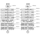
続いて以下では、図5のS12におけるトレーニングの手順、及びS13における複数のアンテナ設定対のリストを求める手順について説明する。図1A及びBに、これらの手順の一例を簡略化したシーケンス図を示す。なお簡単化のため、図1A及びBでは送受信機400を"通信機1"、送受信機500を"通信機2"と表記した。以下では、図1A及びBの簡略シーケンス図と図3の無線通信システムの構成図を連動させて、手順及び動作の説明を行う。
Subsequently, the training procedure in S12 of FIG. 5 and the procedure for obtaining a list of a plurality of antenna setting pairs in S13 will be described below. 1A and 1B are simplified sequence diagrams showing an example of these procedures. For simplification, in FIG. 1A and FIG. 1B, the
一例として、図11及び図12に示すような伝搬環境を考える。図11は通信機1から通信機2に向かってトレーニング信号が伝搬する場合を、図12はその逆の場合を示している。この例では、通信機1及び通信機2並びに反射体62は、壁61に囲まれた室内(2次元)に設置されている。通信機1と通信機2の間で通信に使用可能な伝搬路が、信号1〜4で示した4経路存在するものとする。
As an example, consider a propagation environment as shown in FIGS. 11 shows a case where the training signal propagates from the
図1AのステップS102−1及びS102−2は、通信機1(送受信機400)の送信アンテナのアンテナ設定候補を決定するためのトレーニングである。先ず、S102−1において通信機1は送信動作を行う。このとき、通信機1の記憶回路408、処理演算回路406、制御回路407、アンテナ設定回路404は、互いに連動することによって、送信アンテナ(例えばアンテナアレイ405−1〜M)のアンテナ設定を変更する。これにより、通信機1は、送信アンテナアレイ405−1〜Mのビーム方向を走査する。その状態で、さらに送信回路403も連動する。これにより、通信機1は、送信ビーム方向を走査しながらトレーニング信号を送信する。トレーニング信号は、通信機1(送受信機400)及び通信機2(送受信機500)の間に存在する複数の伝搬路方向の1つと送信ビーム方向が一致した場合に、伝搬路を経て送受信機500へと到来する。
Steps S102-1 and S102-2 in FIG. 1A are trainings for determining antenna setting candidates for the transmission antenna of the communication device 1 (transceiver 400). First, in S102-1, the
このときS102−2において、通信機2(送受信機500)は受信動作を行う。記憶回路508、処理・演算回路506、制御回路513、アンテナ設定回路510は、互いに連動することによって、受信アンテナ(例えばアンテナアレイ511−1〜L)に擬似オムニパターンを発生させる。この状態で、さらに受信回路509も連動する。これにより、通信機2は、固定ビームパターンで、具体的には疑似オムニパターンで、通信機1から送信されるトレーニング信号を受信する。
At this time, in S102-2, the communication device 2 (transceiver 500) performs a reception operation. The
続いて、通信機1と通信機2の役割を交替して同様の処理を実行する。ステップS103−1及びS103−2は、通信機2(送受信機500)の送信アンテナのアンテナ設定候補を決定するためのトレーニングである。即ち、S103−2において、通信機2は送信動作を行い、そのアンテナ設定を変更することによりビーム方向を走査しながらトレーニング信号を送信する。このときS103−1において、通信機1は、擬似オムニパターンを発生させた状態で通信機2からのトレーニング信号を受信する。
Subsequently, the roles of the
次に、ステップS104−1及びS104−2では、通信機2の受信アンテナのアンテナ設定候補を決定するためのトレーニングを行う。S104−1において、通信機1を送信動作させ、送信アンテナに擬似オムニパターンを発生させた状態でトレーニング信号を送信する。このときS104−2において、通信機2を受信動作させ、そのアンテナ設定を変更することによりビーム方向を走査しながら通信機1からのトレーニング信号を受信する。
Next, in steps S104-1 and S104-2, training for determining antenna setting candidates for the receiving antenna of the
続いて、通信機1と通信機2の役割を交替して同様の処理を実行する。即ち、ステップS105−1及びS105−2は、通信機1の受信アンテナのアンテナ設定候補を決定するためのトレーニングである。S105−2において、通信機2を送信動作させ、送信アンテナに擬似オムニパターンを発生させた状態でトレーニング信号を送信する。このときS105−1において、通信機1を受信動作させ、そのアンテナ設定を変更することによりビーム方向を走査しながら通信機2からのトレーニング信号を受信する。
Subsequently, the roles of the
以上のS102〜S105の工程において、4つのトレーニング信号の受信結果が得られた。以下では、これらの受信結果から、4つのアンテナ(通信機1、通信機2それぞれの送信アンテナ及び受信アンテナ)のアンテナ設定候補を決定する手順を述べる。
In the above steps S102 to S105, four training signal reception results were obtained. Hereinafter, a procedure for determining antenna setting candidates for four antennas (the transmission antenna and the reception antenna of each of the
以下では先ず、S106−2において、S102−2におけるトレーニング信号の受信結果を用いて通信機1の送信アンテナのアンテナ設定候補を決定する手順を述べる。
Hereinafter, first, in S106-2, a procedure for determining antenna setting candidates for the transmission antenna of the
S102−2におけるトレーニング信号の受信結果から、通信機1の送信アンテナのアンテナ設定(つまり、送信ビーム方向)と通信機2の受信アンテナにおける受信電力の関係を記述したデータ列を取得する。通信機1の送信アンテナのアンテナ設定は、S102−1におけるトレーニング信号の送信の際に、その情報要素に付加するなどして送信機1から送信機2へ送付するなどしておく。ここでアンテナ設定と受信電力の関係を記述したデータ列を取得するとしたが、受信電力以外の受信信号特性でもよい。受信電力以外の受信信号特性とは例えば、信号電力対雑音電力比(SNR)などである。
From the training signal reception result in S102-2, a data string describing the relationship between the antenna setting of the transmission antenna of the communication device 1 (that is, the transmission beam direction) and the reception power at the reception antenna of the
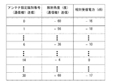
図13に、データ列の一例を示す。この例では、通信機1(送受信機400)のアンテナ設定の識別番号と通信機2(送受信機500)における相対受信電力の関係が記述されている。ここで相対受信電力とは、トレーニングを行った全てのアンテナ設定に対応する受信電力のうち最大のものを0dBとし、その他の受信電力をそれに対する比で表現したものとする。S102−1におけるビーム走査の角度解像度が低い場合、このデータ列から、相対受信電力が予め決めた閾値を超えた複数(または単数)のアンテナ設定を選択し、それらを通信機1の送信アンテナのアンテナ設定候補とすればよい。あるいは、予め検出するアンテナ設定の数を決めておき、相対受信電力値が上位のものから前記設定数までのアンテナ設定を検出するようにしてもよい。これらの処理は、処理・演算回路506で行えばよい。検出したアンテナ設定は、必要であれば記憶回路508へ格納する。
FIG. 13 shows an example of the data string. In this example, the relationship between the identification number of the antenna setting of the communication device 1 (transceiver 400) and the relative received power in the communication device 2 (transceiver 500) is described. Here, the relative received power is the maximum received power corresponding to all the antenna settings for which training has been performed, and the maximum received power is expressed as 0 dB, and the other received powers are expressed as ratios thereto. When the angular resolution of the beam scanning in S102-1 is low, a plurality of (or singular) antenna settings whose relative received power exceeds a predetermined threshold are selected from this data sequence, and these are set as the transmission antennas of the
ただし、S102−1におけるビーム走査の角度解像度が高い場合、前述のような方法では、正しく信号経路に対応したアンテナ設定を検出できない可能性がある。すなわち、高い相対受信電力に対応するビーム方向の周辺方向のアンテナ設定が相対受信電力上位のアンテナ設定となり、信号経路に対応したアンテナ設定として検出してしまう可能性がある。このような場合には、走査した送信機1の送信アンテナのビーム方向(放射角度)の情報を利用し、ピーク検出を行うとよい。そのためには、送信機1の送信アンテナのビーム方向の情報を、送信機1から送信機2へ送付しておく必要がある。この情報は、S102−1におけるトレーニング信号の情報要素などに付加して送付してもよいし、あるいは別途角度情報送付のためのデータを送信してもよい。この場合のデータ列は、例えば図14のようなものになる。この例では、120°の角度範囲を4°の分解能でビーム方向を走査している。このようなデータ列を用いれば、図15のようなプロファイルを作成することが可能となる。このプロファイルを用いてピーク検出を行えば、正しく信号経路に対応したアンテナ設定を検出することが可能になる。この場合も、全てのピークを検出してもよいし、予め検出するアンテナ設定の数を決めておき、相対受信電力値が上位のピークから順に前記設定数までのピークを検出するようにしてもよい。図15に示したプロファイルは概念を示すためのものであり、実際には図14のようなデータ列があればよい。さらに説明のためのものであるので、図15の数値は図14のものと必ずしも一致していない。また、アンテナ設定の識別番号がビーム方向と関連付けられている場合には、角度情報を用いずにピーク検出を行ってもよい。以上の処理は、処理・演算回路506で行えばよい。検出したアンテナ設定は、必要であれば記憶回路508へ格納する。
However, when the angular resolution of the beam scanning in S102-1 is high, there is a possibility that the antenna setting corresponding to the signal path cannot be detected correctly by the method described above. That is, there is a possibility that the antenna setting in the peripheral direction of the beam direction corresponding to the high relative received power becomes the higher antenna setting of the relative received power and detected as the antenna setting corresponding to the signal path. In such a case, peak detection may be performed using information on the beam direction (radiation angle) of the transmission antenna of the scanned
なおここでは説明の簡単化のため、図11及び12のような平面(2次元)の伝搬環境を考えている。従って図15横軸の放射方向も1次元の量となっている。アンテナアレイの次元も1次元を想定している。しかし、本実施の形態は3次元の伝搬環境において、2次元のアンテナアレイを用いる場合にも適用できる。この場合、図14の放射角度の列、及び図15の横軸は2つの角度から成る2次元配列となる。 Here, for simplification of explanation, a plane (two-dimensional) propagation environment as shown in FIGS. 11 and 12 is considered. Therefore, the radial direction of the horizontal axis in FIG. 15 is also a one-dimensional quantity. The dimension of the antenna array is assumed to be one dimension. However, this embodiment can also be applied to a case where a two-dimensional antenna array is used in a three-dimensional propagation environment. In this case, the row of radiation angles in FIG. 14 and the horizontal axis in FIG. 15 form a two-dimensional array composed of two angles.
S106−1において、S103−1におけるトレーニング信号の受信結果を用いて通信機2の送信アンテナのアンテナ設定候補を決定する手順は、上記のS106−2と同様であるので省略する。すなわち、上記のS106−2の手順を通信機1と通信機2の役割を入れ替えて実行すればよい。
In S106-1, the procedure for determining the antenna setting candidate for the transmission antenna of the
次に、S106−2において、S104−2におけるトレーニング信号の受信結果を用いて通信機2の受信アンテナのアンテナ設定候補を決定する手順を述べる。S104−2におけるトレーニング信号の受信結果から、通信機2の受信アンテナのアンテナ設定(つまり受信ビーム方向)と受信電力の関係を記述したデータ列を取得する。以下の処理は、上述したS106−2において通信機1の送信アンテナのアンテナ設定候補を決定する手順と同様である。ただし、ここでは、受信アンテナの受信ビーム方向を走査して得られたトレーニング信号の受信結果(S104−2)を利用する。従って、ビーム走査しているアンテナからトレーニング信号を送信する場合と異なり、アンテナ設定及びビーム方向の情報の送付の必要は無い。またピーク検出を行うために使用するビーム方向の情報は到来角度となる。
Next, in S106-2, a procedure for determining antenna setting candidates for the receiving antenna of the
S106−1において、S105−1におけるトレーニング信号の受信結果を用いて通信機1の受信アンテナのアンテナ設定候補を決定する手順は、上記のS106−2と同様であるので省略する。すなわち、上記のS106−2の手順を通信機1と通信機2の役割を入れ替えて実行すればよい。
In S106-1, the procedure for determining the antenna setting candidate of the receiving antenna of the
以上により、4つのアンテナ(通信機1、通信機2それぞれの送信アンテナ及び受信アンテナ)のアンテナ設定候補が決定された。次に、通信機1及び2は、決定したアンテナ設定候補どうしの総当りのトレーニング(S109からS110)を行うために必要となる情報の送受を行う。すなわち、S107において通信機1から通信機2へ、通信機2の送信アンテナのアンテナ設定候補、及び通信機1の受信アンテナのアンテナ設定候補の総数を送付する。同様に、S108において通信機2から通信機1へ、通信機1の送信アンテナのアンテナ設定候補、及び通信機2の受信アンテナのアンテナ設定候補の総数を送付する。ただし、総当りを行うアンテナ設定候補の総数が予め決まっている場合には、アンテナ設定候補総数の送受の必要はない。また、送信アンテナのアンテナ設定候補の情報は、例えば図16に示すように、決定したアンテナ設定の識別番号とすればよい。この図は、4つのアンテナ設定を検出した場合の例である。4つのアンテナ設定は、例えばこの図のように、トレーニング信号の受信電力の順に整列しておけばよい。
As described above, antenna setting candidates for the four antennas (the transmission antenna and the reception antenna of each of the
S109では、通信機1の送信アンテナと通信機2の受信アンテナのアンテナ設定候補の間で総当りのトレーニングを行う。同様に、S110では、通信機2の送信アンテナと通信機1の受信アンテナのアンテナ設定候補の間で総当りのトレーニングを行う。これらの総当りのトレーニングの詳細な手順については後述する。これらのトレーニングにより、アンテナ設定候補間の正しい組み合わせ(アンテナ設定対)を見出し、さらにそれらを通信品質の良好な順序(例えば、受信電力の大きな順序)に整列する。得られた通信品質順に整列されたアンテナ設定対のデータ列を、アンテナ設定対リストと呼ぶこととする。ここで、リストが通信品質順以外の順序に整列されたとしても、本発明の範囲を逸脱するものではない。アンテナ設定対リストは、例えば図17のようになる。
In S109, brute force training is performed between the antenna setting candidates of the transmission antenna of the
S111では、S110で取得した通信機1の受信アンテナと通信機2の送信アンテナに関するアンテナ設定対リストを、通信機1から通信機2へ送信する。同様に、S112では、S109で取得した通信機1の送信アンテナと通信機2の受信アンテナに関するアンテナ設定対リストを、通信機2から通信機1へ送信する。ただし、S111で送付する情報には、通信機2の送信アンテナ設定の情報が含まれればよく、伝送情報量節約の観点から、図17のうち通信機1の受信アンテナ設定の情報は省略してもよい。同様に、S112で送付する情報には、通信機1の送信アンテナ設定の情報が含まれればよく、通信機2の受信アンテナ設定の情報は省略してもよい。受信したアンテナ設定対リスト、もしくはその一部は、それぞれ記憶回路408、508へ格納される。
In S <b> 111, the antenna setting pair list regarding the reception antenna of the
通信機1及び通信機2は、上述した方法により記憶装置408及び508に格納されたアンテナ設定対の同じ順位のアンテナ設定を選択して通信を開始する(図5のS14及びS15)。例えば、S113において、使用するアンテナ設定順位を通信機1から通信機2へ送付すればよい。ここで送付するアンテナ設定順位は、通信機1の送信アンテナと通信機2の受信アンテナに関する順位、通信機2の送信アンテナと通信機1の受信アンテナに関する順位、の両方であってもよいし、何れか一方であってもよい。また、図中には示していないが、これらの順位の両方、もしくは何れか一方を通信機2から通信機1へ送信するようにしてもよい。また、通信に使用するアンテナ設定順位の順序を予め決めてある場合には、このような使用アンテナ設定順位の送受を省略してもよい。送受されたアンテナ設定対順位に従い、通信機1及び通信機2はアンテナ設定回路404、410、510、504の設定を行い(S114)、通信を開始する(S115)。
The
選択した順位のアンテナ設定対での通信が劣化し、S116、S117においてこれを検知した場合、通信機1及び通信機2は、記憶装置408及び508に格納されたアンテナ設定の中から同じ順位の別のアンテナ設定の対を選択し(図5のS16)、必要に応じて通信品質を確認し(図5のS17)、良好であればそのアンテナ設定対を採用し通信を再開する(S118及びS119)。S118〜S119は、図5の遷移図における、S15からS16の遷移、S16からS17への遷移、及びS17からS15への遷移に対応する。以上の処理においては、アンテナ設定対の選択は、例えばアンテナ設定対の格納順、すなわち総当りトレーニングにおける通信品質(例えば、受信電力)の順に行うとよい。なお、図1Bに示したS116〜S119は、通信機1が送信状態、通信機2が受信状態のときに通信品質の劣化が起こった場合について示している。逆に、通信機1が受信状態、通信機2が送信状態のときに通信品質の劣化が起こった場合は、通信機1と通信機2の役割を入替え、同様の処理を行えばよい。また、例えば、通信機1が送信状態、通信機2が受信状態のときに通信品質の劣化が起こった場合、通信機1の送信アンテナと通信機2の受信アンテナのアンテナ設定対のみを新しいものに入れ替えてもよいし、同時に通信機1の受信アンテナと通信機2の送信アンテナのアンテナ設定対も新しいものに入れ替えてもよい。
When communication with the antenna setting pair of the selected rank deteriorates and is detected in S116 and S117, the
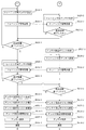
続いて、図1A及びBの簡略化したシーケンス図を用いて説明した動作を、より詳細に説明する。図18A〜図18Cは、図1の簡略化したシーケンス図におけるトレーニング開始(S101)から通信開始(S115)までの手順をより詳細に示したシーケンス図である。以下では、図1A及びBにおいて簡略化した部分について動作を説明する。 Next, the operation described using the simplified sequence diagrams of FIGS. 1A and 1B will be described in more detail. 18A to 18C are sequence diagrams showing in more detail the procedure from the training start (S101) to the communication start (S115) in the simplified sequence diagram of FIG. Hereinafter, the operation of the simplified portion in FIGS. 1A and 1B will be described.
S602〜S605の工程は、図1AにおけるS102の工程の手順の一例を詳細に示したものである。先ず通信機2は、受信アンテナ設定をトレーニング用の値、ここではオムニもしくは擬似オムニパターン生成用の値に設定する(S602−2)。通信機1は、送信アンテナ設定を変更しながら(S603−1)、予め定められた全てのアンテナ設定での信号送信が完了するまで(S605−1)、トレーニング信号の送信を繰り返す(S604−1)。このとき各アンテナ設定に対応する識別番号、もしくはそれと同等のものを送信しておく。通信機2は、そのトレーニング信号、及びアンテナ設定識別番号を受信する(S604−2)。
Steps S602 to S605 show in detail an example of the procedure of step S102 in FIG. 1A. First, the
S606〜S609の工程は、図1AにおけるS103の工程の手順の一例を詳細に示したものである。これは、上記のS602〜S605の工程において、通信機1と通信機2の役割を入れ替えたものと同様の動作であるので、説明は省略する。
Steps S606 to S609 show an example of the procedure of step S103 in FIG. 1A in detail. Since this is the same operation as that in which the roles of the
S610〜S613の工程は、図1AにおけるS104の工程の手順の一例を詳細に示したものである。先ず通信機1は、送信アンテナ設定をトレーニング用の値、ここではオムニもしくは擬似オムニパターン生成用の値に設定し(S610−1)、トレーニング信号を送出する(S612−1)。通信機2は、受信アンテナ設定を変更しながら(S611−2)、予め定められた全てのアンテナ設定での信号受信が完了するまで(S613−2)、トレーニング信号の受信を繰り返す(S612−2)。
Steps S610 to S613 show an example of the procedure of step S104 in FIG. 1A in detail. First, the
S614〜S617の工程は、図1AにおけるS105の工程の手順の一例を詳細に示したものである。この工程は、上記のS610〜S613の工程において、通信機1と通信機2の役割を入れ替えたものと同様の動作であるので、説明は省略する。S620−1、S620−2、S621−1、及びS621−2は、図1AのS107−1、S107−2、S108−1、及びS108−2に対応する。
Steps S614 to S617 show an example of the procedure of step S105 in FIG. 1A in detail. Since this process is the same operation as that in which the roles of the
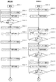
S622〜S626の工程は、図1BにおけるS109の工程の手順の一例を詳細に示したものである。この工程では、S602〜S605の工程におけるトレーニング信号の受信結果を用いてS618−2において決定した通信機1の送信アンテナ設定候補と、S610〜S613の工程におけるトレーニング信号の受信結果を用いてS619−2において決定した通信機2の受信アンテナ設定候補の間で、総当りのトレーニング(通信品質試験)を行う。
Steps S622 to S626 show an example of the procedure of step S109 in FIG. 1B in detail. In this step, the transmission antenna setting candidate of the
先ず通信機1は、送信アンテナ設定候補のうち1つ目のアンテナ設定(例えば、図17におけるアンテナ設定識別番号14)とし(S622−1)、トレーニング信号を送出する(S624−1)。通信機2は、受信アンテナ設定をS619−2において決定した設定候補(例えば、図17におけるアンテナ設定識別番号16、10、2、7)に順次設定しながら(S623−2)、全てのアンテナ設定候補での信号受信が完了するまで(S625−2)、トレーニング信号の受信を繰り返す(S624−2)。以上の手順を、S618−2において決定した通信機1の全ての送信アンテナ設定候補(例えば、図17におけるアンテナ設定識別番号14、20、6、26)について終了するまで繰り返す(S626−1)。
First, the
S627〜S632の工程は、図1BにおけるS110の工程の手順の一例を詳細に示したものである。この工程では、S606〜S609の工程におけるトレーニング信号の受信結果を用いてS618−1において決定した通信機2の送信アンテナ設定候補と、S614〜S617の工程におけるトレーニング信号の受信結果を用いてS619−1において決定した通信機1の受信アンテナ設定候補の間で、総当りのトレーニング(通信品質試験)を行う。この工程は、上記のS622〜S626の工程において、通信機1と通信機2の役割を入れ替えたものと同様の動作であるので、説明は省略する。
Steps S627 to S632 show an example of the procedure of step S110 in FIG. 1B in detail. In this step, the transmission antenna setting candidate of the
ここで、S622〜S626、及びS627〜S632の工程において、送信・受信アンテナの全てのアンテナ設定候補の組み合わせについて総当りのトレーニング(通信品質試験)を行う目的について説明する。 Here, the purpose of performing brute force training (communication quality test) for all combinations of antenna setting candidates for the transmission / reception antennas in the steps S622 to S626 and S627 to S632 will be described.
S602〜S621において4つのアンテナ(通信機1、通信機2それぞれの送信、受信アンテナ)のアンテナ設定候補を決定する工程が高精度に実行可能な場合を考える。伝搬環境として、図11、図12に示したものを考える。これらの図に示した4つの信号は、それぞれ同じ経路を逆向きに伝搬した信号であるから、それぞれの伝搬損失はほぼ等しく、受信電力の信号間の関係は保持される。従ってアンテナ設定候補の検出・決定過程に誤差が無い場合、通信機1の送信アンテナ設定候補と通信機2の受信アンテナ設定候補を、受信電力順に組み合わせれば、通信に利用可能なアンテナ設定対を取得することができる。
Consider a case where the process of determining antenna setting candidates for four antennas (transmission and reception antennas of the
しかし、擬似オムニパターンの精度が悪い、すなわち放射方向によりアンテナ利得に変動がある場合、その他の測定誤差が存在する場合などには、アンテナ設定候補の組合せにエラーが起こる可能性がある。ここでエラーとは、異なる伝搬路に対応するアンテナ設定候補同士が組み合わされてしまうことを意味する。このようなエラーが起こる確率は、先に述べたアンテナ特性の他に、伝搬環境にも依存する。例えば、2つ以上の伝搬路の伝搬損失が近い値を有する場合には発生確率が高くなる。また、アンテナ設定候補の組合せ自体は正しく行われたとしても、アンテナ設定対の順位が正しい受信電力順とは異なるものになる可能性もある。 However, when the accuracy of the pseudo omni pattern is poor, that is, when the antenna gain varies depending on the radiation direction, or when other measurement errors exist, an error may occur in the combination of antenna setting candidates. Here, the error means that antenna setting candidates corresponding to different propagation paths are combined. The probability that such an error occurs depends on the propagation environment in addition to the antenna characteristics described above. For example, the probability of occurrence increases when the propagation loss of two or more propagation paths has a close value. Further, even if the antenna setting candidate combinations themselves are performed correctly, the order of the antenna setting pairs may be different from the correct received power order.
送信・受信アンテナの全てのアンテナ設定候補の組み合わせについて総当りのトレーニング(通信品質試験)を行うことにより、上記のような問題を回避することが可能となる。また一般に、検出・決定されるアンテナ設定候補の数は、S602〜S621におけるビーム方向走査のアンテナ設定数に比較し十分小さく絞り込まれているため、総当りを行ったとしても全トレーニング時間を大幅に増大させるようなことはない。 By performing brute force training (communication quality test) for all combinations of transmission / reception antenna settings, it is possible to avoid the above problems. In general, the number of antenna setting candidates to be detected / determined is sufficiently small compared to the number of antenna settings for beam direction scanning in S602 to S621, so that even if round-robin is performed, the total training time is greatly increased. There is nothing to increase.
ただし、さらに処理時間を抑制するため、アンテナ設定候補の全ての組み合わせについて通信品質の測定を行う上記手順を以下に述べるように変更してもよい。はじめに、アンテナ設定候補を決定した際の受信電力(もしくは他の通信品質)順に、アンテナ設定対を形成する。例えば、通信機1の送信アンテナ設定候補のうち受信電力順位が1位のものと、通信機2の受信アンテナ設定候補のうち受信電力順位が1位のもので対を形成する。そのように形成した複数のアンテナ設定対について通信品質のテストを行い、予め決めておいた通信品質基準を満たさないアンテナ設定対についてのみ、一旦組合せを解除する。そして、通信品質基準を満たさないために組合せを解除されたアンテナ設定候補に関して、全ての組合せについて通信品質試験を行うことにより新たなアンテナ設定対の探索を行う。この後に、上記2回の通信品質テストの結果に基づきアンテナ設定対の優先順位を改めて決定するとよい。このような方法を採ることにより、アンテナ設定候補の決定の際の測定結果に基づいて決定したアンテナ設定対のうち使用可能なものについては、改めて組合せ探索のための総当りによる通信品質測定に含める必要がなくなり、処理時間の短縮が実現できる。このような手順は、アンテナ設定候補の数が多い場合などに有効である。
However, in order to further reduce the processing time, the above procedure for measuring the communication quality for all combinations of antenna setting candidates may be changed as described below. First, antenna setting pairs are formed in the order of received power (or other communication quality) when antenna setting candidates are determined. For example, a pair is formed of the transmission antenna setting candidate of the
次に、通信の遮断等の通信品質の劣化が発生した場合の動作について、図19を用いて説明する。図19は、図5のS15〜S17までの遷移過程における送受信機400及び500の動作を示すシーケンス図である。また以下では、送受信機400(図19の通信機1)が送信動作、送受信機500(図19の通信機2)が受信動作している場合について説明する。
Next, an operation when communication quality deterioration such as communication interruption occurs will be described with reference to FIG. FIG. 19 is a sequence diagram showing operations of the
通信の遮断等の障害が発生した場合、受信動作中の送受信機500は、通信品質の劣化があったことを検知し(S702−2)、送受信機400に通知する(S703−2)。送信動作中の送受信機400は、通信品質の劣化通知を送受信機500から受領するか、データ受信の成功時に送受信機500側から通常の通信で送られてくるACK信号が受信されないことによって、通信の遮断(もしくは通信状態の悪化)があったと認識する。このとき、送受信機400及び500は、それぞれが有するデータベース(アンテナ設定対リスト)から、それぞれ次候補のアンテナ設定を取得する(S704−1、2)。
When a failure such as communication interruption occurs, the
ステップS705−1では、送受信機400が、次候補のアンテナ設定をアンテナ設定回路404に設定する。同様に、ステップS705−2では、送受信機500が、次候補のアンテナ設定をアンテナ設定回路510に設定する。この後、送受信機400及び500は、通信を再開する(S706−1、2)。通信再開後、送受信機500は通信品質を確認し(S707−2)、良好であれば通信を継続し、良好でなければアンテナ設定の変更通知を送出する(S708−2)。送受信機400は、アンテナ設定の変更通知を受領した場合又は送受信機500からACK信号が受信できない場合(S709−1)を除き、そのまま通信を継続する。もしそうでなければ、送受信機400及び500は、次のアンテナ設定対候補がある限り、次候補での通信を試みる(S710−1、2)。もし、記憶回路408及び508に記録された何れのアンテナ設定対候補でも通信品質の改善が得られず、次候補が無くなった場合、送受信機400及び500は、トレーニングに戻る。
In step S705-1, the
本実施の形態で述べた手順は、一例に過ぎない。例えば、各工程の順序、各種処理・演算を行う通信機、並びに送受する情報の内容などには自由度があり、これらのうちいずれかが異なる場合でも本実施の形態及び本発明の範囲を逸脱するものではない。また説明においては、便宜上、複数の処理の集合を、例えば図1AのS104−1のように一つの工程に纏めてある。これらの工程を構成する処理の順序が、工程間で入替わるようなことがあってもよい。例えば、図1AのS104を構成する各処理と、S105を構成する各処理が時間的に交互となるような場合も、本実施の形態及び本発明の範囲を逸脱するものではない。 The procedure described in this embodiment is merely an example. For example, there is a degree of freedom in the order of each process, a communication device that performs various processes / calculations, and the content of information to be transmitted and received, and even if any of these is different, it deviates from the scope of this embodiment and the present invention Not what you want. In the description, for convenience, a set of a plurality of processes is combined into one process, for example, S104-1 in FIG. 1A. The order of the processes constituting these processes may be changed between the processes. For example, even when each process constituting S104 of FIG. 1A and each process constituting S105 are temporally alternated, it does not depart from the scope of the present embodiment and the present invention.
本実施の形態によれば、無線通信の途絶などの通信品質の劣化が発生した場合には、予め生成されている他のアンテナ設定対候補を選択することによって、速やかに通信を再開することができる。言い換えると、本実施の形態では、通信品質の劣化が発生するたびにトレーニングを改めて行う必要がないので、短時間で新しいアンテナ設定を決めることが可能になる。本実施の形態のトレーニング時間はS602〜S621におけるビーム方向走査のアンテナ設定数などに依存し、長くなる場合もあり得る。しかし一般に、トレーニングは通信開始前に実行されるため、通信途中での遮断からの復帰に比べて長い時間が許容されるので、支障は小さい。 According to the present embodiment, when communication quality degradation such as wireless communication interruption occurs, communication can be resumed quickly by selecting another antenna setting pair candidate generated in advance. it can. In other words, in the present embodiment, it is not necessary to perform training again each time communication quality deteriorates, so that a new antenna setting can be determined in a short time. The training time in this embodiment depends on the number of antenna settings for beam direction scanning in S602 to S621, and may be longer. However, in general, since training is performed before the start of communication, a longer time is allowed as compared with the return from interruption in the middle of communication, so the trouble is small.
また本実施の形態では、アンテナ設定対を決定するための手順として、アンテナ設定候補の各組み合わせについて総当たりの通信品質測定を行い、測定結果に基づいてアンテナ設定対を決定する具体例を示した。上述したように、擬似オムニパターンの精度が悪い、すなわち放射方向によりアンテナ利得に変動がある場合、その他の測定誤差が存在する場合などには、アンテナ設定候補の組合せにエラーが起こる可能性がある。これに対して、アンテナ設定候補間での総当りのトレーニングを行うことによって、アンテナ設定候補の検出・決定工程において擬似オムニパターンの精度が悪い場合や、その他の測定誤差が存在するような場合にも、正しい組み合わせと順位のアンテナ設定対を取得することが可能になる。 Further, in the present embodiment, as a procedure for determining an antenna setting pair, a specific example is shown in which a brute force communication quality measurement is performed for each combination of antenna setting candidates and an antenna setting pair is determined based on the measurement result. . As described above, when the accuracy of the pseudo omni pattern is poor, that is, when the antenna gain varies depending on the radiation direction, or when other measurement errors exist, an error may occur in the combination of antenna setting candidates. . On the other hand, by performing brute force training between antenna setting candidates, when the accuracy of the pseudo omni pattern is poor or other measurement errors exist in the antenna setting candidate detection / determination process Also, it becomes possible to obtain an antenna setting pair of the correct combination and order.
以下に、この方法が屋内のミリ波、あるいは直進性が高くなる概ね10GHz以上のマイクロ波で有効である理由について補足的に説明する。無線通信に供することのできる伝搬路は限られている。つまり、直接波と、壁、窓、什器などの特定の物体からの反射波である。したがって、各伝搬路の放射すべき角度、あるいは受信すべき角度は、それぞれの波(信号)によって大きく異なっている。一方、例えば2.4GHzのマイクロ波帯のような直進性の低い伝搬路を使用する場合は、多重散乱や回折による効果を考慮する必要があるため、通常は指向性のあるアンテナは用いられない。このため、概ね10GHz以上のマイクロ波通信及びミリ波通信と2.4GHz程度のマイクロ波通信とでは、状況が異なる。なお、2.4GHzのマイクロ波通信の分野でも、干渉を除去することを目的として、指向性のある適応アンテナの開発例がある。しかしながら、適応型の指向性アンテナを使用する場合でも、2.4GHz帯では回折の効果が期待できるため、直接波の角度又はそれに近い角度で良好な通信品質を確保しやすい。 Below, the reason why this method is effective for indoor millimeter waves or microwaves of approximately 10 GHz or higher, which increases straightness, will be supplementarily described. A propagation path that can be used for wireless communication is limited. That is, direct waves and reflected waves from specific objects such as walls, windows, and fixtures. Therefore, the angle to be radiated or the angle to be received in each propagation path is greatly different depending on each wave (signal). On the other hand, when using a propagation path with low rectilinearity such as a 2.4 GHz microwave band, it is necessary to consider the effects of multiple scattering and diffraction. . For this reason, the situation differs between microwave communication and millimeter wave communication of approximately 10 GHz or more and microwave communication of approximately 2.4 GHz. In the field of 2.4 GHz microwave communication, there is an example of developing an adaptive antenna having directivity for the purpose of eliminating interference. However, even when an adaptive directional antenna is used, since a diffraction effect can be expected in the 2.4 GHz band, it is easy to ensure good communication quality at an angle of a direct wave or an angle close thereto.
ミリ波帯におけるビームフォーミングを用いた屋内通信においては、次の性質を考慮する必要がある。前述の通り、直接波以外の反射波の数は限られている。また、特定の直接波または反射波が障害物(例えば人体)によって遮られた場合でも、遮蔽された特定の波と他の波とは無相関である。従って、本実施の形態で述べたように、ミリ波通信システムでは、最も通信状態の良いビーム方向で通信を行いながら、予備のビーム方向を確保することができる。一方、概ね10GHz未満の周波数の場合は、多重反射や回折の通信品質に対する寄与が大きい。よって、仮に指向性のあるアンテナを用いたとしても、障害物の有無によって予備のビーム方向の伝搬状況も変化してしまう。つまり、障害物が存在しない場合には良好であった予備のビーム方向からの受信状態が、障害物の存在によって変動する可能性が高い。したがって、2.4GHzのマイクロ波通信などでは、本発明の効果を得ることが困難である。 In indoor communication using beam forming in the millimeter wave band, it is necessary to consider the following properties. As described above, the number of reflected waves other than direct waves is limited. Even when a specific direct wave or reflected wave is blocked by an obstacle (for example, a human body), the blocked specific wave and other waves are uncorrelated. Therefore, as described in the present embodiment, in the millimeter wave communication system, a spare beam direction can be secured while performing communication in a beam direction having the best communication state. On the other hand, when the frequency is less than about 10 GHz, the contribution to the communication quality of multiple reflection and diffraction is large. Therefore, even if a directional antenna is used, the propagation state of the spare beam direction changes depending on the presence or absence of an obstacle. That is, there is a high possibility that the reception state from the spare beam direction, which is good when there is no obstacle, varies depending on the presence of the obstacle. Therefore, it is difficult to obtain the effect of the present invention in 2.4 GHz microwave communication or the like.
また、ミリ波通信においては、局所的な反射による伝搬路ができることがある。その様子を図25A及びBに示す。図25Aには、送受信機81及び82があり、ビームフォーミングでの伝搬路として直接波A、局所的な反射波B、遠くの経路での反射波Cがあると仮定する。直接波A、局所的な反射波Bは、例えば人体による遮蔽によって同時に遮断される可能性がある。この問題に対して特許文献1は、既に優先順位が付与されたビーム方向近傍のビーム方向には優先順位を付与しない、もしくはその優先順位を下げる技術を開示している。ここまでの説明では、アンテナ設定対に対して受信電力順(もしくは他の通信品質順)に優先順位を付与する例を示したが、この受信電力の基準に加えビーム候補(アンテナ設定候補)間の角度の関係を優先順位の付与において加味してもよい。本実施の形態においては、それぞれの通信機におけるビーム候補間の角度関係の情報が取得済みであるから、これが可能となる。
In millimeter wave communication, a propagation path by local reflection may be formed. This is shown in FIGS. 25A and 25B. In FIG. 25A, there are
以上の説明においては、一部の工程における通信機のアンテナの放射パターンとして、オムニもしくは擬似オムニパターンを使用した。しかし、オムニもしくは擬似オムニパターンの発生が困難な場合には、他の固定ビームパターンで替えてもよい。ただし、十分広い角度範囲にわたりアンテナ利得を有するパターンを用いることが好ましい。もしアンテナの放射パターンが既知である場合には、図1AのS102〜S105において取得した受信データから固定ビームパターンのアンテナ利得の方向依存性の影響を除去する処理を追加してもよい。その際、必要であれば、固定ビームパターンのアンテナ利得の方向依存性を記述したデータ列を通信機間で送受すればよい。 In the above description, an omni or pseudo omni pattern is used as the radiation pattern of the antenna of the communication device in some processes. However, when it is difficult to generate an omni or pseudo omni pattern, another fixed beam pattern may be used. However, it is preferable to use a pattern having an antenna gain over a sufficiently wide angle range. If the radiation pattern of the antenna is known, a process for removing the influence of the direction dependence of the antenna gain of the fixed beam pattern from the received data acquired in S102 to S105 in FIG. 1A may be added. At that time, if necessary, a data string describing the direction dependence of the antenna gain of the fixed beam pattern may be transmitted and received between the communication devices.
以上の説明においては、2つの通信機の間におけるビームフォーミング動作を説明した。このような動作は、しばしば3つ以上の通信機から構成される系において、そのうちの2つの通信機間で行われる。この系には、ピコネットコーディネータやアクセスポイントなどと呼ばれる特別な権限を与えられた通信機が通常存在する。3つ以上の通信機のうち、どの2つの通信機の間でビームフォ−ミング動作を行うかは、通常このピコネットコーディネータやアクセスポイントと呼ばれる通信機からの命令により決定すればよい。ピコネットコーディネータやアクセスポイントは、一般の通信機からの要求を受け、この命令を発すればよい。 In the above description, the beam forming operation between the two communication devices has been described. Such an operation is often performed between two communication devices in a system including three or more communication devices. In this system, there are usually communicators with special privileges called piconet coordinators and access points. Of the three or more communication devices, which two communication devices perform the beam forming operation may be determined by a command from a communication device normally called a piconet coordinator or an access point. The piconet coordinator or access point may issue a command in response to a request from a general communication device.
また本実施の形態においては、2つの通信機の間で同様の処理を役割を入替えて実行する。このとき、どちらの通信機がどちらの役割を先に行うのかについても、例えば、ピコネットコーディネータやアクセスポイントと呼ばれる通信機からの命令で決定すればよい。 Further, in the present embodiment, the same processing is executed by switching roles between two communication devices. At this time, which communication device performs which role first may be determined by a command from a communication device called a piconet coordinator or an access point, for example.
また、上記の説明においては、"通信機を受信動作させる"、"オムニ(無指向性)もしくは擬似オムニ(擬似無指向性)パターンを発生させる"といった表現を用いたが、これらの処理は、通常、送受信機400及び500の処理・演算回路406及び506などに予め組み込まれたプログラムに従い実行すればよい。
In the above description, expressions such as “activate the communication device”, “generate an omni (omnidirectional) or pseudo omni (pseudo omnidirectional) pattern” are used. Usually, it may be executed in accordance with a program incorporated in advance in the processing /
<第2の実施の形態>
本発明における第2の実施の形態を、図6に示した遷移図を用いて説明する。なお本実施の形態に係る無線通信システムの構成は、例えば図3に示したものと同様とすればよい。図6のS11〜S17の各状態とこれらの間での遷移条件は、第1の実施の形態で述べた図5の同一符号のものと同様である。このため、S11〜S17に関する詳細な説明は省略する。<Second Embodiment>
A second embodiment of the present invention will be described with reference to the transition diagram shown in FIG. The configuration of the wireless communication system according to the present embodiment may be the same as that shown in FIG. 3, for example. The states of S11 to S17 in FIG. 6 and the transition conditions between them are the same as those in FIG. 5 described in the first embodiment. For this reason, the detailed description regarding S11-S17 is abbreviate | omitted.
図6のS18では、通信継続中の状態(S15)から遷移して付加的なトレーニングを行う。付加トレーニングは、周期的に実行してもよいし、送受信データが存在しないアイドル期間に適宜実行してもよい。 In S18 of FIG. 6, a transition is made from the communication continuing state (S15), and additional training is performed. The additional training may be executed periodically, or may be executed as appropriate during an idle period in which transmission / reception data does not exist.
S18では、処理・演算回路406及び506が、複数のアンテナ設定対の候補を再計算する。処理・演算回路406及び506は、再計算によって得られた複数のアンテナ設定対によって、記憶装置408及び508内のアンテナ設定対リストを更新する(S19)。
In S18, the processing /
本実施の形態においては、予備のビーム方向(アンテナ設定)に対する状況を付加トレーニングによって周期的又は適宜調査し、アンテナ設定対リストを更新する。これにより、本実施の形態にかかる無線通信システムは、常に最新のアンテナ設定対リストを確保することができる。なお付加トレーニング(S18)は、通信の合間に分割して行ってもよい。これにより、長い時間通信を止める必要がなくなる。また、通信が途絶した場合、または通信品質が劣化した場合には、極めて短時間での復帰が求められるが、この付加トレーニングにはそれほどの即時性は必要ないため、トレーニング時間への制約は強くない。 In the present embodiment, the situation with respect to the spare beam direction (antenna setting) is periodically or appropriately investigated by additional training, and the antenna setting pair list is updated. Thereby, the radio | wireless communications system concerning this Embodiment can always ensure the newest antenna setting pair list. Note that the additional training (S18) may be divided between communications. This eliminates the need to stop communication for a long time. In addition, when communication is interrupted or communication quality deteriorates, it is required to return in a very short time, but this additional training does not require much immediateness, so there is a strong restriction on training time. Absent.
また、この付加トレーニングにおいては初期のトレーニングに比べても即時性の要求が弱い場合が多いので、アンテナ設定を変更することによりビーム方向を走査する際の角度分解能を上げて走査を実施してもよい。これにより、より良好な通信品質を実現するアンテナ設定対の探索が可能となる。 Also, in this additional training, the immediacy requirement is often weaker than in the initial training. Therefore, even if scanning is carried out by increasing the angular resolution when scanning the beam direction by changing the antenna setting. Good. As a result, it is possible to search for an antenna setting pair that realizes better communication quality.
また、付加トレーニングにおけるビーム方向の走査は、初期トレーニングの際に求めた各アンテナ設定対に対応したビーム方向の周囲のみに限定して行ってもよい。これにより良好な通信品質を実現するアンテナ設定対の探索が、より短時間で実現可能となる。 Further, the scanning in the beam direction in the additional training may be limited to only around the beam direction corresponding to each antenna setting pair obtained in the initial training. This makes it possible to search for an antenna setting pair that realizes good communication quality in a shorter time.
なお上記の説明における付加トレーニングにおいては、アンテナ設定候補の決定からアンテナ設定対リストの作成まで、すなわちトレーニング全体(S12及びS13に相当する部分)を実施していた。しかし、S13にて取得したアンテナ設定対の全て、もしくはその一部について通信品質試験を行い、その結果に基づいて、アンテナ設定対リストの更新(アンテナ設定対リスト中のアンテナ設定対の順位の入替え、一部のアンテナ設置対の削除等)を行う形としてもよい。あるいは、S12において決定したアンテナ設定候補の全て、もしくはその一部に関し、通信機間での総当りの通信品質試験(図1BのS109、S110に相当)を行い、その結果に基づいて、アンテナ設定対リストの更新を行う形としてもよい。 In the additional training in the above description, the entire training (part corresponding to S12 and S13) is performed from the determination of the antenna setting candidate to the creation of the antenna setting pair list. However, a communication quality test is performed on all or part of the antenna setting pairs acquired in S13, and the antenna setting pair list is updated based on the result (the order of the antenna setting pairs in the antenna setting pair list is changed). , Deletion of some antenna installation pairs, etc.) may be performed. Alternatively, a round robin communication quality test (corresponding to S109 and S110 in FIG. 1B) is performed for all or part of the antenna setting candidates determined in S12, and antenna setting is performed based on the result. The pair list may be updated.
また、付加トレーニングにより行われたアンテナ設定対リストの更新結果は、通信に使用中のアンテナ設定対に更新後すぐに反映させてもよいし、あるいは、次に通信品質の劣化によりS15からS16への遷移が起こった機会に初めて反映されるようにしてもよい。 The update result of the antenna setting pair list performed by the additional training may be reflected immediately after the update to the antenna setting pair used for communication, or from S15 to S16 due to the deterioration of the communication quality. It may be reflected for the first time on the occasion of the transition.
<第3の実施の形態>
本発明における第3の実施の形態を、図7に示した遷移図を用いて説明する。本実施の形態にかかる無線通信システムの構成は、例えば図3に示したものと同様とすればよい。また、図7のS11〜S17の各状態とこれらの間(S16〜S17間を除く)での遷移条件は、第1の実施の形態で述べた図5の同一符号のものと同様である。このため、S11〜S17に関する詳細な説明は省略する。<Third Embodiment>
A third embodiment of the present invention will be described with reference to the transition diagram shown in FIG. The configuration of the wireless communication system according to the present embodiment may be the same as that shown in FIG. 3, for example. Also, the transition conditions between the states of S11 to S17 in FIG. 7 and between these (except between S16 to S17) are the same as those of the same reference numerals in FIG. 5 described in the first embodiment. For this reason, the detailed description regarding S11-S17 is abbreviate | omitted.
本実施の形態では、通信の途絶などの通信品質の劣化が発生した場合、アンテナ設定対リストに記録された次候補のアンテナ設定対を選択するとともに(S16)、その状態で微調整を行う(S20)。この微調整とは、時間をかけずに最適ビーム(アンテナ設定)を探索する方法を指す。具体的には、アンテナ設定を僅かに変更することでビーム方向を僅かに変化させ通信品質が良くなるように調整を行えばよい。また、特許文献4に記載された"Beam Tracking"など簡略化されたビーム探索手順を適用してもよい。また、初期のトレーニングと同様の処理を、新たに選択したアンテナ設定対に対応するビーム方向の周囲で、初期トレーニングよりも角度分解能を上げて実施してもよい。
In this embodiment, when communication quality degradation such as communication interruption occurs, the next candidate antenna setting pair recorded in the antenna setting pair list is selected (S16), and fine adjustment is performed in that state (S16). S20). This fine adjustment refers to a method of searching for an optimum beam (antenna setting) without taking time. Specifically, adjustment may be made so that the communication quality is improved by slightly changing the antenna setting to slightly change the beam direction. Also, a simplified beam search procedure such as “Beam Tracking” described in
例えば、第1の実施の形態で詳細に述べたように、大きな受信電力に対応したアンテナ設定対から小さな受信電力に対応したアンテナ設定対に順に移っていく場合、徐々に受信電力が小さくなり、精度が悪くなっていく可能性がある。そこで、遮蔽があって受信電力が小さくなった状態で、例えば受信時の利得調整を行い、最適な状態で微調整を行うことにより、高精度で安定した伝送が可能なアンテナ設定対が見出せるという効果が得られる。 For example, as described in detail in the first embodiment, when sequentially moving from an antenna setting pair corresponding to a large reception power to an antenna setting pair corresponding to a small reception power, the reception power gradually decreases, The accuracy may go down. Therefore, it is possible to find an antenna setting pair capable of high-accuracy and stable transmission by performing gain adjustment at the time of reception, for example, and performing fine adjustment in an optimal state in a state where reception power is reduced due to shielding. An effect is obtained.
<第4の実施の形態>
本発明における第4の実施の形態を、図8に示した遷移図を用いて説明する。本実施の形態にかかる無線通信システムの構成は、例えば図3に示したものと同様とすればよい。また、図8のS11〜S17の各状態とこれらの間(S13〜S14間を除く)での遷移条件は、第1の実施の形態で述べた図5の同一符号のものと同様である。このため、S11〜S17に関する詳細な説明は省略する。<Fourth embodiment>
A fourth embodiment of the present invention will be described with reference to the transition diagram shown in FIG. The configuration of the wireless communication system according to the present embodiment may be the same as that shown in FIG. 3, for example. Further, the states of S11 to S17 in FIG. 8 and the transition conditions between these states (except between S13 to S14) are the same as those of the same reference numerals in FIG. 5 described in the first embodiment. For this reason, the detailed description regarding S11-S17 is abbreviate | omitted.
本実施の形態では、S13において一旦アンテナ設定対リストを取得後、通信開始前にリストに含まれる全て、もしくは一部のアンテナ設定対に対し微調整を行う(S21)。微調整とは例えば、リストに含まれるアンテナ設定対に対応するビーム方向の周囲で、S12におけるトレーニングに比較し高い角度解像度で、アンテナ設定を調整することを指す。その後、微調整を行ったアンテナ設定対リストからアンテナ設定対を選択し(S14)、通信を開始する(S15)。 In the present embodiment, after obtaining the antenna setting pair list once in S13, fine adjustment is performed on all or some of the antenna setting pairs included in the list before starting communication (S21). For example, the fine adjustment refers to adjusting the antenna setting around the beam direction corresponding to the antenna setting pair included in the list with a higher angular resolution than the training in S12. Thereafter, an antenna setting pair is selected from the antenna setting pair list that has been finely adjusted (S14), and communication is started (S15).
本実施の形態によれば、アンテナ設定対リストに含まれる各アンテナ設定対を使用する際の送受信機400及び500の間の通信品質を向上させることができる。また、通信開始に先立って予め微調整を行うため、通信途絶が発生した後のアンテナ設定対の変更時に微調整を行う場合に比べて、通信途絶時間の短縮を図ることができる。
According to the present embodiment, it is possible to improve the communication quality between the
<第5の実施の形態>
本発明における第5の実施の形態を、図9に示した遷移図を用いて説明する。本実施の形態にかかる無線通信システムの構成は、例えば図3に示したものと同様とすればよい。また、図9のS11〜S17の各状態とこれらの間(S13〜S14間、S16〜S17間を除く)での遷移条件は、第1の実施の形態で述べた図5の同一符号のものと同様である。このため、S11〜S17に関する詳細な説明は省略する。<Fifth embodiment>
A fifth embodiment of the present invention will be described with reference to the transition diagram shown in FIG. The configuration of the wireless communication system according to the present embodiment may be the same as that shown in FIG. 3, for example. In addition, the transition conditions between the states S11 to S17 in FIG. 9 and between them (except between S13 to S14 and between S16 to S17) are the same as those in FIG. 5 described in the first embodiment. It is the same. For this reason, the detailed description regarding S11-S17 is abbreviate | omitted.
第2乃至第4の実施の形態において第1の実施の形態に付加した手順は、それらのうち複数を同時に適用することも可能である。本実施の形態は、全ての手順(S18及びS19、S20、S22)を同時に付加した例である。 A plurality of the procedures added to the first embodiment in the second to fourth embodiments can be applied simultaneously. This embodiment is an example in which all the procedures (S18 and S19, S20, S22) are added simultaneously.
<第6の実施の形態>
本発明における第6の実施の形態を、図10に示した遷移図を用いて説明する。本実施の形態にかかる無線通信システムの構成は、例えば図3に示したものと同様とすればよい。また、図10のS11〜S15の各状態とこれらの間(S15〜S11間を除く)での遷移条件は、第1の実施の形態で述べた図5の同一符号のものと同様である。このため、S11〜S15に関する詳細な説明は省略する。<Sixth Embodiment>
A sixth embodiment of the present invention will be described using the transition diagram shown in FIG. The configuration of the wireless communication system according to the present embodiment may be the same as that shown in FIG. 3, for example. Moreover, the transition conditions between each state of S11 to S15 in FIG. 10 (except between S15 to S11) are the same as those of the same reference numerals in FIG. 5 described in the first embodiment. For this reason, the detailed description regarding S11-S15 is abbreviate | omitted.
第1乃至第5の実施の形態においては、通信中(S15)において通信途絶や通信品質劣化が起こった場合、アンテナ設定対リストから別のアンテナ設定対を選択し(S16)、必要であれば微調整を行い(S20)、通信品質確認(S17)後、通信を再開する(S15)、としていた。しかし本実施の形態のように、アンテナ設定対リストから一つの設定対を選択し(S14)、通信中(S15)に通信途絶や通信品質劣化が起こった場合には再度トレーニング(S12)を行うようにしてもよい。S14において、アンテナ設定対リストから一つの設定対を選択する際には、S12及びS13のトレーニングにおいて最も受信電力の大きい(もしくは、他の通信品質指標が高い)設定対を選択するとよい。 In the first to fifth embodiments, when communication interruption or communication quality deterioration occurs during communication (S15), another antenna setting pair is selected from the antenna setting pair list (S16), and if necessary, Fine adjustment was performed (S20), and after communication quality confirmation (S17), communication was resumed (S15). However, as in the present embodiment, one setting pair is selected from the antenna setting pair list (S14), and when communication is interrupted or communication quality deteriorates during communication (S15), training (S12) is performed again. You may do it. In S14, when one setting pair is selected from the antenna setting pair list, it is preferable to select a setting pair having the largest received power (or other communication quality index is high) in the training of S12 and S13.
この実施の形態においては、予備のアンテナ設定対を備蓄しておき、通信途絶や通信品質劣化が起こった場合には、高速にアンテナ設定対を切り替えて通信を再開できる、という効果は失われる。しかし、実施の形態1で述べたように本発明には、アンテナ設定候補の検出・決定工程において擬似オムニパターンの精度が悪い場合や、その他の測定誤差が存在するような場合にも、アンテナ設定候補間での総当りのトレーニングを行うことによって、正しい組み合わせと順位のアンテナ設定対を取得することが可能になる、というもう一つの効果がある。従って、備蓄した予備のアンテナ設定対を使用しない本実施の形態のような場合おいても、本発明は有効である。 In this embodiment, the effect that the spare antenna setting pair is stored and communication can be resumed by switching the antenna setting pair at high speed is lost when communication interruption or communication quality degradation occurs. However, as described in the first embodiment, the present invention includes the antenna setting even when the accuracy of the pseudo omni pattern is poor in the antenna setting candidate detection / determination process or when other measurement errors exist. By performing brute force training between candidates, there is another effect that it is possible to obtain an antenna setting pair having a correct combination and order. Therefore, the present invention is effective even in the case of the present embodiment in which the stored spare antenna setting pair is not used.
<第7の実施の形態>
本発明における第7の実施の形態を、図20A〜図20Bに示したシーケンス図を用いて説明する。本シーケンス図は、図18A〜図18Bに示したものの変形であり、図20Bの工程終了後は、図18Cの工程を実行すればよい。<Seventh embodiment>
A seventh embodiment of the present invention will be described using the sequence diagrams shown in FIGS. 20A to 20B. This sequence diagram is a modification of that shown in FIGS. 18A to 18B. After the process of FIG. 20B is completed, the process of FIG. 18C may be executed.
第1の実施の形態においては、各アンテナのアンテナ設定候補を決定するための工程(図1AのS102〜S105、図18A及びBのS602〜S617)において、擬似オムニパターンを使用している。しかし、使用するアンテナの種類や構造、周波数帯などの条件によっては、所望の角度範囲にわたって擬似オムニパターンを実現することが困難な場合もある。そのような場合には、図1AのS102−2、S103−1、S104−1、S105−2の一部、もしくは全てにおいて発生させる擬似オムニパターンを、適当な複数の角度範囲に分割し、分割された各角度範囲に対して、S102、S103、S104、S105の工程の一部、もしくは全てを複数回繰り返してもよい。 In the first embodiment, a pseudo omni pattern is used in the steps for determining antenna setting candidates for each antenna (S102 to S105 in FIG. 1A and S602 to S617 in FIGS. 18A and B). However, depending on conditions such as the type and structure of the antenna used and the frequency band, it may be difficult to realize a pseudo omni pattern over a desired angle range. In such a case, the pseudo omni pattern generated in part or all of S102-2, S103-1, S104-1, and S105-2 in FIG. 1A is divided into a plurality of appropriate angular ranges. Some or all of the steps S102, S103, S104, and S105 may be repeated a plurality of times for each angle range.
図20A〜図20Bに示したシーケンス図は、図1AのS104、S105の工程をそれぞれ2回に分割した場合の例である。図18A〜図18Bと比較すると、S639〜S642、及びS643〜S646の工程が付加されている。S610−1とS639−1で設定する2つの擬似オムニパターンで、通信機1の送信アンテナの所望の角度範囲がカバーされる。S619−2において通信機2の受信アンテナ設定候補を決定する際には、S612−2及びS641−2で取得した両方の受信信号データを使用すればよい。
同様に、S614−2とS643−2で設定する2つの擬似オムニパターンで、通信機2の送信アンテナの所望の角度範囲がカバーされる。S619−1において通信機1の受信アンテナ設定候補を決定する際には、S616−1及びS645−1で取得した両方の受信信号データを使用すればよい。The sequence diagrams shown in FIGS. 20A to 20B are examples in which the processes of S104 and S105 in FIG. 1A are each divided twice. Compared with FIGS. 18A to 18B, steps S639 to S642 and S643 to S646 are added. The two pseudo omni patterns set in S610-1 and S639-1 cover the desired angular range of the transmission antenna of the
Similarly, a desired angular range of the transmission antenna of the
上述の"所望の角度範囲"とは、例えば通信に使用する全ての伝搬路を含む角度範囲(方向範囲)を意味する。このように複数の擬似オムニパターンの組合せで必要な角度範囲をカバーする方法自体は、非特許文献5に開示されている。 The above-mentioned “desired angle range” means an angle range (direction range) including, for example, all propagation paths used for communication. Non-patent document 5 discloses a method for covering a necessary angle range with a combination of a plurality of pseudo omni patterns.
<第8の実施の形態>
本発明における第8の実施の形態を、図21A〜図21Bに示したシーケンス図を用いて説明する。これらのシーケンス図は、図18A〜図18Bに示したシーケンス図の変形である。図21Bの工程終了後は、図18Cの工程を実行すればよい。<Eighth Embodiment>
The eighth embodiment of the present invention will be described with reference to the sequence diagrams shown in FIGS. 21A to 21B. These sequence diagrams are modifications of the sequence diagrams shown in FIGS. 18A to 18B. After the process of FIG. 21B is completed, the process of FIG. 18C may be executed.
第1の実施の形態の末尾でも述べたように、本発明を実施するに際しては、各工程の順序、各種処理・演算を行う通信機、送受する情報の内容、などには多様な自由度がある。本実施の形態は、そのような変形の一例を示すものである。以下、図21A〜図21Bのシーケンス図に沿って動作を説明する。 As described at the end of the first embodiment, when implementing the present invention, there are various degrees of freedom in the order of each process, the communication device that performs various processes and operations, the content of information to be transmitted and received, and the like. is there. The present embodiment shows an example of such a modification. The operation will be described below with reference to the sequence diagrams of FIGS. 21A to 21B.
先ず通信機2は、受信アンテナ設定をトレーニング用の値、ここではオムニもしくは擬似オムニパターン生成用の値に設定する(S602−2)。通信機1は、送信アンテナ設定を変更しながら(S603−1)、予め定められた全てのアンテナ設定での信号送信が完了するまで(S605−1)、トレーニング信号の送信を繰り返す(S604−1)。通信機2は、そのトレーニング信号を受信する(S604−2)。
First, the
続いて通信機2は、S604−2において受信した測定データを通信機1へフィードバックする(S647−2)。送信機1はこれを受信し(S647−1)、この測定データを用いて自身の送信アンテナ設定候補を決定する。
Subsequently, the
S606〜S650においては、以上の工程(S602〜S648)の手順を、通信機1と通信機2の役割を入れ替えて行う。
In S606-S650, the procedure of the above process (S602-S648) is performed by exchanging the roles of the
S610〜S613の工程は第1の実施の形態(図18B)と全く同じであるが、本実施の形態では、その直後に通信機2が、S612−2で受信した測定データを用いて自身の受信アンテナ設定候補の決定処理を行うようにしている(S651−2)。
The steps S610 to S613 are exactly the same as those in the first embodiment (FIG. 18B). However, in this embodiment, the
S614〜S619においては、以上の工程(S610〜S651)の手順を、通信機1と通信機2の役割を入れ替えて行う。
In S614-S619, the procedure of the above process (S610-S651) is performed by exchanging the roles of the
本実施の形態の場合、S652及びS653で送受する情報の内容も第1の実施の形態とは異なってくる。本実施の形態では、アンテナ設定候補の決定は全て各アンテナが搭載された通信機自身で行われている。従って、例えば図16のようなアンテナ設定候補の送受の必要はない。ただし、アンテナ設定候補どうしの総当りのトレーニングを行うために、各通信機自身のアンテナ設定候補の総数を他方の通信機へ通知しておく必要がある。すなわち、S652において、通信機1から通信機2へ、通信機1の送信及び受信アンテナのアンテナ設定候補の総数を送付する。S653においては逆に、通信機2から通信機1へ、通信機2の送信及び受信アンテナのアンテナ設定候補の総数を送付する。
In the case of the present embodiment, the contents of information transmitted and received in S652 and S653 are also different from those in the first embodiment. In the present embodiment, all antenna setting candidates are determined by the communication device itself equipped with each antenna. Therefore, there is no need to transmit / receive antenna setting candidates as shown in FIG. However, in order to perform brute force training between antenna setting candidates, it is necessary to notify the other communication device of the total number of antenna setting candidates of each communication device itself. That is, in S652, the total number of transmission and reception antenna antenna setting candidates of the
<第9の実施の形態>
本発明における第9の実施の形態を、図22Cに示したシーケンス図を用いて説明する。本シーケンス図は図18Cに示したシーケンス図の変形であり、図18A〜図18B、あるいは図20A〜図20B、あるいは図21A〜図21B、等の工程終了後に、以下に説明する図22Cの工程を実行すればよい。<Ninth embodiment>
The ninth embodiment of the present invention will be described with reference to the sequence diagram shown in FIG. 22C. This sequence diagram is a modification of the sequence diagram shown in FIG. 18C, and after the process of FIG. 18A to FIG. 18B, FIG. 20A to FIG. 20B, or FIG. 21A to FIG. Should be executed.
第1の実施の形態における、通信機1の送信アンテナと通信機2の受信アンテナのアンテナ設定候補どうしで総当りの通信品質試験を実行する工程(図18CのS622〜S627)においては、ひとつの送信アンテナ設定候補に対して全ての受信アンテナ設定候補を順番に組み合わせて測定(トレーニング信号の送受信)を行う工程を、全ての送信アンテナ設定候補に対して繰り返す手順としていた。これに対して本実施の形態においては、ひとつの受信アンテナ設定候補に対して全ての送信アンテナ設定候補を順番に組み合わせて測定を行う工程を、全ての受信アンテナ設定候補に対して繰り返す形式としている(図22CのS654〜S658)。通信機1の受信アンテナと通信機2の送信アンテナのアンテナ設定候補どうしで総当りの通信品質試験を実行する工程(図22CのS660〜S632)についても同様である。
In the step (S622 to S627 in FIG. 18C) of performing the brute force communication quality test between the antenna setting candidates of the transmission antenna of the
<第10の実施の形態>
本発明における第10の実施の形態を、図23Bに示したシーケンス図を用いて説明する。本シーケンス図は図18B〜図18Cに示した工程の変形であり、例えば図18Aに示した工程終了後に、以下に説明する図23Bの工程を実行すればよい。<Tenth Embodiment>
A tenth embodiment of the present invention will be described with reference to the sequence diagram shown in FIG. 23B. This sequence diagram is a modification of the process shown in FIGS. 18B to 18C. For example, after the process shown in FIG. 18A is completed, the process of FIG. 23B described below may be executed.
図18に示した第1の実施の形態においては、S622〜S633の工程において、通信機1の送信アンテナと通信機2の受信アンテナのアンテナ設定候補どうし、及び、通信機1の受信アンテナと通信機2の送信アンテナのアンテナ設定候補どうし、で総当りの通信品質試験を実行していた。これは実施の形態1で述べたように、アンテナ設定候補の検出・決定工程において擬似オムニパターンの精度が悪い場合や、その他の測定誤差が存在するような場合、さらには近い値の伝搬損失(あるいは通信品質)を有する複数の伝搬経路が存在するような場合にも、正しい組み合わせと順位のアンテナ設定対を取得するためである。しかし逆に、良好な擬似オムニパターンが形成可能な場合、その他の測定誤差が十分小さい場合、あるいは近い値の伝搬損失(あるいは通信品質)を有する複数の伝搬経路が存在しない場合、などには、このアンテナ設定候補どうしの総当りの通信品質試験を省略することも可能である。すなわち、各アンテナのアンテナ設定候補を決定した際の受信電力(もしくは他の通信品質)が同順序の設定候補どうしで対を形成するようにすればよい。
In the first embodiment shown in FIG. 18, in steps S622 to S633, the antenna setting candidates for the transmission antenna of the
第1の実施の形態と同様の手順により、S619までの工程で、各アンテナのアンテナ設定候補を決定する(S618、S619)。本実施の形態においては、総当りの通信品質試験を行わないため、アンテナ設定候補数を送受する必要はない。従って、S665においては、通信機1から通信機2へ、通信機2の送信アンテナ設定候補のみを送付する。同様に、S666においては、通信機2から通信機1へ、通信機1の送信アンテナ設定候補のみを送付すればよい。その後、通信機1から通信機2へ通信で使用するアンテナ設定対番号を通知し(S636)、通知された番号に従い、通信機1及び通信機2はアンテナ設定を行い(S637)、通信を開始する(S638)。S636におけるアンテナ設定対番号の送付は、通信機2から通信機1へ行ってもよいし、予め通信に使用するアンテナ設定対番号の順序が決められている場合には省略することも可能である。
By the same procedure as in the first embodiment, antenna setting candidates for each antenna are determined in the steps up to S619 (S618, S619). In this embodiment, since the brute force communication quality test is not performed, it is not necessary to transmit / receive the number of antenna setting candidates. Accordingly, in S665, only the transmission antenna setting candidate of the
なお、本実施の形態のように、アンテナ設定候補どうしでの総当りの通信品質試験を省略した場合、アンテナ設定の組み合わせや順序に誤りが生じる可能性を完全には否定できない。しかしながら、万が一アンテナ設定の組み合わせに誤りが起こったとしても、例えば図5のS17において品質確認を行っており、上記の組合せエラーの場合にはS16に遷移してアンテナ設定対の再選択が行われることになるので、通信を長時間途絶させたり完全にストップさせたりといった致命的な影響を与えることはない。ただし、このような誤りが高頻度で起こる場合には、実施の形態1で述べたようなアンテナ設定候補どうしでの総当りの通信品質試験を含む手順を適用すればよい。 If the round-robin communication quality test between the antenna setting candidates is omitted as in the present embodiment, the possibility of errors in the combination and order of antenna settings cannot be completely denied. However, even if an error occurs in the combination of antenna settings, the quality is confirmed, for example, in S17 of FIG. 5. In the case of the above combination error, the process proceeds to S16 and the antenna setting pair is reselected. As a result, there is no fatal effect that the communication is interrupted for a long time or stopped completely. However, when such an error occurs frequently, a procedure including a round robin communication quality test between antenna setting candidates as described in the first embodiment may be applied.
<第11の実施の形態>
以上の説明においては、指向性制御機能を有するアンテナを具備した通信機間での通信を想定していた。しかし本発明は、固定ビームを形成するアンテナを具備した通信機と指向性制御機能を有するアンテナを具備した通信機の通信にも適用可能である。図24は、指向性制御機能を有するアンテナを具備した通信機(通信機1)と固定ビームを形成するアンテナを具備した通信機(通信機2)との間でビームフォーミングを行う場合のシーケンス図の一例である。<Eleventh embodiment>
In the above description, communication between communication devices including an antenna having a directivity control function has been assumed. However, the present invention can also be applied to communication between a communication device including an antenna that forms a fixed beam and a communication device including an antenna having a directivity control function. FIG. 24 is a sequence diagram when beamforming is performed between a communication device (communication device 1) having an antenna having a directivity control function and a communication device (communication device 2) having an antenna that forms a fixed beam. It is an example.
本実施の形態の場合、通信機1の送信及び受信アンテナのみのアンテナ設定候補を決定すればよい(S603〜S619)。つまり、固定ビームを形成する通信機2に関するアンテナ設定候補の決定手順は不要である。また、アンテナ設定の対を形成する必要もないので、設定候補間での総当りの品質試験工程も存在しない。
In the present embodiment, antenna setting candidates for only the transmission and reception antennas of the
なお、本実施の形態では、S604−2における測定データを用いて、通信機2において通信機1の送信アンテナ設定候補を決定し(S618−2)、それを通信機1へフィードバックしている(S667)。しかし、S604−2における測定データを通信機1へフィードバックし、通信機1で自身の送信アンテナ設定候補を決定してもよい。
In the present embodiment, using the measurement data in S604-2, the
また、図24には、通信の遮断、もしくは通信品質の劣化が起こった場合に、通信を再開するまでの手順についても記してある(S668〜S671)。本実施の形態においては、複数のアンテナ設定候補が備蓄されているため、通信の遮断もしくは通信品質の劣化を検知した場合には(S668〜S669)、備蓄リストから通信機1の別のアンテナ設定を選択・設定し(S670−1)、通信を再開すればよい(S671)。
FIG. 24 also shows a procedure for restarting communication when communication is interrupted or communication quality deteriorates (S668 to S671). In the present embodiment, since a plurality of antenna setting candidates are stored, when it is detected that communication is interrupted or communication quality is deteriorated (S668 to S669), another antenna setting of the
<第12の実施の形態>
第12の実施の形態では、トレーニング及びアンテナ設定対の取得・設定を低速(狭帯域)で行い、実際の通信は比較的高速(広帯域)で行うことを特徴とする。もしくは、トレーニング及びアンテナ設定対の取得・設定の一部を低速(狭帯域)で行い、トレーニング及びアンテナ設定対の取得・設定の残部、及び実際の通信を比較的高速(広帯域)で行うことを特徴とする。それ以外の動作は、第1〜第11の実施の形態の何れかに記載の方法を用いればよい。<Twelfth embodiment>
The twelfth embodiment is characterized in that training and acquisition / setting of an antenna setting pair are performed at a low speed (narrow band), and actual communication is performed at a relatively high speed (wide band). Or part of the acquisition and setting of the training and antenna setting pair is performed at a low speed (narrow band), the rest of the acquisition and setting of the training and antenna setting pair and the actual communication are performed at a relatively high speed (broadband). Features. For other operations, the method described in any of the first to eleventh embodiments may be used.
ミリ波通信では、自由空間伝搬損失が大きいために、受信電力が小さいことが予想される。このため、トレーニング時に、アンテナをオムニもしくは擬似オムニパターンを発生するよう設定した場合、十分なキャリア電力対雑音電力比(CNR;Carrier to Noise Ratio)が得られない場合がある。したがって、受信感度のよい低速(狭帯域)を用いることで、トレーニングが可能となったり、精度が向上するなどの効果が期待できる。なおここで低速(狭帯域)を用いるとは、雑音帯域幅が小さくなるように、トレーニング信号の送信のために使用する周波数帯を狭くすること、あるいは所要CNRが小さい変調方式を採用することを意味する。なお、"所要CNRが小さい変調方式を採用すること"は、言い換えると、コンスタレーション上における信号点間距離が大きい変調方式を採用すること(通常は伝送速度が小さいこと)を意味する。なお本実施の形態では、狭いビーム幅が用いられることが前提であり、相関帯域幅が広いために低速(狭帯域)でも高速(広帯域)でも最適なビーム組合せ(アンテナ設定対)に大きな変化はない。 In millimeter wave communication, it is expected that the received power is small due to a large free space propagation loss. For this reason, when an antenna is set to generate an omni or pseudo omni pattern during training, a sufficient carrier power to noise ratio (CNR) may not be obtained. Therefore, by using a low speed (narrow band) with good reception sensitivity, it is possible to expect effects such as training and improvement in accuracy. Note that using a low speed (narrow band) here means narrowing the frequency band used for training signal transmission or adopting a modulation method with a small required CNR so that the noise bandwidth becomes small. means. Note that “adopting a modulation scheme with a small required CNR” means, in other words, employing a modulation scheme with a large distance between signal points on a constellation (usually a low transmission rate). In this embodiment, it is assumed that a narrow beam width is used, and since the correlation bandwidth is wide, there is a large change in the optimum beam combination (antenna setting pair) at low speed (narrow band) or high speed (wide band). Absent.
<その他の実施の形態>
第1〜12の実施の形態の記述においては、送受信機400及び500が、それぞれ送信アンテナ(405−1〜M、又は505−1〜K)と受信アンテナ(411−1〜N、又は511−1〜L)を両方具備する場合について述べた。また、送受信機400の送信アンテナ405−1〜Mと受信アンテナ411−1〜Nの間の距離と、伝搬路の距離の関係について特に仮定は置かなかった。同様に、送受信機500の送信アンテナ505−1〜Kと受信アンテナ511−1〜Lの間の距離と、伝搬路の距離の関係についても特に仮定は置かなかった。また、各送受信機の送信アンテナと受信アンテナの構成も、一般には異なる場合を扱った。つまり、(i) 送受信機400の送信アンテナ405−1〜Mのアンテナ設定候補を決定するためのトレーニング(S102)、(ii) 送受信機400の受信アンテナ411−1〜Nのアンテナ設定候補を決定するためのトレーニング(S105)、(iii) 送受信機500の送信アンテナ505−1〜Kのアンテナ設定候補を決定するためのトレーニング(S103)、並びに (iv) 送受信機500の受信アンテナ511−1〜Lのアンテナ設定候補を決定するためのトレーニング(S104)、をそれぞれ個別に行う例を示した。<Other embodiments>
In the description of the first to twelfth embodiments, the
しかし、送受信機400及び500がアンテナアレイをひとつしか具備せず、スイッチで切り替えるなどして送信と受信のために1つのアンテナアレイを共用とする場合、第1〜第12の実施の形態で述べた手順の作業量はおよそ半分に削減される。送受信機400の送信アンテナ設定候補(送信ビーム方向)と受信アンテナ設定候補(受信ビーム方向)を同一とみなすことができるためである。送受信機500の送信アンテナ設定候補(送信ビーム方向)と受信アンテナ設定候補(受信ビーム方向)についても同様である。例えば、図1Aにおけるアンテナ設定候補を決定するためのS102〜S105の4工程のうち、2工程に相当するものを実行すればよくなる。実行する2工程の組み合わせは、S102とS103、S102とS104、S103とS105、又はS104とS105の何れかでよい。また、アンテナ設定候補どうしの総当り通信品質試験を行うS109及びS110の工程も、何れか一方に相当するものを実行すればよい。送受が必要な情報の種類も削減される。
However, in the case where the
また、送受信機400及び500がそれぞれ送信アンテナと受信アンテナを両方具備する場合であっても、それぞれの通信機の送信アンテナと受信アンテナの間の距離が伝搬路の距離に比較し十分に小さく、且つ、それぞれの通信機の送信アンテナと受信アンテナの構成が同一であるような場合にも、上記と同様、第1〜第12の実施の形態で述べた手順の作業量はおよそ半分に削減される。
Further, even if the
ところで、上述した第1〜第12の実施の形態の説明では、通信品質という語句を用いた。通信品質は、例えば、受信レベル、信号電力対雑音電力比(SNR)、ビット誤り率(BER)、パケット誤り率(PER)、フレーム誤り率(FER)など、通信品質を代表するものであればよく、そのうちの1つ又は複数を用いてもよい。また、通信品質の評価には、送信機401もしくは501の送信データ列に含まれるプリアンブル中の特定のデータ列を用いてもよい。
By the way, in the above description of the first to twelfth embodiments, the term communication quality is used. If the communication quality is representative of the communication quality such as reception level, signal power to noise power ratio (SNR), bit error rate (BER), packet error rate (PER), frame error rate (FER), etc. Often, one or more of them may be used. In addition, for evaluation of communication quality, a specific data string in the preamble included in the transmission data string of the
また、上述した第1〜第12の実施の形態における送受信機400および500によって行われるアンテナ設定候補の生成・切替に関する制御及び演算処理は、マイクロプロセッサ等のコンピュータに送受信機制御のためのプログラムを実行させることによって実現可能である。例えば、第1の実施の形態の場合、送受信機制御プログラムを実行するコンピュータに、図18A〜C並びに図19のシーケンス図に示した演算及び送受信制御のステップを実行させればよい。同様に、送受信機500によって行われるアンテナ設定候補の生成・切替に関する制御及び演算処理も、マイクロプロセッサ等のコンピュータに送受信機制御のためのプログラムを実行させることによって実現可能である。例えば、第1の実施の形態の場合、送受信機制御プログラムを実行するコンピュータに、図18A〜C並びに図19のシーケンス図に示した演算及び送受信制御のステップを実行させればよい。
In addition, the control and calculation processing related to generation / switching of antenna setting candidates performed by the
また、処理・演算回路406及び506だけでなく、送信回路403及び503の一部(変調処理等)、受信回路409及び509の一部(復調処理等)、制御回路407及び507等のデジタル信号処理又は機器制御に関する構成要素は、マイクロコンピュータ又はDSP(Digital Signal Processor)等のコンピュータによって実現してよい。また、送受信機400及び500には、いわゆるソフトウェア・アンテナ技術を適用してもよい。具体的には、アンテナ設定回路404、410、504、510、は、デジタルフィルタによって構成してもよく、DSP等のコンピュータによって構成してもよい。
In addition to the processing /
以上の説明においては、2つの送受信機間で通信が行われている状況を例に説明を行った。しかし、3つ以上の送受信機が通信を行う状況においても本発明は適用可能である。 In the above description, the case where communication is performed between two transceivers has been described as an example. However, the present invention is also applicable in a situation where three or more transceivers communicate.
さらに、本発明は上述した実施の形態のみに限定されるものではなく、既に述べた本発明の要旨を逸脱しない範囲において種々の変更が可能であることは勿論である。 Furthermore, the present invention is not limited to the above-described embodiments, and various modifications can be made without departing from the gist of the present invention described above.
この出願は、2009年11月4日に出願された日本出願特願2009−253118を基礎とする優先権を主張し、その開示の全てをここに取り込む。 This application claims the priority on the basis of Japanese application Japanese Patent Application No. 2009-253118 for which it applied on November 4, 2009, and takes in those the indications of all here.
400、500 通信機
401、801、81、91 送信機
402、502、82、92 受信機
403、503 送信回路
404 アンテナ設定回路
404−1〜M、504−1〜K AWV(アレイ重みベクトル)制御回路
405−1〜M、505−1〜K 送信放射素子
406、506 処理・演算回路
407、507 制御回路
408、508 記憶回路
409、509 受信回路
410 アンテナ設定回路
410−1〜N、510−1〜L AWV(アレイ重みベクトル)制御回路
411−1〜N、511−1〜L 受信放射素子
413、513 制御回路
414 アンテナ設定回路
414−1〜M スイッチ
415−1〜M 送信放射素子
416 アンテナ設定回路
416−1〜N スイッチ
417−1〜N 受信放射素子
83 ビームパターン(イメージ)
84、85 反射体
86 人体
61 壁
62 反射体400, 500
84, 85
Claims (49)
前記第1の通信機は、送信アンテナ設定を変更することによって第1の送信アンテナの送信ビーム方向を制御でき、受信アンテナ設定を変更することによって第1の受信アンテナの受信ビーム方向を制御できるよう構成され、
前記第2の通信機は、送信アンテナ設定を変更することによって第2の送信アンテナの送信ビーム方向を制御でき、受信アンテナ設定を変更することによって第2の受信アンテナの受信ビーム方向を制御できるよう構成され、
前記方法は、
(a):前記第1の送信アンテナのアンテナ設定を変更しながら、前記第1の送信アンテナからトレーニング信号を送信し、
(b):前記第2の受信アンテナに固定ビームパターンを設定した状態で、前記第2の受信アンテナにおいて前記トレーニング信号を受信し、
(c):前記ステップ(b)におけるトレーニング信号の受信結果に基づいて、前記第1の送信アンテナのアンテナ設定と前記第2の受信アンテナの受信信号特性の関係を記述したデータ列を取得し、
(d):前記データ列を用いて、前記第1の送信アンテナの、通信に利用する候補となる少なくとも1つの第1の送信アンテナ設定候補を決定し、
(e):前記第1の送信アンテナと前記第2の受信アンテナを用いて行った前記ステップ(a)乃至(d)を、前記第2の送信アンテナと前記第1の受信アンテナの組合せについて行うことにより、前記第2の送信アンテナの、通信に利用する候補となる少なくとも1つの第2の送信アンテナ設定候補を決定し、
(f):前記第1の送信アンテナに固定ビームパターンを設定した状態で、前記第1の送信アンテナからトレーニング信号を送信し、
(g):前記第2の受信アンテナのアンテナ設定を変更しながら、前記第2の受信アンテナにおいて前記トレーニング信号を受信し、
(h):前記ステップ(g)におけるトレーニング信号の受信結果に基づいて、前記第2の受信アンテナのアンテナ設定と受信信号特性の関係を記述したデータ列を取得し、
(i):前記データ列を用いて、前記第2の受信アンテナの、通信に利用する候補となる少なくとも1つの第2の受信アンテナ設定候補を決定し、
(j):前記第1の送信アンテナと前記第2の受信アンテナを用いて行った前記ステップ(f)乃至(i)を、前記第2の送信アンテナと前記第1の受信アンテナの組合せ、について行うことにより、前記第1の受信アンテナの、通信に利用する候補となる少なくとも1つの第1の受信アンテナ設定候補を決定し、
(k):前記少なくとも1つの第1の送信アンテナ設定候補と前記少なくとも1つの第2の受信アンテナ設定候補の間の全ての組合せ又は組合せの一部に対応する2以上の組合せについて通信品質を測定し、得られた通信品質に基づいて前記第1の送信アンテナの設定候補と前記第2の受信アンテナの設定候補の第1の組合せを少なくとも1つ決定し、
(l)前記少なくとも1つの第1の受信アンテナ設定候補と前記少なくとも1つの第2の送信アンテナ設定候補の間の全ての組合せ又は組合せの一部に対応する2以上の組合せについて通信品質を測定し、得られた通信品質に基づいて前記第2の送信アンテナの設定候補と前記第1の受信アンテナの設定候補の第2の組合せを少なくとも1つ決定し、
(m):前記少なくとも1つの第1の組合せから選択された1つ及び前記少なくとも1つの第2の組合せから選択された1つを、前記第1及び第2の通信機の間の通信に利用する、
無線通信システムの制御方法。 A control method of a wireless communication system including first and second communication devices,
The first communication device can control the transmission beam direction of the first transmission antenna by changing the transmission antenna setting, and can control the reception beam direction of the first reception antenna by changing the reception antenna setting. Configured,
The second communication device can control the transmission beam direction of the second transmission antenna by changing the transmission antenna setting, and can control the reception beam direction of the second reception antenna by changing the reception antenna setting. Configured,
The method
(A): While changing the antenna setting of the first transmission antenna, transmit a training signal from the first transmission antenna;
(B): With the fixed beam pattern set in the second receiving antenna, the training signal is received by the second receiving antenna;
(C): Based on the training signal reception result in the step (b), obtain a data string describing the relationship between the antenna setting of the first transmission antenna and the reception signal characteristic of the second reception antenna;
(D): using the data string, determine at least one first transmission antenna setting candidate to be used for communication of the first transmission antenna;
(E): Steps (a) to (d) performed using the first transmission antenna and the second reception antenna are performed for the combination of the second transmission antenna and the first reception antenna. By determining at least one second transmission antenna setting candidate to be used for communication of the second transmission antenna,
(F): A training signal is transmitted from the first transmission antenna with a fixed beam pattern set on the first transmission antenna;
(G): receiving the training signal at the second receiving antenna while changing the antenna setting of the second receiving antenna;
(H): Based on the training signal reception result in step (g), obtain a data string describing the relationship between the antenna setting of the second reception antenna and the reception signal characteristics;
(I): using the data string, determining at least one second reception antenna setting candidate that is a candidate for communication of the second reception antenna;
(J): Steps (f) to (i) performed using the first transmission antenna and the second reception antenna are performed for a combination of the second transmission antenna and the first reception antenna. Determining at least one first receiving antenna setting candidate to be used for communication of the first receiving antenna,
(K): Measure communication quality for two or more combinations corresponding to all combinations or a part of combinations between the at least one first transmission antenna setting candidate and the at least one second reception antenna setting candidate And determining at least one first combination of the first transmission antenna setting candidate and the second reception antenna setting candidate based on the obtained communication quality,
(L) measuring communication quality for two or more combinations corresponding to all combinations or a part of the combinations between the at least one first reception antenna setting candidate and the at least one second transmission antenna setting candidate; Determining at least one second combination of the second transmission antenna setting candidate and the first reception antenna setting candidate based on the obtained communication quality;
(M): One selected from the at least one first combination and one selected from the at least one second combination are used for communication between the first and second communication devices. To
A control method for a wireless communication system.
前記ステップ(i)において決定された前記少なくとも1つの第2の受信アンテナ設定候補の数を前記第2の通信機から前記第1の通信機へ伝送するステップと、
前記ステップ(e)中の前記ステップ(d)に相当するステップにおいて決定された前記少なくとも1つの第2の送信アンテナ設定候補の数を前記第2の通信機から前記第1の通信機へ伝送するステップと、
を備えることを特徴とする請求項12又は13記載の無線通信システムの制御方法。 The step (m)
Transmitting the number of the at least one second receiving antenna setting candidate determined in the step (i) from the second communication device to the first communication device;
The number of the at least one second transmission antenna setting candidate determined in the step corresponding to step (d) in step (e) is transmitted from the second communication device to the first communication device. Steps,
14. The method of controlling a wireless communication system according to claim 12, further comprising:
前記ステップ(j)中の前記ステップ(i)に相当する工程において決定された前記少なくとも1つの第1の受信アンテナ設定候補の数を前記第1の通信機から前記第2の通信機へ伝送するステップと、
前記ステップ(d)において決定された前記少なくとも1つの第1の送信アンテナ設定候補の数を前記第1の通信機から前記第2の通信機へ伝送するステップと、
を備えることを特徴とする請求項12又は13記載の無線通信システムの制御方法。 The step (m)
The number of the at least one first reception antenna setting candidate determined in the step corresponding to step (i) in step (j) is transmitted from the first communication device to the second communication device. Steps,
Transmitting the number of the at least one first transmission antenna setting candidate determined in step (d) from the first communication device to the second communication device;
14. The method of controlling a wireless communication system according to claim 12, further comprising:
第2の送信アンテナから無線信号を送信でき、第2の受信アンテナによって無線信号を受信できるよう構成された第2の通信機と、
前記第1の送信アンテナのアンテナ設定を変更することによって送信ビーム方向を変化させながら、前記第1の送信アンテナからトレーニング信号を送信するための第1の手段と、
前記第2の受信アンテナに固定ビームパターンを設定した状態で、前記第2の受信アンテナにおいて前記トレーニング信号を受信するための第2の手段と、
前記第2の手段におけるトレーニング信号の受信結果に基づいて、前記第1の送信アンテナのアンテナ設定と前記第2の受信アンテナの受信信号特性の関係を記述したデータ列を取得するための第3の手段と、
前記データ列を用いて、前記第1の送信アンテナの、通信に利用する候補となる少なくとも1つの第1の送信アンテナ設定候補を決定するための第4の手段と、
前記少なくとも1つの第1の送信アンテナ設定候補を決定するための前記第1乃至第4の手段と同様の処理を、前記第2の送信アンテナと前記第1の受信アンテナの組合せについて行うことにより、前記第2の送信アンテナの、通信に利用する候補となる少なくとも1つの送信アンテナ設定候補を決定するための第5の手段と、
前記第1の送信アンテナに固定ビームパターンを設定した状態で、前記第1の送信アンテナからトレーニング信号を送信するための第6の手段と、
前記第2の受信アンテナのアンテナ設定を変更することによって受信ビーム方向を変化させながら、前記第2の受信アンテナにおいて前記トレーニング信号を受信するための第7の手段と、
前記第7の手段におけるトレーニング信号の受信結果に基づいて、前記第2の受信アンテナのアンテナ設定と受信信号特性の関係を記述したデータ列を取得するための第8の手段と、
前記第8の手段により取得された前記データ列を用いて、前記第2の受信アンテナの、通信に利用する候補となる少なくとも1つの第2の受信アンテナ設定候補を決定するための第9の手段と、
前記少なくとも1つの第2の受信アンテナ設定候補を決定するための前記第6乃至第9の手段と同様の処理を、前記第2の送信アンテナと前記第1の受信アンテナの組合せについて行うことにより、前記第1の受信アンテナの、通信に利用する候補となる少なくとも1つの第1の受信アンテナ設定候補を決定するための第10の手段と、
前記少なくとも1つの第1の送信アンテナ設定候補と前記少なくとも1つの第2の受信アンテナ設定候補の間の全ての組合せ又は組合せの一部に対応する2以上の組合せについて通信品質を測定し、得られた通信品質に基づいて前記第1の送信アンテナの設定候補と前記第2の受信アンテナの設定候補の第1の組合せを少なくとも1つ決定するための第11の手段と、
前記少なくとも1つの第1の受信アンテナ設定候補と前記少なくとも1つの第2の送信アンテナ設定候補の間の全ての組合せ又は組合せの一部に対応する2以上の組合せについて通信品質を測定し、得られた通信品質に基づいて前記第2の送信アンテナの設定候補と前記第1の受信アンテナの設定候補の第2の組合せを少なくとも1つ決定するための第12の手段と、
前記少なくとも1つの第1の組合せから選択された1つ及び前記少なくとも1つの第2の組合せから選択された1つを、前記第1及び第2の通信機の間の通信に利用するための第13の手段と、
を備える無線通信システム。 A first communicator configured to transmit a radio signal from a first transmitting antenna and to receive a radio signal by the first receiving antenna;
A second communicator configured to transmit a radio signal from the second transmitting antenna and to receive a radio signal by the second receiving antenna;
First means for transmitting a training signal from the first transmit antenna while changing a transmit beam direction by changing an antenna setting of the first transmit antenna;
Second means for receiving the training signal at the second receiving antenna with a fixed beam pattern set on the second receiving antenna;
Based on the training signal reception result in the second means, a third data string for obtaining a data string describing the relationship between the antenna setting of the first transmission antenna and the reception signal characteristic of the second reception antenna. Means,
A fourth means for determining at least one first transmission antenna setting candidate to be used for communication of the first transmission antenna using the data sequence;
By performing the same processing as the first to fourth means for determining the at least one first transmission antenna setting candidate for the combination of the second transmission antenna and the first reception antenna, Fifth means for determining at least one transmission antenna setting candidate to be used for communication of the second transmission antenna;
A sixth means for transmitting a training signal from the first transmission antenna with a fixed beam pattern set on the first transmission antenna;
A seventh means for receiving the training signal at the second receiving antenna while changing a receiving beam direction by changing an antenna setting of the second receiving antenna;
An eighth means for obtaining a data string describing a relationship between an antenna setting of the second reception antenna and a reception signal characteristic based on a reception result of the training signal in the seventh means;
Ninth means for determining at least one second reception antenna setting candidate to be used for communication of the second reception antenna by using the data string acquired by the eighth means. When,
By performing the same processing as the sixth to ninth means for determining the at least one second receiving antenna setting candidate for the combination of the second transmitting antenna and the first receiving antenna, A tenth means for determining at least one first receiving antenna setting candidate to be used for communication of the first receiving antenna;
Obtained by measuring communication quality for two or more combinations corresponding to all combinations or a part of the combinations between the at least one first transmission antenna setting candidate and the at least one second reception antenna setting candidate. Eleventh means for determining at least one first combination of the first transmission antenna setting candidate and the second reception antenna setting candidate based on the communication quality obtained;
Obtained by measuring communication quality for two or more combinations corresponding to all combinations or a part of the combinations between the at least one first receiving antenna setting candidate and the at least one second transmitting antenna setting candidate. Twelfth means for determining at least one second combination of the second transmission antenna setting candidate and the first reception antenna setting candidate based on the communication quality obtained;
A first one selected from the at least one first combination and one selected from the at least one second combination for use in communication between the first and second communication devices; 13 means;
A wireless communication system comprising:
前記第2の通信機は、前記第2の手段において受信されたトレーニング信号の受信特性、もしくは前記第3の手段において取得されたデータ列を前記第1の通信機へ伝送するよう構成されている請求項19乃至26の何れか1項に記載の無線通信システム。 The fourth means is disposed in the first communication device;
The second communication device is configured to transmit the reception characteristic of the training signal received by the second means or the data string acquired by the third means to the first communication device. The wireless communication system according to any one of claims 19 to 26.
前記第1の通信機は、前記第5の手段中の前記第2の手段に相当する部分において受信されたトレーニング信号の受信特性、もしくは前記第5の手段中の前記第3の手段に相当する部分において取得されたデータ列を前記第2の通信機へ伝送するよう構成されている請求項19乃至26の何れか1項に記載の無線通信システム。 A portion of the fifth means corresponding to the fourth means is disposed in the second communication device,
The first communicator corresponds to a reception characteristic of a training signal received in a portion corresponding to the second means in the fifth means, or to the third means in the fifth means. 27. The wireless communication system according to any one of claims 19 to 26, wherein the wireless communication system is configured to transmit a data string acquired in a portion to the second communication device.
前記第9の手段において決定された前記少なくとも1つの第2の受信アンテナ設定候補の数を前記第2の通信機から前記第1の通信機へ伝送する手段と、
前記第5の手段中の前記第4の手段に相当する部分において決定された前記少なくとも1つの第2の送信アンテナ設定候補の数を前記第2の通信機から前記第1の通信機へ伝送する手段と、
を備えることを特徴とする請求項30又は31記載の無線通信システム。 The thirteenth means is
Means for transmitting the number of the at least one second receiving antenna setting candidate determined in the ninth means from the second communication device to the first communication device;
The number of the at least one second transmission antenna setting candidate determined in the portion corresponding to the fourth means in the fifth means is transmitted from the second communication device to the first communication device. Means,
32. The wireless communication system according to claim 30 or 31, further comprising:
前記第10の手段中の前記第9の手段に相当する部分において決定された前記少なくとも1つの第1の受信アンテナ設定候補の数を前記第1の通信機から前記第2の通信機へ伝送する手段と、
前記第4の手段において決定された前記少なくとも1つの第1の送信アンテナ設定候補の数を前記第1の通信機から前記第2の通信機へ伝送する手段と、
を備えることを特徴とする請求項30又は31記載の無線通信システム。 The thirteenth means is
The number of the at least one first reception antenna setting candidate determined in the portion corresponding to the ninth means in the tenth means is transmitted from the first communication device to the second communication device. Means,
Means for transmitting the number of the at least one first transmission antenna setting candidate determined in the fourth means from the first communication device to the second communication device;
32. The wireless communication system according to claim 30 or 31, further comprising:
送信アンテナ設定を変更することによって第1の送信アンテナの送信ビーム方向を制御する送信アンテナ設定制御部と、
受信アンテナ設定を変更することによって第1の受信アンテナの受信ビーム方向を制御する受信アンテナ設定制御部と、
前記相手装置との無線通信に利用する送信及び受信アンテナ設定候補の決定処理を前記相手装置と協調して行う処理部と、
を備え、
前記送信及び受信アンテナ設定候補の決定処理は、
(a): (i)前記無線通信装置が前記第1の送信アンテナの送信アンテナ設定を変更することで送信ビーム方向を変化させながら第1のトレーニング信号を送信するとともに、前記相手装置が受信ビームパターンを固定した状態で前記第1のトレーニング信号を受信する第1のトレーニング、及び(ii)前記相手装置が送信ビームパターンを固定して第2のトレーニング信号を送信するとともに、前記無線通信装置が前記第1の受信アンテナの受信アンテナ設定を変更することで受信ビーム方向を変化させながら前記第2のトレーニング信号を受信する第2のトレーニングを行うことで、前記無線通信装置の送信時に使用するための少なくとも1つの第1の送信アンテナ設定候補、及び前記無線通信装置の受信時に使用するための少なくとも1つの第1の受信アンテナ設定候補を決定すること、
(b): (i)前記相手装置が第2の送信アンテナの送信アンテナ設定を変更することで送信ビーム方向を送信ビーム方向を変化させながら第3のトレーニング信号を送信し、前記無線通信装置が受信ビームパターンを固定した状態で前記第3のトレーニング信号を受信する第3のトレーニング、及び(ii)前記無線通信装置が送信ビームパターンを固定して第4のトレーニング信号を送信し、前記相手装置が第2の受信アンテナの受信アンテナ設定を変更することで受信ビーム方向を変化させながら前記第4のトレーニング信号を受信する第4のトレーニングを行うことで、前記相手装置の送信時に使用するための少なくとも1つの第2の送信アンテナ設定候補、及び前記相手装置の受信時に使用するための少なくとも1つの第2の受信アンテナ設定候補を決定すること、
(c):前記少なくとも1つの第1の送信アンテナ設定候補と前記少なくとも1つの第2の受信アンテナ設定候補の間の全ての組合せ又は組合せの一部に対応する2以上の組合せについて通信品質を測定し、得られた通信品質に基づいて前記第1の送信アンテナの設定候補と前記第2の受信アンテナの設定候補の第1の組合せを少なくとも1つ決定すること、
(d):前記少なくとも1つの第1の受信アンテナ設定候補と前記少なくとも1つの第2の送信アンテナ設定候補の間の全ての組合せ又は組合せの一部に対応する2以上の組合せについて通信品質を測定し、得られた通信品質に基づいて前記第2の送信アンテナの設定候補と前記第1の受信アンテナの設定候補の第2の組合せを少なくとも1つ決定すること、及び
(e):前記少なくとも1つの第1の組合せから選択された1つ及び前記少なくとも1つの第2の組合せから選択された1つを、前記無線通信装置および前記相手装置の間の無線通信に適用すること、
を備える無線通信装置。 A wireless communication device that performs wireless communication with a partner device,
A transmission antenna setting control unit for controlling the transmission beam direction of the first transmission antenna by changing the transmission antenna setting;
A receiving antenna setting control unit for controlling the receiving beam direction of the first receiving antenna by changing the receiving antenna setting;
A processing unit for performing transmission and reception antenna setting candidate determination processing in cooperation with the counterpart device for wireless communication with the counterpart device;
With
The transmission and reception antenna setting candidate determination process includes:
(A): (i) The wireless communication apparatus transmits a first training signal while changing a transmission beam direction by changing a transmission antenna setting of the first transmission antenna, and the counterpart apparatus receives a reception beam. A first training for receiving the first training signal with a pattern fixed; and (ii) the counterpart device transmits a second training signal with a transmission beam pattern fixed, and the wireless communication device To perform the second training for receiving the second training signal while changing the reception beam direction by changing the reception antenna setting of the first reception antenna, so that the second communication signal is used during transmission of the wireless communication device At least one first transmit antenna setting candidate, and at least for use during reception of the wireless communication device Determining one first receive antenna setting candidate;
(B): (i) The counterpart apparatus transmits a third training signal while changing the transmission beam direction by changing the transmission antenna setting of the second transmission antenna, and the radio communication apparatus A third training for receiving the third training signal with the reception beam pattern fixed; and (ii) the wireless communication device transmits a fourth training signal with the transmission beam pattern fixed, and the counterpart device For performing the fourth training to receive the fourth training signal while changing the direction of the received beam by changing the receiving antenna setting of the second receiving antenna, so that it can be used at the time of transmission of the counterpart device At least one second transmission antenna setting candidate and at least one second reception antenna for use in reception by the counterpart device Determine tenor setting candidates,
(C): Measure communication quality for two or more combinations corresponding to all combinations or a part of combinations between the at least one first transmission antenna setting candidate and the at least one second reception antenna setting candidate. Determining at least one first combination of the first transmission antenna setting candidate and the second reception antenna setting candidate based on the obtained communication quality;
(D): Measure communication quality for two or more combinations corresponding to all combinations or a part of the combinations between the at least one first reception antenna setting candidate and the at least one second transmission antenna setting candidate. And determining at least one second combination of the second transmission antenna setting candidate and the first reception antenna setting candidate based on the obtained communication quality, and (e): the at least one Applying one selected from one first combination and one selected from the at least one second combination to wireless communication between the wireless communication device and the counterpart device;
A wireless communication device comprising:
(i)前記第1の通信機がビーム方向を走査して第1のトレーニング信号を送信し、前記第2の通信機が固定されたビームパターンで前記第1のトレーニング信号を受信することにより、前記第1の通信機の少なくとも1つの送信ビーム候補を選び、
(ii)前記第1の通信機が固定されたビームパターンで第2のトレーニング信号を送信し、前記第2の通信機がビーム方向を走査して前記第2のトレーニング信号を受信することにより、前記第2の通信機の少なくとも1つの受信ビーム候補を選び、
(iii)前記少なくとも1つの送信ビーム候補と前記少なくとも1つの受信ビーム候補の間の全ての組合せ又は組合せの一部に対応する2以上の組合せについて通信品質を測定し、得られた通信品質に基づいて、前記第1及び第2の通信機の間の通信に使用するための送信ビーム候補と受信ビーム候補の第1の組合せを少なくとも1つ決定する第3のトレーニングを実施する、無線通信システムの制御方法。 A control method of a wireless communication system for performing wireless communication between a first communication device and a second communication device,
(i) the first communicator scans the beam direction and transmits a first training signal, and the second communicator receives the first training signal in a fixed beam pattern; Selecting at least one transmit beam candidate for the first communicator;
(ii) the first communicator transmits a second training signal with a fixed beam pattern, and the second communicator scans the beam direction and receives the second training signal; Selecting at least one receive beam candidate of the second communicator;
(iii) measuring communication quality for two or more combinations corresponding to all combinations or a part of the combination between the at least one transmission beam candidate and the at least one reception beam candidate, and based on the obtained communication quality A wireless communication system for performing a third training to determine at least one first combination of transmission beam candidates and reception beam candidates for use in communication between the first and second communication devices. Control method.
Priority Applications (1)
| Application Number | Priority Date | Filing Date | Title |
|---|---|---|---|
| JP2011539290A JP5708492B2 (en) | 2009-11-04 | 2010-11-02 | Wireless communication system control method, wireless communication system, and wireless communication apparatus |
Applications Claiming Priority (4)
| Application Number | Priority Date | Filing Date | Title |
|---|---|---|---|
| JP2009253118 | 2009-11-04 | ||
| JP2009253118 | 2009-11-04 | ||
| JP2011539290A JP5708492B2 (en) | 2009-11-04 | 2010-11-02 | Wireless communication system control method, wireless communication system, and wireless communication apparatus |
| PCT/JP2010/006470 WO2011055535A1 (en) | 2009-11-04 | 2010-11-02 | Control method for wireless communication system, wireless communication system, and wireless communication device |
Publications (2)
| Publication Number | Publication Date |
|---|---|
| JPWO2011055535A1 JPWO2011055535A1 (en) | 2013-03-28 |
| JP5708492B2 true JP5708492B2 (en) | 2015-04-30 |
Family
ID=43969778
Family Applications (1)
| Application Number | Title | Priority Date | Filing Date |
|---|---|---|---|
| JP2011539290A Active JP5708492B2 (en) | 2009-11-04 | 2010-11-02 | Wireless communication system control method, wireless communication system, and wireless communication apparatus |
Country Status (5)
| Country | Link |
|---|---|
| US (3) | US8811907B2 (en) |
| EP (1) | EP2498414B1 (en) |
| JP (1) | JP5708492B2 (en) |
| CN (1) | CN102598533B (en) |
| WO (1) | WO2011055535A1 (en) |
Families Citing this family (39)
| Publication number | Priority date | Publication date | Assignee | Title |
|---|---|---|---|---|
| JP5863288B2 (en) * | 2011-06-23 | 2016-02-16 | 株式会社日立国際電気 | Mobile wireless communication device |
| KR101839812B1 (en) * | 2011-08-11 | 2018-03-19 | 삼성전자주식회사 | Method and apparatus for mixed analog and digital beam forming |
| KR101839386B1 (en) * | 2011-08-12 | 2018-03-16 | 삼성전자주식회사 | Apparatus and method for adaptively beam-forming in wireless communication system |
| JP5814751B2 (en) * | 2011-11-10 | 2015-11-17 | キヤノン株式会社 | COMMUNICATION DEVICE, COMMUNICATION SYSTEM, CONTROL METHOD, COMMUNICATION METHOD, AND PROGRAM |
| US9436857B2 (en) * | 2012-01-16 | 2016-09-06 | Hand Held Products, Inc. | Encoded information reading system including RFID reading device having multiple antennas |
| JP5853764B2 (en) * | 2012-02-28 | 2016-02-09 | 富士通株式会社 | Radio apparatus and radio communication system |
| JP2016106443A (en) * | 2013-03-19 | 2016-06-16 | 三菱電機株式会社 | Transmitting device and receiving device |
| DE102013215729A1 (en) * | 2013-03-26 | 2014-10-02 | Bayerische Motoren Werke Aktiengesellschaft | Method and device for selecting a radio transmission channel in a radio system |
| KR102085003B1 (en) | 2013-04-30 | 2020-04-14 | 삼성전자주식회사 | Method and apparatus for providing optical transmitting and receiving beam |
| WO2015106813A1 (en) * | 2014-01-16 | 2015-07-23 | Telefonaktiebolaget L M Ericsson (Publ) | Improved control of directive antennas for wireless links |
| EP2897304A1 (en) * | 2014-01-21 | 2015-07-22 | Alcatel Lucent | Methods of a first and a second radio access network node for configuring micro wave radio frequency transmission between a first highly directional antenna and a second highly directional antenna, first radio access network node and second radio access network node thereof |
| US10057796B2 (en) * | 2014-11-25 | 2018-08-21 | Intel Corporation | Dual polarized antenna array |
| CN106470096B (en) * | 2015-08-14 | 2021-03-23 | 索尼公司 | Apparatus and method for base station side and user equipment side for wireless communication |
| CN106559107B (en) * | 2015-09-17 | 2021-03-30 | 华为终端有限公司 | Method and device for determining transmitting and receiving antenna |
| CN106559114B (en) * | 2015-09-28 | 2019-08-27 | 中兴通讯股份有限公司 | A kind of wave beam training method and device |
| US9800384B2 (en) * | 2015-11-17 | 2017-10-24 | Futurewei Technologies, Inc. | System and method for multi-source channel estimation |
| US10638479B2 (en) | 2015-11-17 | 2020-04-28 | Futurewei Technologies, Inc. | System and method for multi-source channel estimation |
| CN106817157B (en) * | 2015-11-28 | 2020-09-29 | 华为技术有限公司 | Beam training method and device |
| TW201739226A (en) * | 2016-03-10 | 2017-11-01 | 內數位專利控股公司 | Systems and methods for beamforming training in wireless local area networks |
| JP6639284B2 (en) * | 2016-03-14 | 2020-02-05 | パナソニック株式会社 | Communication system, communication system control method, base station device, and wireless terminal device |
| WO2017173581A1 (en) * | 2016-04-05 | 2017-10-12 | 华为技术有限公司 | Antenna measurement method and terminal |
| CN109155611B (en) * | 2016-06-06 | 2020-10-27 | 华为技术有限公司 | Method and device for inhibiting local oscillator leakage in microwave chip |
| CN107888259B (en) | 2016-09-30 | 2021-07-09 | 大唐移动通信设备有限公司 | Antenna beam management method and related equipment |
| US11165521B2 (en) * | 2016-12-13 | 2021-11-02 | Amimon Ltd. | Analog signal transmission with multiple antennas |
| JP6840845B2 (en) * | 2017-06-01 | 2021-03-10 | 株式会社ソニー・インタラクティブエンタテインメント | Main beam direction determination device, main beam direction determination method and program |
| CN109391296A (en) * | 2017-08-11 | 2019-02-26 | 索尼公司 | For the electronic equipment of wireless communication, method and medium |
| US10910710B2 (en) * | 2017-11-17 | 2021-02-02 | Maxlinear, Inc. | Methods and systems for distortion redirection in phased arrays |
| US10218550B1 (en) * | 2018-01-18 | 2019-02-26 | Mitsubishi Electric Research Laboratories, Inc. | Beamforming transmission with analog hardware resource sharing |
| US10637591B1 (en) * | 2019-03-13 | 2020-04-28 | Verizon Patent And Licensing Inc. | Automated installed environment antenna characteristics determination |
| US11346938B2 (en) | 2019-03-15 | 2022-05-31 | Msa Technology, Llc | Safety device for providing output to an individual associated with a hazardous environment |
| TWI728416B (en) * | 2019-04-12 | 2021-05-21 | 正文科技股份有限公司 | Control methods of antenna and communication system |
| CN111867058B (en) * | 2019-04-26 | 2023-09-05 | 华为技术有限公司 | Beam selection method and device |
| KR102661302B1 (en) * | 2020-03-05 | 2024-04-30 | 엘지전자 주식회사 | Electronic device having an antenna |
| EP3968532A1 (en) * | 2020-09-14 | 2022-03-16 | Nokia Technologies Oy | User equipment beam correspondence |
| US11601182B2 (en) * | 2021-03-19 | 2023-03-07 | Lg Electronics Inc. | Method of transmitting and receiving data in wireless communication system supporting full-duplex radio and apparatus therefor |
| JP2023007089A (en) * | 2021-07-01 | 2023-01-18 | 富士通株式会社 | Radio communication system, radio communication apparatus, and beam pattern determination method |
| WO2023057082A1 (en) * | 2021-10-08 | 2023-04-13 | NEC Laboratories Europe GmbH | Self-configuring smart surface |
| WO2023121322A1 (en) * | 2021-12-21 | 2023-06-29 | 현대자동차주식회사 | Method and apparatus for transmitting and receiving signal in communication system |
| WO2023187895A1 (en) * | 2022-03-28 | 2023-10-05 | 日本電気株式会社 | Control device, terminal device, control method, and non-transitory computer-readable medium |
Citations (7)
| Publication number | Priority date | Publication date | Assignee | Title |
|---|---|---|---|---|
| JPH11252614A (en) * | 1998-03-05 | 1999-09-17 | Kokusai Electric Co Ltd | Communication system, base station device and mobile station device |
| JP2000307494A (en) * | 1999-04-16 | 2000-11-02 | Sharp Corp | Radio transmission system, and method for deciding directivity of antenna |
| JP2002100917A (en) * | 2000-09-25 | 2002-04-05 | Matsushita Electric Works Ltd | Indoor antenna system |
| JP2003332971A (en) * | 2002-05-09 | 2003-11-21 | Advanced Telecommunication Research Institute International | Communication method for wireless network and wireless network system |
| JP2005323189A (en) * | 2004-05-10 | 2005-11-17 | Advanced Telecommunication Research Institute International | Routing method for radio network, and radio communication system |
| JP2007524272A (en) * | 2003-06-19 | 2007-08-23 | アイピーアール ライセンシング インコーポレイテッド | Access point antenna steering method and hidden terminal recognition method |
| JP2008512954A (en) * | 2004-09-10 | 2008-04-24 | インターデイジタル テクノロジー コーポレーション | Implementation of smart antennas in wireless local area networks |
Family Cites Families (16)
| Publication number | Priority date | Publication date | Assignee | Title |
|---|---|---|---|---|
| JP3798549B2 (en) * | 1998-03-18 | 2006-07-19 | 富士通株式会社 | Multi-beam antenna system for radio base station |
| JP4087023B2 (en) | 1998-09-22 | 2008-05-14 | シャープ株式会社 | Millimeter wave signal transmission / reception system and house equipped with millimeter wave band signal transmission / reception system |
| US6879845B2 (en) * | 2000-12-01 | 2005-04-12 | Hitachi, Ltd. | Wireless communication method and system using beam direction-variable antenna |
| JP2005110130A (en) * | 2003-10-01 | 2005-04-21 | Samsung Electronics Co Ltd | Common channel transmission system, common channel transmission method and communication program |
| EP1659813B1 (en) * | 2004-11-19 | 2009-04-29 | Sony Deutschland GmbH | Communication system and method |
| JP2006245983A (en) | 2005-03-03 | 2006-09-14 | Teruya:Kk | Plug and receptacle for power source with communication function |
| JP4600091B2 (en) | 2005-03-03 | 2010-12-15 | 日本電気株式会社 | Digital signal communication system, signal transmission device, and signal reception device for transmitting video and audio |
| CN1841961A (en) | 2005-03-30 | 2006-10-04 | 松下电器产业株式会社 | Method and apparatus for selecting transmitting antenna in multi antenna wireless communication system |
| US7710319B2 (en) | 2006-02-14 | 2010-05-04 | Sibeam, Inc. | Adaptive beam-steering methods to maximize wireless link budget and reduce delay-spread using multiple transmit and receive antennas |
| JP5034369B2 (en) * | 2006-08-18 | 2012-09-26 | 富士通株式会社 | Wireless communication control method |
| JP4960381B2 (en) * | 2006-12-07 | 2012-06-27 | 三菱電機株式会社 | Wireless communication system, wireless terminal station, wireless base station, and wireless communication method |
| US8248303B2 (en) | 2007-01-23 | 2012-08-21 | Nec Corporation | Radio control method |
| ATE504984T1 (en) * | 2007-02-07 | 2011-04-15 | Sony Deutschland Gmbh | METHOD FOR SENDING A SIGNAL IN A WIRELESS COMMUNICATIONS SYSTEM AND COMMUNICATIONS SYSTEM |
| US8280445B2 (en) * | 2008-02-13 | 2012-10-02 | Samsung Electronics Co., Ltd. | System and method for antenna training of beamforming vectors by selective use of beam level training |
| JP4972601B2 (en) | 2008-04-09 | 2012-07-11 | 新光電気工業株式会社 | Wiring board manufacturing method |
| JP5645238B2 (en) * | 2008-09-19 | 2014-12-24 | 日本電気株式会社 | Wireless communication system control method and wireless communication system |
-
2010
- 2010-11-02 WO PCT/JP2010/006470 patent/WO2011055535A1/en active Application Filing
- 2010-11-02 US US13/505,692 patent/US8811907B2/en active Active
- 2010-11-02 JP JP2011539290A patent/JP5708492B2/en active Active
- 2010-11-02 CN CN201080050280.7A patent/CN102598533B/en active Active
- 2010-11-02 EP EP10828096.7A patent/EP2498414B1/en active Active
-
2014
- 2014-06-11 US US14/301,381 patent/US8971964B2/en active Active
-
2015
- 2015-01-22 US US14/602,792 patent/US9270355B2/en active Active
Patent Citations (7)
| Publication number | Priority date | Publication date | Assignee | Title |
|---|---|---|---|---|
| JPH11252614A (en) * | 1998-03-05 | 1999-09-17 | Kokusai Electric Co Ltd | Communication system, base station device and mobile station device |
| JP2000307494A (en) * | 1999-04-16 | 2000-11-02 | Sharp Corp | Radio transmission system, and method for deciding directivity of antenna |
| JP2002100917A (en) * | 2000-09-25 | 2002-04-05 | Matsushita Electric Works Ltd | Indoor antenna system |
| JP2003332971A (en) * | 2002-05-09 | 2003-11-21 | Advanced Telecommunication Research Institute International | Communication method for wireless network and wireless network system |
| JP2007524272A (en) * | 2003-06-19 | 2007-08-23 | アイピーアール ライセンシング インコーポレイテッド | Access point antenna steering method and hidden terminal recognition method |
| JP2005323189A (en) * | 2004-05-10 | 2005-11-17 | Advanced Telecommunication Research Institute International | Routing method for radio network, and radio communication system |
| JP2008512954A (en) * | 2004-09-10 | 2008-04-24 | インターデイジタル テクノロジー コーポレーション | Implementation of smart antennas in wireless local area networks |
Also Published As
| Publication number | Publication date |
|---|---|
| US20140292577A1 (en) | 2014-10-02 |
| US8811907B2 (en) | 2014-08-19 |
| EP2498414A1 (en) | 2012-09-12 |
| EP2498414B1 (en) | 2022-09-14 |
| WO2011055535A1 (en) | 2011-05-12 |
| CN102598533A (en) | 2012-07-18 |
| US20150171946A1 (en) | 2015-06-18 |
| US20120220238A1 (en) | 2012-08-30 |
| US9270355B2 (en) | 2016-02-23 |
| US8971964B2 (en) | 2015-03-03 |
| EP2498414A4 (en) | 2017-04-26 |
| CN102598533B (en) | 2015-06-24 |
| JPWO2011055535A1 (en) | 2013-03-28 |
Similar Documents
| Publication | Publication Date | Title |
|---|---|---|
| JP5708492B2 (en) | Wireless communication system control method, wireless communication system, and wireless communication apparatus | |
| JP5975162B2 (en) | Communication control method | |
| JP5645238B2 (en) | Wireless communication system control method and wireless communication system | |
| JP5310847B2 (en) | Radio communication system control method, radio communication system, radio communication apparatus, and array weight vector adjustment method | |
| JP5267567B2 (en) | Wireless communication system control method, wireless communication system, array weight vector adjustment method, and wireless communication apparatus | |
| JP5633559B2 (en) | Wireless communication system control method, wireless communication system, and wireless communication apparatus | |
| JP5429167B2 (en) | Radio communication system control method, radio communication system, transmitter, and receiver | |
| JP5598588B2 (en) | Method for controlling wireless communication system | |
| JP7096452B2 (en) | Wireless communication system and wireless communication method |
Legal Events
| Date | Code | Title | Description |
|---|---|---|---|
| A621 | Written request for application examination |
Free format text: JAPANESE INTERMEDIATE CODE: A621 Effective date: 20131011 |
|
| A131 | Notification of reasons for refusal |
Free format text: JAPANESE INTERMEDIATE CODE: A131 Effective date: 20140722 |
|
| A521 | Request for written amendment filed |
Free format text: JAPANESE INTERMEDIATE CODE: A523 Effective date: 20140910 |
|
| A131 | Notification of reasons for refusal |
Free format text: JAPANESE INTERMEDIATE CODE: A131 Effective date: 20141125 |
|
| A521 | Request for written amendment filed |
Free format text: JAPANESE INTERMEDIATE CODE: A523 Effective date: 20150105 |
|
| TRDD | Decision of grant or rejection written | ||
| A01 | Written decision to grant a patent or to grant a registration (utility model) |
Free format text: JAPANESE INTERMEDIATE CODE: A01 Effective date: 20150203 |
|
| A61 | First payment of annual fees (during grant procedure) |
Free format text: JAPANESE INTERMEDIATE CODE: A61 Effective date: 20150216 |
|
| R150 | Certificate of patent or registration of utility model |
Ref document number: 5708492 Country of ref document: JP Free format text: JAPANESE INTERMEDIATE CODE: R150 |