JP5706792B2 - Centrifugal pump - Google Patents
Centrifugal pump Download PDFInfo
- Publication number
- JP5706792B2 JP5706792B2 JP2011204377A JP2011204377A JP5706792B2 JP 5706792 B2 JP5706792 B2 JP 5706792B2 JP 2011204377 A JP2011204377 A JP 2011204377A JP 2011204377 A JP2011204377 A JP 2011204377A JP 5706792 B2 JP5706792 B2 JP 5706792B2
- Authority
- JP
- Japan
- Prior art keywords
- casing
- centrifugal pump
- passages
- impeller
- guide plate
- Prior art date
- Legal status (The legal status is an assumption and is not a legal conclusion. Google has not performed a legal analysis and makes no representation as to the accuracy of the status listed.)
- Expired - Fee Related
Links
Images


Description
本発明は、遠心ポンプに関し、特に小水量側に最高効率点を持つ低比速度遠心ポンプに関する。 The present invention relates to a centrifugal pump, and more particularly to a low specific speed centrifugal pump having a maximum efficiency point on the small water volume side.
遠心ポンプは、一般に、モータの駆動に伴って回転する回転軸に固定した羽根車をケーシングの内部に回転自在に配置し、羽根車を回転させることで、ケーシングの内部に流入した流体を羽根車の回転で昇圧させてケーシングの外部に流出させるように構成されている。ここに、例えば、ケーシングの出口部に絞り部を設け該絞り部で水量を絞ったり、ケーシングの出口に水量を絞るオリフィスを設けたりすることで、低水量側に最高効率点を持つようにした低比速度遠心ポンプが構成される。 In general, a centrifugal pump is configured such that an impeller fixed to a rotating shaft that rotates as a motor is driven is rotatably disposed inside a casing, and the impeller is rotated so that fluid that has flowed into the casing is impeller driven. The pressure is increased by the rotation of and the gas flows out of the casing. Here, for example, a throttle part is provided at the outlet part of the casing, and the amount of water is throttled at the throttle part, or an orifice for restricting the water quantity is provided at the outlet of the casing so as to have the highest efficiency point on the low water quantity side. A low specific speed centrifugal pump is constructed.
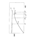
図1は、水量a1で最高効率η1を達成するように設計された、低比速度遠心ポンプ(特定低比速度遠心ポンプ)の水量−揚程曲線X1及び効率曲線Y1を示す。低比速度遠心ポンプにあっては、ポンプの最高効率η1に極力近い水量で運転することが、騒音や振動などを低減させてポンプを機械的に安定させる上で好ましい。このため、最高効率点の水量a1の、例えば80%を最低水量a1’(=a1×0.8)に、例えば110%を最高水量a1”(=a1×1.1)にそれぞれ設定し、この水量範囲(a1’〜a1”)をポンプの運転水量範囲A1と規定することが広く行われている。 FIG. 1 shows a water volume-head curve X1 and an efficiency curve Y1 of a low specific speed centrifugal pump (specific low specific speed centrifugal pump) designed to achieve a maximum efficiency η1 with a water volume a1. In a low specific speed centrifugal pump, it is preferable to operate with a water amount as close as possible to the maximum efficiency η1 of the pump in order to reduce noise and vibration and to stabilize the pump mechanically. For this reason, for example, 80% of the maximum efficiency point water amount a1 is set to the minimum water amount a1 ′ (= a1 × 0.8), and for example, 110% is set to the maximum water amount a1 ″ (= a1 × 1.1). It is widely performed that this water amount range (a1 ′ to a1 ″) is defined as a pump operation water amount range A1.
このため、特定低比速度遠心ポンプの運転水量範囲A1から外れた、例えば図1に示す水量a2での運転の要請に該特定低比速度遠心ポンプを使用して応えようとすると、この水量a2における特定低比速度遠心ポンプの効率η2は、最高効率点から大きく外れ最高効率η1からかなり低くなり、騒音や振動などが発生する虞がある。このため、このような場合には、図2に破線で示すような水量−揚程曲線X2及び効率曲線Y2を有し、水量a2で最高効率を達成するか、またはこの水量a2がポンプの運転水量範囲A2内にあるようにした低比速度遠心ポンプを特定低比速度遠心ポンプとは別に用意して使用することが広く行われている。 For this reason, if the specific low specific speed centrifugal pump is used to respond to the request for operation at the water amount a2 shown in FIG. 1, for example, out of the operating water amount range A1 of the specific low specific speed centrifugal pump, the water amount a2 The efficiency η2 of the specific low specific speed centrifugal pump in FIG. 3 is greatly deviated from the maximum efficiency point and considerably lower than the maximum efficiency η1, and noise and vibration may occur. Therefore, in such a case, the water amount-head curve X2 and the efficiency curve Y2 as shown by the broken line in FIG. 2 are provided, and the maximum efficiency is achieved with the water amount a2, or this water amount a2 is the operating water amount of the pump. A low specific speed centrifugal pump that is in the range A2 is widely used separately from a specific low specific speed centrifugal pump.
出願人は、小水量側に最高効率点を持つ低比速度遠心ポンプに使用される羽根車として、互いに隣接する一方の羽根(主翼)の裏面と他方の羽根(主翼)の表面との間に、羽根車の外径より内側に位置して一方の羽根の裏面から他方の羽根の表面に向けて延びる仕切翼を設けた羽根車を提案している(特許文献1参照)。また、第1の通液路を有する羽根車本体の外周部に嵌合する円筒状の補助リングを備え、補助リングに該補助リングの内周部から外周部まで延びる第2の通液路を設けた羽根車を提案している(特許文献2参照)。 As the impeller used for the low specific speed centrifugal pump having the highest efficiency point on the small water volume side, the applicant applies between the back surface of one blade (main wing) adjacent to each other and the surface of the other blade (main wing). An impeller provided with partitioning blades located inside the outer diameter of the impeller and extending from the back surface of one blade toward the surface of the other blade has been proposed (see Patent Document 1). In addition, a cylindrical auxiliary ring fitted to the outer peripheral portion of the impeller body having the first liquid passage is provided, and the second liquid passage extending from the inner peripheral portion to the outer peripheral portion of the auxiliary ring is provided in the auxiliary ring. The provided impeller is proposed (refer patent document 2).
しかしながら、客先の種々様々な要請に応えるため、異なる性能を満足する遠心ポンプをその都度、設計して製作すると、設計費用、製作コスト及び材料費等が嵩み、遠心ポンプそのもののコストアップに繋がってしまう。しかも、このように材料が費やされると、限りある資源の無駄使いにもなる。特許文献1,2に記載の羽根車にあっても、ポンプ性能に合わせた羽根車自体の加工が必要で、一つの性能を有する遠心ポンプに対して、一つの羽根車が必要となる。このため、一つの羽根車で複数の性能を任意に選択することはできない。 However, in order to respond to various requests from customers, designing and manufacturing a centrifugal pump that satisfies different performance each time increases design costs, manufacturing costs, material costs, etc., and increases the cost of the centrifugal pump itself. It will be connected. In addition, if the material is consumed in this way, it becomes a waste of limited resources. Even in the impellers described in Patent Documents 1 and 2, it is necessary to process the impeller itself according to the pump performance, and one impeller is required for a centrifugal pump having one performance. For this reason, a plurality of performances cannot be arbitrarily selected with one impeller.
このため、出願人は、図3及び図4に示すように、一つのケーシングと一つの羽根車の組合せによって、最高効率の水量を任意に変更できるようにした遠心ポンプを提案している(特願2010−231069号(出願日2010年10月14日))。この遠心ポンプは、吸込口10aと吐出口10bとを有するケーシング10と、ケーシング10の内部に回転自在に収容される羽根車12と、内部に羽根車12を収容したケーシング10の開口部を密閉するケーシングカバー14とを有している。羽根車12は、モータの回転に伴って回転する回転軸16の端部に連結されている。更に、この遠心ポンプは、羽根車側とケーシング側を貫通する複数の通路18a,18b,18c,18dを有するガイドプレート18を備えており、このガイドプレート18は、複数の通路内の一つの通路(例えば通路18a)のみが吐出口10bに連通し、他の通路(例えば通路18b,18c,18d)は羽根車側で仕切り板20によって閉止されるように、ケーシング10内に羽根車12と同心円状に配置される。これにより、複数の通路18a〜18d内の任意の一つの通路を吐出口10bに連通させ、他の通路を仕切り板20で閉止させることで、最高効率の水量を任意に変更した遠心ポンプを構成できる。
For this reason, the applicant has proposed a centrifugal pump in which the maximum amount of water can be arbitrarily changed by a combination of one casing and one impeller as shown in FIGS. Application No. 2010-231069 (filing date October 14, 2010)). This centrifugal pump hermetically seals a
しかしながら、出願人が提案した上記遠心ポンプは、所望の効果を奏するものの、複数の通路18a〜18d内の任意の一つの通路を吐出口10bに連通させ、他の通路を閉止させた状態で羽根車12を回転させてポンプを駆動すると、羽根車12に常に一方向の力が作用して左右のバランスが悪くなり、ポンプの安定した運転を行うためには、例えば回転軸や該回転軸を支持する軸受として、剛性の高いものを使用する必要があり、ポンプの大型化やコストアップに繋がってしまうことが判った。
However, the centrifugal pump applicant proposed, although achieves the desired effect, communicates any one passageway in the plurality of
本発明は上記事情に鑑みて為されたもので、一つのケーシングと一つの羽根車の組合せによって、最高効率の水量を任意に変更して、好ましい運転水量範囲を任意に選択しつつ構成でき、しかも羽根車をバランスよく回転させて安定した運転ができるようにした遠心ポンプを提供することを目的とする。 The present invention was made in view of the above circumstances, and by combining a single casing and a single impeller, the maximum amount of water can be arbitrarily changed, and a preferred operating water volume range can be arbitrarily selected and configured. And it aims at providing the centrifugal pump which rotated the impeller with sufficient balance and was able to perform the stable driving | operation.
請求項1に記載の発明は、回転軸に連結されて回転する羽根車と、吐出口を有し内部に前記羽根車を収容するケーシングと、前記ケーシングの開口部を密閉するケーシングカバーと、所定角度回転させた時に互いに略一致する位置に位置して羽根車側とケーシング側を貫通する一組の通路を複数組有し、前記ケーシングとの間に前記吐出口に連通する案内通路が形成されるように、前記ケーシング内に前記羽根車と同心円状に配置されるガイドプレートと、前記複数組の通路の内の一組の通路を残して他の通路を羽根車側で閉止する閉止部材とを有することを特徴とする遠心ポンプである。 The invention according to claim 1 is an impeller that is connected to a rotating shaft and rotates, a casing that has a discharge port and accommodates the impeller therein, a casing cover that seals an opening of the casing, A plurality of a set of passages that pass through the impeller side and the casing side are located at positions that substantially coincide with each other when rotated by an angle, and a guide passage that communicates with the discharge port is formed between the casing and the casing. A guide plate disposed concentrically with the impeller in the casing, and a closing member that closes the other passage on the impeller side while leaving one set of the plurality of passages. It is a centrifugal pump characterized by having.
これにより、例えば、ガイドプレートの所定角度回転させた時に略一致する位置(回転軸の軸心を中心にガイドプレートを180°回転させた時に略一致する位置(略点対称位置)やガイドプレートを120°回転させた時に略一致する位置等)に位置する一組の通路を2組有する時に、ガイドプレートの一方の一組の通路が案内通路を通してケーシングの吐出口に連通し、他方の一組の通路が閉止部材で閉止するようにして第1遠心ポンプを構成し、ガイドプレートの他方の一組の通路が案内通路を通してケーシングの吐出口に連通し、一方の一組の通路が閉止部材で閉止するようにして、前記第1遠心ポンプと異なる性能を有する第2遠心ポンプを構成することができる。この第1遠心ポンプ及び第2遠心ポンプにおいて、羽根車を回転させてポンプを駆動すると、ガイドプレートの所定角度回転させた時に略一致する位置に位置する一組の通路を通って流体が案内通路内に流入し吐出口から吐出されるため、羽根車に複数方向の力がより均等に作用し、これらの力が互いに相殺しあって左右のバランスが良くなり、羽根車をバランス良く回転させて、安定した運転を行うことができる。 Thus, for example, a position that substantially coincides when the guide plate is rotated by a predetermined angle (a position that substantially coincides when the guide plate is rotated 180 ° about the axis of the rotation shaft (substantially point symmetrical position) or a guide plate When there are two sets of passages positioned at substantially the same position when rotated by 120 °, one set of passages of the guide plate communicates with the discharge port of the casing through the guide passage, and the other set of passages. The first centrifugal pump is configured so that the passages of the guide plate are closed by the closing member, the other set of passages of the guide plate communicate with the discharge port of the casing through the guide passage, and the one set of passages is the closing member. A second centrifugal pump having a performance different from that of the first centrifugal pump can be configured so as to be closed. In the first centrifugal pump and the second centrifugal pump, when the impeller is rotated to drive the pump, the fluid is guided through a pair of passages located at substantially the same positions when the guide plate is rotated by a predetermined angle. Since it flows into the interior and is discharged from the discharge port, force in multiple directions acts on the impeller more evenly, and these forces cancel each other out, improving the balance between the left and right, and rotating the impeller in a balanced manner Stable operation can be performed.
請求項2に記載の発明は、前記ガイドプレートは、周方向に回転可能に前記ケーシング内に配置されて該ケーシングまたは前記ケーシングカバーに固定されることを特徴とする請求項1に記載の遠心ポンプである。 The invention according to claim 2 is characterized in that the guide plate is disposed in the casing so as to be rotatable in the circumferential direction and is fixed to the casing or the casing cover. It is.
これにより、ガイドプレートに設けた複数組の通路の内の一組の通路を残して他の通路が閉止部材で閉止されるようにガイドプレートを配置してケーシングまたはケーシングカバーに固定する時、ガイドプレートを周方向に回転させることで、ガイドプレートのケーシングまたはケーシングカバーに対する配置を容易に調整することができる。 Accordingly, when the guide plate is arranged and fixed to the casing or the casing cover so that the other passage is closed by the closing member while leaving one set of the plurality of sets of passages provided in the guide plate, the guide By rotating the plate in the circumferential direction, the arrangement of the guide plate with respect to the casing or the casing cover can be easily adjusted.
請求項3に記載の発明は、前記ガイドプレートの前記一組の通路を構成する各通路は、少なくとも一部の通路が異なる断面積を有していることを特徴とする請求項1または2記載の遠心ポンプである。 According to a third aspect of the present invention, at least some of the passages constituting the set of passages of the guide plate have different cross-sectional areas. This is a centrifugal pump.
ガイドプレートの一組の通路を構成する各通路は、全て略同じ断面積を有する方が羽根車をバランスよく回転させて安定した運転を行う上で好ましいが、必ずしも全て略同じ断面積を有している必要はない。 Each of the passages constituting a pair of passages of the guide plate preferably has substantially the same cross-sectional area, although it is preferable for stable operation by rotating the impeller in a balanced manner. You don't have to.
請求項4に記載の発明は、前記閉止部材は、前記ガイドプレートの羽根車側に内接した円弧状の仕切り板で構成され、該仕切り板は、前記ケーシングカバーと一体成形されていることを特徴とする請求項1乃至3のいずれかに記載の遠心ポンプである。 According to a fourth aspect of the present invention, the closing member is configured by an arc-shaped partition plate inscribed on the impeller side of the guide plate, and the partition plate is integrally formed with the casing cover. A centrifugal pump according to any one of claims 1 to 3, wherein
これにより、例えばガイドプレートをケーシングに固定した時、ケーシングとケーシングカバーとを相対的に回転させることで、ガイドプレートと仕切り板との相対位置を変更することができ、しかも、ケーシングカバーと仕切り板の取付けが容易となる。 Thereby, for example, when the guide plate is fixed to the casing, the relative position between the guide plate and the partition plate can be changed by relatively rotating the casing and the casing cover, and the casing cover and the partition plate can be changed. Is easy to install.
請求項5に記載の発明は、前記仕切り板は、前記羽根車の外周端面との間にボリュートとなる流路が形成されるように該流路内の流体の流れ方向に沿って厚さが減少する形状に形成されていることを特徴とする請求項4に記載の遠心ポンプである。
これにより、羽根車の外周端面と仕切り板との間に形成されるボリュートとなる流路に沿って流体がよりスムーズに流れるようにすることができる。
According to a fifth aspect of the present invention, the partition plate has a thickness along the fluid flow direction in the flow path so that a flow path serving as a volute is formed between the partition plate and the outer peripheral end surface of the impeller. The centrifugal pump according to claim 4, wherein the centrifugal pump is formed in a decreasing shape.
Thereby, a fluid can flow more smoothly along the flow path used as the volute formed between the outer peripheral end surface of an impeller and a partition plate.
請求項6に記載の発明は、前記案内通路は、前記ガイドプレートに設けられたフランジ部と前記ケーシングカバーで挟まれた領域に形成されることを特徴とする請求項1乃至5のいずれかに記載の遠心ポンプである。 The invention according to claim 6 is characterized in that the guide passage is formed in a region sandwiched between a flange portion provided in the guide plate and the casing cover. The described centrifugal pump.
請求項7に記載の発明は、前記案内通路は、前記ケーシングの前記ガイドプレートの外周端面との対向面に設けられた凹溝内に形成されることを特徴とする請求項1乃至5のいずれかに記載の遠心ポンプである。 According to a seventh aspect of the present invention, in any one of the first to fifth aspects, the guide passage is formed in a concave groove provided on a surface of the casing facing the outer peripheral end surface of the guide plate. It is a centrifugal pump as described above.
請求項8に記載の発明は、前記案内通路は、該案内通路内を流れる流体の流れ方向に沿って流路断面積が徐々に増大するボリュート形状を有することを特徴とする請求項6または7記載の遠心ポンプである。
これにより、ケーシングとガイドプレートとの間にボリュート形状に形成される案内通路に沿って流体がよりスムーズに流れるようにすることができる。
The invention according to claim 8 is characterized in that the guide passage has a volute shape in which the cross-sectional area of the flow path gradually increases along the flow direction of the fluid flowing in the guide passage. The described centrifugal pump.
Thereby, the fluid can flow more smoothly along the guide passage formed in a volute shape between the casing and the guide plate.
請求項9に記載の発明は、前記案内通路の前記吐出口近傍には、前記案内通路内を流れて吐出口から吐出される流体が該案内通路内に流入するのを防止する流れ止めが配置されていることを特徴とする請求項6または7記載の遠心ポンプである。
これにより、案内通路に沿って流れる流体を流れ止めで堰き止めて、案内通路に沿って流れてきた流体の全てを吐出口から順次吐出すことができる。
According to the ninth aspect of the present invention, a flow stop is disposed in the vicinity of the discharge port of the guide passage to prevent fluid flowing through the guide passage and discharged from the discharge port from flowing into the guide passage. The centrifugal pump according to claim 6 or 7, wherein the centrifugal pump is provided.
As a result, the fluid flowing along the guide passage is blocked by the flow stopper, and all of the fluid flowing along the guide passage can be sequentially discharged from the discharge port.
本発明の遠心ポンプによれば、一つのケーシングと一つの羽根車の組合せによって、最高効率の水量を任意に変更して、好ましい運転水量範囲を任意に選択しつつ遠心ポンプを構成することができる。しかも、このようにして構成された遠心ポンプは、羽根車を回転させてポンプを駆動させたとき、羽根車に複数方向の力がより均等に作用し、これらの力が互いに相殺しあって左右のバランスが良くなり、羽根車をバランス良く回転させて安定した運転を行うことができる。 According to the centrifugal pump of the present invention, the centrifugal pump can be configured while arbitrarily selecting a preferable operating water amount range by arbitrarily changing the maximum amount of water by combining one casing and one impeller. . In addition, when the centrifugal pump configured in this manner rotates the impeller and drives the pump, forces in a plurality of directions are more evenly applied to the impeller, and these forces cancel each other, and the left and right The balance is improved, and the impeller can be rotated in a well-balanced manner to perform stable operation.
これにより、客先の使用する水量ごとに遠心ポンプを設計し製作する必要をなくして、材料等の無駄をなくし、遠心ポンプのコストダウンを図るとともに、貴重な地球資源の無駄使いを無くして、省エネルギーに繋げることができる。特に、羽根車をバランス良く回転させて安定したポンプの運転を行うことで、例えば回転軸や該回転軸を支承する軸受として、剛性の低いものを使用することができ、これによって、ポンプを小型化して、製作コスト及び材料費の更なる削減を図ることができる。 This eliminates the need to design and manufacture centrifugal pumps for each amount of water used by customers, eliminates waste of materials, etc., reduces cost of centrifugal pumps, and eliminates wasteful use of valuable earth resources. It can lead to energy saving. In particular, by rotating the impeller in a well-balanced manner and performing a stable pump operation, for example, a rotating shaft and a bearing that supports the rotating shaft can be used with a low rigidity, thereby reducing the size of the pump. Therefore, the manufacturing cost and material cost can be further reduced.
しかも、一般の渦巻きポンプの構造を採用した小水量で高揚程の遠心ポンプは、出口通路の面積が一般に小さく、鋳造によってケーシングを得ようとすると、ケーシング内に通路を確実に成型できない場合があるが、本発明の遠心ポンプに使用される、ポンプ性能を決める通路が設けられているガイドプレートは、通路が開口しているので、鋳造によって比較的容易に成型することができる。 In addition, a centrifugal pump with a small amount of water and a high head that employs a general centrifugal pump structure generally has a small exit passage area, and when trying to obtain a casing by casting, the passage may not be reliably molded in the casing. However, since the guide plate used in the centrifugal pump of the present invention, which is provided with a passage that determines pump performance, has an open passage, it can be molded relatively easily by casting.
以下、本発明の実施形態を図5乃至図9を参照して説明する。なお、以下の各例において、同一または相当する部材には同一符号を付して重複した説明を省略する。 Hereinafter, embodiments of the present invention will be described with reference to FIGS. In the following examples, the same or corresponding members are denoted by the same reference numerals, and redundant description is omitted.
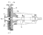
図5は、本発明の実施形態の遠心ポンプの縦断正面図で、図6は、図5のB−B線断面図である。図5及び図6に示すように、遠心ポンプは、吸込口30aと吐出口30bとを有するケーシング30と、ケーシング30の内部に回転自在に収容される羽根車32と、内部に羽根車32を収容したケーシング30の開口部を密閉するケーシングカバー34とを有している。ケーシングカバー34は、ボルト36を介してケーシング30に固定されている。
FIG. 5 is a longitudinal front view of the centrifugal pump according to the embodiment of the present invention, and FIG. 6 is a sectional view taken along line BB of FIG. As shown in FIGS. 5 and 6, the centrifugal pump includes a
羽根車32は、ケーシングカバー34に連結された軸受胴体40の内部に組込まれた軸受42,44によって回転自在に支承された回転軸46のケーシング30側の端部に固定されている。回転軸46の他端は、軸受胴体40から外部に延出して、図示しないモータに連結される。これにより、モータの駆動に伴って、羽根車32は回転軸46と一体に回転する。
The
羽根車32は、この例では、円板状の主板(ハブ)50の表面に、直線状に延びる複数の羽根52を放射状に配置して構成されている。羽根車の形状は、この構成に限定されず、用途に応じて、クローズ型、オープン型、セミオープン型など種々の羽根車が適用できる。
In this example, the
ケーシング30の羽根車32側の内面には、羽根車32の周囲を囲繞するリング状の突条部54aと該突条部54aより外方に延出するフランジ部54bを有する略円板状のガイドプレート54が羽根車32と同心円状に周方向に回転可能に配置され、ガイドプレート54の突条部54aの突出端面がケーシングカバー34に、フランジ部54bの外周端面がケーシング30にそれぞれ当接した状態で、ボルト56を介してケーシング30に固定されている。これにより、ケーシング30とケーシングカバー34で挟まれた領域内に位置して、羽根車32の外周端面とガイドプレート54の突条部54aとの間に円周状に連続した流路58が形成され、ガイドプレート54の突条部54aとケーシング30との間に円周状に連続した案内通路60が形成されている。
The inner surface of the
この例では、ガイドプレート54をケーシング30にボルト56で固定しているが、ガイドプレート54をケーシングカバー34にボルト等で固定するようにしてもよい。
In this example, the
ガイドプレート54には、流路58の接線方向に延びて羽根車32側とケーシング30側とを貫通し、流路58と案内通路60を繋ぐ、この例では、第1の一対の通路62a,62bと第2の一対の通路64a,64bのポンプ性能を決める2対の通路が備えられ、これらの一対の通路の内の一方の一対の通路のみが通路として使用され、他方の一対の通路は閉塞されるようになっている。第1の一対の通路62a,62bは、ガイドプレート54の略点対称位置に、つまり回転軸46の軸心Oと一致するガイドプレート54の中心を中心として、ガイドプレート54を略180°回転した位置に設けられ、第2の一対の通路64a,64bも同様に、ガイドプレート54の略点対称位置に、つまり回転軸46の軸心Oと一致するガイドプレート54の中心を中心として、ガイドプレート54を略180°回転した位置に設けられている。
The
これらの通路62a,62b、64a,64bは、ケーシングカバー34側に開口しており、第1の一対の通路62a,62bを互いに結ぶ線と第2の一対の通路64a,64bを互いに結ぶ線の成す角は、90°に設定されている。なお、ガイドプレートに設けられる通路の数は、複数対であればよい。
These
このような形状のガイドプレート54は、ポンプ性能を決める所定形状の2対の通路62a,62b、64a,64bが形成されているものの、これらの通路62a,62b、64a,64bは、ケーシングカバー34側に開口しているので、鋳造によって比較的容易に成型することができる。
The
図6に示すように、例えば第1の一対の通路62a,62bを、流路58と案内通路60を繋ぐ通路として使用する時、第2の一対の通路64a,64bは、通路として使用されない。このため、通路として使用されない第2の一対の通路64a,64bを羽根車32側で閉止する位置に、この第2の一対の通路64a,64bをそれぞれ閉止する閉止部材を構成する一対の仕切り板70が設けられている。
As shown in FIG. 6, for example, when the first pair of
この例では、各仕切り板(閉止部材)70は、ガイドプレート54の突条部54aの内周面に内接する円弧状の板体で構成されてケーシングカバー34に一体に設けられている。これにより、例えば図6に示す状態で、ケーシング30に固定したガイドプレート54を、ケーシングカバー34に対して時計周りに90°回転させることで、第2の一対の通路64a,64bの仕切り板70による閉止が解かれて、第2の一対の通路64a,64bが、流路58と案内通路60を繋ぐ通路として使用され、第1の一対の通路62a,62bは、仕切り板70で閉止されるようになっている。
In this example, each partition plate (closing member) 70 is formed of an arc-shaped plate that is inscribed in the inner peripheral surface of the
更にこの例では、各仕切り板70として、羽根車32の外周端面と仕切り板70との間に形成される流路58が水の流れる方向に間口が広がるボリュートを形成するように、流体の流れ方向に向けて厚さが徐々に薄くなるようにしたものが使用されている。即ち、仕切り板70の流体の流れ方向の上流側に位置する端部の厚さt1は、下流側に位置する端部の厚さt2よりも厚く(t1>t2)なっている。
Furthermore, in this example, as the
第1の一対の通路62a,62b及び第2の一対の64a,64bの通路部分の大きさは、第1の一対の通路62a,62bと第2の一対の64a,64bで異なるポンプ性能を決めることができるように設定されている。つまり、第1の一対の通路62a,62bの通路部分の大きさは、第1の一対の通路62a,62bを通路として使用し、第2の一対の通路64a,64bを仕切り板70で閉止して第1遠心ポンプを構成した場合、この第1遠心ポンプの水量−揚程曲線及び効率曲線が、例えば図1に示す水量−揚程曲線X1及び効率曲線Y1に一致して、水量a1で最大効率点となるように設定されている。
The sizes of the passage portions of the first pair of
第2の一対の通路64a,64bの通路部分の大きさは、第2の一対の通路64a,64bを通路として使用し、第1の一対の通路62a,62bを仕切り板70で閉止して第2遠心ポンプを構成した場合、この第2遠心ポンプの水量−揚程曲線及び効率曲線が、例えば図2に示す水量−揚程曲線X2及び効率曲線Y2に一致して、水量a2で最大効率点となるように設定されている。
The size of the passage portion of the second pair of
なお、この例では、第1の一対の通路を構成する各通路62a,62bとして、略同一形状(断面積)のものを使用している。第2の一対の通路を構成する各通路64a,64bにあっても同様に、略同一形状のものを使用している。このように、一対の通路を構成する各通路として、略同一形状のものを使用する方が羽根車32をバランスよく回転させて安定した運転を行う上で好ましい。
In this example, the
この例では、ガイドプレート54に設けた2対の通路62a,62b、64a,64bの内の一方の一対の通路を、流路58と案内通路60を繋ぐ通路として使用し、他方の一対の通路を仕切り板70で閉止させて遠心ポンプを構成することで、異なる水量−揚程曲線及び性能曲線を有する2種類の遠心ポンプが得られる。これによって、遠心ポンプを新たに設計して、新たな遠心ポンプを製作することなく、一つのケーシング30と一つの羽根車32を使用し、単にガイドプレート54と仕切り板70の相対位置を変更することで、異なる水量−揚程曲線及び性能曲線を有する遠心ポンプを構成することができる。
In this example, one pair of
この例では、2対の通路を備え、一対の通路を閉止することで、2つの異なる水量−揚程曲線及び性能曲線を有する遠心ポンプを構成することができるようにしているが、例えば3対の通路を備え、3対の通路の内、2対の通路を閉止することで、3つの異なる水量−揚程曲線及び性能曲線を有する遠心ポンプを構成するようにしても良い。 In this example, two pairs of passages are provided, and by closing the pair of passages, a centrifugal pump having two different water volume-lift curves and performance curves can be configured. A centrifugal pump having three different water volume-lift curves and performance curves may be configured by providing a passage and closing two pairs of the three pairs of passages.
そして、例えば図6に示すように、第1の一対の通路62a,62bを、流路58と案内通路60を繋ぐ通路として使用し、第2の一対の通路64a,64bを仕切り板70で閉止して第1遠心ポンプを構成し、羽根車32を回転させてポンプを駆動する場合、羽根車32の回転に伴って、吸込口30aから吸込まれて昇圧された流体は、流路58から、ガイドプレート54の互いに略点対称位置に設けられた第1の一対の通路62a,62bを通って、案内通路60内に流入し、吐出口30bから吐出される。これにより、羽根車32に回転軸46の軸心Oを中心とした略点対称位置の2方向の力が作用し、これらの力が互いに相殺しあって左右のバランスが良くなり、羽根車32をバランス良く回転させて、安定した運転を行うことができる。
For example, as shown in FIG. 6, the first pair of
このことは、第2の一対の通路64a,64bを流路58と案内通路60を繋ぐ通路として使用し、第1の一対の通路62a,62bを仕切り板70で閉止して構成した第2遠心ポンプにあっても同様である。
This is because the second pair of
このように、羽根車32をバランス良く回転させて安定したポンプの運転を行うことで、例えば回転軸46や該回転軸46を支承する軸受42,44として、剛性の低いものを使用することができ、これによって、ポンプを小型化して、製作コスト及び材料費の更なる削減を図ることができる。
Thus, by rotating the
なお、上記の例では、第1の一対の通路62a,62bと第2の一対の通路64a,64bを、ガイドプレート54の略点対称位置にそれぞれ設け、ケーシング30に固定したガイドプレート54を、ケーシングカバー34に対して時計周りに90°回転させることで、一方の一対の通路62a,62bまたは64a,64bを選択的に通路として使用するようにしているが、ガイドプレートの所定角度回転させた時に略一致する位置、例えばガイドプレートを120°回転させた時に一致する位置に第1の一組(3個)の通路と第2の一組(3個)の通路をそれぞれ設け、ケーシングに固定したガイドプレートを、ケーシングカバーに対して時計周りに60°回転させることで、一方の一組の通路を選択的に通路として使用する(他方の一組の通路を仕切り板で閉止)ようにしてもよい。このことは、以下の各例にあっても同様である。
In the above example, the first pair of
これによっても、複数方向の力を羽根車により均等に作用させ、これらの力を互いに相殺させて左右のバランスを良くし、羽根車をバランス良く回転させて、安定した運転を行うことができる。 This also makes it possible to perform a stable operation by causing forces in a plurality of directions to be applied evenly by the impeller, offsetting these forces to improve the left and right balance, and rotating the impeller in a balanced manner.
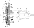
図7は、本発明の他の実施形態の遠心ポンプを示す。図7は、通路64aを仕切り板70で閉止した状態を示している。この例の図5及び図6に示す例と異なる点は、図5及び図6に示す例は、ガイドプレート54にフランジ部54bを設けて、このフランジ部54bとケーシングカバー34で挟まれた領域に案内通路60を形成しているのに対し、この例は、ガイドプレート54にフランジ部を設けることなく、ケーシング30のガイドプレート54の外周端面との対向面に凹溝30cを設け、この凹溝30cの開口部をガイドプレート54の突条部54aで塞ぐことで、凹溝30cの内部に案内通路60を形成している点にある。この例にあっては、ケーシング30に設けられる凹溝30cの形状に沿って案内通路60が形成される。
FIG. 7 shows a centrifugal pump according to another embodiment of the present invention. FIG. 7 shows a state where the
図8は、本発明の更に他の実施形態の遠心ポンプを示す。この例の図5及び図6に示す例と異なる点は、リング状に延びる案内通路60のケーシング30の吐出口30bの近傍に、案内通路60内を流れて吐出口30bから吐出される流体が該案内通路60内に流入するのを防止する流れ止め72を配置した点にある。これにより、案内通路60に沿って流れる流体の全量をケーシング30の吐出口30bから順次吐出すことができる。この流れ止め72の吐出口30bに連続する面72aは、該面72aに沿って流体がスムーズに流れるよう、流体の流れに沿った形状に形成されている。
FIG. 8 shows a centrifugal pump according to still another embodiment of the present invention. 5 and 6 of this example is different from the example shown in FIGS. 5 and 6 in that the fluid that flows in the
更に、この例にあっては、第1の一対の通路を構成する各通路62a,62bとして、異なる形状(断面積)のものを使用している。第2の一対の通路を構成する各通路64a,64bにあっても同様に、異なる形状のものを使用している。前述のように、一対の通路を構成する各通路として、略同一形状のものを使用することが理想であるが、必ずしも略同一形状である必要はない。
Further, in this example, the
図9は、本発明の更に他の実施形態の遠心ポンプを示す。この例の図5及び図6に示す例と異なる点は、ガイドプレート54の突条部54aの厚さが流体の流れ方向に沿って徐々に小さくなって、ガイドプレート54の突条部54aとケーシング30との間に、流路断面積が流体の流れ方向に沿って徐々に増大するボリュート形状の案内通路60が形成されるようにしている点にある。
FIG. 9 shows a centrifugal pump according to still another embodiment of the present invention. 5 and FIG. 6 of this example is different from the example shown in FIGS. 5 and 6 in that the thickness of the
このように、ケーシング30とガイドプレート54の突条部54aとの間に形成される案内通路60を、流路断面積が流体の流れ方向に沿って徐々に増大するボリュート形状とすることによって、この案内通路60に沿って流体がよりスムーズに流れるようにすることができる。
Thus, by making the
なお、図8に示す例にあっては、ガイドプレート54のフランジ部54bとケーシングカバー34で挟まれた領域に形成した案内通路60の内部に流れ止め72を配置しているが、図7に示すように、ケーシング30に設けた凹溝30cで案内流路60を形成する場合には、凹溝30cの内部に流れ止めを配置するようにしても良い。また、図9に示す例にあっては、ガイドプレート54のフランジ部54bとケーシングカバー34で挟まれた領域にボリュート形状の案内通路60を形成しているが、図7に示すように、ケーシング30に設けた凹溝30cで案内流路60を形成する場合には、この案内通路を形成する凹溝30cの形状をボリュート形状としてもよい。
In the example shown in FIG. 8, the
これまで本発明の一実施形態について説明したが、本発明は上述の実施形態に限定されず、その技術的思想の範囲内において種々異なる形態にて実施されてよいことはいうまでもない。 Although one embodiment of the present invention has been described so far, it is needless to say that the present invention is not limited to the above-described embodiment, and may be implemented in various forms within the scope of the technical idea.
30 ケーシング
30a 吸込口
30b 吐出口
32 羽根車
34 ケーシングカバー
40 軸受胴体、
42,44 軸受
46 回転軸
50 主板
52 羽根
54 ガイドプレート
54a 突条部
54b フランジ部
58 流路
60 案内通路
62a,62b、64a,64b 通路
70 仕切り板
72 流れ止め
30
42, 44
Claims (9)
吐出口を有し内部に前記羽根車を収容するケーシングと、
前記ケーシングの開口部を密閉するケーシングカバーと、
所定角度回転させた時に略一致する位置に位置して羽根車側とケーシング側を貫通する一組の通路を複数組有し、前記ケーシングとの間に前記吐出口に連通する案内通路が形成されるように、前記ケーシング内に前記羽根車と同心円状に配置されるガイドプレートと、
前記複数組の通路の内の一組の通路を残して他の通路を羽根車側で閉止する閉止部材とを有することを特徴とする遠心ポンプ。 An impeller connected to a rotating shaft and rotating;
A casing having a discharge port and containing the impeller inside;
A casing cover for sealing the opening of the casing;
A plurality of sets of passages that pass through the impeller side and the casing side are located at substantially the same position when rotated by a predetermined angle, and a guide passage communicating with the discharge port is formed between the casing and the casing. A guide plate disposed concentrically with the impeller in the casing,
A centrifugal pump, comprising: a closing member that closes one of the plurality of sets of passages and closes the other passage on the impeller side.
Priority Applications (3)
| Application Number | Priority Date | Filing Date | Title |
|---|---|---|---|
| JP2011204377A JP5706792B2 (en) | 2011-09-20 | 2011-09-20 | Centrifugal pump |
| CN201210048735.2A CN103016350B (en) | 2011-09-20 | 2012-02-27 | Centrifugal pump |
| HK13108723.2A HK1181445A1 (en) | 2011-09-20 | 2013-07-25 | Centrifugal pump |
Applications Claiming Priority (1)
| Application Number | Priority Date | Filing Date | Title |
|---|---|---|---|
| JP2011204377A JP5706792B2 (en) | 2011-09-20 | 2011-09-20 | Centrifugal pump |
Publications (3)
| Publication Number | Publication Date |
|---|---|
| JP2013064383A JP2013064383A (en) | 2013-04-11 |
| JP2013064383A5 JP2013064383A5 (en) | 2014-05-29 |
| JP5706792B2 true JP5706792B2 (en) | 2015-04-22 |
Family
ID=47965322
Family Applications (1)
| Application Number | Title | Priority Date | Filing Date |
|---|---|---|---|
| JP2011204377A Expired - Fee Related JP5706792B2 (en) | 2011-09-20 | 2011-09-20 | Centrifugal pump |
Country Status (3)
| Country | Link |
|---|---|
| JP (1) | JP5706792B2 (en) |
| CN (1) | CN103016350B (en) |
| HK (1) | HK1181445A1 (en) |
Families Citing this family (2)
| Publication number | Priority date | Publication date | Assignee | Title |
|---|---|---|---|---|
| CA2871451C (en) * | 2012-04-27 | 2019-09-24 | Weir Minerals Australia, Ltd. | Centrifugal pump casing with offset discharge |
| JP6476951B2 (en) * | 2015-02-10 | 2019-03-06 | アイシン精機株式会社 | Centrifugal pump |
Family Cites Families (7)
| Publication number | Priority date | Publication date | Assignee | Title |
|---|---|---|---|---|
| JPH05187399A (en) * | 1992-01-13 | 1993-07-27 | Mitsubishi Heavy Ind Ltd | Flow rate variable pump |
| JP2002257084A (en) * | 2001-02-26 | 2002-09-11 | Ebara Corp | Centrifugal pump |
| JP2005023794A (en) * | 2003-06-30 | 2005-01-27 | Ebara Corp | Impeller |
| JP2007051592A (en) * | 2005-08-18 | 2007-03-01 | Ebara Corp | Impeller and pump |
| CN201606254U (en) * | 2009-11-30 | 2010-10-13 | 芜湖中能机械制造有限公司 | Centrifugal water pump |
| CN201802628U (en) * | 2010-09-13 | 2011-04-20 | 界首市东亚淀粉出品有限公司 | Water circulation system for centrifugal spraying |
| JP5481346B2 (en) * | 2010-10-14 | 2014-04-23 | 株式会社荏原製作所 | Centrifugal pump |
-
2011
- 2011-09-20 JP JP2011204377A patent/JP5706792B2/en not_active Expired - Fee Related
-
2012
- 2012-02-27 CN CN201210048735.2A patent/CN103016350B/en not_active Expired - Fee Related
-
2013
- 2013-07-25 HK HK13108723.2A patent/HK1181445A1/en not_active IP Right Cessation
Also Published As
| Publication number | Publication date |
|---|---|
| CN103016350B (en) | 2016-05-04 |
| CN103016350A (en) | 2013-04-03 |
| HK1181445A1 (en) | 2013-11-08 |
| JP2013064383A (en) | 2013-04-11 |
Similar Documents
| Publication | Publication Date | Title |
|---|---|---|
| US10495102B2 (en) | Impeller and pump using the impeller | |
| JP5456491B2 (en) | Double suction pump | |
| WO2017138199A1 (en) | Centrifugal compressor | |
| WO2012033192A1 (en) | Sealing structure and centrifugal compressor | |
| JP2016031064A (en) | Multiple stage pump | |
| WO2014112473A1 (en) | Centrifugal pump | |
| JP5706792B2 (en) | Centrifugal pump | |
| JP6627175B2 (en) | Impeller and centrifugal compressor | |
| JP2016109087A (en) | Water power machine | |
| JP5481346B2 (en) | Centrifugal pump | |
| WO2016121046A1 (en) | Centrifugal-compressor casing and centrifugal compressor | |
| JP6775379B2 (en) | Impeller and rotating machine | |
| JP5568383B2 (en) | Water pump | |
| JP2011140916A (en) | Double suction pump | |
| JP6667323B2 (en) | Centrifugal rotating machine | |
| JP7461715B2 (en) | Compressor | |
| JP4655603B2 (en) | Centrifugal compressor | |
| JP6740070B2 (en) | Fluid machinery | |
| JP5748505B2 (en) | Rotating machine | |
| JP5766461B2 (en) | Pump device | |
| JP2013064383A5 (en) | ||
| JP6042129B2 (en) | Wear ring and centrifugal pump device using the same | |
| JP2012002153A (en) | Multi-stage pump | |
| JP5699274B2 (en) | pump | |
| JP2009228503A (en) | Fuel pump |
Legal Events
| Date | Code | Title | Description |
|---|---|---|---|
| A521 | Written amendment |
Free format text: JAPANESE INTERMEDIATE CODE: A523 Effective date: 20140408 |
|
| A621 | Written request for application examination |
Free format text: JAPANESE INTERMEDIATE CODE: A621 Effective date: 20140408 |
|
| A977 | Report on retrieval |
Free format text: JAPANESE INTERMEDIATE CODE: A971007 Effective date: 20150119 |
|
| TRDD | Decision of grant or rejection written | ||
| A01 | Written decision to grant a patent or to grant a registration (utility model) |
Free format text: JAPANESE INTERMEDIATE CODE: A01 Effective date: 20150203 |
|
| A61 | First payment of annual fees (during grant procedure) |
Free format text: JAPANESE INTERMEDIATE CODE: A61 Effective date: 20150227 |
|
| R150 | Certificate of patent or registration of utility model |
Ref document number: 5706792 Country of ref document: JP Free format text: JAPANESE INTERMEDIATE CODE: R150 |
|
| R250 | Receipt of annual fees |
Free format text: JAPANESE INTERMEDIATE CODE: R250 |
|
| R250 | Receipt of annual fees |
Free format text: JAPANESE INTERMEDIATE CODE: R250 |
|
| LAPS | Cancellation because of no payment of annual fees |