JP5704980B2 - Phased array antenna device - Google Patents
Phased array antenna device Download PDFInfo
- Publication number
- JP5704980B2 JP5704980B2 JP2011056540A JP2011056540A JP5704980B2 JP 5704980 B2 JP5704980 B2 JP 5704980B2 JP 2011056540 A JP2011056540 A JP 2011056540A JP 2011056540 A JP2011056540 A JP 2011056540A JP 5704980 B2 JP5704980 B2 JP 5704980B2
- Authority
- JP
- Japan
- Prior art keywords
- array antenna
- antenna
- aperture
- transmission
- opening
- Prior art date
- Legal status (The legal status is an assumption and is not a legal conclusion. Google has not performed a legal analysis and makes no representation as to the accuracy of the status listed.)
- Active
Links
- 230000005540 biological transmission Effects 0.000 claims description 122
- 238000004891 communication Methods 0.000 claims description 68
- 238000004364 calculation method Methods 0.000 claims description 41
- 230000005855 radiation Effects 0.000 claims description 11
- 230000035945 sensitivity Effects 0.000 claims description 8
- 238000001514 detection method Methods 0.000 claims description 7
- 230000015572 biosynthetic process Effects 0.000 claims description 4
- 238000000034 method Methods 0.000 description 12
- 238000010586 diagram Methods 0.000 description 6
- 230000004913 activation Effects 0.000 description 5
- 230000002457 bidirectional effect Effects 0.000 description 3
- 230000007812 deficiency Effects 0.000 description 3
- 230000008569 process Effects 0.000 description 3
- 230000008901 benefit Effects 0.000 description 2
- 230000005284 excitation Effects 0.000 description 2
- 230000010355 oscillation Effects 0.000 description 2
- 230000003321 amplification Effects 0.000 description 1
- 230000008859 change Effects 0.000 description 1
- 238000005516 engineering process Methods 0.000 description 1
- 230000007274 generation of a signal involved in cell-cell signaling Effects 0.000 description 1
- 238000004519 manufacturing process Methods 0.000 description 1
- 238000003199 nucleic acid amplification method Methods 0.000 description 1
- 238000004148 unit process Methods 0.000 description 1
Images


Description
本発明は、レーダ装置、ECM(Electronic Counter Measures)装置、通信機器など
の電波機器(電波装置とも称す)に用いるフェーズドアレーアンテナに関するものであって、特に、フェーズドアレーアンテナを複数の電波機器で共用するための技術に関するものである。
The present invention relates to a phased array antenna used in radio equipment (also referred to as radio equipment) such as radar equipment, ECM (Electronic Counter Measures) equipment, and communication equipment, and in particular, the phased array antenna is shared by a plurality of radio equipment. It is about the technology to do.
従来、レーダ装置、ECM装置、通信装置などは、個別に空中線を備えていた。
しかし、艦船や航空機などにおいて、空中線を搭載するプラットホームが狭い所に新たな電波機器を設置する場合、空中線間で電磁干渉が生じたり、また、プラットホームが狭い場合には物理的に空中線が配置できない等の問題があった。
これらの問題を解決するため、1つの空中線を複数の電波機器で共用する方法が考えられる。
例えば、下記の非特許文献1では、1つのアレーアンテナの開口を分割し、レーダ、ECM装置、通信装置等で共用する方法が示されている。
Conventionally, radar devices, ECM devices, communication devices, and the like have been individually provided with an antenna.
However, when a new radio wave device is installed in a place where the platform carrying the aerial is narrow, such as a ship or aircraft, electromagnetic interference occurs between the aerials, and if the platform is narrow, the aerial cannot be physically located. There was a problem such as.
In order to solve these problems, a method of sharing one antenna with a plurality of radio wave devices is conceivable.
For example, the following Non-Patent
非特許文献1に示されたアレイアンテナ装置の場合には、送信アレイにおいて、近接配置された複数のアンテナ素子を1つの群として複数の群に群分けし、各群のアンテナ素子は、複数の送信信号発生器とクロスポイントスイッチとからなる信号分配器を介して接続されている。
上記非特許文献1のアレイアンテナ装置では、送信信号発生器で生成した送信高周波信号を分配して任意の群のアンテナ素子に給電し、送信アレイアンテナの開口面を分割することにより、それぞれを複数の通信や電子戦、レーダなどに割り当てて、同時に使用可能な構成としている。
In the case of the array antenna device shown in Non-Patent
In the array antenna device of Non-Patent
非特許文献1に示す方法では、レーダ装置、ECM装置、通信装置などの電波機器(電波装置)に割り当てるアレーアンテナの開口分割の寸法を、所望の任意の寸法に設定できない。
何故ならば、通常のアレーアンテナでは、送信信号はアンテナの外部で生成され、アンテナ内部では送信信号を分配してモジュールに供給するだけなので、信号を分配する範囲はアンテナ製造時の配線に依存し、配線を切り替えるにしてもアンテナ製造時に作りつけた数通りにしか切り替えられないためである。
従って、非特許文献1に示す方法では、各電波装置により適した開口寸法とすることができないという問題があった。
In the method shown in Non-Patent
This is because, in a normal array antenna, the transmission signal is generated outside the antenna, and the transmission signal is only distributed and supplied to the module inside the antenna. Therefore, the range in which the signal is distributed depends on the wiring when the antenna is manufactured. This is because, even if the wiring is switched, it can be switched only in a number of ways created at the time of manufacturing the antenna.
Therefore, the method shown in Non-Patent
即ち、大開口面積を必要とする電波機器(電波装置)に対しては十分な開口面積を確保できずに性能が劣化し、また、小開口面積でよい電波機器に対しては開口面積が必要以上に大きくなり過剰な性能となったり、あるいは消費電力が過大となってしまうという問題
があった。
また、非特許文献1には、開口分割の寸法の決定法に関する記述も無く、完全に自由な寸法で分割可能なアレーアンテナを用いたとしても、厳密に最適な分割寸法を決定することができないという課題があった。
In other words, a sufficient opening area cannot be secured for a radio wave device (radio wave device) that requires a large opening area, and the performance deteriorates. Also, a radio wave device that requires a small opening area requires an opening area. There has been a problem that the size becomes larger and the performance becomes excessive, or the power consumption becomes excessive.
Further, Non-Patent
本発明はこれらの課題を解決するためのものであり、1つのアンテナの開口を分割して複数の電波機器(電波装置)で共用する場合において、各電波装置に必要十分な性能を与える開口の分割寸法を決定し、十分な性能を得ると共に、無駄な消費電力を無くすことができるフェーズドアレーアンテナ装置を得ることを目的とする。 The present invention is for solving these problems, and in the case where the opening of one antenna is divided and shared by a plurality of radio wave devices (radio wave devices), the opening of the aperture that gives each radio wave device a necessary and sufficient performance is provided. An object of the present invention is to obtain a phased array antenna apparatus capable of determining a division dimension, obtaining sufficient performance, and eliminating unnecessary power consumption.
本発明に係るフェーズドアレーアンテナ装置は、2次元配列された複数の送信モジュールで構成された送信アンテナと2次元配列された複数の受信モジュールで構成された受信アンテナとを有し、前記送信アンテナおよび前記受信アンテナの開口を分割することにより使用する複数の電波装置の機能を実現するフェーズドアレーアンテナ装置であって、
前記複数の電波装置のそれぞれが必要とする開口寸法を計算する開口寸法計算部と、
前記開口寸法計算部の計算結果に基づいて前記送信アンテナの開口を分割すると共に、分割された各開口のビーム形成やビーム走査の制御を行う送信アンテナ制御部と、
前記開口寸法計算部の計算結果に基づいて前記受信アンテナの開口を分割し、前記複数の電波装置から受信する複数の受信信号を前記複数の電波装置の各機能に対応して制御する受信アンテナ制御部を備え、
前記開口寸法計算部は、それぞれの電波装置が必要とする所要実効輻射電力を計算し、前記送信アンテナによる実効輻射電力が前記所要実効輻射電力以上となる前記開口寸法を、前記所要実効輻射電力、所要ビーム幅あるいはその両方を用いて計算する。
A phased array antenna apparatus according to the present invention includes a transmission antenna configured with a plurality of transmission modules arranged two-dimensionally and a reception antenna configured with a plurality of reception modules arranged two-dimensionally, A phased array antenna device that realizes the functions of a plurality of radio wave devices used by dividing the opening of the receiving antenna,
An aperture size calculation unit for calculating an aperture size required by each of the plurality of radio wave devices;
A transmission antenna control unit that divides the aperture of the transmission antenna based on the calculation result of the aperture size calculation unit, and controls beam formation and beam scanning of each of the divided apertures;
Receiving antenna control that divides the opening of the receiving antenna based on the calculation result of the opening size calculation unit and controls a plurality of received signals received from the plurality of radio wave devices corresponding to each function of the plurality of radio wave devices Part
The aperture size calculation unit calculates a required effective radiant power required by each radio wave device , and sets the aperture size at which the effective radiated power by the transmission antenna is equal to or greater than the required effective radiant power, the required effective radiant power, Calculate using the required beam width or both .
本発明のフェーズドアレーアンテナ装置によると、開口寸法計算部は、それぞれの電波装置が必要とする所要実効輻射電力を計算し、前記送信アンテナによる実効輻射電力が前記所要実効輻射電力以上となる前記開口寸法を、前記所要実効輻射電力、所要ビーム幅あるいはその両方を用いて計算するので、共用して使用する各電波装置に必要十分な性能を与える最適な開口の分割寸法(即ち、最適な分割開口面積)を決定し、各電波装置の所要性能を過不足なく実現することができると共に、無駄な消費電力を無くすことができるフェーズドアレーアンテナ装置を実現できる。 According to the phased array antenna device of the present invention, the aperture size calculation unit calculates the required effective radiant power required by each radio wave device, and the effective radiant power by the transmitting antenna is equal to or greater than the required effective radiant power. Since the dimensions are calculated using the required effective radiant power, the required beam width, or both, the optimal aperture split dimensions (that is, the optimal split aperture) that provide the necessary and sufficient performance for each radio wave device used in common. The phased array antenna apparatus can be realized that can achieve the required performance of each radio wave device without excess or deficiency and can eliminate wasteful power consumption.
以下、図面にも基づいて、本発明の実施の形態について説明する。
なお、図中において、同一符号は、同一あるいは相当のものであることを表す。
実施の形態1.
図1は、本発明の実施の形態1に係るフェーズドアレイアンテナ装置を説明するための図であり、図1(a)はフェーズドアレイアンテナ装置の全体構成を示す図、図1(b)は送信アレーアンテナ4および受信アレーアンテナ9を前面から見たときの図である。
図1(a)に示すように、送信アレーアンテナ4は複数の多数の送信モジュール6で構
成されており、送信アレーアンテナ4の前面には送信モジュール6からのRF信号を放射する複数の送信素子アンテナ7が多数配列されている。
Embodiments of the present invention will be described below with reference to the drawings.
In the drawings, the same reference numerals indicate the same or equivalent ones.
1A and 1B are diagrams for explaining a phased array antenna apparatus according to
As shown in FIG. 1A, the transmission array antenna 4 includes a plurality of
なお、図1(b)において、5は送信アレーアンテナ4の開口面、5aはレーダ機能を割り当てた送信開口、5bはECM機能を割り当てた送信開口、5cは通信機能を割り当てた送信開口を示している。
また、図1(b)において、10は受信アレーアンテナ9の開口面、10aはレーダ機能を割り当てた受信開口、10bはECM機能を割り当てた受信開口、10cは通信機能を割り当てた受信開口を示している。
In FIG. 1B,
In FIG. 1B, 10 is an aperture surface of the
受信アレーアンテナ9は、送信アレーアンテナ4と同様に、複数の多数の受信モジュール11で構成され、2次元アレーアンテナを形成している。
図1(b)に示すように、本実施の形態による送信アレーアンテナ4および受信アレーアンテナ9は、開口面5あるいは開口面10内において、複数の電波装置にそれぞれ対応する開口が2次元に配列されたアレーアンテナを想定している。
なお、図1(b)における「COM」は、通信(Communication)のことである。
Similarly to the transmission array antenna 4, the
As shown in FIG. 1 (b), the transmitting array antenna 4 and the
Note that “COM” in FIG. 1B refers to communication .
ところで、各機能(即ち、レーダ機能、ECM機能、通信機能など)を割り当てた開口の形状は、縦横に歪みのないビームを形成するためには、円形に近い形状が望ましいが、六角形が最も円形に近く、かつ、隙間無く複数の開口を配置するのに適した形状である。
従って、本実施の形態では、各機能を割り当てた開口の形状は六角形としている。
装置からの要請によっては縦横比の典なるビーム形状が必要となる場合があるが、その場合には縦横比の異なる開口形状(横に伸ばした六角形や長方形)にしてもよい。
By the way, the shape of the aperture to which each function (that is, the radar function, the ECM function, the communication function, etc.) is assigned is preferably a shape close to a circle in order to form a beam without distortion in the vertical and horizontal directions, but the hexagon is the most preferable. The shape is close to a circle and suitable for arranging a plurality of openings without gaps.
Therefore, in this embodiment, the shape of the opening to which each function is assigned is a hexagon.
Depending on the request from the apparatus, a beam shape having a typical aspect ratio may be required, but in that case, an aperture shape having a different aspect ratio (a hexagon or a rectangle extending horizontally) may be used.
通常のアクティブ・フェーズドアレーアンテナでは、RF(Radio Frequency:高周波
)送信信号はアレーアンテナの外部で生成されて各モジュールに分配され、モジュール内において電力増幅と位相変化のみを行う。
これに対して、本実施形態で用いる送信モジュール6は、このような通常のモジュールとは異なり、各モジュール内部で送信信号を生成する。
図2は、本実施の形態における送信モジュール6の構成を示す図である。
各送信モジュール内部で送信信号を生成するために、図2に示すように、各送信モジュール6は、DDS(Direct Digital Synthesizer:任意波形発生器の一種)である送信信号発生器21、励振器22、周波数変換器23、電力増幅器24で構成される。
In a normal active phased array antenna, an RF (Radio Frequency) transmission signal is generated outside the array antenna and distributed to each module, and only power amplification and phase change are performed in the module.
In contrast, the
FIG. 2 is a diagram showing a configuration of the
In order to generate a transmission signal inside each transmission module, as shown in FIG. 2, each
各送信モジュール6は、送信アンテナ制御部3から送信されてくる各送信モジュールへの送信信号106をDDS(送信信号発生器)21でベースバンドの送信信号を生成し、生成した信号を周波数変換器23でRFの送信信号に変換する。
周波数変換器23の出力であるRF信号は、電力増幅器24で増幅され、送信素子アンテナ7に送られ、送信素子アンテナ7から送信信号として標的に向かって放射される。
このように、本実施の形態においては、レーダ、ECM、通信等の各機能に対応する送信信号を各送信モジュールの内部で生成するため、モジュール1個単位での開口分割を実現することができる。
Each
The RF signal that is the output of the
As described above, in the present embodiment, transmission signals corresponding to functions such as radar, ECM, and communication are generated inside each transmission module, so that aperture division can be realized in units of modules. .
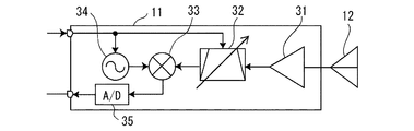
また、図3は、図1に示した各受信モジュール11の内部構成を示す図であって、受信モジュール11も内部に局部発振器34や周波数変換器33を有し、各モジュールごとにレーダ、ECM、通信等の異なる周波数帯の信号を受信することができるため、モジュール1個単位での開口分割を実現することができる。
受信モジュール11の具体的な動作については、後述する。
なお、このような、モジュールの内部に送信信号生成機能や受信機能を有するタイプのフェーズドアレーアンテナそのものは、例えば、文献「Garrod, “Digita
l Modules for Phased Array Radar” IEEE Inte
rnational Rader Conference,1995.」に示されている。
3 is a diagram showing an internal configuration of each receiving
Specific operation of the receiving
Such a phased array antenna itself having a transmission signal generation function and a reception function inside the module is described in, for example, the document “Garrod,“ Digita ”.
l Modules for Phased Array Radar "IEEE Inte
relational reader conference, 1995. Is shown.
各送信モジュール6は、図1に示すように、送信アンテナ制御部3によって制御され、アレーアンテナ全体として、開口分割や、分割された各開口のビーム形成やビーム走査等が行われる。分割された各開口は、レーダ機能やECM機能、通信機能を実現するための送信アンテナとなる。
本実施の形態における構成上での特徴は、送受信の開口分割寸法を計算する開口寸法計算部2を有することである。
開口寸法計算部2で計算された開口寸法データ102に基づき、送信アレーアンテナ4および受信アレーアンテナ9の開口分割を制御する。詳細な動作は後に述べる。
As shown in FIG. 1, each
A feature of the configuration in the present embodiment is that it has an aperture
Based on the
次に、本実施の形態によるフェーズドアレーアンテナ装置の動作について説明する。
共通ユーザーインターフェース(共通U/I)1は、ユーザーからレーダ、ECM機能、通信機能等の起動が指示されると、開口要求データ101を開口寸法計算部2に送る。
なお、開口要求データとは開口を割り当ててもらう指示を意味する。
レーダ処理部14、ECM処理部15、通信処理部16等自体は、それぞれアンテナを有していないので、アレーアンテナに開口を割り当ててもらう必要がある。
開口寸法計算部2は、起動された電波装置および既に起動中の電波装置に必要な開口寸法を計算し、開口寸法データ102を送信アンテナ制御部3および受信アンテナ制御部8に送る。
Next, the operation of the phased array antenna apparatus according to this embodiment will be described.
The common user interface (common U / I) 1 sends opening
The opening request data means an instruction for assigning an opening.
Since the
The aperture
一方、共通ユーザーインターフェース1は、レーダ処理部14、ECM処理部15、通信処理部16に対して、起動が指示された電波装置に対応する処理部に起動指示データを送る。
各機能の処理部(即ち、レーダ処理部14、ECM処理部15、通信処理部16)は、起動指示データを受け取ると、各機能の周波数/ビーム走査角度/送信信号データを送信アンテナ制御部3に送る。
開口寸法データ102と各機能の周波数/ビーム走査角度/送信信号データ103〜105を受け取った送信アンテナ制御部3は、開口寸法データ102に従って各送信モジュールにレーダ、ECM、通信等の機能を割り当て、各送信モジュールに対して割り当てた機能の送信周波数/送信位相/送信信号データ106を送る。送信位相データは、全体として送信アレーアンテナ4がフェーズドアレーアンテナとして動作すべく、各モジュールに割り当てた機能のビーム走査角度データから算出する。
On the other hand, the
When the processing units of each function (that is, the
The transmission
図2に示すように、送信モジュール6内では、送信信号発生器21は送信信号データに従って送信信号を発生し、励振器22は送信周波数データと送信位相データに従って正弦波の励振信号を発生する。
そして、送信信号と励振信号は、周波数変換器23により混合されてRF信号となり、電力増幅器24により増幅されて送信素子アンテナ7から空間に放射される。
なお、図への記述および説明は省略したが、各処理段で発生する不要波は濾波器(図示なし)で適宜除去される。
複数の送信モジュール6から構成される送信アレーアンテナ4は、図1(b)の開口面から見たイメージに示すように、開口寸法データに従った寸法の送信開口5a〜5cを形成し、それぞれの開口が各機能の送信アンテナとして動作する。
As shown in FIG. 2, in the
The transmission signal and the excitation signal are mixed by the
Although description and explanation in the figure are omitted, unnecessary waves generated in each processing stage are appropriately removed by a filter (not shown).
The transmission array antenna 4 composed of a plurality of
ここで、送信アンテナ制御部3が開口寸法データ102に従って、どのようにして送信開口5a〜5cを形成するのかを、以下に説明しておく。
まず、開口寸法データ102から必要なモジュール数を計算する。これは開口寸法/素子アンテナ前面面積として求めることができる。次に、基本的な開口の形(例えば六角形)と相似形で、かつ必要なモジュール数に近くなるように開口面を区切る。そして、区切られた開口面に含まれるモジュールに、閉口を要求してきた機能(レーダ、ECM、通信等)の送信信号データを送り、その機能のためのモジュールとして動作するように指示する。
Here, how the transmission
First, the required number of modules is calculated from the
一方、開口寸法データ102と各機能の周波数/ビーム走査角度データ103〜105は、受信アンテナ制御部8にも送られ、送信の場合と同様に、各受信モジュールに機能を割り当て、受信周波数/受信位相データ107を送る。
受信位相データは、全体として受信アレーアンテナ9がフェーズドアレーアンテナとして動作すべく、各モジュールに割り当てた機能のビーム走査角度データから算出する。
On the other hand, the
The reception phase data is calculated from the beam scanning angle data of the function assigned to each module so that the
図3に示すように、受信モジュール11内では、受信素子アンテナ12から入力した受信信号は、低雑音増幅器31で増幅され、受信周波数データに従って通過帯域が変更された周波数可変バンドパスフィルタ32により受信周波数付近の信号のみが通過する。
局部発振器34は、受信モジュールへの受信周波数データと受信位相データに従って正弦波の局発信号を発生する。
受信信号と局発信号は、周波数変換器33により混合されてベースバンド信号となり、A/D変換器35によってデジタルデータに変換されて受信信号データ108となる。
なお、送信モジュールの場合と同様に、各処理段で発生する不要波は濾波器(図示なし)で適宜除去される。
As shown in FIG. 3, in the
The
The reception signal and the local oscillation signal are mixed by the
As in the case of the transmission module, unnecessary waves generated at each processing stage are appropriately removed by a filter (not shown).
共通受信信号処理部13では、受信モジュールへの機能割り当てデータ109に従って受信モジュールからの受信信号を合成し、各機能ごとの受信信号データ110〜112を生成する。
各機能ごとの受信信号データは、レーダ処理部14、ECM処理部15、通信処理部16に送られ、それぞれの処理部で各機能の処理を行い、表示データとして共通ユーザーインターフェース1に送られて表示される。
The common reception
The received signal data for each function is sent to the
ここで、レーダ処理部14、ECM処理部15および通信処理部16で行われる処理の例について説明する。
レーダ処理部14で行われる処理としては、例えば、次のようなものがある。
まず、周波数データ/ビーム走査角度データ/送信信号データ113を送信アンテナ制御部3に送り、送信信号を送信させる。
次に、目標物からの反射波を含んだ受信信号データ110を共通受信信号処理部13から受け取り、これを検波して目標物からの反射波(目標信号)を検出する。
Here, an example of processing performed by the
Examples of processing performed by the
First, frequency data / beam scanning angle data /
Next, the
目標信号が見つからない場合は、ビームの方向を変えて(即ち、ビーム走査角度データを送信アンテナ制御部と受信アンテナ制御部に送って)受信・検波し、目標信号が見つかるまで繰り返す。
目標信号を発見したら、送信信号を送信してから目標信号が受信されるまでの時間を計測して、目標までの距離を算出(目標距離= [送信信号を送信してから目標信号が受信
されるまでの時間]×[光速]÷2)する。
また、ビームの走査角度から目標の方位を求める。
このようにして求めた目標物の方位と距離を、レーダ機能における表示データ113として共通ユーザーインタ一フェース1に出力する。
When the target signal is not found, the direction of the beam is changed (that is, the beam scanning angle data is sent to the transmission antenna control unit and the reception antenna control unit), reception and detection are repeated until the target signal is found.
When the target signal is found, measure the time from when the transmission signal is transmitted until the target signal is received, and calculate the distance to the target (target distance = [the target signal is received after the transmission signal is transmitted) Time until lapse] x [speed of light] ÷ 2).
Further, the target azimuth is obtained from the beam scanning angle.
The direction and distance of the target obtained in this way are output to the
ECM処理部15で行われる処理とは、例えば次のようなものである。
まず、共通受信信号処理部13から受信信号111を受け取って検波し、妨害対象である相手レーダ信号を検出する。
相手レーダ信号が見つからない場合は、ビームの方向を変えて(即ち、ビーム走査角度データを受信アンテナ制御部に送って)受信・検波し、相手レーダ信号が見つかるまで繰
り返す。
相手レーダ信号を発見したら、その諸元(パルス繰返し周期、パルス幅、変調方式等)を分析する。
そして、分析したこれらの諸元に基づき、妨害信号を生成し、送信信号データとして送信アンテナ制御部3に送って妨害波を送信する。
共通ユーザーインターフェース1に対しては、相手レーダの方向や諸元等を表示データ114として出力する。
The processing performed by the
First, the
If the partner radar signal is not found, the beam direction is changed (that is, the beam scanning angle data is sent to the receiving antenna control unit), reception and detection are repeated until the partner radar signal is found.
When the partner radar signal is found, its specifications (pulse repetition period, pulse width, modulation method, etc.) are analyzed.
Based on these analyzed specifications, an interference signal is generated and transmitted as transmission signal data to the transmission
For the
通信処理部16で行われる処理とは、例えば、次のようなものである。
共通ユーザーインターフェース1は、PC端末のような装置であり、文字データ、画像データ、音声データといったデータを扱うことができる。
まず、共通ユーザーインターフユース1から通信機能の起動指示があると、通信処理部16は、パイロット信号を送信信号データとして送信アンテナ制御部3に送り、送信アンテナ制御部3は、その信号を空間に送信し、通信相手を探して通信を確立する。
この通信を確立する動作には、送信アンテナのビーム走査角度を変えて送信し、通信相手の方向を探す処理も含む。
The processing performed by the
The
First, when there is a communication function activation instruction from the
The operation for establishing the communication includes a process of transmitting by changing the beam scanning angle of the transmission antenna and searching for the direction of the communication partner.
このようにして通信が確立された後、共通ユーザーインターフェース1からは通信内容である文字データ、画像データ、音声データなどが通信処理部16に送られ、通信処理部16では、それをコーディング(符号化)する。
この符号化されたデータを送信信号データとして送信アンテナ制御部3に送り、空間に送信する。
また、受信側の処理では、通信処理部16は、共通受信信号処理部13から受信信号112を受け取ってデコーディング(復号化)し、復号化した文字データ、画像データ、音声データ等を表示データ115として共通ユーザーインターフェース1に出力する。
After the communication is established in this way, the
The encoded data is sent as transmission signal data to the transmission
In the processing on the receiving side, the
ところで、「機能ごとの受信信号データ」とは、「それぞれの機能を割り当てられた開口ごとにビームを形成した後の受信信号」を意味する。
それぞれの開口は多数の受信モジュールで構成されているので、共通受信信号処理部13では、個々の受信モジュールからの受信信号108を各機能に割り当てられた開口ごとに集めてビーム形成する処理を行う。
「表示データ」とは、レーダの場合では目標物の方位と距離であり、共通ユーザーインターフェース1ではレーダスクリーンのような方法で画像を用いて表示することを想定している。
また、ECMの表示データは、相手レーダの方向と信号諸元等であり、文字や画像を利用して表示する。
また、通信での表示データは、受信した文字、画像、音声等のデータであり、共通ユーザーインターフェース1にはキーボード、表示装置、マイクやヘッドホン等が備えてあり、電子メールや電話、FAXなどとして使われることを想定している。
By the way, “received signal data for each function” means “received signal after forming a beam for each aperture to which each function is assigned”.
Since each aperture is composed of a large number of receiving modules, the common received
“Display data” is the direction and distance of a target in the case of radar, and it is assumed that the
Further, the display data of the ECM is the direction and signal specifications of the other party radar, and is displayed using characters and images.
In addition, the communication display data is data such as received characters, images, and voices. The
次に、本発明において最も特徴的で重要な部分である開口寸法計算部2の動作について、図4のフローチャートを用いて説明する。
共通ユーザーインターフェース1から開口要求があると、開口寸法計算部2は、後に示すような計算方法で所要ERP(Effective Radiation Power;実効輻射電力)を計算す
る(ステップ201)。
次に、ビーム幅は、広い方が望ましい場合とそうでない場合(即ち、狭い方が望ましい場合)とで条件分岐する(ステップ202)。
ECM機能における妨害目標の方向や通信機能における通信相手の方向が不明の場合は、広いビーム幅の方が望ましい。このような場合には、所要ERPから所要開口寸法を計算する(ステップ207)。
Next, the operation of the
When there is an opening request from the
Next, conditional branching is performed depending on whether the wider beam width is desirable or not (that is, when the smaller beam width is desirable) (step 202).
When the direction of the disturbance target in the ECM function or the direction of the communication partner in the communication function is unknown, a wider beam width is desirable. In such a case, the required opening dimension is calculated from the required ERP (step 207).
一方、通信機能において通信相手の方向が既知で通信の秘匿性を高めたい場合や、レーダ機能の場合は、ビーム幅が狭い方がよく、このような場合には所要ビーム幅から開口寸法を計算する(ステップ203)。
次に、ビーム幅から計算した開口寸法を用いて得られるERP(実効輻射電力)を計算する(ステップ204)。
得られるERPが所要ERPより大きいかどうかで条件分岐し(205)、得られるERPが所要ERPより大きい場合は所要ビーム幅から計算した開口寸法を所要開口寸法とする(ステップ206)。
On the other hand, if the direction of the communication partner is known in the communication function and you want to improve the confidentiality of the communication, or in the case of the radar function, it is better to have a narrow beam width. In such a case, the aperture size is calculated from the required beam width. (Step 203).
Next, ERP (effective radiation power) obtained using the aperture size calculated from the beam width is calculated (step 204).
Conditional branching is performed depending on whether or not the obtained ERP is larger than the required ERP (205). If the obtained ERP is larger than the required ERP, the aperture size calculated from the required beam width is set as the required aperture size (step 206).
また、得られるERPが所要ERPより小さい場合は、所要ERPから所要開口寸法を計算する(ステップ207)。
最後に、このようにして求めた所要開口寸法(即ち、ステップ206およびステップ207で求めた所要開口寸法)が、アレーアンテナの未使用開口部分に確保可能かどうかで条件分岐し(ステップ208)、確保可能な場合は所要寸法の開口を確保して終了する(ステップ209)。
一方、既に動作中の機能の開口によって所要開口寸法が確保できない場合には、他に動作中の機能の有無で条件分岐し(210)、他に動作中の機能が無い場合にはアレーアンテナ全面を確保して終了する(ステップ211)。
一方、他に動作中の機能がある場合には、優先度の低い機能を停止し(ステップ212)、未使用開口面積を増大させて再び所要開口寸法を確保可能か判断する(ステップ208)。
If the obtained ERP is smaller than the required ERP, the required opening dimension is calculated from the required ERP (step 207).
Finally, a conditional branch is made depending on whether or not the required aperture size obtained in this way (that is, the required aperture size obtained in
On the other hand, if the required opening size cannot be secured due to the opening of the function already in operation, the condition branches depending on the presence of another function in operation (210), and if there is no other function in operation, the entire array antenna And finishes (step 211).
On the other hand, if there is another function in operation, the low priority function is stopped (step 212), and it is determined whether the required opening dimension can be secured again by increasing the unused opening area (step 208).
所要ERP計算(201)は次のように行う。
1)レーダの場合
以下の式(1)に示すように、受信系の最小受信感度、受信アンテナ利得、最大探知距離、想定目標のRCS(Radar Cross Section:レーダ反射断面積)から所要ERPを計
算する。
ERPRADAR = (4π)3Pr_minR4 max/Grλ2σ ・・・ 式(1)
ここで、
Pr_min:最小受信感度[W]
Rmax:最大探知距離[m]
Gr:受信アンテナ利得
λ:波長[m]
σ:想定目標のRCS[m2]
The required ERP calculation (201) is performed as follows.
1) In the case of radar As shown in the following equation (1), the required ERP is calculated from the minimum receiving sensitivity of the receiving system, the receiving antenna gain, the maximum detection distance, and the assumed target RCS (Radar Cross Section). To do.
ERP RADAR = (4π) 3 P r — min R 4 max / G r λ 2 σ Equation (1)
here,
P r_min : Minimum receiving sensitivity [W]
R max : Maximum detection distance [m]
G r : receiving antenna gain λ: wavelength [m]
σ: Assumed target RCS [m 2 ]
2)ECM機能の場合
以下の式(2)に示すように、仮の開口寸法で受信したり、他のESM(Electronic Support Measure)装置で観測した相手レーダ波の電力密度と、プラットホームも含めた自分のRCS(Radar Cross Section)から所要ERPを計算する。
ERPECM=PTARGET σ0 × α ・・・ 式(2)
ここで、
PTARGET:相手レーダ波の電力密度[W/m2]
σ0:自分のプラットホームのRCS[m2]
α:妨害を有効とするためのマージン係数
2) In the case of the ECM function As shown in the following formula (2), including the platform and the power density of the other radar wave received with a temporary aperture size or observed with another ESM (Electronic Support Measure) device Calculate the required ERP from your own RCS (Radar Cross Section).
ERP ECM = P TARGET σ 0 × α (2)
here,
P TARGET : Power density of the partner radar wave [W / m2]
σ 0 : RCS [m2] of own platform
α: Margin factor for effective interference
3)通信機能の場合
以下の式(3)に示すように、仮の開口寸法で受信した通信相手の受信感度、通信相手までの距離、通信相手の受信アンテナ利得から所要ERPを計算する。通信相手までの距
離が不明な場合は想定する最大値とする。
ERPCOM = (4π)2PC_minR2/GCλ2 ・・・ 式(3)
ここで、
PC_min:通信相手の受信感度[W]
R:通信相手までの距離[m]
GC:通信相手の受信アンテナ利得
λ:波長[m]
3) In the case of a communication function As shown in the following formula (3), the required ERP is calculated from the reception sensitivity of the communication partner received at the temporary opening size, the distance to the communication partner, and the reception antenna gain of the communication partner. If the distance to the communication partner is unknown, assume the maximum value.
ERP COM = (4π) 2 PC_min R 2 / G C λ 2 Formula (3)
here,
PC_min : Reception sensitivity of communication partner [W]
R: Distance to communication partner [m]
G C : Receiving antenna gain of communication partner λ: Wavelength [m]
これらの計算に必要な「自分と相手の電波機器の特性や距離、所要ビーム幅などの情報」は、オペレーターが指示して共通ユーザーインターフェース1からの開口要求データ101と共に送るか、各装置のデフォルト情報(即ち、各装置の初期設定値)として開口寸法計算部2で保持しておく。
The information necessary for these calculations, such as the characteristics and distance of the radio equipment of the other party and the other party, and the required beam width, is sent by the operator along with the
所要ビーム幅からの開口寸法計算(ステップ203)は次式ように行う。
水平開口寸法DH= λ/BH ・・・ 式(4)
垂直開口寸法DV= λ/BV ・・・ 式(5)
ここで、
BH:所要水平ビーム幅[rad]
BV:所要垂直ビーム幅[rad]
λ:波長[m]
開口寸法からのERP計算(204)は次式のように行う。
ERP = 4π(DHDV)2P0/λ2 ・・・ 式(6)
ここで、
P0:アレーアンテナの単位面積当たりの送信電力
(=1素子の送信電力/1素子の占める面積)
The aperture size calculation (step 203) from the required beam width is performed as follows.
Horizontal aperture dimension D H = λ / B H (4)
Vertical opening dimension D V = λ / B V (5)
here,
B H : Required horizontal beam width [rad]
B V : Required vertical beam width [rad]
λ: wavelength [m]
The ERP calculation (204) from the opening dimension is performed as follows.
ERP = 4π (D H D V ) 2 P 0 / λ 2 Formula (6)
here,
P 0 : Transmit power per unit area of the array antenna
(= Transmission power of 1 element / area occupied by 1 element)
所要ERPから所要開口寸法の計算(207)は、以下の式(7)のように行う。
A =λ(ERP/4πP0)1/2 ・・・ 式(7)
ここで、A:所要開口面積
ERP:所要ERP
P0:アレーアンテナの単位面積当たりの送信電力
(=1素子の送信電力/1素子の占める面積)
式(7)は所要開口面積しか与えないので、アレーアンテナが正方形に近く、ビーム形状に特に条件が無い場合は、次式(8)のように水平寸法と垂直寸法が等しくなるように計算する。
DH = DV= A1/2 ・・・ 式(8)
The calculation (207) of the required opening size from the required ERP is performed as in the following equation (7).
A = λ (ERP / 4πP 0 ) 1/2 (7)
Here, A: Required opening area ERP: Required ERP
P 0 : Transmit power per unit area of the array antenna
(= Transmission power of 1 element / area occupied by 1 element)
Since Expression (7) gives only the required aperture area, when the array antenna is close to a square and there is no particular condition on the beam shape, calculation is performed so that the horizontal dimension and vertical dimension are equal as in the following Expression (8). .
DH = DV = A1 / 2 ... Formula (8)
また、アレーアンテナが六角形等の場合は、アレーアンテナと相似形で、面積が式(7)で計算した所要開口面積と等しくなるような形状としてもよい。
また、水平ビーム幅または垂直ビーム幅に所要の条件がある場合は、条件のある方向の寸法を式(4)または式(5)で計算し、求めた寸法を所要開口面積から除算して他方の寸法を定めてもよい。
また、開口寸法計算部2は、所要実効輻射電力から第1の開口面積を計算すると共に、所要ビーム幅から第2の開口面積を計算し、計算された第1の開口面積と第2の開口面積のうち大きい方を、複数の電波装置に割り当てる開口面積としてもよい。
所要ERPと所要ビーム幅の両方から計算した開口面積のうち大きい方を用いる場合、一方については過剰性能であるが、他方については過不足ない性能となり、双方について所要以上の性能を確保するという規範で開口面積を決定する場合における最小の開口面積となる。
Further, when the array antenna is a hexagon or the like, it may have a shape similar to the array antenna so that the area is equal to the required opening area calculated by Expression (7).
If there is a required condition for the horizontal beam width or the vertical beam width, the dimension in the direction with the condition is calculated by formula (4) or formula (5), and the obtained dimension is divided from the required aperture area to The dimensions may be defined.
The
When using the larger one of the aperture areas calculated from both the required ERP and the required beam width, the one is excessive performance, but the other is not excessive or insufficient, and the norm of ensuring the performance more than required for both. Is the minimum opening area when determining the opening area.
なお、これらの計算方法は一例であり、例えばレーダは受信アンテナの開口によっても探知性能が左右されるので、送受で開口の分割寸法を同一にすることを想定して所要性能から開口寸法を計算してもよい。
また、レーダ、ECM、通信等の機能はそれぞれ1系統ずつとして説明したが、レーダ
処理部14、ECM処理部15、通信処理部16の数を増やして、複数のレーダ機能、複数のECM機能、複数の通信機能を実現することもできる。このような場合においても図4のフローチャートを用いて、それぞれの機能に割り当てる開口寸法を計算することができる。
These calculation methods are only examples. For example, the detection performance of a radar is affected by the aperture of the receiving antenna. Therefore, the aperture size is calculated from the required performance assuming that the split size of the aperture is the same for transmission and reception. May be.
Further, the functions of radar, ECM, communication, etc. have been described as one system each. However, the number of
以上説明したように、本実施の形態によるフェーズドアレーアンテナ装置は、2次元配列された複数の送信モジュール6で構成された送信アンテナ4と2次元配列された複数の受信モジュール11で構成された受信アンテナ9とを有し、送信アンテナ4および受信アンテナ9の開口を分割することにより使用する複数の電波装置の機能を実現するフェーズドアレーアンテナ装置であって、複数の電波装置が必要とする開口寸法を計算する開口寸法計算部2と、開口寸法計算部2の計算結果に基づいて送信アンテナ4の開口を分割すると共に、分割された各開口のビーム形成やビーム走査の制御を行う送信アンテナ制御部3と、開口寸法計算部2の計算結果に基づいて受信アンテナ9の開口を分割し、複数の電波装置から受信する複数の受信信号を複数の電波装置の各機能に対応して制御する受信アンテナ制御部8を備え、開口寸法計算部2は、複数の電波装置が必要とする実効輻射電力、ビーム幅、あるいはその両方を用いて、複数の電波装置に割り当てる開口寸法を計算する。
As described above, the phased array antenna apparatus according to the present embodiment has a transmission antenna 4 constituted by a plurality of
また、開口寸法計算部2は、下記の式に基づいて各電波装置に割り当てる所要開口面積を計算する。
A = λ(ERP/4πP0)1/2
ここで、A:所要開口面積 λ:波長 ERP:所要実効輻射電力
P0:アレーアンテナの単位面積当たりの送信電力
また、開口寸法計算部2は、下記の式に基づいて各電波装置に割り当てる所要開口寸法を計算する。
水平開口寸法=波長/所要水平ビーム幅
垂直開口寸法=波長/所要垂直ビーム幅
また、開口寸法計算部2は、所要実効輻射電力から第1の開口面積を計算すると共に、所要ビーム幅から第2の開口面積を計算し、計算された第1の開口面積と第2の開口面積のうち大きい方を、複数の電波装置に割り当てる開口面積とする。
また、複数の電波装置は、レーダ、ECMあるいは通信の機能を有する装置である。
Moreover, the opening
A = λ (ERP / 4πP 0 ) 1/2
Where A: required aperture area λ: wavelength ERP: required effective radiation power
P 0 : Transmission power per unit area of the array antenna Further, the
Horizontal aperture size = wavelength / required horizontal beam width Vertical aperture size = wavelength / required vertical beam width In addition, the
The plurality of radio wave devices are devices having a radar, ECM, or communication function.
また、電波装置がレーダの場合、下記式に基づいて実効輻射電力(ERPRADAR)を計算する。
ERPRADAR= (4π)3Pr_minR4 max/Grλ2σ
ここで、Pr_min:最小受信感度[W] Rmax:最大探知距離[m]
Gr:受信アンテナ利得 λ:波長[m] σ:想定目標のRCS[m2]
When the radio wave device is a radar, the effective radiated power (ERP RADAR ) is calculated based on the following equation.
ERP RADAR = (4π) 3 P r — min R 4 max / G r λ 2 σ
Here, P r — min: minimum reception sensitivity [W] R max : maximum detection distance [m]
G r : Receive antenna gain λ: Wavelength [m] σ: Assumed target RCS [m 2 ]
また、電波装置がECMの場合、下記式に基づいて実効輻射電力(ERPECM)を計算する。
ERPECM =PTARGET σ0 × α
ここで、PTARGET:相手レーダ波の電力密度[W/m2]
σ0:自分のプラットホームのRCS[m2]
α:妨害を有効とするためのマージン係数
Further, when the radio wave device is an ECM, an effective radiation power (ERP ECM ) is calculated based on the following formula.
ERP ECM = P TARGET σ 0 × α
Here, P TARGET : Power density of partner radar wave [W / m 2 ]
σ 0 : RCS [m 2 ] of own platform
α: Margin factor for effective interference
また、電波装置が通信装置の場合、下記式に基づいて実効輻射電力(ERPCOM)を
計算する。
ERPCOM = (4π)2PC_minR2/GCλ2
ここで、PC_min:通信相手の受信感度[W]
R:通信相手までの距離[m] GC:通信相手の受信アンテナ利得
λ:波長[m]
When the radio wave device is a communication device, the effective radiated power (ERP COM ) is calculated based on the following equation.
ERP COM = (4π) 2 PC_min R 2 / G C λ 2
Here, P C_min : Reception sensitivity of communication partner [W]
R: Distance to communication partner [m] G C : Reception antenna gain of communication partner λ: Wavelength [m]
本実施形態によると、所要ERPや所要ビーム幅に基づいて、レーダ、ECM、通信等の各機能に割り当てる開口寸法を決定するので、各機能の性能を過不足なく実現することができ、限られたアレーアンテナの開口を有効活用することができる。
即ち、同じ寸法の開口ならば、固定分割の場合に比べてより多数のレーダ、ECM、通信等の機能を実現できるという利点がある。
また、実現する機能の数が一定ならば、最小のアレーアンテナで、全ての機能を実現することができるという利点がある。
According to the present embodiment, since the aperture size assigned to each function such as radar, ECM, and communication is determined based on the required ERP and the required beam width, the performance of each function can be realized without excess and deficiency. The aperture of the array antenna can be used effectively.
That is, if the openings have the same size, there is an advantage that a larger number of functions such as radar, ECM, and communication can be realized as compared with the case of fixed division.
Further, if the number of functions to be realized is constant, there is an advantage that all functions can be realized with the minimum array antenna.
即ち、本実施の形態によると、開口寸法計算部2は、複数の電波装置が必要とする実効輻射電力、ビーム幅、あるいはその両方を用いて、複数の電波装置に割り当てる開口寸法を計算するので、共用して使用する各電波装置に必要十分な性能を与える最適な開口の分割寸法(即ち、最適な分割開口面積)を決定し、各電波装置の所要性能を過不足なく実現することができると共に、無駄な消費電力を無くすことができる。
That is, according to the present embodiment, the aperture
なお、従来では、各電波装贋のアンテナは個別に装備されていたため、レーダや衛星通信設備のような回転するアンテナの場合、装置間でアンテナが正対して強い干渉が生じることがある。そのため、従来では他の装置のアンテナがある方向に対しては、レーダを停止するなどの措置がとられていた。
一方、本実施の形態によるフェーズドアレイアンテナ装置では、各電波装置のアンテナは同一平面内に配置されるので、正対することはないし、また、送信は全て送信アレーアンテナ、受信は全て受信アレーアンテナで纏めて行うので、送信アレーアンテナと受信アレーアンテナ間の干渉のみを防止すれば、電波装置間の電磁干渉は無くなる。
Conventionally, since the antenna of each radio equipment is individually provided, in the case of a rotating antenna such as a radar or a satellite communication facility, strong interference may occur between the antennas facing each other. For this reason, conventionally, measures such as stopping the radar have been taken in the direction in which the antennas of other devices are located.
On the other hand, in the phased array antenna apparatus according to the present embodiment, the antennas of the respective radio wave apparatuses are arranged in the same plane, so that they do not face each other, and all transmission is a transmission array antenna and all reception is a reception array antenna. Since they are performed together, if only interference between the transmitting array antenna and the receiving array antenna is prevented, electromagnetic interference between radio wave devices is eliminated.
本発明は、アレーアンテナの開口を分割して複数の電波装置で共用使用するフェーズドアレーアンテナ装置であって、各電波装置に必要十分な性能を与える開口の分割寸法を決定すると共に、無駄な消費電力を無くすことができるフェーズドアレーアンテナ装置の実現に有用である。 The present invention relates to a phased array antenna device that divides an array antenna aperture and uses it in common with a plurality of radio wave devices, and determines the division size of the aperture that gives each radio wave device necessary and sufficient performance, and wasteful consumption. This is useful for realizing a phased array antenna device that can eliminate power.
1 共通ユーザーインターフェース 2 開口寸法計算部
3 送信アンテナ制御部 4 送信アレーアンテナ
5 送信アレーアンテナの開口面
5a レーダ機能を割り当てた送信開口
5b ECM機能を割り当てた送信開口
5c 通信機能を割り当てた送信開口
6 送信モジュール 7 送信素子アンテナ
8 受信アンテナ制御部 9 受信アレーアンテナ
10 受信アレーアンテナを開口面
10a レーダ機能を割り当てた受信開口
10b ECM機能を割り当てた受信開口
10c 通信機能を割り当てた受信開口
11 受信モジュール 12 受信素子アンテナ
13 共通受信信号処理部 14 レーダ処理部
15 ECM処理部 16 通信処理部
21 送信信号発生器 22 励振器
23 周波数変換器 24 電力増幅器
31 低雑音増幅器 32 周波数可変バンドパスフィルタ
33 周波数変換器 34 局部発振器
35 A/D変換器
101 開口要求データ
102 開口寸法データ
103 レーダ機能の周波数/ビーム走査角度/送信信号データ
104 ECM機能の周波数/ビーム走査角度/送信信号データ
105 通信機能の周波数/ビーム走査角度/送信信号データ
106 各送信モジュールへの送信周波数/送信位相/送信信号データ
107 各受信モジュールへの受信周波数/受信位相データ
108 各受信モジュールからの受信信号データ
109 受信モジュールの機能割り当てデータ
110 レーダ機能の受信信号データ
111 ECM機能の受信信号データ
112 通信機能の受信信号データ
113 レーダ機能の起動指示/表示データ(双方向)
114 ECM機能の起動指示/表示データ(双方向)
115 通信機能の起動指示/表示データ(双方向)
DESCRIPTION OF SYMBOLS 1 Common user interface 2 Aperture size calculation part 3 Transmission antenna control part 4 Transmission array antenna 5 Aperture surface of transmission array antenna 5a Transmission opening assigned radar function 5b Transmission opening assigned ECM function 5c Transmission opening assigned communication function 6 Transmitting module 7 Transmitting element antenna 8 Receiving antenna control unit 9 Receiving array antenna 10 Opening surface of receiving array antenna 10a Receiving aperture assigned with radar function 10b Receiving aperture assigned with ECM function 10c Receiving aperture assigned with communication function 11 Receiving module 12 Reception element antenna 13 Common reception signal processing unit 14 Radar processing unit 15 ECM processing unit 16 Communication processing unit 21 Transmission signal generator 22 Exciter 23 Frequency converter 24 Power amplifier 31 Low noise amplifier 32 Frequency variable bandpass Filter 33 Frequency converter 34 Local oscillator 35 A / D converter 101 Aperture request data 102 Aperture size data 103 Radar function frequency / beam scanning angle / transmission signal data 104 ECM function frequency / beam scanning angle / transmission signal data 105 Communication Function frequency / beam scanning angle / transmission signal data 106 Transmission frequency / transmission phase / transmission signal data to each transmission module 107 Reception frequency / reception phase data to each reception module 108 Reception signal data from each reception module 109 Reception module Function allocation data 110 Radar function received signal data 111 ECM function received signal data 112 Communication function received signal data 113 Radar function start instruction / display data (bidirectional)
114 ECM function activation instruction / display data (bidirectional)
115 Communication function activation instruction / display data (bidirectional)
Claims (8)
前記複数の電波装置のそれぞれが必要とする開口寸法を計算する開口寸法計算部と、
前記開口寸法計算部の計算結果に基づいて前記送信アンテナの開口を分割すると共に、分割された各開口のビーム形成やビーム走査の制御を行う送信アンテナ制御部と、
前記開口寸法計算部の計算結果に基づいて前記受信アンテナの開口を分割し、前記複数の電波装置から受信する複数の受信信号を前記複数の電波装置の各機能に対応して制御する受信アンテナ制御部を備え、
前記開口寸法計算部は、それぞれの電波装置が必要とする所要実効輻射電力を計算し、前記送信アンテナによる実効輻射電力が前記所要実効輻射電力以上となる前記開口寸法を、前記所要実効輻射電力、所要ビーム幅あるいはその両方を用いて計算することを特徴とするフェーズドアレーアンテナ装置。 By having a transmission antenna composed of a plurality of transmission modules arranged two-dimensionally and a reception antenna composed of a plurality of reception modules arranged two-dimensionally, and dividing the aperture of the transmission antenna and the reception antenna A phased array antenna device that realizes the functions of a plurality of radio wave devices to be used,
An aperture size calculation unit for calculating an aperture size required by each of the plurality of radio wave devices;
A transmission antenna control unit that divides the aperture of the transmission antenna based on the calculation result of the aperture size calculation unit, and controls beam formation and beam scanning of each of the divided apertures;
Receiving antenna control that divides the opening of the receiving antenna based on the calculation result of the opening size calculation unit and controls a plurality of received signals received from the plurality of radio wave devices corresponding to each function of the plurality of radio wave devices Part
The aperture size calculation unit calculates a required effective radiant power required by each radio wave device , and sets the aperture size at which the effective radiated power by the transmission antenna is equal to or greater than the required effective radiant power, the required effective radiant power, A phased array antenna apparatus characterized by calculating using a required beam width or both .
A = λ(ERP/4πP0)1/2
ここで、
A:所要開口面積 λ:波長 ERP:所要実効輻射電力
P0:アレーアンテナの単位面積当たりの送信電力 2. The phased unit according to claim 1, wherein the opening size calculation unit calculates a required opening area by the following formula using the required effective radiation power, and calculates the opening size from the required opening area. Array antenna device.
A = λ (ERP / 4πP 0 ) 1/2
here,
A: Required aperture area λ: Wavelength ERP: Required effective radiation power P 0 : Transmit power per unit area of array antenna
水平開口寸法=波長/所要水平ビーム幅
垂直開口寸法=波長/所要垂直ビーム幅 The aperture size calculation unit calculates the horizontal aperture size and the vertical aperture size calculated by the following formula using the required beam width from the horizontal aperture size and the vertical aperture size, and the effective radiation power by the transmitting antenna is The phased array antenna apparatus according to claim 1 , wherein the opening size is set when the required effective radiation power is larger .
Horizontal aperture size = wavelength / required horizontal beam width Vertical aperture size = wavelength / required vertical beam width
計算された前記第1の開口面積と前記第2の開口面積のうちの面積の大きい方から前記開口寸法を計算することを特徴とする請求項1に記載のフェーズドアレーアンテナ装置。 The opening size calculation unit is configured to calculate the first opening area from the required effective radiated power, to calculate the second opening area from the desired beam width,
The phased array antenna apparatus according to claim 1 , wherein the opening dimension is calculated from a larger one of the calculated first opening area and the second opening area.
ERPRADAR= (4π)3Pr_minR4 max/Grλ2σ
ここで、
Pr_min:最小受信感度[W] Rmax:最大探知距離[m]
Gr:受信アンテナ利得 λ:波長[m]
σ:想定目標のRCS[m2] The opening dimension calculation unit, if the previous SL Telecommunications device for apparatus having a radar function, any one of the preceding claims, characterized in that to calculate the required effective radiated power (ERP RADAR) based on the following formula The phased array antenna apparatus according to item 1 .
ERP RADAR = (4π) 3 P r — min R 4 max / G r λ 2 σ
here,
P r — min : Minimum reception sensitivity [W] R max : Maximum detection distance [m]
G r : receiving antenna gain λ: wavelength [m]
σ: Assumed target RCS [m 2 ]
ERPECM =PTARGET σ0 × α
ここで、
PTARGET:相手レーダ波の電力密度[W/m2]
σ0:自分のプラットホームのRCS[m2]
α:妨害を有効とするためのマージン係数 The opening dimension calculation unit, if the previous SL Telecommunications equipment device having the ECM function, any one of the preceding claims, characterized in that to calculate the required effective radiated power (ERP ECM) based on the following formula The phased array antenna apparatus according to item 1 .
ERP ECM = P TARGET σ 0 × α
here,
P TARGET : Power density of partner radar wave [W / m 2 ]
σ 0 : RCS [m 2 ] of own platform
α: Margin factor for effective interference
ERPCOM = (4π)2PC_minR2/GCλ2
ここで、
PC_min:通信相手の受信感度[W] R:通信相手までの距離[m]
GC:通信相手の受信アンテナ利得 λ:波長[m] The opening dimension calculation unit, if the previous SL Telecommunications device of a device having a communication function, any one of the preceding claims, characterized in that to calculate the required effective radiated power (ERP COM) on the basis of the following formula The phased array antenna apparatus according to item 1 .
ERP COM = (4π) 2 PC_min R 2 / G C λ 2
here,
PC_min : Reception sensitivity of communication partner [W] R: Distance to communication partner [m]
G C : Receiving antenna gain of communication partner λ: Wavelength [m]
Priority Applications (1)
| Application Number | Priority Date | Filing Date | Title |
|---|---|---|---|
| JP2011056540A JP5704980B2 (en) | 2011-03-15 | 2011-03-15 | Phased array antenna device |
Applications Claiming Priority (1)
| Application Number | Priority Date | Filing Date | Title |
|---|---|---|---|
| JP2011056540A JP5704980B2 (en) | 2011-03-15 | 2011-03-15 | Phased array antenna device |
Publications (2)
| Publication Number | Publication Date |
|---|---|
| JP2012195669A JP2012195669A (en) | 2012-10-11 |
| JP5704980B2 true JP5704980B2 (en) | 2015-04-22 |
Family
ID=47087204
Family Applications (1)
| Application Number | Title | Priority Date | Filing Date |
|---|---|---|---|
| JP2011056540A Active JP5704980B2 (en) | 2011-03-15 | 2011-03-15 | Phased array antenna device |
Country Status (1)
| Country | Link |
|---|---|
| JP (1) | JP5704980B2 (en) |
Families Citing this family (1)
| Publication number | Priority date | Publication date | Assignee | Title |
|---|---|---|---|---|
| JP2016134784A (en) * | 2015-01-20 | 2016-07-25 | 株式会社東芝 | Array antenna |
Family Cites Families (6)
| Publication number | Priority date | Publication date | Assignee | Title |
|---|---|---|---|---|
| JP3456167B2 (en) * | 1999-06-24 | 2003-10-14 | 三菱電機株式会社 | Multifunctional antenna device |
| JP2003066133A (en) * | 2001-08-29 | 2003-03-05 | Mitsubishi Electric Corp | Radar |
| GB0213976D0 (en) * | 2002-06-18 | 2002-12-18 | Bae Systems Plc | Common aperture antenna |
| JP3894490B2 (en) * | 2003-01-06 | 2007-03-22 | 三菱電機株式会社 | Radar apparatus and antenna aperture surface division control method |
| JP3941940B2 (en) * | 2003-02-13 | 2007-07-11 | 三菱電機株式会社 | Broadband active phased array antenna device |
| JP2004279147A (en) * | 2003-03-14 | 2004-10-07 | Toshiba Corp | Antenna device |
-
2011
- 2011-03-15 JP JP2011056540A patent/JP5704980B2/en active Active
Also Published As
| Publication number | Publication date |
|---|---|
| JP2012195669A (en) | 2012-10-11 |
Similar Documents
| Publication | Publication Date | Title |
|---|---|---|
| US11670849B2 (en) | Aimable beam antenna system | |
| JP5449372B2 (en) | Optimize wireless network coverage | |
| US20190229403A1 (en) | Antenna system and communication terminal | |
| Zhu et al. | Unified time-and frequency-domain study on time-modulated arrays | |
| CN108352607B (en) | Phased array antenna | |
| US9213095B2 (en) | Combined direction finder and radar system, method and computer program product | |
| RU132285U1 (en) | MULTI-PURPOSE AUTOMATED RADIO COMMUNICATION NODE | |
| US20200059116A1 (en) | Radio frequency energy-harvesting apparatus | |
| CN114026927A (en) | Angle positioning method, device and equipment | |
| US20170229786A1 (en) | Antenna System and Processing Method | |
| EP3316400B1 (en) | Phase-controlled array system and beam scanning method | |
| Yang et al. | A time-modulated array with digitally preprocessed rectangular pulses for wireless power transmission | |
| CN108306115A (en) | A kind of space-time modulation array antenna system and its production method | |
| JP5704980B2 (en) | Phased array antenna device | |
| Li | Inseparable waveform synthesis in joint communications and radar via spatial-frequency spectrum | |
| Wijenayake et al. | DOA-estimation and source-localization in CR-networks using steerable 2-D IIR beam filters | |
| US11438051B2 (en) | Preconfigured antenna beamforming | |
| US9523770B1 (en) | Multiple frequency parametric sonar | |
| US10218059B2 (en) | Beam-steering antenna deflector | |
| KR102541472B1 (en) | Method and Apparatus for Signal Transmission Capable of Simultaneous Multi-Band Response | |
| KR102541473B1 (en) | Method and Apparatus for Signal Transmission Capable of Simultaneous Multi-Band Response Based on Multi-Dimensional Frequency Synchronization | |
| RU2817766C1 (en) | Adaptive sw band transmission system with phased array based on sdr technology | |
| Eudeline | Survey of active electronically scanned antenna in Thales radars | |
| US20230124953A1 (en) | Information processing device, information processing method, and program | |
| US20240097745A1 (en) | Distributed Configuration of Reconfigurable Intelligent Surfaces |
Legal Events
| Date | Code | Title | Description |
|---|---|---|---|
| A621 | Written request for application examination |
Free format text: JAPANESE INTERMEDIATE CODE: A621 Effective date: 20140207 |
|
| A977 | Report on retrieval |
Free format text: JAPANESE INTERMEDIATE CODE: A971007 Effective date: 20140717 |
|
| A131 | Notification of reasons for refusal |
Free format text: JAPANESE INTERMEDIATE CODE: A131 Effective date: 20140819 |
|
| A521 | Request for written amendment filed |
Free format text: JAPANESE INTERMEDIATE CODE: A523 Effective date: 20141016 |
|
| TRDD | Decision of grant or rejection written | ||
| A01 | Written decision to grant a patent or to grant a registration (utility model) |
Free format text: JAPANESE INTERMEDIATE CODE: A01 Effective date: 20150127 |
|
| A61 | First payment of annual fees (during grant procedure) |
Free format text: JAPANESE INTERMEDIATE CODE: A61 Effective date: 20150224 |
|
| R151 | Written notification of patent or utility model registration |
Ref document number: 5704980 Country of ref document: JP Free format text: JAPANESE INTERMEDIATE CODE: R151 |
|
| R250 | Receipt of annual fees |
Free format text: JAPANESE INTERMEDIATE CODE: R250 |
|
| R250 | Receipt of annual fees |
Free format text: JAPANESE INTERMEDIATE CODE: R250 |
|
| R250 | Receipt of annual fees |
Free format text: JAPANESE INTERMEDIATE CODE: R250 |
|
| R250 | Receipt of annual fees |
Free format text: JAPANESE INTERMEDIATE CODE: R250 |
|
| R250 | Receipt of annual fees |
Free format text: JAPANESE INTERMEDIATE CODE: R250 |
|
| R250 | Receipt of annual fees |
Free format text: JAPANESE INTERMEDIATE CODE: R250 |
|
| R250 | Receipt of annual fees |
Free format text: JAPANESE INTERMEDIATE CODE: R250 |