JP5704342B2 - Solar power plant - Google Patents
Solar power plant Download PDFInfo
- Publication number
- JP5704342B2 JP5704342B2 JP2011244154A JP2011244154A JP5704342B2 JP 5704342 B2 JP5704342 B2 JP 5704342B2 JP 2011244154 A JP2011244154 A JP 2011244154A JP 2011244154 A JP2011244154 A JP 2011244154A JP 5704342 B2 JP5704342 B2 JP 5704342B2
- Authority
- JP
- Japan
- Prior art keywords
- solar cell
- light guide
- guide device
- cell panel
- sunlight
- Prior art date
- Legal status (The legal status is an assumption and is not a legal conclusion. Google has not performed a legal analysis and makes no representation as to the accuracy of the status listed.)
- Active
Links
Images


Classifications
-
- Y—GENERAL TAGGING OF NEW TECHNOLOGICAL DEVELOPMENTS; GENERAL TAGGING OF CROSS-SECTIONAL TECHNOLOGIES SPANNING OVER SEVERAL SECTIONS OF THE IPC; TECHNICAL SUBJECTS COVERED BY FORMER USPC CROSS-REFERENCE ART COLLECTIONS [XRACs] AND DIGESTS
- Y02—TECHNOLOGIES OR APPLICATIONS FOR MITIGATION OR ADAPTATION AGAINST CLIMATE CHANGE
- Y02E—REDUCTION OF GREENHOUSE GAS [GHG] EMISSIONS, RELATED TO ENERGY GENERATION, TRANSMISSION OR DISTRIBUTION
- Y02E10/00—Energy generation through renewable energy sources
- Y02E10/40—Solar thermal energy, e.g. solar towers
-
- Y—GENERAL TAGGING OF NEW TECHNOLOGICAL DEVELOPMENTS; GENERAL TAGGING OF CROSS-SECTIONAL TECHNOLOGIES SPANNING OVER SEVERAL SECTIONS OF THE IPC; TECHNICAL SUBJECTS COVERED BY FORMER USPC CROSS-REFERENCE ART COLLECTIONS [XRACs] AND DIGESTS
- Y02—TECHNOLOGIES OR APPLICATIONS FOR MITIGATION OR ADAPTATION AGAINST CLIMATE CHANGE
- Y02E—REDUCTION OF GREENHOUSE GAS [GHG] EMISSIONS, RELATED TO ENERGY GENERATION, TRANSMISSION OR DISTRIBUTION
- Y02E10/00—Energy generation through renewable energy sources
- Y02E10/50—Photovoltaic [PV] energy
- Y02E10/52—PV systems with concentrators
Description
本発明は、太陽電池パネルを多段に配置した太陽光発電装置に関するものである。 The present invention relates to a solar power generation apparatus in which solar cell panels are arranged in multiple stages.
近年、二酸化炭素の排出による地球温暖化現象に対する危機感が高まってきている。それに伴い、クリーンエネルギー供給源としての太陽電池を利用した太陽光発電装置が注目されている。 In recent years, there is a growing sense of crisis with respect to the global warming phenomenon caused by carbon dioxide emissions. Accordingly, a solar power generation apparatus using a solar cell as a clean energy supply source has attracted attention.
この種の太陽光発電装置としては、特許文献1、特許文献2に記載のように、住宅等の建築物の屋根上にパネル状の太陽電池モジュール(太陽電池パネル)を多数設置したものが広く知られている。
As this kind of solar power generation device, as described in
また、特許文献3に示すように、太陽電池パネルを屋根以外の場所に、例えば日当たりの良い平地等に多数並べて設置することで、大規模な太陽光発電装置を設備することも行われている。
In addition, as shown in
しかし、こうした従来の太陽光発電装置において、特許文献1及び特許文献2に記載の太陽光発電装置では、建築物の屋根上に太陽電池パネルを設置しているため、装置が大掛かりで設置作業に手間がかかるだけでなく、高所作業における安全性の維持が難しいといった課題があった。
However, in such conventional solar power generation devices, in the solar power generation devices described in
また、太陽電池パネルの重量に耐えるのに充分な構造強度を建築物に対して行う必要があるため、その分、全体の建築コストが増大するといった課題もあった。 In addition, since it is necessary to provide the building with sufficient structural strength to withstand the weight of the solar cell panel, there is a problem that the overall construction cost increases accordingly.
この点、特許文献3に記載の太陽光発電装置では、屋根以外の平地等に設置するため、上記のような課題生じない。
しかし、この場合、多数の太陽電池パネルを平地等に並べて配置するために、広大な敷地を必要とする課題があった。特に、土地の有効利用が求められる市街化地域等においては、太陽電池パネルを設置する敷地の単位面積あたりの発電量を可能な限り高める必要があった。
こうした課題は、太陽電池パネルを平屋根上に設置する場合や、比較的狭い空き地などに設置する場合にも同様な課題として存在する。
In this respect, the solar power generation device described in
However, in this case, there is a problem that a large site is required in order to arrange a large number of solar cell panels side by side on a flat ground or the like. In particular, in urbanized areas where the effective use of land is required, it was necessary to increase the amount of power generation per unit area of the site where solar panels were installed as much as possible.
Such a problem also exists as a similar problem when the solar cell panel is installed on a flat roof or when it is installed in a relatively narrow open space.
本発明は、以上のような点を考慮してなされたもので、太陽電池パネルを多段に配置すると共に、太陽電池パネルに太陽光を導く導光装置を装備することで、敷地の有効利用を図り、これにより太陽電池パネルを設置する敷地の単位面積あたりの発電量を格段に向上させることができる、太陽光発電装置を提供することを課題とする。 The present invention has been made in consideration of the above points, and the solar cell panels are arranged in multiple stages and equipped with a light guide device that guides sunlight to the solar cell panels, thereby effectively using the site. Therefore, it is an object of the present invention to provide a solar power generation device that can significantly improve the power generation amount per unit area of a site where a solar cell panel is installed.
前記課題を解決するための本発明は、上下に間隔をおいて多段に配置される複数の太陽電池パネルと、前記各太陽光電池パネルのうち、少なくとも一部の太陽電池パネルに対して太陽光を導く導光装置と、を備えていることを特徴とするものである。 The present invention for solving the above-described problems is a plurality of solar cell panels arranged in multiple stages at intervals in the vertical direction, and at least some of the solar cell panels are exposed to sunlight. And a light guide device for guiding.
本発明によれば、太陽電池パネルを上下に間隔をおいて多段に配置することで、敷地や空き地あるいは平屋根等の単位面積当たりの有効利用を図ることができる。また、少なくとも一部の太陽電池パネルに対して太陽光を導く導光装置を装備することで、多段に配置することで日陰になる太陽電池パネルに太陽光を照射することができる。これにより、太陽電池パネルを設置する敷地の単位面積あたりの発電量を格段に向上させることができる。 ADVANTAGE OF THE INVENTION According to this invention, the effective utilization per unit area, such as a site | area, a vacant land, or a flat roof, can be aimed at by arrange | positioning a solar cell panel in multiple steps at intervals up and down. Moreover, by equipping at least a part of the solar cell panels with a light guide device that guides sunlight, the solar cell panels that are shaded by being arranged in multiple stages can be irradiated with sunlight. Thereby, the electric power generation amount per unit area of the site which installs a solar cell panel can be improved markedly.
本発明の好ましい形態として、前記導光装置は、前記各太陽電池パネルのうち、日陰になる太陽電池パネルに対して太陽光を導くことを特徴としている。
このように、導光装置を、日陰になる太陽電池パネルに対して太陽光を導く構成とすることで、日陰になり易い2段目以降の太陽電池パネルにのみ、太陽光を導くことができる。これにより、1段目の太陽電池パネルを通常の使用形態とすることができる。また、1段目の少なくとも一部が日陰になる場合でもその日陰部分に太陽光を照射することができる。
As a preferred embodiment of the present invention, the light guide device is characterized by guiding sunlight to a solar cell panel that is shaded among the solar cell panels.
Thus, sunlight can be guide | induced only to the solar cell panel after the 2nd step | paragraph which becomes easy to be shaded by setting a light guide device as the structure which guides sunlight with respect to the solar cell panel which becomes shade. . Thereby, a 1st-stage solar cell panel can be made into a normal usage pattern. Even when at least a part of the first stage is shaded, the shaded part can be irradiated with sunlight.
本発明の好ましい形態として、前記導光装置は、上下に間隔をおいて多段に配置される複数の太陽電池パネルのうち、上から二段目以降の太陽電池パネルに対して太陽光を導くことを特徴としている。
このように、導光装置を、上から二段目以降の太陽電池パネルに対して太陽光を導く構成とすることで、上から1段目が日陰にならない場合にはそれを除き、日陰になり易い2段目以降の太陽電池パネルにのみ、太陽光を導くことができる。これにより、1段目の太陽電池パネルを通常の使用形態とすることができる。
As a preferred embodiment of the present invention, the light guide device guides sunlight to the second and subsequent solar cell panels from the top among a plurality of solar cell panels arranged in multiple stages at intervals in the vertical direction. It is characterized by.
In this way, the light guide device is configured to guide sunlight to the solar cell panels at the second and subsequent stages from the top, and when the first stage from the top does not become shade, Sunlight can be guided only to the second and subsequent solar cell panels that are likely to be formed. Thereby, a 1st-stage solar cell panel can be made into a normal usage pattern.
本発明の好ましい形態では、最上段の太陽電池パネルは、その表面が太陽側へ向く形態となるように傾斜しており、2段目以降の太陽電池パネルは前記導光装置で導かれる太陽光と向き合う形態となるように傾斜していることを特徴としている。
このように最上段の太陽電池パネルを、その表面が太陽側へ向く形態で傾斜させ、2段目以降の太陽電池パネルは、導光装置で導かれる太陽光と向き合う形態となるように傾斜させることで、各段の太陽電池パネルのそれぞれが太陽光発電に適した傾斜状態とすることができる。これにより太陽電池パネル全体の発電効率を高めることが可能になる。
In a preferred embodiment of the present invention, the uppermost solar cell panel is inclined so that the surface thereof is directed toward the sun, and the second and subsequent solar cell panels are sunlight guided by the light guide device. It is characterized by being inclined so as to be in a form facing each other.
In this way, the uppermost solar cell panel is inclined so that the surface thereof faces the sun, and the second and subsequent solar cell panels are inclined so as to face the sunlight guided by the light guide device. Thus, each of the solar cell panels at each stage can be in an inclined state suitable for photovoltaic power generation. As a result, the power generation efficiency of the entire solar cell panel can be increased.
本発明の好ましい形態では、前記太陽電池パネルは少なくとも3段に配置され、前記導光装置は、2段目の太陽電池パネルに太陽光を導く第1導光装置と、3段目の太陽電池パネルに太陽光を導く第2導光装置と、を備えていることを特徴としている。
このように、2段目の太陽電池パネルに太陽光を導く第1導光装置と、3段目の太陽電池パネルに太陽光を導く第2導光装置とを設けることで、各段専用の導光装置を配置することができる。これにより各段の太陽電池パネルに太陽光を効率的に導く構成とすることが可能になる。
In a preferred embodiment of the present invention, the solar cell panels are arranged in at least three stages, and the light guide device includes a first light guide device that guides sunlight to a second-stage solar cell panel, and a third-stage solar cell. And a second light guide device for guiding sunlight to the panel.
Thus, by providing the first light guide device that guides sunlight to the second-stage solar cell panel and the second light guide device that guides sunlight to the third-stage solar cell panel, A light guide device can be arranged. Thereby, it becomes possible to set it as the structure which guides sunlight efficiently to the solar cell panel of each step.
本発明の好ましい形態では、前記第1導光装置と第2導光装置は、太陽電池パネルを中間にしてその両側に配置されていることを特徴としている。
このように、第1導光装置と第2導光装置を、太陽電池パネルを中間にしてその両側に配置した場合、太陽光の採光及び導光において、第1導光装置と第2導光装置とが互いに邪魔にならないように配置することができる。これにより、多段の太陽電池パネルに対して太陽光を確実かつ効率的に導くことができる。
In a preferred embodiment of the present invention, the first light guide device and the second light guide device are arranged on both sides of the solar cell panel in the middle.
In this way, when the first light guide device and the second light guide device are arranged on both sides of the solar cell panel in the middle, the first light guide device and the second light guide are used in the daylighting and light guiding of sunlight. The device can be arranged so as not to interfere with each other. Thereby, sunlight can be reliably and efficiently guided to the multi-stage solar cell panel.
本発明の好ましい形態では、前記導光装置が、太陽光を反射させてその反射光を太陽電池パネルへ導く反射板と、反射板の角度調整手段と、を備えていることを特徴としている。
このように、導光装置が、反射板とその反射板の角度調整手段とを備えている構成とした場合、太陽電池パネルの発電効率を十分に高めることができるように、太陽光の導光状態を効率的にかつ有効に制御することができる。
In a preferred embodiment of the present invention, the light guide device includes a reflecting plate that reflects sunlight and guides the reflected light to the solar cell panel, and angle adjusting means of the reflecting plate.
In this way, when the light guide device is configured to include the reflector and the angle adjustment means of the reflector, the light guide of the sunlight is performed so that the power generation efficiency of the solar cell panel can be sufficiently increased. The state can be controlled efficiently and effectively.
本発明の太陽光発電装置によれば、太陽電池パネルを多段に配置すると共に、太陽電池パネルに太陽光を導く導光装置を装備することで、敷地の有効利用を図り、これにより太陽電池パネルを設置する敷地の単位面積あたりの発電量を格段に向上させることができる。 According to the solar power generation device of the present invention, the solar cell panels are arranged in multiple stages and equipped with a light guide device that guides sunlight to the solar cell panel, thereby achieving effective use of the site. The amount of power generation per unit area of the site where the site is installed can be significantly improved.
以下、本発明の実施形態について、図面を参照して説明する。
(実施形態1)
この実施形態1に係る太陽光発電装置は、図1及び図2において、全体として符号10で示している。
Hereinafter, embodiments of the present invention will be described with reference to the drawings.
(Embodiment 1)
The photovoltaic power generation apparatus according to
この太陽光発電装置10は、上下に間隔をおいて3段に配置された複数の太陽電池パネル1と、各太陽電池パネル1を支持する支持基台2と、各太陽光電池パネル1に太陽光を導く導光装置3と、導光装置3を支持する支持部とを備えている。導光装置3は、2段目の太陽電池パネルに対して太陽光を導く第1導光装置31と、3段目の太陽電池パネルに対して太陽光を導く第2導光装置32と、を備えている。次いで、これらの詳細について説明する。
The solar
太陽電池パネル1は、図1に示すように、最上段になる1段目の太陽電池パネル11と、2段目の太陽電池パネル12と、3段目の太陽電池パネル13とを備えている。これらの太陽電池パネルには、一般的な矩形状のものが用いられている。その大きさや重量については特に限定されないが、設置作業をしやすい大きさや重量のものが好ましい。
As shown in FIG. 1, the
1段目の太陽電池パネル11、2段目の太陽電池パネル12、3段目の太陽電池パネル13は、図2に示すように、太陽Sの高度との相対関係に配慮して、それぞれ太陽S側に所定角度傾斜している。この傾斜角度は、太陽電池パネル1の設置緯度に対応させて最も好ましい角度に設定される。
As shown in FIG. 2, the first-stage solar panel 11, the second-stage
これらの太陽電池パネル1を支持する支持基台2は、複数の支柱21と、各支柱21どうしを横方向で連結する連結材22と、を備えている。各支柱21の高さや太さ、強度等に関しては、設置すべき太陽電池パネル1の段数や全体重量等によって決定される。
The
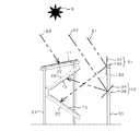
導光装置3は、図3に示すように、2段目の太陽電池パネル12に対して太陽光S1を導く第1導光装置31と、3段目の太陽電池パネル13に対して太陽光S2を導く第2導光装置32と、を備えている。これら、第1導光装置31と第2導光装置32は、太陽電池パネル1を挟んでその前後に配置されている。1段目の太陽電池パネル11に直接照射される太陽光を、太陽光S3とする。なお、この実施形態1において、太陽電池パネル1が太陽S側へ傾斜している方向を前方側と定義したとき、第1導光装置31は、太陽電池パネル1の後方側に配置されている。
As shown in FIG. 3, the
第1導光装置31及び第2導光装置32は、それぞれ複数の支持材33によりほぼ水平に支持されている。この実施形態1では、第1導光装31の方が第2導光装置32よりも高い位置に設置されている。
The first
第1導光装置31は、太陽光S1を反射させてその反射光を太陽電池パネル11へ導く反射板34と、反射板34の角度調整手段35と、を備えている。反射板34には、太陽光の反射率が高い反射用鏡面を有し、かつそれ自体耐久性に優れたものであれば、金属製や樹脂製、ガラス製に限らず種々の反射板を適用することができる。
The first
角度調整手段35としては、手動調整式や自動調整式、あるいはそれらを組み合わせたものを採用することができる。この実施形態では、図2に示すように、手動調整用のハンドル36と、自動調整用の駆動モータ37とを備えたものを例示してある。
As the angle adjustment means 35, a manual adjustment type, an automatic adjustment type, or a combination thereof can be adopted. In this embodiment, as shown in FIG. 2, an example provided with a
具体的には、反射板34は、図1に示すように、2段目の太陽電池パネル12の長手方向に沿って長い矩形(長方形)に形成されると共に、反射板34の傾斜角度調整用の水平軸38を有している。そして、反射板34はこの水平軸38を中心にして回動することで、太陽光S1を太陽電池パネル12に導く角度を微調整可能に構成されている。
Specifically, as shown in FIG. 1, the reflecting
第2導光装置32は、第1導光装置31と同様に、手動調整用のハンドル36と、自動調整用の駆動モータ37とを備えている。反射板34は、3段目の太陽電池パネル13の長手方向に沿って長い矩形(長方形)に形成されると共に、反射板34の傾斜角度調整用の水平軸38を有している。そして、反射板34はこの水平軸38を中心にして回動することで、太陽光S2を太陽電池パネル13に導く角度を微調整可能に構成されている。
Similar to the first
なお、特に図示していないが、太陽Sの高さに応じて駆動モータ37の回転制御を行うように予めプログラムした制御手段を装備する構成としてもよい。
Although not particularly shown in the figure, a control means programmed in advance so as to perform rotation control of the
本実施形態によれば、太陽電池パネル1を上下に間隔をおいて3段に配置することで、敷地や空き地あるいは平屋根等の単位面積当たりの有効利用を図ることができる。また、2段目の太陽電池パネル12及び3段目の太陽電池パネル13に対して太陽光を導く第1導光装置31及び第2導光装置32を装備することにより、多段に配置することで日陰になる太陽電池パネル12、13に太陽光を照射することができる。これにより太陽電池パネルを設置する敷地の単位面積あたりの発電量を格段に向上させることができる。したがって、狭い敷地や平屋根等の上でも、従来よりも大きな発電量を得ることができる。
According to this embodiment, the
また、導光装置を、上から二段目以降の太陽電池パネル12、13に対して太陽光S1、S2を導く構成とすることで、上から1段目が日陰にならない場合にはそれを除き、日陰になり易い2段目以降の太陽電池パネルにのみ、太陽光を導くことができる。これにより、1段目の太陽電池パネル11を通常の使用形態とすることができる。
Moreover, when the light guide device is configured to guide sunlight S1 and S2 to the
また、上から1段目の太陽電池パネル11を、その表面が太陽側へ向く形態で傾斜させ、2段目以降の太陽電池パネル12、13も導光装置で導かれる太陽光と向き合う形態となるように傾斜させることで、各段の太陽電池パネルのそれぞれが太陽光発電に適した傾斜状態とすることができる。これにより太陽電池パネル全体の発電効率を高めることが可能になる。
In addition, the first-stage solar cell panel 11 from the top is inclined so that the surface thereof faces the sun side, and the second-stage and subsequent
また、2段目の太陽電池パネル12に太陽光S1を導く第1導光装置31と、3段目の太陽電池パネル13に太陽光S2を導く第2導光装置32とを設けることで、各段専用の導光装置を配置することができる。これにより各段の太陽電池パネルに太陽光を効率的に導く構成とすることが可能になる。
Moreover, by providing the 1st
また、第1導光装置31と第2導光装置32を、太陽電池パネル1を間に挟む形態でその両側(太陽に向かって前側と後側)に配置することで、太陽光の採光及び導光において、第1導光装置31と第2導光装置32とが互いに邪魔にならないように配置することができる。これにより、多段の太陽電池パネルに対して太陽光を確実かつ効率的に導くことができる。
Further, by arranging the first
さらに、導光装置3が、反射板34とその反射板34の角度調整手段35とを備えている構成としたことで、太陽電池パネルの発電効率を十分に高めることができるように、太陽光の導光状態を効率的にかつ有効に制御することができる。
Furthermore, since the
(実施形態2)
図4は、本発明の実施形態2に係る太陽光発電装置10の概略側面図である。同図において、先の実施形態1と同一の構成要素については同一の符号を付してその説明を簡略化する。
(Embodiment 2)
FIG. 4 is a schematic side view of the photovoltaic
この実施形態2では、第1導光装置31と第2導光装置32を、太陽電池パネル1の片側に、上下2段に配置した構造としたものである。この場合、第1導光装置31を上段に、第2導光装置32を下段に配置し、かつ、第1導光装置31を第2導光装置32よりも外側(太陽に向かって後側)に配置してある。導光装置をこのように構成した場合、第1導光装置31と第2導光装置32を一か所にまとめてコンパクトな配置とすることができる。また、支持材33を兼用することもできる。
In the second embodiment, the first
(実施形態3)
図5は、本発明の実施形態3に係る太陽光発電装置10の概略側面図である。同図において、先の実施形態と同一の構成要素については同一の符号を付してその説明を簡略化する。
(Embodiment 3)
FIG. 5 is a schematic side view of the photovoltaic
この実施形態3では、第1導光装置31と第2導光装置32を、太陽電池パネル1の片側(太陽に向かって後側)に、上下2段に配置すると共に、2段目の太陽電池パネル12と3段目の太陽電池パネル13の向きと傾斜状態にも工夫した構造としたものである。この場合、第1導光装置31を上段に、第2導光装置32を下段に配置し、かつ、第1導光装置31を第2導光装置32の直上に配置してある。
In the third embodiment, the first
また、2段目の太陽電池パネル12は第2導光装置32の反射板34からの反射光を受けるように傾斜角度を変えて下向きに配置してある。3段目の太陽電池パネル13は第1導光装置31の反射板34からの反射光を受けるように傾斜角度を変えて上向きに配置してある。
Further, the second-stage
導光装置をこのように構成した場合も、第1導光装置31と第2導光装置32を一か所にまとめてコンパクトな配置とすることができる。また、支柱33を兼用することもできる。さらに、反射板34による太陽光S1の反射光に対してほぼ直角に近い形で太陽電池パネル13を向き合わせることができる。また、反射板34による太陽光S2の反射光に対してほぼ直角に近い形で太陽電池パネル12を向き合わせることができる。これにより、発電効率を高めることができる。
Even when the light guide device is configured in this way, the first
(実施形態4)
図6は、本発明の実施形態4に係る太陽光発電装置10の概略側面図である。同図において、先の実施形態と同一の構成要素については同一の符号を付してその説明を簡略化する。
(Embodiment 4)
FIG. 6 is a schematic side view of the solar
この実施形態4では、太陽電池パネルを2段に配置すると共に、2段目の太陽電池パネル12をほぼ鉛直に配置した例を示している。この場合、第1導光装置31を、太陽電池パネル1よりも外側(太陽に向かって後側)に配置している。したがって、2段目の太陽電池パネル12は第1導光装置31の反射板34と向き合う形態で、支持材22に支持されている。なお、この実施形態での支持材22は、支柱のようにほぼ鉛直に設けられている。
The fourth embodiment shows an example in which the solar cell panels are arranged in two stages and the second-stage
太陽光発電装置10をこのように構成した場合、1段目の太陽電池パネル11の下に、2段目の太陽電池パネル12を収納する形態で配置できる。また、反射板34による太陽光S1の反射光に対してほぼ直角に太陽電池パネル12を向き合わせることができる。さらに、1段目の太陽電池パネル11の配置高さを高くすることで、2段目の太陽電池パネル12の上下の高さをより高くして、大きな面積の太陽電池パネル12を配置することが可能になる。
When the solar
なお、前記各実施形態において示した各太陽電池パネルの段数や傾斜状態、導光装置の構造や配置位置等は一例であって、設計要求等に基づき種々変更可能である。例えば、図3において、2段目の太陽電池パネル12と3段目の太陽電池パネル13とを、図6に示すようにほぼ鉛直に配置すると共に、太陽電池パネル面を互いに外向きに配置して、それぞれの反射板34からの反射光を受光させる構成としても良い。
Note that the number and inclination of each solar cell panel, the structure and arrangement position of the light guide device, and the like shown in each embodiment are merely examples, and can be variously changed based on design requirements and the like. For example, in FIG. 3, the second-stage
1 太陽電池パネル
11 1段目の太陽電池パネル
12 2段目の太陽電池パネル
13 3段目の太陽電池パネル
2 基台
21 支柱
22 支持材
3 導光装置
31 第1導光装置
32 第2導光装置
34 反射板
35 角度調整手段
DESCRIPTION OF
Claims (1)
太陽光を反射板により反射させて太陽電池パネルに導く導光装置と、を備え、
前記3段の太陽電池パネルのそれぞれが太陽側へ向く形態となるように傾斜しており、
前記導光装置は、2段目の太陽電池パネルに太陽光を導く第1導光装置と、3段目の太陽電池パネルに太陽光を導く第2導光装置とを有し、
前記第1導光装置と第2導光装置は、太陽電池パネルを間に挟む形態で太陽に向かって前側と後側にそれぞれ配置され、
前記第2導光装置は前記第1導光装置よりも低い位置に配置され、
前記各導光装置には前記反射板の角度調整手段が設けられていることを特徴とする太陽光発電装置。 Solar cell panels arranged in three stages at intervals above and below,
A light guide device that reflects sunlight by a reflector and guides it to a solar cell panel ,
Each of the three-stage solar cell panels is inclined so as to face the solar side,
The light guide device includes a first light guide device that guides sunlight to the second-stage solar cell panel, and a second light guide device that guides sunlight to the third-stage solar cell panel,
The first light guide device and the second light guide device are respectively arranged on the front side and the rear side toward the sun in a form sandwiching the solar cell panel therebetween,
The second light guide device is disposed at a position lower than the first light guide device;
Each of the light guide devices is provided with an angle adjusting means for the reflecting plate .
Priority Applications (1)
| Application Number | Priority Date | Filing Date | Title |
|---|---|---|---|
| JP2011244154A JP5704342B2 (en) | 2011-11-08 | 2011-11-08 | Solar power plant |
Applications Claiming Priority (1)
| Application Number | Priority Date | Filing Date | Title |
|---|---|---|---|
| JP2011244154A JP5704342B2 (en) | 2011-11-08 | 2011-11-08 | Solar power plant |
Publications (2)
| Publication Number | Publication Date |
|---|---|
| JP2013102012A JP2013102012A (en) | 2013-05-23 |
| JP5704342B2 true JP5704342B2 (en) | 2015-04-22 |
Family
ID=48622379
Family Applications (1)
| Application Number | Title | Priority Date | Filing Date |
|---|---|---|---|
| JP2011244154A Active JP5704342B2 (en) | 2011-11-08 | 2011-11-08 | Solar power plant |
Country Status (1)
| Country | Link |
|---|---|
| JP (1) | JP5704342B2 (en) |
Cited By (1)
| Publication number | Priority date | Publication date | Assignee | Title |
|---|---|---|---|---|
| CN105119559A (en) * | 2015-08-31 | 2015-12-02 | 北京视域四维城市导向系统规划设计有限公司 | Automatic sensing adjustment solar power collection device |
Families Citing this family (4)
| Publication number | Priority date | Publication date | Assignee | Title |
|---|---|---|---|---|
| CN103956960A (en) * | 2014-05-15 | 2014-07-30 | 无锡同春新能源科技有限公司 | Solar photovoltaic power station increasing generating capacity through sun tracing energy-saving reflection boards |
| JP6875780B2 (en) * | 2019-07-23 | 2021-05-26 | 哲弥 佐野 | Multi-story solar power generation unit that combines a storage room and a reflector |
| WO2023073962A1 (en) * | 2021-10-29 | 2023-05-04 | 国際先端技術総合研究所株式会社 | Photovoltaic apparatus |
| CN114421591B (en) * | 2022-01-12 | 2022-09-13 | 深圳市华源宏新材料有限公司 | Battery storage device with solar power storage assembly for medical instrument and method |
Family Cites Families (7)
| Publication number | Priority date | Publication date | Assignee | Title |
|---|---|---|---|---|
| JPH054524U (en) * | 1991-07-03 | 1993-01-22 | シヤープ株式会社 | Solar cell module |
| JPH0593055U (en) * | 1992-05-15 | 1993-12-17 | ティーディーケイ株式会社 | Solar power generator |
| JPH0745854A (en) * | 1993-07-30 | 1995-02-14 | Maeda Corp | Solar power generation device |
| JPH0714660U (en) * | 1993-08-19 | 1995-03-10 | 三菱重工業株式会社 | Centralized solar panel device |
| CN101419992B (en) * | 2007-10-22 | 2011-03-23 | 鸿富锦精密工业(深圳)有限公司 | Solar cell construction |
| JP2013518397A (en) * | 2010-01-29 | 2013-05-20 | シンベント エーエス | Daylighting window system with solar cells |
| JP2011176251A (en) * | 2010-02-24 | 2011-09-08 | Minoru Iwabuchi | Installation method of multistage solar cell panel with inclined reflector |
-
2011
- 2011-11-08 JP JP2011244154A patent/JP5704342B2/en active Active
Cited By (1)
| Publication number | Priority date | Publication date | Assignee | Title |
|---|---|---|---|---|
| CN105119559A (en) * | 2015-08-31 | 2015-12-02 | 北京视域四维城市导向系统规划设计有限公司 | Automatic sensing adjustment solar power collection device |
Also Published As
| Publication number | Publication date |
|---|---|
| JP2013102012A (en) | 2013-05-23 |
Similar Documents
| Publication | Publication Date | Title |
|---|---|---|
| US9362863B2 (en) | Building body with solar tracking device | |
| US10062796B2 (en) | Photovoltaic system, module holder system and reflector | |
| JP5704342B2 (en) | Solar power plant | |
| JP5799156B1 (en) | Solar glass house and solar glass house complex | |
| US10156383B2 (en) | System of secondary reflectors with high level of efficiency for storage and use of energy from a solar source | |
| JP2016163522A (en) | Angle variable photovoltaic power generation system | |
| KR101175662B1 (en) | Sun location tracking type solar generation apparatus | |
| KR20100025208A (en) | Solar tracking device | |
| KR101968936B1 (en) | Multi Stack PV System with Reflector | |
| JP2014009569A (en) | Trestle for installing solar cell module | |
| KR20190076663A (en) | Module for solar energy generation and apparatus having the same | |
| KR101622764B1 (en) | solar-cell module support structure | |
| JP3174073U (en) | Solar power plant | |
| CN111106195A (en) | Assembled angle-adjustable folding plate-shaped photovoltaic module and photovoltaic system thereof | |
| JP5302841B2 (en) | Louver device | |
| EP2626649B1 (en) | Screens with arranged solar modules and independently controlled intermediate screens | |
| US20120167493A1 (en) | Sunlight-collecting apparatus | |
| KR101968937B1 (en) | Pyramid Solar PV Structure | |
| KR20210110391A (en) | Stacked photovoltaic power generation system with reflector applied | |
| KR100764099B1 (en) | A structure of sun-ray collecting board with reflector and the method of manufacturing sun-ray collecting board thereof | |
| JP2014103381A (en) | Photovoltaic power generation device | |
| KR102112347B1 (en) | Prefabricated Solar Structure | |
| JP2010192777A (en) | Photovoltaic power generation facility and installation method of solar cell array | |
| JP3204348U (en) | Solar power panel | |
| JP2015228729A (en) | Solar panel site |
Legal Events
| Date | Code | Title | Description |
|---|---|---|---|
| A621 | Written request for application examination |
Free format text: JAPANESE INTERMEDIATE CODE: A621 Effective date: 20140418 |
|
| A131 | Notification of reasons for refusal |
Free format text: JAPANESE INTERMEDIATE CODE: A131 Effective date: 20140729 |
|
| A977 | Report on retrieval |
Free format text: JAPANESE INTERMEDIATE CODE: A971007 Effective date: 20140730 |
|
| A521 | Request for written amendment filed |
Free format text: JAPANESE INTERMEDIATE CODE: A523 Effective date: 20140929 |
|
| TRDD | Decision of grant or rejection written | ||
| A01 | Written decision to grant a patent or to grant a registration (utility model) |
Free format text: JAPANESE INTERMEDIATE CODE: A01 Effective date: 20150203 |
|
| A61 | First payment of annual fees (during grant procedure) |
Free format text: JAPANESE INTERMEDIATE CODE: A61 Effective date: 20150210 |
|
| R150 | Certificate of patent or registration of utility model |
Ref document number: 5704342 Country of ref document: JP Free format text: JAPANESE INTERMEDIATE CODE: R150 |
|
| R250 | Receipt of annual fees |
Free format text: JAPANESE INTERMEDIATE CODE: R250 |
|
| S201 | Request for registration of exclusive licence |
Free format text: JAPANESE INTERMEDIATE CODE: R314201 |
|
| R350 | Written notification of registration of transfer |
Free format text: JAPANESE INTERMEDIATE CODE: R350 |