JP5703303B2 - RF configuration self-discovery for wireless systems - Google Patents
RF configuration self-discovery for wireless systems Download PDFInfo
- Publication number
- JP5703303B2 JP5703303B2 JP2012533283A JP2012533283A JP5703303B2 JP 5703303 B2 JP5703303 B2 JP 5703303B2 JP 2012533283 A JP2012533283 A JP 2012533283A JP 2012533283 A JP2012533283 A JP 2012533283A JP 5703303 B2 JP5703303 B2 JP 5703303B2
- Authority
- JP
- Japan
- Prior art keywords
- component
- signal
- distribution system
- components
- receiver
- Prior art date
- Legal status (The legal status is an assumption and is not a legal conclusion. Google has not performed a legal analysis and makes no representation as to the accuracy of the status listed.)
- Active
Links
- 238000000034 method Methods 0.000 claims description 22
- 238000001228 spectrum Methods 0.000 claims description 7
- 230000008569 process Effects 0.000 claims description 6
- 230000004044 response Effects 0.000 claims description 2
- 230000003595 spectral effect Effects 0.000 claims 2
- 101710162453 Replication factor A Proteins 0.000 claims 1
- 102100035729 Replication protein A 70 kDa DNA-binding subunit Human genes 0.000 claims 1
- 238000010586 diagram Methods 0.000 description 4
- 238000011144 upstream manufacturing Methods 0.000 description 4
- 230000008859 change Effects 0.000 description 3
- 238000001514 detection method Methods 0.000 description 2
- 238000004458 analytical method Methods 0.000 description 1
- 238000003491 array Methods 0.000 description 1
- 238000004891 communication Methods 0.000 description 1
- 239000002131 composite material Substances 0.000 description 1
- 230000009977 dual effect Effects 0.000 description 1
- 238000005516 engineering process Methods 0.000 description 1
- 230000006870 function Effects 0.000 description 1
- 239000004615 ingredient Substances 0.000 description 1
- 238000002955 isolation Methods 0.000 description 1
- 230000003287 optical effect Effects 0.000 description 1
- 230000007704 transition Effects 0.000 description 1
Images


Classifications
-
- H—ELECTRICITY
- H04—ELECTRIC COMMUNICATION TECHNIQUE
- H04L—TRANSMISSION OF DIGITAL INFORMATION, e.g. TELEGRAPHIC COMMUNICATION
- H04L65/00—Network arrangements, protocols or services for supporting real-time applications in data packet communication
-
- H—ELECTRICITY
- H04—ELECTRIC COMMUNICATION TECHNIQUE
- H04B—TRANSMISSION
- H04B1/00—Details of transmission systems, not covered by a single one of groups H04B3/00 - H04B13/00; Details of transmission systems not characterised by the medium used for transmission
- H04B1/06—Receivers
- H04B1/16—Circuits
- H04B1/20—Circuits for coupling gramophone pick-up, recorder output, or microphone to receiver
- H04B1/205—Circuits for coupling gramophone pick-up, recorder output, or microphone to receiver with control bus for exchanging commands between units
-
- H—ELECTRICITY
- H04—ELECTRIC COMMUNICATION TECHNIQUE
- H04L—TRANSMISSION OF DIGITAL INFORMATION, e.g. TELEGRAPHIC COMMUNICATION
- H04L61/00—Network arrangements, protocols or services for addressing or naming
-
- H—ELECTRICITY
- H04—ELECTRIC COMMUNICATION TECHNIQUE
- H04L—TRANSMISSION OF DIGITAL INFORMATION, e.g. TELEGRAPHIC COMMUNICATION
- H04L2101/00—Indexing scheme associated with group H04L61/00
- H04L2101/60—Types of network addresses
- H04L2101/618—Details of network addresses
- H04L2101/622—Layer-2 addresses, e.g. medium access control [MAC] addresses
-
- H—ELECTRICITY
- H04—ELECTRIC COMMUNICATION TECHNIQUE
- H04R—LOUDSPEAKERS, MICROPHONES, GRAMOPHONE PICK-UPS OR LIKE ACOUSTIC ELECTROMECHANICAL TRANSDUCERS; DEAF-AID SETS; PUBLIC ADDRESS SYSTEMS
- H04R2410/00—Microphones
-
- H—ELECTRICITY
- H04—ELECTRIC COMMUNICATION TECHNIQUE
- H04R—LOUDSPEAKERS, MICROPHONES, GRAMOPHONE PICK-UPS OR LIKE ACOUSTIC ELECTROMECHANICAL TRANSDUCERS; DEAF-AID SETS; PUBLIC ADDRESS SYSTEMS
- H04R2420/00—Details of connection covered by H04R, not provided for in its groups
- H04R2420/07—Applications of wireless loudspeakers or wireless microphones
Description
本出願は、2009年10月7日に申請された米国仮特許出願番号第61/249、438号、および2009年11月25日に申請された米国特許出願番号第12/626、105号の利益を主張する。 This application is based on US Provisional Patent Application No. 61 / 249,438, filed October 7, 2009, and US Patent Application No. 12 / 626,105, filed November 25, 2009. Insist on profit .
無線マイクロホンレシーバは、しばしば同軸アンテナ分配システムに接続されている。レシーバは、典型的には、分配増幅器に接続され、および一本の同軸ケーブルを介してお互いにカスケード接続されている。レシーバに割り当てられる周波数範囲は、イーサネット(登録商標)などのネットワーク・プロトコルを介して制御することができる。分配増幅器および関連するレシーバが異なるフィルター周波数帯で構成されると、ミスマッチによって、システム性能が劣化し、または、動作しなくなる。その上、コンポーネントが適切に接続されていないと、分配システムは適切に動作できない。 Wireless microphone receivers are often connected to a coaxial antenna distribution system. The receivers are typically connected to a distribution amplifier and cascaded to each other via a single coaxial cable. The frequency range assigned to the receiver can be controlled via a network protocol such as Ethernet. If the distribution amplifier and the associated receiver are configured with different filter frequency bands, mismatch will cause system performance to degrade or become inoperable. In addition, the distribution system cannot operate properly if the components are not properly connected.
米国特許出願公開第2003/0157916号は、RF分配システムの第1の無線周波数(RF)コンポーネントに、生成信号を提供するように命令する工程を含む。本発明は、この開示に加えて、さらに、前記信号が検出された場合に、第2のRFコンポーネントから情報を受信する工程であって、前記情報は、第1のRFコンポーネントと前記第2のRFコンポーネントとが電気的に接続されたことを示す情報である工程と;前記RF分配システムの残りのRFコンポーネントに対して、前記命令する工程と;前記受信する工程を繰り返す工程と、前記命令する工程、前記受信する工程、および前記繰り返す工程に基づいて、前記RF分配システムのRF構成を決定する工程を含む。 U.S. Patent Application Publication No. 2003/0157916 includes instructing a first radio frequency (RF) component of an RF distribution system to provide a generated signal. In addition to this disclosure, the present invention further comprises receiving information from a second RF component when the signal is detected, the information comprising the first RF component and the second RF component. Information indicating that the RF component is electrically connected; instructing the remaining RF components of the RF distribution system; repeating the receiving step; Determining an RF configuration of the RF distribution system based on a step, the receiving step, and the repeating step.
本発明の別の実施形態によれば、装置は、第1の無線周波数(RF)コンポーネントと、第2のRFコンポーネントと、少なくとも一つのプロセッサ−と、機械で実行可能な命令を記憶するメモリであって、前記命令が実行されると、装置を、RF分配システムの第1のRFコンポーネントに信号を生成するように命令する工程と、前記第2のRFコンポーネントで、前記信号が検出されると、前記第2のRFコンポーネントから、前記第1のRFコンポーネントと前記第2のRFコンポーネントが電気的に接続されたことを示す情報を受信する工程と、前記RF分配システムの残りのRFコンポーネントに対して、前記命令する工程と、前記受信する工程とを繰り返す工程と、前記命令する工程、前記受信する工程、および前記繰り返す工程に基づいて、前記RF分配システムのRF構成を決定する工程として動作させるメモリとを含む。 According to another embodiment of the present invention, an apparatus includes a first radio frequency (RF) component, a second RF component, at least one processor, and a memory that stores machine-executable instructions. And when the command is executed, commands the device to generate a signal to a first RF component of the RF distribution system; and when the signal is detected at the second RF component. Receiving information from the second RF component indicating that the first RF component and the second RF component are electrically connected; and for the remaining RF components of the RF distribution system Repeating the commanding step and the receiving step, the commanding step, the receiving step, and the repeating step. Based on, and a memory to operate as a step of determining the RF configuration of the RF distribution system.
本発明の別の実施形態によれば、RF分配システム(例えば、ワイアレス マイクロホンレシーバ、スキャナ、アンテナ分配システム、または、本明細書に記載のコンポーネントの一部または全部を含むすべてのシステム)は、その構成を決定し、および決定された構成の一貫性を検証する。分配システムの第1のRFコンポーネントは、第1のポートの信号を変調する。第2のRFコンポーネントが、第2のポートで変調された信号を検出すると、次に、プロセッサ−は、2つのRFコンポーネントが一緒に接続されていると判断する。プロセッサ−によって構成が決定されると、RF分配は、構成に一貫性があるか否かを検証する(例えば、接続されたコンポーネントが同一周波数帯で動作するか否か、および、すべてのコンポーネントが少なくとも一つの他のコンポーネントに接続されているか否か)。 According to another embodiment of the present invention, an RF distribution system (eg, a wireless microphone receiver, scanner, antenna distribution system, or any system that includes some or all of the components described herein) Determine the configuration and verify the consistency of the determined configuration. The first RF component of the distribution system modulates the signal at the first port. If the second RF component detects a signal modulated at the second port, then the processor determines that the two RF components are connected together. Once the configuration is determined by the processor, the RF distribution verifies whether the configuration is consistent (eg, whether connected components operate in the same frequency band, and all components are Whether it is connected to at least one other component).
本発明の別の実施形態によれば、第1のRFコンポーネントは、DC電圧レベルを変更すること、またはトーンに基づいて生成信号を変調できる。 According to another embodiment of the present invention, the first RF component can change the DC voltage level or modulate the generated signal based on the tone.
本発明の別の実施形態によれば、それぞれのRFコンポーネントのデバイス識別子に基づいて、RF分配システムは、それぞれのRFコンポーネントに、別々に、生成信号を提供するように命令することができる。デバイス識別子は、イーサネット(登録商標)、USB、およびZigbee(登録商標)を含むサポートされたプロトコルによって支持される、デバイスアドレスから得ることができる。 According to another embodiment of the present invention , based on the device identifier of each RF component, the RF distribution system can instruct each RF component to provide a generated signal separately. The device identifier can be obtained from a device address supported by supported protocols including Ethernet, USB, and Zigbee.
本発明の別の実施形態によれば、決定されたRF構成は、一貫した動作を検証することができる。例えば、接続されたRFコンポーネントの周波数帯の一貫性を検証し、RF分配システムのそれぞれのRFコンポーネントが、別のコンポーネントに接続されていることを検証し、および、RFコンポーネントがRF構成の末端でない場合には、それぞれのRFコンポーネントが、先行するRFコンポーネント、および後続するRFコンポーネントに接続されていることを検証できる。 According to another embodiment of the invention, the determined RF configuration can verify consistent operation. For example, verify the consistency of the frequency bands of the connected RF components, verify that each RF component of the RF distribution system is connected to another component, and the RF component is not the end of the RF configuration In some cases, it can be verified that each RF component is connected to a preceding RF component and a subsequent RF component.
本発明の別の実施形態によれば、RF分配システムは、RFスペクトルをスキャンし、スキャンに基づいてRF分配システムにとって互換性のあるRFを提供する、一組の周波数を決定し、一組の周波数に対応するRFコンポーネントを構成する。 According to another embodiment of the present invention, the RF distribution system scans the RF spectrum, determines a set of frequencies based on the scan and provides a compatible RF for the RF distribution system, The RF component corresponding to the frequency is configured.
同様の参照番号が同様の特徴を示す、添付の図面を考慮して、以下の記載を参照することによって、本発明の例示的な実施形態および利点をより完全に理解することができる。 A more complete understanding of the exemplary embodiments and advantages of the present invention may be gained by reference to the following description, taken in conjunction with the accompanying drawings, in which like reference numerals indicate like features.
多様な例示的な実施形態の以下の記述では、実施形態の一部を形成し、および、本発明を実施することができる、種々の実施形態を説明するために示される添付図面について説明する。本発明の範囲から逸脱しない範囲で、他の実施形態を利用することができ、並びに、構造的な変更および機能的な変更を実施することができることが理解されるべきである。 In the following description of various exemplary embodiments, reference is made to the accompanying drawings that form a part hereof, and in which are shown by way of illustration various embodiments in which the invention may be practiced. It should be understood that other embodiments may be utilized and structural and functional changes may be made without departing from the scope of the present invention.
本発明の態様は、無線周波数(RF)分配システム(例えば、ワイアレス マイクロホンレシーバ、スキャナ、アンテナ分配システム、または、本明細書に記載のコンポーネントの一部または全部を含むすべてのシステム)の構成を決定し、および決定された構成の一貫性を検証することに関する。分配システムの第1のRFコンポーネントは、第1のポートの信号を変調する。第2のRFコンポーネントが、第2のポートで変調された信号を検出すると、次に、プロセッサ−は、2つのRFコンポーネントが一緒に接続されていると判断する。プロセッサ−によって構成が決定されると、プロセッサ−は、該構成に一貫性があるか否かを検証できる(例えば、接続されたコンポーネントが同一周波数帯で動作するか否か、および、すべてのコンポーネントが少なくとも他のコンポーネントに接続されているか否か)。 Aspects of the invention determine the configuration of a radio frequency (RF) distribution system (eg, a wireless microphone receiver, a scanner, an antenna distribution system, or any system that includes some or all of the components described herein). And verifying the consistency of the determined configuration. The first RF component of the distribution system modulates the signal at the first port. If the second RF component detects a signal modulated at the second port, then the processor determines that the two RF components are connected together. Once the configuration is determined by the processor, the processor can verify whether the configuration is consistent (eg, whether connected components operate in the same frequency band and all components). Is at least connected to other components).
図1は、本発明の例示的な実施形態による、ワイアレスシステムを支持するための装置を示す。マイクロホンレシーバ105、107、109、および111は、同軸アンテナ分配システム中で、分配増幅器103を介してアンテナ102に接続される。レシーバ105、107、109、および111、並びに、分配増幅器103は、例えば、イーサネット等のネットワーク・プロトコルを介して、それぞれが、イーサネット接続153、イーサネット接続155、イーサネット接続157、イーサネット接続159、およびイーサネット接続151されたプロセッサ−101によって制御できる。図1では、それぞれが分かれたイーサネット接続を示すが、接続されたデバイス、および、それぞれのデバイスに割り当てられた固有のアドレスによってイーサネット接続が得られる、デイジーチェーン構成を介して、イーサネットの接続性が支持される。
FIG. 1 illustrates an apparatus for supporting a wireless system, according to an illustrative embodiment of the invention.
分配増幅器103、並びに、関連するレシーバ105、107、109、および111が異なる周波数範囲または周波数帯(「周波数帯」と称する)で構成されると、ミスマッチによって、システム性能が劣化し、または、動作しなくなる。レシーバ105、107、109、および111のアンテナポート(例えば、レシーバ105の入力RFポート171)、および、ライン増幅器およびパワーアンテナを駆動するために使用される分配増幅器103に、電圧源が存在する。プロセッサ−101によって発行された、イーサネット接続を介した特定のレシーバへの、所定のネットワークシステムコマンドによって、DC電圧は、変調するために使用できる(例えば、ON/OFFまたは複数の電圧レベル)。実施形態では、DC電圧は、動作電圧レベル(例えば、12ボルト)と中間電圧レベル(例えば、10.5ボルトまたは13.5ボルト)間で、信号のDC成分を変化させることで変調される。変調されたDC電圧は、アップストリ−ムレシーバによって検出できる(例えば、レシーバ107がレシーバ107の入力RFポートで信号を変調しているのであれば、出力RFポート173で)、および、これらのRFコンポーネント間のRFリンク(例えば、RF接続160、161、162、163または165)が決定された(発見された)ことを、システムプロセッサ−101に通知する、検出レシーバによって、メッセージをイーサネットネットワーク上に送出できる。RFコンポーネントが異なる周波数帯に同調され、および一緒に接続されている場合には、RF分配システム100は、表示デバイス115に指示情報を表示できるシステムソフトウェアによって、ユーザにミスマッチを通知できる。
If the distribution amplifier 103 and the
他の実施形態は、異なった方法で、入力RFポート171の信号を変調できる。例えば、信号は、一つ以上のトーンまたはシリアル/デュプレックスデータストリームで変調できる。
Other embodiments can modulate the signal at the
いくつかの実施形態では、シンプレックス/デュプレックス、デジタルデータストリーム(例えば、UARTによって)、低速シンプレックスデータストリーム、または単一パルス識別子(例えば、単一の識別ビットだけを有するフォーマットされていないデータ)を使用して、ポート171で信号の情報を送出できる。
Some embodiments use simplex / duplex, digital data stream (eg, via UART), slow simplex data stream, or single pulse identifier (eg, unformatted data with only a single identification bit) Thus, the signal information can be transmitted from the
図1に示された実施形態では、レシーバ(例えば、レシーバ105)は、入力RFポート(例えば、ポート171)の信号を変調するので、RFリンクを介して、コンポーネントが一緒に接続されている場合に、先行する(アップストリ−ム)RFコンポーネント(レシーバまたは分配増幅器、例えば、増幅器103)が変調された信号を検出する。しかしながら、他の実施形態では、RFコンポーネントは、出力RFポート(例えば、ポート173)を変調できるので、次の(ダウンストリーム)RFコンポーネント(例えば、レシーバ107)は、その入力RFポートで変調された信号を検出できる。 In the embodiment shown in FIG. 1, the receiver (eg, receiver 105) modulates the signal at the input RF port (eg, port 171) so that the components are connected together via an RF link. The preceding (upstream) RF component (receiver or distribution amplifier, eg, amplifier 103) detects the modulated signal. However, in other embodiments, the RF component can modulate the output RF port (eg, port 173) so that the next (downstream) RF component (eg, receiver 107) was modulated at its input RF port. The signal can be detected.
RF分配システム100は、自動的に、同一周波数帯に動作周波数を割り当てることで、レシーバ103、レシーバ105、レシーバ107、およびレシーバ109を構成することもできる。構成手続きは、スキャナ117によって周波数帯(単数または複数)をスキャンし、および最も良好なRF互換性を提供する一組の周波数を決定した後に、実施できる。スキャナ117は、RFリンク162を介して、分配増幅器103からRFスペクトルをアクセスし、および、スペクトルに関する情報をプロセッサ−101へイーサネット接続158を介して提供する。一緒にカスケード接続されるレシーバ(例えば、レシーバ105および107)は、次に同一周波数帯で構成され、および、その周波数帯内に個々のチャンネルがプログラムされる。システムセットアップは、ユーザには、システム構成を決定し、明瞭な周波数をスキャンし、周波数帯内の互換周波数を演算し、および、演算された周波数(チャンネル)にレシーバを構成する、単一の動作のように思われる。
The
システム初期設定時、RFコンポーネントがシステム100に追加される場合、またはシステム100の動作中に、RF分配システム100はRF構成を決定できる。システム100は、ユーザからの入力に応答するように、周期的に(例えば、あらかじめ定められた時間間隔に一度)、または自動的に(例えば、システムが初期化される場合、または、RFコンポーネントがRF分配システム100に追加される場合)構成することができる。
At system initialization, when RF components are added to the
イーサネットネットワークを介して、RFコンポーネントにメッセージを送出することによって、プロセッサ−101は、RFコンポーネントの入力RFポートで、信号を変調するように、RFコンポーネントに命令できる。従って、命令されたRFコンポーネントに接続されているRFコンポーネントは、変調された信号が検出されたことを、プロセッサ−101に通知する、メッセージを、イーサネットネットワークによってプロセッサ−101に送信する。 By sending a message to the RF component over the Ethernet network, the processor-101 can instruct the RF component to modulate the signal at the input RF port of the RF component. Accordingly, the RF component connected to the commanded RF component sends a message over the Ethernet network to the processor-101 notifying the processor-101 that a modulated signal has been detected.
プロセッサ−101は、例えば、メモリ113等のコンピュータ読み取り可能な記憶媒体からコンピュータで実行可能な命令を実行でき、発見プロセス(本明細書に記載のすべてのプロセスまたは何れか)を実施する。いくつかの実施形態では、装置110は、プロセッサ−101およびメモリ113を備えることができる。装置110は、一つ以上の特定用途向け集積回路(ASIC)、複合プログラマブル論理デバイス(CPLD)、フィールドプログラマブルゲートアレ−(FPGA)、または他の集積回路を含むことができる。コンピュータ記録媒体は、コンピュータで読み取り可能な命令、データ構造、プログラムモジュール、または、他のデータなどの情報記憶のための何れかの方法、または技術が実装された、揮発性および不揮発性、可搬性および非可搬性媒体を含むことができる。コンピュータ記録媒体は、これらに限定されるわけではないが、所望の情報を記憶するために使用でき、および、プロセッサ−101がアクセスできる、ランダムアクセスメモリ(RAM)、読み出し専用メモリ(ROM)、電気的消却・プログラム可能型読み出し専用メモリ(EEPROM)、フラッシュメモリまたは他のメモリ技術、CD−ROM、デジタル多用途ディスク(DVD)または他の光ディスク記憶、磁気カセット、磁気テープ、磁気ディスク記憶、または、他の磁気ディスクデバイス、若しくは、何れかの他の媒体を含む。実行可能な命令は、本明細書に記載のすべての、または何れかの方法の工程を実行できる。いくつかの実施形態では、装置110(例えば、ラップトップコンピュータ)は、図1に示すレシーバ、スキャナ、および分配増幅器の外部にあってもよい。他の実施形態では、装置110は、それぞれのデバイス(例えば、レシーバ105および107および/または分配増幅器103)に組み込まれてもよく、外部コンピュータは必ずしも必要とされない。
The processor-101 can execute computer-executable instructions from, for example, a computer-readable storage medium, such as the
装置100または装置100の一部は、本明細書に記載の一つ以上の実施形態に関して記載されている動作を、実施するための命令を有する、一つ以上の特定用途向け集積回路(ASIC)、複合プログラマブル論理デバイス(CPLD)、フィールドプログラマブルゲートアレ−(FPGA)、または他の集積回路として、実装されることができる。前記命令は、機械が読み取り可能な媒体に記憶された、ソフトウェアおよび/またはファームウェア命令であってもよく、並びに/または、一つ以上の集積回路および/または他の回路要素と組み合わせられた一つ以上の集積回路の、一連の論理ゲートおよび/または状態マシン回路として、ハードコード化されてもよい。
The
図2は、本発明の例示的な実施形態によるレシーバ105のブロック図を示す。イーサネット接続153を介して、プロセッサ−201によって命令されると(メッセージ251に対応する)、レシーバ105は、入力RFポート171の信号を変調する。信号を変調するために、電力供給モジュレーションハードウェア201は、電力供給203の電圧レベルを変更する。RFチョーク205は、電力供給203を、RF回路206によって処理されたRF信号成分から分離する。アップストリ−ムレシーバ(図示せず)は、変調された信号を検出する。
FIG. 2 shows a block diagram of the
レシーバ105は、ダウンストリームレシーバ(図示せず)からの変調された信号を、検出するための検出回路を含むこともできる。出力RFポート173を介して、変調された信号を検出するために、検出器209は、変調された信号のDC電圧推移を検出し、および、該発生をプロセッサ−201へイーサネット接続153を介して報告する(メッセージ253に対応)。RFカスケード回路208が、RF信号をダウンストリームレシーバに提供する場合には、RFチョーク207は、検出器209に対してRF分離を提供する。検出器209は、スロープ検出器またはアナログ−デジタルコンバータ(ADC)を含む、異なった形態であってもよい。
The
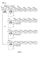
図3は、本発明の例示的な実施形態によるRF分配システム100で、RF構成の自己発見を実施するためのフローチャート300を示す。ブロック301では、プロセス300で、すべてのRF体(例えば、レシ−バ、分配増幅器、およびスキャナ)が試験されたか否かを決定する。もしそうでない場合には、次のRF体が、ブロック303で決定される。いくつかの実施形態では、割り当てられた媒体アクセス制御(MAC)アドレスから、次のRF体が決定される。次のRF体は異なる基準で選択されてもよく、例えば、MACランダムに選択し、または、あらかじめ決定された順番で、MACアドレスを選択してもよい。いくつかの実施形態では、MACアドレスのランダムな選択は、疑似ランダムプロセスによって近似されてもよい。
FIG. 3 shows a
前述のように、MACアドレスの使用によって、デバイス識別子として機能する。しかしながら、他の実施形態では、他の形態のデバイスを特定する識別子を使用することができる。例えば、いくつかの実施形態では、イーサネットとは別の他のプロトコル(例えば、USBまたはZigbee)を支持できる。 As described above, it functions as a device identifier by using the MAC address. However, in other embodiments, identifiers that identify other forms of devices may be used. For example, in some embodiments, other protocols other than Ethernet (eg, USB or Zigbee) can be supported.
ブロック305では、プロセッサ−101は、選択されたRF体に、その入力RFポートで信号を変調するように命令する。ブロック307、ブロック309、およびブロック311では、命令されたRF体が、アンテナ(例えば、アンテナ102)に接続されている分配増幅器(例えば、図1に示すように分配増幅器103)である場合を除いて、アップストリ−ムRF体は、変調された信号を検出し、報告する。さもなければ、いずれのRF体(コンポーネント)も変調された信号を検出しない場合には、構成エラー指示が、プロセッサ−101によって生成される。
At
プロセス300の結果は、RF分配システム100の図形が表示デバイス115(図1に示すように)に表示され、さらなる処理とともに使用できる。図形は、RF体間のハードウェア接続を含むことができ、および、RF構成にエラーがあるか否かを示すこともできる(例えば、異なる周波数帯に対する2つのレシーバが接続されている場合、またはレシーバが分配増幅器または別のレシーバに接続されていない場合)。分析によって、適切なシステム接続の確認を補助し、および、故障したRFケーブルを検出できる。
The result of the
図4は、本発明の例示的な実施形態による、ワイアレスシステムのRF構成400を示す。例示的な実施形態では、周波数帯H、J、K、およびLが、それぞれ、470MHzから518MHz、518MHzから578MHz、578MHzから638MHz、および638MHzから698MHzに対応する。分配増幅器の出力は、4周波数帯の1つ、または、広帯域動作に設定でき、すなわち、出力は470MHzから698MHzの全範囲に及ぶ。図6を参照すると、分配増幅器605に対して示されたフィルター周波数帯A、B、CおよびDは、図4に示すフィルター周波数帯H、J、KおよびLに対応する。分配増幅器401は、すべての周波数帯(470−698MHz)を通過するように構成される。分配増幅器402、分配増幅器414、分配増幅器415、および分配増幅器416(それぞれH−0、J−0、K−0、およびL−0)は、前述のように、470MHz−698MHzのサブ周波数帯に設定される。それぞれのワイアレス マイクロホンレシーバ(例えば、レシーバ404−413)、アンテナ分配増幅器(例えば、増幅器401および402)、およびスキャナ(図5に示すスキャナ503)には、アンテナ入力ポートで、12−15Vの直流信号成分が存在する。DC電圧は、一般にライン増幅器およびパワーアンテナを駆動するために使用される。いくつかの実施形態では、(カスケード)ポートを通過するRFループは、利用可能なDC電圧源を有さない。アンテナポートでのDC電圧は、ネットワークコマンドによってシステムをセットアップ中に、オンおよびオフにトグルされる(動作電圧を変調する)。レシーバがカスケード接続される場合には、レシーバのアンテナポートからのDC電圧は、先行するレシーバのポートを介してループに存在する。ポートを通過するRFループでは、該DCの存在と変調を検出できるので、RF接続チェーン構成を示すことができる。
FIG. 4 shows an
例えば、レシーバ(H−2)405の入力アンテナポートのDCが、オンおよびオフにトグルされると、変調された信号はレシーバ(H−1)404のポートを介してループによって検出され、および、ネットワークに報告される。報告された指示によって、レシーバが405と404間のRF接続461を共有し、および、同一フィルター周波数帯内で動作するように設定されるべきであることがプロセッサ−101に通知される。同様の方法で、ネットワークのそれぞれのレシーバおよび分配増幅器は、ひとつずつ、ポートがトグルされる。別のRF体によって、DCレベル変化が検出されない場合には、トグルされる実体はチェーンのアンテナ端(分配増幅器401に対応)にあるものと推定される。ダイバーシティシステムの場合に、1つのアンテナポートのみによって変化が検出される場合は、RFケーブルが故障、または無いことが検出される。 For example, if the DC of the input antenna port of receiver (H-2) 405 is toggled on and off, the modulated signal is detected by the loop through the port of receiver (H-1) 404, and Reported to the network. The reported indication informs processor-101 that the receiver should share the RF connection 461 between 405 and 404 and be configured to operate within the same filter frequency band. In a similar manner, each receiver and distribution amplifier in the network is toggled on a port one by one. If the DC level change is not detected by another RF body, the entity to be toggled is assumed to be at the antenna end of the chain (corresponding to the distribution amplifier 401). In the case of a diversity system, if a change is detected by only one antenna port, it is detected that the RF cable is faulty or absent.
メッセージは、RF接続の構成を示し、および故障したRFケーブルに関する警告を発行する、コンピュータネットワークによって報告できる。レシーバのRF信号は、チェーンの第1のレシーバによって、該周波数帯にフィルタリングされるので、一緒に接続されたレシーバは、同一の周波数帯に設定されるべきである。分配増幅器の周波数帯が選択される場合には、該分配増幅器によってサービスされるそれぞれのレシーバは、選択された周波数帯の中の周波数に設定されるべきである。分配増幅器(例えば、図4に示す増幅器401)は、広帯域動作にも設定できる(図6の分配増幅器605によって示される周波数帯A、B、C、およびD内のすべての信号を同時に通過させる)。カスケード接続される分配増幅器のそれぞれ(例えば、増幅器402)は、分離された周波数帯に選択され、および4つのレシーバチェーンをサポートし、ここでそれぞれのチェーンは同一の周波数帯である。
The message can be reported by a computer network that indicates the configuration of the RF connection and issues a warning regarding the failed RF cable. Since the RF signal of the receiver is filtered to the frequency band by the first receiver in the chain, the receivers connected together should be set to the same frequency band. If the frequency band of the distribution amplifier is selected, each receiver serviced by the distribution amplifier should be set to a frequency within the selected frequency band. The distribution amplifier (eg,
アンテナ分配増幅器のループスルーも広帯域動作に設定され、広帯域スキャナを支持する(図4には明確に示されないが、図5で議論される)。 The antenna distribution amplifier loop-through is also set to broadband operation and supports a broadband scanner (not explicitly shown in FIG. 4, but discussed in FIG. 5).
いくつかの実施形態では、分配増幅器(例えば、増幅器401および402)はカスケード接続され、RF分配システム100が支持できるレシーバの数を増加させる。いくつかの実施形態では、第2の分配増幅器(例えば、増幅器402)のゲインは、一般にユニティに設定される。
In some embodiments, distribution amplifiers (eg,
図5は、本発明の例示的な実施形態によるワイアレスシステムのRF構成500を示す。構成では、分配増幅器501およびRF接続561を介して、アンテナ504からの入力信号の周波数スペクトルをスキャンするスキャナ503を利用する。分配増幅器501は、フィルタリングされない出力(例えば、出力659に対応)だけではなく、フィルタリングされた出力(例えば、図6に示すように出力651に対応)の両方を出力する。スキャナ503は、接続561を介してフィルタリングされない出力を解析し、および、前述したようにプロセッサ−101に結果を報告する(図1に示すように)。
FIG. 5 shows an
分配増幅器501が分配増幅器502にカスケード接続されると、フィルタリングされた信号(例えば、接続563を介してレシーバ505へ)とフィルタリングされない信号(例えば、接続565を介してレシーバ506へ)を供給する。
When
図6は、本発明の例示的な実施形態による、レシーバユニット607、レシーバユニット609、レシーバユニット611、レシーバユニット613、レシーバユニット615、およびレシーバユニット617に接続されている分配増幅器605のブロック図を示す。分配増幅器605は、アンテナ601およびアンテナ603を介して信号を受信し、および、フィルタリングされたRF出力を、それぞれのレシーバへ提供するので、ダイバーシティ応答を提供する。例えばレシーバユニット607(レシーバ1およびレシーバ2を備える)は、RF接続651およびRF接続653を介して、2つのRF入力信号が提供される。いくつかの実施形態では、レシーバ1およびレシーバ2は、レシーバユニット607の内部でカスケード接続され、同一周波数帯に設定れる。他の実施形態では、レシーバ1およびレシーバ2は同軸ケーブルを介して外部でカスケード接続できる。レシーバユニット609は、RF接続655およびRF接続657を介して、レシーバユニット607にカスケード接続される。さらに、レシーバユニット611が、レシーバユニット609からカスケード接続される。
FIG. 6 shows a block diagram of a
先述したように、分配増幅器605は、接続659および接続661を介して、フィルタリングされないRF信号も提供し、追加のレシーバまたはスキャナをサポートする。
As previously mentioned,
図7は、それぞれが本発明の例示的な実施形態による、分配増幅器ユニット605およびレシーバユニット607のバックパネル701および703を示す。図7は、1つの分配増幅器ユニットおよび1つのレシーバユニットだけを示すが、複数の分配増幅器ユニットおよびレシーバでシステム100を構成してもよく、ユニットが一つ以上のラックで積み重ねられてもよい。例えば、いくつかの例示的な構成では、100を超えるチャンネルをサポートでき、従って50を超えるデュアルチャンネルレシーバユニットを備える。
FIG. 7 shows the
2つのアンテナがバックパネル701のBNCコネクタ713およびBNCコネクタ714に接続でき、RFダイバーシティを提供できる。フィルタリングされたRF出力(BNCコネクタ705と709、BNCコネクタ706と710、BNCコネクタ707と711、およびBNCコネクタ708と712に対応するダイバーシティペアをサポートする)およびフィルタリングされないRF出力(BNCコネクタ715および716に対応)の両方とも、同軸ケーブルを介してレシーバユニットに接続されている。
Two antennas can be connected to the
バックパネル703は2つのレシーバ(チャンネル)に対応し、ここでは、コネクタ721および722を介したデイジーチェーンによって、イーサネット接続が確立される。ダイバーシティ入力RF信号は、BNCコネクタ717および718を介して提供され、およびBNCコネクタ719および720を介して別のレシーバユニットにカスケード接続される。
The
特定の実施例に対していくつかの実施形態を記載したが、他の実施形態では、上述のシステムおよび技術の多くの変形形態および代替実施形態を含む。 While some embodiments have been described for particular examples, other embodiments include many variations and alternative embodiments of the systems and techniques described above.
以下に例示的な実施形態を示す。 Exemplary embodiments are shown below.
方法(例えば、RF分配システム)は、一つ以上の以下の態様組み合わせを含む。
・第1のRFコンポーネント(例えば、第1のワイアレスレシーバ)に、第1のRFコンポーネントの第1のポートの信号を変調することを命令する工程
・RF入力ポートのDC電圧(例えば、ON/OFFまたは動作電圧レベルと中間電圧レベルとの間で)を変化させて、信号を変調する工程
・トーンで信号を変調する工程
・シリアルデータ(シンプレックスまたはデュプレックス)
・第2のRFコンポーネント(例えば第2のワイアレスレシーバ)から、第2のRFコンポーネントの第2のポートで変調された信号が検出されたことを示す内容を受信する工程
・第2のRFコンポーネントのカスケード接続されたRF出力ポートで、変調された信号を検出する工程
・RF構成が決定されるように、残りのRFコンポーネントシステムに対する命令を繰り返す工程
・MACアドレスに基づいて次のRFコンポーネントを決定する工程
・一貫した動作のために決定されたシステム構成を検証する工程
・接続されたRFコンポーネントに対する周波数帯の一貫性を検証する工程
・コンポーネントが別のコンポーネントに接続されていることを検証する工程
A method (eg, an RF distribution system) includes one or more of the following aspect combinations.
Instructing a first RF component (eg, a first wireless receiver) to modulate the signal of the first port of the first RF component • DC voltage at the RF input port (eg, ON / OFF) Or modulating the signal by changing between an operating voltage level and an intermediate voltage level • modulating the signal with a tone • serial data (simplex or duplex)
Receiving content from a second RF component (eg, a second wireless receiver) indicating that a modulated signal has been detected at a second port of the second RF component; Detecting the modulated signal at the cascaded RF output port Repeating the instructions for the remaining RF component system so that the RF configuration is determined Determine the next RF component based on the MAC address Process-Verifying the system configuration determined for consistent operation-Verifying the frequency band consistency for the connected RF component-Verifying that the component is connected to another component
一つ以上の以下の態様の組み合わせを含む装置(例えば、RF分配システム)
・装置に以下の内容を実施させるプロセッサ−(およびオプションでメモリおよび通信インターフェースを含んでも良い)
・第1のRFコンポーネント(例えば、第1のワイアレスレシーバ)に、第1のRFコンポーネントの第1のポートの信号を変調することを指令する
・RF入力ポートのDC電圧(例えば、ON/OFFまたは動作電圧レベルと 中間電圧レベルとの間で)を変化させることで、信号を変調する
・トーンで信号を変調する
・シリアルデータ(シンプレックスまたはデュプレックス)
・第2のRFコンポーネント(例えば第2のワイアレスレシーバ)から第2のRFコンポーネントの第2のポートで変調された信号が検出されたことを受信する
・第2のRFコンポーネントのカスケード接続されたRF出力ポートで、変調された信号を検出する
・システム構成を決定するように、残りのRFコンポーネントに命令を繰り返す
・MACアドレスに基づいて、次のRFコンポーネントを決定する
・一貫した動作のために、決定されたシステム構成を検証する
・接続されたRFコンポーネントに対する周波数帯の一貫性を検証する
・コンポーネントが別のコンポーネントに接続されていることを検証する
An apparatus (eg, an RF distribution system) that includes a combination of one or more of the following aspects:
A processor (and may optionally include a memory and communication interface) that causes the device to:
Directs the first RF component (eg, the first wireless receiver) to modulate the signal at the first port of the first RF component • DC voltage at the RF input port (eg, ON / OFF or Modulate signal by changing between operating voltage level and intermediate voltage level • Modulate signal with tone • Serial data (simplex or duplex)
Receive from a second RF component (eg, a second wireless receiver) that a modulated signal is detected at the second port of the second RF component. Cascaded RF of the second RF component. Detect the modulated signal at the output portRepeat the instructions to the remaining RF components to determine the system configurationDetermine the next RF component based on the MAC address Verify the determined system configuration Verify the frequency band consistency for the connected RF component Verify that the component is connected to another component
装置(例えば、RF分配システム)に、一つ以上の以下の態様の組み合わせを実行するように命令する、コンピュータで読み取り可能な命令を含むコンピュータ読み取り可能な記憶媒体。
・第1のRFコンポーネント(例えば、第1のワイアレスレシーバ)に、第1のRFコンポーネントの第1のポートの信号を変調することを命令する工程
・RF入力ポートのDC電圧(例えば、ON/OFFまたは動作電圧レベルと 中間電圧レベルとの間で)を変更することで、信号を変調する工程
・トーンで信号を変調する工程
・シリアルデータ(シンプレックスまたはデュプレックス)
・第2のRFコンポーネント(例えば第2のワイアレスレシーバ)から、第2のRFコンポーネントの第2のポートで変調された信号が検出されたことを示す内容を受信する工程
・第2のRFコンポーネントのカスケード接続されたRF出力ポートの変調された信号を検出する工程
・システム構成が決定されるように残りのRFコンポーネントに命令を繰り返す
・MACアドレスに基づいて次のRFコンポーネントを決定する工程
・一貫した動作のために、決定されたシステム構成を検証する
・接続されたRFコンポーネントのために、周波数帯の一貫性を検証する
・コンポーネントが別のコンポーネントに接続されていることを検証する
A computer readable storage medium comprising computer readable instructions that instruct a device (eg, an RF distribution system) to perform a combination of one or more of the following aspects.
Instructing a first RF component (eg, a first wireless receiver) to modulate the signal of the first port of the first RF component • DC voltage at the RF input port (eg, ON / OFF) Or modulating the signal by changing the operating voltage level (between the operating voltage level and intermediate voltage level) • modulating the signal with a tone • serial data (simplex or duplex)
Receiving content from a second RF component (eg, a second wireless receiver) indicating that a modulated signal has been detected at a second port of the second RF component; Detecting the modulated signal at the cascaded RF output port-Repeating instructions to the remaining RF components so that the system configuration is determined-Determining the next RF component based on the MAC address-Consistent Verify the determined system configuration for operation. Verify the frequency band consistency for the connected RF component. Verify that the component is connected to another component.
Claims (14)
第2のRFコンポーネント(105、107、109、111)によって前記信号が検出された場合に、前記第2のRFコンポーネントから情報を受信する工程であって、前記情報は、第1のRFコンポーネントと前記第2のRFコンポーネントとが電気的に接続されたことを示す情報である工程と、
前記RF分配システムの残りのRFコンポーネントに対して、前記命令する工程と、前記受信する工程を繰り返す工程と、
前記命令する工程、前記受信する工程、および前記繰り返す工程に基づいて、前記RF分配システムのRF構成を決定する工程を含む方法。 Instructing a first radio frequency (RF) component (105, 107, 109, 111) of an RF distribution system (100) to provide a generated signal;
If the signal is detected by the second RF component (105, 107, 109), comprising the steps of: receiving the second RF component Information From the information, the first RF A step that is information indicating that a component and the second RF component are electrically connected;
Instructing the remaining RF components of the RF distribution system to repeat the receiving and receiving steps;
Determining the RF configuration of the RF distribution system based on the ordering, receiving, and repeating.
前記生成信号のDC電圧レベルを変化させることによって、あるいは、トーンによって特徴付けられる変調信号によって、前記生成信号を変調する工程をさらに含む方法。 The method of claim 1, wherein
The method further comprising modulating the generated signal by changing a DC voltage level of the generated signal or by a modulated signal characterized by a tone.
前記繰り返す工程は、次のRFコンポーネントのデバイス識別子に基づいて、前記次のRFコンポーネントを決定する工程をさらに含み、好ましく前記デバイス識別子は、媒体アクセス制御(MAC)アドレスを含む方法。 The method according to claim 1 or 2, wherein
The repeating step further comprises determining the next RF component based on a device identifier of a next RF component, preferably the device identifier includes a media access control (MAC) address.
接続されたコンポーネントが同一周波数帯で動作するか否か、および、すべてのコンポーネントが少なくとも他のコンポーネントに接続されているか否かを検証する工程をさらに含む方法。 In the method in any one of Claims 1-3,
A method further comprising verifying whether connected components operate in the same frequency band and whether all components are connected to at least other components .
前記検証する工程は、
接続されたRFコンポーネントに対する周波数帯の一貫性を検証する工程、
前記RF分配システムのそれぞれのRFコンポーネントが、別のコンポーネントに接続されていることを検証する工程、および/または、
それぞれのRFコンポーネントが前記RF構成の末端でない場合には、それぞれの前記RFコンポーネントは先行するRFコンポーネント、および後続するRFコンポーネントに接続されていることを検証する工程のうち少なくとも1つを含む方法。 The method of claim 4, wherein
The verifying step includes
Verifying frequency band consistency for the connected RF components;
Verifying that each RF component of the RF distribution system is connected to another component, and / or
A method comprising at least one of verifying that each RF component is connected to a preceding RF component and a subsequent RF component if each RF component is not an end of the RF configuration.
前記RF分配システムのアンテナからの信号のRFスペクトルに関するスペクトル情報を得る工程と、
前記スペクトル情報に基づいて、前記RF分配システムに対してミスマッチをしないRFを提供する一組の周波数を決定する工程と、
前記一組の周波数に従う、前記第1のRFコンポーネントと前記第2のRFコンポーネントを構成する工程を、さらに含む方法。 In the method in any one of Claims 1-5,
Obtaining spectral information about the RF spectrum of the signal from the antenna of the RF distribution system;
Determining a set of frequencies based on the spectral information to provide an RF that does not mismatch to the RF distribution system;
Configuring the first RF component and the second RF component according to the set of frequencies.
第2のRFコンポーネント(105、107、109、111)と、
少なくとも一つのプロセッサ−(101)と、
機械で実行可能な命令を記憶するメモリ(113)であって、前記命令が実行されると、装置を、
RF分配システム(100)の第1のRFコンポーネントに信号を生成するように命令する工程と、
前記第2のRFコンポーネントで、前記信号が検出されると、前記第2のRFコンポーネントから、前記第1のRFコンポーネントと前記第2のRFコンポーネントが電気的に接続されたことを示す情報を受信する工程と、
前記RF分配システムの残りのRFコンポーネントに対して、前記命令する工程と、前記受信する工程とを繰り返す工程と、
前記命令する工程、前記受信する工程、および前記繰り返す工程に基づいて、前記RF分配システムのRF構成を決定する工程として動作させるメモリとを含む装置。 A first radio frequency (RF) component (105, 107, 109, 111);
A second RF component (105, 107, 109, 111);
At least one processor (101);
A memory (113) for storing machine-executable instructions that, when executed, causes the device to
Instructing a first RF component of the RF distribution system (100) to generate a signal;
When the signal is detected by the second RF component, information indicating that the first RF component and the second RF component are electrically connected is received from the second RF component. And a process of
Repeating the commanding and receiving steps for the remaining RF components of the RF distribution system;
And a memory operated as a step of determining an RF configuration of the RF distribution system based on the commanding step, the receiving step, and the repeating step.
第1のプロセッサ−は前記第1のRFコンポーネントに実装され、および第2のプロセッサ−は、前記第2のRFコンポーネント実装される装置。 The apparatus of claim 7.
A device in which a first processor is implemented in the first RF component and a second processor is implemented in the second RF component.
前記RF分配システムのアンテナからの信号のRFスペクトルをスキャンし、およびスキャン結果を少なくとも一つのプロセッサ−に提供するスキャナをさらに含み、
前記命令は、前記装置を、さらに、
前記装置にミスマッチをしないRFを提供するために、前記スキャン結果から一組の周波数を決定させ、前記一組の周波数に従って、前記第1のRFコンポーネントと前記第2のRFコンポーネントを構成するように動作させる装置。 The device according to claim 7 or 8,
A scanner for scanning an RF spectrum of a signal from an antenna of the RF distribution system and providing a scan result to at least one processor;
The instructions further indicate the device,
In order to provide an RF that does not mismatch the device, a set of frequencies is determined from the scan results, and the first RF component and the second RF component are configured according to the set of frequencies. Device to be operated.
前記第1のRFコンポーネントは、前記信号のDC電圧レベルを変化させて、または、トーンによって特徴付けられる変調信号によって、前記信号を変調させる装置。 In the apparatus in any one of Claims 7-9,
The apparatus wherein the first RF component modulates the signal by changing the DC voltage level of the signal or by a modulation signal characterized by a tone.
前記命令は前記装置に、
媒体アクセス制御(MAC)アドレスに基づいて、次のRFコンポーネントを決定させる装置。 In the apparatus in any one of Claims 7-10,
The instructions to the device;
An apparatus that determines the next RF component based on a medium access control (MAC) address.
前記命令は、さらに前記装置に、
前記決定されたRF構成が、接続されたコンポーネントが同一周波数帯で動作するか否か、および、すべてのコンポーネントが少なくとも他のコンポーネントに接続されているか否かを検証させる装置。 In the apparatus in any one of Claims 7-11,
The instructions are further directed to the device,
An apparatus for causing the determined RF configuration to verify whether connected components operate in the same frequency band and whether all components are connected to at least other components .
前記方法は、さらに、スキャナに、前記RF分配システムのアンテナからの信号のRFスペクトルをスキャンさせるように命令する工程と、
前記スキャナからスキャン結果を受信する工程と、
前記受信に応答して、前記RF分配システムに対してミスマッチをしないRFを提供する一組の周波数を決定する工程と、
前記一組の周波数に対応する、前記第1のRFコンポーネントと前記第2のRFコンポーネントを構成する工程とを含む記憶媒体。 The computer-readable storage medium of claim 13.
The method further comprises instructing the scanner to scan the RF spectrum of the signal from the antenna of the RF distribution system;
Receiving a scan result from the scanner;
In response to the receiving, determining a set of frequencies that provide RF that does not mismatch to the RF distribution system;
Configuring the first RF component and the second RF component corresponding to the set of frequencies.
Applications Claiming Priority (5)
| Application Number | Priority Date | Filing Date | Title |
|---|---|---|---|
| US24943809P | 2009-10-07 | 2009-10-07 | |
| US61/249,438 | 2009-10-07 | ||
| US12/626,105 US8843075B2 (en) | 2009-10-07 | 2009-11-25 | Self-discovery of an RF configuration for a wireless system |
| US12/626,105 | 2009-11-25 | ||
| PCT/US2010/051649 WO2011044249A1 (en) | 2009-10-07 | 2010-10-06 | Self-discovery of an rf configuration for a wireless system |
Publications (3)
| Publication Number | Publication Date |
|---|---|
| JP2013507831A JP2013507831A (en) | 2013-03-04 |
| JP2013507831A5 JP2013507831A5 (en) | 2013-11-14 |
| JP5703303B2 true JP5703303B2 (en) | 2015-04-15 |
Family
ID=43823102
Family Applications (1)
| Application Number | Title | Priority Date | Filing Date |
|---|---|---|---|
| JP2012533283A Active JP5703303B2 (en) | 2009-10-07 | 2010-10-06 | RF configuration self-discovery for wireless systems |
Country Status (10)
| Country | Link |
|---|---|
| US (1) | US8843075B2 (en) |
| EP (1) | EP2486662B1 (en) |
| JP (1) | JP5703303B2 (en) |
| KR (1) | KR101735707B1 (en) |
| CN (1) | CN102656807B (en) |
| CA (1) | CA2777294C (en) |
| MX (1) | MX2012004173A (en) |
| RU (1) | RU2553264C2 (en) |
| TW (1) | TWI513201B (en) |
| WO (1) | WO2011044249A1 (en) |
Families Citing this family (12)
| Publication number | Priority date | Publication date | Assignee | Title |
|---|---|---|---|---|
| US8843075B2 (en) | 2009-10-07 | 2014-09-23 | Shure Acquisition Holdings, Inc. | Self-discovery of an RF configuration for a wireless system |
| US9019885B2 (en) | 2009-10-07 | 2015-04-28 | Shure Acquisition Holdings, Inc. | Data networking through inherent RF connections in a communication system |
| EP3190728B1 (en) | 2011-09-15 | 2022-03-09 | Andrew Wireless Systems GmbH | Configuration sub-system for telecommunication systems |
| US9036486B2 (en) | 2011-09-16 | 2015-05-19 | Andrew Wireless Systems Gmbh | Integrated intermodulation detection sub-system for telecommunications systems |
| EP3614561A1 (en) | 2012-09-14 | 2020-02-26 | Andrew Wireless Systems GmbH | Uplink path integrity detection in distributed antenna systems |
| CN113098539B (en) * | 2012-09-21 | 2023-06-20 | 舒尔.阿奎西什控股公司 | Device for distributing radio frequency signals and providing DC power |
| US11301024B2 (en) | 2017-02-03 | 2022-04-12 | Shure Acquisition Holdings, Inc. | System and methods for detecting and monitoring power characteristics amongst connected devices in a conferencing system |
| US10470180B2 (en) * | 2018-01-24 | 2019-11-05 | Shure Acquisition Holdings, Inc. | Wireless microphone system |
| CN108647095B (en) * | 2018-05-11 | 2021-03-09 | 北京奇虎科技有限公司 | Verification method of idle storage space, storage terminal, verification terminal and system |
| US10704970B1 (en) | 2019-03-06 | 2020-07-07 | Ge Global Sourcing Llc | Strain sensor systems |
| US10951243B2 (en) | 2019-07-26 | 2021-03-16 | Shure Acquisition Holdings, Inc. | Wireless system having diverse transmission protocols |
| US10985799B1 (en) * | 2020-01-15 | 2021-04-20 | Shure Acquisition Holdings, Inc. | Bi-directional multi-band frequency manager for a wireless microphone system |
Family Cites Families (25)
| Publication number | Priority date | Publication date | Assignee | Title |
|---|---|---|---|---|
| US2962659A (en) * | 1956-03-19 | 1960-11-29 | Dehavilland Aircraft Canada | Method for finding faults in a plurality of conductors |
| US4314373A (en) * | 1976-05-24 | 1982-02-02 | Harris Corporation | Passive transmitter including parametric device |
| US4955021A (en) * | 1989-07-03 | 1990-09-04 | At&T Bell Laboratories | Efficient connection arrangements for multihop networks |
| JP3567438B2 (en) * | 1993-12-28 | 2004-09-22 | ソニー株式会社 | Electronic device control method |
| US7127624B2 (en) * | 2000-06-22 | 2006-10-24 | Broadcom Corporation | Energy detect with auto pair select |
| JP3494998B2 (en) * | 2001-01-25 | 2004-02-09 | 株式会社ソニー・コンピュータエンタテインメント | INFORMATION COMMUNICATION SYSTEM, INFORMATION PROCESSING DEVICE, COMMUNICATION SPECIFIC INFORMATION STORAGE METHOD, COMMUNICATION SPECIFIC INFORMATION STORAGE PROGRAM RECORDED COMPUTER-READABLE RECORDING MEDIUM, COMMUNICATION SPECIFIC INFORMATION STORAGE PROGRAM |
| US6801767B1 (en) * | 2001-01-26 | 2004-10-05 | Lgc Wireless, Inc. | Method and system for distributing multiband wireless communications signals |
| JP2003244008A (en) * | 2002-02-15 | 2003-08-29 | Audio Technica Corp | Automatic frequency setting method for wireless microphone receiver |
| GB0227048D0 (en) | 2002-11-20 | 2002-12-24 | 3Com Corp | Network units for use in and organisation of cascade systems |
| US6987992B2 (en) | 2003-01-08 | 2006-01-17 | Vtech Telecommunications, Limited | Multiple wireless microphone speakerphone system and method |
| JP4096183B2 (en) * | 2003-02-27 | 2008-06-04 | 日本電気株式会社 | Alarm transfer method and wide area Ethernet network |
| DE602004001753T2 (en) * | 2004-03-18 | 2006-11-30 | Alcatel | Method for identifying a control device |
| EP1734692A1 (en) * | 2005-06-14 | 2006-12-20 | Panduit Corporation | Method and apparatus for monitoring physical network topology information |
| JP4763436B2 (en) * | 2005-11-30 | 2011-08-31 | マスプロ電工株式会社 | Broadcast radio wave retransmission system and branching device |
| CA2642038C (en) * | 2006-02-15 | 2016-08-02 | Sensormatic Electronics Corporation | Rf switched rfid multiplexer |
| CN101047408B (en) * | 2006-03-31 | 2010-06-30 | 中国科学院声学研究所 | Digital radio microphone system |
| US8219374B1 (en) * | 2007-02-21 | 2012-07-10 | University Of Central Florida Research Foundation, Inc. | Symbolic switch/linear circuit simulator systems and methods |
| RU68828U1 (en) * | 2007-05-29 | 2007-11-27 | Закрытое акционерное общество "Московский научно-исследовательский телевизионный институт" | DEVICE FOR COLLECTIVE RECEIVING OF TELEVISION TV PROGRAMS |
| EP2219322B1 (en) | 2009-02-13 | 2012-09-19 | Nokia Siemens Networks OY | Method, system and nodes for network topology detection in communication networks |
| US8843968B2 (en) * | 2009-06-17 | 2014-09-23 | Echostar Technologies L.L.C. | Systems and devices for controlling a satellite television outdoor unit via a network |
| US8843075B2 (en) | 2009-10-07 | 2014-09-23 | Shure Acquisition Holdings, Inc. | Self-discovery of an RF configuration for a wireless system |
| CN102273150B (en) | 2010-03-29 | 2013-09-25 | 华为技术有限公司 | Cluster router and cluster routing method |
| US20110249831A1 (en) * | 2010-04-13 | 2011-10-13 | Bellamy David C | Wireless microphone systems having improved immunity to rf interference |
| JP2012049776A (en) * | 2010-08-26 | 2012-03-08 | Fujitsu Ltd | Antenna device, communication system, base station device, and communication method |
| US8497940B2 (en) * | 2010-11-16 | 2013-07-30 | Audio-Technica U.S., Inc. | High density wireless system |
-
2009
- 2009-11-25 US US12/626,105 patent/US8843075B2/en active Active
-
2010
- 2010-10-06 CA CA2777294A patent/CA2777294C/en active Active
- 2010-10-06 KR KR1020127011789A patent/KR101735707B1/en active IP Right Grant
- 2010-10-06 WO PCT/US2010/051649 patent/WO2011044249A1/en active Application Filing
- 2010-10-06 EP EP10773440.2A patent/EP2486662B1/en active Active
- 2010-10-06 RU RU2012118647/07A patent/RU2553264C2/en not_active IP Right Cessation
- 2010-10-06 JP JP2012533283A patent/JP5703303B2/en active Active
- 2010-10-06 CN CN201080055450.0A patent/CN102656807B/en active Active
- 2010-10-06 MX MX2012004173A patent/MX2012004173A/en active IP Right Grant
- 2010-10-07 TW TW099134248A patent/TWI513201B/en not_active IP Right Cessation
Also Published As
| Publication number | Publication date |
|---|---|
| TWI513201B (en) | 2015-12-11 |
| CN102656807B (en) | 2016-12-28 |
| KR101735707B1 (en) | 2017-05-15 |
| JP2013507831A (en) | 2013-03-04 |
| EP2486662A1 (en) | 2012-08-15 |
| CA2777294C (en) | 2018-03-27 |
| CN102656807A (en) | 2012-09-05 |
| RU2012118647A (en) | 2013-11-20 |
| US20110080847A1 (en) | 2011-04-07 |
| RU2553264C2 (en) | 2015-06-10 |
| US8843075B2 (en) | 2014-09-23 |
| EP2486662B1 (en) | 2013-12-25 |
| CA2777294A1 (en) | 2011-04-14 |
| KR20120093268A (en) | 2012-08-22 |
| MX2012004173A (en) | 2012-06-28 |
| WO2011044249A1 (en) | 2011-04-14 |
| TW201136195A (en) | 2011-10-16 |
Similar Documents
| Publication | Publication Date | Title |
|---|---|---|
| JP5703303B2 (en) | RF configuration self-discovery for wireless systems | |
| US9019885B2 (en) | Data networking through inherent RF connections in a communication system | |
| US8437715B2 (en) | Multi-carrier-based testing | |
| JP6248128B2 (en) | Apparatus for receiving an RF signal in a distribution system | |
| US20160277857A1 (en) | Audio signal processing apparatus and storage medium | |
| CN108566612B (en) | Loudspeaker detection method, terminal equipment and computer storage medium | |
| US9854233B2 (en) | Apparatus for processing video, method of driving apparatus for processing video, and computer readable recording medium | |
| US8958511B2 (en) | System and method for detecting broadband global positioning system (GPS) jamming | |
| WO2019127470A1 (en) | Radio frequency channel connection detection method and apparatus | |
| CN107342829B (en) | Control device and control method | |
| US10778509B2 (en) | Automated system setup |
Legal Events
| Date | Code | Title | Description |
|---|---|---|---|
| A521 | Request for written amendment filed |
Free format text: JAPANESE INTERMEDIATE CODE: A523 Effective date: 20130925 |
|
| A621 | Written request for application examination |
Free format text: JAPANESE INTERMEDIATE CODE: A621 Effective date: 20130925 |
|
| A977 | Report on retrieval |
Free format text: JAPANESE INTERMEDIATE CODE: A971007 Effective date: 20141016 |
|
| A131 | Notification of reasons for refusal |
Free format text: JAPANESE INTERMEDIATE CODE: A131 Effective date: 20141028 |
|
| A521 | Request for written amendment filed |
Free format text: JAPANESE INTERMEDIATE CODE: A523 Effective date: 20141222 |
|
| TRDD | Decision of grant or rejection written | ||
| A01 | Written decision to grant a patent or to grant a registration (utility model) |
Free format text: JAPANESE INTERMEDIATE CODE: A01 Effective date: 20150127 |
|
| A61 | First payment of annual fees (during grant procedure) |
Free format text: JAPANESE INTERMEDIATE CODE: A61 Effective date: 20150223 |
|
| R150 | Certificate of patent or registration of utility model |
Ref document number: 5703303 Country of ref document: JP Free format text: JAPANESE INTERMEDIATE CODE: R150 |
|
| R250 | Receipt of annual fees |
Free format text: JAPANESE INTERMEDIATE CODE: R250 |
|
| R250 | Receipt of annual fees |
Free format text: JAPANESE INTERMEDIATE CODE: R250 |
|
| R250 | Receipt of annual fees |
Free format text: JAPANESE INTERMEDIATE CODE: R250 |
|
| R250 | Receipt of annual fees |
Free format text: JAPANESE INTERMEDIATE CODE: R250 |
|
| R250 | Receipt of annual fees |
Free format text: JAPANESE INTERMEDIATE CODE: R250 |
|
| R250 | Receipt of annual fees |
Free format text: JAPANESE INTERMEDIATE CODE: R250 |
|
| R250 | Receipt of annual fees |
Free format text: JAPANESE INTERMEDIATE CODE: R250 |