JP5698564B2 - Contact displacement measuring instrument - Google Patents
Contact displacement measuring instrument Download PDFInfo
- Publication number
- JP5698564B2 JP5698564B2 JP2011047853A JP2011047853A JP5698564B2 JP 5698564 B2 JP5698564 B2 JP 5698564B2 JP 2011047853 A JP2011047853 A JP 2011047853A JP 2011047853 A JP2011047853 A JP 2011047853A JP 5698564 B2 JP5698564 B2 JP 5698564B2
- Authority
- JP
- Japan
- Prior art keywords
- contact
- outer cylinder
- displacement measuring
- probe member
- air
- Prior art date
- Legal status (The legal status is an assumption and is not a legal conclusion. Google has not performed a legal analysis and makes no representation as to the accuracy of the status listed.)
- Expired - Fee Related
Links
- 238000006073 displacement reaction Methods 0.000 title claims description 68
- 239000000523 sample Substances 0.000 claims description 57
- 238000005259 measurement Methods 0.000 claims description 18
- 238000001514 detection method Methods 0.000 claims description 2
- 230000008602 contraction Effects 0.000 description 9
- 239000000428 dust Substances 0.000 description 2
- 229910000831 Steel Inorganic materials 0.000 description 1
- 238000004891 communication Methods 0.000 description 1
- 230000006835 compression Effects 0.000 description 1
- 238000007906 compression Methods 0.000 description 1
- 230000006866 deterioration Effects 0.000 description 1
- 238000007689 inspection Methods 0.000 description 1
- 238000003754 machining Methods 0.000 description 1
- 238000012986 modification Methods 0.000 description 1
- 230000004048 modification Effects 0.000 description 1
- 239000010959 steel Substances 0.000 description 1
- XLYOFNOQVPJJNP-UHFFFAOYSA-N water Substances O XLYOFNOQVPJJNP-UHFFFAOYSA-N 0.000 description 1
- 238000004078 waterproofing Methods 0.000 description 1
Images

Landscapes
- A Measuring Device Byusing Mechanical Method (AREA)
Description
本発明は、接触式変位測定器に係り、特に、測定物に接触子を押圧した時の変位量を差動トランスを介して検出する接触式変位測定器に関するものである。 The present invention relates to a contact-type displacement measuring device, and more particularly to a contact-type displacement measuring device that detects a displacement amount when a contact is pressed against a measurement object via a differential transformer.
従来、例えば様々な加工装置において、高精度の加工を行うために被加工物の形状を高精度に測定することが重要であり、様々な変位測定器が用いられている。変位測定器には、例えば光学的に変位量を測定する非接触式の変位測定器と、接触子を被測定物に押圧して変位量を測定する接触式の変位測定器とがある。 Conventionally, for example, in various processing apparatuses, it is important to measure the shape of a workpiece with high accuracy in order to perform high-precision processing, and various displacement measuring instruments are used. The displacement measuring device includes, for example, a non-contact type displacement measuring device that optically measures the amount of displacement, and a contact type displacement measuring device that measures the amount of displacement by pressing a contact against an object to be measured.
接触式変位測定器としては、例えば特許文献1に記載されているようなペンシル型の接触式変位測定器が良く知られている。 As a contact-type displacement measuring device, for example, a pencil-type contact-type displacement measuring device as described in Patent Document 1 is well known.
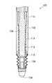
図3に、従来の接触式変位測定器の一例を示す。図3は、接触式変位測定器の主要部である接触式変位測定ヘッド100の断面図である。接触式変位測定ヘッド100は、円筒状の本体102の下端に上下動可能な接触子104を有し、接触子104と本体102との間はゴム製の蛇腹106で包囲されている。
FIG. 3 shows an example of a conventional contact displacement measuring instrument. FIG. 3 is a cross-sectional view of the contact-type
本体102の内部には接触子104と接続し接触子104と共に上下動するロッド(プローブ部材)108が配置されている。ロッド108はバネ110によって付勢されており、ロッド108が付勢されることにより接触子104は下方(突出する方向)に付勢されている。
A rod (probe member) 108 that is connected to the
また、ロッド108と本体102との間には、ロッド108の移動を滑らかにするためにベアリング(スチールボール)112が配置されており、ベアリング112はリテーナ114によって保持されている。また、ベアリング112とリテーナ114によって構成されるリニアボールブッシュの下方への移動を規制するために下降端ストッパ116が本体102の下端内側に設けられている。
A bearing (steel ball) 112 is disposed between the
しかしながら、上述したような従来の接触式変位測定器を垂直方向に設置して連続的に測定していると、リニアボールブッシュ自体の自重によってリニアボールブッシュが下方に下がり、下降端ストッパに接触して接触子が下がりきらなかったり、あるいは測定ポイントに近い位置でリニアボールブッシュの干渉があった場合には接触子の動きに影響して、測定値にバラツキが生じる虞があるという問題がある。 However, when the conventional contact displacement measuring instrument as described above is installed in the vertical direction and continuously measured, the linear ball bushing falls downward due to the weight of the linear ball bushing itself and contacts the descending end stopper. If the contact does not fall down or there is interference with the linear ball bush at a position close to the measurement point, there is a problem that the measured value may vary due to the movement of the contact.
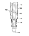
これに対して、図4に示すようにロッド108と本体102との間のスライドガイドを滑り軸受構造とし、精度の安定化を図ることが考えられる。またここで図3や図4に示すように、一般的なペンシル型の変位測定ヘッドの先端部には蛇腹106が設けられ、接触子104の摺動部への異物侵入を防止し、接触子104の摺動部を保護している。
On the other hand, as shown in FIG. 4, it is conceivable that the slide guide between the
しかし、このように蛇腹106を設けると、例えば図4に示すようにスライドガイドを滑りブッシュ方式とした場合には、接触子104が伸縮する際の蛇腹106内の空気はロッド108と本体102との間の僅かな摺動隙間120を通って移動するしかなく、接触子104の動きに影響し、測定値がバラつく要因となるという問題がある。
However, when the
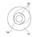
またこの時図5に本体102の軸方向に垂直な断面を示すように、ロッド108の外周部に空気の逃げ部122を設けて、摺動抵抗を少なくすることも考えられる。このように空気の逃げ部122を設けることにより、接触子104が伸縮する際の蛇腹106内の空気が移動する際の通り道は若干大きくなり摺動抵抗を少なくすることはできるが、ロッド108及び接触子104の法線方向のガタが生じて測定精度が悪化するという問題がある。
At this time, as shown in FIG. 5 which shows a cross section perpendicular to the axial direction of the
さらに、接触子104及びロッド(プローブ部材)108の伸縮速度が速いと、摺動隙間120からの空気の逃げが追いつかずに、防塵用の蛇腹ブーツの隙間から空気が洩れることにより、防塵及び防水性能が劣化するという問題がある。
Further, when the expansion and contraction speed of the
本発明はこのような問題に鑑みて成されたものであり、プローブ部材の摺動部に滑り軸受けを用いた接触式変位測定器において、プローブ部材伸縮時の蛇腹ブーツ内の空気の移動をスムーズにして測定値バラツキを防止するとともにプローブ部材の伸縮速度が速い場合にも蛇腹ブーツでの防塵防水性能を損なわずに高精度の測定を行うことのできる接触式変位測定器を提供することを目的とする。 The present invention has been made in view of such problems, and in a contact displacement measuring instrument using a sliding bearing for the sliding portion of the probe member, the air movement in the bellows boot during the expansion and contraction of the probe member is smoothly performed. An object of the present invention is to provide a contact-type displacement measuring instrument that can prevent measurement value variation and perform high-precision measurement without damaging the dustproof and waterproof performance of the bellows boot even when the expansion speed of the probe member is high. And
前記目的を達成するために、本発明の接触式変位測定器は、測定対象物に当接して変位可能な接触子と、前記接触子と接続し滑り軸受構造により変位するプローブ部材と、前記接触子及び前記プローブ部材の間に設けられた蛇腹部と、前記プローブ部材の変位に対応した出力を行う差動トランスを有する接触式変位測定ヘッドを備えた接触式変位測定器であって、前記プローブ部材の変位に伴って前記蛇腹部が伸縮する時の前記蛇腹部内の空気を逃がす通路を前記プローブ部材の内部に設けたことを特徴とする。 In order to achieve the above object, a contact displacement measuring instrument according to the present invention comprises a contactor that is displaceable by contact with an object to be measured, a probe member that is connected to the contactor and is displaced by a sliding bearing structure, and the contact A contact-type displacement measuring instrument comprising a bellows portion provided between a child and the probe member, and a contact-type displacement measuring head having a differential transformer that performs an output corresponding to the displacement of the probe member. The probe member is characterized in that a passage for escaping air in the bellows portion when the bellows portion expands and contracts with the displacement of the member is provided inside the probe member.
これにより、プローブ部材の摺動部に滑り軸受けを用いた接触式変位測定器において、プローブ部材伸縮時の蛇腹ブーツ内の空気の移動をスムーズにして測定値バラツキを防止するとともにプローブ部材の伸縮速度が速い場合にも蛇腹ブーツでの防塵防水性能を損なわずに高精度の測定を行うことが可能となる。 As a result, in a contact-type displacement measuring instrument that uses a sliding bearing for the sliding part of the probe member, the movement of the air in the bellows boot during the expansion and contraction of the probe member is made smooth to prevent measurement value variation and the expansion and contraction speed of the probe member Even when the speed is high, high-precision measurement can be performed without impairing the dustproof and waterproof performance of the bellows boots.
また、一つの実施態様として、前記通路は、前記プローブ部材下部の側壁に設けられた第1の開口部によって前記蛇腹部の内部と連通することが好ましい。 Moreover, as one embodiment, it is preferable that the passage communicates with the inside of the bellows part through a first opening provided in a side wall of the probe member lower part.
また、一つの実施態様として、前記接触式変位測定ヘッドは完全防水仕様であり、前記接触式変位測定ヘッド内に、前記プローブ部材の変位に伴って前記蛇腹部が伸縮する時の前記蛇腹部内の空気を貯留するように前記通路と連通し容積可変に形成された空気溜まりを備えたことが好ましい。 Also, as one embodiment, the contact displacement measuring head is completely waterproof, and the contact displacement measuring head has an inside of the bellows portion when the bellows portion expands and contracts with the displacement of the probe member. It is preferable to provide an air reservoir formed in a variable volume in communication with the passage so as to store air.
これにより、接触式変位測定器が完全防水仕様の場合においても、プローブ部材が変位する時の蛇腹ブーツ内の空気をプローブ部材内部に形成された通路と連通する空気溜まりで吸収することによってプローブ部材伸縮時の蛇腹ブーツ内の空気の移動をスムーズにして測定値バラツキを防止することが可能となる。 As a result, even when the contact-type displacement measuring instrument is completely waterproof, the probe member is absorbed by the air reservoir communicating with the passage formed inside the probe member when the probe member is displaced. It is possible to smoothly move the air in the bellows boot during expansion and contraction to prevent measurement value variation.
また、一つの実施態様として、前記空気溜まりと前記通路とを連通するために、前記接触式変位測定ヘッドの本体を形成する外筒内の上部の隙間と前記通路とを連通するように前記通路上部に設けられた第2の開口部と、前記外筒内の上部の隙間と前記空気溜まりとを連通する第3の開口部とを備えたことが好ましい。 Further, as one embodiment, in order to communicate the air reservoir and the passage, the passage is communicated with an upper gap in an outer cylinder forming a main body of the contact displacement measuring head and the passage. It is preferable that a second opening provided in the upper portion and a third opening communicating the upper gap in the outer cylinder and the air reservoir are provided.
また、一つの実施態様として、前記空気溜まりは、前記接触式変位測定ヘッドの本体を形成する外筒の上部に設けられた少なくとも外壁の一部が弾性部材で形成された空気貯留室であることが好ましい。 In one embodiment, the air reservoir is an air storage chamber in which at least a part of an outer wall provided at an upper part of an outer cylinder forming a main body of the contact displacement measuring head is formed of an elastic member. Is preferred.
また、一つの実施態様として、前記弾性部材はゴムであることが好ましい。 In one embodiment, the elastic member is preferably rubber.
このように、外壁の一部がゴム等の弾性部材で形成された空気貯留室で空気溜まりを形成することにより、接触式変位測定器が完全防水仕様の場合においても、プローブ部材が変位する時の蛇腹ブーツ内の空気を空気貯留室で吸収することによりプローブ部材伸縮時の蛇腹ブーツ内の空気の移動をスムーズにして測定値バラツキを防止することが可能となる。 In this way, by forming an air reservoir in an air storage chamber in which a part of the outer wall is formed of an elastic member such as rubber, the probe member is displaced even when the contact displacement measuring instrument is completely waterproof. By absorbing the air in the bellows boot in the air storage chamber, it is possible to smoothly move the air in the bellows boot when the probe member expands and contracts, and to prevent variation in the measured value.
以上説明したように、本発明によれば、プローブ部材の摺動部に滑り軸受けを用いた接触式変位測定器において、プローブ部材の変位に伴って蛇腹部が伸縮する時の蛇腹部内の空気を逃がす通路をプローブ部材の内部に設け、このプローブ部材内部の通路により空気を移動させたことにより、プローブ部材伸縮時の蛇腹ブーツ内の空気の移動をスムーズにして測定値バラツキを防止するとともにプローブ部材の伸縮速度が速い場合にも蛇腹ブーツでの防塵防水性能を損なわずに高精度の測定を行うことが可能となる。 As described above, according to the present invention, in the contact-type displacement measuring device using the sliding bearing for the sliding portion of the probe member, the air in the bellows portion when the bellows portion expands and contracts with the displacement of the probe member. By providing a passage for escaping inside the probe member and moving the air through the passage inside the probe member, the movement of the air in the bellows boot during the expansion and contraction of the probe member is smoothed, and measurement value variation is prevented and the probe member It is possible to perform highly accurate measurement without impairing the dustproof and waterproof performance of the bellows boots even when the expansion / contraction speed is high.
以下、添付図面を参照して、本発明に係る接触式変位測定器について詳細に説明する。 Hereinafter, a contact-type displacement measuring device according to the present invention will be described in detail with reference to the accompanying drawings.
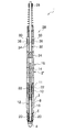
図1は、本発明の一実施形態に係る接触式変位測定器の接触式変位測定ヘッドの全体構成を示す断面図である。 FIG. 1 is a cross-sectional view showing the overall configuration of a contact displacement measuring head of a contact displacement measuring instrument according to an embodiment of the present invention.
図1に示すように、本実施形態の接触式変位測定ヘッド1は、円筒状の本体を形成する外筒2の下端に上下動可能な接触子4を備え、接触子4と外筒2との間にはゴム製の蛇腹(蛇腹ブーツ)6が設けられている。
As shown in FIG. 1, the contact displacement measuring head 1 of this embodiment includes a contact 4 that can move up and down at the lower end of an
外筒2の内部には接触子4と接続し接触子4と共に上下動するプローブ部材(ロッド)8が配置されている。プローブ部材8の上部にはコア軸10が取り付けられ、コア軸10はバネ(圧縮バネ)11によって付勢されている。これにより、プローブ部材8が付勢され、さらに接触子4が下方(突出する方向)に付勢されている。
A probe member (rod) 8 that is connected to the contact 4 and moves up and down together with the contact 4 is disposed inside the
また、プローブ部材8と外筒2との間は、数ミクロンのクリアランス12でガイドされ、滑り軸受けを構成している。
The
プローブ部材8に取り付けられたコア軸10の他端には差動トランスを構成するコア14が取り付けられており、コア14に対応してその周囲の外筒2’には同じく差動トランスを構成するコイルユニット16が組み込まれている。
A
蛇腹(蛇腹ブーツ)6は、滑り軸受部への埃等の異物や水の侵入を防止しプローブ部材8摺動部を保護するため防塵性、防水性を有し、気密性を有している。また、本実施形態の接触式変位測定ヘッド1は、完全防水仕様であり、上部も完全にシール構造となっている。
The bellows (bellows boots) 6 is dustproof, waterproof, and airtight in order to prevent foreign matters such as dust and water from entering the sliding bearing portion and protect the sliding portion of the
従って、接触子4及びプローブ部材8が伸縮する際、蛇腹6内の空気が蛇腹6内からスムーズに出入りできるように空気の逃げ場所を確保しておく必要がある。
Therefore, when the contact 4 and the
そこで、プローブ部材8の内部を空洞にして空気を通すための通路18が形成されるとともに、プローブ部材8の伸縮時に蛇腹6内の空気をこの通路18内に逃がすための開口部(第1の開口部)20が、プローブ部材8下部に設けられている。
Therefore, a
このプローブ部材8内に設けられた空気の通路18は、コア軸10に設けられた開口部(第2の開口部)22と繋がっている。そして、通路18を通った空気はこのコア軸10に設けられた開口部22からコア軸10と本体の外筒2の隙間を通りさらに上のコア14及びコイルユニット16の隙間を通って上へと流れて行く。
The
また、コア14及びコイルユニット16で構成される差動トランスの検出信号は、コイルユニット16の上部に配設されたケーブル26を通じて図示を省略した外部のコントローラに送られる。
The detection signal of the differential transformer composed of the
この差動トランスの上部に配置されたケーブル接続部28は、本実施形態の接触式変位測定器のように完全防水仕様の場合には、シール構造となっており、蛇腹6が収縮して蛇腹6内の空気が開口部20、及び22を介して上部に流れてきた場合に、このままでは行き場所がなくなってしまう。
The
そこで、本実施形態では、ケーブル接続部28に蛇腹6より流入してくる空気を貯留するバッファエリアとしての空気貯留室(空気溜まり)30を備えている。
Therefore, in the present embodiment, an air storage chamber (air reservoir) 30 is provided as a buffer area for storing the air flowing into the
空気貯留室30は、接触式変位測定ヘッド1の本体を形成する外筒2’内に設けられ、ケーブル接続部28の内部に開口部(第3の開口部)34が形成されて、ケーブル26との隙間32を通りこの開口部34から空気貯留室30に空気が出入りするようになっている。
The
また、空気貯留室30の外壁はゴム等の弾性部材で形成された伸縮自在な弾性壁36となっている。空気貯留室30内に空気を貯留する場合には、この弾性壁36が空気の圧力で伸び、空気貯留室30の容積が増大することによって、空気を空気貯留室30内に吸収するようになっている。
The outer wall of the
空気貯留室30は、ケーブル接続部28の周囲に複数(例えば2つ)形成されるが、設置する個数は特に限定されず、例えば全周にわたって一続きの部屋として形成してもよい。また、空気貯留室30を設置する場所も特にケーブル接続部28に限定されず、他の場所に設置してもよい。
A plurality (for example, two) of the
なお、図1は、プローブ部材8が伸張している状態を示しており、この状態においては、蛇腹6も伸びており蛇腹6内に空気が溜まっていて、空気貯留室30の弾性壁36も平らな状態となっている。
FIG. 1 shows a state in which the
図2に、プローブ部材8が収縮した状態を示す。
FIG. 2 shows a state where the
図2に示すように、接触子4を被測定物(図示省略)に押圧することにより接触子4が上方に押され、プローブ部材8も上方に移動し、蛇腹6が収縮する。これにより、蛇腹6内の空気が開口部20を通って、プローブ部材8の内部に形成された通路18を介して上方に流れて行く。
As shown in FIG. 2, when the contact 4 is pressed against an object to be measured (not shown), the contact 4 is pushed upward, the
プローブ部材8内の通路18を流れた空気はその上部に設けられた開口部22から外筒2内に流入し、差動トランス部のコア14、コイルユニット16の隙間をさらに上に流れ、開口部34から空気貯留室30に流入する。
The air that has flowed through the
空気貯留室30内に空気が流入すると、その圧力によって弾性壁36が押されて外側に伸びて膨らみ、空気貯留室30の容積が増大し、空気を吸収する。
When air flows into the
これにより、蛇腹6が収縮して流出した空気は、プローブ部材8の内部に形成された通路18を移動して空気貯留室30に貯留される。従って、蛇腹6から流出した空気はスムーズに移動することができ、プローブ部材8の摺動部の動きに影響を与えて測定精度を悪化させるようなことはない。
Thereby, the air that has flowed out due to the contraction of the
変位測定器は、主に機械加工中あるいは機械加工後の部品の寸法検査に用いられることが多く、高精度で高速に測定することが要求される。ここで非接触式の変位測定器は作業環境に敏感であることから、比較的劣悪な作業環境においては接触式変位測定器が用いられる。このように測定環境の悪い中で用いられる接触式変位測定器は、防塵、防水が必須となっている。 Displacement measuring instruments are often used mainly for dimensional inspection of parts during or after machining, and are required to measure with high accuracy and high speed. Here, since the non-contact displacement measuring instrument is sensitive to the work environment, the contact displacement measuring instrument is used in a relatively poor working environment. As described above, the contact displacement measuring instrument used in a poor measurement environment is required to be dustproof and waterproof.
本実施形態によれば、このような完全防水仕様の接触式変位測定器において、蛇腹の収縮に伴う空気の逃げ場所を確保することにより、滑り軸受(滑りブッシュ)方式で防水対応が可能で、高精度な測定を行うことが可能となる。 According to this embodiment, in such a completely waterproof contact displacement measuring instrument, by securing a place of air escape due to the contraction of the bellows, it is possible to support waterproofing with a sliding bearing (sliding bush) system, It becomes possible to perform highly accurate measurement.
すなわち、プローブ部材伸縮時の蛇腹ブーツ内の空気がプローブ部材内に形成された通路及び外筒内に形成された複数の開口部を通って空気貯留室に抵抗なく行き来できるため、プローブ部材の動きもスムーズとなり、測定精度のバラツキを抑制するとともに、蛇腹ブーツ部における防塵、防水性能の劣化を防止することができる。 That is, since the air in the bellows boot when the probe member is expanded and contracted can pass through the passage formed in the probe member and the plurality of openings formed in the outer cylinder without resistance, the movement of the probe member As a result, the variation in measurement accuracy can be suppressed, and the dustproof and waterproof performance of the bellows boot can be prevented from being deteriorated.
なお、今まで説明してきた例は、完全防水仕様の接触式変位測定器であったが、このような完全防水仕様でない場合には、接触式変位測定ヘッドの上部が開いているため、特に空気貯留室30を設けることなく、蛇腹6から流出した空気を、開口部20、プローブ部材8内の通路18及び開口部22等を介して上方に流して、そのまま上部の開口から接触式変位測定ヘッド外に逃がしてやればよい。
The example described so far is a contact type displacement measuring instrument with a completely waterproof specification. However, if the contact type displacement measuring head is not fully waterproof, the top of the contact type displacement measuring head is open. Without providing the
このように、プローブ部材伸縮時に蛇腹内の空気を開口部を介してプローブ部材の内部に設けられた空気の通路に流し、この通路から接触式変位測定ヘッド上部の開口を通じて外部に空気を逃がすようにすることによって、完全防水仕様でない場合においても、プローブ部材摺動部の動きをスムーズにし、測定精度の悪化を防ぐことができる。 As described above, when the probe member is expanded and contracted, the air in the bellows is caused to flow through the opening to the air passage provided inside the probe member, and the air is allowed to escape to the outside through the opening at the upper part of the contact displacement measuring head. By doing so, even when it is not completely waterproof, the movement of the probe member sliding portion can be made smooth, and the deterioration of the measurement accuracy can be prevented.
以上、本発明の接触式変位測定器について詳細に説明したが、本発明は、以上の例には限定されず、本発明の要旨を逸脱しない範囲において、各種の改良や変形を行ってもよいのはもちろんである。 The contact displacement measuring instrument of the present invention has been described in detail above, but the present invention is not limited to the above examples, and various improvements and modifications may be made without departing from the spirit of the present invention. Of course.
1…接触式変位測定ヘッド、2、2’…外筒(本体)、4…接触子、6…蛇腹(蛇腹ブーツ)、8…プローブ部材、10…コア軸、11…バネ、12…クリアランス、14…コア、16…コイルユニット、18…(プローブ部材内に形成された空気の)通路、20、22…開口部、26…ケーブル、28…ケーブル接続部、30…空気貯留室、32…隙間、34…開口部、36…弾性壁
DESCRIPTION OF SYMBOLS 1 ... Contact-type
Claims (6)
前記外筒の一端に備えられ、測定対象物に当接して変位可能な接触子と、
前記外筒の内部に配置され、滑り軸受構造によって前記外筒に摺動自在に支持されると共に、前記接触子に接続されて、前記接触子と共に変位するプローブ部材と、
前記接触子及び前記外筒の間に設けられた蛇腹部と、
前記外筒の内部に配置され、前記プローブ部材の変位に対応した出力を行う差動トランスと、
前記外筒の他端に備えられ、前記差動トランスの検出信号を出力するケーブルが接続されるケーブル接続部であって、シール構造を有するケーブル接続部と、
を有する接触式変位測定ヘッドを備えた接触式変位測定器であって、
前記プローブ部材の内部に設けられる通路と、
前記蛇腹部の内側に形成される空間と前記通路とを連通する第1の開口部と、
前記外筒の内部に形成される空間と前記通路とを連通する第2の開口部と、
前記外筒の周囲に設けられ、外壁が弾性部材で形成された空気貯留室と、
前記空気貯留室と前記外筒の内部に形成される空間とを連通する第3の開口部と、
を備えたことを特徴とする接触式変位測定器。 An outer cylinder forming a main body;
A contact that is provided at one end of the outer cylinder and is displaceable in contact with a measurement object;
A probe member disposed inside the outer cylinder, slidably supported by the outer cylinder by a sliding bearing structure, connected to the contact, and displaced together with the contact ;
A bellows part provided between the contact and the outer cylinder ;
A differential transformer that is disposed inside the outer cylinder and that performs output corresponding to the displacement of the probe member ;
A cable connecting portion provided at the other end of the outer cylinder and connected to a cable that outputs a detection signal of the differential transformer, the cable connecting portion having a seal structure
A contact-type displacement measuring device comprising a contact-type displacement measuring head having
A passage provided inside the probe member;
A first opening communicating the space formed inside the bellows portion and the passage;
A second opening communicating the space formed inside the outer cylinder and the passage;
An air storage chamber provided around the outer cylinder and having an outer wall formed of an elastic member;
A third opening communicating the air storage chamber and a space formed inside the outer cylinder;
Contact displacement meter, characterized in that it comprises a.
Priority Applications (1)
| Application Number | Priority Date | Filing Date | Title |
|---|---|---|---|
| JP2011047853A JP5698564B2 (en) | 2011-03-04 | 2011-03-04 | Contact displacement measuring instrument |
Applications Claiming Priority (1)
| Application Number | Priority Date | Filing Date | Title |
|---|---|---|---|
| JP2011047853A JP5698564B2 (en) | 2011-03-04 | 2011-03-04 | Contact displacement measuring instrument |
Publications (2)
| Publication Number | Publication Date |
|---|---|
| JP2012185019A JP2012185019A (en) | 2012-09-27 |
| JP5698564B2 true JP5698564B2 (en) | 2015-04-08 |
Family
ID=47015235
Family Applications (1)
| Application Number | Title | Priority Date | Filing Date |
|---|---|---|---|
| JP2011047853A Expired - Fee Related JP5698564B2 (en) | 2011-03-04 | 2011-03-04 | Contact displacement measuring instrument |
Country Status (1)
| Country | Link |
|---|---|
| JP (1) | JP5698564B2 (en) |
Families Citing this family (5)
| Publication number | Priority date | Publication date | Assignee | Title |
|---|---|---|---|---|
| JP2016099221A (en) * | 2014-11-21 | 2016-05-30 | 株式会社小野測器 | Probe device, laser measurement device, and laser measurement system |
| JP6552872B2 (en) * | 2015-05-08 | 2019-07-31 | 株式会社ミツトヨ | Measuring instrument |
| CN113945138B (en) * | 2021-11-01 | 2025-05-02 | 安徽省广德中鼎汽车工具有限公司 | External surface curvature detection device for wheel maintenance and use method thereof |
| CN117324610A (en) * | 2023-09-21 | 2024-01-02 | 沈阳铝镁设计研究院有限公司 | Thermal state metal transfer ladle and operation method |
| CN118758142B (en) * | 2024-09-09 | 2024-11-05 | 珠海芯烨电子科技有限公司 | A fine-adjustable sleeve type micrometer head |
Family Cites Families (2)
| Publication number | Priority date | Publication date | Assignee | Title |
|---|---|---|---|---|
| JPS54112029U (en) * | 1977-06-15 | 1979-08-07 | ||
| JPS59168111U (en) * | 1983-04-27 | 1984-11-10 | ソニ−マグネスケ−ル株式会社 | Measuring device |
-
2011
- 2011-03-04 JP JP2011047853A patent/JP5698564B2/en not_active Expired - Fee Related
Also Published As
| Publication number | Publication date |
|---|---|
| JP2012185019A (en) | 2012-09-27 |
Similar Documents
| Publication | Publication Date | Title |
|---|---|---|
| JP5698564B2 (en) | Contact displacement measuring instrument | |
| CN109154535A (en) | Apparatus for testing weeping | |
| US9885615B2 (en) | Movable contact sensor assembly having sealed construction | |
| US10519938B2 (en) | Spring device | |
| CN105953968B (en) | A kind of novel ultrahigh pressure pressure sensor and pressure detection method | |
| JP5265210B2 (en) | Static pressure gas bearing and gas pressure actuator for piston drive mechanism | |
| JP5986882B2 (en) | Float type level gauge | |
| KR101947074B1 (en) | Cushion structure of hydraulic cylinder provided with internally installed linear position sensor of piston | |
| JP2009162590A (en) | Pressure monitoring device | |
| JP5651499B2 (en) | Posture maintenance tool for front forks | |
| JP2006162491A (en) | Pressure sensor | |
| KR102365105B1 (en) | Push-pull gage for an elevator, escalator and moving walk | |
| CN109580141A (en) | A kind of damping spring test device | |
| JP6242159B2 (en) | Length measuring instrument | |
| JP6552872B2 (en) | Measuring instrument | |
| JP6474680B2 (en) | Linear gauge | |
| US20260070386A1 (en) | Shock assembly and method for determining a position of an internal floating piston of a shock assembly | |
| JP6616702B2 (en) | Linear gauge and finite linear motion guide device | |
| JP2023506142A (en) | Working cylinder with cushioned end stroke | |
| KR102833159B1 (en) | Storage container support device with sliding unit | |
| RU2543677C1 (en) | Meter of tubular channel bending | |
| TW202026548A (en) | Linear transimission device | |
| JP6951183B2 (en) | Measuring instrument | |
| JP2009162251A (en) | Cylinder device | |
| JP2018173300A (en) | Measuring instrument and measuring system |
Legal Events
| Date | Code | Title | Description |
|---|---|---|---|
| A621 | Written request for application examination |
Free format text: JAPANESE INTERMEDIATE CODE: A621 Effective date: 20140107 |
|
| A977 | Report on retrieval |
Free format text: JAPANESE INTERMEDIATE CODE: A971007 Effective date: 20140704 |
|
| A131 | Notification of reasons for refusal |
Free format text: JAPANESE INTERMEDIATE CODE: A131 Effective date: 20140709 |
|
| A521 | Request for written amendment filed |
Free format text: JAPANESE INTERMEDIATE CODE: A523 Effective date: 20140904 |
|
| TRDD | Decision of grant or rejection written | ||
| A01 | Written decision to grant a patent or to grant a registration (utility model) |
Free format text: JAPANESE INTERMEDIATE CODE: A01 Effective date: 20150204 |
|
| A61 | First payment of annual fees (during grant procedure) |
Free format text: JAPANESE INTERMEDIATE CODE: A61 Effective date: 20150213 |
|
| R150 | Certificate of patent or registration of utility model |
Ref document number: 5698564 Country of ref document: JP Free format text: JAPANESE INTERMEDIATE CODE: R150 |
|
| R250 | Receipt of annual fees |
Free format text: JAPANESE INTERMEDIATE CODE: R250 |
|
| R250 | Receipt of annual fees |
Free format text: JAPANESE INTERMEDIATE CODE: R250 |
|
| R250 | Receipt of annual fees |
Free format text: JAPANESE INTERMEDIATE CODE: R250 |
|
| R250 | Receipt of annual fees |
Free format text: JAPANESE INTERMEDIATE CODE: R250 |
|
| R250 | Receipt of annual fees |
Free format text: JAPANESE INTERMEDIATE CODE: R250 |
|
| R250 | Receipt of annual fees |
Free format text: JAPANESE INTERMEDIATE CODE: R250 |
|
| LAPS | Cancellation because of no payment of annual fees |